WO2022259724A1 - Power storage element - Google Patents
Power storage element Download PDFInfo
- Publication number
- WO2022259724A1 WO2022259724A1 PCT/JP2022/015251 JP2022015251W WO2022259724A1 WO 2022259724 A1 WO2022259724 A1 WO 2022259724A1 JP 2022015251 W JP2022015251 W JP 2022015251W WO 2022259724 A1 WO2022259724 A1 WO 2022259724A1
- Authority
- WO
- WIPO (PCT)
- Prior art keywords
- negative electrode
- active material
- electrode active
- graphite
- storage element
- Prior art date
Links
- 238000003860 storage Methods 0.000 title claims abstract description 112
- OKTJSMMVPCPJKN-UHFFFAOYSA-N Carbon Chemical compound [C] OKTJSMMVPCPJKN-UHFFFAOYSA-N 0.000 claims abstract description 117
- 239000007773 negative electrode material Substances 0.000 claims abstract description 116
- 229910002804 graphite Inorganic materials 0.000 claims abstract description 97
- 239000010439 graphite Substances 0.000 claims abstract description 97
- 239000007787 solid Substances 0.000 claims abstract description 43
- 239000002245 particle Substances 0.000 claims description 88
- 238000009826 distribution Methods 0.000 claims description 18
- 229910021383 artificial graphite Inorganic materials 0.000 claims description 12
- 238000000034 method Methods 0.000 description 45
- 239000011255 nonaqueous electrolyte Substances 0.000 description 35
- 239000007774 positive electrode material Substances 0.000 description 34
- 239000000463 material Substances 0.000 description 33
- 239000011230 binding agent Substances 0.000 description 22
- 238000007600 charging Methods 0.000 description 19
- -1 lithium transition metal Chemical class 0.000 description 18
- 239000000758 substrate Substances 0.000 description 18
- 239000006258 conductive agent Substances 0.000 description 17
- 239000000523 sample Substances 0.000 description 17
- 230000000052 comparative effect Effects 0.000 description 16
- IJGRMHOSHXDMSA-UHFFFAOYSA-N Atomic nitrogen Chemical compound N#N IJGRMHOSHXDMSA-UHFFFAOYSA-N 0.000 description 14
- 239000003792 electrolyte Substances 0.000 description 14
- 230000002829 reductive effect Effects 0.000 description 12
- 239000000203 mixture Substances 0.000 description 11
- 239000002562 thickening agent Substances 0.000 description 11
- 238000007599 discharging Methods 0.000 description 10
- PXHVJJICTQNCMI-UHFFFAOYSA-N nickel Substances [Ni] PXHVJJICTQNCMI-UHFFFAOYSA-N 0.000 description 10
- 229920005989 resin Polymers 0.000 description 10
- 239000011347 resin Substances 0.000 description 10
- 229910052782 aluminium Inorganic materials 0.000 description 9
- 239000003575 carbonaceous material Substances 0.000 description 9
- 239000011888 foil Substances 0.000 description 9
- 229910052751 metal Inorganic materials 0.000 description 9
- 230000008569 process Effects 0.000 description 9
- 230000000452 restraining effect Effects 0.000 description 9
- 150000003839 salts Chemical class 0.000 description 9
- RYGMFSIKBFXOCR-UHFFFAOYSA-N Copper Chemical compound [Cu] RYGMFSIKBFXOCR-UHFFFAOYSA-N 0.000 description 8
- HBBGRARXTFLTSG-UHFFFAOYSA-N Lithium ion Chemical compound [Li+] HBBGRARXTFLTSG-UHFFFAOYSA-N 0.000 description 8
- 239000003125 aqueous solvent Substances 0.000 description 8
- 150000005678 chain carbonates Chemical class 0.000 description 8
- 238000005336 cracking Methods 0.000 description 8
- 150000005676 cyclic carbonates Chemical class 0.000 description 8
- 230000000694 effects Effects 0.000 description 8
- 229910001416 lithium ion Inorganic materials 0.000 description 8
- 238000004519 manufacturing process Methods 0.000 description 8
- 238000005259 measurement Methods 0.000 description 8
- 239000002184 metal Substances 0.000 description 8
- 229910052757 nitrogen Inorganic materials 0.000 description 8
- 229920000642 polymer Polymers 0.000 description 8
- 238000003825 pressing Methods 0.000 description 8
- 238000001878 scanning electron micrograph Methods 0.000 description 8
- 238000012360 testing method Methods 0.000 description 8
- KMTRUDSVKNLOMY-UHFFFAOYSA-N Ethylene carbonate Chemical compound O=C1OCCO1 KMTRUDSVKNLOMY-UHFFFAOYSA-N 0.000 description 7
- 239000002033 PVDF binder Substances 0.000 description 7
- XAGFODPZIPBFFR-UHFFFAOYSA-N aluminium Chemical compound [Al] XAGFODPZIPBFFR-UHFFFAOYSA-N 0.000 description 7
- 239000013078 crystal Substances 0.000 description 7
- JBTWLSYIZRCDFO-UHFFFAOYSA-N ethyl methyl carbonate Chemical compound CCOC(=O)OC JBTWLSYIZRCDFO-UHFFFAOYSA-N 0.000 description 7
- 239000000945 filler Substances 0.000 description 7
- 229910052744 lithium Inorganic materials 0.000 description 7
- 229920002981 polyvinylidene fluoride Polymers 0.000 description 7
- 239000007784 solid electrolyte Substances 0.000 description 7
- 239000006230 acetylene black Substances 0.000 description 6
- 239000003990 capacitor Substances 0.000 description 6
- 239000011889 copper foil Substances 0.000 description 6
- IEJIGPNLZYLLBP-UHFFFAOYSA-N dimethyl carbonate Chemical compound COC(=O)OC IEJIGPNLZYLLBP-UHFFFAOYSA-N 0.000 description 6
- 229910003002 lithium salt Inorganic materials 0.000 description 6
- 159000000002 lithium salts Chemical class 0.000 description 6
- 229910021382 natural graphite Inorganic materials 0.000 description 6
- 238000001179 sorption measurement Methods 0.000 description 6
- 239000010936 titanium Substances 0.000 description 6
- 229910052723 transition metal Inorganic materials 0.000 description 6
- 239000004698 Polyethylene Substances 0.000 description 5
- VYPSYNLAJGMNEJ-UHFFFAOYSA-N Silicium dioxide Chemical compound O=[Si]=O VYPSYNLAJGMNEJ-UHFFFAOYSA-N 0.000 description 5
- 239000000654 additive Substances 0.000 description 5
- 229910052799 carbon Inorganic materials 0.000 description 5
- 150000001875 compounds Chemical class 0.000 description 5
- HNPSIPDUKPIQMN-UHFFFAOYSA-N dioxosilane;oxo(oxoalumanyloxy)alumane Chemical compound O=[Si]=O.O=[Al]O[Al]=O HNPSIPDUKPIQMN-UHFFFAOYSA-N 0.000 description 5
- 229920000573 polyethylene Polymers 0.000 description 5
- 239000000843 powder Substances 0.000 description 5
- 238000002360 preparation method Methods 0.000 description 5
- 239000002904 solvent Substances 0.000 description 5
- 239000000126 substance Substances 0.000 description 5
- 229910052719 titanium Inorganic materials 0.000 description 5
- XLYOFNOQVPJJNP-UHFFFAOYSA-N water Substances O XLYOFNOQVPJJNP-UHFFFAOYSA-N 0.000 description 5
- VTYYLEPIZMXCLO-UHFFFAOYSA-L Calcium carbonate Chemical compound [Ca+2].[O-]C([O-])=O VTYYLEPIZMXCLO-UHFFFAOYSA-L 0.000 description 4
- WHXSMMKQMYFTQS-UHFFFAOYSA-N Lithium Chemical compound [Li] WHXSMMKQMYFTQS-UHFFFAOYSA-N 0.000 description 4
- SECXISVLQFMRJM-UHFFFAOYSA-N N-Methylpyrrolidone Chemical compound CN1CCCC1=O SECXISVLQFMRJM-UHFFFAOYSA-N 0.000 description 4
- RTAQQCXQSZGOHL-UHFFFAOYSA-N Titanium Chemical compound [Ti] RTAQQCXQSZGOHL-UHFFFAOYSA-N 0.000 description 4
- 239000012298 atmosphere Substances 0.000 description 4
- QVQLCTNNEUAWMS-UHFFFAOYSA-N barium oxide Chemical compound [Ba]=O QVQLCTNNEUAWMS-UHFFFAOYSA-N 0.000 description 4
- TZCXTZWJZNENPQ-UHFFFAOYSA-L barium sulfate Chemical compound [Ba+2].[O-]S([O-])(=O)=O TZCXTZWJZNENPQ-UHFFFAOYSA-L 0.000 description 4
- 239000006229 carbon black Substances 0.000 description 4
- 239000002131 composite material Substances 0.000 description 4
- 238000010277 constant-current charging Methods 0.000 description 4
- 229910052802 copper Inorganic materials 0.000 description 4
- 239000010949 copper Substances 0.000 description 4
- 239000002612 dispersion medium Substances 0.000 description 4
- 150000002484 inorganic compounds Chemical class 0.000 description 4
- 229910010272 inorganic material Inorganic materials 0.000 description 4
- 239000007788 liquid Substances 0.000 description 4
- 239000002905 metal composite material Substances 0.000 description 4
- 150000002739 metals Chemical class 0.000 description 4
- 238000010298 pulverizing process Methods 0.000 description 4
- 229910052710 silicon Inorganic materials 0.000 description 4
- IATRAKWUXMZMIY-UHFFFAOYSA-N strontium oxide Chemical compound [O-2].[Sr+2] IATRAKWUXMZMIY-UHFFFAOYSA-N 0.000 description 4
- 229910052718 tin Inorganic materials 0.000 description 4
- VAYTZRYEBVHVLE-UHFFFAOYSA-N 1,3-dioxol-2-one Chemical compound O=C1OC=CO1 VAYTZRYEBVHVLE-UHFFFAOYSA-N 0.000 description 3
- 229910000838 Al alloy Inorganic materials 0.000 description 3
- 229920002134 Carboxymethyl cellulose Polymers 0.000 description 3
- 229920002943 EPDM rubber Polymers 0.000 description 3
- 229910001290 LiPF6 Inorganic materials 0.000 description 3
- 239000004743 Polypropylene Substances 0.000 description 3
- GWEVSGVZZGPLCZ-UHFFFAOYSA-N Titan oxide Chemical compound O=[Ti]=O GWEVSGVZZGPLCZ-UHFFFAOYSA-N 0.000 description 3
- 239000011149 active material Substances 0.000 description 3
- 229910000323 aluminium silicate Inorganic materials 0.000 description 3
- 239000011575 calcium Substances 0.000 description 3
- 229910052791 calcium Inorganic materials 0.000 description 3
- 229910021393 carbon nanotube Inorganic materials 0.000 description 3
- 239000002041 carbon nanotube Substances 0.000 description 3
- 238000004891 communication Methods 0.000 description 3
- 238000002591 computed tomography Methods 0.000 description 3
- 230000008602 contraction Effects 0.000 description 3
- 238000001816 cooling Methods 0.000 description 3
- 230000007423 decrease Effects 0.000 description 3
- 229910052731 fluorine Inorganic materials 0.000 description 3
- 229910021389 graphene Inorganic materials 0.000 description 3
- 230000002401 inhibitory effect Effects 0.000 description 3
- 238000010030 laminating Methods 0.000 description 3
- VLKZOEOYAKHREP-UHFFFAOYSA-N n-Hexane Chemical compound CCCCCC VLKZOEOYAKHREP-UHFFFAOYSA-N 0.000 description 3
- 229910052759 nickel Inorganic materials 0.000 description 3
- 239000004745 nonwoven fabric Substances 0.000 description 3
- 229920000447 polyanionic polymer Polymers 0.000 description 3
- 229920001155 polypropylene Polymers 0.000 description 3
- 238000012545 processing Methods 0.000 description 3
- 239000011734 sodium Substances 0.000 description 3
- 229910052708 sodium Inorganic materials 0.000 description 3
- 239000011029 spinel Substances 0.000 description 3
- 229910052596 spinel Inorganic materials 0.000 description 3
- 229920003048 styrene butadiene rubber Polymers 0.000 description 3
- ZZXUZKXVROWEIF-UHFFFAOYSA-N 1,2-butylene carbonate Chemical compound CCC1COC(=O)O1 ZZXUZKXVROWEIF-UHFFFAOYSA-N 0.000 description 2
- ZPFAVCIQZKRBGF-UHFFFAOYSA-N 1,3,2-dioxathiolane 2,2-dioxide Chemical compound O=S1(=O)OCCO1 ZPFAVCIQZKRBGF-UHFFFAOYSA-N 0.000 description 2
- YJTKZCDBKVTVBY-UHFFFAOYSA-N 1,3-Diphenylbenzene Chemical group C1=CC=CC=C1C1=CC=CC(C=2C=CC=CC=2)=C1 YJTKZCDBKVTVBY-UHFFFAOYSA-N 0.000 description 2
- BJWMSGRKJIOCNR-UHFFFAOYSA-N 4-ethenyl-1,3-dioxolan-2-one Chemical compound C=CC1COC(=O)O1 BJWMSGRKJIOCNR-UHFFFAOYSA-N 0.000 description 2
- SBLRHMKNNHXPHG-UHFFFAOYSA-N 4-fluoro-1,3-dioxolan-2-one Chemical compound FC1COC(=O)O1 SBLRHMKNNHXPHG-UHFFFAOYSA-N 0.000 description 2
- 239000005995 Aluminium silicate Substances 0.000 description 2
- BTBUEUYNUDRHOZ-UHFFFAOYSA-N Borate Chemical compound [O-]B([O-])[O-] BTBUEUYNUDRHOZ-UHFFFAOYSA-N 0.000 description 2
- 229910000881 Cu alloy Inorganic materials 0.000 description 2
- OIFBSDVPJOWBCH-UHFFFAOYSA-N Diethyl carbonate Chemical compound CCOC(=O)OCC OIFBSDVPJOWBCH-UHFFFAOYSA-N 0.000 description 2
- IAZDPXIOMUYVGZ-UHFFFAOYSA-N Dimethylsulphoxide Chemical compound CS(C)=O IAZDPXIOMUYVGZ-UHFFFAOYSA-N 0.000 description 2
- GUUVPOWQJOLRAS-UHFFFAOYSA-N Diphenyl disulfide Chemical compound C=1C=CC=CC=1SSC1=CC=CC=C1 GUUVPOWQJOLRAS-UHFFFAOYSA-N 0.000 description 2
- UQSXHKLRYXJYBZ-UHFFFAOYSA-N Iron oxide Chemical compound [Fe]=O UQSXHKLRYXJYBZ-UHFFFAOYSA-N 0.000 description 2
- 229910011328 LiNi0.6Co0.2Mn0.2O2 Inorganic materials 0.000 description 2
- 229910021314 NaFeO 2 Inorganic materials 0.000 description 2
- 239000004642 Polyimide Substances 0.000 description 2
- 229920000388 Polyphosphate Polymers 0.000 description 2
- 241000156302 Porcine hemagglutinating encephalomyelitis virus Species 0.000 description 2
- 229910052581 Si3N4 Inorganic materials 0.000 description 2
- 238000002441 X-ray diffraction Methods 0.000 description 2
- 229910021536 Zeolite Inorganic materials 0.000 description 2
- 230000000996 additive effect Effects 0.000 description 2
- 229910045601 alloy Inorganic materials 0.000 description 2
- 239000000956 alloy Substances 0.000 description 2
- 235000012211 aluminium silicate Nutrition 0.000 description 2
- 229910052586 apatite Inorganic materials 0.000 description 2
- 150000001491 aromatic compounds Chemical class 0.000 description 2
- 125000004429 atom Chemical group 0.000 description 2
- 229910052788 barium Inorganic materials 0.000 description 2
- OYLGJCQECKOTOL-UHFFFAOYSA-L barium fluoride Chemical compound [F-].[F-].[Ba+2] OYLGJCQECKOTOL-UHFFFAOYSA-L 0.000 description 2
- 229910001632 barium fluoride Inorganic materials 0.000 description 2
- 239000000440 bentonite Substances 0.000 description 2
- 229910000278 bentonite Inorganic materials 0.000 description 2
- SVPXDRXYRYOSEX-UHFFFAOYSA-N bentoquatam Chemical compound O.O=[Si]=O.O=[Al]O[Al]=O SVPXDRXYRYOSEX-UHFFFAOYSA-N 0.000 description 2
- 230000005540 biological transmission Effects 0.000 description 2
- 229910052796 boron Inorganic materials 0.000 description 2
- 229910052794 bromium Inorganic materials 0.000 description 2
- 229910000019 calcium carbonate Inorganic materials 0.000 description 2
- WUKWITHWXAAZEY-UHFFFAOYSA-L calcium difluoride Chemical compound [F-].[F-].[Ca+2] WUKWITHWXAAZEY-UHFFFAOYSA-L 0.000 description 2
- 229910001634 calcium fluoride Inorganic materials 0.000 description 2
- BRPQOXSCLDDYGP-UHFFFAOYSA-N calcium oxide Chemical compound [O-2].[Ca+2] BRPQOXSCLDDYGP-UHFFFAOYSA-N 0.000 description 2
- 239000000292 calcium oxide Substances 0.000 description 2
- ODINCKMPIJJUCX-UHFFFAOYSA-N calcium oxide Inorganic materials [Ca]=O ODINCKMPIJJUCX-UHFFFAOYSA-N 0.000 description 2
- 150000004649 carbonic acid derivatives Chemical class 0.000 description 2
- 150000001786 chalcogen compounds Chemical class 0.000 description 2
- 238000006243 chemical reaction Methods 0.000 description 2
- 229910052801 chlorine Inorganic materials 0.000 description 2
- 229910052804 chromium Inorganic materials 0.000 description 2
- 239000000805 composite resin Substances 0.000 description 2
- PMHQVHHXPFUNSP-UHFFFAOYSA-M copper(1+);methylsulfanylmethane;bromide Chemical compound Br[Cu].CSC PMHQVHHXPFUNSP-UHFFFAOYSA-M 0.000 description 2
- 238000005520 cutting process Methods 0.000 description 2
- 230000006866 deterioration Effects 0.000 description 2
- TXCDCPKCNAJMEE-UHFFFAOYSA-N dibenzofuran Chemical compound C1=CC=C2C3=CC=CC=C3OC2=C1 TXCDCPKCNAJMEE-UHFFFAOYSA-N 0.000 description 2
- 229910001873 dinitrogen Inorganic materials 0.000 description 2
- QXYJCZRRLLQGCR-UHFFFAOYSA-N dioxomolybdenum Chemical compound O=[Mo]=O QXYJCZRRLLQGCR-UHFFFAOYSA-N 0.000 description 2
- KZHJGOXRZJKJNY-UHFFFAOYSA-N dioxosilane;oxo(oxoalumanyloxy)alumane Chemical compound O=[Si]=O.O=[Si]=O.O=[Al]O[Al]=O.O=[Al]O[Al]=O.O=[Al]O[Al]=O KZHJGOXRZJKJNY-UHFFFAOYSA-N 0.000 description 2
- ZUOUZKKEUPVFJK-UHFFFAOYSA-N diphenyl Chemical compound C1=CC=CC=C1C1=CC=CC=C1 ZUOUZKKEUPVFJK-UHFFFAOYSA-N 0.000 description 2
- USIUVYZYUHIAEV-UHFFFAOYSA-N diphenyl ether Chemical compound C=1C=CC=CC=1OC1=CC=CC=C1 USIUVYZYUHIAEV-UHFFFAOYSA-N 0.000 description 2
- 238000011156 evaluation Methods 0.000 description 2
- 125000000524 functional group Chemical group 0.000 description 2
- 229910052733 gallium Inorganic materials 0.000 description 2
- 229910052732 germanium Inorganic materials 0.000 description 2
- 150000004676 glycans Chemical class 0.000 description 2
- 229910052500 inorganic mineral Inorganic materials 0.000 description 2
- 229910052740 iodine Inorganic materials 0.000 description 2
- 229910052742 iron Inorganic materials 0.000 description 2
- XEEYBQQBJWHFJM-UHFFFAOYSA-N iron Substances [Fe] XEEYBQQBJWHFJM-UHFFFAOYSA-N 0.000 description 2
- NLYAJNPCOHFWQQ-UHFFFAOYSA-N kaolin Chemical compound O.O.O=[Al]O[Si](=O)O[Si](=O)O[Al]=O NLYAJNPCOHFWQQ-UHFFFAOYSA-N 0.000 description 2
- 238000004898 kneading Methods 0.000 description 2
- VDVLPSWVDYJFRW-UHFFFAOYSA-N lithium;bis(fluorosulfonyl)azanide Chemical compound [Li+].FS(=O)(=O)[N-]S(F)(=O)=O VDVLPSWVDYJFRW-UHFFFAOYSA-N 0.000 description 2
- 239000011777 magnesium Substances 0.000 description 2
- 229910052749 magnesium Inorganic materials 0.000 description 2
- 239000000395 magnesium oxide Substances 0.000 description 2
- CPLXHLVBOLITMK-UHFFFAOYSA-N magnesium oxide Inorganic materials [Mg]=O CPLXHLVBOLITMK-UHFFFAOYSA-N 0.000 description 2
- AXZKOIWUVFPNLO-UHFFFAOYSA-N magnesium;oxygen(2-) Chemical compound [O-2].[Mg+2] AXZKOIWUVFPNLO-UHFFFAOYSA-N 0.000 description 2
- 230000014759 maintenance of location Effects 0.000 description 2
- 229910052748 manganese Inorganic materials 0.000 description 2
- VNWKTOKETHGBQD-UHFFFAOYSA-N methane Chemical compound C VNWKTOKETHGBQD-UHFFFAOYSA-N 0.000 description 2
- 239000010445 mica Substances 0.000 description 2
- 229910052618 mica group Inorganic materials 0.000 description 2
- 239000011707 mineral Substances 0.000 description 2
- 229910052750 molybdenum Inorganic materials 0.000 description 2
- 229910052863 mullite Inorganic materials 0.000 description 2
- 229910052758 niobium Inorganic materials 0.000 description 2
- 150000004767 nitrides Chemical class 0.000 description 2
- 229910021470 non-graphitizable carbon Inorganic materials 0.000 description 2
- 239000010450 olivine Substances 0.000 description 2
- 229910052609 olivine Inorganic materials 0.000 description 2
- TWNQGVIAIRXVLR-UHFFFAOYSA-N oxo(oxoalumanyloxy)alumane Chemical compound O=[Al]O[Al]=O TWNQGVIAIRXVLR-UHFFFAOYSA-N 0.000 description 2
- VSIIXMUUUJUKCM-UHFFFAOYSA-D pentacalcium;fluoride;triphosphate Chemical compound [F-].[Ca+2].[Ca+2].[Ca+2].[Ca+2].[Ca+2].[O-]P([O-])([O-])=O.[O-]P([O-])([O-])=O.[O-]P([O-])([O-])=O VSIIXMUUUJUKCM-UHFFFAOYSA-D 0.000 description 2
- 229910052698 phosphorus Inorganic materials 0.000 description 2
- 229920001721 polyimide Polymers 0.000 description 2
- 229920000098 polyolefin Polymers 0.000 description 2
- 239000001205 polyphosphate Substances 0.000 description 2
- 235000011176 polyphosphates Nutrition 0.000 description 2
- 229920001282 polysaccharide Polymers 0.000 description 2
- 239000005017 polysaccharide Substances 0.000 description 2
- 229920001343 polytetrafluoroethylene Polymers 0.000 description 2
- 239000004810 polytetrafluoroethylene Substances 0.000 description 2
- 239000011148 porous material Substances 0.000 description 2
- 229910052700 potassium Inorganic materials 0.000 description 2
- RUOJZAUFBMNUDX-UHFFFAOYSA-N propylene carbonate Chemical compound CC1COC(=O)O1 RUOJZAUFBMNUDX-UHFFFAOYSA-N 0.000 description 2
- 229910052706 scandium Inorganic materials 0.000 description 2
- 238000007789 sealing Methods 0.000 description 2
- HQVNEWCFYHHQES-UHFFFAOYSA-N silicon nitride Chemical compound N12[Si]34N5[Si]62N3[Si]51N64 HQVNEWCFYHHQES-UHFFFAOYSA-N 0.000 description 2
- 229910052814 silicon oxide Inorganic materials 0.000 description 2
- 239000010935 stainless steel Substances 0.000 description 2
- 229910001220 stainless steel Inorganic materials 0.000 description 2
- 229910052712 strontium Inorganic materials 0.000 description 2
- 239000002203 sulfidic glass Substances 0.000 description 2
- HHVIBTZHLRERCL-UHFFFAOYSA-N sulfonyldimethane Chemical compound CS(C)(=O)=O HHVIBTZHLRERCL-UHFFFAOYSA-N 0.000 description 2
- 229910052715 tantalum Inorganic materials 0.000 description 2
- YTZKOQUCBOVLHL-UHFFFAOYSA-N tert-butylbenzene Chemical compound CC(C)(C)C1=CC=CC=C1 YTZKOQUCBOVLHL-UHFFFAOYSA-N 0.000 description 2
- RBYFNZOIUUXJQD-UHFFFAOYSA-J tetralithium oxalate Chemical compound [Li+].[Li+].[Li+].[Li+].[O-]C(=O)C([O-])=O.[O-]C(=O)C([O-])=O RBYFNZOIUUXJQD-UHFFFAOYSA-J 0.000 description 2
- 229920001187 thermosetting polymer Polymers 0.000 description 2
- 229910052721 tungsten Inorganic materials 0.000 description 2
- 229910052720 vanadium Inorganic materials 0.000 description 2
- 239000011800 void material Substances 0.000 description 2
- 239000010457 zeolite Substances 0.000 description 2
- 229910052725 zinc Inorganic materials 0.000 description 2
- 229910052726 zirconium Inorganic materials 0.000 description 2
- VSKCGJBMHRNFCZ-UHFFFAOYSA-N (2,2-dioxo-1,3,2-dioxathiolan-4-yl)methyl methanesulfonate Chemical compound CS(=O)(=O)OCC1COS(=O)(=O)O1 VSKCGJBMHRNFCZ-UHFFFAOYSA-N 0.000 description 1
- WDXYVJKNSMILOQ-UHFFFAOYSA-N 1,3,2-dioxathiolane 2-oxide Chemical compound O=S1OCCO1 WDXYVJKNSMILOQ-UHFFFAOYSA-N 0.000 description 1
- FSSPGSAQUIYDCN-UHFFFAOYSA-N 1,3-Propane sultone Chemical compound O=S1(=O)CCCO1 FSSPGSAQUIYDCN-UHFFFAOYSA-N 0.000 description 1
- IOBWAHRFIPQEQL-UHFFFAOYSA-N 1,3-difluoro-2-methoxybenzene Chemical compound COC1=C(F)C=CC=C1F IOBWAHRFIPQEQL-UHFFFAOYSA-N 0.000 description 1
- OTGQPYSISUUHAF-UHFFFAOYSA-N 1,3-difluoro-5-methoxybenzene Chemical compound COC1=CC(F)=CC(F)=C1 OTGQPYSISUUHAF-UHFFFAOYSA-N 0.000 description 1
- HUDMAQLYMUKZOZ-UHFFFAOYSA-N 1,4-difluoro-2-methoxybenzene Chemical compound COC1=CC(F)=CC=C1F HUDMAQLYMUKZOZ-UHFFFAOYSA-N 0.000 description 1
- GUYHXQLLIISBQF-UHFFFAOYSA-N 1-cyclohexyl-2-fluorobenzene Chemical compound FC1=CC=CC=C1C1CCCCC1 GUYHXQLLIISBQF-UHFFFAOYSA-N 0.000 description 1
- YAOIFBJJGFYYFI-UHFFFAOYSA-N 1-cyclohexyl-4-fluorobenzene Chemical compound C1=CC(F)=CC=C1C1CCCCC1 YAOIFBJJGFYYFI-UHFFFAOYSA-N 0.000 description 1
- MBDUIEKYVPVZJH-UHFFFAOYSA-N 1-ethylsulfonylethane Chemical compound CCS(=O)(=O)CC MBDUIEKYVPVZJH-UHFFFAOYSA-N 0.000 description 1
- KLECYOQFQXJYBC-UHFFFAOYSA-N 1-fluoro-2-phenylbenzene Chemical group FC1=CC=CC=C1C1=CC=CC=C1 KLECYOQFQXJYBC-UHFFFAOYSA-N 0.000 description 1
- CRMJLJFDPNJIQA-UHFFFAOYSA-N 2,4-difluoro-1-methoxybenzene Chemical compound COC1=CC=C(F)C=C1F CRMJLJFDPNJIQA-UHFFFAOYSA-N 0.000 description 1
- FALRKNHUBBKYCC-UHFFFAOYSA-N 2-(chloromethyl)pyridine-3-carbonitrile Chemical compound ClCC1=NC=CC=C1C#N FALRKNHUBBKYCC-UHFFFAOYSA-N 0.000 description 1
- QHTJSSMHBLGUHV-UHFFFAOYSA-N 2-methylbutan-2-ylbenzene Chemical compound CCC(C)(C)C1=CC=CC=C1 QHTJSSMHBLGUHV-UHFFFAOYSA-N 0.000 description 1
- IFDLFCDWOFLKEB-UHFFFAOYSA-N 2-methylbutylbenzene Chemical compound CCC(C)CC1=CC=CC=C1 IFDLFCDWOFLKEB-UHFFFAOYSA-N 0.000 description 1
- HHCHLHOEAKKCAB-UHFFFAOYSA-N 2-oxaspiro[3.5]nonane-1,3-dione Chemical compound O=C1OC(=O)C11CCCCC1 HHCHLHOEAKKCAB-UHFFFAOYSA-N 0.000 description 1
- SYIUWAVTBADRJG-UHFFFAOYSA-N 2H-pyran-2,6(3H)-dione Chemical compound O=C1CC=CC(=O)O1 SYIUWAVTBADRJG-UHFFFAOYSA-N 0.000 description 1
- NIDAYXQNTRODPA-UHFFFAOYSA-N 3,3,3-trifluoropropyl hydrogen carbonate Chemical compound OC(=O)OCCC(F)(F)F NIDAYXQNTRODPA-UHFFFAOYSA-N 0.000 description 1
- AYKYXWQEBUNJCN-UHFFFAOYSA-N 3-methylfuran-2,5-dione Chemical compound CC1=CC(=O)OC1=O AYKYXWQEBUNJCN-UHFFFAOYSA-N 0.000 description 1
- OFNISBHGPNMTMS-UHFFFAOYSA-N 3-methylideneoxolane-2,5-dione Chemical compound C=C1CC(=O)OC1=O OFNISBHGPNMTMS-UHFFFAOYSA-N 0.000 description 1
- DSMUTQTWFHVVGQ-UHFFFAOYSA-N 4,5-difluoro-1,3-dioxolan-2-one Chemical compound FC1OC(=O)OC1F DSMUTQTWFHVVGQ-UHFFFAOYSA-N 0.000 description 1
- SROHGOJDCAODGI-UHFFFAOYSA-N 4,5-diphenyl-1,3-dioxol-2-one Chemical compound O1C(=O)OC(C=2C=CC=CC=2)=C1C1=CC=CC=C1 SROHGOJDCAODGI-UHFFFAOYSA-N 0.000 description 1
- OYOKPDLAMOMTEE-UHFFFAOYSA-N 4-chloro-1,3-dioxolan-2-one Chemical compound ClC1COC(=O)O1 OYOKPDLAMOMTEE-UHFFFAOYSA-N 0.000 description 1
- SJHAYVFVKRXMKG-UHFFFAOYSA-N 4-methyl-1,3,2-dioxathiolane 2-oxide Chemical compound CC1COS(=O)O1 SJHAYVFVKRXMKG-UHFFFAOYSA-N 0.000 description 1
- VMAJRFCXVOIAAS-UHFFFAOYSA-N 4-phenyl-1,3-dioxol-2-one Chemical compound O1C(=O)OC=C1C1=CC=CC=C1 VMAJRFCXVOIAAS-UHFFFAOYSA-N 0.000 description 1
- ZKOGUIGAVNCCKH-UHFFFAOYSA-N 4-phenyl-1,3-dioxolan-2-one Chemical compound O1C(=O)OCC1C1=CC=CC=C1 ZKOGUIGAVNCCKH-UHFFFAOYSA-N 0.000 description 1
- COVZYZSDYWQREU-UHFFFAOYSA-N Busulfan Chemical compound CS(=O)(=O)OCCCCOS(C)(=O)=O COVZYZSDYWQREU-UHFFFAOYSA-N 0.000 description 1
- XMWRBQBLMFGWIX-UHFFFAOYSA-N C60 fullerene Chemical compound C12=C3C(C4=C56)=C7C8=C5C5=C9C%10=C6C6=C4C1=C1C4=C6C6=C%10C%10=C9C9=C%11C5=C8C5=C8C7=C3C3=C7C2=C1C1=C2C4=C6C4=C%10C6=C9C9=C%11C5=C5C8=C3C3=C7C1=C1C2=C4C6=C2C9=C5C3=C12 XMWRBQBLMFGWIX-UHFFFAOYSA-N 0.000 description 1
- OYPRJOBELJOOCE-UHFFFAOYSA-N Calcium Chemical compound [Ca] OYPRJOBELJOOCE-UHFFFAOYSA-N 0.000 description 1
- 229920000049 Carbon (fiber) Polymers 0.000 description 1
- BWGNESOTFCXPMA-UHFFFAOYSA-N Dihydrogen disulfide Chemical compound SS BWGNESOTFCXPMA-UHFFFAOYSA-N 0.000 description 1
- YCKRFDGAMUMZLT-UHFFFAOYSA-N Fluorine atom Chemical compound [F] YCKRFDGAMUMZLT-UHFFFAOYSA-N 0.000 description 1
- 229910005933 Ge—P Inorganic materials 0.000 description 1
- DGAQECJNVWCQMB-PUAWFVPOSA-M Ilexoside XXIX Chemical compound C[C@@H]1CC[C@@]2(CC[C@@]3(C(=CC[C@H]4[C@]3(CC[C@@H]5[C@@]4(CC[C@@H](C5(C)C)OS(=O)(=O)[O-])C)C)[C@@H]2[C@]1(C)O)C)C(=O)O[C@H]6[C@@H]([C@H]([C@@H]([C@H](O6)CO)O)O)O.[Na+] DGAQECJNVWCQMB-PUAWFVPOSA-M 0.000 description 1
- 229910000578 Li2CoPO4F Inorganic materials 0.000 description 1
- 229910010142 Li2MnSiO4 Inorganic materials 0.000 description 1
- 229910001367 Li3V2(PO4)3 Inorganic materials 0.000 description 1
- 229910013063 LiBF 4 Inorganic materials 0.000 description 1
- 229910013375 LiC Inorganic materials 0.000 description 1
- 229910013684 LiClO 4 Inorganic materials 0.000 description 1
- 229910011279 LiCoPO4 Inorganic materials 0.000 description 1
- 229910010941 LiFSI Inorganic materials 0.000 description 1
- 229910052493 LiFePO4 Inorganic materials 0.000 description 1
- 229910000668 LiMnPO4 Inorganic materials 0.000 description 1
- 229910013131 LiN Inorganic materials 0.000 description 1
- 229910013528 LiN(SO2 CF3)2 Inorganic materials 0.000 description 1
- 229910013385 LiN(SO2C2F5)2 Inorganic materials 0.000 description 1
- 229910013392 LiN(SO2CF3)(SO2C4F9) Inorganic materials 0.000 description 1
- 229910013084 LiNiPO4 Inorganic materials 0.000 description 1
- 229910013870 LiPF 6 Inorganic materials 0.000 description 1
- 229910012258 LiPO Inorganic materials 0.000 description 1
- 229910012672 LiTiO Inorganic materials 0.000 description 1
- SXDASMFNTHIRRS-UHFFFAOYSA-M P(=O)([O-])(F)F.C(C(=O)O)(=O)O.C(C(=O)O)(=O)O.[Li+] Chemical compound P(=O)([O-])(F)F.C(C(=O)O)(=O)O.C(C(=O)O)(=O)O.[Li+] SXDASMFNTHIRRS-UHFFFAOYSA-M 0.000 description 1
- 229910019142 PO4 Inorganic materials 0.000 description 1
- 229920003171 Poly (ethylene oxide) Polymers 0.000 description 1
- 229910000831 Steel Inorganic materials 0.000 description 1
- NINIDFKCEFEMDL-UHFFFAOYSA-N Sulfur Chemical compound [S] NINIDFKCEFEMDL-UHFFFAOYSA-N 0.000 description 1
- SYRDSFGUUQPYOB-UHFFFAOYSA-N [Li+].[Li+].[Li+].[O-]B([O-])[O-].FC(=O)C(F)=O Chemical compound [Li+].[Li+].[Li+].[O-]B([O-])[O-].FC(=O)C(F)=O SYRDSFGUUQPYOB-UHFFFAOYSA-N 0.000 description 1
- 230000001133 acceleration Effects 0.000 description 1
- PNEYBMLMFCGWSK-UHFFFAOYSA-N aluminium oxide Inorganic materials [O-2].[O-2].[O-2].[Al+3].[Al+3] PNEYBMLMFCGWSK-UHFFFAOYSA-N 0.000 description 1
- 150000001408 amides Chemical class 0.000 description 1
- 125000000129 anionic group Chemical group 0.000 description 1
- RDOXTESZEPMUJZ-UHFFFAOYSA-N anisole Chemical class COC1=CC=CC=C1 RDOXTESZEPMUJZ-UHFFFAOYSA-N 0.000 description 1
- 239000004760 aramid Substances 0.000 description 1
- 239000012300 argon atmosphere Substances 0.000 description 1
- 229920003235 aromatic polyamide Polymers 0.000 description 1
- JRPBQTZRNDNNOP-UHFFFAOYSA-N barium titanate Chemical compound [Ba+2].[Ba+2].[O-][Ti]([O-])([O-])[O-] JRPBQTZRNDNNOP-UHFFFAOYSA-N 0.000 description 1
- 229910002113 barium titanate Inorganic materials 0.000 description 1
- 235000010290 biphenyl Nutrition 0.000 description 1
- 239000004305 biphenyl Substances 0.000 description 1
- WLLOZRDOFANZMZ-UHFFFAOYSA-N bis(2,2,2-trifluoroethyl) carbonate Chemical compound FC(F)(F)COC(=O)OCC(F)(F)F WLLOZRDOFANZMZ-UHFFFAOYSA-N 0.000 description 1
- 229910001593 boehmite Inorganic materials 0.000 description 1
- 229960002092 busulfan Drugs 0.000 description 1
- ZTCLFSRIWSZUHZ-UHFFFAOYSA-N but-1-yne;carbonic acid Chemical compound CCC#C.OC(O)=O ZTCLFSRIWSZUHZ-UHFFFAOYSA-N 0.000 description 1
- AXCZMVOFGPJBDE-UHFFFAOYSA-L calcium dihydroxide Chemical compound [OH-].[OH-].[Ca+2] AXCZMVOFGPJBDE-UHFFFAOYSA-L 0.000 description 1
- 239000000920 calcium hydroxide Substances 0.000 description 1
- 229910001861 calcium hydroxide Inorganic materials 0.000 description 1
- 239000004917 carbon fiber Substances 0.000 description 1
- 239000002134 carbon nanofiber Substances 0.000 description 1
- SYLNJGIBLUVXCG-UHFFFAOYSA-N carbonic acid;prop-1-yne Chemical compound CC#C.OC(O)=O SYLNJGIBLUVXCG-UHFFFAOYSA-N 0.000 description 1
- 150000001733 carboxylic acid esters Chemical class 0.000 description 1
- 239000000919 ceramic Substances 0.000 description 1
- 230000008859 change Effects 0.000 description 1
- 239000003795 chemical substances by application Substances 0.000 description 1
- 239000000571 coke Substances 0.000 description 1
- 239000004020 conductor Substances 0.000 description 1
- 238000010280 constant potential charging Methods 0.000 description 1
- HHNHBFLGXIUXCM-GFCCVEGCSA-N cyclohexylbenzene Chemical compound [CH]1CCCC[C@@H]1C1=CC=CC=C1 HHNHBFLGXIUXCM-GFCCVEGCSA-N 0.000 description 1
- 238000009831 deintercalation Methods 0.000 description 1
- 238000010586 diagram Methods 0.000 description 1
- GUJOJGAPFQRJSV-UHFFFAOYSA-N dialuminum;dioxosilane;oxygen(2-);hydrate Chemical compound O.[O-2].[O-2].[O-2].[Al+3].[Al+3].O=[Si]=O.O=[Si]=O.O=[Si]=O.O=[Si]=O GUJOJGAPFQRJSV-UHFFFAOYSA-N 0.000 description 1
- 229910003460 diamond Inorganic materials 0.000 description 1
- 239000010432 diamond Substances 0.000 description 1
- CCAFPWNGIUBUSD-UHFFFAOYSA-N diethyl sulfoxide Chemical compound CCS(=O)CC CCAFPWNGIUBUSD-UHFFFAOYSA-N 0.000 description 1
- DGTVXEHQMSJRPE-UHFFFAOYSA-M difluorophosphinate Chemical compound [O-]P(F)(F)=O DGTVXEHQMSJRPE-UHFFFAOYSA-M 0.000 description 1
- SXWUDUINABFBMK-UHFFFAOYSA-L dilithium;fluoro-dioxido-oxo-$l^{5}-phosphane Chemical compound [Li+].[Li+].[O-]P([O-])(F)=O SXWUDUINABFBMK-UHFFFAOYSA-L 0.000 description 1
- YNQRWVCLAIUHHI-UHFFFAOYSA-L dilithium;oxalate Chemical class [Li+].[Li+].[O-]C(=O)C([O-])=O YNQRWVCLAIUHHI-UHFFFAOYSA-L 0.000 description 1
- VAYGXNSJCAHWJZ-UHFFFAOYSA-N dimethyl sulfate Chemical compound COS(=O)(=O)OC VAYGXNSJCAHWJZ-UHFFFAOYSA-N 0.000 description 1
- BDUPRNVPXOHWIL-UHFFFAOYSA-N dimethyl sulfite Chemical compound COS(=O)OC BDUPRNVPXOHWIL-UHFFFAOYSA-N 0.000 description 1
- ROORDVPLFPIABK-UHFFFAOYSA-N diphenyl carbonate Chemical compound C=1C=CC=CC=1OC(=O)OC1=CC=CC=C1 ROORDVPLFPIABK-UHFFFAOYSA-N 0.000 description 1
- LTYMSROWYAPPGB-UHFFFAOYSA-N diphenyl sulfide Chemical compound C=1C=CC=CC=1SC1=CC=CC=C1 LTYMSROWYAPPGB-UHFFFAOYSA-N 0.000 description 1
- 238000010494 dissociation reaction Methods 0.000 description 1
- 230000005593 dissociations Effects 0.000 description 1
- 238000001035 drying Methods 0.000 description 1
- 229920001971 elastomer Polymers 0.000 description 1
- 239000000806 elastomer Substances 0.000 description 1
- 230000005611 electricity Effects 0.000 description 1
- 238000005516 engineering process Methods 0.000 description 1
- 150000002170 ethers Chemical class 0.000 description 1
- XVOCEVMHNRHJMX-UHFFFAOYSA-N ethyl-hydroxy-oxogermane Chemical compound CC[Ge](O)=O XVOCEVMHNRHJMX-UHFFFAOYSA-N 0.000 description 1
- 238000001914 filtration Methods 0.000 description 1
- 239000011737 fluorine Substances 0.000 description 1
- 229920001973 fluoroelastomer Polymers 0.000 description 1
- 229910003472 fullerene Inorganic materials 0.000 description 1
- 239000006232 furnace black Substances 0.000 description 1
- 239000007789 gas Substances 0.000 description 1
- VANNPISTIUFMLH-UHFFFAOYSA-N glutaric anhydride Chemical compound O=C1CCCC(=O)O1 VANNPISTIUFMLH-UHFFFAOYSA-N 0.000 description 1
- 229910021469 graphitizable carbon Inorganic materials 0.000 description 1
- JEGUKCSWCFPDGT-UHFFFAOYSA-N h2o hydrate Chemical class O.O JEGUKCSWCFPDGT-UHFFFAOYSA-N 0.000 description 1
- 229910052735 hafnium Inorganic materials 0.000 description 1
- 150000004820 halides Chemical class 0.000 description 1
- 150000008282 halocarbons Chemical group 0.000 description 1
- 229910052736 halogen Inorganic materials 0.000 description 1
- 150000002367 halogens Chemical group 0.000 description 1
- 125000004435 hydrogen atom Chemical group [H]* 0.000 description 1
- FAHBNUUHRFUEAI-UHFFFAOYSA-M hydroxidooxidoaluminium Chemical compound O[Al]=O FAHBNUUHRFUEAI-UHFFFAOYSA-M 0.000 description 1
- 238000010191 image analysis Methods 0.000 description 1
- 238000007654 immersion Methods 0.000 description 1
- 229910052809 inorganic oxide Inorganic materials 0.000 description 1
- 238000009830 intercalation Methods 0.000 description 1
- 150000002500 ions Chemical class 0.000 description 1
- YWXYYJSYQOXTPL-SLPGGIOYSA-N isosorbide mononitrate Chemical compound [O-][N+](=O)O[C@@H]1CO[C@@H]2[C@@H](O)CO[C@@H]21 YWXYYJSYQOXTPL-SLPGGIOYSA-N 0.000 description 1
- 239000003273 ketjen black Substances 0.000 description 1
- 238000003475 lamination Methods 0.000 description 1
- 238000007561 laser diffraction method Methods 0.000 description 1
- DEUISMFZZMAAOJ-UHFFFAOYSA-N lithium dihydrogen borate oxalic acid Chemical compound B([O-])(O)O.C(C(=O)O)(=O)O.C(C(=O)O)(=O)O.[Li+] DEUISMFZZMAAOJ-UHFFFAOYSA-N 0.000 description 1
- 229910001386 lithium phosphate Inorganic materials 0.000 description 1
- MCVFFRWZNYZUIJ-UHFFFAOYSA-M lithium;trifluoromethanesulfonate Chemical compound [Li+].[O-]S(=O)(=O)C(F)(F)F MCVFFRWZNYZUIJ-UHFFFAOYSA-M 0.000 description 1
- VTHJTEIRLNZDEV-UHFFFAOYSA-L magnesium dihydroxide Chemical compound [OH-].[OH-].[Mg+2] VTHJTEIRLNZDEV-UHFFFAOYSA-L 0.000 description 1
- 239000000347 magnesium hydroxide Substances 0.000 description 1
- 229910001862 magnesium hydroxide Inorganic materials 0.000 description 1
- 159000000003 magnesium salts Chemical class 0.000 description 1
- FPYJFEHAWHCUMM-UHFFFAOYSA-N maleic anhydride Chemical compound O=C1OC(=O)C=C1 FPYJFEHAWHCUMM-UHFFFAOYSA-N 0.000 description 1
- QSHDDOUJBYECFT-UHFFFAOYSA-N mercury Chemical compound [Hg] QSHDDOUJBYECFT-UHFFFAOYSA-N 0.000 description 1
- 229910052753 mercury Inorganic materials 0.000 description 1
- 229910044991 metal oxide Inorganic materials 0.000 description 1
- 150000004706 metal oxides Chemical class 0.000 description 1
- VUQUOGPMUUJORT-UHFFFAOYSA-N methyl 4-methylbenzenesulfonate Chemical compound COS(=O)(=O)C1=CC=C(C)C=C1 VUQUOGPMUUJORT-UHFFFAOYSA-N 0.000 description 1
- 229920000609 methyl cellulose Polymers 0.000 description 1
- MBABOKRGFJTBAE-UHFFFAOYSA-N methyl methanesulfonate Chemical compound COS(C)(=O)=O MBABOKRGFJTBAE-UHFFFAOYSA-N 0.000 description 1
- 230000011987 methylation Effects 0.000 description 1
- 238000007069 methylation reaction Methods 0.000 description 1
- 239000001923 methylcellulose Substances 0.000 description 1
- 238000012986 modification Methods 0.000 description 1
- 230000004048 modification Effects 0.000 description 1
- CWQXQMHSOZUFJS-UHFFFAOYSA-N molybdenum disulfide Chemical compound S=[Mo]=S CWQXQMHSOZUFJS-UHFFFAOYSA-N 0.000 description 1
- 229910052982 molybdenum disulfide Inorganic materials 0.000 description 1
- 238000012806 monitoring device Methods 0.000 description 1
- 229910052901 montmorillonite Inorganic materials 0.000 description 1
- 239000004570 mortar (masonry) Substances 0.000 description 1
- 150000002825 nitriles Chemical class 0.000 description 1
- 239000003960 organic solvent Substances 0.000 description 1
- 150000003891 oxalate salts Chemical class 0.000 description 1
- MHYFEEDKONKGEB-UHFFFAOYSA-N oxathiane 2,2-dioxide Chemical compound O=S1(=O)CCCCO1 MHYFEEDKONKGEB-UHFFFAOYSA-N 0.000 description 1
- 238000006864 oxidative decomposition reaction Methods 0.000 description 1
- RVTZCBVAJQQJTK-UHFFFAOYSA-N oxygen(2-);zirconium(4+) Chemical compound [O-2].[O-2].[Zr+4] RVTZCBVAJQQJTK-UHFFFAOYSA-N 0.000 description 1
- 238000012856 packing Methods 0.000 description 1
- 230000036961 partial effect Effects 0.000 description 1
- YVBBRRALBYAZBM-UHFFFAOYSA-N perfluorooctane Chemical compound FC(F)(F)C(F)(F)C(F)(F)C(F)(F)C(F)(F)C(F)(F)C(F)(F)C(F)(F)F YVBBRRALBYAZBM-UHFFFAOYSA-N 0.000 description 1
- 239000010452 phosphate Substances 0.000 description 1
- NBIIXXVUZAFLBC-UHFFFAOYSA-K phosphate Chemical compound [O-]P([O-])([O-])=O NBIIXXVUZAFLBC-UHFFFAOYSA-K 0.000 description 1
- 150000003014 phosphoric acid esters Chemical class 0.000 description 1
- 229920003229 poly(methyl methacrylate) Polymers 0.000 description 1
- 229920002239 polyacrylonitrile Polymers 0.000 description 1
- 239000005518 polymer electrolyte Substances 0.000 description 1
- 239000004926 polymethyl methacrylate Substances 0.000 description 1
- 229920001451 polypropylene glycol Polymers 0.000 description 1
- 229920002689 polyvinyl acetate Polymers 0.000 description 1
- 239000011118 polyvinyl acetate Substances 0.000 description 1
- 239000001267 polyvinylpyrrolidone Substances 0.000 description 1
- 229920000036 polyvinylpyrrolidone Polymers 0.000 description 1
- 235000013855 polyvinylpyrrolidone Nutrition 0.000 description 1
- 159000000001 potassium salts Chemical class 0.000 description 1
- 239000002994 raw material Substances 0.000 description 1
- 230000009467 reduction Effects 0.000 description 1
- 230000000717 retained effect Effects 0.000 description 1
- 239000004576 sand Substances 0.000 description 1
- 238000000790 scattering method Methods 0.000 description 1
- 239000010703 silicon Substances 0.000 description 1
- HBMJWWWQQXIZIP-UHFFFAOYSA-N silicon carbide Chemical compound [Si+]#[C-] HBMJWWWQQXIZIP-UHFFFAOYSA-N 0.000 description 1
- 229910010271 silicon carbide Inorganic materials 0.000 description 1
- 239000000377 silicon dioxide Substances 0.000 description 1
- 235000012239 silicon dioxide Nutrition 0.000 description 1
- 159000000000 sodium salts Chemical class 0.000 description 1
- 239000010959 steel Substances 0.000 description 1
- 229940014800 succinic anhydride Drugs 0.000 description 1
- HXJUTPCZVOIRIF-UHFFFAOYSA-N sulfolane Chemical compound O=S1(=O)CCCC1 HXJUTPCZVOIRIF-UHFFFAOYSA-N 0.000 description 1
- 150000003457 sulfones Chemical class 0.000 description 1
- 150000003459 sulfonic acid esters Chemical class 0.000 description 1
- 229910052717 sulfur Inorganic materials 0.000 description 1
- 239000011593 sulfur Substances 0.000 description 1
- 150000003467 sulfuric acid derivatives Chemical class 0.000 description 1
- 239000000454 talc Substances 0.000 description 1
- 229910052623 talc Inorganic materials 0.000 description 1
- GUVRBAGPIYLISA-UHFFFAOYSA-N tantalum atom Chemical compound [Ta] GUVRBAGPIYLISA-UHFFFAOYSA-N 0.000 description 1
- ISXOBTBCNRIIQO-UHFFFAOYSA-N tetrahydrothiophene 1-oxide Chemical compound O=S1CCCC1 ISXOBTBCNRIIQO-UHFFFAOYSA-N 0.000 description 1
- 229920005992 thermoplastic resin Polymers 0.000 description 1
- HNKJADCVZUBCPG-UHFFFAOYSA-N thioanisole Chemical compound CSC1=CC=CC=C1 HNKJADCVZUBCPG-UHFFFAOYSA-N 0.000 description 1
- 239000004408 titanium dioxide Substances 0.000 description 1
- CFJRPNFOLVDFMJ-UHFFFAOYSA-N titanium disulfide Chemical compound S=[Ti]=S CFJRPNFOLVDFMJ-UHFFFAOYSA-N 0.000 description 1
- OGIDPMRJRNCKJF-UHFFFAOYSA-N titanium oxide Inorganic materials [Ti]=O OGIDPMRJRNCKJF-UHFFFAOYSA-N 0.000 description 1
- 238000004804 winding Methods 0.000 description 1
- 239000002759 woven fabric Substances 0.000 description 1
- 229910001928 zirconium oxide Inorganic materials 0.000 description 1
Images

Classifications
-
- H—ELECTRICITY
- H01—ELECTRIC ELEMENTS
- H01G—CAPACITORS; CAPACITORS, RECTIFIERS, DETECTORS, SWITCHING DEVICES OR LIGHT-SENSITIVE DEVICES, OF THE ELECTROLYTIC TYPE
- H01G11/00—Hybrid capacitors, i.e. capacitors having different positive and negative electrodes; Electric double-layer [EDL] capacitors; Processes for the manufacture thereof or of parts thereof
- H01G11/22—Electrodes
- H01G11/26—Electrodes characterised by their structure, e.g. multi-layered, porosity or surface features
-
- H—ELECTRICITY
- H01—ELECTRIC ELEMENTS
- H01G—CAPACITORS; CAPACITORS, RECTIFIERS, DETECTORS, SWITCHING DEVICES OR LIGHT-SENSITIVE DEVICES, OF THE ELECTROLYTIC TYPE
- H01G11/00—Hybrid capacitors, i.e. capacitors having different positive and negative electrodes; Electric double-layer [EDL] capacitors; Processes for the manufacture thereof or of parts thereof
- H01G11/22—Electrodes
- H01G11/24—Electrodes characterised by structural features of the materials making up or comprised in the electrodes, e.g. form, surface area or porosity; characterised by the structural features of powders or particles used therefor
-
- H—ELECTRICITY
- H01—ELECTRIC ELEMENTS
- H01G—CAPACITORS; CAPACITORS, RECTIFIERS, DETECTORS, SWITCHING DEVICES OR LIGHT-SENSITIVE DEVICES, OF THE ELECTROLYTIC TYPE
- H01G11/00—Hybrid capacitors, i.e. capacitors having different positive and negative electrodes; Electric double-layer [EDL] capacitors; Processes for the manufacture thereof or of parts thereof
- H01G11/22—Electrodes
- H01G11/30—Electrodes characterised by their material
- H01G11/32—Carbon-based
- H01G11/38—Carbon pastes or blends; Binders or additives therein
-
- H—ELECTRICITY
- H01—ELECTRIC ELEMENTS
- H01G—CAPACITORS; CAPACITORS, RECTIFIERS, DETECTORS, SWITCHING DEVICES OR LIGHT-SENSITIVE DEVICES, OF THE ELECTROLYTIC TYPE
- H01G11/00—Hybrid capacitors, i.e. capacitors having different positive and negative electrodes; Electric double-layer [EDL] capacitors; Processes for the manufacture thereof or of parts thereof
- H01G11/22—Electrodes
- H01G11/30—Electrodes characterised by their material
- H01G11/32—Carbon-based
- H01G11/42—Powders or particles, e.g. composition thereof
-
- H—ELECTRICITY
- H01—ELECTRIC ELEMENTS
- H01M—PROCESSES OR MEANS, e.g. BATTERIES, FOR THE DIRECT CONVERSION OF CHEMICAL ENERGY INTO ELECTRICAL ENERGY
- H01M10/00—Secondary cells; Manufacture thereof
- H01M10/05—Accumulators with non-aqueous electrolyte
- H01M10/052—Li-accumulators
- H01M10/0525—Rocking-chair batteries, i.e. batteries with lithium insertion or intercalation in both electrodes; Lithium-ion batteries
-
- H—ELECTRICITY
- H01—ELECTRIC ELEMENTS
- H01M—PROCESSES OR MEANS, e.g. BATTERIES, FOR THE DIRECT CONVERSION OF CHEMICAL ENERGY INTO ELECTRICAL ENERGY
- H01M10/00—Secondary cells; Manufacture thereof
- H01M10/05—Accumulators with non-aqueous electrolyte
- H01M10/058—Construction or manufacture
-
- H—ELECTRICITY
- H01—ELECTRIC ELEMENTS
- H01M—PROCESSES OR MEANS, e.g. BATTERIES, FOR THE DIRECT CONVERSION OF CHEMICAL ENERGY INTO ELECTRICAL ENERGY
- H01M4/00—Electrodes
- H01M4/02—Electrodes composed of, or comprising, active material
- H01M4/13—Electrodes for accumulators with non-aqueous electrolyte, e.g. for lithium-accumulators; Processes of manufacture thereof
- H01M4/133—Electrodes based on carbonaceous material, e.g. graphite-intercalation compounds or CFx
-
- H—ELECTRICITY
- H01—ELECTRIC ELEMENTS
- H01M—PROCESSES OR MEANS, e.g. BATTERIES, FOR THE DIRECT CONVERSION OF CHEMICAL ENERGY INTO ELECTRICAL ENERGY
- H01M4/00—Electrodes
- H01M4/02—Electrodes composed of, or comprising, active material
- H01M4/36—Selection of substances as active materials, active masses, active liquids
- H01M4/58—Selection of substances as active materials, active masses, active liquids of inorganic compounds other than oxides or hydroxides, e.g. sulfides, selenides, tellurides, halogenides or LiCoFy; of polyanionic structures, e.g. phosphates, silicates or borates
- H01M4/583—Carbonaceous material, e.g. graphite-intercalation compounds or CFx
- H01M4/587—Carbonaceous material, e.g. graphite-intercalation compounds or CFx for inserting or intercalating light metals
-
- Y—GENERAL TAGGING OF NEW TECHNOLOGICAL DEVELOPMENTS; GENERAL TAGGING OF CROSS-SECTIONAL TECHNOLOGIES SPANNING OVER SEVERAL SECTIONS OF THE IPC; TECHNICAL SUBJECTS COVERED BY FORMER USPC CROSS-REFERENCE ART COLLECTIONS [XRACs] AND DIGESTS
- Y02—TECHNOLOGIES OR APPLICATIONS FOR MITIGATION OR ADAPTATION AGAINST CLIMATE CHANGE
- Y02E—REDUCTION OF GREENHOUSE GAS [GHG] EMISSIONS, RELATED TO ENERGY GENERATION, TRANSMISSION OR DISTRIBUTION
- Y02E60/00—Enabling technologies; Technologies with a potential or indirect contribution to GHG emissions mitigation
- Y02E60/10—Energy storage using batteries
Definitions
- the present invention relates to an electric storage element.
- Non-aqueous electrolyte secondary batteries typified by lithium-ion secondary batteries
- Non-aqueous electrolyte secondary batteries are widely used in electronic devices such as personal computers, communication terminals, and automobiles due to their high energy density.
- capacitors such as lithium ion capacitors and electric double layer capacitors, and storage elements using electrolytes other than non-aqueous electrolytes are also widely used.
- a carbon material such as graphite is used as the negative electrode active material of the storage element for the purpose of improving the energy density of the storage element (see Patent Document 1).
- An object of the present invention is to provide a power storage element that can suppress an increase in DC resistance after charge/discharge cycles.
- a storage element includes an electrode body having a negative electrode and a positive electrode, the negative electrode having a negative electrode active material layer containing a negative electrode active material, the negative electrode active material containing solid graphite, and the The BET specific surface area of the negative electrode active material layer is 2.1 m 2 /g or less, and the pressure applied to the electrode body is 0.1 MPa or more.
- the power storage device of the present invention it is possible to suppress an increase in DC resistance after charge/discharge cycles.
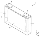
- FIG. 1 is a see-through perspective view showing one embodiment of a power storage device.
- FIG. 2 is a schematic diagram showing an embodiment of a power storage device configured by assembling a plurality of power storage elements.
- a storage element includes an electrode body having a negative electrode and a positive electrode, the negative electrode having a negative electrode active material layer containing a negative electrode active material, the negative electrode active material containing solid graphite, and the The BET specific surface area of the negative electrode active material layer is 2.1 m 2 /g or less, and the pressure applied to the electrode body is 0.1 MPa or more.
- a power storage device can suppress an increase in DC resistance after charge-discharge cycles. Although the reason why such an effect occurs is not clear, the following reason is presumed.
- the power storage element uses solid graphite, which is relatively hard to break even among graphite, as a negative electrode active material. It is possible to reduce the decrease in electronic conductivity due to material cracking and the increase in direct current resistance due to film growth on the new surface. Further, when the BET specific surface area of the negative electrode active material layer is 2.1 m 2 /g or less, the effect of suppressing an increase in DC resistance caused by contact between the surface of the negative electrode active material layer and the electrolyte can be improved.
- the pressure applied to the electrode body of 0.1 MPa or more suppresses the expansion and contraction of the negative electrode active material due to charge/discharge, thereby further reducing the increase in DC resistance after charge/discharge cycles. Therefore, it is presumed that the electric storage device can suppress an increase in DC resistance after charge-discharge cycles.
- the solid graphite in the present invention is a graphite particle having an aspect ratio (b/a) of less than 5, which is the major diameter b of the particle to the minor diameter a of the particle, and the inside of the graphite particle is clogged. It is a particle that is solid and substantially free of voids. More specifically, the term “solid” refers to the area ratio of voids in the particle to the area of the entire particle ( porosity) is 2% or less. In the present invention, graphite having an aspect ratio (b/a) of less than 5 and a porosity of more than 2% is referred to as "hollow graphite".
- Graphite particles to be measured are prepared by the following procedure. If the graphite particles or the negative electrode before assembling the electric storage element can be prepared, they are used as they are.
- the electric storage element discharged at a current of 0.1 C to the discharge cutoff voltage in normal use is disassembled in a dry air atmosphere with a dew point of ⁇ 40° C. or less, and the negative electrode is removed. After taking it out, the portion not facing the positive electrode is cut out, the adhered electrolyte and the like are washed away with dimethyl carbonate (DMC), and then dried under reduced pressure at room temperature for 24 hours to obtain a measurement sample.
- DMC dimethyl carbonate
- a sample for measurement is prepared by disassembling the electric storage element after discharge in a dry air atmosphere with a dew point of ⁇ 40° C. or less, taking out the negative electrode, cutting out the portion not facing the positive electrode, and dissolving the binder.
- the binder may be dissolved in the solvent by immersion in a solvent, the negative electrode active material and the solution containing the binder are separated by filtration, and then dried under reduced pressure at room temperature for 24 hours.
- the surface part of the measurement sample or the cross-sectional part fixed with a thermosetting resin and exposed by a cross-section polisher or the like is referred to as the "area ratio (porosity) of voids in the particle with respect to the area of the whole particle" described later.
- the "area ratio (porosity) of voids in the particles relative to the area of the entire particles" in the graphite particles can be determined by the following procedure.
- a negative electrode to be measured is fixed with a thermosetting resin.
- a cross-section polisher is used to expose the cross section of the negative electrode fixed with the resin, and a sample for measurement is prepared.
- a negative electrode to be measured is prepared by the following procedure. When the negative electrode can be prepared before assembling the electric storage element, it is used as it is. When preparing from the assembled electric storage element, first, the electric storage element is discharged at a constant current of 0.1 C to the discharge end voltage in normal use to be in a discharged state.
- the discharged storage element is disassembled, the negative electrode is taken out, and components (electrolyte, etc.) adhering to the negative electrode are thoroughly washed with dimethyl carbonate, and then dried under reduced pressure at room temperature for 24 hours.
- the work from dismantling the storage element to preparing the negative electrode to be measured is performed in a dry air atmosphere with a dew point of ⁇ 40° C. or lower.
- the term "during normal use” refers to the case where the storage element is used under the charging/discharging conditions recommended or specified for the storage element, and a charger for the storage element is provided. case, it refers to the case of using the storage device by applying the charger.
- SEM Image JSM-7001F (manufactured by JEOL Ltd.) is used as an SEM for acquisition of SEM images.
- the SEM image shall be a secondary electron image.
- the acceleration voltage is 15 kV.
- the observation magnification is set so that the number of graphite particles appearing in one field of view is 3 or more and 15 or less.
- the obtained SEM image is saved as an image file.
- various conditions such as spot diameter, working distance, irradiation current, brightness, and focus are appropriately set so that the outline of the graphite particles becomes clear.
- Clipping of Outline of Graphite Particles Using the image clipping function of image editing software Adobe Photoshop Elements 11, outlines of graphite particles are clipped from the acquired SEM image.
- This outline clipping is performed by selecting the outside of the outline of the graphite particles using the quick selection tool and editing the areas other than the graphite particles to a black background. At this time, if the number of graphite particles whose contours could be cut out is less than 3, the SEM image is obtained again, and this is repeated until the number of graphite particles whose contours can be cut out reaches 3 or more.
- the area of the high-concentration side is calculated to obtain the "area S1 of voids in the particle”.
- the image of the first graphite particle which is the same as before, is subjected to binarization processing using a density of 10% as a threshold value.
- the outer edge of the graphite particle is determined by the binarization process, and the area inside the outer edge is calculated to obtain the "area S0 of the entire particle”.
- the images of the second and subsequent graphite particles among the cut-out graphite particles are also subjected to the above-described binarization process, and the area S1 and the area S0 are calculated. Based on the calculated area S1 and area S0, the area ratios R2, R3, . (5) Determination of area ratio of voids Among all the area ratios of voids R1, R2, R3, . By calculating the average value, the "area ratio (porosity) of voids in the particles to the area of the entire particles" of the solid graphite is determined. Among all the void area ratios R1, R2, R3, .
- the above-mentioned "BET specific surface area of the negative electrode active material layer” means that the sample to be measured of the negative electrode active material layer is immersed in liquid nitrogen to cool, and nitrogen gas is supplied to physically adsorb nitrogen molecules on the particle surface. It can be obtained by measuring the pressure and the amount of nitrogen adsorption at that time. Specifically, the BET specific surface area is measured by the following method.
- the nitrogen adsorption amount (m 2 ) to the sample is determined by the one-point method using a specific surface area measuring device (trade name: MONOSORB) manufactured by Yuasa Ionics.
- a value obtained by dividing the obtained adsorption amount by the mass (g) of the sample to be measured is defined as the BET specific surface area (m 2 /g).
- a sample of the negative electrode active material layer to be measured for the BET specific surface area is prepared by the following method.
- the electric storage element is discharged at a constant current of 0.05 C to the lower limit voltage for normal use.
- the storage element is disassembled, the negative electrode is taken out as a working electrode, and a half cell is assembled using metal Li as a counter electrode.
- the potential of the working electrode is 2.0 V vs. Constant current charging is performed until Li/Li + .
- charging means applying a current so as to increase the potential of the working electrode.
- the half cell is disassembled, the working electrode is taken out, and it is thoroughly washed with dimethyl carbonate.
- the negative electrode active material layer is sampled and used as a sample to be measured. 1.00 g of the powder of the sample to be measured (negative electrode active material layer) is placed in a sample tube for measurement and dried under reduced pressure at 120° C. for 12 hours to sufficiently remove moisture in the sample to be measured.
- the process from dismantling the storage element to collecting the negative electrode active material layer is carried out in an argon atmosphere with a dew point of ⁇ 60° C. or less.
- the "pressure applied to the electrode assembly” is pressure applied in the stacking direction (Y direction in FIG. 1) of the stacked positive electrode, negative electrode, and separator. Also, the pressure applied to the electrode body is a value measured by the following method.
- a load is applied to the storage element by a pressure member or the like. It is installed in a computed tomography (CT) device. Scanning was performed along a direction parallel to the stacking direction of the electrode body (Y direction in FIG. 1), and the plane on which the load was applied to the electrode body (normally, the plane perpendicular to the stacking direction of the electrode body, the XZ plane in FIG. 1). is in direct or indirect contact with the inner surface of the container.
- CT computed tomography
- the pressure applied to the electrode assembly is 0 MPa.
- the load applied to the electrode body is measured using an autograph in the following procedure.
- the electric storage element to which a load is applied by a pressurizing member or the like is placed in the autograph so that the probe is in contact with the surface of the electrode body to which the load is applied.
- a load sufficiently smaller than the load applied by a pressure member or the like is applied to the storage element in the stacking direction of the storage element (the Y direction in FIG. 1).
- the load applied by the pressing member or the like is released.
- the amount of change in the load measured by the autograph is taken as the load applied to the electrode body.
- the pressure applied to the electrode body is obtained by dividing the load applied to the electrode body by the area of the contact surface between the container and the electrode body. Normally, a load is applied to a pair of opposing surfaces of the storage element by a pressure member or the like, and the area of only one of the pair of surfaces is the area of the surface to which the load is applied. .
- the pressure applied to the electrode body is Measure according to the following procedure. First, the storage element is discharged to the lower limit voltage for normal use with a constant current, and then installed in an X-ray CT apparatus. Scanning is performed along a direction parallel to the stacking direction of the electrode body (Y direction in FIG. 1), and at least part of a plane (XZ plane in FIG. 1) perpendicular to the stacking direction of the electrode body is directly or directly on the inner surface of the container. Check for indirect contact.
- the pressure applied to the electrode assembly is 0 MPa.
- an X-ray transmission image of the electrode body is taken and the maximum thickness in the stacking direction of the electrode body is measured. .
- the electric storage element is dismantled, the electrode body is taken out, and it is installed in the autograph so that the probe is in contact with the plane perpendicular to the stacking direction of the electrode body.
- a load is gradually applied to the surface perpendicular to the stacking direction of the electrode body, and the electrode body is compressed to the maximum thickness in the stacking direction of the electrode body measured from the X-ray transmission image.
- the load measured by the autograph is defined as the load applied to the electrode body.
- the pressure applied to the electrode body is obtained by dividing the load applied to the electrode body by the area of the contact surface between the container and the electrode body.
- a load is normally applied to a pair of opposing surfaces of the electrode assembly by the container, and the area of only one of the pair of surfaces is defined as the area of the surface to which the load is applied.
- the negative electrode active material preferably further contains flake graphite. Due to its shape, flake graphite has many contact points with other particles, so that the electrical conductivity can be improved, and the effect of suppressing the increase in DC resistance after charge-discharge cycles of the electric storage element can be further improved.
- flaky graphite refers to graphite that satisfies an aspect ratio (b/a) of 5 or more, which is the major axis b of the particle to the minor axis a of the flaky graphite particle.
- the aspect ratio of flake graphite can be measured by the same method as the aspect ratio of graphite particles described above.
- the content of the solid graphite in the negative electrode active material is preferably 50% by mass or more.
- the content of the solid graphite is 50% by mass or more, the effect of suppressing an increase in DC resistance after charge/discharge cycles of the electric storage element can be further improved.
- the difference between D90 and D10 in the particle size distribution of the negative electrode active material layer is preferably 40 ⁇ m or less.
- the difference between D90 and D10 in the particle size distribution of the negative electrode active material layer is 40 ⁇ m or less, the charge/discharge reaction becomes uniform, and local deterioration of the negative electrode active material can be suppressed. An increase in DC resistance after charge/discharge cycles can be further suppressed.
- the above “D90” is based on JIS-Z-8825 (2013), based on the particle size distribution measured by a laser diffraction/scattering method for a diluted solution in which the particles are diluted with a solvent.
- -8819-2 (2001) is a value at which the volume-based integrated distribution calculated according to 90%
- the above "D10" refers to a value at which the volume-based integrated distribution is 10%.
- each component (each component) used in each embodiment may be different from the name of each component (each component) used in the background art.
- a power storage device includes an electrode body having a positive electrode, a negative electrode, and a separator, a non-aqueous electrolyte, and a container that accommodates the electrode body and the non-aqueous electrolyte.
- the electrode body is usually a laminated type in which a plurality of positive electrodes and a plurality of negative electrodes are laminated with separators interposed therebetween, or a wound type in which positive electrodes and negative electrodes are laminated with separators interposed and wound.
- the non-aqueous electrolyte exists in a state contained in the positive electrode, the negative electrode and the separator.
- a non-aqueous electrolyte secondary battery (hereinafter also simply referred to as a “secondary battery”) will be described as an example of the storage element.
- the positive electrode has a positive electrode base material and a positive electrode active material layer arranged directly on the positive electrode base material or via an intermediate layer.
- a positive electrode base material has electroconductivity. Whether or not a material has "conductivity" is determined using a volume resistivity of 10 7 ⁇ cm as a threshold measured according to JIS-H-0505 (1975).
- the material for the positive electrode substrate metals such as aluminum, titanium, tantalum and stainless steel, or alloys thereof are used. Among these, aluminum or an aluminum alloy is preferable from the viewpoint of potential resistance, high conductivity, and cost.
- the positive electrode substrate include foil, deposited film, mesh, porous material, and the like, and foil is preferable from the viewpoint of cost. Therefore, aluminum foil or aluminum alloy foil is preferable as the positive electrode substrate. Examples of aluminum or aluminum alloys include A1085, A3003, A1N30, etc. defined in JIS-H-4000 (2014) or JIS-H4160 (2006).
- the average thickness of the positive electrode substrate is preferably 3 ⁇ m or more and 50 ⁇ m or less, more preferably 5 ⁇ m or more and 40 ⁇ m or less, even more preferably 8 ⁇ m or more and 30 ⁇ m or less, and particularly preferably 10 ⁇ m or more and 25 ⁇ m or less.
- the intermediate layer is a layer arranged between the positive electrode substrate and the positive electrode active material layer.
- the intermediate layer contains a conductive agent such as carbon particles to reduce the contact resistance between the positive electrode substrate and the positive electrode active material layer.
- the composition of the intermediate layer is not particularly limited, and includes, for example, a binder and a conductive agent.
- the positive electrode active material layer contains a positive electrode active material.
- the positive electrode active material layer contains arbitrary components such as a conductive agent, a binder (binding agent), a thickener, a filler, etc., as required.
- the positive electrode active material can be appropriately selected from known positive electrode active materials.
- a positive electrode active material for lithium ion secondary batteries a material capable of intercalating and deintercalating lithium ions is usually used.
- positive electrode active materials include lithium-transition metal composite oxides having an ⁇ -NaFeO 2 type crystal structure, lithium-transition metal composite oxides having a spinel-type crystal structure, polyanion compounds, chalcogen compounds, and sulfur.
- lithium transition metal composite oxides having an ⁇ -NaFeO 2 type crystal structure examples include Li[Li x Ni (1-x) ]O 2 (0 ⁇ x ⁇ 0.5), Li[Li x Ni ⁇ Co ( 1-x- ⁇ ) ]O 2 (0 ⁇ x ⁇ 0.5, 0 ⁇ 1), Li[Li x Co (1-x) ]O 2 (0 ⁇ x ⁇ 0.5), Li[ Li x Ni ⁇ Mn (1-x- ⁇ ) ]O 2 (0 ⁇ x ⁇ 0.5, 0 ⁇ 1), Li[Li x Ni ⁇ Mn ⁇ Co (1-x- ⁇ - ⁇ ) ] O 2 (0 ⁇ x ⁇ 0.5, 0 ⁇ , 0 ⁇ , 0.5 ⁇ + ⁇ 1), Li[Li x Ni ⁇ Co ⁇ Al (1-x- ⁇ - ⁇ ) ]O 2 ( 0 ⁇ x ⁇ 0.5, 0 ⁇ , 0 ⁇ , 0.5 ⁇ + ⁇ 1) and the like.
- lithium transition metal composite oxides having a spinel crystal structure examples include Li x Mn 2 O 4 and Li x Ni ⁇ Mn (2- ⁇ ) O 4 .
- polyanion compounds include LiFePO4 , LiMnPO4 , LiNiPO4 , LiCoPO4, Li3V2(PO4)3 , Li2MnSiO4 , Li2CoPO4F and the like.
- chalcogen compounds include titanium disulfide, molybdenum disulfide, and molybdenum dioxide.
- the atoms or polyanions in these materials may be partially substituted with atoms or anionic species of other elements. These materials may be coated with other materials on their surfaces. In the positive electrode active material layer, one kind of these materials may be used alone, or two or more kinds may be mixed and used.
- the positive electrode active material is usually particles (powder).
- the average particle size of the positive electrode active material is preferably, for example, 0.1 ⁇ m or more and 20 ⁇ m or less. By making the average particle size of the positive electrode active material equal to or more than the above lower limit, manufacturing or handling of the positive electrode active material becomes easy. By setting the average particle size of the positive electrode active material to the above upper limit or less, the electron conductivity of the positive electrode active material layer is improved. Note that when a composite of a positive electrode active material and another material is used, the average particle size of the composite is taken as the average particle size of the positive electrode active material.
- Average particle size means a value (D50) at which the volume-based integrated distribution in the particle size distribution is 50%.
- Pulverizers, classifiers, etc. are used to obtain powder with a predetermined particle size.
- Pulverization methods include, for example, methods using a mortar, ball mill, sand mill, vibrating ball mill, planetary ball mill, jet mill, counter jet mill, whirling jet mill, or sieve.
- wet pulverization in which water or an organic solvent such as hexane is allowed to coexist can also be used.
- a sieve, an air classifier, or the like is used as necessary, both dry and wet.
- the content of the positive electrode active material in the positive electrode active material layer is preferably 50% by mass or more and 99% by mass or less, more preferably 70% by mass or more and 98% by mass or less, and even more preferably 80% by mass or more and 95% by mass or less.
- the conductive agent is not particularly limited as long as it is a conductive material.
- Examples of such conductive agents include carbonaceous materials, metals, and conductive ceramics.
- Carbonaceous materials include graphite, non-graphitic carbon, graphene-based carbon, and the like.
- Examples of non-graphitic carbon include carbon nanofiber, pitch-based carbon fiber, and carbon black.
- Examples of carbon black include furnace black, acetylene black, and ketjen black.
- Graphene-based carbon includes graphene, carbon nanotube (CNT), fullerene, and the like.
- the shape of the conductive agent may be powdery, fibrous, or the like.
- As the conductive agent one type of these materials may be used alone, or two or more types may be mixed and used. Also, these materials may be combined for use.
- a composite material of carbon black and CNT may be used.
- carbon black is preferable from the viewpoint of electron conductivity and coatability
- acetylene black is particularly preferable
- the content of the conductive agent in the positive electrode active material layer is preferably 1% by mass or more and 10% by mass or less, more preferably 3% by mass or more and 9% by mass or less.
- Binders include, for example, fluorine resins (polytetrafluoroethylene (PTFE), polyvinylidene fluoride (PVDF), etc.), thermoplastic resins such as polyethylene, polypropylene, polyacryl, and polyimide; ethylene-propylene-diene rubber (EPDM), sulfone Elastomers such as modified EPDM, styrene-butadiene rubber (SBR) and fluororubber; polysaccharide polymers and the like.
- fluorine resins polytetrafluoroethylene (PTFE), polyvinylidene fluoride (PVDF), etc.
- thermoplastic resins such as polyethylene, polypropylene, polyacryl, and polyimide
- EPDM ethylene-propylene-diene rubber
- SBR styrene-butadiene rubber
- fluororubber polysaccharide polymers and the like.
- the content of the binder in the positive electrode active material layer is preferably 1% by mass or more and 10% by mass or less, more preferably 2% by mass or more and 9% by mass or less.
- thickeners examples include polysaccharide polymers such as carboxymethylcellulose (CMC) and methylcellulose.
- CMC carboxymethylcellulose
- methylcellulose examples include polysaccharide polymers such as carboxymethylcellulose (CMC) and methylcellulose.
- the functional group may be previously deactivated by methylation or the like.
- the filler is not particularly limited.
- Fillers include polyolefins such as polypropylene and polyethylene, inorganic oxides such as silicon dioxide, alumina, titanium dioxide, calcium oxide, strontium oxide, barium oxide, magnesium oxide and aluminosilicate, magnesium hydroxide, calcium hydroxide, hydroxide Hydroxides such as aluminum, carbonates such as calcium carbonate, sparingly soluble ionic crystals such as calcium fluoride, barium fluoride, and barium sulfate, nitrides such as aluminum nitride and silicon nitride, talc, montmorillonite, boehmite, zeolite, Mineral resource-derived substances such as apatite, kaolin, mullite, spinel, olivine, sericite, bentonite, and mica, or artificial products thereof may be used.
- the positive electrode active material layer contains typical nonmetallic elements such as B, N, P, F, Cl, Br, and I, Li, Na, Mg, Al, K, Ca, Zn, Ga, Ge, Sn, Sr, Ba, and the like.
- typical metal elements, transition metal elements such as Sc, Ti, V, Cr, Mn, Fe, Co, Ni, Cu, Mo, Zr, Nb, W are used as positive electrode active materials, conductive agents, binders, thickeners, fillers It may be contained as a component other than
- the negative electrode has a negative electrode base material and a negative electrode active material layer disposed directly on the negative electrode base material or via an intermediate layer.
- the structure of the intermediate layer is not particularly limited, and can be selected from, for example, the structures exemplified for the positive electrode.
- the negative electrode base material has conductivity.
- materials for the negative electrode substrate metals such as copper, nickel, stainless steel, nickel-plated steel, alloys thereof, carbonaceous materials, and the like are used. Among these, copper or a copper alloy is preferred.
- the negative electrode substrate include foil, deposited film, mesh, porous material, and the like, and foil is preferable from the viewpoint of cost. Therefore, copper foil or copper alloy foil is preferable as the negative electrode substrate.
- Examples of copper foil include rolled copper foil and electrolytic copper foil.
- the average thickness of the negative electrode substrate is preferably 2 ⁇ m or more and 35 ⁇ m or less, more preferably 3 ⁇ m or more and 30 ⁇ m or less, even more preferably 4 ⁇ m or more and 25 ⁇ m or less, and particularly preferably 5 ⁇ m or more and 20 ⁇ m or less.
- the negative electrode active material layer contains a negative electrode active material.
- the negative electrode active material layer contains arbitrary components such as a conductive agent, a binder, a thickener, a filler, etc., as required.
- Optional components such as conductive agents, binders, thickeners, and fillers can be selected from the materials exemplified for the positive electrode.
- the negative electrode active material layer contains typical nonmetallic elements such as B, N, P, F, Cl, Br, and I, Li, Na, Mg, Al, K, Ca, Zn, Ga, Ge, Sn, Sr, Ba, and the like. and transition metal elements such as Sc, Ti, V, Cr, Mn, Fe, Co, Ni, Cu, Mo, Zr, Ta, Hf, Nb, and W are used as negative electrode active materials, conductive agents, binders, and thickeners. You may contain as a component other than a sticky agent and a filler.
- the negative electrode active material contains solid graphite.
- solid graphite which is relatively hard to break even among graphites, cracking of the negative electrode active material is less likely to occur even if the negative electrode active material expands and shrinks during charging and discharging, and the electronic conductivity associated with cracking is reduced. An increase in DC resistance due to a drop can be reduced.
- the area ratio (porosity) of the voids in the particles to the area of the entire particles in the cross section of the solid graphite observed in the above SEM image is 2% or less, more preferably 1.5% or less, and 1% or less. is more preferred.
- the lower limit of this area ratio (void ratio) may be 0% or 0.1%.
- the solid graphite may be natural graphite or artificial graphite, but is preferably artificial graphite.
- artificial graphite is a general term for graphite artificially produced by heat-treating a raw material such as coke to graphitize it.
- the artificial graphite may have two peaks in a diffraction angle 2 ⁇ range of 40° to 50° in an X-ray diffraction pattern using CuK ⁇ rays measured before charging/discharging or in a discharged state. These two peaks are supposed to be derived from the hexagonal structure. In the case of natural graphite, two peaks derived from the hexagonal structure and two peaks derived from the rhombohedral structure generally appear in the diffraction angle 2 ⁇ range of 40° to 50°. It is
- the lower limit of the average particle size (D50) of the solid graphite is preferably 8 ⁇ m, more preferably 10 ⁇ m in some cases, more preferably 12 ⁇ m, still more preferably 14 ⁇ m, and even more preferably 16 ⁇ m.
- the upper limit of the average particle size (D50) of the solid graphite is preferably 25 ⁇ m, more preferably 22 ⁇ m, and more preferably 20 ⁇ m in some cases.
- the negative electrode active material may contain a negative electrode active material other than solid graphite.
- negative electrode active materials include metal Li; metals or semimetals such as Si and Sn; metal oxides and semimetal oxides such as Si oxide, Ti oxide and Sn oxide; Titanium-containing oxides such as O 12 , LiTiO 2 , TiNb 2 O 7 ; polyphosphate compounds; silicon carbide; graphite other than solid graphite (graphite), non-graphitizable carbon (easily graphitizable carbon or non-graphitizable carbon ) and other carbon materials.
- one type of these materials may be used alone, or two or more types may be mixed and used.
- graphite other than solid graphite is preferable, flake graphite and hollow graphite are preferable, and flake graphite is more preferable. Due to its shape, flake graphite has many contact points with other particles, so that the electrical conductivity can be improved, and the effect of suppressing the increase in DC resistance after charge-discharge cycles of the electric storage element can be further improved.
- Graphite refers to a carbon material having an average lattice spacing (d 002 ) of the (002) plane of 0.33 nm or more and less than 0.34 nm as determined by X-ray diffraction before charging/discharging or in a discharged state.
- the discharged state means a state in which the carbon material, which is the negative electrode active material, is discharged such that lithium ions that can be inserted and released are sufficiently released during charging and discharging.
- the open circuit voltage is 0.7 V or higher.
- the negative electrode active material is usually particles (powder).
- the average particle size (D50) of the negative electrode active material other than the solid graphite can be, for example, 1 nm or more and 100 ⁇ m or less.
- the average particle size thereof may be 1 ⁇ m or more and 100 ⁇ m or less.
- the other negative electrode active material is Si, Sn, Si oxide, Sn oxide, or the like, the average particle size thereof may be 1 nm or more and 1 ⁇ m or less.
- the electronic conductivity of the active material layer is improved by setting the average particle size of the other negative electrode active material to the above upper limit or less.
- a pulverizer, a classifier, or the like is used to obtain powder having a predetermined particle size.
- the pulverization method and classification method can be selected from, for example, the methods exemplified for the positive electrode.
- the lower limit of the content of the solid graphite in the negative electrode active material is preferably 40% by mass, more preferably 45% by mass, more preferably 50% by mass, 55% by mass, 58% by mass, or 60% by mass. % by mass is more preferred, 65% by mass is even more preferred, and 70% by mass is particularly preferred. When the content of the solid graphite is equal to or higher than the lower limit, the effect of suppressing an increase in DC resistance after charge-discharge cycles of the electric storage element can be further improved.
- the upper limit of the solid graphite content is not particularly limited, and may be 100% by mass, 90% by mass, 88% by mass, 85% by mass, or 82% by mass. may be 80% by mass.
- the upper limit of the content of flake graphite in the negative electrode active material is preferably 20% by mass, and more preferably 18% by mass, 15% by mass, and 12% by mass. In some cases, 10% by weight is more preferred.
- the content of the negative electrode active material in the negative electrode active material layer is preferably 60% by mass or more and 99% by mass or less, more preferably 90% by mass or more and 98% by mass or less.
- the upper limit of the BET specific surface area of the negative electrode active material layer is 2.1 m 2 /g or less, preferably 2.0 m 2 /g, more preferably 1.9 m 2 /g in some cases, and 1.8 m 2 /g. g.
- the lower limit of the BET specific surface area of the negative electrode active material layer is preferably 1.0 m 2 /g, more preferably 1.2 m 2 /g, and more preferably 1.5 m 2 /g.
- the upper limit of the difference between D90 and D10 in the particle size distribution of the negative electrode active material layer is preferably 40 ⁇ m, more preferably 38 ⁇ m.
- the lower limit of the difference between D90 and D10 in the particle size distribution of the negative electrode active material layer is preferably 25 ⁇ m, more preferably 30 ⁇ m.
- the separator can be appropriately selected from known separators.
- a separator consisting of only a substrate layer, a separator having a heat-resistant layer containing heat-resistant particles and a binder formed on one or both surfaces of a substrate layer, or the like can be used.
- Examples of the form of the base material layer of the separator include woven fabric, non-woven fabric, porous resin film, and the like. Among these forms, a porous resin film is preferred from the viewpoint of strength, and a non-woven fabric is preferred from the viewpoint of non-aqueous electrolyte retention.
- polyolefins such as polyethylene and polypropylene are preferable from the viewpoint of shutdown function, and polyimide, aramid, and the like are preferable from the viewpoint of oxidative decomposition resistance.
- a material obtained by combining these resins may be used as the base material layer of the separator.
- the heat-resistant particles contained in the heat-resistant layer preferably have a mass loss of 5% or less when the temperature is raised from room temperature to 500 ° C. in an air atmosphere of 1 atm, and the mass loss when the temperature is raised from room temperature to 800 ° C. is more preferably 5% or less.
- An inorganic compound can be mentioned as a material whose mass reduction is less than or equal to a predetermined value. Examples of inorganic compounds include oxides such as iron oxide, silicon oxide, aluminum oxide, titanium oxide, zirconium oxide, calcium oxide, strontium oxide, barium oxide, magnesium oxide, and aluminosilicate; nitrides such as aluminum nitride and silicon nitride.
- carbonates such as calcium carbonate
- sulfates such as barium sulfate
- sparingly soluble ionic crystals such as calcium fluoride, barium fluoride, and barium titanate
- covalent crystals such as silicon and diamond
- Mineral resource-derived substances such as zeolite, apatite, kaolin, mullite, spinel, olivine, sericite, bentonite, and mica, or artificial products thereof.
- the inorganic compound a single substance or a composite of these substances may be used alone, or two or more of them may be mixed and used.
- silicon oxide, aluminum oxide, or aluminosilicate is preferable from the viewpoint of the safety of the electric storage device.
- the porosity of the separator is preferably 80% by volume or less from the viewpoint of strength, and preferably 20% by volume or more from the viewpoint of discharge performance.
- the "porosity” is a volume-based value and means a value measured with a mercury porosimeter.
- a polymer gel composed of a polymer and a non-aqueous electrolyte may be used as the separator.
- examples of polymers include polyacrylonitrile, polyethylene oxide, polypropylene oxide, polymethyl methacrylate, polyvinyl acetate, polyvinylpyrrolidone, polyvinylidene fluoride, and the like.
- the use of polymer gel has the effect of suppressing liquid leakage.
- a polymer gel may be used in combination with the porous resin film or non-woven fabric as described above.
- the electrode body is in a state where a load is applied in all states from SOC 0% to SOC 100%.
- a load is applied to the electrode assembly in the thickness direction of the laminated positive electrode, negative electrode, and separator, that is, in the lamination direction.
- the electrode body may have a portion where no load is applied, such as an end portion of the electrode body. In the secondary battery, since the load is applied to the electrode body in this way, it is possible to suppress an increase in the direct current resistance after the charge/discharge cycles.
- the lower limit of the pressure applied to the electrode body is 0.1 MPa, preferably 0.15 MPa, and more preferably 0.2 MPa.
- the upper limit of the pressure applied to the electrode body is preferably 2.0 MPa, more preferably 1.0 MPa.
- Non-aqueous electrolyte The non-aqueous electrolyte can be appropriately selected from known non-aqueous electrolytes. A non-aqueous electrolyte may be used as the non-aqueous electrolyte.
- the non-aqueous electrolyte contains a non-aqueous solvent and an electrolyte salt dissolved in this non-aqueous solvent.
- the non-aqueous solvent can be appropriately selected from known non-aqueous solvents.
- Non-aqueous solvents include cyclic carbonates, chain carbonates, carboxylic acid esters, phosphoric acid esters, sulfonic acid esters, ethers, amides, nitriles and the like.
- the non-aqueous solvent those in which some of the hydrogen atoms contained in these compounds are substituted with halogens may be used.
- Cyclic carbonates include ethylene carbonate (EC), propylene carbonate (PC), butylene carbonate (BC), vinylene carbonate (VC), vinylethylene carbonate (VEC), chloroethylene carbonate, fluoroethylene carbonate (FEC), and difluoroethylene carbonate. (DFEC), styrene carbonate, 1-phenylvinylene carbonate, 1,2-diphenylvinylene carbonate and the like. Among these, EC is preferred.
- chain carbonates examples include diethyl carbonate (DEC), dimethyl carbonate (DMC), ethylmethyl carbonate (EMC), diphenyl carbonate, trifluoroethylmethyl carbonate, bis(trifluoroethyl) carbonate, and the like. Among these, EMC is preferred.
- the non-aqueous solvent it is preferable to use a cyclic carbonate or a chain carbonate, and it is more preferable to use a combination of a cyclic carbonate and a chain carbonate.
- a cyclic carbonate it is possible to promote the dissociation of the electrolyte salt and improve the ionic conductivity of the non-aqueous electrolyte.
- a chain carbonate By using a chain carbonate, the viscosity of the non-aqueous electrolyte can be kept low.
- the volume ratio of the cyclic carbonate to the chain carbonate is preferably in the range of, for example, 5:95 to 50:50.
- the electrolyte salt can be appropriately selected from known electrolyte salts.
- electrolyte salts include lithium salts, sodium salts, potassium salts, magnesium salts, onium salts and the like. Among these, lithium salts are preferred.
- Lithium salts include inorganic lithium salts such as LiPF 6 , LiPO 2 F 2 , LiBF 4 , LiClO 4 and LiN(SO 2 F) 2 , lithium bis(oxalate) borate (LiBOB), lithium difluorooxalate borate (LiFOB).
- lithium oxalate salts such as lithium bis(oxalate) difluorophosphate ( LiFOP ), LiSO3CF3 , LiN ( SO2CF3 ) 2 , LiN ( SO2C2F5 ) 2 , LiN ( SO2CF3 ) (SO 2 C 4 F 9 ), LiC(SO 2 CF 3 ) 3 , LiC(SO 2 C 2 F 5 ) 3 and other lithium salts having a halogenated hydrocarbon group.
- inorganic lithium salts are preferred, and LiPF6 is more preferred.
- the content of the electrolyte salt in the non-aqueous electrolyte is preferably 0.1 mol/dm3 or more and 2.5 mol/dm3 or less , and 0.3 mol/dm3 or more and 2.0 mol/dm3 or less at 20 °C and 1 atm. It is more preferably 3 or less, more preferably 0.5 mol/dm 3 or more and 1.7 mol/dm 3 or less, and particularly preferably 0.7 mol/dm 3 or more and 1.5 mol/dm 3 or less.
- the non-aqueous electrolyte may contain additives in addition to the non-aqueous solvent and electrolyte salt.
- additives include oxalates such as lithium bis(oxalate)borate (LiBOB), lithium difluorooxalateborate (LiFOB), lithium bis(oxalate)difluorophosphate (LiFOP); lithium bis(fluorosulfonyl)imide ( LiFSI) and other imide salts; biphenyl, alkylbiphenyl, terphenyl, partially hydrogenated terphenyl, cyclohexylbenzene, t-butylbenzene, t-amylbenzene, diphenyl ether, dibenzofuran and other aromatic compounds; 2-fluorobiphenyl, Partial halides of the above aromatic compounds such as o-cyclohexylfluorobenzene and p-cyclohexylfluorobenzene; 2,4
- the content of the additive contained in the non-aqueous electrolyte is preferably 0.01% by mass or more and 10% by mass or less, and 0.1% by mass or more and 7% by mass or less with respect to the total mass of the non-aqueous electrolyte. More preferably, it is 0.2% by mass or more and 5% by mass or less, and particularly preferably 0.3% by mass or more and 3% by mass or less.
- a solid electrolyte may be used as the non-aqueous electrolyte, or a non-aqueous electrolyte and a solid electrolyte may be used together.
- the solid electrolyte can be selected from any material that has ion conductivity, such as lithium, sodium, and calcium, and is solid at room temperature (for example, 15°C to 25°C).
- Examples of solid electrolytes include sulfide solid electrolytes, oxide solid electrolytes, oxynitride solid electrolytes, polymer solid electrolytes, gel polymer electrolytes, and the like.
- Examples of sulfide solid electrolytes for lithium ion secondary batteries include Li 2 SP 2 S 5 , LiI—Li 2 SP 2 S 5 and Li 10 Ge—P 2 S 12 .
- the shape of the electric storage element of this embodiment is not particularly limited, and examples thereof include cylindrical batteries, rectangular batteries, flat batteries, coin batteries, button batteries, and the like.
- Fig. 1 shows a power storage element 1 as an example of a square battery.
- An electrode body 2 having a positive electrode and a negative electrode wound with a separator sandwiched therebetween is housed in a rectangular container 3 .
- the positive electrode is electrically connected to the positive electrode terminal 4 via a positive electrode lead 41 .
- the negative electrode is electrically connected to the negative terminal 5 via a negative lead 51 .
- a load can be applied to the electrode body 2 in the electric storage element 1 of FIG. 1, for example, by a pressure member (not shown) that presses the container 3 from the outside.
- the pressurizing member may be a restraining member that restrains the shape of the container 3 .
- the pressurizing member (restraining member) sandwiches the electrode body 2 from both sides (the front side surface and the back side surface in FIG. 1) in the stacking direction (the Y direction in FIG. 1) through the container 3, for example, and pressurizes it.
- Both surfaces of the electrode body 2 are in contact with the inner surface of the container 3 directly or via another member (not shown). Therefore, a load is applied to the electrode body 2 by pressurizing the container 3 .
- Both surfaces of the electrode body 2 are preferably in contact with the inner surface of the container 3 directly or via another member (not shown) when the container 3 is not pressurized.
- the pressing member restraining member
- examples of the pressing member include a restraining band and a metal frame.
- FIG. 2 which will be described later, a plurality of storage elements 1 are arranged side by side in the stacking direction of the electrode body 2 (the Y direction in FIG. 1 and the left-right direction in FIG. 2). 1 may be fixed using a restraining member 21 such as a frame while being pressurized.
- the power storage device of the present embodiment is a power source for automobiles such as electric vehicles (EV), hybrid vehicles (HEV), and plug-in hybrid vehicles (PHEV), power sources for electronic devices such as personal computers and communication terminals, or power sources for power storage.
- EV electric vehicles
- HEV hybrid vehicles
- PHEV plug-in hybrid vehicles
- power sources for electronic devices such as personal computers and communication terminals
- power sources for power storage
- it can be mounted as a power storage unit (battery module) configured by assembling a plurality of power storage elements 1 .
- the technology of the present invention may be applied to at least one power storage element included in the power storage unit.
- FIG. 2 shows an example of a power storage device 30 in which power storage units 20 each including two or more electrically connected power storage elements 1 are assembled.
- the power storage unit 20 is configured such that a plurality of power storage elements 1 are arranged without gaps in the stacking direction, the thickness is kept constant by the fixed-size constraining member 21, and pressure is applied from the stacking direction (horizontal direction in FIG. 2). is constrained by
- the power storage device 30 may include a bus bar (not shown) that electrically connects two or more power storage elements 1, a bus bar (not shown) that electrically connects two or more power storage units 20, and the like.
- the power storage unit 20 or power storage device 30 may include a state monitoring device (not shown) that monitors the state of one or more power storage elements.
- a method for manufacturing the electric storage device of the present embodiment can be appropriately selected from known methods.
- the manufacturing method includes, for example, preparing an electrode body, preparing a non-aqueous electrolyte, and housing the electrode body and the non-aqueous electrolyte in a container.
- Preparing the electrode body includes preparing a positive electrode and a negative electrode, and forming the electrode body by laminating or winding the positive electrode and the negative electrode with a separator interposed therebetween.
- Containing the non-aqueous electrolyte in the container can be appropriately selected from known methods.
- the non-aqueous electrolyte may be injected through an inlet formed in the container, and then the inlet may be sealed.
- the method for manufacturing the electric storage element may further comprise attaching a pressing member such as a restraining member. Further, the method for manufacturing a power storage device having a plurality of power storage elements may include attaching a pressing member such as a restraining member to the plurality of power storage elements.
- the electric storage device of the present invention is not limited to the above-described embodiments, and various modifications may be made without departing from the gist of the present invention.
- the configuration of another embodiment can be added to the configuration of one embodiment, and part of the configuration of one embodiment can be replaced with the configuration of another embodiment or a known technique.
- some of the configurations of certain embodiments can be deleted.
- well-known techniques can be added to the configuration of a certain embodiment.
- the storage element is used as a chargeable/dischargeable non-aqueous electrolyte secondary battery (for example, a lithium ion secondary battery), but the type, shape, size, capacity, etc. of the storage element are arbitrary. .
- the present invention can also be applied to capacitors such as various secondary batteries, electric double layer capacitors, and lithium ion capacitors.
- the electrode body in which the positive electrode and the negative electrode are laminated with a separator interposed therebetween has been described, but the electrode body does not have to have a separator.
- the positive electrode and the negative electrode may be in direct contact with each other in a state in which a layer having no conductivity is formed on the active material layer of the positive electrode or the negative electrode.
- Example 1 (Preparation of negative electrode) Solid graphite, hollow graphite, and flake graphite listed in Table 1 as negative electrode active materials, styrene-butadiene rubber (SBR) as a binder, carboxymethyl cellulose (CMC) as a thickener, and water as a dispersion medium. were mixed to prepare a negative electrode mixture paste (a material for forming a negative electrode active material layer).
- SBR styrene-butadiene rubber
- CMC carboxymethyl cellulose
- water a dispersion medium.
- a negative electrode mixture paste a material for forming a negative electrode active material layer
- As the solid graphite artificial graphite having the porosity described in Table 1 and having an aspect ratio of less than 5 is used. Natural graphite was used. The aspect ratio of flake graphite was 5 or more.
- the porosity of artificial graphite, natural graphite, and flake graphite is a value measured by the method described above after separately preparing a negative electrode containing only artificial graphite, only natural graphite, or only flake graphite as the negative electrode active material.
- the mass ratio of the negative electrode active material, the binder, and the thickener was 97:2:1 (in terms of solid content).
- the negative electrode mixture paste was prepared through a kneading process using a multi-blender mill after adjusting the viscosity by adjusting the amount of water.
- a negative electrode mixture paste was applied to both sides of a copper foil as a negative electrode base material and dried. After that, roll pressing was performed to obtain a negative electrode.
- D10 and D90 in the particle size distribution of the negative electrode active material measured by the above method are 9.1 ⁇ m and 53.8 ⁇ m, respectively, and the BET specific surface area of the negative electrode active material layer measured by the above method is 2.0 m 2 / was g.
- Non-aqueous electrolyte LiPF6 was dissolved at a concentration of 1.2 mol/dm3 in a solvent in which ethylene carbonate (EC), dimethyl carbonate (DMC) and ethyl methyl carbonate (EMC) were mixed at a volume ratio of 30:35:35 , and a non-aqueous An electrolyte was obtained.
- EC ethylene carbonate
- DMC dimethyl carbonate
- EMC ethyl methyl carbonate
- An electrode body was obtained by laminating the positive electrode, the negative electrode, and the separator.
- the electrode assembly was enclosed in a container formed from a metal-resin composite film, and a non-aqueous electrolyte was injected into the container, followed by sealing.
- a constraining member was attached from both sides of the container to constrain the container to a constant size in the stacking direction, and a load was applied so that the pressure applied to the electrode assembly was 0.1 MPa.
- Example 2 and Comparative Examples 1 to 8 In the same manner as in Example 1, except that the materials listed in Table 1 were used as the negative electrode active material, and the content ratio of the negative electrode active material and the pressure applied to the electrode body were changed as shown in Table 2, Example 2 and Comparative Example 2 were prepared. Each electric storage device of Example 1 to Comparative Example 8 was obtained. Table 2 shows the D10 and D90 in the particle size distribution of the negative electrode active material layer of each storage element, and the BET specific surface area.
- the batteries After being stored in a constant temperature bath at 25° C. for 3 hours or longer, the batteries were discharged at currents of 0.2 C, 0.5 C and 1.0 C in this order for 30 seconds each. After completion of each discharge, constant current charging was performed at a current of 0.2 C to bring the SOC to 50%. The relationship between the current in each discharge and the voltage at 10 seconds after the start of discharge was plotted, and the direct current resistance was obtained from the slope of the straight line obtained from the three-point plot, and was taken as the initial direct current resistance.
- the negative electrode active material contains solid graphite, the BET specific surface area of the negative electrode active material layer is 2.1 m 2 /g or less, and the pressure applied to the electrode body is 0.1 MPa or more. It can be seen that in Examples 1 and 2, where . In particular, Example 2, in which the content of solid graphite is 50% by mass or more, and the difference between D90 and D10 in the particle size distribution of the negative electrode active material layer is 40 ⁇ m or less, does not cause an increase in DC resistance after charge-discharge cycles. The inhibitory effect was excellent.
- Comparative Examples 1 to 8 in which the BET specific surface area of the negative electrode active material layer is 2.1 m 2 /g or less and the pressure applied to the electrode body is not 0.1 MPa or more, the DC resistance after the charge-discharge cycle does not increase. It can be seen that the inhibitory effect is low.
- the BET specific surface area of the negative electrode active material layer is more than 2.1 m 2 /g, the pressure applied to the electrode body is less than 0.1 MPa, and the content of solid graphite is less than 50% by mass.
- Comparative Example 1 in which the difference between D90 and D10 in the particle size distribution of the substance layer exceeded 40 ⁇ m, the rate of increase in DC resistance after charge-discharge cycles was high.
- Example 3 (Preparation of negative electrode) Solid graphite and flake graphite listed in Table 3 as negative electrode active materials, styrene-butadiene rubber (SBR) as a binder, carboxymethyl cellulose (CMC) as a thickener, and water as a dispersion medium were mixed. A negative electrode mixture paste (a material for forming a negative electrode active material layer) was prepared. As solid graphite, artificial graphite having a porosity shown in Table 3 and an aspect ratio of less than 5 was used. The aspect ratio of flake graphite was 5 or more.
- SBR styrene-butadiene rubber
- CMC carboxymethyl cellulose
- the porosity of artificial graphite and flake graphite is a value measured by the method described above after separately preparing a negative electrode containing only artificial graphite or only flake graphite as a negative electrode active material.
- the mass ratio of the negative electrode active material, the binder, and the thickener was 97:2:1 (in terms of solid content).
- the negative electrode mixture paste was prepared through a kneading process using a multi-blender mill after adjusting the viscosity by adjusting the amount of water.
- a negative electrode mixture paste was applied to both sides of a copper foil as a negative electrode base material and dried. After that, roll pressing was performed to obtain a negative electrode.
- D10 and D90 in the particle size distribution of the negative electrode active material measured by the above method are 6.7 ⁇ m and 31.6 ⁇ m, respectively, and the BET specific surface area of the negative electrode active material layer measured by the above method is 2.0 m 2 / was g.
- Non-aqueous electrolyte LiPF6 was dissolved at a concentration of 1.2 mol/dm3 in a solvent in which ethylene carbonate (EC), dimethyl carbonate (DMC) and ethyl methyl carbonate (EMC) were mixed at a volume ratio of 30:35:35 , and a non-aqueous An electrolyte was obtained.
- EC ethylene carbonate
- DMC dimethyl carbonate
- EMC ethyl methyl carbonate
- An electrode body was obtained by laminating the positive electrode, the negative electrode, and the separator.
- the electrode assembly was enclosed in a container formed from a metal-resin composite film, and a non-aqueous electrolyte was injected into the container, followed by sealing.
- a constraining member was attached from both sides of the container to constrain the container in a constant size in the stacking direction, and a load was applied so that the pressure applied to the electrode assembly was 0.1 MPa.
- Comparative Examples 9 to 11 In the same manner as in Example 3, except that the materials listed in Table 3 were used as the negative electrode active materials, and the content ratio of the negative electrode active materials and the pressure applied to the electrode body were changed as shown in Table 4, Comparative Examples 9 and 9 were compared. Each electric storage device of Example 11 was obtained. Table 4 shows the D10 and D90 in the particle size distribution of the negative electrode active material layer of each storage element, and the BET specific surface area. In Comparative Examples 9 and 10, in addition to solid graphite and flake graphite, natural graphite having a porosity shown in Table 3 and an aspect ratio of less than 5 was used as hollow graphite as the negative electrode active material. Using.
- Example 3 and Comparative Example 9 in the same procedure as in (1-1) to (1-4) above, except that the conditions of the charge-discharge cycle test in (1-3) above were changed as follows. , the rate of increase in DC resistance after charge-discharge cycles in each storage element of Comparative Example 11 was obtained.
- the conditions of the charge/discharge cycle test are as follows. At 45.degree. The termination condition of charging was until the total charging time reached 3 hours. A rest period of 10 minutes was then provided. At a discharge current of 1.0 C, an amount of electricity equivalent to 85% of the discharge capacity in the initial charge/discharge was discharged at a constant current, and then a rest period of 10 minutes was provided. 700 cycles were carried out with this charging and discharging process as one cycle.
- Table 4 shows the DC resistance increase rate at 25° C. after charge/discharge cycles in each of the storage elements of Example 3 and Comparative Examples 9 to 11.
- the negative electrode active material contains solid graphite, the BET specific surface area of the negative electrode active material layer is 2.1 m 2 /g or less, and the pressure applied to the electrode body is 0.1 MPa or more. It can be seen that in Example 3 as well, the increase in the DC resistance of the electric storage element after the charge/discharge cycle is suppressed.
- Comparative Examples 9 to 11 in which the BET specific surface area of the negative electrode active material layer is 2.1 m 2 /g or less and the pressure applied to the electrode body is not 0.1 MPa or more, the increase in DC resistance after charge-discharge cycles is reduced. It can be seen that the inhibitory effect is low. Surprisingly, when comparing Comparative Examples 9 and 11, in which no pressure was applied to the electrode body, the charge/discharge performance was better in Comparative Example 11, in which the BET specific surface area of the negative electrode active material layer was 2.1 m 2 /g or less.
- Example 3 Comparing Comparative Example 10 and Example 3, in which the pressure applied to the electrode body was 0.1 MPa or more while the DC resistance after the cycle increased, the BET specific surface area of the negative electrode active material layer was 2.1 m 2 / It can be seen that in Example 3, where the value is g or less, the increase in the DC resistance of the electric storage element after charge-discharge cycles is remarkably suppressed.
- the power storage device can suppress an increase in DC resistance after charge-discharge cycles.
- the present invention can be applied to personal computers, electronic devices such as communication terminals, and electric storage elements used as power sources for automobiles and the like.
Abstract
Description
(1)測定用試料の準備
測定対象とする負極を熱硬化性の樹脂で固定する。樹脂で固定された負極について、クロスセクション・ポリッシャを用いることで、断面を露出させ、測定用試料を作製する。なお、測定対象とする負極は、下記の手順により準備する。蓄電素子を組み立て前の負極が準備できる場合には、そのまま用いる。組み立て後の蓄電素子から準備する場合には、まず蓄電素子を、0.1Cの電流で、通常使用時の放電終止電圧まで定電流放電し、放電された状態とする。この放電された状態の蓄電素子を解体し、負極を取り出して、ジメチルカーボネートにより負極に付着した成分(電解質等)を充分に洗浄した後、室温にて24時間減圧乾燥を行う。蓄電素子の解体から測定対象とする負極の準備までの作業は、露点-40℃以下の乾燥空気雰囲気中で行う。ここで、通常使用時とは、当該蓄電素子について推奨され、又は指定される充放電条件を採用して当該蓄電素子を使用する場合であり、当該蓄電素子のための充電器が用意されている場合は、その充電器を適用して当該蓄電素子を使用する場合をいう。
(2)SEM像の取得
SEM像の取得には、SEMとしてJSM-7001F(日本電子株式会社製)を用いる。SEM像は、二次電子像を観察するものとする。加速電圧は、15kVとする。観察倍率は、一視野に現れる黒鉛粒子が3個以上15個以内となる倍率に設定する。得られたSEM像は、画像ファイルとして保存する。その他、スポット径、ワーキングディスタンス、照射電流、輝度、フォーカス等の諸条件は、黒鉛粒子の輪郭が明瞭になるように適宜設定する。
(3)黒鉛粒子の輪郭の切り抜き
画像編集ソフトAdobe Photoshop Elements 11の画像切り抜き機能を用いて、取得したSEM像から黒鉛粒子の輪郭を切り抜く。この輪郭の切り抜きは、クイック選択ツールを用いて黒鉛粒子の輪郭より外側を選択し、黒鉛粒子以外を黒背景へと編集して行う。このとき、輪郭を切り抜くことができた黒鉛粒子が3個未満であった場合は、再度、SEM像を取得し、輪郭を切り抜くことができた黒鉛粒子が3個以上になるまで行う。
(4)二値化処理
切り抜いた黒鉛粒子のうち1つ目の黒鉛粒子の画像について、画像解析ソフトPopImaging 6.00を用い、強度が最大となる濃度から20%分小さい濃度を閾値に設定して二値化処理を行う。二値化処理により、濃度の高い側の面積を算出することで「粒子内の空隙の面積S1」とする。
ついで、先ほどと同じ1つ目の黒鉛粒子の画像について、濃度10%を閾値として二値化処理を行う。二値化処理により、黒鉛粒子の外縁を決定し、当該外縁の内側の面積を算出することで、「粒子全体の面積S0」とする。
上記算出したS1及びS0を用いて、S0に対するS1の比(S1/S0)を算出することにより、1つ目の黒鉛粒子における「粒子全体の面積に対する粒子内の空隙の面積率R1」を算出する。
切り抜いた黒鉛粒子のうち2つ目以降の黒鉛粒子の画像についても、それぞれ、上記の二値化処理を行い、面積S1、面積S0を算出する。この算出した面積S1、面積S0に基づいて、それぞれの黒鉛粒子の空隙の面積率R2、R3、・・・を算出する。
(5)空隙の面積率の決定
二値化処理により算出した全ての空隙の面積率R1、R2、R3、・・・のうち、空隙の面積率Rnが2%以下の数値を抽出し、その平均値を算出することにより、中実黒鉛の「粒子全体の面積に対する粒子内の空隙の面積率(空隙率)」を決定する。二値化処理により算出した全ての空隙の面積率R1、R2、R3、・・・のうち、空隙の面積率Rnが2%超の数値を抽出し、その平均値を算出することにより、中空黒鉛の「粒子全体の面積に対する粒子内の空隙の面積率(空隙率)」を決定する。
なお、上記「SEM像の取得」に用いる走査型電子顕微鏡、「黒鉛粒子の輪郭の切り抜き」に用いる画像編集ソフト、及び「二値化処理」に用いる画像解析ソフトに代えて、これらと同等の測定、画像編集及び画像解析が可能な装置及びソフトウェア等を用いてもよい。 The "area ratio (porosity) of voids in the particles relative to the area of the entire particles" in the graphite particles can be determined by the following procedure.
(1) Preparation of measurement sample A negative electrode to be measured is fixed with a thermosetting resin. A cross-section polisher is used to expose the cross section of the negative electrode fixed with the resin, and a sample for measurement is prepared. A negative electrode to be measured is prepared by the following procedure. When the negative electrode can be prepared before assembling the electric storage element, it is used as it is. When preparing from the assembled electric storage element, first, the electric storage element is discharged at a constant current of 0.1 C to the discharge end voltage in normal use to be in a discharged state. The discharged storage element is disassembled, the negative electrode is taken out, and components (electrolyte, etc.) adhering to the negative electrode are thoroughly washed with dimethyl carbonate, and then dried under reduced pressure at room temperature for 24 hours. The work from dismantling the storage element to preparing the negative electrode to be measured is performed in a dry air atmosphere with a dew point of −40° C. or lower. Here, the term "during normal use" refers to the case where the storage element is used under the charging/discharging conditions recommended or specified for the storage element, and a charger for the storage element is provided. case, it refers to the case of using the storage device by applying the charger.
(2) Acquisition of SEM Image JSM-7001F (manufactured by JEOL Ltd.) is used as an SEM for acquisition of SEM images. The SEM image shall be a secondary electron image. The acceleration voltage is 15 kV. The observation magnification is set so that the number of graphite particles appearing in one field of view is 3 or more and 15 or less. The obtained SEM image is saved as an image file. In addition, various conditions such as spot diameter, working distance, irradiation current, brightness, and focus are appropriately set so that the outline of the graphite particles becomes clear.
(3) Clipping of Outline of Graphite Particles Using the image clipping function of image editing software Adobe Photoshop Elements 11, outlines of graphite particles are clipped from the acquired SEM image. This outline clipping is performed by selecting the outside of the outline of the graphite particles using the quick selection tool and editing the areas other than the graphite particles to a black background. At this time, if the number of graphite particles whose contours could be cut out is less than 3, the SEM image is obtained again, and this is repeated until the number of graphite particles whose contours can be cut out reaches 3 or more.
(4) Binary processing For the image of the first graphite particle among the cut-out graphite particles, using the image analysis software PopImaging 6.00, the concentration that is 20% lower than the concentration at which the intensity is maximized is set as the threshold value. binarization process. By the binarization process, the area of the high-concentration side is calculated to obtain the "area S1 of voids in the particle".
Next, the image of the first graphite particle, which is the same as before, is subjected to binarization processing using a density of 10% as a threshold value. The outer edge of the graphite particle is determined by the binarization process, and the area inside the outer edge is calculated to obtain the "area S0 of the entire particle".
By calculating the ratio of S1 to S0 (S1/S0) using S1 and S0 calculated above, the "area ratio R1 of voids in the particle with respect to the area of the whole particle" in the first graphite particle is calculated. do.
The images of the second and subsequent graphite particles among the cut-out graphite particles are also subjected to the above-described binarization process, and the area S1 and the area S0 are calculated. Based on the calculated area S1 and area S0, the area ratios R2, R3, .
(5) Determination of area ratio of voids Among all the area ratios of voids R1, R2, R3, . By calculating the average value, the "area ratio (porosity) of voids in the particles to the area of the entire particles" of the solid graphite is determined. Among all the void area ratios R1, R2, R3, . Determine the "area ratio (porosity) of voids in the particles with respect to the area of the whole particles" of graphite.
In addition, instead of the scanning electron microscope used for "acquisition of SEM image", image editing software used for "cutting out the outline of graphite particles", and image analysis software used for "binarization processing", equivalent to these Devices and software capable of measurement, image editing and image analysis may be used.
具体的には、BET比表面積は、以下の方法で測定する。ユアサアイオニクス社製比表面積測定装置(商品名:MONOSORB)を用いて、一点法により、試料に対する窒素吸着量(m2)を求める。得られた吸着量を、被測定試料の質量(g)で除した値をBET比表面積(m2/g)とする。測定に当たっては、液体窒素を用いた冷却を行う。また、冷却前に120℃、15分の予備加熱を行う。被測定試料の投入量は、0.5g±0.01gとする。なお、BET比表面積の測定に供する負極活物質層の被測定試料は、次の方法により準備する。当該蓄電素子を、0.05Cの電流で、通常使用時の下限電圧まで定電流放電する。蓄電素子を解体し、負極を取り出して作用極とし、金属Liを対極として半電池を組み立てる。負極活物質1gあたり10mAの電流で作用極の電位が2.0Vvs.Li/Li+となるまで定電流充電を行う。なお、ここでは作用極の電位が上昇するように電流を印加することを充電とする。半電池を解体して作用極を取り出し、ジメチルカーボネートにより充分に洗浄する。室温にて24時間減圧乾燥した後、負極活物質層を採取して被測定試料とする。被測定試料(負極活物質層)の粉体1.00gを測定用のサンプル管に入れ、120℃にて12時間減圧乾燥することで、被測定試料中の水分を十分に除去する。次に、液体窒素を用いて冷却し、真空排気した後、窒素ガス吸着法により、相対圧力P/P0(P0=約770mmHg)が0から1の範囲内で吸着等温線を測定する。得られた吸着等温線のP/P0=0.05から0.3の領域から5点を抽出してBETプロットを行い、その直線のy切片と傾きからBET比表面積を算出する。蓄電素子の解体から負極活物質層の採取までは、露点-60℃以下のアルゴン雰囲気中で行う。 The above-mentioned "BET specific surface area of the negative electrode active material layer" means that the sample to be measured of the negative electrode active material layer is immersed in liquid nitrogen to cool, and nitrogen gas is supplied to physically adsorb nitrogen molecules on the particle surface. It can be obtained by measuring the pressure and the amount of nitrogen adsorption at that time.
Specifically, the BET specific surface area is measured by the following method. The nitrogen adsorption amount (m 2 ) to the sample is determined by the one-point method using a specific surface area measuring device (trade name: MONOSORB) manufactured by Yuasa Ionics. A value obtained by dividing the obtained adsorption amount by the mass (g) of the sample to be measured is defined as the BET specific surface area (m 2 /g). Cooling using liquid nitrogen is performed in the measurement. In addition, preheating is performed at 120° C. for 15 minutes before cooling. The amount of the sample to be measured is 0.5g±0.01g. A sample of the negative electrode active material layer to be measured for the BET specific surface area is prepared by the following method. The electric storage element is discharged at a constant current of 0.05 C to the lower limit voltage for normal use. The storage element is disassembled, the negative electrode is taken out as a working electrode, and a half cell is assembled using metal Li as a counter electrode. At a current of 10 mA per 1 g of the negative electrode active material, the potential of the working electrode is 2.0 V vs. Constant current charging is performed until Li/Li + . Here, charging means applying a current so as to increase the potential of the working electrode. The half cell is disassembled, the working electrode is taken out, and it is thoroughly washed with dimethyl carbonate. After drying under reduced pressure at room temperature for 24 hours, the negative electrode active material layer is sampled and used as a sample to be measured. 1.00 g of the powder of the sample to be measured (negative electrode active material layer) is placed in a sample tube for measurement and dried under reduced pressure at 120° C. for 12 hours to sufficiently remove moisture in the sample to be measured. Next, after cooling with liquid nitrogen and evacuating, the adsorption isotherm is measured within the range of 0 to 1 relative pressure P/P0 (P0 = about 770 mmHg) by the nitrogen gas adsorption method. BET plotting is performed by extracting 5 points from the P/P0=0.05 to 0.3 region of the obtained adsorption isotherm, and the BET specific surface area is calculated from the y-intercept and the slope of the straight line. The process from dismantling the storage element to collecting the negative electrode active material layer is carried out in an argon atmosphere with a dew point of −60° C. or less.
(i)加圧部材等によって蓄電素子に荷重が付与されている場合
まず、加圧部材等によって荷重が付与された状態で、蓄電素子を通常使用時の下限電圧まで定電流放電した後、エックス線コンピュータ断層撮影(CT)装置に設置する。電極体の積層方向(図1におけるY方向)に平行な方向に沿ってスキャニングし、電極体の荷重が付与された面(通常、電極体の積層方向と直交する面、図1におけるXZ平面)の少なくとも一部が容器の内面に直接的又は間接的に接しているかどうかを確認する。電極体の荷重が付与された面が容器の内面に直接的又は間接的に接していない場合、電極体にかかる圧力は0MPaとする。電極体の荷重が付与された面が容器の内面に直接的又は間接的に接している場合は、以下の手順で、オートグラフを用いて電極体へ付与された荷重を測定する。加圧部材等によって荷重が付与された状態の蓄電素子を、電極体の荷重が付与された面にプローブが接する方向となるようにオートグラフに設置する。オートグラフにより、蓄電素子の積層方向(図1におけるY方向)に加圧部材等による荷重よりも十分に小さい荷重を蓄電素子に付与する。この状態でオートグラフのプローブ位置を維持したまま、すなわち蓄電素子の厚さを維持したまま、加圧部材等による荷重を解く。このとき、オートグラフで測定される荷重の変化量を、電極体へ付与された荷重とする。この電極体へ付与された荷重を容器と電極体との接触面の面積で除した値を、電極体に加わっている圧力とする。なお、通常、加圧部材等によって蓄電素子の対向する一対の面に対して荷重が付与されるが、この一対の面の一方の面のみの面積を荷重が付与されている面の面積とする。
(ii)加圧部材等によって蓄電素子に荷重が付与されていない場合
蓄電素子が拘束部材等によって拘束されているが、拘束部材等によって荷重が付与されていない場合、電極体にかかる圧力は、以下の手順で測定する。まず、蓄電素子を通常使用時の下限電圧まで定電流放電した後、エックス線CT装置に設置する。電極体の積層方向(図1におけるY方向)に平行な方向に沿ってスキャニングし、電極体の積層方向と直交する面(図1におけるXZ平面)の少なくとも一部が容器の内面に直接的又は間接的に接しているかどうかを確認する。電極体の積層方向と直交する面が容器の内面に直接的又は間接的に接していない場合、電極体にかかる圧力は0MPaとする。電極体の積層方向と直交する面が容器の内面に直接的又は間接的に接している場合は、上記電極体のX線透過画像を撮像し、電極体の積層方向における最大厚さを測定する。蓄電素子を解体して電極体を取り出し、電極体の積層方向と直交する面にプローブが接する方向となるようにオートグラフに設置する。オートグラフにより、電極体の積層方向と直交する面に徐々に荷重を加え、X線透過画像から測定した電極体の積層方向における最大厚さまで電極体を圧縮する。このとき、オートグラフで測定される荷重を、電極体へ付与された荷重とする。この電極体へ付与された荷重を、容器と電極体との接触面の面積で除した値を電極体にかかる圧力とする。なお、通常、容器によって電極体の対向する一対の面に対して荷重が付与されるが、この一対の面の一方の面のみの面積を荷重が付与されている面の面積とする。 The "pressure applied to the electrode assembly" is pressure applied in the stacking direction (Y direction in FIG. 1) of the stacked positive electrode, negative electrode, and separator. Also, the pressure applied to the electrode body is a value measured by the following method.
(i) When a load is applied to the storage element by a pressure member or the like. It is installed in a computed tomography (CT) device. Scanning was performed along a direction parallel to the stacking direction of the electrode body (Y direction in FIG. 1), and the plane on which the load was applied to the electrode body (normally, the plane perpendicular to the stacking direction of the electrode body, the XZ plane in FIG. 1). is in direct or indirect contact with the inner surface of the container. When the surface of the electrode assembly to which the load is applied is not in direct or indirect contact with the inner surface of the container, the pressure applied to the electrode assembly is 0 MPa. When the surface of the electrode body to which the load is applied is in direct or indirect contact with the inner surface of the container, the load applied to the electrode body is measured using an autograph in the following procedure. The electric storage element to which a load is applied by a pressurizing member or the like is placed in the autograph so that the probe is in contact with the surface of the electrode body to which the load is applied. By means of an autograph, a load sufficiently smaller than the load applied by a pressure member or the like is applied to the storage element in the stacking direction of the storage element (the Y direction in FIG. 1). In this state, while maintaining the probe position of the autograph, that is, while maintaining the thickness of the storage element, the load applied by the pressing member or the like is released. At this time, the amount of change in the load measured by the autograph is taken as the load applied to the electrode body. The pressure applied to the electrode body is obtained by dividing the load applied to the electrode body by the area of the contact surface between the container and the electrode body. Normally, a load is applied to a pair of opposing surfaces of the storage element by a pressure member or the like, and the area of only one of the pair of surfaces is the area of the surface to which the load is applied. .
(ii) When no load is applied to the storage element by a pressure member or the like When the storage element is restrained by a restraining member or the like, but no load is applied by the restraining member or the like, the pressure applied to the electrode body is Measure according to the following procedure. First, the storage element is discharged to the lower limit voltage for normal use with a constant current, and then installed in an X-ray CT apparatus. Scanning is performed along a direction parallel to the stacking direction of the electrode body (Y direction in FIG. 1), and at least part of a plane (XZ plane in FIG. 1) perpendicular to the stacking direction of the electrode body is directly or directly on the inner surface of the container. Check for indirect contact. When the surface of the electrode assembly perpendicular to the stacking direction is not in direct or indirect contact with the inner surface of the container, the pressure applied to the electrode assembly is 0 MPa. When the surface perpendicular to the stacking direction of the electrode body is in direct or indirect contact with the inner surface of the container, an X-ray transmission image of the electrode body is taken and the maximum thickness in the stacking direction of the electrode body is measured. . The electric storage element is dismantled, the electrode body is taken out, and it is installed in the autograph so that the probe is in contact with the plane perpendicular to the stacking direction of the electrode body. Using an autograph, a load is gradually applied to the surface perpendicular to the stacking direction of the electrode body, and the electrode body is compressed to the maximum thickness in the stacking direction of the electrode body measured from the X-ray transmission image. At this time, the load measured by the autograph is defined as the load applied to the electrode body. The pressure applied to the electrode body is obtained by dividing the load applied to the electrode body by the area of the contact surface between the container and the electrode body. A load is normally applied to a pair of opposing surfaces of the electrode assembly by the container, and the area of only one of the pair of surfaces is defined as the area of the surface to which the load is applied.
鱗片状黒鉛のアスペクト比は、上述した黒鉛粒子のアスペクト比と同じ方法で測定できる。 Here, “flaky graphite” refers to graphite that satisfies an aspect ratio (b/a) of 5 or more, which is the major axis b of the particle to the minor axis a of the flaky graphite particle.
The aspect ratio of flake graphite can be measured by the same method as the aspect ratio of graphite particles described above.
本発明の一実施形態に係る蓄電素子は、正極、負極及びセパレータを有する電極体と、非水電解質と、上記電極体及び非水電解質を収容する容器と、を備える。電極体は、通常、複数の正極及び複数の負極がセパレータを介して積層された積層型、又は、正極及び負極がセパレータを介して積層された状態で巻回された巻回型である。非水電解質は、正極、負極及びセパレータに含まれた状態で存在する。蓄電素子の一例として、非水電解質二次電池(以下、単に「二次電池」ともいう。)について説明する。 <Structure of power storage element>
A power storage device according to one embodiment of the present invention includes an electrode body having a positive electrode, a negative electrode, and a separator, a non-aqueous electrolyte, and a container that accommodates the electrode body and the non-aqueous electrolyte. The electrode body is usually a laminated type in which a plurality of positive electrodes and a plurality of negative electrodes are laminated with separators interposed therebetween, or a wound type in which positive electrodes and negative electrodes are laminated with separators interposed and wound. The non-aqueous electrolyte exists in a state contained in the positive electrode, the negative electrode and the separator. A non-aqueous electrolyte secondary battery (hereinafter also simply referred to as a “secondary battery”) will be described as an example of the storage element.
正極は、正極基材と、上記正極基材に直接又は中間層を介して配される正極活物質層とを有する。 (positive electrode)
The positive electrode has a positive electrode base material and a positive electrode active material layer arranged directly on the positive electrode base material or via an intermediate layer.
負極は、負極基材と、当該負極基材に直接又は中間層を介して配される負極活物質層とを有する。中間層の構成は特に限定されず、例えば上記正極で例示した構成から選択することができる。 (negative electrode)
The negative electrode has a negative electrode base material and a negative electrode active material layer disposed directly on the negative electrode base material or via an intermediate layer. The structure of the intermediate layer is not particularly limited, and can be selected from, for example, the structures exemplified for the positive electrode.
セパレータは、公知のセパレータの中から適宜選択できる。セパレータとして、例えば、基材層のみからなるセパレータ、基材層の一方の面又は双方の面に耐熱粒子とバインダとを含む耐熱層が形成されたセパレータ等を使用することができる。セパレータの基材層の形態としては、例えば、織布、不織布、多孔質樹脂フィルム等が挙げられる。これらの形態の中でも、強度の観点から多孔質樹脂フィルムが好ましく、非水電解質の保液性の観点から不織布が好ましい。セパレータの基材層の材料としては、シャットダウン機能の観点から例えばポリエチレン、ポリプロピレン等のポリオレフィンが好ましく、耐酸化分解性の観点から例えばポリイミドやアラミド等が好ましい。セパレータの基材層として、これらの樹脂を複合した材料を用いてもよい。 (separator)
The separator can be appropriately selected from known separators. As the separator, for example, a separator consisting of only a substrate layer, a separator having a heat-resistant layer containing heat-resistant particles and a binder formed on one or both surfaces of a substrate layer, or the like can be used. Examples of the form of the base material layer of the separator include woven fabric, non-woven fabric, porous resin film, and the like. Among these forms, a porous resin film is preferred from the viewpoint of strength, and a non-woven fabric is preferred from the viewpoint of non-aqueous electrolyte retention. As the material for the base layer of the separator, polyolefins such as polyethylene and polypropylene are preferable from the viewpoint of shutdown function, and polyimide, aramid, and the like are preferable from the viewpoint of oxidative decomposition resistance. A material obtained by combining these resins may be used as the base material layer of the separator.
電極体は、SOC0%からSOC100%までの全ての状態において荷重が付与された状態となっている。この電極体への荷重は、積層されている正極、負極及びセパレータの各厚さ方向、すなわち、積層方向へ付与されている。なお、電極体の端部等、電極体には荷重が付与されていない部分があってもよい。当該二次電池においては、このように電極体へ荷重が付与されていることにより、充放電サイクル後の直流抵抗の増加を抑制することができる。電極体へ荷重が付与されていることによって直流抵抗の増加が抑制できる理由は定かではないが、負極活物質の膨張が抑制されることにより負極活物質の割れに伴う電子伝導性の低下および新生面での被膜成長に起因する直流抵抗の増大を低減できることや、電極体内の隙間が少なくなり、充放電によって発生するガスが電極体内へ溜まりにくくなるため等が推測される。電極体への荷重の付与は、後述する加圧部材等によって行うことができる。 (Load on electrode body)
The electrode body is in a state where a load is applied in all states from SOC 0% to SOC 100%. A load is applied to the electrode assembly in the thickness direction of the laminated positive electrode, negative electrode, and separator, that is, in the lamination direction. Note that the electrode body may have a portion where no load is applied, such as an end portion of the electrode body. In the secondary battery, since the load is applied to the electrode body in this way, it is possible to suppress an increase in the direct current resistance after the charge/discharge cycles. It is not clear why the increase in DC resistance can be suppressed by applying a load to the electrode body, but because the expansion of the negative electrode active material is suppressed, the electronic conductivity decreases and the new surface occurs due to the cracking of the negative electrode active material. It is presumed that the increase in direct current resistance caused by the growth of the film at 10.degree. C. can be reduced, the gap in the electrode body is reduced, and the gas generated by charging and discharging is less likely to accumulate in the electrode body. A load can be applied to the electrode body by a pressure member or the like, which will be described later.
非水電解質としては、公知の非水電解質の中から適宜選択できる。非水電解質には、非水電解液を用いてもよい。非水電解液は、非水溶媒と、この非水溶媒に溶解されている電解質塩とを含む。 (Non-aqueous electrolyte)
The non-aqueous electrolyte can be appropriately selected from known non-aqueous electrolytes. A non-aqueous electrolyte may be used as the non-aqueous electrolyte. The non-aqueous electrolyte contains a non-aqueous solvent and an electrolyte salt dissolved in this non-aqueous solvent.
本実施形態の蓄電素子は、電気自動車(EV)、ハイブリッド自動車(HEV)、プラグインハイブリッド自動車(PHEV)等の自動車用電源、パーソナルコンピュータ、通信端末等の電子機器用電源、又は電力貯蔵用電源等に、複数の蓄電素子1を集合して構成した蓄電ユニット(バッテリーモジュール)として搭載することができる。この場合、蓄電ユニットに含まれる少なくとも一つの蓄電素子に対して、本発明の技術が適用されていればよい。 <Power storage device>
The power storage device of the present embodiment is a power source for automobiles such as electric vehicles (EV), hybrid vehicles (HEV), and plug-in hybrid vehicles (PHEV), power sources for electronic devices such as personal computers and communication terminals, or power sources for power storage. For example, it can be mounted as a power storage unit (battery module) configured by assembling a plurality of
本実施形態の蓄電素子の製造方法は、公知の方法から適宜選択できる。当該製造方法は、例えば、電極体を準備することと、非水電解質を準備することと、電極体及び非水電解質を容器に収容することと、を備える。電極体を準備することは、正極及び負極を準備することと、セパレータを介して正極及び負極を積層又は巻回することにより電極体を形成することとを備える。 <Method for manufacturing power storage element>
A method for manufacturing the electric storage device of the present embodiment can be appropriately selected from known methods. The manufacturing method includes, for example, preparing an electrode body, preparing a non-aqueous electrolyte, and housing the electrode body and the non-aqueous electrolyte in a container. Preparing the electrode body includes preparing a positive electrode and a negative electrode, and forming the electrode body by laminating or winding the positive electrode and the negative electrode with a separator interposed therebetween.
尚、本発明の蓄電素子は、上記実施形態に限定されるものではなく、本発明の要旨を逸脱しない範囲内において種々変更を加えてもよい。例えば、ある実施形態の構成に他の実施形態の構成を追加することができ、また、ある実施形態の構成の一部を他の実施形態の構成又は周知技術に置き換えることができる。さらに、ある実施形態の構成の一部を削除することができる。また、ある実施形態の構成に対して周知技術を付加することができる。 <Other embodiments>
It should be noted that the electric storage device of the present invention is not limited to the above-described embodiments, and various modifications may be made without departing from the gist of the present invention. For example, the configuration of another embodiment can be added to the configuration of one embodiment, and part of the configuration of one embodiment can be replaced with the configuration of another embodiment or a known technique. Furthermore, some of the configurations of certain embodiments can be deleted. Also, well-known techniques can be added to the configuration of a certain embodiment.
(負極の作製)
負極活物質として表1に記載の中実黒鉛、中空黒鉛及び鱗片状黒鉛と、バインダであるスチレンブタジエンゴム(SBR)と、増粘剤であるカルボキシメチルセルロース(CMC)と、分散媒である水とを混合して負極合剤ペースト(負極活物質層形成用材料)を調製した。中実黒鉛としては、表1に記載した空隙率を有し、アスペクト比が5未満の人造黒鉛を用い、中空黒鉛としては、表1に記載の空隙率を有し、アスペクト比が5未満の天然黒鉛を用いた。鱗片状黒鉛のアスペクト比は5以上であった。人造黒鉛、天然黒鉛及び鱗片状黒鉛の空隙率は、負極活物質として人造黒鉛のみ、天然黒鉛のみ、又は鱗片状黒鉛のみを含有する負極を別途作製し、上述の方法で測定した値である。負極活物質とバインダと増粘剤との質量比率は97:2:1(固形分換算)とした。 [Example 1]
(Preparation of negative electrode)
Solid graphite, hollow graphite, and flake graphite listed in Table 1 as negative electrode active materials, styrene-butadiene rubber (SBR) as a binder, carboxymethyl cellulose (CMC) as a thickener, and water as a dispersion medium. were mixed to prepare a negative electrode mixture paste (a material for forming a negative electrode active material layer). As the solid graphite, artificial graphite having the porosity described in Table 1 and having an aspect ratio of less than 5 is used. Natural graphite was used. The aspect ratio of flake graphite was 5 or more. The porosity of artificial graphite, natural graphite, and flake graphite is a value measured by the method described above after separately preparing a negative electrode containing only artificial graphite, only natural graphite, or only flake graphite as the negative electrode active material. The mass ratio of the negative electrode active material, the binder, and the thickener was 97:2:1 (in terms of solid content).
正極活物質であるLiNi0.6Co0.2Mn0.2O2、導電剤であるアセチレンブラック(AB)、バインダであるポリフッ化ビニリデン(PVDF)及び分散媒であるN-メチルピロリドン(NMP)を用いて正極合剤ペーストを調製した。なお、正極活物質と導電剤とバインダとの質量比率は90:5:5(固形分換算)とした。正極基材としてのアルミニウム箔の両面に正極合剤ペーストを塗布し、乾燥した。その後、ロールプレスを行い、正極を得た。 (Preparation of positive electrode)
LiNi 0.6 Co 0.2 Mn 0.2 O 2 as a positive electrode active material, acetylene black (AB) as a conductive agent, polyvinylidene fluoride (PVDF) as a binder, and N-methylpyrrolidone (NMP) as a dispersion medium. ) was used to prepare a positive electrode mixture paste. The mass ratio of the positive electrode active material, conductive agent, and binder was 90:5:5 (in terms of solid content). A positive electrode material mixture paste was applied to both surfaces of an aluminum foil serving as a positive electrode substrate and dried. After that, roll pressing was performed to obtain a positive electrode.
エチレンカーボネート(EC)、ジメチルカーボネート(DMC)及びエチルメチルカーボネート(EMC)を30:35:35の体積比率で混合した溶媒に、1.2mol/dm3の濃度でLiPF6を溶解させ、非水電解液を得た。 (Non-aqueous electrolyte)
LiPF6 was dissolved at a concentration of 1.2 mol/dm3 in a solvent in which ethylene carbonate (EC), dimethyl carbonate (DMC) and ethyl methyl carbonate (EMC) were mixed at a volume ratio of 30:35:35 , and a non-aqueous An electrolyte was obtained.
セパレータとして、厚さ25μmのポリエチレン製の多孔質樹脂フィルムを用いた。 (separator)
A polyethylene porous resin film having a thickness of 25 μm was used as a separator.
上記正極と負極とセパレータとを積層して電極体を得た。電極体を金属樹脂複合フィルムから形成された容器に封入し、非水電解液を注入して封口した。容器の両面から積層方向に定寸で拘束する拘束部材を取り付け、電極体にかかる圧力が0.1MPaとなるように荷重が付与された状態として、実施例1の蓄電素子を得た。 (Assembly of power storage element)
An electrode body was obtained by laminating the positive electrode, the negative electrode, and the separator. The electrode assembly was enclosed in a container formed from a metal-resin composite film, and a non-aqueous electrolyte was injected into the container, followed by sealing. A constraining member was attached from both sides of the container to constrain the container to a constant size in the stacking direction, and a load was applied so that the pressure applied to the electrode assembly was 0.1 MPa.
負極活物質として表1に記載された材料を用い、負極活物質の含有比及び電極体にかかる圧力を表2に示す通りに変更した以外は実施例1と同様にして、実施例2及び比較例1から比較例8の各蓄電素子を得た。各蓄電素子の負極活物質層の粒度分布におけるD10及びD90、並びにBET比表面積を表2に示す。 [Example 2 and Comparative Examples 1 to 8]
In the same manner as in Example 1, except that the materials listed in Table 1 were used as the negative electrode active material, and the content ratio of the negative electrode active material and the pressure applied to the electrode body were changed as shown in Table 2, Example 2 and Comparative Example 2 were prepared. Each electric storage device of Example 1 to Comparative Example 8 was obtained. Table 2 shows the D10 and D90 in the particle size distribution of the negative electrode active material layer of each storage element, and the BET specific surface area.


(1-1)初期充放電
得られた各蓄電素子について、以下の条件にて初期充放電を行った。25℃の恒温槽内において、充電電流1.0C、充電終止電圧4.20Vとして定電流充電を行った後、4.20Vにて定電圧充電した。充電の終了条件は、総充電時間が3時間となるまでとした。その後、10分間の休止期間を設けた。放電電流1.0C、放電終止電圧2.75Vとして定電流放電した。
(1-2)初期の直流抵抗
上記初期充放電後の各蓄電素子について、25℃の恒温槽内において、充電電流1.0Cの定電流充電を行い、SOCを50%にした。25℃の恒温槽内に3時間以上保管した後、電流0.2C、0.5C、1.0Cの順で、30秒間ずつ放電した。各放電の終了後には、0.2Cの電流で定電流充電を行い、SOCを50%にした。各放電における電流と放電開始後10秒目の電圧との関係をプロットし、3点のプロットから得られた直線の傾きから直流抵抗を求め、初期の直流抵抗とした。 [evaluation]
(1-1) Initial Charge/Discharge Initial charge/discharge was performed on each of the obtained electric storage elements under the following conditions. In a constant temperature bath at 25° C., constant current charging was performed at a charging current of 1.0 C and a charge termination voltage of 4.20 V, followed by constant voltage charging at 4.20 V. The termination condition of charging was until the total charging time reached 3 hours. A rest period of 10 minutes was then provided. Constant current discharge was performed with a discharge current of 1.0C and a discharge final voltage of 2.75V.
(1-2) Initial DC Resistance After the initial charge/discharge, each power storage element was subjected to constant current charging at a charging current of 1.0 C in a constant temperature chamber at 25° C. to set the SOC to 50%. After being stored in a constant temperature bath at 25° C. for 3 hours or longer, the batteries were discharged at currents of 0.2 C, 0.5 C and 1.0 C in this order for 30 seconds each. After completion of each discharge, constant current charging was performed at a current of 0.2 C to bring the SOC to 50%. The relationship between the current in each discharge and the voltage at 10 seconds after the start of discharge was plotted, and the direct current resistance was obtained from the slope of the straight line obtained from the three-point plot, and was taken as the initial direct current resistance.
次に、以下の充放電サイクル試験を行った。45℃において、充電電流1.0C、充電終止電圧4.20Vとして定電流充電した後、4.20Vで定電圧充電した。充電の終了条件は、総充電時間が3時間となるまでとした。その後、10分間の休止期間を設けた。放電電流1.0C、放電終止電圧2.75Vとして定電流放電を行い、その後、10分間の休止期間を設けた。この充電及び放電の工程を1サイクルとして、1000サイクル実施した。 (1-3) Charge/Discharge Cycle Test Next, the following charge/discharge cycle test was performed. At 45.degree. The termination condition of charging was until the total charging time reached 3 hours. A rest period of 10 minutes was then provided. Constant current discharge was performed with a discharge current of 1.0 C and a discharge final voltage of 2.75 V, followed by a rest period of 10 minutes. 1000 cycles were carried out with this charge and discharge process as one cycle.
上記充放電サイクル試験後の各蓄電素子について、上記した初期の直流抵抗と同様の方法により直流抵抗を求め、充放電サイクル試験後の直流抵抗とした。そして、下記式により、充放電サイクル後25℃直流抵抗増加率[%]を算出した。
充放電サイクル後25℃直流抵抗増加率[%]=
(充放電サイクル試験後の直流抵抗/初期の直流抵抗)×100-100
実施例1、実施例2及び比較例1から比較例8の各蓄電素子における充放電サイクル後25℃直流抵抗増加率を表2に示す。 (1-4) DC resistance after the charge-discharge cycle test For each storage element after the charge-discharge cycle test, the DC resistance is obtained by the same method as the initial DC resistance described above, and the DC resistance after the charge-discharge cycle test did. Then, the rate of increase in DC resistance at 25° C. [%] after charge-discharge cycles was calculated from the following formula.
DC resistance increase rate at 25°C after charge/discharge cycle [%] =
(DC resistance after charge-discharge cycle test / initial DC resistance) × 100-100
Table 2 shows the DC resistance increase rate at 25° C. after charge/discharge cycles in each of the storage elements of Examples 1 and 2 and Comparative Examples 1 to 8.
(負極の作製)
負極活物質として表3に記載の中実黒鉛及び鱗片状黒鉛と、バインダであるスチレンブタジエンゴム(SBR)と、増粘剤であるカルボキシメチルセルロース(CMC)と、分散媒である水とを混合して負極合剤ペースト(負極活物質層形成用材料)を調製した。中実黒鉛としては、表3に記載した空隙率を有し、アスペクト比が5未満の人造黒鉛を用いた。鱗片状黒鉛のアスペクト比は5以上であった。人造黒鉛及び鱗片状黒鉛の空隙率は、負極活物質として人造黒鉛のみ、又は鱗片状黒鉛のみを含有する負極を別途作製し、上述の方法で測定した値である。負極活物質とバインダと増粘剤との質量比率は97:2:1(固形分換算)とした。 [Example 3]
(Preparation of negative electrode)
Solid graphite and flake graphite listed in Table 3 as negative electrode active materials, styrene-butadiene rubber (SBR) as a binder, carboxymethyl cellulose (CMC) as a thickener, and water as a dispersion medium were mixed. A negative electrode mixture paste (a material for forming a negative electrode active material layer) was prepared. As solid graphite, artificial graphite having a porosity shown in Table 3 and an aspect ratio of less than 5 was used. The aspect ratio of flake graphite was 5 or more. The porosity of artificial graphite and flake graphite is a value measured by the method described above after separately preparing a negative electrode containing only artificial graphite or only flake graphite as a negative electrode active material. The mass ratio of the negative electrode active material, the binder, and the thickener was 97:2:1 (in terms of solid content).
正極活物質であるLiNi0.6Co0.2Mn0.2O2、導電剤であるアセチレンブラック(AB)、バインダであるポリフッ化ビニリデン(PVDF)及び分散媒であるN-メチルピロリドン(NMP)を用いて正極合剤ペーストを調製した。なお、正極活物質と導電剤とバインダとの質量比率は90:5:5(固形分換算)とした。正極基材としてのアルミニウム箔の両面に正極合剤ペーストを塗布し、乾燥した。その後、ロールプレスを行い、正極を得た。 (Preparation of positive electrode)
LiNi 0.6 Co 0.2 Mn 0.2 O 2 as a positive electrode active material, acetylene black (AB) as a conductive agent, polyvinylidene fluoride (PVDF) as a binder, and N-methylpyrrolidone (NMP) as a dispersion medium. ) was used to prepare a positive electrode mixture paste. The mass ratio of the positive electrode active material, conductive agent, and binder was 90:5:5 (in terms of solid content). A positive electrode material mixture paste was applied to both surfaces of an aluminum foil serving as a positive electrode substrate and dried. After that, roll pressing was performed to obtain a positive electrode.
エチレンカーボネート(EC)、ジメチルカーボネート(DMC)及びエチルメチルカーボネート(EMC)を30:35:35の体積比率で混合した溶媒に、1.2mol/dm3の濃度でLiPF6を溶解させ、非水電解液を得た。 (Non-aqueous electrolyte)
LiPF6 was dissolved at a concentration of 1.2 mol/dm3 in a solvent in which ethylene carbonate (EC), dimethyl carbonate (DMC) and ethyl methyl carbonate (EMC) were mixed at a volume ratio of 30:35:35 , and a non-aqueous An electrolyte was obtained.
セパレータとして、厚さ25μmのポリエチレン製の多孔質樹脂フィルムを用いた。 (separator)
A polyethylene porous resin film having a thickness of 25 μm was used as a separator.
上記正極と負極とセパレータとを積層して電極体を得た。電極体を金属樹脂複合フィルムから形成された容器に封入し、非水電解液を注入して封口した。容器の両面から積層方向に定寸で拘束する拘束部材を取り付け、電極体にかかる圧力が0.1MPaとなるように荷重が付与された状態として、実施例3の蓄電素子を得た。 (Assembly of power storage element)
An electrode body was obtained by laminating the positive electrode, the negative electrode, and the separator. The electrode assembly was enclosed in a container formed from a metal-resin composite film, and a non-aqueous electrolyte was injected into the container, followed by sealing. A constraining member was attached from both sides of the container to constrain the container in a constant size in the stacking direction, and a load was applied so that the pressure applied to the electrode assembly was 0.1 MPa.
負極活物質として表3に記載された材料を用い、負極活物質の含有比及び電極体にかかる圧力を表4に示す通りに変更した以外は実施例3と同様にして、比較例9から比較例11の各蓄電素子を得た。各蓄電素子の負極活物質層の粒度分布におけるD10及びD90、並びにBET比表面積を表4に示す。なお、比較例9及び比較例10では、負極活物質として、中実黒鉛及び鱗片状黒鉛に加えて、中空黒鉛として表3に記載の空隙率を有し、アスペクト比が5未満の天然黒鉛を用いた。 [Comparative Examples 9 to 11]
In the same manner as in Example 3, except that the materials listed in Table 3 were used as the negative electrode active materials, and the content ratio of the negative electrode active materials and the pressure applied to the electrode body were changed as shown in Table 4, Comparative Examples 9 and 9 were compared. Each electric storage device of Example 11 was obtained. Table 4 shows the D10 and D90 in the particle size distribution of the negative electrode active material layer of each storage element, and the BET specific surface area. In Comparative Examples 9 and 10, in addition to solid graphite and flake graphite, natural graphite having a porosity shown in Table 3 and an aspect ratio of less than 5 was used as hollow graphite as the negative electrode active material. Using.


上記(1-3)における充放電サイクル試験の条件を下記の通り変更したことを除いては、上記(1-1)から(1-4)と同様の手順で、実施例3及び比較例9から比較例11の各蓄電素子における充放電サイクル後の直流抵抗の増加率を求めた。
充放電サイクル試験の条件は下記の通りである。45℃において、充電電流1.0C、充電終止電圧4.20Vとして定電流充電した後、4.20Vで定電圧充電した。充電の終了条件は、総充電時間が3時間となるまでとした。その後、10分間の休止期間を設けた。放電電流1.0Cで、初期充放電の際の放電容量の85%の電気量を定電流放電し、その後、10分間の休止期間を設けた。この充電及び放電の工程を1サイクルとして、700サイクル実施した。
実施例3及び比較例9から比較例11の各蓄電素子における充放電サイクル後25℃直流抵抗増加率を表4に示す。 [evaluation]
Example 3 and Comparative Example 9 in the same procedure as in (1-1) to (1-4) above, except that the conditions of the charge-discharge cycle test in (1-3) above were changed as follows. , the rate of increase in DC resistance after charge-discharge cycles in each storage element of Comparative Example 11 was obtained.
The conditions of the charge/discharge cycle test are as follows. At 45.degree. The termination condition of charging was until the total charging time reached 3 hours. A rest period of 10 minutes was then provided. At a discharge current of 1.0 C, an amount of electricity equivalent to 85% of the discharge capacity in the initial charge/discharge was discharged at a constant current, and then a rest period of 10 minutes was provided. 700 cycles were carried out with this charging and discharging process as one cycle.
Table 4 shows the DC resistance increase rate at 25° C. after charge/discharge cycles in each of the storage elements of Example 3 and Comparative Examples 9 to 11.
2 電極体
3 容器
4 正極端子
41 正極リード
5 負極端子
51 負極リード
20 蓄電ユニット
21 拘束部材
30 蓄電装置 1
Claims (6)
- 負極及び正極を有する電極体を備え、
上記負極が負極活物質を含む負極活物質層を有し、
上記負極活物質が中実黒鉛を含有し、
上記負極活物質層のBET比表面積が2.1m2/g以下であり、
上記電極体にかかる圧力が0.1MPa以上である蓄電素子。 An electrode body having a negative electrode and a positive electrode,
The negative electrode has a negative electrode active material layer containing a negative electrode active material,
The negative electrode active material contains solid graphite,
The BET specific surface area of the negative electrode active material layer is 2.1 m 2 /g or less,
A power storage element, wherein the pressure applied to the electrode body is 0.1 MPa or more. - 上記負極活物質がさらに鱗片状黒鉛を含む請求項1に記載の蓄電素子。 The electric storage element according to claim 1, wherein the negative electrode active material further contains flake graphite.
- 上記負極活物質における上記中実黒鉛の含有量が50質量%以上である請求項1又は請求項2に記載の蓄電素子。 The electric storage element according to claim 1 or 2, wherein the content of the solid graphite in the negative electrode active material is 50% by mass or more.
- 上記負極活物質層の粒度分布におけるD90とD10との差が40μm以下である請求項1又は請求項2又は請求項3に記載の蓄電素子。 The electric storage element according to claim 1, wherein the difference between D90 and D10 in the particle size distribution of the negative electrode active material layer is 40 μm or less.
- 上記中実黒鉛が人造黒鉛である請求項1から請求項4のいずれか1項に記載の蓄電素子。 The electric storage element according to any one of claims 1 to 4, wherein the solid graphite is artificial graphite.
- 上記中実黒鉛が、粒子状であり、粒子の短径aに対する上記粒子の長径bであるアスペクト比(b/a)が5未満であり、空隙率が2%以下である請求項1から請求項5のいずれか1項に記載の蓄電素子。 The solid graphite is particulate, has an aspect ratio (b/a) of the major diameter b of the particle to the minor diameter a of the particle, is less than 5, and has a porosity of 2% or less. Item 6. The power storage device according to any one of Items 5 to 6.
Priority Applications (3)
| Application Number | Priority Date | Filing Date | Title |
|---|---|---|---|
| CN202280040897.3A CN117769779A (en) | 2021-06-09 | 2022-03-29 | Power storage element |
| EP22819912.1A EP4325596A1 (en) | 2021-06-09 | 2022-03-29 | Power storage element |
| JP2023527535A JPWO2022259724A1 (en) | 2021-06-09 | 2022-03-29 |
Applications Claiming Priority (2)
| Application Number | Priority Date | Filing Date | Title |
|---|---|---|---|
| JP2021096962 | 2021-06-09 | ||
| JP2021-096962 | 2021-06-09 |
Publications (1)
| Publication Number | Publication Date |
|---|---|
| WO2022259724A1 true WO2022259724A1 (en) | 2022-12-15 |
Family
ID=84425178
Family Applications (1)
| Application Number | Title | Priority Date | Filing Date |
|---|---|---|---|
| PCT/JP2022/015251 WO2022259724A1 (en) | 2021-06-09 | 2022-03-29 | Power storage element |
Country Status (4)
| Country | Link |
|---|---|
| EP (1) | EP4325596A1 (en) |
| JP (1) | JPWO2022259724A1 (en) |
| CN (1) | CN117769779A (en) |
| WO (1) | WO2022259724A1 (en) |
Citations (4)
| Publication number | Priority date | Publication date | Assignee | Title |
|---|---|---|---|---|
| JP2005222933A (en) | 2004-01-05 | 2005-08-18 | Showa Denko Kk | Negative pole material for lithium battery, and lithium battery |
| JP2018147878A (en) * | 2017-03-03 | 2018-09-20 | Tdk株式会社 | Negative electrode active material, negative electrode and lithium ion secondary battery |
| JP2019091793A (en) * | 2017-11-14 | 2019-06-13 | 旭化成株式会社 | Negative electrode |
| JP2022052579A (en) * | 2020-09-23 | 2022-04-04 | 株式会社Gsユアサ | Power storage element |
-
2022
- 2022-03-29 EP EP22819912.1A patent/EP4325596A1/en active Pending
- 2022-03-29 WO PCT/JP2022/015251 patent/WO2022259724A1/en active Application Filing
- 2022-03-29 CN CN202280040897.3A patent/CN117769779A/en active Pending
- 2022-03-29 JP JP2023527535A patent/JPWO2022259724A1/ja active Pending
Patent Citations (4)
| Publication number | Priority date | Publication date | Assignee | Title |
|---|---|---|---|---|
| JP2005222933A (en) | 2004-01-05 | 2005-08-18 | Showa Denko Kk | Negative pole material for lithium battery, and lithium battery |
| JP2018147878A (en) * | 2017-03-03 | 2018-09-20 | Tdk株式会社 | Negative electrode active material, negative electrode and lithium ion secondary battery |
| JP2019091793A (en) * | 2017-11-14 | 2019-06-13 | 旭化成株式会社 | Negative electrode |
| JP2022052579A (en) * | 2020-09-23 | 2022-04-04 | 株式会社Gsユアサ | Power storage element |
Also Published As
| Publication number | Publication date |
|---|---|
| EP4325596A1 (en) | 2024-02-21 |
| JPWO2022259724A1 (en) | 2022-12-15 |
| CN117769779A (en) | 2024-03-26 |
Similar Documents
| Publication | Publication Date | Title |
|---|---|---|
| WO2022259724A1 (en) | Power storage element | |
| JP2022134613A (en) | Positive electrode mixture for non-aqueous electrolyte storage element, positive electrode for non-aqueous electrolyte storage element, and non-aqueous electrolyte storage element | |
| JP2021190165A (en) | Positive electrode and power storage element | |
| WO2024014376A1 (en) | Power storage element | |
| WO2023008012A1 (en) | Power storage element and power storage device | |
| WO2023286718A1 (en) | Power storage element | |
| WO2023090333A1 (en) | Nonaqueous electrolyte power storage element | |
| WO2023281886A1 (en) | Power storage element and power storage device | |
| WO2022163422A1 (en) | Power storage element and negative electrode for power storage elements | |
| WO2023167235A1 (en) | Power storage element and power storage device | |
| WO2022249667A1 (en) | Nonaqueous electrolyte power storage element and power storage device | |
| WO2023013269A1 (en) | Negative electrode and power storage element | |
| WO2023281960A1 (en) | Positive electrode, power storage element and power storage device | |
| WO2023190422A1 (en) | Positive electrode for non-aqueous electrolyte power storage element, and non-aqueous electrolyte power storage element comprising same | |
| WO2022181516A1 (en) | Nonaqueous electrolyte power storage element | |
| WO2023145677A1 (en) | Non-aqueous electrolyte storage element | |
| WO2023233790A1 (en) | Power storage element | |
| WO2023199942A1 (en) | Non-aqueous electrolyte storage element | |
| WO2023074559A1 (en) | Power storage element | |
| WO2023224070A1 (en) | Non-aqueous electrolyte power storage element | |
| WO2023032751A1 (en) | Positive electrode for nonaqueous electrolyte power storage element, nonaqueous electrolyte power storage element, and power storage device | |
| WO2022202576A1 (en) | Nonaqueous electrolyte power storage element | |
| WO2024029333A1 (en) | Non-aqueous electrolyte power storage element | |
| WO2022210643A1 (en) | Electricity storage element | |
| EP4310939A1 (en) | Electric power storage element |
Legal Events
| Date | Code | Title | Description |
|---|---|---|---|
| 121 | Ep: the epo has been informed by wipo that ep was designated in this application |
Ref document number: 22819912 Country of ref document: EP Kind code of ref document: A1 |
|
| WWE | Wipo information: entry into national phase |
Ref document number: 2023527535 Country of ref document: JP |
|
| WWE | Wipo information: entry into national phase |
Ref document number: 2022819912 Country of ref document: EP |
|
| ENP | Entry into the national phase |
Ref document number: 2022819912 Country of ref document: EP Effective date: 20231115 |
|
| NENP | Non-entry into the national phase |
Ref country code: DE |