WO2022254591A1 - 帯域制御装置、帯域制御方法、及び帯域制御プログラム - Google Patents
帯域制御装置、帯域制御方法、及び帯域制御プログラム Download PDFInfo
- Publication number
- WO2022254591A1 WO2022254591A1 PCT/JP2021/020915 JP2021020915W WO2022254591A1 WO 2022254591 A1 WO2022254591 A1 WO 2022254591A1 JP 2021020915 W JP2021020915 W JP 2021020915W WO 2022254591 A1 WO2022254591 A1 WO 2022254591A1
- Authority
- WO
- WIPO (PCT)
- Prior art keywords
- discard
- band
- packets
- communication
- bandwidth
- Prior art date
- Legal status (The legal status is an assumption and is not a legal conclusion. Google has not performed a legal analysis and makes no representation as to the accuracy of the status listed.)
- Ceased
Links
Images




Definitions
- the present disclosure relates to a bandwidth control device, a bandwidth control method, and a bandwidth control program.
- Non-Patent Document 1 discloses shortening the length of a video while maintaining the content of the video by thinning out redundant frames with little change, focusing on changes in audio and video in the video.
- Patent Literature 1 discloses a packet processing method that applies the RED algorithm when packets are distributed to a plurality of queues, in which all packet groups belonging to the same flow are distributed to the same queue.
- Patent Document 2 discloses separating packets addressed to one or more selected queues from a series of packets before being stored in a plurality of queues, and discarding the separated packets with a predetermined probability.
- Japanese Patent Laid-Open No. 2002-200000 discloses thinning out data at a constant period and evenly so that audio data is completed within a set reproduction time.
- Patent Document 4 discloses accumulating the flow size of each active flow passing through a communication device and discarding packets of the active flow according to the packet discard probability calculated using the flow size.
- Japanese Patent No. 5611171 Japanese Patent No. 5365415 Japanese Patent No. 4529859 Japanese Patent No. 4537937
- the present disclosure has been made with a focus on the above circumstances, and aims to provide a technology that can improve throughput by suppressing packet loss in relay gateways.
- the present disclosure provides a band control device to achieve the above object.
- a bandwidth control device discards packets of a plurality of communication flows flowing through a first band line at a predetermined discard rate for each communication flow, and at the same time It is a device that transfers to a relay gateway that relays two-band lines.
- the bandwidth control device of the present disclosure is configured to execute the following processes (1) to (3).
- a process of calculating a discard interval from the discard rate and packet rate for each of a plurality of communication flows, and calculating a discard cycle that is the least common multiple of the discard intervals of each of the plurality of communication flows (2) A plurality of communication flows For all discard patterns that can be obtained by combining the cycle numbers of the respective discarded packets, based on the bandwidth of the first band line, the band of the second band line, and the traffic of packets input to the band control device, relay Processing for calculating the representative value of the buffer accumulation amount per discard cycle in the gateway (3) Selecting the optimum discard pattern that minimizes the representative value of the buffer accumulation amount from among all the discard patterns, Process for discarding communication flow packets
- a bandwidth control program of the present disclosure includes a program for causing a computer to implement the functions of the bandwidth control device described above. That is, the bandwidth control device described above can be realized by a computer and a bandwidth control program.
- the bandwidth control program may be recorded on a computer-readable recording medium.
- a bandwidth control program may be provided via a network.
- the present disclosure provides a band control method to achieve the above object.
- the bandwidth control method of the present disclosure discards the packets of a plurality of communication flows flowing through the first band line at a predetermined discard rate for each communication flow, while the first band line and the first band line having a narrower band than the first band line are discarded. This is a method of transferring to a relay gateway that relays two-band lines.
- the bandwidth control method of the present disclosure includes steps (1) to (3) below.
- bandwidth control device bandwidth control method, and bandwidth control program according to the present disclosure, it is possible to suppress packet loss in relay gateways and improve throughput.
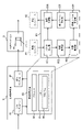
- FIG. 1 is a diagram showing the configuration of a communication system according to an embodiment of the present disclosure
- FIG. 1 is a diagram showing the configuration of a band control device according to an embodiment of the present disclosure
- FIG. 2 is a diagram illustrating functions of a band control device according to an embodiment of the present disclosure
- FIG. 2 is a diagram illustrating functions of a band control device according to an embodiment of the present disclosure
- FIG. 2 is a diagram illustrating functions of a band control device according to an embodiment of the present disclosure
- FIG. 2 is a diagram illustrating functions of a band control device according to an embodiment of the present disclosure
- FIG. 2 is a diagram illustrating functions of a band control device according to an embodiment of the present disclosure
- FIG. 2 is a diagram illustrating functions of a band control device according to an embodiment of the present disclosure
- FIG. 2 is a diagram illustrating functions of a band control device according to an embodiment of the present disclosure
- FIG. 2 is a diagram illustrating functions of a band control device according to an embodiment of the present disclosure
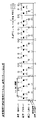
- FIG. 4 is a diagram for explaining effects of the band control device according to the embodiment of the present disclosure
- FIG. 1 is a diagram showing the configuration of a communication system 10 according to an embodiment of the present disclosure.
- the communication system 10 is a system that implements packet communication between the transmitting terminal 4 and the receiving terminal 5 . Communicated packets include audio and video data.
- Communication system 10 includes communication lines 2, 3 over which packets are transmitted.
- the communication system 10 also includes a router 6 connecting the transmitting terminal 4 and the communication line 2 and a router 7 connecting the receiving terminal 5 and the communication line 3 .
- the two communication lines 2 and 3 have different bands.
- the communication line (first band line) 2 on the transmitting side is configured as a broadband line with a relatively wide band
- the communication line (second band line) 3 on the receiving side is configured as a narrow band line with a relatively narrow band. Configured as a bandwidth line.
- the communication system 10 includes a relay gateway 9 that relays the communication lines 2 and 3.
- the relay gateway 9 has a queue-based buffer. Packets input to the relay gateway 9 through the communication line 2 are temporarily stored in a buffer and output to the communication line 3 in order of input. However, if packets exceeding the capacity of the buffer are input due to burst traffic, for example, the packets overflowing the buffer are discarded at the relay gateway 9 .
- the communication system 10 includes a band control device 8.
- the band control device 8 is provided upstream of the communication flow with respect to the relay gateway 9 , that is, on the communication line 2 .
- the bandwidth controller 8 is configured to discard packets according to a certain rule before the packets reach the relay gateway 9 in order to reduce the amount of packets discarded by the relay gateway 9 .
- the rules that the bandwidth controller 8 follows in discarding packets include a discard rate.
- Various conventionally proposed methods for determining the discard rate can be applied to the band control device 8 .
- the bandwidth controller 8 uses a discard rate calculated by the following formula.
- pl is the discard rate
- Bq is the bandwidth of the communication line 2
- Br is the bandwidth of the communication line 3.
- the values of the bands Bq and Br may be notified from any node, or may be set in advance when the communication system 10 is constructed.
- the above formula is the ratio of the difference between the bandwidth Bq on the input side of the relay gateway 9 and the bandwidth Br on the output side of the relay gateway 9 to the bandwidth Bq on the input side of the relay gateway 9. It represents the probability of occurrence of loss.
- the bandwidth control device 8 discards packets according to the packet loss occurrence probability. For example, if the bandwidth Bq of the communication line 2 has a packet rate of 12 packets/second and the bandwidth Br of the communication line 2 has a packet rate of 9 packets/second, the packet discard rate pl by the bandwidth controller 8 is 0.25. becomes.
- the band control device 8 evenly discards packets among all communication flows. That is, packets are discarded at the same packet discard rate pl in all communication flows.
- communication is established between transmitting terminal A and receiving terminal X
- communication is established between transmitting terminal B and receiving terminal Y
- communication is established between transmitting terminal C and receiving terminal Z.
- Communication is established.
- the packet rates of packets transmitted by the transmitting terminals A, B, and C are assumed to be 5/second, 4/second, and 3/second, respectively.
- packets are discarded at a discard rate of 0.25, and the packet rates of the packets received by the receiving terminals X, Y, and Z are reduced to are 15/4, 3/s, and 9/4/s.
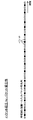
- FIG. 1 shows the time series of input packets to the band control device 8 composed of packets transmitted from transmitting terminals A, B, and C.
- the band control device 8 By uniformly discarding packets for all communication flows in the band control device 8, an output packet time series from the band control device 8 as shown in FIG. 1 is obtained.
- the output packet time series from the band control device 8 becomes the input packet time series to the relay gateway 9 as it is.
- shaping is performed on the input packet time series.
- an output packet time series having a constant packet interval is obtained from the relay gateway 9 .
- the time series of output packets from the band control device 8 will have irregular intervals due to the phase shift between the communication flows. If the packet interval continues to be close, the possibility of packets overflowing from the buffer at the relay gateway 9 increases. Conversely, if the packet interval continues to be sparse, the possibility of packets overflowing from the buffer decreases. Therefore, in order to minimize the packet loss in the relay gateway 9, it is important to optimize the discard pattern.
- the configuration and functions of the band control device 8 for optimizing the discard pattern will be described below.
- FIG. 2 is a diagram showing the configuration of the band control device 8 according to this embodiment.
- FIG. 2 is a block diagram showing an example of the hardware configuration of the band control device 8.
- the band control device 8 can be composed of a reception interface 81 , a transmission interface 82 and an information processing device 83 .
- a packet input to the bandwidth control device 8 is received by the reception interface 81 and processed by the information processing device 83 .
- a packet processed by the information processing device 83 is transmitted from the transmission interface 82 to the relay gateway 9 .
- the information processing device 83 includes a plurality of processors 84 (hereinafter simply referred to as processors 84) and one or more memories 85 (hereinafter simply referred to as memories 85) coupled to the processors 84.
- Memory 85 includes a main memory and an auxiliary memory.
- the memory 85 stores one or more programs 86 executable by the processor 84 (hereinafter simply referred to as programs 86) and various information related thereto.
- the program 86 can be stored in the main storage device or in a computer-readable recording medium that is an auxiliary storage device. Program 86 can also be provided through a network.
- FIG. 2 the functions of a packet assembly unit 831, a communication identification unit 832, a communication management unit 833, a discard cycle calculation unit 834, a discard pattern determination unit 835, and a transmission control unit 836, which constitute the information processing device 83, are implemented by the program 86. It is realized by being executed by the processor 84 .
- the functions of the units 831 to 836 constituting the information processing device 83 will be described below with reference to FIGS. 3 to 9.
- the packet assembly unit 831 is as shown in FIG. Packets from each transmission terminal received by the reception interface 81 are assembled in chronological order. The packet assembly unit 831 sends the assembled input packet time series to the communication identification unit 832 and, in parallel, also sends the input packet time series to the transmission control unit 836 .
- the communication identification unit 832 analyzes the input packet time series received from the packet assembly unit 831, and from the packet source address, source port number, destination address, and destination port number included as control information in the input packet time series, Identify communications.
- the communication management unit 833 manages packets for each communication identified by the communication identification unit 832, as shown in FIG. Communication is performed by a combination of a sending terminal 4 and a receiving terminal 5, more specifically, a combination of a source address and a source port number specifying the sending terminal 4 and a destination address and a destination port number specifying the receiving terminal 5.
- the communication 1 is the communication related to the communication flow from the transmitting terminal A to the receiving terminal X
- the communication 2 is the communication related to the communication flow from the transmitting terminal B to the receiving terminal Y
- the communication flow from the transmitting terminal C to the receiving terminal Z. is communication 3.
- the discard cycle calculator 834 calculates the discard cycle for packets managed by the communication manager 833 for each communication.
- the packet interval Ti is calculated for each communication.
- the packet interval Ti is not the individual packet interval for each packet, but the average packet interval expressed as the reciprocal of the packet rate.
- the packet interval T1 of communication 1 is 1/5 second
- the packet interval T2 of communication 2 is 1/4 second
- the packet interval T3 of communication 3 is 1/3 second.
- the discard cycle calculator 834 calculates the discard interval Tdi from the packet interval Ti for each communication.
- a discard interval means a cycle in which packets are discarded.
- the packet discard rate pl is 0.25, packets are discarded every four packets in each communication. Assuming that the packet interval of each communication is as in the above example, the discard interval of communication 1 is 4/5 seconds, the discard interval of communication 2 is 1 second, and the discard interval of communication 3 is 4/3 seconds.
- the discard pattern for each communication is repeated at the above-mentioned discard interval, but for the entire communication, the discard pattern is repeated for each least common multiple of the discard intervals of each communication. More specifically, the time is the least common multiple of the repetition number (natural number) in each communication of the greatest common divisor of the discard intervals of each communication. In the above example, the greatest common divisor of 4/3, 1, and 4/5 is 1/15 at 4/(3 ⁇ 4 ⁇ 5), so in each communication, 20 times, 15 times, and Twelve times is the "discard interval". The least common multiple of those multiples is 60, so the "discard cycle" sought in the above example would be 60 times 1/15 second, or 4 seconds.
- the discard pattern determining section 835 determines a discard pattern that can minimize packet loss at the relay gateway 9 in the discard cycle calculated by the discard cycle calculating section 834 .
- the discard pattern determining unit 835 assigns a cycle number to a packet managed for each communication by the communication managing unit 833 with a cycle of the discard interval. Specifically, the discard pattern determination unit 835 counts the arrival order of packets arriving at the bandwidth control device 8 for each communication, and assigns an arrival order number to each packet of each communication. Then, the period number of each packet is calculated by the following equation using the arrival order number and the packet loss rate pl.
- the discard pattern determining unit 835 calculates all discard patterns that can be obtained by combining the cycle numbers of the respective discard packets of each communication.
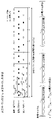
- FIG. 7 illustrates two discard patterns.
- Discard pattern 1 is a pattern in which communication 1 discards packets with period number 3, communication 2 discards packets with period number 0, and communication 3 discards packets with period number 2.
- FIG. Discard pattern 2 is a pattern in which communication 1 discards packets with period number 1, communication 2 discards packets with period number 3, and communication 3 discards packets with period number 3.
- FIG. The number of discard patterns is determined by the packet discard rate pl and the number of communication flows. When the number of communication flows is n, the number of discard patterns can be calculated by the following formula.
- the discard pattern determination unit 835 calculates the time change of the buffer accumulation amount within the discard cycle time in the relay gateway 9 for each discard pattern.
- the temporal change in the buffer accumulation amount of the relay gateway is the bandwidth Bq from the bandwidth controller 8 to the relay gateway 9, the bandwidth Br from the relay gateway 9 to the terminal, and the number of packets of each communication flow input to the bandwidth controller 8. calculated from traffic.
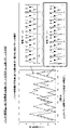
- FIG. 8 exemplifies temporal changes in the buffer accumulated amount within the discard cycle time according to the discard pattern 1 and temporal changes in the buffer accumulated amount within the discard cycle time according to the discard pattern 2 .
- the traffic of packets input to the band control device 8 can be obtained by observation. However, if information on packet traffic is included in the control information of each communication, it can also be referred to.
- the discard pattern determination unit 835 calculates the representative value of the buffer accumulation amount per discard cycle for each discard pattern based on the temporal change in the buffer accumulation amount within the discard cycle time calculated for each discard pattern.
- Suitable representative values can include, for example, average values and maximum values. Alternatively, a median value or a mode value may be used as the representative value. In this embodiment, an average value is used as the representative value.
- the discard pattern determining unit 835 calculates the average buffer accumulation amount per discard cycle for each discard pattern.
- the discard pattern determination unit 835 selects the discard pattern that minimizes the average buffer accumulation amount per discard cycle as the optimum discard pattern.
- the average value of the buffer accumulation amount according to the discard pattern 1 is smaller than the average value of the buffer accumulation amount according to the discard pattern 2 .
- discard pattern determining section 835 selects discard pattern 1 as the optimum discard pattern.
- the discard pattern determination section 835 sends the determined optimum discard pattern to the transmission control section 836 .
- the transmission control unit 836 performs processing for discarding packets according to the optimal discard pattern sent from the discard pattern determination unit 835 for the input packet time series sent from the packet assembly unit 831 . As a result, an output packet time series as shown in FIG. 9 is obtained.
- the transmission control unit 836 transmits packets via the transmission interface 82 according to the output packet time series obtained by the packet discard processing. A packet transmitted from the transmission interface 82 is input to the relay gateway 9 and temporarily stored in the buffer 91 .
- the bandwidth control method according to the embodiment of the present disclosure is executed by the bandwidth control device 8 configured as described above.
- the discard interval is calculated from the packet discard rate and the packet rate for each of a plurality of communications, and the discard cycle, which is the least common multiple of the discard intervals of the plurality of communications, is calculated.
- a step of calculating is performed.
- a step of calculating a representative value of the buffer accumulation amount per discard cycle in the relay gateway 9 is executed based on the traffic. As described above, for example, an average value or maximum value can be used as the representative value.
- a step of selecting the optimum discard pattern that minimizes the representative value of the buffer accumulation amount from among all the discard patterns and discarding packets of a plurality of communications in accordance with the optimum discard pattern is executed.
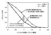
- FIG. 10 is a diagram for explaining the effects of the band control method according to this embodiment.
- FIG. 10 shows simulation results of the packet loss rate for each buffer capacity of the relay gateway 9 with the bandwidth control method according to the present embodiment and the bandwidth control method of the comparative example.
- packets are evenly discarded at regular intervals.
- the bandwidth control method according to the present embodiment it is possible to suppress packet loss in the relay gateway 9 and improve throughput.
Landscapes
- Data Exchanges In Wide-Area Networks (AREA)
Abstract
本開示の帯域制御装置は、広域帯域回線を流れる複数の通信フローのパケットを、通信フロー毎に所定の廃棄率で廃棄しつつ、広帯域回線と狭域帯域回線とを中継する中継ゲートウェイへ転送する装置であって、以下の処理を実行する。第1処理では、複数の通信フローのそれぞれについて廃棄率とパケットレートとから廃棄間隔を計算し、複数の通信フローのそれぞれの廃棄間隔の最小公倍数である廃棄サイクルを計算する。第2処理では、複数の通信フローのそれぞれの廃棄パケットの周期番号を組み合わせてできる全ての廃棄パターンについて、広域帯域回線の帯域と狭域帯域回線の帯域と入力トラヒックとに基づいて、中継ゲートウェイにおける廃棄サイクルあたりのバッファ蓄積量の代表値を算出する。第3処理では、全ての廃棄パターンの中からバッファ蓄積量の代表値が最小になる最適廃棄パターンを選択し、最適廃棄パターンにて複数の通信フローのパケットを廃棄する。
Description
本開示は、帯域制御装置、帯域制御方法、及び帯域制御プログラムに関する。
近年のスマートフォンなど従来よりも大容量通信を行う端末の増加、また、テザリングなどの大容量通信の増加により、帯域の逼迫やバックボーンの負荷増大による通信の混雑や障害が頻発している。回線への負荷軽減と回線の破綻を防止する観点から、多くの通信事業者において帯域制御が行われている。帯域制御に関連する従来技術としては、例えば、以下の非特許文献1及び特許文献1-4を挙げることができる。
非特許文献1には、動画における音声と映像の変化に着目して、変化の少ない冗長なフレームを間引いていくことで動画の内容を保持したまま動画の長さを短くすることが開示されている。特許文献1には、複数のキューにパケットを振り分けるときにREDアルゴリズムを適用するパケット処理方法において、同じフローに属するすべてのパケット群を同じキューに振り分けることが開示されている。特許文献2には、複数のキューに格納される前の一連のパケットから、選択した1またはそれ以上のキュー宛てのパケットを分離し、分離したパケットを所定の確率で廃棄することが開示されている。特許文献3には、音声データが設定再生時間以内で終了するようにデータを一定周期かつ均等に間引くことが開示されている。特許文献4には、通信装置を通過するアクティブフローごとにフローサイズを累計し、フローサイズを用いて計算されるパケットの廃棄確率に従って、アクティブフローのパケットを廃棄することが開示されている。
平井,森島,"音声と映像の変化に注目したフレーム間引きによる動画要約手法"情報処理学会研究報告,Vol.2015-MUS-107 No.18,2015/5/23
上記の各従来技術のように、一定の確率でパケットを廃棄することによってトラヒックを制御することは知られている。しかし、このようなトラヒック制御を行っていたとしても、バーストトラヒックが発生した場合には、広域帯域回線と狭域帯域回線とを中継する中継ゲートウェイにおいて、バッファからパケットが溢れることによるパケットロスが発生する可能性がある。パケットロスの発生は通信システムのスループットを低下させる。
本開示は、上記事情に着目してなされたもので、中継ゲートウェイにおけるパケットロスを抑制してスループットを向上させることができる技術を提供することを目的とする。
本開示は、上記目的を達成するため、帯域制御装置を提供する。本開示の帯域制御装置は、第1帯域回線を流れる複数の通信フローのパケットを、通信フロー毎に所定の廃棄率で廃棄しつつ、第1帯域回線と第1帯域回線よりも帯域が狭い第2帯域回線とを中継する中継ゲートウェイへ転送する装置である。本開示の帯域制御装置は、以下の(1)~(3)の処理を実行するように構成されている。
(1)複数の通信フローのそれぞれについて廃棄率とパケットレートとから廃棄間隔を計算し、複数の通信フローのそれぞれの廃棄間隔の最小公倍数である廃棄サイクルを計算する処理
(2)複数の通信フローのそれぞれの廃棄パケットの周期番号を組み合わせてできる全ての廃棄パターンについて、第1帯域回線の帯域と、第2帯域回線の帯域と、帯域制御装置に入力されるパケットのトラヒックとに基づいて、中継ゲートウェイにおける廃棄サイクルあたりのバッファ蓄積量の代表値を算出する処理
(3)全ての廃棄パターンの中からバッファ蓄積量の代表値が最小になる最適廃棄パターンを選択し、最適廃棄パターンにて複数の通信フローのパケットを廃棄する処理
(1)複数の通信フローのそれぞれについて廃棄率とパケットレートとから廃棄間隔を計算し、複数の通信フローのそれぞれの廃棄間隔の最小公倍数である廃棄サイクルを計算する処理
(2)複数の通信フローのそれぞれの廃棄パケットの周期番号を組み合わせてできる全ての廃棄パターンについて、第1帯域回線の帯域と、第2帯域回線の帯域と、帯域制御装置に入力されるパケットのトラヒックとに基づいて、中継ゲートウェイにおける廃棄サイクルあたりのバッファ蓄積量の代表値を算出する処理
(3)全ての廃棄パターンの中からバッファ蓄積量の代表値が最小になる最適廃棄パターンを選択し、最適廃棄パターンにて複数の通信フローのパケットを廃棄する処理
本開示は、上記目的を達成するため、帯域制御プログラムを提供する。本開示の帯域制御プログラムは、コンピュータに上記の帯域制御装置の機能を実現させるためのプログラムを含む。すなわち、上記の帯域制御装置は、コンピュータと帯域制御プログラムとによって実現することができる。帯域制御プログラムは、コンピュータ読み取り可能な記録媒体に記録されていてもよい。帯域制御プログラムは、ネットワーク経由で提供されてもよい。
また、本開示は、上記目的を達成するため、帯域制御方法を提供する。本開示の帯域制御方法は、第1帯域回線を流れる複数の通信フローのパケットを、通信フロー毎に所定の廃棄率で廃棄しつつ、第1帯域回線と第1帯域回線よりも帯域が狭い第2帯域回線とを中継する中継ゲートウェイへ転送する方法である。本開示の帯域制御方法は、以下の(1)~(3)のステップを含む。
(1)複数の通信フローのそれぞれについて廃棄率とパケットレートとから廃棄間隔を計算し、複数の通信フローのそれぞれの廃棄間隔の最小公倍数である廃棄サイクルを計算するステップ
(2)複数の通信フローのそれぞれの廃棄パケットの周期番号を組み合わせてできる全ての廃棄パターンについて、第1帯域回線の帯域と、第2帯域回線の帯域と、第1帯域回線に入力されるパケットのトラヒックとに基づいて、中継ゲートウェイにおける廃棄サイクルあたりのバッファ蓄積量の代表値を算出するステップ
(3)全ての廃棄パターンの中からバッファ蓄積量の代表値が最小になる最適廃棄パターンを選択し、最適廃棄パターンにて複数の通信フローのパケットを廃棄するステップ
(1)複数の通信フローのそれぞれについて廃棄率とパケットレートとから廃棄間隔を計算し、複数の通信フローのそれぞれの廃棄間隔の最小公倍数である廃棄サイクルを計算するステップ
(2)複数の通信フローのそれぞれの廃棄パケットの周期番号を組み合わせてできる全ての廃棄パターンについて、第1帯域回線の帯域と、第2帯域回線の帯域と、第1帯域回線に入力されるパケットのトラヒックとに基づいて、中継ゲートウェイにおける廃棄サイクルあたりのバッファ蓄積量の代表値を算出するステップ
(3)全ての廃棄パターンの中からバッファ蓄積量の代表値が最小になる最適廃棄パターンを選択し、最適廃棄パターンにて複数の通信フローのパケットを廃棄するステップ
本開示に係る帯域制御装置、帯域制御方法、及び帯域制御プログラムによれば、中継ゲートウェイにおけるパケットロスを抑制してスループットを向上させることができる。
図1は、本開示の実施形態に係る通信システム10の構成を示す図である。通信システム10は、送信端末4と受信端末5との間のパケット通信を実現するシステムである。通信されるパケットには、音声と映像データとが含まれる。通信システム10は、パケットが伝送される通信回線2,3を含む。また、通信システム10は、送信端末4と通信回線2とを接続するルータ6と、受信端末5と通信回線3とを接続するルータ7とを含む。2つの通信回線2,3は帯域が異なる。送信側の通信回線(第1帯域回線)2は帯域が相対的に広い広帯域回線として構成されているのに対し、受信側の通信回線(第2帯域回線)3は帯域が相対的に狭い狭帯域回線として構成されている。
通信システム10は、通信回線2と通信回線3とを中継する中継ゲートウェイ9を含む。中継ゲートウェイ9はキュー方式のバッファを備える。通信回線2を通って中継ゲートウェイ9に入力されたパケットは、バッファに一時的に蓄えられ、入力された順に通信回線3へ出力される。ただし、例えばバーストトラヒックの発生により、バッファの容量を越えるパケットが入力された場合、バッファから溢れたパケットは中継ゲートウェイ9において廃棄される。
通信システム10は、帯域制御装置8を含む。帯域制御装置8は、中継ゲートウェイ9に対して通信フローの上流、すなわち、通信回線2に設けられている。帯域制御装置8は、中継ゲートウェイ9において成り行きにより廃棄されるパケットの量を抑えるため、パケットが中継ゲートウェイ9に到達するよりも前に一定のルールに従ってパケットを廃棄するように構成されている。
帯域制御装置8がパケットの廃棄において従うルールには、廃棄率が含まれる。帯域制御装置8には、従来提案されている様々な廃棄率の決定方法を適用することができる。しかし、本実施形態では、以下の計算式で計算される廃棄率が帯域制御装置8において用いられる。ここで、plは廃棄率、Bqは通信回線2の帯域、Brは通信回線3の帯域である。帯域Bq及びBrの値は、いずれかのノードから通知を受けてもよいし、通信システム10を構築する際にあらかじめ設定しておいてもよい。

上記の計算式は、中継ゲートウェイ9の入力側の帯域Bqと中継ゲートウェイ9の出力側の帯域Brの差分の中継ゲートウェイ9の入力側の帯域Bqに対する比率であり、これは中継ゲートウェイ9でのパケットロスの発生確率を表している。帯域制御装置8は、パケットロスの発生確率に応じてパケットを廃棄する。例えば、通信回線2の帯域Bqがパケットレートで12個/秒、通信回線2の帯域Brがパケットレートで9個/秒であるとすると、帯域制御装置8によるパケットの廃棄率plは0.25となる。
また、帯域制御装置8は、全ての通信フロー間で均等にパケットを廃棄する。つまり、全ての通信フローにおいて同一のパケット廃棄率plはでパケットが廃棄される。図1に示す例では、送信端末Aと受信端末Xとの間で通信が確立され、送信端末Bと受信端末Yとの間で通信が確立され、送信端末Cと受信端末Zとの間で通信が確立されている。ここで、送信端末A、B、Cが送信するパケットのそれぞれのパケットレートを5個/秒、4個/秒、3個/秒とする。帯域Br及び帯域Brの各幅が上述の例のとおりであるとすると、0.25の廃棄率でパケットが廃棄されることで、受信端末X、Y、Zが受信するパケットのそれぞれのパケットレートは15/4個/秒、3個/秒、及び9/4個/秒となる。
図1には、送信端末A、B、Cから送信されたパケットで構成される帯域制御装置8への入力パケット時系列が示されている。帯域制御装置8において全ての通信フローに対して均等にパケットが廃棄されることで、図1中に示すような帯域制御装置8からの出力パケット時系列が得られる。帯域制御装置8からの出力パケット時系列は、そのまま中継ゲートウェイ9への入力パケット時系列となる。中継ゲートウェイ9では、入力パケット時系列に対してシェーピングが行われる。これにより、中継ゲートウェイ9からはパケット間隔を一定にされた出力パケット時系列が得られる。
以上の処理によって、中継ゲートウェイ9においてバッファから溢れるパケットは低減される。しかし、中継ゲートウェイ9におけるパケットロスを最小限まで抑えるためには更なる工夫の余地がある。その工夫が帯域制御装置8において各通信フローからパケットを抜き取り廃棄する際の廃棄パターンである。
パケットレートが異なる通信フロー毎に一定の間隔でパケットを廃棄する場合、通信フロー間の位相のずれによって帯域制御装置8からの出力パケット時系列にはパケット間隔の疎密が生じる。パケット間隔が密の状態が続く場合、中継ゲートウェイ9においてバッファからパケットが溢れる可能性が高まる。逆に、パケット間隔が疎の状態が続く場合、バッファからパケットが溢れる可能性は低下する。ゆえに、中継ゲートウェイ9におけるパケットロスを最小限まで抑える上では、廃棄パターンを適正化することが重要である。以下では、廃棄パターンを適正化するための帯域制御装置8の構成と、その機能について説明する。
図2は、本実施形態に係る帯域制御装置8の構成を示す図である。図2には、帯域制御装置8のハードウェア構成の一例がブロック図で示されている。帯域制御装置8は、受信インタフェース81、送信インタフェース82、及び情報処理装置83で構成することができる。帯域制御装置8に入力されるパケットは受信インタフェース81で受信され、受信されたパケットは情報処理装置83で処理される。情報処理装置83で処理されたパケットは送信インタフェース82から中継ゲートウェイ9へ送信される。
情報処理装置83は、複数のプロセッサ84(以下、単にプロセッサ84と呼ぶ)と、プロセッサ84に結合された1又は複数のメモリ85(以下、単にメモリ85と呼ぶ)とを含んでいる。メモリ85は主記憶装置と補助記憶装置とを含む。メモリ85には、プロセッサ84で実行可能な1又は複数のプログラム86(以下、単にプログラム86と呼ぶ)とそれに関連する種々の情報とが記憶されている。プログラム86は、主記憶装置に記憶されることもできるし、補助記憶装置であるコンピュータ読み取り可能な記録媒体に記憶されることもできる。また、プログラム86は、ネットワーク通して提供することも可能である。
プロセッサ84がプログラム86を実行することにより、プロセッサ84による各種処理が実現される。図2において情報処理装置83を構成するパケット組立部831、通信識別部832、通信管理部833、廃棄サイクル計算部834、廃棄パターン決定部835、及び送信制御部836の各機能は、プログラム86がプロセッサ84により実行されることで実現される。以下、情報処理装置83を構成する各部831-836の機能について図3乃至9を用いて説明する。
パケット組立部831は、図3に示すように。受信インタフェース81で受信した各送信端末からのパケットを時系列に組み立てる。パケット組立部831は、組み立てた入力パケット時系列を通信識別部832に送り、並行して、送信制御部836にも入力パケット時系列を送る。
通信識別部832は、パケット組立部831から受け取った入力パケット時系列を解析し、入力パケット時系列に制御情報として含まれるパケットの送信元アドレス、送信元ポート番号、宛先アドレス、及び宛先ポート番号から通信を識別する。
通信管理部833は、図4に示すように、通信識別部832で識別された通信毎にパケットを管理する。通信は、送信端末4と受信端末5との組み合わせ、より詳しくは、送信端末4を特定する送信元アドレス及び送信元ポート番号と、受信端末5を特定する宛先アドレス及び宛先ポート番号との組み合わせによって定義される。ここでは、送信端末Aから受信端末Xへの通信フローに係る通信を通信1、送信端末Bから受信端末Yへの通信フローに係る通信を通信2、送信端末Cから受信端末Zへの通信フローに係る通信を通信3とする。
廃棄サイクル計算部834は、図5に示すように、通信管理部833によって通信毎に管理されるパケットに対して廃棄サイクルの計算を行う。廃棄サイクルの計算では、まず、通信毎にパケット間隔Tiが計算される。パケット間隔Tiは、パケット毎の個別のパケット間隔ではなく、パケットレートの逆数で表される平均パケット間隔である。図5に示す例では、通信1のパケット間隔T1は1/5秒、通信2のパケット間隔T2は1/4秒、通信3のパケット間隔T3は1/3秒である。
次に、廃棄サイクル計算部834は、通信毎にパケット間隔Tiから廃棄間隔Tdiを計算する。廃棄間隔とは、パケットが廃棄される周期を意味する。パケット廃棄率plが0.25の場合、それぞれの通信では4パケットごとにパケットの廃棄が行われる。各通信のパケット間隔が上記例のとおりであるとすると、通信1の廃棄間隔は4/5秒、通信2の廃棄間隔は1秒、通信3の廃棄間隔は4/3秒である。
通信毎の廃棄パターンは上述の廃棄間隔で繰り返されるが、通信全体では、各通信の廃棄間隔の最小公倍数ごとに廃棄パターンが繰り返される。より詳しくは、各通信の廃棄間隔の最大公約数の各通信での繰り返し数(自然数)の最小公倍数分の時間となる。上記の例では、4/3、1、4/5の最大公約数は4/(3×4×5)で1/15なるので、各通信においては最大公約数の20倍、15倍、および12倍が「廃棄間隔」となる。それらの倍数の最小公倍数は60であるので、上記の例での求める「廃棄サイクル」は1/15秒の60倍、すなわち、4秒となる。
廃棄パターン決定部835は、廃棄サイクル計算部834で計算された廃棄サイクルにおける中継ゲートウェイ9でのパケットロスを最小限まで抑えることができる廃棄パターンを決定する。廃棄パターン決定部835は、まず、図6に示すように、通信管理部833によって通信毎に管理されるパケットに対して廃棄間隔の周期で周期番号を付与する。具体的には、廃棄パターン決定部835は、パケットが帯域制御装置8に到着した到着順を通信毎に数え、各通信の各パケットに到着順番号を付与する。そして、到着順番号とパケット廃棄率plとを用いて以下の式により各パケットの周期番号を計算する。

次に、廃棄パターン決定部835は、各通信のそれぞれの廃棄パケットの周期番号を組み合わせてできる全ての廃棄パターンを計算する。図7には、2つの廃棄パターンが例示されている。廃棄パターン1は、通信1は周期番号3のパケットを廃棄し、通信2は周期番号0のパケットを廃棄し、通信3は周期番号2のパケットを廃棄するパターンである。廃棄パターン2は、通信1は周期番号1のパケットを廃棄し、通信2は周期番号3のパケットを廃棄し、通信3は周期番号3のパケットを廃棄するパターンである。廃棄パターンの数は、パケットの廃棄率plと通信フローの数とによって決まる。通信フローの数がnの場合、廃棄パターン数は、以下の式で計算することができる。

次に、廃棄パターン決定部835は、中継ゲートウェイ9における廃棄サイクル時間内のバッファ蓄積量の時間変化を廃棄パターン毎に計算する。中継ゲートウェイのバッファ蓄積量の時間変化は、帯域制御装置8から中継ゲートウェイ9までの帯域Bqと、中継ゲートウェイ9から端末までの帯域Brと、帯域制御装置8に入力される各通信フローのパケットのトラヒックとから算出される。図8には、廃棄パターン1による廃棄サイクル時間内のバッファ蓄積量の時間変化と、廃棄パターン2による廃棄サイクル時間内のバッファ蓄積量の時間変化とが例示されている。なお、帯域制御装置8に入力されるパケットのトラヒックについては、観測によって取得することができる。ただし、各通信の制御情報にパケットのトラヒックに関する情報が含まれている場合、それを参照することもできる。
次に、廃棄パターン決定部835は、廃棄パターン毎に計算した廃棄サイクル時間内のバッファ蓄積量の時間変化に基づき、廃棄サイクルあたりのバッファ蓄積量の代表値を廃棄パターン毎に計算する。好適な代表値としては、例えば、平均値、及び最大値を挙げることができる。また、代表値として中央値や最頻値を用いても良い。本実施形態では、代表値として平均値が用いられている。廃棄パターン決定部835は、廃棄サイクルあたりのバッファ蓄積量の平均値を廃棄パターン毎に計算する。
廃棄パターン決定部835は、廃棄サイクルあたりのバッファ蓄積量の平均値が最小となる廃棄パターンを最適廃棄パターンとして選択する。図8に示す例では、廃棄パターン2によるバッファ蓄積量の平均値よりも廃棄パターン1によるバッファ蓄積量の平均値のほうが小さい。廃棄パターン1によるバッファ蓄積量の平均値が全ての廃棄パターンの中で最小の場合、廃棄パターン決定部835は、廃棄パターン1を最適廃棄パターンとして選択する。廃棄パターン決定部835は、決定した最適廃棄パターンを送信制御部836に送る。
送信制御部836は、パケット組立部831から送られた入力パケット時系列に対し、廃棄パターン決定部835から送られた最適廃棄パターンに従ってパケットを廃棄する処理を行う。これにより、図9に示すような出力パケット時系列が得られる。送信制御部836は、パケットの廃棄処理によって得られた出力パケット時系列に従い、送信インタフェース82を介してパケットを送信する。送信インタフェース82から送信されたパケットは、中継ゲートウェイ9に入力されてバッファ91に一時的に蓄えられる。
以上のように構成された帯域制御装置8によって、本開示の実施形態に係る帯域制御方法が実行される。本実施形態に係る帯域制御方法によれば、まず、複数の通信のそれぞれについてパケット廃棄率とパケットレートとから廃棄間隔を計算し、複数の通信のそれぞれの廃棄間隔の最小公倍数である廃棄サイクルを計算するステップが実行される。
次に、複数の通信のそれぞれの廃棄パケットの周期番号を組み合わせてできる全ての廃棄パターンについて、通信回線2の帯域Bqと、通信回線3の帯域Brと、帯域制御装置8に入力されるパケットのトラヒックとに基づいて、中継ゲートウェイ9における廃棄サイクルあたりのバッファ蓄積量の代表値を算出するステップが実行される。前述のとおり、代表値としては例えば平均値や最大値を用いることができる。
そして、全ての廃棄パターンの中からバッファ蓄積量の代表値が最小になる最適廃棄パターンを選択し、最適廃棄パターンにて複数の通信のパケットを廃棄するステップが実行される。以上のステップが実行されることにより、中継ゲートウェイ9においてバッファ91からパケットが溢れることによるパケットロスの発生は抑制される。
図10は、本実施形態に係る帯域制御方法の効果を説明する図である。図10には、本実施形態に係る帯域制御方法と比較例の帯域制御方法とで、中継ゲートウェイ9のバッファ容量ごとのパケットロス率をそれぞれシミュレーションしたシミュレーション結果が示されている。比較例では、本実施形態のように廃棄サイクル毎に最適な廃棄パターンが選択されるのではなく、一定の周期で均等にパケットが廃棄されている。このシミュレーション結果からも明らかなように、本実施形態に係る帯域制御方法によれば、中継ゲートウェイ9におけるパケットロスを抑制してスループットを向上させることができる。
上記実施形態は、本開示の要旨を逸脱しない範囲で種々に変形して実施することができる。すなわち、上記実施形態において各要素の個数、数量、量、範囲などの数に言及されている場合、特に明示した場合や原理的に明らかにその数に特定される場合を除いて、その言及した数に、本開示に係る技術が限定されるものではない。また、上記実施形態において説明する構造等は、特に明示した場合や明らかに原理的にそれに特定される場合を除いて、本開示に係る技術に必ずしも必須のものではない。
2 通信回線(第1帯域回線)
3 通信回線(第2帯域回線)
4 送信端末
5 受信端末
6,7 ルータ
8 帯域制御装置
9 中継ゲートウェイ
10 通信システム
3 通信回線(第2帯域回線)
4 送信端末
5 受信端末
6,7 ルータ
8 帯域制御装置
9 中継ゲートウェイ
10 通信システム
Claims (5)
- 第1帯域回線を流れる複数の通信フローのパケットを、通信フロー毎に所定の廃棄率で廃棄しつつ、前記第1帯域回線と前記第1帯域回線よりも帯域が狭い第2帯域回線とを中継する中継ゲートウェイへ転送する帯域制御装置であって、
前記複数の通信フローのそれぞれについて前記廃棄率とパケットレートとから廃棄間隔を計算し、前記複数の通信フローのそれぞれの廃棄間隔の最小公倍数である廃棄サイクルを計算する処理と、
前記複数の通信フローのそれぞれの廃棄パケットの周期番号を組み合わせてできる全ての廃棄パターンについて、前記第1帯域回線の帯域と、前記第2帯域回線の帯域と、前記帯域制御装置に入力されるパケットのトラヒックとに基づいて、前記中継ゲートウェイにおける前記廃棄サイクルあたりのバッファ蓄積量の代表値を算出する処理と、
前記全ての廃棄パターンの中から前記バッファ蓄積量の前記代表値が最小になる最適廃棄パターンを選択し、前記最適廃棄パターンにて前記複数の通信フローのパケットを廃棄する処理と、を実行するように構成された
ことを特徴とする帯域制御装置。 - 請求項1に記載の帯域制御装置において、
前記第1帯域回線の帯域と前記第2帯域回線の帯域との差分の前記第1帯域回線の帯域に対する比率を前記廃棄率として計算する処理、をさらに実行するように構成された
ことを特徴とする帯域制御装置。 - 請求項1又は2に記載の帯域制御装置において、
前記代表値は平均値又は最大値である
ことを特徴とする帯域制御装置。 - コンピュータに、請求項1乃至3の何れか1項に記載の帯域制御装置の機能を実現させるためのプログラムを含む
ことを特徴とする帯域制御プログラム。 - 第1帯域回線を流れる複数の通信フローのパケットを、通信フロー毎に所定の廃棄率で廃棄しつつ、前記第1帯域回線と前記第1帯域回線よりも帯域が狭い第2帯域回線とを中継する中継ゲートウェイへ転送する帯域制御方法であって、
前記複数の通信のそれぞれについて前記廃棄率とパケットレートとから廃棄間隔を計算し、前記複数の通信のそれぞれの廃棄間隔の最小公倍数である廃棄サイクルを計算するステップと、
前記複数の通信のそれぞれの廃棄パケットの周期番号を組み合わせてできる全ての廃棄パターンについて、前記第1帯域回線の帯域と、前記第2帯域回線の帯域と、前記第1帯域回線に入力されるパケットのトラヒックとに基づいて、前記中継ゲートウェイにおける前記廃棄サイクルあたりのバッファ蓄積量の代表値を算出するステップと、
前記全ての廃棄パターンの中から前記バッファ蓄積量の前記代表値が最小になる最適廃棄パターンを選択し、前記最適廃棄パターンにて前記複数の通信のパケットを廃棄するステップと、を含む
ことを特徴とする帯域制御方法。
Priority Applications (2)
| Application Number | Priority Date | Filing Date | Title |
|---|---|---|---|
| JP2023525223A JP7613577B2 (ja) | 2021-06-01 | 2021-06-01 | 帯域制御装置、帯域制御方法、及び帯域制御プログラム |
| PCT/JP2021/020915 WO2022254591A1 (ja) | 2021-06-01 | 2021-06-01 | 帯域制御装置、帯域制御方法、及び帯域制御プログラム |
Applications Claiming Priority (1)
| Application Number | Priority Date | Filing Date | Title |
|---|---|---|---|
| PCT/JP2021/020915 WO2022254591A1 (ja) | 2021-06-01 | 2021-06-01 | 帯域制御装置、帯域制御方法、及び帯域制御プログラム |
Publications (1)
| Publication Number | Publication Date |
|---|---|
| WO2022254591A1 true WO2022254591A1 (ja) | 2022-12-08 |
Family
ID=84322860
Family Applications (1)
| Application Number | Title | Priority Date | Filing Date |
|---|---|---|---|
| PCT/JP2021/020915 Ceased WO2022254591A1 (ja) | 2021-06-01 | 2021-06-01 | 帯域制御装置、帯域制御方法、及び帯域制御プログラム |
Country Status (2)
| Country | Link |
|---|---|
| JP (1) | JP7613577B2 (ja) |
| WO (1) | WO2022254591A1 (ja) |
Citations (2)
| Publication number | Priority date | Publication date | Assignee | Title |
|---|---|---|---|---|
| JP2009182546A (ja) * | 2008-01-30 | 2009-08-13 | Alaxala Networks Corp | トラフィックシェーピング機能および装置 |
| JP2009246630A (ja) * | 2008-03-31 | 2009-10-22 | Mitsubishi Electric Corp | ホームゲートウェイ装置およびホームゲートウェイ装置の通信品質制御方法 |
Family Cites Families (1)
| Publication number | Priority date | Publication date | Assignee | Title |
|---|---|---|---|---|
| JP4537937B2 (ja) | 2005-11-02 | 2010-09-08 | 日本電信電話株式会社 | 輻輳制御方法、輻輳制御プログラム、および、輻輳制御システム |
-
2021
- 2021-06-01 JP JP2023525223A patent/JP7613577B2/ja active Active
- 2021-06-01 WO PCT/JP2021/020915 patent/WO2022254591A1/ja not_active Ceased
Patent Citations (2)
| Publication number | Priority date | Publication date | Assignee | Title |
|---|---|---|---|---|
| JP2009182546A (ja) * | 2008-01-30 | 2009-08-13 | Alaxala Networks Corp | トラフィックシェーピング機能および装置 |
| JP2009246630A (ja) * | 2008-03-31 | 2009-10-22 | Mitsubishi Electric Corp | ホームゲートウェイ装置およびホームゲートウェイ装置の通信品質制御方法 |
Also Published As
| Publication number | Publication date |
|---|---|
| JP7613577B2 (ja) | 2025-01-15 |
| JPWO2022254591A1 (ja) | 2022-12-08 |
Similar Documents
| Publication | Publication Date | Title |
|---|---|---|
| US7675857B1 (en) | Method and apparatus to avoid network congestion | |
| CN101547159B (zh) | 一种避免网络拥塞的方法和设备 | |
| CN113573419B (zh) | 一种考虑多优先级业务的多跳网络信道接入方法 | |
| CN110739991B (zh) | 一种基于QoS的卫星网络端-端通信可靠性分析方法 | |
| EP1668847B1 (en) | Encapsulating packets into a frame for a network | |
| CN113141313A (zh) | 拥塞控制方法、装置及系统、存储介质 | |
| CN103929372A (zh) | 主动队列管理方法和设备 | |
| CN103916329A (zh) | 一种命名数据网络传输控制方法及系统 | |
| CN111431812B (zh) | 一种报文转发控制方法及装置 | |
| US9654399B2 (en) | Methods and devices in an IP network for congestion control | |
| CN103888372B (zh) | 一种流量整形方法和数据处理设备 | |
| US8660001B2 (en) | Method and apparatus for providing per-subscriber-aware-flow QoS | |
| JPH08504546A (ja) | フレーム中継ネットワーク内の渋滞管理方法及びフレーム中継ネットワークのノード | |
| TWI757887B (zh) | 用以促進一資料流從一發送端透過多路徑傳輸至一接收端的方法、網路控制器以及電腦程式產品 | |
| JP7613577B2 (ja) | 帯域制御装置、帯域制御方法、及び帯域制御プログラム | |
| EP3437267B1 (en) | Methods and apparatus for transmitting data | |
| US20150055471A1 (en) | System and method for quality-based optimization of network traffic | |
| CN101119492A (zh) | 一种基于抖动约束的数据缓存整形方法 | |
| CN108833291B (zh) | 一种应用在交换电路中的加权随机早期检测方法 | |
| CN114884884A (zh) | 一种拥塞控制方法及装置 | |
| CN109257302B (zh) | 一种基于分组排队时间的包散射方法 | |
| CN119865461B (zh) | 一种基于自适应调整的负载均衡方法及相关设备 | |
| CN119966899B (zh) | 一种适合BCube拓扑的逐端口流控方法、介质及设备 | |
| CN120075141B (zh) | 基于线性规划的数据中心流量控制方法、系统及存储介质 | |
| Yang et al. | Research on delay and packet loss control mechanism in wireless mesh networks |
Legal Events
| Date | Code | Title | Description |
|---|---|---|---|
| WWE | Wipo information: entry into national phase |
Ref document number: 2023525223 Country of ref document: JP |
|
| NENP | Non-entry into the national phase |
Ref country code: DE |
|
| 122 | Ep: pct application non-entry in european phase |
Ref document number: 21944095 Country of ref document: EP Kind code of ref document: A1 |