WO2022249684A1 - 不活化システム及び不活化方法 - Google Patents
不活化システム及び不活化方法 Download PDFInfo
- Publication number
- WO2022249684A1 WO2022249684A1 PCT/JP2022/013128 JP2022013128W WO2022249684A1 WO 2022249684 A1 WO2022249684 A1 WO 2022249684A1 JP 2022013128 W JP2022013128 W JP 2022013128W WO 2022249684 A1 WO2022249684 A1 WO 2022249684A1
- Authority
- WO
- WIPO (PCT)
- Prior art keywords
- airflow
- ultraviolet light
- space
- inactivation
- blower
- Prior art date
- Legal status (The legal status is an assumption and is not a legal conclusion. Google has not performed a legal analysis and makes no representation as to the accuracy of the status listed.)
- Ceased
Links
Images

Classifications
-
- A—HUMAN NECESSITIES
- A61—MEDICAL OR VETERINARY SCIENCE; HYGIENE
- A61L—METHODS OR APPARATUS FOR STERILISING MATERIALS OR OBJECTS IN GENERAL; DISINFECTION, STERILISATION OR DEODORISATION OF AIR; CHEMICAL ASPECTS OF BANDAGES, DRESSINGS, ABSORBENT PADS OR SURGICAL ARTICLES; MATERIALS FOR BANDAGES, DRESSINGS, ABSORBENT PADS OR SURGICAL ARTICLES
- A61L9/00—Disinfection, sterilisation or deodorisation of air
- A61L9/16—Disinfection, sterilisation or deodorisation of air using physical phenomena
- A61L9/18—Radiation
- A61L9/20—Ultraviolet radiation
-
- F—MECHANICAL ENGINEERING; LIGHTING; HEATING; WEAPONS; BLASTING
- F24—HEATING; RANGES; VENTILATING
- F24F—AIR-CONDITIONING; AIR-HUMIDIFICATION; VENTILATION; USE OF AIR CURRENTS FOR SCREENING
- F24F9/00—Use of air currents for screening, e.g. air curtains
Definitions
- This invention relates to an inactivation system and an inactivation method.
- shields such as transparent plates and transparent sheets (hereinafter simply referred to as “shields”) have been introduced between people. It can be seen that the space is divided and infection is prevented by arranging
- Patent Literature 1 describes moving bacteria floating in a room to an upper space in the room and sterilizing the upper space by irradiating the upper space with ultraviolet light.
- aerosols While droplets are relatively heavy and fall due to gravity, aerosols are smaller and lighter than droplets, so they can float in the air with a slight air flow even in a gravity environment. And an aerosol can contain bacteria or viruses as well as droplets.
- the ultraviolet light sterilization device of Patent Document 1 does not shield between people. Then, in the ultraviolet light sterilization device of Patent Document 1, there is a risk that another person may inhale the bacteria discharged from a certain person before the bacteria move to the upper space where the ultraviolet light is irradiated, and there is a risk of infection. .
- the problem to be solved by the present invention is to provide a system and method for reducing the risk of bacterial or viral infection.
- the system of the present invention includes an air blower that forms an airflow for partitioning a space where people can stay, an ultraviolet light irradiation device that irradiates the airflow with ultraviolet light that inactivates bacteria or viruses;
- An inactivation system comprising:
- a space where people can be present refers to a space that multiple people can enter, regardless of whether there are actually people or not.
- Specific examples of "a space that multiple people can enter” include spaces in buildings such as restaurants, cafeterias, retail stores, schools, hospitals, theaters, sports gyms, residences or offices, or, for example, automobiles, Including the space inside a vehicle such as a bus, train or airplane.
- Airflow for partitioning a space with surfaces means a planar airflow, that is, an airflow surface is formed in a certain space, and the airflow surface divides the certain space into a first small space and a second small space. Represents separation into space. Separation into two small spaces restricts the mixing of the atmospheres contained in each of the two small spaces over the airflow surface. Two or more airflow planes may be formed in a certain space to divide it into three or more small spaces.
- Bacteria includes all protist organisms that have a cellular structure, such as prokaryotic bacteria and eukaryotic fungi such as molds.
- activation refers to either killing by destroying intracellular DNA or enzymes (proteins) or cell membranes, or removing the cell's proliferation function.
- viruses are something that has a DNA or RNA nucleic acid as a genome that does not have a cellular structure.
- inactivation refers to the loss of the ability to infect cells by destroying their DNA or RNA.
- Pathogens may be contained in droplets or aerosols that are exhaled, saliva, coughed or sneezed from the mouth or nose of a person or animal.
- the inactivation system even if a person in the first small space discharges droplets or aerosols containing pathogens from the mouth or nose, the droplets or aerosols are blocked by the airflow surface and go to the second small space. less likely to scatter. Furthermore, since there is no shielding object such as a conventional transparent plate or transparent sheet, droplets do not adhere to the shielding object, and in addition, the person near the shielding does not feel blocked.
- the formed airflow is irradiated with ultraviolet light that inactivates bacteria or viruses.
- ultraviolet light that inactivates bacteria or viruses.
- droplets or aerosols containing pathogens emitted by a person in the first small space ride on the air current, and even if a person in the second small space inhales the air current, the pathogen is already inactivated. Therefore, the risk of infection is low.
- the wavelength band of ultraviolet light that inactivates bacteria or viruses is, for example, 190-280 nm.
- Reducing the risk of infection corresponds to Goal 3 of the United Nations Sustainable Development Goals (SDGs), "Ensure healthy lives and promote well-being for all at all ages”, and It will contribute significantly to target 3.3 “By 2030, end the epidemics of AIDS, tuberculosis, malaria and neglected tropical diseases, and combat hepatitis, water-borne diseases and other communicable diseases”. .
- SDGs Sustainable Development Goals
- the ultraviolet light is light that has a spectrum substantially in the wavelength band of 190 to 240 nm and substantially does not have a spectrum in the wavelength band of 250 to 280 nm,
- the ultraviolet light may be applied to the airflow at a low position accessible to the person. This improves the safety to the human body and increases the degree of freedom in designing the inactivation system.
- a wavelength band having a substantially spectrum refers to a wavelength band including a peak wavelength of an emission spectrum and a wavelength exhibiting a light intensity of 30% or more with respect to the light intensity at the peak wavelength.
- a wavelength band that has substantially no spectrum in a wavelength band refers to a wavelength band that is suppressed to less than 5% of the light intensity at the peak wavelength.
- the ultraviolet light may be applied to the airflow surface that partitions the space with the airflow.
- pathogens can be inactivated by irradiating with ultraviolet light while the distance they travel on the air current is short.
- the airflow surface that divides the space is separated into a first small space and a second small space, and droplets or aerosols are separated into one small space. Prevents scattering from one space to another small space.
- the airflow surface that divides the space is irradiated with ultraviolet light, for example, droplets or aerosols containing pathogens discharged by a person in the first small space convect in the first small space due to the airflow.
- inactivation of pathogens can be performed by irradiation with ultraviolet light.
- the ultraviolet light may be applied to the airflow above the space that is difficult for people to touch. As a result, the safety for the human body is improved, and the settable range of the ultraviolet light irradiation amount (irradiation intensity and irradiation time) is expanded.
- the upper part of a space that is difficult for people to touch is a space that many people cannot reach even if they reach out with their hands.
- the blower may form an airflow from top to bottom.
- a suction device that sucks the airflow may be provided. This makes it easier to partition the space by suppressing turbulence of the airflow surface.
- an airflow may be formed in the entire at least one small space. This further reduces the risk of infection from a small space with airflow formed throughout.
- the inactivation method of the present invention forms an airflow that divides a space in which people can stay, and irradiates the airflow with ultraviolet light that inactivates bacteria or viruses.
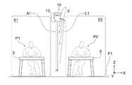
- FIG. 1 is a conceptual diagram showing how an inactivation system 10 is used in a restaurant.
- At least two seats are arranged next to each other in the X direction in the restaurant.
- the seat where the customer P1 is located and the seat where the customer P2 is located are shown.
- Each seat includes a table 5 and a chair (not shown).
- An inactivation system 10 is arranged above (+Z direction) between the seat where the customer P1 is located and the seat where the customer P2 is located.
- the inactivation system 10 includes a blower 1 and an ultraviolet light irradiation device 2 .
- the blower 1 forms an airflow downward (-Z direction).
- the airflow is indicated by solid arrows, one of which is labeled A1.
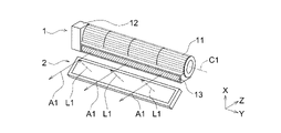
- FIG. 2 shows a specific example of the air blower 1 and the ultraviolet light irradiation device 2.
- the blower device 1 includes blades 11 that rotate around an axis C1, a drive unit 12 that rotates the blades 11, and a blower port 13.
- the blower port 13 has a shape extending in one direction (the Y direction in this embodiment). Therefore, the airflow generated by the blower 1 forms an airflow surface.
- the specific example of this air blower 1 is an example, and is not limited to this.
- the blower mechanism, the size of the blower 1, or the shape of the blower port 13 may be different. For example, a plurality of small air blowers may be arranged in a row to form an airflow surface as a whole.
- the operation of the blower 1 capable of forming an airflow surface will be described with reference to FIG.
- an airflow surface along the YZ plane is formed downward from the air blower port 13 .
- This airflow surface is also commonly referred to as an "air curtain".
- the airflow surface divides one large space into a small space S1 in which the customer P1 resides and a small space S2 in which the customer P2 resides.
- the aerosol is blocked by the airflow surface composed of the airflow A1 and is prevented from scattering into the small space S2 where the customer P2 is present.
- the airflow surface is not limited to a flat surface, and may include a curved surface.
- the thickness of the airflow surface is, for example, 50 mm or more, preferably 100 mm or more, and more preferably 300 mm or more. This makes it easier for the airflow to block droplets or aerosols trying to move across both spaces (S1, S2).
- the flow velocity of the airflow A1 is, for example, 0.1 m/s or more, preferably 0.3 m/s or more. Thereby, a stable airflow surface can be formed.
- the upper limit of the airflow velocity is not particularly limited in terms of the formation of the airflow surface, but considering other factors (for example, the dust caused by the strong airflow and the noise of the blower 1), it is, for example, 8 m/s or less. It is preferable that it is 5.5 m/s or less.
- the ultraviolet light irradiation device 2 irradiates the ultraviolet light L1 that inactivates the pathogens toward the airflow A1 that separates the small spaces S1 and S2.
- the ultraviolet light irradiation device 2 is installed so that the traveling direction of the ultraviolet light L1 intersects with the traveling direction of the airflow A1.
- the light beams emitted from the ultraviolet light irradiation device 2 are indicated by dashed arrows, and one of the arrows is labeled L1.
- airflow A1 is directed to floor F1.
- the air forming the airflow A1 may return to the blower device 1 and be sent out as an airflow from the blower device 1 again.
- the pathogen-containing aerosol discharged from the customer P1 or the customer P2 is put on the airflow A1
- the pathogen will also convect in the space, which will not lead to a reduction in infection risk.
- the ultraviolet light L1 inactivates pathogens contained in the airflow A1, there is no problem even if the aerosol convects in the space.
- the ultraviolet light irradiation device 2 irradiates the airflow with light in the wavelength band of 190 to 280 nm. This inactivates pathogens contained in the airstream.
- the present embodiment uses ultraviolet light that has a spectrum substantially in the wavelength band of 190-240 nm and does not substantially have a spectrum in the wavelength band of 250-280 nm. Light in the wavelength band of 250 to 280 nm may have an adverse effect on the human body, whereas light in the wavelength band of 190 to 240 nm has no risk of affecting the human body and is extremely low in toxicity. Light.
- the ultraviolet light irradiation device can be placed in a position where people can easily touch the light emitted from the ultraviolet light irradiation device, which increases the degree of freedom in designing the inactivation system. improves.
- having a spectrum substantially in the wavelength band of 190 to 240 nm means having a spectrum in at least a part of the wavelength band belonging to the numerical range of 190 to 240 nm. , 190-240 nm. The same applies to other numerical ranges related to wavelength bands.
- a KrCl excimer lamp is used in which a luminous gas containing KrCl is sealed inside the arc tube, and emits ultraviolet light with a main peak wavelength of 222 nm or thereabouts.
- the excimer lamp is not limited to the KrCl excimer lamp.
- a KrBr excimer lamp in which a light emission gas containing KrBr is sealed inside the arc tube, or an ArF excimer lamp in which a light emission gas containing ArF is sealed in the inside of the arc tube may be used.
- a KrBr excimer lamp emits ultraviolet light with a main peak wavelength of 207 nm or thereabouts.
- a solid-state light source may be used instead of the excimer lamp.
- the ultraviolet light emitted from the light source unit preferably has a wavelength range of 190 nm or more and 237 nm or less, more preferably 190 nm or more and 235 nm or less. Even more preferably, it is particularly preferably in the range of 190 nm or more and 230 nm or less.
- the arrangement height of the air blower 1 and the ultraviolet light irradiation device 2 can be set according to the height of the space to be partitioned. In a place such as a restaurant where customers spend a lot of time sitting on chairs as shown in FIG. good.
- the air blower 1 and the ultraviolet light irradiation device 2 may be supported by supports (not shown) extending from the floor F1, or may be suspended from the ceiling (not shown).
- FIG. 1 shows that customers are present in the small spaces S1 and S2, respectively. It may be in a state where it is not present. A space with seats where customers can stay regardless of whether or not there are actually customers is defined as a "space where people can stay.”
- FIG. 1 an example of using the inactivation system in a restaurant has been described, but it is not limited to this, and can be applied to spaces other than restaurants as long as it is a space where multiple people can enter.
- a "seat” does not necessarily consist of a desk and a chair. For example, assuming a buffet-style restaurant, a chair is not essential, and assuming a vehicle or an airplane, it is understood that a desk is not essential.
- each small space (S1, S2) has one customer, but there may be multiple people in each small space (S1, S2).
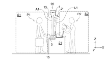
- Fig. 3 is a conceptual diagram showing how the inactivation system 20 is used at a checkout counter where merchandise is checked out at a retail store.
- a shopper P1 and a store clerk P2 face each other across a checkout counter 21, and the store clerk P2 reads the bar code of the product for checkout.
- the deactivation system includes an air blower 1 and an ultraviolet light irradiation device 2 arranged above the checkout counter 21 and an intake device 3 arranged at the checkout counter 21 .
- the airflow A1 formed by the blower 1 forms an airflow plane that separates the small space S1 where the shopper P1 is located and the small space S2 where the store clerk P2 is located.
- the ultraviolet light irradiation device 2 has ultraviolet light (for example, a spectrum substantially in the wavelength band of 190 to 240 nm toward the airflow A1 in the middle of partitioning the small spaces S1 and S2, light having substantially no spectrum in the wavelength band of 250-280 nm).
- the suction device 3 includes a suction port 15 and an exhaust mechanism (not shown), and sucks the airflow A1 from the suction port 15.
- the suction port 15 presents, for example, a grating structure so that an object can be placed on the suction port 15 .
- the airflow sucked by the suction device 3 may be discharged from near the foot below the checkout counter 21 or may be discharged outside the store.
- the suction amount of the air intake device 3 may be set so as to balance the air blow amount of the air blower 1, or the suction amount of the air intake device 3 may be set to be larger than the air blow amount of the air blower 1. Further, the shape of the blower port 13 and the shape of the suction port 15 may be the same.
- the intake device 3 is optional equipment, and the deactivation system may not have the intake device 3 .
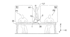
- FIG. 4 is a conceptual diagram showing how the inactivation system 30 is used in a restaurant or cafeteria having a long table 35 where multiple people can line up.
- the air blower 1 and the ultraviolet light irradiation device 2 are placed on a long desk 35 long in the X direction between the seat of the customer P1 and the seat of the customer P2.
- the blower 1 discharges the air sucked from around the blower 1 upward (+Z direction) to form an upward airflow A1.
- the airflow A1 constitutes an airflow surface that separates the small space S1 in which the customer P1 resides and the small space S2 in which the customer P2 resides.
- the ultraviolet light irradiation device 2 emits ultraviolet light (for example, having a spectrum substantially in the wavelength band of 190 to 240 nm, 250 to light having substantially no spectrum in the 280 nm wavelength band).
- ultraviolet light for example, having a spectrum substantially in the wavelength band of 190 to 240 nm, 250 to light having substantially no spectrum in the 280 nm wavelength band.
- the air blower 1 and the ultraviolet light irradiation device 2 can be placed on the long table 35, installation is easy.
- the ultraviolet light in the wavelength band of 250 to 280 nm is present in the wavelength band of 190 to 240 nm.
- an optical filter or the like may be combined and arranged after the light source to realize ultraviolet light emission in the desired wavelength band.
- the inactivation system 30 is arranged between the seats of the customers P1 and P2 lined up in the longitudinal direction of the long table 35, but it is not limited to this. For example, if customers can sit facing each other in the short direction of the long table 35, the deactivation system 30 may be placed between the customers facing each other.
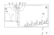
- FIG. 5 is a conceptual diagram showing the use of deactivation system 40 in a theater.
- the deactivation system 40 is arranged, for example, in front of and above the stage of the theater along the width direction (Y direction) of the drop curtain.
- the airflow A1 of the deactivation system 40 separates a small space S1 in which the performer P1 resides and a small space S2 in which the audience P2 (only one of the audience members is labeled in FIG. 5).
- This figure does not show the provision of a deactivation system between each of the spectators P2, it is also possible to provide a deactivation system between the seats of each of the spectators P2.
- the air blown by the blower 1 may be indoor air or outdoor air. Alternatively, air from which pathogens and dust have been removed by a filter or the like may be blown.
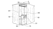
- FIG. 6 is a conceptual diagram showing an inactivation system used in a hospital room with beds for multiple people. As shown in FIG. 6, the hospital bed can draw a curtain 52 around the bed 51 .
- the airflow port 13 and the suction port 15 for forming an airflow surface along the curtain 52 are provided, and the airflow A1 is formed from the airflow port 13 toward the suction port 15. ing.
- a small space where the patient on the bed 51 is located and a small space outside the curtain 52 where other patients or medical personnel are located in the same hospital room are separated.
- ultraviolet light for inactivating pathogens is irradiated toward the airflow A1 in the middle of partitioning the small space, and the pathogens discharged from the patient. inactivate the
- the large-area additional air blowing port 53 is provided on the entire upper side of the bed 51, and the large-area additional suction port 55 is provided on the entire lower side of the bed.
- an airflow A9 directed from the additional blower port 53 to the additional suction port 55 can be formed.
- the air currents A1 and A9 form air currents in the entire small space including the bed 51 . This can further reduce the risk of pathogen infection.
- the curtain 52 facilitates partitioning the small space including the bed 51 and the small space around the bed 51, the curtain 52 is not an essential component of the present invention.
- FIG. 7 is a conceptual diagram showing how the airflow sent out from the blower 1 convects in the room.
- the airflow A1 sent out from the blower port 13 of the blower 1 goes toward the floor F1.
- the airflow A1 is an airflow in the middle of partitioning the small space S1 and the small space S2, and forms an airflow wall.
- the airflow A1 changes its traveling direction by the floor F1 and spreads in the X direction (horizontal direction) as an airflow A2.
- the airflow A2 is an airflow passing through the space below the small space S2 (for example, from the feet to the waist of the person in the small space S2).
- the airflow A2 collides with the wall F2 of the room, it becomes the airflow A3 and advances in the +Z direction.
- the airflow A3 is an airflow rising near the wall F2.
- the airflow A3 changes direction at the ceiling F3 and returns to the blower 1 as an airflow A4.
- the airflow A4 is, for example, an airflow passing through the space above the small space S2. Then, the airflow A4 is sent out from the blower device 1 again as the airflow A1. In this manner, the airflows A1 to A4 convect inside the room.
- Airflows A1 to A3 pass through a position that can be touched by humans, while the upper part of the space through which airflow A4 passes is at a high position near the ceiling F3. Therefore, it is usually difficult for a person to touch the airflow A4.
- the ultraviolet light irradiation device 2 is arranged near the ceiling F3, and irradiates the ultraviolet light L1 to the airflow A4 in the upper part of the space flowing near the ceiling F3.
- the air sent out from the blower 1 is the air after the deactivation treatment. Therefore, the risk of infection with pathogens is low.
- This embodiment shows that the airflows A2 to A4, which are not in the process of being used for partitioning the space after colliding with the floor or wall, may be irradiated with ultraviolet light.
- a wind direction adjusting member may be arranged to guide the direction of the airflow.
- the airflow direction adjusting member 71 having an inclined surface 71a with respect to the airflow A1 changes the direction of the airflow A1 flowing from top to bottom into the +X direction to form an airflow A2.
- the wind direction adjusting member 71 is arranged only at one position, but the wind direction adjusting member may be arranged at a plurality of positions.
- FIG. 7 shows a table with an inclined surface 71a inclined in one direction as the wind direction adjusting member 71
- the wind direction adjusting member 71 does not have to be such a table-like object.
- it may be a plate-like object, or a cylindrical object through which an air current passes.
- the wind direction adjusting member 71 not only a dedicated member manufactured for wind direction adjustment, but also a step such as a step or a block, general articles such as a desk, or furniture can be suitably used.
- the amount of ultraviolet light irradiation per day (8 hours) to the human body is It is specified to be equal to or less than the permissible limit value (TLV: Threshold Limit Value) for each wavelength.
- TLV Threshold Limit Value
- ultraviolet light is emitted toward the airflow A4, which is difficult for humans to touch. It is also possible not to set the irradiation intensity and the irradiation time in consideration of the TLV.
- the ultraviolet light irradiation device may be incorporated in lighting equipment such as fluorescent lamps and LEDs.
- Air blower 2 Ultraviolet light irradiation device 3: Intake device 5: Tables 10, 20, 30, 40: Inactivation system 11: Blades 12: Drive unit 13: Air blow port 15: Suction port 21: Register counter 35: Length Desk 51 : Bed 52 : Curtain 53 : Additional air blower 55 : Additional suction port 71 : Wind direction adjusting members A1, A2, A3, A4, A9 : Airflow L1 : Ultraviolet light S1, S2 : Small space
Landscapes
- Health & Medical Sciences (AREA)
- Engineering & Computer Science (AREA)
- Epidemiology (AREA)
- Mechanical Engineering (AREA)
- General Engineering & Computer Science (AREA)
- Combustion & Propulsion (AREA)
- Chemical & Material Sciences (AREA)
- Life Sciences & Earth Sciences (AREA)
- Animal Behavior & Ethology (AREA)
- General Health & Medical Sciences (AREA)
- Public Health (AREA)
- Veterinary Medicine (AREA)
- Disinfection, Sterilisation Or Deodorisation Of Air (AREA)
Abstract
菌又はウイルスの感染リスクを低下させるシステムを提供する。 本発明のシステムは、人が居ることのできる空間を面で区画するための気流を形成する、送風装置と、前記気流に、菌又はウイルスを不活化させる紫外光を照射する、紫外光照射装置と、を備える、不活化システムである。
Description
この発明は、不活化システム及び不活化方法に関する。
最近、菌又はウイルス等の病原体を含む飛沫が人の口や鼻から飛散することを防ぐために、人と人との間に透明板や透明シート等の遮蔽物(以下、単に「遮蔽物」ということがある。)を配置することにより空間を区画し、感染防止を行う様子が見られる。
また、以前より、有人空間を紫外光で殺菌する方法が知られている。例えば、特許文献1には、室内に浮遊する菌を当該室内の上部空間に移動させて、当該上部空間に紫外光を照射して殺菌することが記載されている。
人と人との間に遮蔽物を配置したとしても、人の口や鼻から排出されるエアロゾルが、室内の空調や外気による気流に乗って、遮蔽物を飛び越えるおそれがある。さらに、遮蔽物を配置すると、人の口や鼻から排出された飛沫が遮蔽物に付着し、乾燥により飛沫がエアロゾル化して気流に乗り、遮蔽物を飛び越えるおそれがある。
飛沫は比較的重く、重力により落下するのに対し、エアロゾルは飛沫よりも小さく軽いため、重力環境下においても僅かな空気の流れに乗って空気中を浮遊できる。そして、エアロゾルは、飛沫と同様に菌又はウイルスを含むことができる。
そして、特許文献1の紫外光殺菌装置は、人と人との間を遮蔽しない。そうすると、特許文献1の紫外光殺菌装置では、菌が紫外光の照射される上部空間へ移動する前に、ある人から排出された菌を、他の人が吸い込むおそれがあり、感染リスクがある。
本発明が解決しようとする課題は、菌又はウイルスの感染リスクを低下させるシステム及び方法を提供することである。
本発明のシステムは、人が居ることのできる空間を面で区画するための気流を形成する、送風装置と、
前記気流に、菌又はウイルスを不活化させる紫外光を照射する、紫外光照射装置と、
を備える、不活化システムである。
前記気流に、菌又はウイルスを不活化させる紫外光を照射する、紫外光照射装置と、
を備える、不活化システムである。
「人が居ることのできる空間」とは、複数の人が立ち入ることのできる空間を表し、実際に人が居るか、又は人が居ないかを問わない。「複数の人が立ち入ることのできる空間」の具体例として、飲食店、食堂、小売店、学校、病院、劇場、スポーツジム、住宅若しくは事業所などの建物内の空間、又は、例えば、自動車、バス、電車もしくは飛行機などの乗り物内の空間を含む。
「空間を面で区画するための気流」とは、ある空間内に面状の気流、すなわち、気流面を形成し、当該気流面が、当該ある空間を第一の小空間と第二の小空間とに分離することを表す。二つの小空間に分離することにより、二つの小空間それぞれに含まれる雰囲気が気流面を越えて混ざりあうことを制限する。ある空間内に二つ以上の気流面を形成し、三つ以上の小空間に区画してもよい。
「菌」とは、原核生物である細菌類、及び真核生物であるカビ等の真菌類など細胞構造を有する原生生物全般を含む。原生生物の場合、「不活化」とは、細胞内のDNAもしくは酵素(タンパク質)又は細胞膜を破壊すること等により死滅させること、又は細胞の増殖機能を取り除くことのいずれかを指す。
「ウイルス」とは、細胞構造を有しないゲノムとしてDNA又はRNAの核酸を有するものである。ウイルスの場合、「不活化」とは、DNA又はRNAを破壊することにより、細胞への感染力を失わせることを指す。
以降、「菌又はウイルス」を病原体ということがある。病原体は、人又は動物の口又は鼻から、呼気、唾、咳又はくしゃみとして飛散する、飛沫、又はエアロゾルに含まれることがある。
前記不活化システムにより、第一の小空間に居る人が、仮に病原体を含む飛沫又はエアロゾルを口又は鼻より排出したとしても、飛沫又はエアロゾルは気流面に阻まれて、第二の小空間へ飛散しにくくなる。さらに、従来の、透明板や透明シートのような遮蔽物がないため、飛沫が遮蔽物に付着することもなく、加えて、遮蔽物の近くに居る人に閉塞感を与えることもない。
さらに、形成した気流に菌又はウイルスを不活化させる紫外光を照射する。これにより、第一の小空間に居る人が排出した、病原体を含む飛沫又はエアロゾルが気流に乗り、当該気流を第二の小空間に居る人が吸込んだとしても、既に病原体を不活化させているため感染リスクは低い。菌又はウイルスを不活化させる紫外光の波長帯域は、例えば、190~280nmである。
感染リスクを低下させることは、国連が主導する持続可能な開発目標(SDGs)の目標3「あらゆる年齢の全ての人々が健康的な生活を確保し、福祉を促進する」に対応し、また、ターゲット3.3「2030年までに、エイズ、結核、マラリア及び顧みられない熱帯病といった伝染病を根絶すると共に、肝炎、水系感染症及びその他の感染症に対処する」に大きく貢献するものである。
前記紫外光は、190~240nmの波長帯域に実質的にスペクトルを有し、250~280nmの波長帯域にスペクトルを実質的に有さない光であり、
前記紫外光は、前記人が触れることのできる低い位置の前記気流に照射されても構わない。これにより、人体に対する安全性が向上するとともに、不活化システムの設計の自由度が向上する。
前記紫外光は、前記人が触れることのできる低い位置の前記気流に照射されても構わない。これにより、人体に対する安全性が向上するとともに、不活化システムの設計の自由度が向上する。
本明細書において、実質的にスペクトルを有する波長帯域とは、発光スペクトルのピーク波長及び当該ピーク波長における光強度に対して30%以上の光強度を示す波長を含む波長帯域を指す。逆に、ある波長帯域に実質的にスペクトルを有しない波長帯域とは、ピーク波長の光強度に対して5%未満の光強度まで抑制された波長帯域を指す。
前記気流によって前記空間を区画する気流面に、前記紫外光を照射しても構わない。これにより、病原体が気流に乗って移動する距離の短いうちに紫外光を照射して不活化できる。詳述すると、送風装置により、空間を面で区画する気流面を形成することで、当該気流面が第一の小空間と第二の小空間とに分離し、飛沫又はエアロゾルが、一方の小空間から他方の小空間へ飛散することを防ぐ。また、空間を区画する気流面に紫外光が照射されているため、例えば、第一の小空間にいる人が排出した病原体を含む飛沫又はエアロゾルが、気流によって第一の小空間内を対流する前に、紫外光の照射によって病原体の不活化を行うことができる。
前記紫外光は、前記人が触れることの困難な空間上部の前記気流に照射されても構わない。これにより、人体に対する安全性が向上するとともに、紫外光照射量(照射強度及び照射時間)の設定可能幅が拡大する。
人が触れることの困難な空間上部とは、多数の人が手を伸ばしても届かない空間であり、例えば、空間を構成する底面(床面)からの高さが2mを超える空間を指す。
前記送風装置は、上から下に向かう気流を形成しても構わない。
前記気流を吸引する吸気装置を備えても構わない。これにより、気流面の乱流化を抑えて、空間を区画しやすくなる。
前記気流による区画により形成された複数の小空間のうち、少なくとも一つの前記小空間には、当該少なくとも一つの小空間全体に気流が形成されても構わない。これにより、全体に気流を形成した小空間からの感染リスクをさらに低下させる。
本発明の不活化方法は、人が居ることのできる空間を面で区画する気流を形成し、前記気流に菌又はウイルスを不活化させる紫外光を照射する。
これにより、菌又はウイルスの感染リスクを低下させるシステム及び方法を提供できる。
紫外光照射装置の一実施形態につき、図面を参照して説明する。なお、以下の各図面は模式的に図示されたものであり、図面上の寸法比は必ずしも実際の寸法比と一致しておらず、各図面間においても寸法比は必ずしも一致していない。
以下において、各図面は、適宜、XYZ座標系を参照しながら説明される。なお、本明細書において、方向を表現する際に、正負の向きを区別する場合には、「+X方向」、「-X方向」のように、正負の符号を付して記載される。正負の向きを区別せずに方向を表現する場合には、単に「X方向」と記載される。すなわち、本明細書において、単に「X方向」と記載されている場合には、「+X方向」と「-X方向」の双方が含まれる。Y方向及びZ方向についても同様である。XYZ座標系では、重力方向は-Z方向と表され、水平面はXY平面と表される。
<第一実施形態>
図1を参照しながら、本発明の不活化システムの第一実施形態を説明する。図1は、飲食店において、不活化システム10の使用される様子を示す概念図である。
図1を参照しながら、本発明の不活化システムの第一実施形態を説明する。図1は、飲食店において、不活化システム10の使用される様子を示す概念図である。
飲食店内には、少なくとも二つの席がX方向に隣り合って配置されている。図1では、客P1の居る席と客P2の居る席とが示されている。各席は、それぞれ、テーブル5と椅子(不図示)とを含む。客P1の居る席と客P2の居る席との間の上方(+Z方向)に、不活化システム10が配置されている。不活化システム10は、送風装置1と紫外光照射装置2を備えている。送風装置1は下方(-Z方向)に向けて気流を形成する。図1では気流を実線の矢印で示し、当該矢印の一つをA1と付している。
図2は、送風装置1と紫外光照射装置2の具体例を示している。送風装置1は、軸C1の回りを回転する羽根11と、羽根11を回転させる駆動部12と、送風口13と、を含む。送風口13は、一方向(本実施形態ではY方向)に延びる形状を呈する。そのため、送風装置1により形成される気流は、気流面を形成する。なお、この送風装置1の具体例は一例であって、これに限られない。送風機構、送風装置1の大きさ又は送風口13の形状が異なってもよい。例えば、複数の小型送風装置を列をなすように並べて、全体として気流面を形成しても構わない。
図1を参照しながら、気流面を形成可能な送風装置1の作用を説明する。送風装置1を連続的に運転させると、送風口13から下方に向かって、YZ面に沿う気流面が形成される。この気流面は、一般に、「エアカーテン」とも呼ばれる。気流面は、一つの大きな空間を、客P1の居る小空間S1と客P2の居る小空間S2とに区画する。これにより、客P1が、仮に病原体を含むエアロゾルを口又は鼻より排出したとしても、エアロゾルは気流A1で構成される気流面に阻まれて、客P2の居る小空間S2への飛散が抑制される。
気流面は平面に限らず、曲面を含んでいても構わない。
気流面は平面に限らず、曲面を含んでいても構わない。
さらに、従来の、透明板や透明シートのような遮蔽物がないため、飛沫が遮蔽物に付着することがない。よって、遮蔽物に付着した飛沫からエアロゾルが形成されない。加えて、遮蔽物がないため、客(P1、P2)に閉塞感を与えにくい。
気流面の厚み(X方向の寸法)は、例えば50mm以上であるとよく、好ましくは100mm以上であるとよく、より好ましくは300mm以上であるとよい。これにより、気流が両空間(S1、S2)を越えて移動しようとする飛沫又はエアロゾルを妨げ易くなる。気流A1の流速は、例えば、0.1m/s以上であるとよく、好ましくは0.3m/s以上であるとよい。これにより安定した気流面を形成できる。気流の流速の上限は、気流面の形成という点において特に限定されないが、他の要因(例えば強い気流が引き起こす塵埃の巻き上げや送風装置1の騒音)を踏まえると、例えば、8m/s以下であるとよく、5.5m/s以下であると好ましい。
図1及び図2を参照して、紫外光照射装置2は、小空間S1と小空間S2とを区画している最中の気流A1に向けて病原体を不活化させる紫外光L1を照射する。紫外光照射装置2は、紫外光L1の進行方向が気流A1の進行方向と交わるように設置する。図1では紫外光照射装置2から照射される光線を破線の矢印で示し、当該矢印の一つをL1と付している。
紫外光L1を気流A1に向けて照射する理由を説明する。図1の場合、気流A1は床F1に向かう。詳細は後述するが、気流A1は、床F1によって進行方向を転換すると、拡散し、空間内を対流するようになる。気流A1を構成する空気が送風装置1に戻り、再び送風装置1より気流として送り出されることもある。ここで、仮に、客P1又は客P2から排出される病原体を含むエアロゾルが気流A1に乗せられると、病原体もまた空間内を対流することになり、感染リスクの低減につながらない。しかしながら、紫外光L1が気流A1に含まれる病原体を不活化するため、エアロゾルが空間内を対流しても問題はない。
紫外光照射装置2は、190~280nmの波長帯域の光を気流に照射する。これにより、気流に含まれる病原体を不活化する。特に、本実施形態では、190~240nmの波長帯域に実質的にスペクトルを有し、250~280nmの波長帯域にスペクトルを実質的に有さない紫外光を使用している。250~280nmの波長帯域の光は、人体に対して悪影響を及ぼすおそれがあるのに対し、190~240nmの波長帯域の光は、人体に対して影響を及ぼすおそれのない、有害性の極めて低い光である。
その結果、安全性が向上するのみならず、紫外光照射装置からの照射光に人が容易に触れることの可能な位置に紫外光照射装置を配置できるため、不活化システムの設計の自由度が向上する。
なお、本明細書において、「190~240nmの波長帯域に実質的にスペクトルを有」するとは、190~240nmの数値範囲に属する少なくとも一部の波長帯域にスペクトルを有することを表すものであって、190~240nmの全ての波長帯域にスペクトルを有することを表すものではないことに留意されたい。波長帯域に関する他の数値範囲についても、同様である。
本実施形態の紫外光照射装置2には、例えば、190nm~240nmである紫外光を放射するエキシマランプが使用される。本実施形態では、発光管の内部にKrClを含む発光ガスが封入されたKrClエキシマランプを使用しており、主たるピーク波長が222nm又はその近傍の紫外光を出射する。
エキシマランプは、KrClエキシマランプに限らない。例えば、発光管の内部にKrBrを含む発光ガスが封入されたKrBrエキシマランプや、発光管の内部にArFを含む発光ガスが封入されたArFエキシマランプを使用しても構わない。KrBrエキシマランプは、主たるピーク波長が207nm又はその近傍の紫外光を出射する。また、エキシマランプの他に、固体光源を使用しても構わない。
人や動物に対する安全性をさらに高める観点から、光源部から出射される紫外光は、波長範囲が190nm以上237nm以下の範囲内であることがより好ましく、190nm以上235nm以下の範囲内であることがさらにより好ましく、190nm以上230nm以下の範囲内であることが特に好ましい。
送風装置1及び紫外光照射装置2の配置高さは、区画したい空間の高さに合わせて設定できる。図1のように客が多くの時間を椅子に座って過ごす飲食店のような場所では、送風装置1及び紫外光照射装置2の配置高さを、床F1から1.5m~2mにしてもよい。
送風装置1及び紫外光照射装置2は、床F1から延びる支柱(不図示)によって支持しても構わないし、天井(不図示)から吊り下げても構わない。
送風装置1及び紫外光照射装置2は、床F1から延びる支柱(不図示)によって支持しても構わないし、天井(不図示)から吊り下げても構わない。
図1では、小空間S1と小空間S2にそれぞれ客が居る様子を示したが、小空間S1と小空間S2は、それぞれ、人が立ち入ることのできる空間であって、それぞれの空間に客がいない状態であってもよい。現実に客が居る、又は居ないにかかわらず、客が滞在可能な席を備える空間を、「人が居ることのできる空間」とする。また、図1では、飲食店内で不活化システムを使用する例を説明したが、これに限らず、複数の人が立ち入ることのできる空間であれば飲食店以外でも適用可能である。なお、「席」は机と椅子を必須の構成とするものではない。例えば、立食形式の飲食店の場合を想定すれば、椅子は必須ではなく、乗り物の車内・機内を想定すれば、机は必須ではないことが理解される。
図1では、小空間(S1、S2)それぞれに客が一人ずついる様子を描写しているが、小空間(S1、S2)に複数の人が居ても構わない。
[第一変形例]
図3を参照しながら、第一実施形態の第一変形例を説明する。以下に述べる以外の事項は、上述した実施形態と同様に実施できる。第二変形例以降又は第二実施形態以降も同様に実施できる。
図3を参照しながら、第一実施形態の第一変形例を説明する。以下に述べる以外の事項は、上述した実施形態と同様に実施できる。第二変形例以降又は第二実施形態以降も同様に実施できる。
図3は、小売店で商品の会計を行うレジカウンタにおいて、不活化システム20の使用される様子を示す概念図である。レジカウンタ21を隔てて買い物客P1と店員P2が向かい合い、会計のために、店員P2は商品のバーコードを読み取っている。不活化システムは、レジカウンタ21の上方に配置された送風装置1及び紫外光照射装置2と、レジカウンタ21に配置された吸気装置3とを備える。
送風装置1により形成される気流A1は、買い物客P1の居る小空間S1と店員P2の居る小空間S2とを区画する気流面を形成する。これにより、買い物客P1又は店員P2が、仮に病原体を含む飛沫又はエアロゾルを口又は鼻より排出したとしても、飛沫又はエアロゾルは気流面に阻まれて、他方の人の居る小空間へ飛散しにくい。さらに、紫外光照射装置2は、小空間S1と小空間S2とを区画している最中の気流A1に向かって紫外光(例えば、190~240nmの波長帯域に実質的にスペクトルを有し、250~280nmの波長帯域にスペクトルを実質的に有さない光)を照射する。これにより、気流A1に含まれる病原体、又は、レジカウンタ21に付着した飛沫に含まれる病原体を不活化する。
吸気装置3は、吸引口15と排気機構(不図示)とを備え、吸引口15より気流A1を吸引する。吸気装置3を設けることにより、気流面の乱流化を抑えて、空間を区画しやすくなる。吸引口15は、吸引口15に物を置くことのできるように、例えば、グレーチング構造を呈する。吸気装置3により吸引された気流は、レジカウンタ21の下方の足元付近から排出しても構わないし、店外に排出しても構わない。
吸気装置3の吸引量は、送風装置1の送風量と釣り合うように設定してもよいし、吸気装置3の吸引量を送風装置1の送風量よりも大きくなるように設定してもよい。また、送風口13の形状と吸引口15の形状と同じ形状にしてもよい。なお、吸気装置3は任意の設備であって、不活化システムは吸気装置3を有していなくても構わない。
[第二変形例]
図4を参照しながら、第一実施形態の第二変形例を説明する。図4は、複数人が並ぶことのできる長机35を有する飲食店や食堂において、不活化システム30を使用する様子を示す概念図である。客P1の席と客P2の席との間の、X方向に長い長机35上に、送風装置1及び紫外光照射装置2を載置する。送風装置1は、送風装置1の周囲から吸込んだ空気を上方向(+Z方向)へ排出し、上方へ向かう気流A1を形成する。気流A1は、客P1の居る小空間S1と客P2の居る小空間S2とを区画する気流面を構成する。紫外光照射装置2は、小空間S1と小空間S2とを区画している最中の気流A1に向かって紫外光(例えば、190~240nmの波長帯域に実質的にスペクトルを有し、250~280nmの波長帯域にスペクトルを実質的に有さない光)を照射する。この例では送風装置1と紫外光照射装置2が長机35に載置すればよいため、設置が簡単である。
図4を参照しながら、第一実施形態の第二変形例を説明する。図4は、複数人が並ぶことのできる長机35を有する飲食店や食堂において、不活化システム30を使用する様子を示す概念図である。客P1の席と客P2の席との間の、X方向に長い長机35上に、送風装置1及び紫外光照射装置2を載置する。送風装置1は、送風装置1の周囲から吸込んだ空気を上方向(+Z方向)へ排出し、上方へ向かう気流A1を形成する。気流A1は、客P1の居る小空間S1と客P2の居る小空間S2とを区画する気流面を構成する。紫外光照射装置2は、小空間S1と小空間S2とを区画している最中の気流A1に向かって紫外光(例えば、190~240nmの波長帯域に実質的にスペクトルを有し、250~280nmの波長帯域にスペクトルを実質的に有さない光)を照射する。この例では送風装置1と紫外光照射装置2が長机35に載置すればよいため、設置が簡単である。
なお、波長190~240nmの波長帯域の紫外光を放射する紫外光照射装置である場合、250~280nmの波長帯域の紫外光は、波長190~240nmの波長帯域に存在するピーク波長の光強度に対して5%未満の光強度に抑制することが望ましく、さらには、3%未満の光強度に抑制することが望ましく、さらには、1%未満の光強度に抑制することが望ましい。所望外の波長帯域の紫外光を放射する光源を使用する場合でも、例えば、光源の後段に光学フィルタ等を組み合わせて配置することにより、所望の波長帯域の紫外光放射を実現させてもよい。
この変形例では、長机35の長手方向に並ぶ客P1と客P2の席の間に不活化システム30を配置することを説明したが、これに限らない。例えば、長机35の短手方向に客が対向するように座ることのできる場合には、対向する客の間に不活化システム30を配置しても構わない。
[第三変形例]
図5を参照しながら、第一実施形態の第三変形例を説明する。図5は、劇場において不活化システム40を使用する様子を示す概念図である。不活化システム40は、例えば、劇場の舞台の前方且つ上方に、緞帳の幅方向(Y方向)に沿って配置される。そして、不活化システム40の気流A1は、演者P1の居る小空間S1と観客P2(図5では観客の一人のみに符号を付している)の居る小空間S2とを区画する。この図では、観客P2のそれぞれの間に不活化システムを備えることを示していないが、観客P2それぞれの席の間にも不活化システムを備えても構わない。送風装置1より送風する空気は、屋内の空気でも構わないし屋外の空気でも構わない。また、フィルタ等で病原体や塵埃を取り除いた空気を送風しても構わない。
図5を参照しながら、第一実施形態の第三変形例を説明する。図5は、劇場において不活化システム40を使用する様子を示す概念図である。不活化システム40は、例えば、劇場の舞台の前方且つ上方に、緞帳の幅方向(Y方向)に沿って配置される。そして、不活化システム40の気流A1は、演者P1の居る小空間S1と観客P2(図5では観客の一人のみに符号を付している)の居る小空間S2とを区画する。この図では、観客P2のそれぞれの間に不活化システムを備えることを示していないが、観客P2それぞれの席の間にも不活化システムを備えても構わない。送風装置1より送風する空気は、屋内の空気でも構わないし屋外の空気でも構わない。また、フィルタ等で病原体や塵埃を取り除いた空気を送風しても構わない。
<第二実施形態>
図6を参照しながら、第二実施形態を説明する。図6は、複数人の病床が配置された病室において使用される不活化システムを示す概念図である。図6に示されるように、病床は、ベッド51の回りにカーテン52を引くことができる。
図6を参照しながら、第二実施形態を説明する。図6は、複数人の病床が配置された病室において使用される不活化システムを示す概念図である。図6に示されるように、病床は、ベッド51の回りにカーテン52を引くことができる。
このような病床において、本実施形態では、カーテン52に沿って気流面を形成するための送風口13と吸引口15とを有し、送風口13から吸引口15に向かって気流A1を形成している。これにより、ベッド51に居る患者の居る小空間と、カーテン52の外で、同じ病室に居る他の患者又は医療従事者の居る小空間とを区画する。そして、送風口13の近くに配置された紫外光照射装置2から、小空間を区画している最中の気流A1に向かって病原体を不活化させる紫外光を照射し、患者から排出される病原体を不活化させる。
さらに、本実施形態では、ベッド51の上方全体に大面積の追加送風口53と、ベッドの下方全体に大面積の追加吸引口55とを有する。これにより、追加送風口53から追加吸引口55へ向かう気流A9を形成できる。その結果、気流A1と気流A9により、ベッド51を含む小空間全体に気流を形成する。これにより、病原体の感染リスクをさらに低減できる。
なお、ベッド51を含む小空間とベッド51の周囲の小空間とを区画するに際し、カーテン52の存在は空間の区画を促進するが、カーテン52は、本発明における必須の構成ではない。
<第三実施形態>
図7を参照しながら、第三実施形態を説明する。図7は、送風装置1から送り出される気流が室内を対流する様子を示す概念図である。送風装置1の送風口13から送り出された気流A1は床F1に向かう。気流A1は、小空間S1と小空間S2とを区画している最中の気流であり、気流の壁を形成する。図7に示されるように、気流A1は、床F1によって進行方向を転換し、気流A2としてX方向(水平方向)に拡散していく。気流A2は、小空間S2の下方(例えば、小空間S2に居る人の足元から腰部まで)の空間を通過する気流である。気流A2が部屋の壁F2に衝突すると、気流A3となって+Z方向へ進む。気流A3は、壁F2付近を上昇する気流である。気流A3は、天井F3で向きを変えて、気流A4となって送風装置1に戻る。気流A4は、例えば、小空間S2の上方の空間を通過する気流である。そして、気流A4は、気流A1として再び送風装置1より送り出される。このようにして、気流A1~A4は室内を対流する。
図7を参照しながら、第三実施形態を説明する。図7は、送風装置1から送り出される気流が室内を対流する様子を示す概念図である。送風装置1の送風口13から送り出された気流A1は床F1に向かう。気流A1は、小空間S1と小空間S2とを区画している最中の気流であり、気流の壁を形成する。図7に示されるように、気流A1は、床F1によって進行方向を転換し、気流A2としてX方向(水平方向)に拡散していく。気流A2は、小空間S2の下方(例えば、小空間S2に居る人の足元から腰部まで)の空間を通過する気流である。気流A2が部屋の壁F2に衝突すると、気流A3となって+Z方向へ進む。気流A3は、壁F2付近を上昇する気流である。気流A3は、天井F3で向きを変えて、気流A4となって送風装置1に戻る。気流A4は、例えば、小空間S2の上方の空間を通過する気流である。そして、気流A4は、気流A1として再び送風装置1より送り出される。このようにして、気流A1~A4は室内を対流する。
気流A1~A3は人が触れることのできる位置を通過するのに対し、気流A4が通る空間上部は、天井F3近くの高い位置にある。そのため、通常、人が気流A4に触れることは困難である。本実施形態において、紫外光照射装置2は天井F3近くに配置され、天井F3近くを流れる空間上部の気流A4に紫外光L1を照射する。再び送風装置1より送り出される前の気流A4に対して紫外光を照射するため、送風装置1から送り出される空気は、不活化処理後の空気である。よって、病原体の感染リスクは低い。この実施形態は、床や壁などに衝突した後の、空間の区画に利用される最中ではない気流A2~A4に対して紫外光を照射しても構わないことを表している。
乱流を抑制しつつ円滑に気流A1から気流A4まで向かわせるために、気流の向きを誘導するための風向調整部材を配置しても構わない。図7において、気流A1に対して傾斜面71aを有する風向調整部材71は、上から下に流れる気流A1の向きを+X方向に変えて、気流A2にする。図7では風向調整部材71を一箇所しか配置していないが、風向調整部材を複数個所に配置してもよい。
また、図7では、風向調整部材71として、一方向に傾斜する傾斜面71aを備えた台を示しているが、風向調整部材71はこのような台状の物体でなくてもよい。例えば、板状の物体でもよく、気流を内部に通す筒状の物体でもよい。風向調整部材71として、風向調整のために製造された専用部材だけでなく、例えば、踏み台もしくはブロック等の段差、又は机といった一般用品又は家具もまた、好適に用いられる。
人を含む環境に対する紫外光照射は、その照射量を抑えることが求められる場合がある。例えば、ACGIH(American Conference of Governmental Industrial Hygienists:米国産業衛生専門家会議)、又はJIS Z 8812(有害紫外放射の測定方法)では、人体への1日(8時間)あたりの紫外光照射量が、波長ごとに許容限界値(TLV:Threshold Limit Value)以下となるように、規定されている。
本実施形態では、人が触れることの困難な位置にある気流A4に向かって、紫外光を照射しているため、190~280nmの波長帯域のうち、特に安全性の高い波長帯域を選択しなくても構わないし、TLVを考慮して照射強度や照射時間を設定しなくても構わない。
以上で、不活化システムの各実施形態及び変形例を説明した。しかしながら、本発明は上記した実施形態に何ら限定されるものではなく、本発明の趣旨を逸脱しない範囲内で、上記の実施形態を組み合わせたり、種々の変更又は改良を加えたりすることができる。例えば、変更の例として、例えば、上記紫外光照射装置を、蛍光灯やLED等の照明設備に内蔵させても構わない。
1 :送風装置
2 :紫外光照射装置
3 :吸気装置
5 :テーブル
10、20、30、40 :不活化システム
11 :羽根
12 :駆動部
13 :送風口
15 :吸引口
21 :レジカウンタ
35 :長机
51 :ベッド
52 :カーテン
53 :追加送風口
55 :追加吸引口
71 :風向調整部材
A1、A2、A3、A4、A9 :気流
L1 :紫外光
S1、S2:小空間
2 :紫外光照射装置
3 :吸気装置
5 :テーブル
10、20、30、40 :不活化システム
11 :羽根
12 :駆動部
13 :送風口
15 :吸引口
21 :レジカウンタ
35 :長机
51 :ベッド
52 :カーテン
53 :追加送風口
55 :追加吸引口
71 :風向調整部材
A1、A2、A3、A4、A9 :気流
L1 :紫外光
S1、S2:小空間
Claims (8)
- 人が居ることのできる空間を面で区画するための気流を形成する、送風装置と、
前記気流に、菌又はウイルスを不活化させる紫外光を照射する、紫外光照射装置と、
を備えることを特徴とする、不活化システム。 - 前記紫外光は、190~240nmの波長帯域に実質的にスペクトルを有し、250~280nmの波長帯域にスペクトルを実質的に有さない光であり、
前記紫外光は、前記人が触れることのできる低い位置の前記気流に照射されることを特徴とする、請求項1に記載の不活化システム。 - 前記気流によって前記空間を区画する気流面に、前記紫外光を照射することを特徴とする請求項1に記載の不活化システム。
- 前記紫外光は、前記人が触れることの困難な空間上部の前記気流に照射されることを特徴とする、請求項1に記載の不活化システム。
- 前記送風装置は、上から下に向かう気流を形成することを特徴とする、請求項1~4のいずれか一項に記載の不活化システム。
- 前記気流を吸引する吸気装置を備える、請求項1~4のいずれか一項に記載の不活化システム。
- 前記気流による区画により形成された複数の小空間のうち、少なくとも一つの前記小空間には、当該少なくとも一つの小空間全体に気流が形成されていることを特徴とする、請求項1~4のいずれか一項に記載の不活化システム。
- 人が居ることのできる空間を面で区画するための気流を形成し、
前記気流に菌又はウイルスを不活化させる紫外光を照射することを特徴とする、不活化方法。
Applications Claiming Priority (2)
| Application Number | Priority Date | Filing Date | Title |
|---|---|---|---|
| JP2021089030A JP2022181845A (ja) | 2021-05-27 | 2021-05-27 | 不活化システム及び不活化方法 |
| JP2021-089030 | 2021-05-27 |
Publications (1)
| Publication Number | Publication Date |
|---|---|
| WO2022249684A1 true WO2022249684A1 (ja) | 2022-12-01 |
Family
ID=84229797
Family Applications (1)
| Application Number | Title | Priority Date | Filing Date |
|---|---|---|---|
| PCT/JP2022/013128 Ceased WO2022249684A1 (ja) | 2021-05-27 | 2022-03-22 | 不活化システム及び不活化方法 |
Country Status (2)
| Country | Link |
|---|---|
| JP (1) | JP2022181845A (ja) |
| WO (1) | WO2022249684A1 (ja) |
Citations (8)
| Publication number | Priority date | Publication date | Assignee | Title |
|---|---|---|---|---|
| JP2000217561A (ja) * | 1999-02-02 | 2000-08-08 | Sanyo Electric Co Ltd | クリーンテーブル |
| KR20110052006A (ko) * | 2009-11-12 | 2011-05-18 | 차흥식 | 살균용 에어커튼 |
| KR20170114491A (ko) * | 2016-04-05 | 2017-10-16 | 김경숙 | 자외선 운무 에어커튼장치 |
| JP6669845B1 (ja) * | 2018-12-25 | 2020-03-18 | 日機装株式会社 | 感染抑制装置 |
| JP3229800U (ja) * | 2020-07-22 | 2020-12-17 | 株式会社センテック | 除菌機能を有する垂直気流による飛沫感染防止装置 |
| JP2021010403A (ja) * | 2019-07-03 | 2021-02-04 | ウシオ電機株式会社 | 殺菌装置 |
| WO2022004351A1 (ja) * | 2020-07-01 | 2022-01-06 | 未来を拓く合同会社 | エアカーテン装置及び殺菌送風装置 |
| JP2022014834A (ja) * | 2020-07-07 | 2022-01-20 | 都市未来計画株式会社 | ウイルスエアシールド装置 |
-
2021
- 2021-05-27 JP JP2021089030A patent/JP2022181845A/ja not_active Abandoned
-
2022
- 2022-03-22 WO PCT/JP2022/013128 patent/WO2022249684A1/ja not_active Ceased
Patent Citations (8)
| Publication number | Priority date | Publication date | Assignee | Title |
|---|---|---|---|---|
| JP2000217561A (ja) * | 1999-02-02 | 2000-08-08 | Sanyo Electric Co Ltd | クリーンテーブル |
| KR20110052006A (ko) * | 2009-11-12 | 2011-05-18 | 차흥식 | 살균용 에어커튼 |
| KR20170114491A (ko) * | 2016-04-05 | 2017-10-16 | 김경숙 | 자외선 운무 에어커튼장치 |
| JP6669845B1 (ja) * | 2018-12-25 | 2020-03-18 | 日機装株式会社 | 感染抑制装置 |
| JP2021010403A (ja) * | 2019-07-03 | 2021-02-04 | ウシオ電機株式会社 | 殺菌装置 |
| WO2022004351A1 (ja) * | 2020-07-01 | 2022-01-06 | 未来を拓く合同会社 | エアカーテン装置及び殺菌送風装置 |
| JP2022014834A (ja) * | 2020-07-07 | 2022-01-20 | 都市未来計画株式会社 | ウイルスエアシールド装置 |
| JP3229800U (ja) * | 2020-07-22 | 2020-12-17 | 株式会社センテック | 除菌機能を有する垂直気流による飛沫感染防止装置 |
Also Published As
| Publication number | Publication date |
|---|---|
| JP2022181845A (ja) | 2022-12-08 |
Similar Documents
| Publication | Publication Date | Title |
|---|---|---|
| JP5859960B2 (ja) | 微生物及び空気中の健康有害物質の広がりを低減するための並びに/又は微生物及び空気中の健康有害物質から保護するための装置及び方法 | |
| Bolashikov et al. | Methods for air cleaning and protection of building occupants from airborne pathogens | |
| KR102297559B1 (ko) | 방역형 공기정화기 | |
| JP3229800U (ja) | 除菌機能を有する垂直気流による飛沫感染防止装置 | |
| JP2020175258A (ja) | 毒性対象減消装置 | |
| US12582736B2 (en) | Coronavirus (COVID-19) air sanitization/isolation system with anti-virus curtain walls | |
| US11592196B2 (en) | Ventilation system and method for killing airborne infectious bacteria, viruses and other pathogens | |
| KR102240857B1 (ko) | 감염 차단 기능을 구비한 테이블 | |
| JP2022051458A (ja) | 雰囲気遮断浄化装置、エアロゾル浄化方法、フィットネスクラブ、医療設備、及びイベント会場 | |
| JP2022014834A (ja) | ウイルスエアシールド装置 | |
| US11154634B1 (en) | Ultraviolet light fixture | |
| JP7289338B2 (ja) | カプセルベッド及びカプセルベッド結合体 | |
| US11826499B2 (en) | System for treating air | |
| JP2022181845A (ja) | 不活化システム及び不活化方法 | |
| WO2022004351A1 (ja) | エアカーテン装置及び殺菌送風装置 | |
| US20230285626A1 (en) | Table-top apparatus for generating a substantially microbe-inactivated room zone | |
| WO2022150718A1 (en) | Far-uvs device for use in inactivating airborne pathogens | |
| US20210348784A1 (en) | Breathing zone ventillation system | |
| US20220233738A1 (en) | Air Sterilizer | |
| CA3092226A1 (en) | System, components thereof, and methods for reducing risk of transmission of airborne infectious disease in enclosed spaces | |
| US12251502B2 (en) | Ultraviolet light radiation disinfection fixture | |
| KR200496773Y1 (ko) | 실내공기 중에 포함되는 유해세균 멸균처리용 식탁 | |
| ES3006989T3 (en) | Air sanitation device by emission of a barrier of ultraviolet radiation in an air flow | |
| CN116642237A (zh) | 个人空间空气安全系统 | |
| HK40099198A (zh) | 通过在气流中发射紫外辐射屏障的空气卫生装置 |
Legal Events
| Date | Code | Title | Description |
|---|---|---|---|
| 121 | Ep: the epo has been informed by wipo that ep was designated in this application |
Ref document number: 22810961 Country of ref document: EP Kind code of ref document: A1 |
|
| NENP | Non-entry into the national phase |
Ref country code: DE |
|
| 122 | Ep: pct application non-entry in european phase |
Ref document number: 22810961 Country of ref document: EP Kind code of ref document: A1 |