WO2022246765A1 - Nickel oxide particles and method for producing the same - Google Patents
Nickel oxide particles and method for producing the same Download PDFInfo
- Publication number
- WO2022246765A1 WO2022246765A1 PCT/CN2021/096527 CN2021096527W WO2022246765A1 WO 2022246765 A1 WO2022246765 A1 WO 2022246765A1 CN 2021096527 W CN2021096527 W CN 2021096527W WO 2022246765 A1 WO2022246765 A1 WO 2022246765A1
- Authority
- WO
- WIPO (PCT)
- Prior art keywords
- nickel oxide
- oxide particles
- molybdenum
- compound
- mass
- Prior art date
Links
- 229910000480 nickel oxide Inorganic materials 0.000 title claims abstract description 262
- 239000002245 particle Substances 0.000 title claims abstract description 262
- GNRSAWUEBMWBQH-UHFFFAOYSA-N oxonickel Chemical compound [Ni]=O GNRSAWUEBMWBQH-UHFFFAOYSA-N 0.000 title claims abstract description 240
- 238000004519 manufacturing process Methods 0.000 title claims abstract description 50
- 238000001354 calcination Methods 0.000 claims abstract description 78
- 150000002752 molybdenum compounds Chemical class 0.000 claims abstract description 62
- 239000005078 molybdenum compound Substances 0.000 claims abstract description 61
- ZOKXTWBITQBERF-UHFFFAOYSA-N Molybdenum Chemical compound [Mo] ZOKXTWBITQBERF-UHFFFAOYSA-N 0.000 claims abstract description 58
- 229910052750 molybdenum Inorganic materials 0.000 claims abstract description 58
- 239000011733 molybdenum Substances 0.000 claims abstract description 56
- 239000002344 surface layer Substances 0.000 claims abstract description 42
- 150000002816 nickel compounds Chemical class 0.000 claims abstract description 38
- JKQOBWVOAYFWKG-UHFFFAOYSA-N molybdenum trioxide Chemical compound O=[Mo](=O)=O JKQOBWVOAYFWKG-UHFFFAOYSA-N 0.000 claims abstract description 16
- 150000001875 compounds Chemical class 0.000 claims abstract description 15
- ZLMJMSJWJFRBEC-UHFFFAOYSA-N Potassium Chemical compound [K] ZLMJMSJWJFRBEC-UHFFFAOYSA-N 0.000 claims abstract description 13
- 229910052700 potassium Inorganic materials 0.000 claims abstract description 13
- 239000011591 potassium Substances 0.000 claims abstract description 13
- MEFBJEMVZONFCJ-UHFFFAOYSA-N molybdate Chemical compound [O-][Mo]([O-])(=O)=O MEFBJEMVZONFCJ-UHFFFAOYSA-N 0.000 claims abstract description 10
- 238000007561 laser diffraction method Methods 0.000 claims abstract description 9
- 238000000790 scattering method Methods 0.000 claims abstract description 9
- 239000011684 sodium molybdate Substances 0.000 claims abstract description 7
- 235000015393 sodium molybdate Nutrition 0.000 claims abstract description 7
- TVXXNOYZHKPKGW-UHFFFAOYSA-N sodium molybdate (anhydrous) Chemical compound [Na+].[Na+].[O-][Mo]([O-])(=O)=O TVXXNOYZHKPKGW-UHFFFAOYSA-N 0.000 claims abstract description 7
- NMHMDUCCVHOJQI-UHFFFAOYSA-N lithium molybdate Chemical compound [Li+].[Li+].[O-][Mo]([O-])(=O)=O NMHMDUCCVHOJQI-UHFFFAOYSA-N 0.000 claims abstract description 5
- 238000009826 distribution Methods 0.000 claims description 20
- 238000004458 analytical method Methods 0.000 claims description 19
- 238000005211 surface analysis Methods 0.000 claims description 14
- 239000000203 mixture Substances 0.000 description 35
- PXHVJJICTQNCMI-UHFFFAOYSA-N Nickel Chemical compound [Ni] PXHVJJICTQNCMI-UHFFFAOYSA-N 0.000 description 28
- 239000000843 powder Substances 0.000 description 24
- 230000004907 flux Effects 0.000 description 23
- 238000004833 X-ray photoelectron spectroscopy Methods 0.000 description 20
- 238000000034 method Methods 0.000 description 20
- 238000002156 mixing Methods 0.000 description 18
- 150000002736 metal compounds Chemical class 0.000 description 17
- 238000005259 measurement Methods 0.000 description 15
- -1 molybdate compound Chemical class 0.000 description 15
- 230000000052 comparative effect Effects 0.000 description 12
- NLPVCCRZRNXTLT-UHFFFAOYSA-N dioxido(dioxo)molybdenum;nickel(2+) Chemical compound [Ni+2].[O-][Mo]([O-])(=O)=O NLPVCCRZRNXTLT-UHFFFAOYSA-N 0.000 description 12
- 229910000476 molybdenum oxide Inorganic materials 0.000 description 12
- 229910052759 nickel Inorganic materials 0.000 description 12
- PQQKPALAQIIWST-UHFFFAOYSA-N oxomolybdenum Chemical compound [Mo]=O PQQKPALAQIIWST-UHFFFAOYSA-N 0.000 description 12
- 238000004876 x-ray fluorescence Methods 0.000 description 12
- 239000003795 chemical substances by application Substances 0.000 description 11
- 239000013078 crystal Substances 0.000 description 11
- 238000002441 X-ray diffraction Methods 0.000 description 10
- 150000003112 potassium compounds Chemical class 0.000 description 10
- 238000007716 flux method Methods 0.000 description 9
- 150000003388 sodium compounds Chemical class 0.000 description 7
- HEMHJVSKTPXQMS-UHFFFAOYSA-M Sodium hydroxide Chemical compound [OH-].[Na+] HEMHJVSKTPXQMS-UHFFFAOYSA-M 0.000 description 6
- 238000002844 melting Methods 0.000 description 6
- 230000008018 melting Effects 0.000 description 6
- 238000010298 pulverizing process Methods 0.000 description 6
- 239000011734 sodium Substances 0.000 description 6
- 239000000463 material Substances 0.000 description 5
- 230000007246 mechanism Effects 0.000 description 5
- DGAQECJNVWCQMB-PUAWFVPOSA-M Ilexoside XXIX Chemical compound C[C@@H]1CC[C@@]2(CC[C@@]3(C(=CC[C@H]4[C@]3(CC[C@@H]5[C@@]4(CC[C@@H](C5(C)C)OS(=O)(=O)[O-])C)C)[C@@H]2[C@]1(C)O)C)C(=O)O[C@H]6[C@@H]([C@H]([C@@H]([C@H](O6)CO)O)O)O.[Na+] DGAQECJNVWCQMB-PUAWFVPOSA-M 0.000 description 4
- 230000003197 catalytic effect Effects 0.000 description 4
- 239000000919 ceramic Substances 0.000 description 4
- 230000001186 cumulative effect Effects 0.000 description 4
- 230000000694 effects Effects 0.000 description 4
- 238000001704 evaporation Methods 0.000 description 4
- 239000007791 liquid phase Substances 0.000 description 4
- 239000002994 raw material Substances 0.000 description 4
- 238000001878 scanning electron micrograph Methods 0.000 description 4
- 229910052708 sodium Inorganic materials 0.000 description 4
- 238000005406 washing Methods 0.000 description 4
- XLYOFNOQVPJJNP-UHFFFAOYSA-N water Substances O XLYOFNOQVPJJNP-UHFFFAOYSA-N 0.000 description 4
- 229910052727 yttrium Inorganic materials 0.000 description 4
- 229910052783 alkali metal Inorganic materials 0.000 description 3
- 229910052784 alkaline earth metal Inorganic materials 0.000 description 3
- 229940043430 calcium compound Drugs 0.000 description 3
- 150000001674 calcium compounds Chemical class 0.000 description 3
- 150000002681 magnesium compounds Chemical class 0.000 description 3
- 229910052751 metal Inorganic materials 0.000 description 3
- 239000002184 metal Substances 0.000 description 3
- 239000004570 mortar (masonry) Substances 0.000 description 3
- 150000002815 nickel Chemical class 0.000 description 3
- LGQLOGILCSXPEA-UHFFFAOYSA-L nickel sulfate Chemical compound [Ni+2].[O-]S([O-])(=O)=O LGQLOGILCSXPEA-UHFFFAOYSA-L 0.000 description 3
- 229910000363 nickel(II) sulfate Inorganic materials 0.000 description 3
- 238000000859 sublimation Methods 0.000 description 3
- 230000008022 sublimation Effects 0.000 description 3
- NLXLAEXVIDQMFP-UHFFFAOYSA-N Ammonium chloride Substances [NH4+].[Cl-] NLXLAEXVIDQMFP-UHFFFAOYSA-N 0.000 description 2
- VHUUQVKOLVNVRT-UHFFFAOYSA-N Ammonium hydroxide Chemical compound [NH4+].[OH-] VHUUQVKOLVNVRT-UHFFFAOYSA-N 0.000 description 2
- XKRFYHLGVUSROY-UHFFFAOYSA-N Argon Chemical compound [Ar] XKRFYHLGVUSROY-UHFFFAOYSA-N 0.000 description 2
- IJGRMHOSHXDMSA-UHFFFAOYSA-N Atomic nitrogen Chemical compound N#N IJGRMHOSHXDMSA-UHFFFAOYSA-N 0.000 description 2
- CURLTUGMZLYLDI-UHFFFAOYSA-N Carbon dioxide Chemical compound O=C=O CURLTUGMZLYLDI-UHFFFAOYSA-N 0.000 description 2
- 230000002776 aggregation Effects 0.000 description 2
- 238000004220 aggregation Methods 0.000 description 2
- QGZKDVFQNNGYKY-UHFFFAOYSA-N ammonia Natural products N QGZKDVFQNNGYKY-UHFFFAOYSA-N 0.000 description 2
- 235000011114 ammonium hydroxide Nutrition 0.000 description 2
- QVGXLLKOCUKJST-UHFFFAOYSA-N atomic oxygen Chemical compound [O] QVGXLLKOCUKJST-UHFFFAOYSA-N 0.000 description 2
- 230000015572 biosynthetic process Effects 0.000 description 2
- 238000006243 chemical reaction Methods 0.000 description 2
- QXYJCZRRLLQGCR-UHFFFAOYSA-N dioxomolybdenum Chemical compound O=[Mo]=O QXYJCZRRLLQGCR-UHFFFAOYSA-N 0.000 description 2
- 238000010332 dry classification Methods 0.000 description 2
- 230000005496 eutectics Effects 0.000 description 2
- 238000011156 evaluation Methods 0.000 description 2
- 230000008020 evaporation Effects 0.000 description 2
- 239000000446 fuel Substances 0.000 description 2
- 238000003837 high-temperature calcination Methods 0.000 description 2
- 150000002604 lanthanum compounds Chemical class 0.000 description 2
- 239000010410 layer Substances 0.000 description 2
- 229910000008 nickel(II) carbonate Inorganic materials 0.000 description 2
- ZULUUIKRFGGGTL-UHFFFAOYSA-L nickel(ii) carbonate Chemical compound [Ni+2].[O-]C([O-])=O ZULUUIKRFGGGTL-UHFFFAOYSA-L 0.000 description 2
- BFDHFSHZJLFAMC-UHFFFAOYSA-L nickel(ii) hydroxide Chemical compound [OH-].[OH-].[Ni+2] BFDHFSHZJLFAMC-UHFFFAOYSA-L 0.000 description 2
- KBJMLQFLOWQJNF-UHFFFAOYSA-N nickel(ii) nitrate Chemical compound [Ni+2].[O-][N+]([O-])=O.[O-][N+]([O-])=O KBJMLQFLOWQJNF-UHFFFAOYSA-N 0.000 description 2
- SIWVEOZUMHYXCS-UHFFFAOYSA-N oxo(oxoyttriooxy)yttrium Chemical compound O=[Y]O[Y]=O SIWVEOZUMHYXCS-UHFFFAOYSA-N 0.000 description 2
- 229910052760 oxygen Inorganic materials 0.000 description 2
- 239000001301 oxygen Substances 0.000 description 2
- 238000010587 phase diagram Methods 0.000 description 2
- BWHMMNNQKKPAPP-UHFFFAOYSA-L potassium carbonate Chemical compound [K+].[K+].[O-]C([O-])=O BWHMMNNQKKPAPP-UHFFFAOYSA-L 0.000 description 2
- 238000000634 powder X-ray diffraction Methods 0.000 description 2
- BVKZGUZCCUSVTD-UHFFFAOYSA-L Carbonate Chemical compound [O-]C([O-])=O BVKZGUZCCUSVTD-UHFFFAOYSA-L 0.000 description 1
- VEXZGXHMUGYJMC-UHFFFAOYSA-M Chloride anion Chemical compound [Cl-] VEXZGXHMUGYJMC-UHFFFAOYSA-M 0.000 description 1
- WHXSMMKQMYFTQS-UHFFFAOYSA-N Lithium Chemical compound [Li] WHXSMMKQMYFTQS-UHFFFAOYSA-N 0.000 description 1
- XUIMIQQOPSSXEZ-UHFFFAOYSA-N Silicon Chemical compound [Si] XUIMIQQOPSSXEZ-UHFFFAOYSA-N 0.000 description 1
- NINIDFKCEFEMDL-UHFFFAOYSA-N Sulfur Chemical compound [S] NINIDFKCEFEMDL-UHFFFAOYSA-N 0.000 description 1
- OSOVKCSKTAIGGF-UHFFFAOYSA-N [Ni].OOO Chemical compound [Ni].OOO OSOVKCSKTAIGGF-UHFFFAOYSA-N 0.000 description 1
- 150000003863 ammonium salts Chemical class 0.000 description 1
- 229910052786 argon Inorganic materials 0.000 description 1
- 150000001553 barium compounds Chemical class 0.000 description 1
- 230000008901 benefit Effects 0.000 description 1
- 239000001569 carbon dioxide Substances 0.000 description 1
- 229910002092 carbon dioxide Inorganic materials 0.000 description 1
- 150000001785 cerium compounds Chemical class 0.000 description 1
- 239000011231 conductive filler Substances 0.000 description 1
- 238000001816 cooling Methods 0.000 description 1
- 238000000354 decomposition reaction Methods 0.000 description 1
- 238000001514 detection method Methods 0.000 description 1
- 239000006185 dispersion Substances 0.000 description 1
- 238000005516 engineering process Methods 0.000 description 1
- 239000000835 fiber Substances 0.000 description 1
- 239000012530 fluid Substances 0.000 description 1
- 238000010438 heat treatment Methods 0.000 description 1
- XLYOFNOQVPJJNP-UHFFFAOYSA-M hydroxide Chemical compound [OH-] XLYOFNOQVPJJNP-UHFFFAOYSA-M 0.000 description 1
- 229910052744 lithium Inorganic materials 0.000 description 1
- 239000000320 mechanical mixture Substances 0.000 description 1
- 239000000155 melt Substances 0.000 description 1
- 229910000483 nickel oxide hydroxide Inorganic materials 0.000 description 1
- PXHVJJICTQNCMI-LZFNBGRKSA-N nickel-65 Chemical compound [65Ni] PXHVJJICTQNCMI-LZFNBGRKSA-N 0.000 description 1
- 229910052757 nitrogen Inorganic materials 0.000 description 1
- 230000001590 oxidative effect Effects 0.000 description 1
- 229920003196 poly(1,3-dioxolane) Polymers 0.000 description 1
- 229910000027 potassium carbonate Inorganic materials 0.000 description 1
- 239000002243 precursor Substances 0.000 description 1
- 239000011164 primary particle Substances 0.000 description 1
- 230000008569 process Effects 0.000 description 1
- 230000035484 reaction time Effects 0.000 description 1
- 238000005096 rolling process Methods 0.000 description 1
- 150000003326 scandium compounds Chemical class 0.000 description 1
- 238000007873 sieving Methods 0.000 description 1
- 239000011863 silicon-based powder Substances 0.000 description 1
- 238000010583 slow cooling Methods 0.000 description 1
- RWVGQQGBQSJDQV-UHFFFAOYSA-M sodium;3-[[4-[(e)-[4-(4-ethoxyanilino)phenyl]-[4-[ethyl-[(3-sulfonatophenyl)methyl]azaniumylidene]-2-methylcyclohexa-2,5-dien-1-ylidene]methyl]-n-ethyl-3-methylanilino]methyl]benzenesulfonate Chemical compound [Na+].C1=CC(OCC)=CC=C1NC1=CC=C(C(=C2C(=CC(C=C2)=[N+](CC)CC=2C=C(C=CC=2)S([O-])(=O)=O)C)C=2C(=CC(=CC=2)N(CC)CC=2C=C(C=CC=2)S([O-])(=O)=O)C)C=C1 RWVGQQGBQSJDQV-UHFFFAOYSA-M 0.000 description 1
- 239000007787 solid Substances 0.000 description 1
- 239000002904 solvent Substances 0.000 description 1
- 150000003438 strontium compounds Chemical class 0.000 description 1
- 229910052717 sulfur Inorganic materials 0.000 description 1
- 239000011593 sulfur Substances 0.000 description 1
- 238000004736 wide-angle X-ray diffraction Methods 0.000 description 1
- 150000003748 yttrium compounds Chemical class 0.000 description 1
- QVOIJBIQBYRBCF-UHFFFAOYSA-H yttrium(3+);tricarbonate Chemical compound [Y+3].[Y+3].[O-]C([O-])=O.[O-]C([O-])=O.[O-]C([O-])=O QVOIJBIQBYRBCF-UHFFFAOYSA-H 0.000 description 1
- DEXZEPDUSNRVTN-UHFFFAOYSA-K yttrium(3+);trihydroxide Chemical compound [OH-].[OH-].[OH-].[Y+3] DEXZEPDUSNRVTN-UHFFFAOYSA-K 0.000 description 1
Images


Classifications
-
- B—PERFORMING OPERATIONS; TRANSPORTING
- B01—PHYSICAL OR CHEMICAL PROCESSES OR APPARATUS IN GENERAL
- B01J—CHEMICAL OR PHYSICAL PROCESSES, e.g. CATALYSIS OR COLLOID CHEMISTRY; THEIR RELEVANT APPARATUS
- B01J23/00—Catalysts comprising metals or metal oxides or hydroxides, not provided for in group B01J21/00
- B01J23/70—Catalysts comprising metals or metal oxides or hydroxides, not provided for in group B01J21/00 of the iron group metals or copper
- B01J23/76—Catalysts comprising metals or metal oxides or hydroxides, not provided for in group B01J21/00 of the iron group metals or copper combined with metals, oxides or hydroxides provided for in groups B01J23/02 - B01J23/36
- B01J23/84—Catalysts comprising metals or metal oxides or hydroxides, not provided for in group B01J21/00 of the iron group metals or copper combined with metals, oxides or hydroxides provided for in groups B01J23/02 - B01J23/36 with arsenic, antimony, bismuth, vanadium, niobium, tantalum, polonium, chromium, molybdenum, tungsten, manganese, technetium or rhenium
- B01J23/85—Chromium, molybdenum or tungsten
- B01J23/88—Molybdenum
- B01J23/883—Molybdenum and nickel
-
- B—PERFORMING OPERATIONS; TRANSPORTING
- B01—PHYSICAL OR CHEMICAL PROCESSES OR APPARATUS IN GENERAL
- B01J—CHEMICAL OR PHYSICAL PROCESSES, e.g. CATALYSIS OR COLLOID CHEMISTRY; THEIR RELEVANT APPARATUS
- B01J23/00—Catalysts comprising metals or metal oxides or hydroxides, not provided for in group B01J21/00
- B01J23/70—Catalysts comprising metals or metal oxides or hydroxides, not provided for in group B01J21/00 of the iron group metals or copper
- B01J23/76—Catalysts comprising metals or metal oxides or hydroxides, not provided for in group B01J21/00 of the iron group metals or copper combined with metals, oxides or hydroxides provided for in groups B01J23/02 - B01J23/36
- B01J23/84—Catalysts comprising metals or metal oxides or hydroxides, not provided for in group B01J21/00 of the iron group metals or copper combined with metals, oxides or hydroxides provided for in groups B01J23/02 - B01J23/36 with arsenic, antimony, bismuth, vanadium, niobium, tantalum, polonium, chromium, molybdenum, tungsten, manganese, technetium or rhenium
- B01J23/85—Chromium, molybdenum or tungsten
- B01J23/88—Molybdenum
- B01J23/887—Molybdenum containing in addition other metals, oxides or hydroxides provided for in groups B01J23/02 - B01J23/36
- B01J23/8871—Rare earth metals or actinides
-
- B—PERFORMING OPERATIONS; TRANSPORTING
- B01—PHYSICAL OR CHEMICAL PROCESSES OR APPARATUS IN GENERAL
- B01J—CHEMICAL OR PHYSICAL PROCESSES, e.g. CATALYSIS OR COLLOID CHEMISTRY; THEIR RELEVANT APPARATUS
- B01J35/00—Catalysts, in general, characterised by their form or physical properties
- B01J35/30—Catalysts, in general, characterised by their form or physical properties characterised by their physical properties
-
- B—PERFORMING OPERATIONS; TRANSPORTING
- B01—PHYSICAL OR CHEMICAL PROCESSES OR APPARATUS IN GENERAL
- B01J—CHEMICAL OR PHYSICAL PROCESSES, e.g. CATALYSIS OR COLLOID CHEMISTRY; THEIR RELEVANT APPARATUS
- B01J35/00—Catalysts, in general, characterised by their form or physical properties
- B01J35/40—Catalysts, in general, characterised by their form or physical properties characterised by dimensions, e.g. grain size
-
- B—PERFORMING OPERATIONS; TRANSPORTING
- B01—PHYSICAL OR CHEMICAL PROCESSES OR APPARATUS IN GENERAL
- B01J—CHEMICAL OR PHYSICAL PROCESSES, e.g. CATALYSIS OR COLLOID CHEMISTRY; THEIR RELEVANT APPARATUS
- B01J37/00—Processes, in general, for preparing catalysts; Processes, in general, for activation of catalysts
- B01J37/08—Heat treatment
-
- C—CHEMISTRY; METALLURGY
- C01—INORGANIC CHEMISTRY
- C01G—COMPOUNDS CONTAINING METALS NOT COVERED BY SUBCLASSES C01D OR C01F
- C01G53/00—Compounds of nickel
-
- C—CHEMISTRY; METALLURGY
- C01—INORGANIC CHEMISTRY
- C01G—COMPOUNDS CONTAINING METALS NOT COVERED BY SUBCLASSES C01D OR C01F
- C01G53/00—Compounds of nickel
- C01G53/006—Compounds containing, besides nickel, two or more other elements, with the exception of oxygen or hydrogen
-
- C—CHEMISTRY; METALLURGY
- C01—INORGANIC CHEMISTRY
- C01G—COMPOUNDS CONTAINING METALS NOT COVERED BY SUBCLASSES C01D OR C01F
- C01G53/00—Compounds of nickel
- C01G53/04—Oxides; Hydroxides
-
- H—ELECTRICITY
- H01—ELECTRIC ELEMENTS
- H01M—PROCESSES OR MEANS, e.g. BATTERIES, FOR THE DIRECT CONVERSION OF CHEMICAL ENERGY INTO ELECTRICAL ENERGY
- H01M4/00—Electrodes
- H01M4/86—Inert electrodes with catalytic activity, e.g. for fuel cells
- H01M4/8647—Inert electrodes with catalytic activity, e.g. for fuel cells consisting of more than one material, e.g. consisting of composites
- H01M4/8657—Inert electrodes with catalytic activity, e.g. for fuel cells consisting of more than one material, e.g. consisting of composites layered
-
- H—ELECTRICITY
- H01—ELECTRIC ELEMENTS
- H01M—PROCESSES OR MEANS, e.g. BATTERIES, FOR THE DIRECT CONVERSION OF CHEMICAL ENERGY INTO ELECTRICAL ENERGY
- H01M4/00—Electrodes
- H01M4/86—Inert electrodes with catalytic activity, e.g. for fuel cells
- H01M4/90—Selection of catalytic material
- H01M4/9041—Metals or alloys
- H01M4/905—Metals or alloys specially used in fuel cell operating at high temperature, e.g. SOFC
-
- H—ELECTRICITY
- H01—ELECTRIC ELEMENTS
- H01M—PROCESSES OR MEANS, e.g. BATTERIES, FOR THE DIRECT CONVERSION OF CHEMICAL ENERGY INTO ELECTRICAL ENERGY
- H01M4/00—Electrodes
- H01M4/86—Inert electrodes with catalytic activity, e.g. for fuel cells
- H01M4/90—Selection of catalytic material
- H01M4/9075—Catalytic material supported on carriers, e.g. powder carriers
-
- C—CHEMISTRY; METALLURGY
- C01—INORGANIC CHEMISTRY
- C01P—INDEXING SCHEME RELATING TO STRUCTURAL AND PHYSICAL ASPECTS OF SOLID INORGANIC COMPOUNDS
- C01P2002/00—Crystal-structural characteristics
- C01P2002/50—Solid solutions
- C01P2002/52—Solid solutions containing elements as dopants
-
- C—CHEMISTRY; METALLURGY
- C01—INORGANIC CHEMISTRY
- C01P—INDEXING SCHEME RELATING TO STRUCTURAL AND PHYSICAL ASPECTS OF SOLID INORGANIC COMPOUNDS
- C01P2002/00—Crystal-structural characteristics
- C01P2002/50—Solid solutions
- C01P2002/52—Solid solutions containing elements as dopants
- C01P2002/54—Solid solutions containing elements as dopants one element only
-
- C—CHEMISTRY; METALLURGY
- C01—INORGANIC CHEMISTRY
- C01P—INDEXING SCHEME RELATING TO STRUCTURAL AND PHYSICAL ASPECTS OF SOLID INORGANIC COMPOUNDS
- C01P2002/00—Crystal-structural characteristics
- C01P2002/60—Compounds characterised by their crystallite size
-
- C—CHEMISTRY; METALLURGY
- C01—INORGANIC CHEMISTRY
- C01P—INDEXING SCHEME RELATING TO STRUCTURAL AND PHYSICAL ASPECTS OF SOLID INORGANIC COMPOUNDS
- C01P2002/00—Crystal-structural characteristics
- C01P2002/70—Crystal-structural characteristics defined by measured X-ray, neutron or electron diffraction data
- C01P2002/72—Crystal-structural characteristics defined by measured X-ray, neutron or electron diffraction data by d-values or two theta-values, e.g. as X-ray diagram
-
- C—CHEMISTRY; METALLURGY
- C01—INORGANIC CHEMISTRY
- C01P—INDEXING SCHEME RELATING TO STRUCTURAL AND PHYSICAL ASPECTS OF SOLID INORGANIC COMPOUNDS
- C01P2002/00—Crystal-structural characteristics
- C01P2002/80—Crystal-structural characteristics defined by measured data other than those specified in group C01P2002/70
- C01P2002/85—Crystal-structural characteristics defined by measured data other than those specified in group C01P2002/70 by XPS, EDX or EDAX data
-
- C—CHEMISTRY; METALLURGY
- C01—INORGANIC CHEMISTRY
- C01P—INDEXING SCHEME RELATING TO STRUCTURAL AND PHYSICAL ASPECTS OF SOLID INORGANIC COMPOUNDS
- C01P2004/00—Particle morphology
- C01P2004/01—Particle morphology depicted by an image
- C01P2004/03—Particle morphology depicted by an image obtained by SEM
-
- C—CHEMISTRY; METALLURGY
- C01—INORGANIC CHEMISTRY
- C01P—INDEXING SCHEME RELATING TO STRUCTURAL AND PHYSICAL ASPECTS OF SOLID INORGANIC COMPOUNDS
- C01P2004/00—Particle morphology
- C01P2004/30—Particle morphology extending in three dimensions
- C01P2004/32—Spheres
-
- C—CHEMISTRY; METALLURGY
- C01—INORGANIC CHEMISTRY
- C01P—INDEXING SCHEME RELATING TO STRUCTURAL AND PHYSICAL ASPECTS OF SOLID INORGANIC COMPOUNDS
- C01P2004/00—Particle morphology
- C01P2004/51—Particles with a specific particle size distribution
-
- C—CHEMISTRY; METALLURGY
- C01—INORGANIC CHEMISTRY
- C01P—INDEXING SCHEME RELATING TO STRUCTURAL AND PHYSICAL ASPECTS OF SOLID INORGANIC COMPOUNDS
- C01P2004/00—Particle morphology
- C01P2004/60—Particles characterised by their size
- C01P2004/61—Micrometer sized, i.e. from 1-100 micrometer
-
- C—CHEMISTRY; METALLURGY
- C01—INORGANIC CHEMISTRY
- C01P—INDEXING SCHEME RELATING TO STRUCTURAL AND PHYSICAL ASPECTS OF SOLID INORGANIC COMPOUNDS
- C01P2004/00—Particle morphology
- C01P2004/60—Particles characterised by their size
- C01P2004/62—Submicrometer sized, i.e. from 0.1-1 micrometer
-
- C—CHEMISTRY; METALLURGY
- C01—INORGANIC CHEMISTRY
- C01P—INDEXING SCHEME RELATING TO STRUCTURAL AND PHYSICAL ASPECTS OF SOLID INORGANIC COMPOUNDS
- C01P2004/00—Particle morphology
- C01P2004/80—Particles consisting of a mixture of two or more inorganic phases
- C01P2004/82—Particles consisting of a mixture of two or more inorganic phases two phases having the same anion, e.g. both oxidic phases
- C01P2004/84—Particles consisting of a mixture of two or more inorganic phases two phases having the same anion, e.g. both oxidic phases one phase coated with the other
-
- C—CHEMISTRY; METALLURGY
- C01—INORGANIC CHEMISTRY
- C01P—INDEXING SCHEME RELATING TO STRUCTURAL AND PHYSICAL ASPECTS OF SOLID INORGANIC COMPOUNDS
- C01P2006/00—Physical properties of inorganic compounds
- C01P2006/40—Electric properties
-
- H—ELECTRICITY
- H01—ELECTRIC ELEMENTS
- H01M—PROCESSES OR MEANS, e.g. BATTERIES, FOR THE DIRECT CONVERSION OF CHEMICAL ENERGY INTO ELECTRICAL ENERGY
- H01M8/00—Fuel cells; Manufacture thereof
- H01M8/10—Fuel cells with solid electrolytes
- H01M8/12—Fuel cells with solid electrolytes operating at high temperature, e.g. with stabilised ZrO2 electrolyte
- H01M2008/1293—Fuel cells with solid oxide electrolytes
-
- H—ELECTRICITY
- H01—ELECTRIC ELEMENTS
- H01M—PROCESSES OR MEANS, e.g. BATTERIES, FOR THE DIRECT CONVERSION OF CHEMICAL ENERGY INTO ELECTRICAL ENERGY
- H01M4/00—Electrodes
- H01M4/86—Inert electrodes with catalytic activity, e.g. for fuel cells
- H01M4/90—Selection of catalytic material
- H01M4/9016—Oxides, hydroxides or oxygenated metallic salts
- H01M4/9025—Oxides specially used in fuel cell operating at high temperature, e.g. SOFC
Definitions
- the present application relates to nickel oxide particles and a method for producing the nickel oxide particles.
- Nickel oxide powders are used for various applications such as materials for electronic parts and materials for batteries, and some of them are reduced to nickel powders and then used as materials for conductive fillers and the materials for batteries.
- the nickel oxide powders are produced by calcining, in an oxidizing atmosphere, a nickel salt such as nickel sulfate, nickel nitrate, nickel carbonate, or nickel hydroxide, or nickel metal powders using a rolling furnace such as a rotary kiln, a continuous furnace such as a pusher furnace, or a batch furnace such as a burner furnace.
- a nickel salt such as nickel sulfate, nickel nitrate, nickel carbonate, or nickel hydroxide
- nickel metal powders using a rolling furnace such as a rotary kiln, a continuous furnace such as a pusher furnace, or a batch furnace such as a burner furnace.
- PTL 1 discloses a method for producing the nickel oxide powders by obtaining the nickel oxide powders having a sulfur grade of 500 ppm or less using anhydrous nickel sulfate as a raw material by roasting at a maximum temperature of 900 to 1200°C using a horizontal rotary production furnace while forcibly flowing air into the furnace from an outlet side to an inlet side at a flow rate of 15 mm/sec or more with respect to a cross-sectional area of the furnace.
- nickel oxide obtained by the method of PTL 1 or the like tends to be fine primary particles having an average particle diameter of 5.0 ⁇ m or less and secondary aggregates thereof.
- the present application has been made in view of the above circumstances, and provides the nickel oxide particles having a controlled particle diameter and particle size distribution, and a method for producing the nickel oxide particles.
- the present application includes the following aspects.
- Nickel oxide particles containing molybdenum (1) Nickel oxide particles containing molybdenum.
- a median diameter D 50 of the nickel oxide particles calculated by a laser diffraction/scattering method is 10.00 ⁇ m or more and 1000.00 ⁇ m or less.
- NiO content N 1 with respect to 100 mass%of the nickel oxide particles determined by XRF analysis of the nickel oxide particles is 60.00 mass%or more and 99.60 mass%or less
- MoO 3 content M 1 with respect to 100 mass%of the nickel oxide particles determined by XRF analysis of the nickel oxide particles is 0.04 mass%or more and 40.00 mass%or less.
- NiO content N 2 with respect to 100 mass%of a surface layer of the nickel oxide particles determined by XPS surface analysis of the nickel oxide particles is 10.00 mass%or more and 70.00 mass%or less
- MoO 3 content M 2 with respect to 100 mass%of the surface layer of the nickel oxide particles determined by XPS surface analysis of the nickel oxide particles is 20.00 mass%or more and 40.00 mass%or less.
- the nickel oxide particles of the above aspects and the method for producing the nickel oxide particles the nickel oxide particles having a controlled particle diameter and particle size distribution can be obtained.
- Fig. 1 is a scanning electron microscope (SEM) image of nickel oxide particles of Example 1.
- a scale bar is 50.0 ⁇ m.
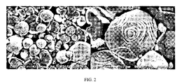
- Fig. 2 is an SEM image of the nickel oxide particles of Example 2. Scale bars are respectively 5.00 ⁇ m (left side) and 1.00 ⁇ m (right side) .
- Fig. 3 is an SEM image of the nickel oxide particles of Comparative Example 1.
- the scale bar is 5.00 ⁇ m.
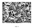
- Fig. 4 is an SEM image of the nickel oxide particles of Comparative Example 2.
- the scale bar is 5.00 ⁇ m.
- Fig. 5 is a graph illustrating measurement results of the nickel oxide particles of Examples and Comparative Examples by an X-ray diffraction method (XRD method) .
- the nickel oxide particles of the embodiment contain molybdenum.
- the nickel oxide particles of the embodiment contain molybdenum and have excellent properties such as catalytic activity derived from molybdenum.
- the molybdenum is preferably unevenly distributed in a surface layer of the nickel oxide particles.
- the “surface layer” in this specification means within 10 nm from a surface of the nickel oxide particles of the embodiment. This distance corresponds to a detection depth of XPS used for measurement in Examples.
- “unevenly distributed in the surface layer” means that a mass of molybdenum or the molybdenum compound per unit volume in the surface layer is greater than that of molybdenum or the molybdenum compound per unit volume other than the surface layer.
- the fact that molybdenum is unevenly distributed in the surface layer of the nickel oxide particles is confirmed by the fact that MoO 3 content (M 2 ) with respect to 100 mass%of the surface layer of the nickel oxide particles determined by XPS surface analysis of the nickel oxide particles is greater than MoO 3 content (M 1 ) with respect to 100 mass%of the surface layer of the nickel oxide particles determined by XRF (fluorescent X-ray) analysis of the nickel oxide particles as described in Examples described below.
- a surface layer uneven distribution ratio (M 2 /M 1 ) of the MoO 3 content (M 2 ) to the MoO 3 content (M 1 ) of the nickel oxide particles of the embodiment is preferably 0.05 or more and 1000.00 or less, more preferably 1.00 or more and 700.00 or less, and even more preferably 20.00 or more and 600.00 or less.
- the nickel oxide particles of the embodiment produced by a production method of the embodiment can have a unique granular (spherical) shape as described in Examples described below.
- a particle size and molybdenum content of nickel oxide particles obtained can be controlled by controlling a used amount and type of the molybdenum compound in the production method described below.
- a crystallite diameter of a [100] plane is preferably 240 nm or more, more preferably 250 nm or more, even more preferably 260 nm or more, and particularly preferably 290 nm or more.
- the crystallite diameter of the [100] plane may be 1000 nm or less, 900 nm or less, or 800 nm or less.
- a crystallite diameter of a [101] plane is preferably 220 nm or more, more preferably 250 nm or more, even more preferably 290 nm or more, and particularly preferably 310 nm or more.
- the crystallite diameter of the [101] plane may be 700 nm or less, 500 nm or less, or 400 nm or less.
- the nickel oxide particles of the embodiment having a crystallite diameter of the [100] plane of 240 nm or more and a crystallite diameter of the [101] plane of 220 nm or more can be exemplified.
- the nickel oxide particles can be more crystalline.
- a median diameter D 50 of the nickel oxide particles of the embodiment calculated by a laser diffraction/scattering method is preferably 10.00 ⁇ m or more and 1000.00 ⁇ m or less, more preferably 11.00 ⁇ m or more and 100.00 ⁇ m or less, even more preferably 12.00 ⁇ m or more and 70.00 ⁇ m or less, and particularly preferably 13.00 ⁇ m or more and 65.00 ⁇ m or less.
- the median diameter D 50 of the nickel oxide particles calculated by the laser diffraction/scattering method can be determined as a particle diameter in which a ratio of cumulative volume%is 50%in a particle diameter distribution measured by a dry method using a laser diffraction type particle size distribution meter.
- a particle diameter D 10 of the nickel oxide particles of the embodiment calculated by the laser diffraction/scattering method is preferably 3.00 ⁇ m or more and 100.00 ⁇ m or less, more preferably 5.00 ⁇ m or more and 50.00 ⁇ m or less, and even more preferably 6.00 ⁇ m or more and 40.00 ⁇ m or less.
- the particle diameter D 10 of the nickel oxide particles calculated by the laser diffraction/scattering method can be determined as a particle diameter in which the ratio of cumulative volume%from a small particle side is 10%in the particle diameter distribution measured by the dry method using the laser diffraction type particle size distribution meter.
- a particle diameter D 90 of the nickel oxide particles of the embodiment calculated by the laser diffraction/scattering method is preferably 13.00 ⁇ m or more and 1500.00 ⁇ m or less, more preferably 20.00 ⁇ m or more and 300.00 ⁇ m or less, and even more preferably 30.00 ⁇ m or more and 100.00 ⁇ m or less.
- the particle diameter D 90 of the nickel oxide particles calculated by the laser diffraction/scattering method can be determined as a particle diameter in which the ratio of cumulative volume%from the small particle side is 90%in the particle diameter distribution measured by the dry method using the laser diffraction type particle size distribution meter.
- the nickel oxide particles of the embodiment contain nickel oxide.
- Examples of nickel oxide that the nickel oxide particles of the embodiment may contain include NiO.
- Nickel oxide content in the nickel oxide particles can be measured by XRF analysis.
- NiO content N 1 with respect to 100 mass%of the nickel oxide particles determined by XRF analysis of the nickel oxide particles is preferably 60.00 mass%or more and 99.60 mass%or less, more preferably 90.00 mass%or more and 99.60 mass%or less, and even more preferably 95.00 mass%or more and 99.60 mass%or less.
- the nickel oxide particles of the embodiment contain molybdenum.
- MoO 3 content M 1 with respect to 100 mass%of the nickel oxide particles determined by XRF analysis of the nickel oxide particles is preferably 0.04 mass%or more and 40.00 mass%or less, more preferably 0.04 mass%or more and 20.00 mass%or less, even more preferably 0.04 mass%or more and 10.00 mass%or less, and particularly preferably 0.04 mass%or more and 1.50 mass%or less.
- the nickel oxide particles of the embodiment having the NiO content N 1 of 60.00 mass%or more and 99.60 mass%or less, and the MoO 3 content M 1 of 0.04 mass%or more and 40.00 mass%or less can be exemplified.
- NiO content N 1 and the MoO 3 content M 1 can be measured by XRF analysis, for example, using a fluorescent X-ray analyzer (PrimusIV) manufactured by Rigaku Corporation.
- NiO content N 2 with respect to 100 mass%of the surface layer of the nickel oxide particles determined by XPS surface analysis of the nickel oxide particles is preferably 10.00 mass%or more and 70.00 mass%or less, more preferably 30.00 mass%or more and 60.00 mass%or less, and even more preferably 50.00 mass%or more and 55.00 mass%or less.
- MoO 3 content M 2 with respect to 100 mass%of the surface layer of the nickel oxide particles determined by XPS surface analysis of the nickel oxide particles is preferably 2.00 mass%or more and 40.00 mass%or less, more preferably 10.00 mass%or more and 37.00 mass%or less, and even more preferably 25.00 mass%or more and 35.00 mass%or less.
- the nickel oxide particles of the embodiment having the NiO content N 2 of 10.00 mass%or more and 70.00 mass%or less, and the MoO 3 content M 2 of 20.00 mass%or more and 40.00 mass%or less can be exemplified.
- NiO content N 2 refers to a value determined as the content of NiO with respect to 100 mass%of the surface layer of the nickel oxide particles by obtaining an abundance ratio (atom%) for each element by XPS surface analysis of the nickel oxide particles by X-ray photoelectron spectroscopy (XPS) and by converting the nickel content to oxide.
- XPS X-ray photoelectron spectroscopy
- the above MoO 3 content M 2 refers to a value determined as the content of MoO 3 with respect to 100 mass%of the surface layer of the nickel oxide particles by obtaining an abundance ratio (atom%) for each element by XPS surface analysis of the nickel oxide particles by X-ray photoelectron spectroscopy (XPS) and by converting the molybdenum content to oxide.
- XPS X-ray photoelectron spectroscopy
- the nickel oxide particles of the embodiment may further contain lithium, potassium, or sodium in addition to molybdenum.
- the method for producing the nickel oxide particles of the embodiment includes a step of calcining a nickel compound in presence of the molybdenum compound. More specifically, the production method of the embodiment is the method for producing the nickel oxide particles, which may include mixing the nickel compound and the molybdenum compound to form a mixture, and calcining the mixture.
- the nickel oxide particles of the embodiment described above can be produced.
- a preferred method for producing the nickel oxide particles includes a step (mixing step) of mixing the nickel compound and the molybdenum compound to form the mixture, and a step (calcination step) of calcining the mixture.
- the mixing step is a step of mixing the nickel compound and the molybdenum compound to form the mixture.
- the contents of the mixture will be described below.
- the nickel compound is not limited as long as it is a compound that can be calcined to the nickel oxide.
- the nickel compound include the nickel oxide, nickel hydroxide, nickel oxyhydroxide, nickel sulfate, nickel nitrate, nickel carbonate and the like, and the nickel oxide is preferable.
- the nickel oxide may be NiO (nickel oxide (II) ) , Ni 2 O 3 (nickel oxide (III) ) , NiO 2 (nickel oxide (IV) ) , NiO, or nickel oxide containing one or more selected from a group including Ni 2 O 3 and NiO 2 .
- a shape of the nickel oxide particles after calcination hardly reflects a shape of a raw material nickel compound, any shape such as a sphere, an amorphous shape, a structure having an aspect (a wire, a fiber, a ribbon, a tube, or the like) , or a sheet can be suitably used as the nickel compound.
- Examples of the molybdenum compound include molybdenum oxide and molybdate compounds.
- Examples of the molybdenum oxide include molybdenum dioxide and molybdenum trioxide, and the molybdenum trioxide is preferable.
- the molybdate compound is not limited as long as it is a salt compound of molybdenum oxoanion such as MoO 4 2- , Mo 2 O 7 2- , Mo 3 O 10 2- , Mo 4 O 13 2- , Mo 5 O 16 2- , Mo 6 O 19 2- , Mo 7 O 24 6- , or Mo 8 O 26 4- . It may be an alkali metal salt of the molybdenum oxoanion, an alkaline earth metal salt, or an ammonium salt.
- the alkali metal salt of the molybdenum oxoanion is preferable, lithium molybdate, potassium molybdate or sodium molybdate is more preferable, and potassium molybdate or sodium molybdate is further preferable.
- the molybdate compound may be a hydrate.
- the molybdate compound is preferably at least one compound selected from a group including molybdenum trioxide, lithium molybdate, potassium molybdate, and sodium molybdate, and more preferably at least one compound selected from a group including molybdenum trioxide, potassium molybdate, and sodium molybdate.
- the production method of the embodiment may include a step of calcining the nickel compound in the presence of the molybdenum compound and a potassium compound.
- the production method of the embodiment can include the step (mixing step) of mixing the nickel compound, the molybdenum compound, and the potassium compound to form the mixture prior to the calcination step, and can include the step (calcination step) of calcining the mixture.
- the production method of the embodiment can include the step (mixing step) of mixing the nickel compound and a compound containing molybdenum and potassium to form the mixture prior to the calcination step, and can include the step (calcination step) of calcining the mixture.
- the compound containing molybdenum and potassium which is suitable as a flux agent, can be produced, for example, using a molybdenum compound and a potassium compound, which are cheaper and more easily available, as raw materials in the calcination step.
- a molybdenum compound and a potassium compound which are cheaper and more easily available, as raw materials in the calcination step.
- both when the molybdenum compound and the potassium compound are used as the flux agent and when the compound containing molybdenum and potassium is used as the flux agent are combined and regarded as when the molybdenum compound and the potassium compound are used as the flux agent, that is, in the presence of the molybdenum compound and the potassium compound.
- the production method of the embodiment may include a step of calcining the nickel compound in the presence of the molybdenum compound and a sodium compound.
- the production method of the embodiment can include a step (mixing step) of mixing the nickel compound, the molybdenum compound, and the sodium compound to form the mixture prior to the calcination step, and can include a step (calcination step) of calcining the mixture.
- the production method of the embodiment can include a step (mixing step) of mixing the nickel compound and a compound containing molybdenum and sodium to form the mixture prior to the calcination step, and can include a step (calcination step) of calcining the mixture.
- the compound containing molybdenum and sodium which is suitable as the flux agent, can be produced, for example, using the molybdenum compound and the sodium compound, which are cheaper and more easily available, as raw materials in the calcination step.
- both when the molybdenum compound and the sodium compound are used as the flux agent and when the compound containing molybdenum and sodium is used as the flux agent are combined and regarded as when the molybdenum compound and the sodium compound are used as the flux agent, that is, in the presence of the molybdenum compound and the sodium compound.
- the nickel oxide particles having a high molybdenum content can be easily obtained, and the particle diameter of the nickel oxide particles produced can be easily adjusted.
- the reason is not clear, but the following reasons can be considered.
- K 2 MoO 4 and Na 2 MoO 4 are stable compounds and are difficult to volatilize in the calcination step, they are unlikely to be accompanied by a rapid reaction in a volatilization step, and growth of the nickel oxide particles can be easily controlled.
- the molten K 2 MoO 4 and Na 2 MoO 4 exert a function like a solvent, and for example, by increasing a reaction time, a value of the particle diameter can be increased.
- the molybdenum compound is used as the flux agent.
- the production method using the molybdenum compound as the flux agent may be simply referred to as the “flux method” . Note that after the molybdenum compound reacts with the nickel compound at a high temperature to form nickel molybdate by such calcination, when the nickel molybdate is further decomposed into nickel and molybdenum oxide at a higher temperature, it is considered that the molybdenum compound is incorporated into the nickel oxide particles.
- the molybdenum oxide is sublimated and removed from the system, and in this step, the molybdenum compound and the nickel compound react to form the molybdenum compound in the surface layer of the nickel oxide particles.
- the molybdenum compound contained in the nickel oxide particles more specifically, it is considered that Mo-O-Ni is formed in the surface layer of the nickel oxide particles by reaction of molybdenum and Ni atoms, Mo is desorbed by high-temperature calcination, and the molybdenum oxide, a compound having a Mo-O-Ni bond, or the like is formed in the surface layer of the nickel oxide particles.
- the molybdenum oxide that is not incorporated into the nickel oxide particles can also be recovered by sublimation and reused. In this way, an amount of the molybdenum oxide adhering to the surface of the nickel oxide particles can be reduced, and original properties of the nickel oxide particles can be maximized.
- the alkali metal salt of the molybdenum oxoanion does not vaporize even in a calcination temperature range and can be easily recovered by washing after calcination, so that an amount of the molybdenum compound released to outside a calcining furnace is also reduced, and production cost can also be significantly reduced.
- the molybdenum compound and the potassium compound when used in combination, it is considered that the molybdenum compound and the potassium compound first react to form the potassium molybdate. At the same time, it is considered that the molybdenum compound reacts with the nickel compound to form the nickel molybdate. Then, for example, the nickel molybdate is decomposed in the presence of potassium molybdate in a liquid phase to grow crystals, so that the nickel oxide particles having a large particle size and a high molybdenum content can be easily obtained while suppressing evaporation of flux (sublimation of MoO 3 ) described above.
- a metal compound can be used at a time of calcination if desired.
- the production method of the embodiment can include a step (mixing step) of mixing the nickel compound, the molybdenum compound, the potassium compound, and the metal compound to form the mixture prior to the calcination step, and can include a step (calcination step) of calcining the mixture.
- the metal compound is not particularly limited, but preferably contains at least one selected from a group including Group II metal compounds and Group III metal compounds.
- Group II metal compounds examples include magnesium compounds, calcium compounds, strontium compounds, barium compounds and the like.
- Group III metal compounds examples include scandium compounds, yttrium compounds, lanthanum compounds, cerium compounds and the like.
- the above-mentioned metal compound means an oxide, a hydroxide, a carbonate, or a chloride of a metal element.
- a metal element for example, in the case of the yttrium compound, yttrium oxide (Y 2 O 3 ) , yttrium hydroxide, and yttrium carbonate can be mentioned.
- the metal compound is preferably an oxide of the metal element. Note that the metal compound contains an isomer.
- the metal compound of period 3 element, the metal compound of period 4 element, the metal compound of period 5 element, and the metal compound of period 6 element are preferable, the metal compound of the 4th period element and the metal compound of period 5 element are more preferable, and the metal compound of period 5 element is further preferable.
- the magnesium compound, the calcium compound, the yttrium compound, and the lanthanum compound are preferably used, the magnesium compound, the calcium compound, and the yttrium compound are more preferably used, and the yttrium compound is particularly preferably used.
- the metal compound is preferably used in a proportion of, for example, 0.0 mass%or more and 1.2 mass%or less (for example, 0 mol%or more and 1 mol%or less) with respect to a total amount (total mass or total molar amount) of the nickel compounds used in the mixing step.
- blending amounts of the nickel compound and the molybdenum compound are not particularly limited, but preferably 35 mass%or more of the nickel compound and 65 mass%or less of the molybdenum compound are mixed with respect to 100 mass%of the mixture to form the mixture, and the mixture can be calcined. More preferably, 40 mass%or more and 90 mass%or less of the nickel compound and 0.5 mass%or more and 60 mass%or less of the molybdenum compound are mixed with respect to 100 mass%of the mixture to form the mixture, and the mixture can be calcined.
- a value of a molar ratio (molybdenum/nickel) of molybdenum atom in the molybdenum compound and nickel atom in the nickel compound is preferably 0.01 or more, more preferably 0.05 or more, even more preferably 0.10 or more, and particularly preferably 0.30 or more.
- An upper limit value of the molar ratio of the molybdenum atom in the molybdenum compound and the nickel atom in the nickel compound may be appropriately determined, but from a viewpoint of reducing the amount of molybdenum compound used and improving production efficiency, for example, the value of the above molar ratio (molybdenum/nickel) may be 5.00 or less, 3.00 or less, 1.00 or less, or 0.50 or less.
- the value of molybdenum/nickel may be 0.01 or more and 5.00 or less, 0.05 or more and 3.00 or less, 0.10 or more and 1.00 or less, and 0.30 or more and 0.50 or less.
- the amount of the molybdenum compound contained in the nickel oxide particles obtained becomes more appropriate, and the nickel oxide particles having a controlled particle size can be easily obtained.
- the calcination step is a step of calcining the mixture.
- the nickel oxide particles according to the embodiment can be obtained by calcining the mixture.
- the production method is called the flux method.
- the flux method is classified as a solution method. More specifically, the flux method is a method of crystal growth utilizing the fact that a crystal-flux two-component phase diagram shows a eutectic type.
- a mechanism of the flux method is presumed to be as follows. That is, when a mixture of solute and the flux is heated, the solute and the flux become a liquid phase. At this time, since the flux is a fusing agent, in other words, since a solute-flux two-component phase diagram shows a eutectic type, the solute melts at a temperature lower than its melting point to form the liquid phase.
- concentration of the flux is reduced, in other words, an effect on lowering the melting point of the solute by the flux is reduced, and the evaporation of the flux acts as a driving force to cause crystal growth of the solute (flux evaporation method) .
- the solute and the flux can also cause the crystal growth of the solute by cooling the liquid phase (slow cooling method) .
- the flux method has merits such as being able to grow the crystals at a temperature much lower than the melting point, being able to precisely control a crystal structure, and being able to form a polyhedral crystal having an automorphic shape.
- the mechanism In production of the nickel oxide particles by the flux method using the molybdenum compound as the flux, the mechanism is not always clear, but for example, it is presumed that the mechanism is as follows. That is, when the nickel compound is calcined in the presence of the molybdenum compound, the nickel molybdate is first formed. At this time, as can be understood from the above description, the nickel molybdate grows nickel oxide crystals at a temperature lower than the melting point of the nickel oxide. Then, for example, by evaporating the flux, the nickel molybdate is decomposed to grow the crystals, so that the nickel oxide particles can be obtained. That is, the molybdenum compound functions as the flux, and the nickel oxide particles are produced via an intermediate called the nickel molybdate.
- the nickel oxide particles containing molybdenum and in which the molybdenum is unevenly distributed in the surface layer of the nickel oxide particles can be produced.
- a method of calcination is not particularly limited, and the calcination can be performed by a known and commonly used method.
- the calcination temperature exceeds 800°C, it is considered that the nickel compound and the molybdenum compound react to form the nickel molybdate. Further, it is considered that when the calcination temperature becomes 950°C or higher, the nickel molybdate is decomposed to form the nickel oxide particles. Further, in the nickel oxide particles, it is considered that the molybdenum compound is incorporated into the nickel oxide particles when the nickel molybdate is decomposed into the nickel oxide and the molybdenum oxide.
- a state of the nickel compound and the molybdenum compound at the time of calcination is not particularly limited, and the molybdenum compound may be present in the same space where the molybdenum compound can act on the nickel compound.
- the state may be a simple mixture in which powders of the molybdenum compound and powders of the nickel compound are mixed, a mechanical mixture using a crusher or the like, a mixture using a mortar or the like, and may be a mixture in a dry state or in a wet state.
- Conditions of the calcination temperature are not particularly limited, and are appropriately determined in consideration of a target particle size of the nickel oxide particles, formation of the molybdenum compound in the nickel oxide particles, the shape of the nickel oxide particles, and the like.
- the calcination temperature may be 900°C or higher, which is close to a decomposition temperature of the nickel molybdate, 950°C or higher, or 1000°C or higher.
- the calcination temperature is higher, the nickel oxide particles having a controlled particle shape and a large particle size tend to be easily obtained. From a viewpoint of efficiently producing such nickel oxide particles, the calcination temperature is preferably 950°C or higher, more preferably 1000°C or higher, even more preferably 1100°C or higher, and particularly preferably 1200°C or higher.
- the nickel oxide particles can be efficiently formed at low cost.
- the nickel oxide particles having an automorphic shape can be formed regardless of a shape of a precursor.
- the calcination temperature is preferably 1500°C or lower, more preferably 1400°C or lower, and even more preferably 1300°C or lower.
- a numerical range of the calcination temperature at which the nickel compound is calcined in the calcination step may be 900°C or higher and 1600°C or lower, 900°C or higher and 1500°C or lower, 950°C or higher and 1400°C or lower, 1000°C or higher and 1300°C or lower, or 1100°C or higher and 1300°C or lower.
- a heating rate may be 20°C/hour or more and 600°C/hour or less, 40°C/hour or more and 500°C/hour or less, and 80°C/hour or more and 400°C/hour or less.
- the calcination is preferably performed such that a raising time to a predetermined calcination temperature is in a range of 15 minutes or more and 10 hours or less, and a holding time at the calcination temperature is in a range of 5 minutes or more and 30 hours or less.
- the holding time at the calcination temperature is 2 hours or more and 24 hours or less.
- the nickel oxide particles of the embodiment containing molybdenum can be easily obtained.
- Calcination atmosphere is not particularly limited as long as an effect of the production method of the embodiment can be obtained, but for example, oxygen-containing atmosphere such as air or oxygen or an inert atmosphere such as nitrogen, argon or carbon dioxide is preferable, and air atmosphere is more preferable when considering the cost.
- oxygen-containing atmosphere such as air or oxygen
- an inert atmosphere such as nitrogen, argon or carbon dioxide
- air atmosphere is more preferable when considering the cost.
- An apparatus for calcination is also not necessarily limited, and a so-called calcining furnace can be used.
- the calcining furnace is preferably made of a material that does not react with sublimated molybdenum oxide, and it is preferable to use a highly airtight calcining furnace so that the molybdenum oxide can be used efficiently.
- the production method of the embodiment may further include a molybdenum removal step of removing at least a part of molybdenum after the calcination step, if necessary.
- the molybdenum is sublimated during calcination, it is possible to control the molybdenum content present in the surface layer of the nickel oxide particles, and to control the molybdenum content and its existence state in other than the surface layer (inner layer) of the nickel oxide particles, by controlling the calcination time, the calcination temperature, and the like.
- the molybdenum can adhere to the surface of the nickel oxide particles.
- the molybdenum can be removed by washing with water, an aqueous ammonia solution, an aqueous sodium hydroxide solution or the like.
- the molybdenum content in the nickel oxide particles can be controlled by appropriately changing concentration and used amount of the water, the aqueous ammonia solution, or the aqueous sodium hydroxide solution used, and a washing site, a washing time or the like.
- the nickel oxide particles may aggregate, and the calcined product may not meet a range of particle diameter suitable for applications to be considered. Therefore, the nickel oxide particles may be pulverized to satisfy the range of suitable particle diameter, if necessary.
- a method for pulverizing the calcined product is not particularly limited, and conventionally known pulverizing methods such as ball mill, jaw crusher, jet mill, disc mill, Spectromill, grinder, and mixer mill can be used.
- the calcined product containing the nickel oxide particles obtained in the calcination step may be appropriately classified in order to adjust a range of the particle size.
- a “classification process” refers to an operation of grouping particles based on the size of the particles.
- the classification may be either wet or dry, but from a viewpoint of productivity, the dry classification is preferable.
- the dry classification includes classification by sieving, wind classification by a difference between centrifugal force and fluid drag, and the like, but from a viewpoint of classification accuracy, the wind classification is preferable, and can be performed by using a classifier using Coanda effect, such as an airflow classifier, a swirling airflow classifier, a forced vortex centrifugal classifier, and a semi-free vortex centrifugal classifier.
- the above-mentioned pulverization step and classification step can be performed at a necessary stage.
- the average particle diameter of the nickel oxide particles to be obtained can be adjusted by the presence or absence of pulverizing and classification, and selection of their conditions.
- the nickel oxide particles of the embodiment or the nickel oxide particles obtained by the production method of the embodiment are likely to exhibit their original properties and are superior in their own handleability, and when they are used by being dispersed in a medium to be dispersed, they are preferable from the viewpoint of being more excellent in dispersibility.
- the nickel oxide particles having little or no aggregation can be easily produced, it has an excellent advantage that the nickel oxide particles having excellent desired properties can be produced with high productivity without performing the above-mentioned pulverization step or classification step.
- the nickel oxide particles of the embodiment or the nickel oxide particles obtained by the production method of the embodiment have the above-mentioned characteristics, they are preferably used, for example, for an electrode of a solid oxide fuel cell (SOFC) or an electrode of a steam charge device, or the like.
- SOFC solid oxide fuel cell
- Nickel oxide produced by Aladdin was used as it was as a sample of Comparative Example 3.
- Scan range: from 10° to 70°
- Apparatus standard width 0.026° calculated using standard silicon powder (NIST, 640d) produced by the National Institute of Standards and Technology was used.
- the sample powders were filled in a holder for a measurement sample having a depth of 0.5 mm, set in a wide-angle X-ray diffraction (XRD) apparatus (Ultima IV manufactured by Rigaku Corporation) , and the measurement was performed under conditions of Cu/K ⁇ ray, 40 kV/40 mA, scanning speed 2°/min, and scanning range of 10° to 70°.
- XRD X-ray diffraction
- the particle size distribution of the sample powders was measured by the dry method under conditions of a dispersion pressure of 3 bar and a pulling pressure of 90 mbar.
- the particle diameter at a point where a distribution curve of cumulative volume%intersects a horizontal axis of 10%from the small particle side was defined as D 10
- the particle diameter at a point where the distribution curve intersects the horizontal axis of 50% was defined as D 50
- the particle diameter at a point where the distribution curve intersects the horizontal axis of 90%from the small particle side was defined as D 90 , and they were determined.
- NiO content (N 1 ) with respect to 100 mass%of the nickel oxide particles and the MoO 3 content (M 1 ) with respect to 100 mass%of the nickel oxide particles were obtained by XRF analysis.
- XPS X-ray Photoelectron spectroscopy
- the NiO content (N 2 ) (mass%) with respect to 100 mass%of the surface layer of the nickel oxide particles and the MoO 3 content (M 2 ) (mass%) with respect to 100 mass%of the surface layer of the nickel oxide particles were determined.
- Table 1 shows each value obtained by the above evaluation. Note that “N. D. ” is an abbreviation for not detected, and indicates that it is not detected.
- the nickel oxide particles of Examples 1 and 2 contain molybdenum on the surface, and it is expected that various actions of molybdenum, such as catalytic activity will be exerted.
- the nickel oxide particles and the method for producing the nickel oxide particles of the embodiment the nickel oxide particles having a controlled particle diameter and particle size distribution can be obtained.
Landscapes
- Chemical & Material Sciences (AREA)
- Organic Chemistry (AREA)
- Chemical Kinetics & Catalysis (AREA)
- Engineering & Computer Science (AREA)
- Materials Engineering (AREA)
- Electrochemistry (AREA)
- General Chemical & Material Sciences (AREA)
- Inorganic Chemistry (AREA)
- Composite Materials (AREA)
- Physics & Mathematics (AREA)
- Thermal Sciences (AREA)
- Inorganic Compounds Of Heavy Metals (AREA)
Abstract
Description
Table 1 shows each value obtained by the above evaluation. Note that “N. D. ” is an abbreviation for not detected, and indicates that it is not detected.

Each configuration in each embodiment, a combination thereof, and the like are examples, and the configuration can be added, omitted, replaced, and other changes can be made without departing from the spirit of the present application. Further, the present invention is not limited by each embodiment, but is limited only by the scope of the claims.
Claims (11)
- Nickel oxide particles comprising molybdenum.
- The nickel oxide particles according to claim 1, wherein the molybdenum is unevenly distributed in a surface layer of the nickel oxide particles.
- The nickel oxide particles according to claim 1 or 2, wherein a crystallite diameter of a [100] plane of the nickel oxide particles is 240 nm or more.
- The nickel oxide particles according to any one of claims 1 to 3, wherein a crystallite diameter of a [101] plane of the nickel oxide particles is 220 nm or more.
- The nickel oxide particles according to any one of claims 1 to 4, wherein a median diameter D 50 of the nickel oxide particles calculated by a laser diffraction/scattering method is 10.00 μm or more and 1000.00 μm or less.
- The nickel oxide particles according to any one of claims 1 to 5, whereinNiO content N 1 with respect to 100 mass%of the nickel oxide particles determined by XRF analysis of the nickel oxide particles is 60.00 mass%or more and 99.60 mass%or less, andMoO 3 content M 1 with respect to 100 mass%of the nickel oxide particles determined by XRF analysis of the nickel oxide particles is 0.04 mass%or more and 40.00 mass%or less.
- The nickel oxide particles according to any one of claims 1 to 6, whereinNiO content N 2 with respect to 100 mass%of a surface layer of the nickel oxide particles determined by XPS surface analysis of the nickel oxide particles is 10.00 mass%or more and 70.00 mass%or less, andMoO 3 content M 2 with respect to 100 mass%of the surface layer of the nickel oxide particles determined by XPS surface analysis of the nickel oxide particles is 20.00 mass%or more and 40.00 mass%or less.
- The nickel oxide particles according to any one of claims 1 to 7, wherein a surface layer uneven distribution ratio M 2/M 1 of MoO 3 content M 2 with respect to 100 mass%of a surface layer of the nickel oxide particles determined by XPS surface analysis of the nickel oxide particles to MoO 3 content M 1 with respect to 100 mass%of the nickel oxide particles determined by XRF analysis of the nickel oxide particles is 0.05 or more and 1000.00 or less.
- A method for producing the nickel oxide particles according to any one of claims 1 to 8, comprising calcining a nickel compound in presence of a molybdenum compound.
- The method for producing the nickel oxide particles according to claim 9, wherein the molybdenum compound is at least one compound selected from a group including molybdenum trioxide, lithium molybdate, potassium molybdate and sodium molybdate.
- The method for producing the nickel oxide particles according to claim 9 or 10, wherein a calcination temperature is 800℃ or higher and 1600℃ or lower.
Priority Applications (4)
| Application Number | Priority Date | Filing Date | Title |
|---|---|---|---|
| US18/562,834 US20240243301A1 (en) | 2021-05-27 | 2021-05-27 | Nickel oxide particles and method for producing the same |
| PCT/CN2021/096527 WO2022246765A1 (en) | 2021-05-27 | 2021-05-27 | Nickel oxide particles and method for producing the same |
| CN202180098596.1A CN117397070A (en) | 2021-05-27 | 2021-05-27 | Nickel oxide particles and method for producing nickel oxide particles |
| JP2023572690A JP2024518653A (en) | 2021-05-27 | 2021-05-27 | Nickel oxide particles and method for producing same |
Applications Claiming Priority (1)
| Application Number | Priority Date | Filing Date | Title |
|---|---|---|---|
| PCT/CN2021/096527 WO2022246765A1 (en) | 2021-05-27 | 2021-05-27 | Nickel oxide particles and method for producing the same |
Publications (1)
| Publication Number | Publication Date |
|---|---|
| WO2022246765A1 true WO2022246765A1 (en) | 2022-12-01 |
Family
ID=84229444
Family Applications (1)
| Application Number | Title | Priority Date | Filing Date |
|---|---|---|---|
| PCT/CN2021/096527 WO2022246765A1 (en) | 2021-05-27 | 2021-05-27 | Nickel oxide particles and method for producing the same |
Country Status (4)
| Country | Link |
|---|---|
| US (1) | US20240243301A1 (en) |
| JP (1) | JP2024518653A (en) |
| CN (1) | CN117397070A (en) |
| WO (1) | WO2022246765A1 (en) |
Citations (4)
| Publication number | Priority date | Publication date | Assignee | Title |
|---|---|---|---|---|
| US3972954A (en) * | 1972-02-14 | 1976-08-03 | Phillips Petroleum Company | Process for oxidative dehydrogenation |
| US20130105364A1 (en) * | 2011-10-27 | 2013-05-02 | Shell Oil Company | Low cost and high activity hydroprocessing catalyst |
| US20130284640A1 (en) * | 2012-04-26 | 2013-10-31 | Shell Oil Company | Hydroprocessing catalyst and process for treating heavy hydrocarbon feedstocks |
| CN106159288A (en) * | 2015-04-22 | 2016-11-23 | 中国科学院物理研究所 | A kind of anti-carbon Ni base anode material, preparation method and purposes |
-
2021
- 2021-05-27 WO PCT/CN2021/096527 patent/WO2022246765A1/en active Application Filing
- 2021-05-27 CN CN202180098596.1A patent/CN117397070A/en active Pending
- 2021-05-27 JP JP2023572690A patent/JP2024518653A/en active Pending
- 2021-05-27 US US18/562,834 patent/US20240243301A1/en active Pending
Patent Citations (4)
| Publication number | Priority date | Publication date | Assignee | Title |
|---|---|---|---|---|
| US3972954A (en) * | 1972-02-14 | 1976-08-03 | Phillips Petroleum Company | Process for oxidative dehydrogenation |
| US20130105364A1 (en) * | 2011-10-27 | 2013-05-02 | Shell Oil Company | Low cost and high activity hydroprocessing catalyst |
| US20130284640A1 (en) * | 2012-04-26 | 2013-10-31 | Shell Oil Company | Hydroprocessing catalyst and process for treating heavy hydrocarbon feedstocks |
| CN106159288A (en) * | 2015-04-22 | 2016-11-23 | 中国科学院物理研究所 | A kind of anti-carbon Ni base anode material, preparation method and purposes |
Also Published As
| Publication number | Publication date |
|---|---|
| CN117397070A (en) | 2024-01-12 |
| JP2024518653A (en) | 2024-05-01 |
| US20240243301A1 (en) | 2024-07-18 |
Similar Documents
| Publication | Publication Date | Title |
|---|---|---|
| KR102611412B1 (en) | Method for producing zirconium tungstate phosphate | |
| TWI750137B (en) | Method for manufacturing zirconium tungstate phosphate | |
| CN112566872B (en) | Plate-shaped alumina particles and method for producing plate-shaped alumina particles | |
| WO2022246765A1 (en) | Nickel oxide particles and method for producing the same | |
| WO2020026971A1 (en) | Garnet-type composite metal oxide and method for producing same | |
| US20240262705A1 (en) | Ceria particles and method for producing the same | |
| WO2022257149A1 (en) | Gallia particles and method for producing gallia particles | |
| WO2022257148A1 (en) | Gadolinia particles and method for producing gadolinia particles | |
| WO2022126435A9 (en) | Zirconia particles and method for producing zirconia particles | |
| WO2022120528A1 (en) | Tantalum oxide particle and method for producing tantalum oxide particle | |
| WO2023201620A1 (en) | Tantalate particles and method for producing tantalate particles | |
| WO2023206226A1 (en) | Forsterite particles and method for producing forsterite particles | |
| WO2024020979A1 (en) | Ferrite particles and method for producing ferrite particles | |
| WO2023204273A1 (en) | Niobate particles and method for manufacturing niobate particles | |
| WO2022120620A1 (en) | Iron oxide particles and method for producing iron oxide particles | |
| KR20230116777A (en) | Niobium oxide particles and method for producing niobium oxide particles |
Legal Events
| Date | Code | Title | Description |
|---|---|---|---|
| 121 | Ep: the epo has been informed by wipo that ep was designated in this application |
Ref document number: 21942341 Country of ref document: EP Kind code of ref document: A1 |
|
| WWE | Wipo information: entry into national phase |
Ref document number: 18562834 Country of ref document: US |
|
| WWE | Wipo information: entry into national phase |
Ref document number: 202180098596.1 Country of ref document: CN Ref document number: 2023572690 Country of ref document: JP |
|
| NENP | Non-entry into the national phase |
Ref country code: DE |
|
| 122 | Ep: pct application non-entry in european phase |
Ref document number: 21942341 Country of ref document: EP Kind code of ref document: A1 |