WO2022244262A1 - ネットワーク遅延測定システム、ネットワーク遅延測定方法及びネットワーク遅延測定装置 - Google Patents
ネットワーク遅延測定システム、ネットワーク遅延測定方法及びネットワーク遅延測定装置 Download PDFInfo
- Publication number
- WO2022244262A1 WO2022244262A1 PCT/JP2021/019438 JP2021019438W WO2022244262A1 WO 2022244262 A1 WO2022244262 A1 WO 2022244262A1 JP 2021019438 W JP2021019438 W JP 2021019438W WO 2022244262 A1 WO2022244262 A1 WO 2022244262A1
- Authority
- WO
- WIPO (PCT)
- Prior art keywords
- measurement
- packet
- delay
- circuit
- response
- Prior art date
- Legal status (The legal status is an assumption and is not a legal conclusion. Google has not performed a legal analysis and makes no representation as to the accuracy of the status listed.)
- Ceased
Links
Images



Classifications
-
- H—ELECTRICITY
- H04—ELECTRIC COMMUNICATION TECHNIQUE
- H04L—TRANSMISSION OF DIGITAL INFORMATION, e.g. TELEGRAPHIC COMMUNICATION
- H04L43/00—Arrangements for monitoring or testing data switching networks
- H04L43/08—Monitoring or testing based on specific metrics, e.g. QoS, energy consumption or environmental parameters
- H04L43/0852—Delays
-
- H—ELECTRICITY
- H04—ELECTRIC COMMUNICATION TECHNIQUE
- H04L—TRANSMISSION OF DIGITAL INFORMATION, e.g. TELEGRAPHIC COMMUNICATION
- H04L43/00—Arrangements for monitoring or testing data switching networks
- H04L43/08—Monitoring or testing based on specific metrics, e.g. QoS, energy consumption or environmental parameters
- H04L43/0852—Delays
- H04L43/0864—Round trip delays
Definitions
- the present invention relates to a network delay measurement system, a network delay measurement method, and a network delay measurement device.
- Non-Patent Document 1 ICMP (Internet Control Message Protocol) is known.
- the ICMP protocol is used to confirm the state of communication between computers that implement TCP/IP.
- Ping is known as a network diagnostic program that uses the ICMP protocol. Ping measures the time from sending an "echo request" ICMP packet to receiving an "echo reply” ICMP packet as a round trip delay time. Ping is to measure the round-trip delay time between two nodes on the network (1:1 configuration of delay measuring device and opposite terminal).
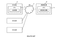
- a delay measuring device 70 is connected to an opposite terminal 72 via a computer network 71 .
- Ping is implemented by software, and delay measurement processing is calculated on the CPUs 73 and 74 .
- the CPUs 73 and 74 are general-purpose processors, and may be required to perform calculations of other functions implemented by software while performing calculations for delay measurement processing. In that case, the delay measurement process is suspended depending on the priority of the calculation. This is called interrupt processing.
- the delay measurement process suspends calculation due to interrupt processing of other functions, there is the problem that the delay time cannot be measured accurately. Further, the calculation by the CPUs 73 and 74, which are general-purpose processors, does not necessarily have sufficient calculation speed and information transmission speed, and the time required to calculate the delay time is not sufficiently short. As the need for high-speed, large-capacity communication increases, high-speed, high-precision delay measurement technology is required as an information processing platform. High-speed, high-precision delay measurement is expected to be used for network control (route changes, etc.) by understanding delay fluctuations that occur within a network.
- a network delay measurement system includes a delay measurement device and a remote terminal.
- the delay measurement device includes a general-purpose processor that operates according to a loaded program, and a delay measurement dedicated circuit that has a lower latency than the general-purpose processor, does not use the program, and operates according to a pre-installed circuit.
- the correspondent terminal communicates with the delay measuring device via a computer network.
- the delay measurement dedicated circuit includes a measurement packet generation section, a response packet reception section, and a delay time calculation section, which are pre-installed.
- the measurement packet generator generates a measurement packet, transmits the measurement packet to the remote terminal, and stores the transmission time of the measurement packet.
- the response packet receiving unit receives a response packet from the opposite terminal and stores the reception time of the response packet.
- the delay time calculator calculates a round trip delay time by subtracting the transmission time from the reception time.
- the opposite terminal has a pre-installed dedicated response circuit. The response dedicated circuit transmits the response packet when the measurement packet is received.
- a second aspect relates to a network delay measuring method using a delay measuring device and a correspondent terminal.
- the delay measurement device includes a general-purpose processor that operates according to a loaded program, and a delay measurement dedicated circuit that has a lower latency than the general-purpose processor, does not use the program, and operates according to a pre-installed circuit.
- the opposite terminal communicates with the delay measurer via a computer network and includes response-only circuitry that operates according to pre-installed circuitry.
- the network delay measurement method includes a measurement packet generation step, a response packet transmission step, a response packet reception step, and a delay time calculation step.
- the measurement packet generation step uses the delay measurement dedicated circuit to generate a measurement packet, transmits the measurement packet to the opposite terminal, and stores the transmission time of the measurement packet.
- the response packet transmission step transmits a response packet using the response dedicated circuit when the opposite terminal receives the measurement packet.
- the response packet receiving step uses the delay measurement dedicated circuit to receive the response packet from the opposite terminal and store the reception time of the response packet.
- the delay time calculating step calculates a round-trip delay time by subtracting the transmission time from the reception time using the general-purpose processor or the delay measurement dedicated circuit.
- a third aspect relates to a network delay measurement device.
- a network delay measurement device is a delay measurement device that communicates with an opposite terminal via a computer network.
- the network delay measurement device includes a general-purpose processor that operates according to a loaded program, and a delay measurement dedicated circuit that has a lower latency than the general-purpose processor and operates according to a pre-installed circuit without using the program.
- the delay measurement dedicated circuit includes a measurement packet generation section, a response packet reception section, and a delay time calculation section, which are pre-installed.
- the measurement packet generator generates a measurement packet, transmits the measurement packet to the remote terminal, and stores the transmission time of the measurement packet.
- the response packet receiving unit receives a response packet from the opposite terminal and stores the reception time of the response packet.
- the delay time calculator calculates a round trip delay time by subtracting the transmission time from the reception time.
- a fourth aspect relates to a network delay measurement device.
- a network delay measurement device is an opposite terminal that communicates with a delay measurement device via a computer network.
- the network delay measurement device comprises a response-only circuit operating according to a pre-installed circuit, a buffer, and a bifurcation circuit for transmitting received measurement packets to the response-only circuit and the buffer, respectively.
- the response dedicated circuit receives the measurement packet from the bifurcation circuit without going through the buffer, and transmits the response packet.
- a delay measurement dedicated circuit and a response dedicated circuit built in advance generate a delay measurement packet and a response packet, and software processing is not required. Therefore, according to the present invention, high-speed and highly accurate delay measurement is possible without being affected by interrupt processing. According to such a technique, it is possible to grasp delay fluctuations that occur in the network and utilize them for network control (route change, etc.).
- FIG. 1 is a conceptual diagram for explaining an overview of a network delay measurement system according to Embodiment 1 of the present invention
- FIG. 1 is a conceptual diagram for explaining an outline of a network delay measuring device according to Embodiment 1 of the present invention
- FIG. 3 is a block diagram illustrating a configuration of the delay measuring device according to Embodiment 1 of the present invention
- FIG. 3 is a block diagram illustrating the configuration of the opposite terminal according to Embodiment 1 of the present invention
- FIG. 3 is a block diagram illustrating the configuration of the opposite terminal according to Embodiment 1 of the present invention
- FIG. 2 is a conceptual diagram for explaining an overview of a network delay measurement system according to Embodiment 2 of the present invention
- FIG. 10 is a diagram for explaining a problem of delay measurement processing implemented by software;
- FIG. 1 is a conceptual diagram for explaining an outline of a network delay measurement system according to the first embodiment.
- a network delay measurement system 1 shown in FIG. 1 as the opposed terminals 4, a first opposed terminal 4a, a second opposed terminal 4b, and a third opposed terminal 4c are illustrated.
- the delay measuring device 2 and the correspondent terminal 4 function as network delay measuring devices.
- the delay measuring device 2 is connected to each opposing terminal 4 via a branching device 5 and a computer network 3.
- the delay measuring device 2 is a device having a function of measuring the delay time with the opposite terminal 4 .
- the opposite terminal 4 is a device whose delay time is to be measured.
- the opposite terminal 4 is a device having a function of transmitting a response signal (response packet) in response to a request signal (delay measurement packet) from the delay measuring device 2 .
- the opposite terminal 4 may be a user end terminal such as a personal computer, or a terminal on a network such as an ONU (Optical Network Unit). Also, the number of the opposed terminals 4 may be one, or may be plural.
- the computer network 3 is a wired or wireless network, and the type and scale of the network do not matter.
- computer network 3 is an optical network.
- the splitter 5 is a device for networking the delay measuring device 2 and the opposite terminal 4 .
- the splitter 5 is, for example, an optical switch or an optical coupler in an optical network.
- FIG. 2 is a diagram for explaining the outline of the network delay measuring device according to the first embodiment.
- the delay measuring device 2 and the correspondent terminal 4 have a 1:1 configuration, but they may have a 1:n configuration.
- the delay measuring instrument 2 has a memory (not shown), a CPU 21 and a hardware processing section 22 .
- the opposed terminal 4 has a memory (not shown), a CPU 41 and a hardware processing section 42 .
- the CPUs 21 and 41 are general-purpose processors that operate according to programs loaded from memory. The processing contents of the program are not limited.
- the hardware processing units 22 and 42 are dedicated circuits for delay measurement that operate according to pre-installed circuits without using programs.
- the hardware processing units 22, 42 have internal memories.
- the hardware processing units 22 and 42 include FPGAs and GPUs, for example. Since the CPUs 21 and 41 communicate via a general-purpose OS and a general-purpose bus, a delay occurs when interrupt processing occurs. Since it is built in, responses are returned at a high and constant speed.
- the measurement of the delay time between the delay measuring device 2 and the opposite terminal 4 is performed by the delay measuring circuit 23 and response circuit 43, which are dedicated circuits.
- FIG. 3 is a block diagram illustrating the configuration of the delay measuring device 2 according to the first embodiment.
- the hardware processing unit 22 includes a delay measurement circuit 23 configured as a circuit dedicated to delay measurement.
- the delay measurement circuit 23 implemented in the hardware processing section 22 is executed without the intervention of the CPU 21 .
- the delay measurement circuit 23 includes a measurement packet generation section 24, a response packet reception section 25, and a delay time calculation section 26 which are pre-installed.
- the measurement packet generation unit 24 generates a delay measurement packet and transmits the delay measurement packet to the opposite terminal 4 .
- the measurement packet generation unit 24 also stores the transmission time when the delay measurement packet was transmitted.
- the response packet receiving unit 25 receives a response packet from the opposite terminal 4 and stores the reception time of the response packet.
- the transmission time and reception time are stored in the internal memory of the delay measurement circuit 23, for example.
- the delay time calculation unit 26 subtracts the transmission time when the delay measurement packet was transmitted from the reception time when the response packet was received, and calculates the time required for the round trip as the round trip delay time.
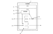
- FIG. 4 is a block diagram illustrating the configuration of the opposite terminal 4 according to the first embodiment.
- the hardware processing unit 42 includes a response circuit 43 , a buffer 44 and a bifurcation circuit 45 .
- the response circuit 43 is a circuit configured exclusively for delay measurement.
- a circuit implemented in the hardware processing unit 42 is executed without the intervention of the CPU 41 .
- the buffer 44 includes a downstream buffer and an upstream buffer.
- Buffer 44 has at least one queue.
- the bifurcation circuit 45 is provided upstream of the downstream buffer, and transmits the received delay measurement packet to the response circuit 43 and the buffer 44, respectively.
- the response circuit 43 receives the delay measurement packet from the bifurcation circuit 45 without going through the buffer 44 and immediately transmits the response packet. That is, the delay measurement packet is input to the response circuit 43 before the downstream buffer. A response packet is input to the upstream buffer. According to this configuration, it is possible to measure the delay time that does not include the downlink queuing delay of the correspondent terminal 4 .
- the system of the present embodiment generates a delay measurement packet and a response packet by the pre-installed delay measurement dedicated circuit and response dedicated circuit, and does not require software processing. Therefore, high-speed and highly accurate delay measurement can be realized without being affected by interrupt processing.
- the delay time is calculated at high speed by incorporating the delay time calculation unit 26 into the hardware processing unit 22 in advance.
- the hardware processing unit 22 since the hardware processing unit 22 has already grasped the transmission time and the reception time, it is possible to realize highly accurate delay measurement even if the processing of the delay time calculation unit 26 is implemented by software and executed by the CPU 21. can be done.
- the transmission time and the reception time may be stored in a database or the like.
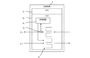
- FIG. 5 is a block diagram illustrating another configuration of the opposed terminal 4.
- the bifurcation circuit 45 is provided downstream of the downstream buffer and sequentially transmits the delay measurement packets queued in the buffer 44 to the response circuit 43 .
- the delay time including the downlink queuing delay of the correspondent terminal 4 can be measured.
- the opposite terminal 4 can be configured without the buffer 44 .
- the transmission method of the delay measurement packet and the response packet may be in-band (a method of inserting and transmitting between the main data signal) or out-of-band (a band different from the main data signal is used for transmission). method). That is, it is not limited to a technique (in-band) such as ping.
- Embodiment 2 of the present invention will be described with reference to FIG.
- this technology is applied to a time-division multiple access optical communication system, there are the following problems.
- (A) It is necessary to perform measurement for each opposed terminal 4, and the number of packets required for measurement increases in proportion to the number of opposed terminals 4, which puts pressure on the bandwidth.
- FIG. 6 is a conceptual diagram for explaining an outline of a network delay measurement system according to the second embodiment.
- a network delay measurement system 1 according to Embodiment 2 includes a plurality of correspondent terminals 4 .
- one delay measuring device 2 is connected to N opposing terminals 4 (N is an integer equal to or greater than 2).
- the delay measuring device 2 and the opposite terminal 4 communicate by time division multiplexing.
- a communication system using time division multiplexing for example, there is a PON (Passive Optical Network).
- PON Passive Optical Network
- the network configuration to which the present technology is applied is not limited to the double star type in PON.
- the processing of the measurement packet generating section 24 is partially changed in the configuration of the first embodiment described above, and the uplink is newly added.
- a transmission control unit 27 is provided. Note that the uplink transmission control unit 27 may be implemented in another device connected between the delay measuring device 2 and the correspondent terminal 4 .
- the measurement packet generator 24 broadcasts the delay measurement packet. Note that the measurement packet generation unit 24 may group a plurality of opposed terminals 4 and transmit the delay measurement packet by multicast with the group as the destination, or may transmit the delay measurement packet by unicast for each opposed terminal. Also good.
- the uplink transmission control unit 27 determines each uplink transmission timing so that the uplink transmissions to the delay measuring device 2 of the first to n-th opposing terminals 4a to 4n do not collide. Each of the determined uplink transmission timings is notified to the first to n-th opposing terminals 4a to 4n.
- each opposed terminal 4 further includes a transmission timing control section 46 and a standby time measurement section 47 in addition to the configuration of the first embodiment described above.
- the transmission timing control unit 46 performs uplink transmission based on the notified uplink transmission timing.
- the waiting time measurement unit 47 measures the waiting time from when a response packet is generated until an opportunity for uplink transmission arrives, and adds the waiting time to the response packet.
- the response packet is sent to delay measurement circuit 23 .
- the delay time calculation unit 26 subtracts the transmission time when the measurement packet was transmitted and the waiting time from the reception time when the response packet was received, and calculates the time required for the round trip as the round trip delay time.
Landscapes
- Engineering & Computer Science (AREA)
- Environmental & Geological Engineering (AREA)
- Computer Networks & Wireless Communication (AREA)
- Signal Processing (AREA)
- Data Exchanges In Wide-Area Networks (AREA)
Abstract
本発明はソフトウェアを用いず専用回路により遅延測定を実施できる。遅延測定器は、汎用プロセッサと、プログラムを用いず、予め組み込まれた回路に従って動作する遅延測定専用回路とを備える。対向端末は遅延測定器と通信する。遅延測定専用回路は、予め組み込まれた、測定パケット生成部と応答パケット受信部と遅延時間算出部とを備える。測定パケット生成部は、測定パケットを生成して対向端末へ送信し、測定パケットの送信時刻を記憶する。応答パケット受信部は、対向端末から応答パケットを受信し、応答パケットの受信時刻を記憶する。遅延時間算出部は、受信時刻から送信時刻を減算して往復遅延時間を算出する。対向端末は、予め組み込まれた、測定パケットを受信した場合に応答パケットを送信する応答専用回路を備える。
Description
本発明は、ネットワーク遅延測定システム、ネットワーク遅延測定方法及びネットワーク遅延測定装置に関する。
非特許文献1に開示されるように、ICMP(Internet Control Message Protocol)が知られている。ICMPプロトコルは、TCP/IPが実装されたコンピュータ間で、通信状態を確認するために使用される。
ICMPプロトコルを使用したネットワーク診断プログラムとしてpingが知られている。pingは、”echo request”のICMPパケットを送信してから”echo reply”のICMPパケットを受信するまでの時間を往復遅延時間として計測する。pingは、ネットワーク上における二つのノード間(遅延測定器と対向端末が1:1の構成)における往復遅延時間を計測するものである。
"Internet Control Message Protocol," RFC 792, Sept. 1981.
図7を参照して、ソフトウェアにより実装された遅延測定処理の課題について説明する。図7において、遅延測定器70はコンピュータネットワーク71を介して対向端末72に接続している。pingはソフトウェアにより実装され、CPU73、74上で遅延測定処理が演算される。CPU73、74は汎用プロセッサであり、遅延測定処理を演算中に、ソフトウェアにより実装された他機能の演算が要求されることがある。その場合、演算の優先度によっては遅延測定処理が一時停止される。これを割り込み処理という。
他機能の割り込み処理によって、遅延測定処理は演算を一時停止することから、正確な遅延時間を測定できないという課題がある。また、汎用プロセッサであるCPU73、74による演算では、必ずしも演算速度および情報伝達速度が十分ではなく、遅延時間の算出に要する時間が十分に短いとは言えない。高速大容量通信のニーズが高まる中、情報処理基盤として高速かつ高精度な遅延測定技術が求められている。高速かつ高精度な遅延測定により、ネットワーク内で発生する遅延の変動を把握し、ネットワーク制御(経路変更など)に活用することが期待されている。
本発明は、上述のような課題を解決するためになされたもので、高速かつ高精度な遅延測定が可能なネットワーク遅延測定システム、ネットワーク遅延測定方法及びネットワーク遅延測定装置を提供することを目的とする。
第1の観点は、ネットワーク遅延測定システムに関連する。
ネットワーク遅延測定システムは、遅延測定器と対向端末とを備える。
前記遅延測定器は、ロードしたプログラムに従って動作する汎用プロセッサと、前記汎用プロセッサよりもレイテンシが小さく、前記プログラムを用いず、予め組み込まれた回路に従って動作する遅延測定専用回路と、を備える。
前記対向端末は、コンピュータネットワークを介して前記遅延測定器と通信する。
前記遅延測定専用回路は、予め組み込まれた、測定パケット生成部と応答パケット受信部と遅延時間算出部とを備える。
前記測定パケット生成部は、測定パケットを生成し、該測定パケットを前記対向端末へ送信し、該測定パケットの送信時刻を記憶する。
前記応答パケット受信部は、前記対向端末から応答パケットを受信し、該応答パケットの受信時刻を記憶する。
前記遅延時間算出部は、前記受信時刻から前記送信時刻を減算して往復遅延時間を算出する。
前記対向端末は、予め組み込まれた、応答専用回路を備える。
前記応答専用回路は、前記測定パケットを受信した場合に前記応答パケットを送信する。
ネットワーク遅延測定システムは、遅延測定器と対向端末とを備える。
前記遅延測定器は、ロードしたプログラムに従って動作する汎用プロセッサと、前記汎用プロセッサよりもレイテンシが小さく、前記プログラムを用いず、予め組み込まれた回路に従って動作する遅延測定専用回路と、を備える。
前記対向端末は、コンピュータネットワークを介して前記遅延測定器と通信する。
前記遅延測定専用回路は、予め組み込まれた、測定パケット生成部と応答パケット受信部と遅延時間算出部とを備える。
前記測定パケット生成部は、測定パケットを生成し、該測定パケットを前記対向端末へ送信し、該測定パケットの送信時刻を記憶する。
前記応答パケット受信部は、前記対向端末から応答パケットを受信し、該応答パケットの受信時刻を記憶する。
前記遅延時間算出部は、前記受信時刻から前記送信時刻を減算して往復遅延時間を算出する。
前記対向端末は、予め組み込まれた、応答専用回路を備える。
前記応答専用回路は、前記測定パケットを受信した場合に前記応答パケットを送信する。
第2の観点は、遅延測定器と対向端末とを用いたネットワーク遅延測定方法に関連する。
前記遅延測定器は、ロードしたプログラムに従って動作する汎用プロセッサと、前記汎用プロセッサよりもレイテンシが小さく、前記プログラムを用いず、予め組み込まれた回路に従って動作する遅延測定専用回路と、を備える。
前記対向端末は、コンピュータネットワークを介して前記遅延測定器と通信し、予め組み込まれた回路に従って動作する応答専用回路を備える。
前記ネットワーク遅延測定方法は、測定パケット生成ステップと、応答パケット送信ステップと、応答パケット受信ステップと、遅延時間算出ステップとを備える。
前記測定パケット生成ステップは、前記遅延測定専用回路を用いて、測定パケットを生成し、該測定パケットを前記対向端末へ送信し、該測定パケットの送信時刻を記憶する。
前記応答パケット送信ステップは、前記対向端末が前記測定パケットを受信した場合に、前記応答専用回路を用いて応答パケットを送信する。
前記応答パケット受信ステップは、前記遅延測定専用回路を用いて、前記対向端末から前記応答パケットを受信し、該応答パケットの受信時刻を記憶する。
前記遅延時間算出ステップは、前記汎用プロセッサまたは前記遅延測定専用回路を用いて、前記受信時刻から前記送信時刻を減算して往復遅延時間を算出する。
前記遅延測定器は、ロードしたプログラムに従って動作する汎用プロセッサと、前記汎用プロセッサよりもレイテンシが小さく、前記プログラムを用いず、予め組み込まれた回路に従って動作する遅延測定専用回路と、を備える。
前記対向端末は、コンピュータネットワークを介して前記遅延測定器と通信し、予め組み込まれた回路に従って動作する応答専用回路を備える。
前記ネットワーク遅延測定方法は、測定パケット生成ステップと、応答パケット送信ステップと、応答パケット受信ステップと、遅延時間算出ステップとを備える。
前記測定パケット生成ステップは、前記遅延測定専用回路を用いて、測定パケットを生成し、該測定パケットを前記対向端末へ送信し、該測定パケットの送信時刻を記憶する。
前記応答パケット送信ステップは、前記対向端末が前記測定パケットを受信した場合に、前記応答専用回路を用いて応答パケットを送信する。
前記応答パケット受信ステップは、前記遅延測定専用回路を用いて、前記対向端末から前記応答パケットを受信し、該応答パケットの受信時刻を記憶する。
前記遅延時間算出ステップは、前記汎用プロセッサまたは前記遅延測定専用回路を用いて、前記受信時刻から前記送信時刻を減算して往復遅延時間を算出する。
第3の観点は、ネットワーク遅延測定装置に関連する。
ネットワーク遅延測定装置は、コンピュータネットワークを介して対向端末と通信する遅延測定器である。
前記ネットワーク遅延測定装置は、ロードしたプログラムに従って動作する汎用プロセッサと、前記汎用プロセッサよりもレイテンシが小さく、前記プログラムを用いずに予め組み込まれた回路に従って動作する遅延測定専用回路と、を備える。
前記遅延測定専用回路は、予め組み込まれた、測定パケット生成部と応答パケット受信部と遅延時間算出部とを備える。
前記測定パケット生成部は、測定パケットを生成し、該測定パケットを前記対向端末へ送信し、該測定パケットの送信時刻を記憶する。
前記応答パケット受信部は、前記対向端末から応答パケットを受信し、該応答パケットの受信時刻を記憶する。
前記遅延時間算出部は、前記受信時刻から前記送信時刻を減算して往復遅延時間を算出する。
ネットワーク遅延測定装置は、コンピュータネットワークを介して対向端末と通信する遅延測定器である。
前記ネットワーク遅延測定装置は、ロードしたプログラムに従って動作する汎用プロセッサと、前記汎用プロセッサよりもレイテンシが小さく、前記プログラムを用いずに予め組み込まれた回路に従って動作する遅延測定専用回路と、を備える。
前記遅延測定専用回路は、予め組み込まれた、測定パケット生成部と応答パケット受信部と遅延時間算出部とを備える。
前記測定パケット生成部は、測定パケットを生成し、該測定パケットを前記対向端末へ送信し、該測定パケットの送信時刻を記憶する。
前記応答パケット受信部は、前記対向端末から応答パケットを受信し、該応答パケットの受信時刻を記憶する。
前記遅延時間算出部は、前記受信時刻から前記送信時刻を減算して往復遅延時間を算出する。
第4の観点は、ネットワーク遅延測定装置に関連する。
ネットワーク遅延測定装置は、コンピュータネットワークを介して遅延測定器と通信する対向端末である。
前記ネットワーク遅延測定装置は、予め組み込まれた回路に従って動作する応答専用回路と、バッファと、受信した測定パケットを前記応答専用回路と前記バッファとにそれぞれ送信する二分岐回路と、を備える。
前記応答専用回路は、前記バッファを介さずに前記二分岐回路から前記測定パケットを受信し、前記応答パケットを送信する。
ネットワーク遅延測定装置は、コンピュータネットワークを介して遅延測定器と通信する対向端末である。
前記ネットワーク遅延測定装置は、予め組み込まれた回路に従って動作する応答専用回路と、バッファと、受信した測定パケットを前記応答専用回路と前記バッファとにそれぞれ送信する二分岐回路と、を備える。
前記応答専用回路は、前記バッファを介さずに前記二分岐回路から前記測定パケットを受信し、前記応答パケットを送信する。
本発明によれば、予め組み込まれた遅延測定専用回路および応答専用回路により、遅延測定パケットおよび応答パケットが生成され、ソフトウェア処理は必要としない。そのため、本発明によれば、割り込み処理の影響を受けることなく、高速かつ高精度な遅延測定が可能である。このような技術によれば、ネットワーク内で発生する遅延の変動を把握し、ネットワーク制御(経路変更など)に活用することができる。
以下、図面を参照して本発明の実施の形態について詳細に説明する。尚、各図において共通する要素には、同一の符号を付して重複する説明を省略する。
実施の形態1.
(1)ネットワーク遅延測定システム
図1は、実施の形態1に係るネットワーク遅延測定システムの概要を説明するための概念図である。図1に示すネットワーク遅延測定システム1は、遅延測定器2、コンピュータネットワーク3、少なくとも1つの対向端末4、複数の分岐器5を備える。図1には対向端末4として、第1対向端末4a、第2対向端末4b、第3対向端末4cが例示されている。遅延測定器2および対向端末4は、ネットワーク遅延測定装置として機能する。
(1)ネットワーク遅延測定システム
図1は、実施の形態1に係るネットワーク遅延測定システムの概要を説明するための概念図である。図1に示すネットワーク遅延測定システム1は、遅延測定器2、コンピュータネットワーク3、少なくとも1つの対向端末4、複数の分岐器5を備える。図1には対向端末4として、第1対向端末4a、第2対向端末4b、第3対向端末4cが例示されている。遅延測定器2および対向端末4は、ネットワーク遅延測定装置として機能する。
遅延測定器2は、分岐器5およびコンピュータネットワーク3を介して、各対向端末4へ接続している。遅延測定器2は、対向端末4との間の遅延時間を測定する機能を備える装置である。
対向端末4は、遅延時間を測定する対象の装置である。対向端末4は、遅延測定器2からの要求信号(遅延測定パケット)に応じて応答信号(応答パケット)を送信する機能を備える装置である。対向端末4は、パーソナルコンピュータのようなユーザエンド端末でもよいし、ONU(Optical Network Unit)のようなネットワーク上の端末であってもよい。また、対向端末4は1台でもよいし、複数台でもよい。
コンピュータネットワーク3は、有線または無線のネットワークであり、ネットワークの種類および規模は問わない。一例として、コンピュータネットワーク3は、光ネットワークである。
分岐器5は、遅延測定器2と対向端末4をネットワーク化するための装置である。分岐器5は、例えば光ネットワークにおいては光スイッチや光カプラなどである。
図2は、実施の形態1に係るネットワーク遅延測定装置の概要について説明するための図である。図2において、遅延測定器2と対向端末4は1:1の構成であるが、1:nの構成であってもよい。
遅延測定器2は、メモリ(図示省略)、CPU21およびハードウェア処理部22を有する。対向端末4は、メモリ(図示省略)、CPU41およびハードウェア処理部42を有する。CPU21、41は、メモリからロードしたプログラムに従って動作する汎用プロセッサである。プログラムの処理内容は限定されない。ハードウェア処理部22、42は、プログラムを用いず、予め組み込まれた回路に従って動作する遅延測定のための専用回路である。ハードウェア処理部22、42は、内部メモリを備える。ハードウェア処理部22、42は、例えば、FPGA、GPUを含む。CPU21、41は汎用のOSや汎用バスを経由して通信するため、割り込み処理が発生すると遅延が発生するが、ハードウェア処理部22、42はデータソースにダイレクトにアクセスできることに加え、ロジックが予め組み込まれているので、高速かつ一定の速度で応答が返ってくる。
遅延測定器2および対向端末4の間の遅延時間の測定は、専用回路である遅延測定回路23および応答回路43により実行される。
(2)遅延測定器
次に、図3を参照して遅延測定器2について説明する。図3は、実施の形態1に係る遅延測定器2が有する構成を例示するブロック図である。ハードウェア処理部22は、遅延測定専用の回路として構成された遅延測定回路23を備える。ハードウェア処理部22に実装された遅延測定回路23は、CPU21を介さずに実行される。
次に、図3を参照して遅延測定器2について説明する。図3は、実施の形態1に係る遅延測定器2が有する構成を例示するブロック図である。ハードウェア処理部22は、遅延測定専用の回路として構成された遅延測定回路23を備える。ハードウェア処理部22に実装された遅延測定回路23は、CPU21を介さずに実行される。
遅延測定回路23は、予め組み込まれた測定パケット生成部24、応答パケット受信部25、遅延時間算出部26を備える。
測定パケット生成部24は、遅延測定パケットを生成し、遅延測定パケットを対向端末4へ送信する。また、測定パケット生成部24は、遅延測定パケットを送信した送信時刻を記憶する。
応答パケット受信部25は、対向端末4から応答パケットを受信し、該応答パケットの受信時刻を記憶する。送信時刻および受信時刻は、例えば遅延測定回路23の内部メモリに記憶される。
遅延時間算出部26は、応答パケットを受信した受信時刻から遅延測定パケットを送信した送信時刻を減算して、往復に要した時間を往復遅延時間として算出する。
(3)対向端末
次に、図4を参照して対向端末4について説明する。図4は、実施の形態1に係る対向端末4が有する構成を例示するブロック図である。ハードウェア処理部42は、応答回路43、バッファ44、二分岐回路45を備える。応答回路43は、遅延測定専用に構成された回路である。ハードウェア処理部42に実装された回路は、CPU41を介さずに実行される。
次に、図4を参照して対向端末4について説明する。図4は、実施の形態1に係る対向端末4が有する構成を例示するブロック図である。ハードウェア処理部42は、応答回路43、バッファ44、二分岐回路45を備える。応答回路43は、遅延測定専用に構成された回路である。ハードウェア処理部42に実装された回路は、CPU41を介さずに実行される。
バッファ44は、下りバッファと上りバッファを含む。バッファ44は少なくとも1つのキューを有する。
二分岐回路45は、下りバッファの上流に設けられ、受信した遅延測定パケットを応答回路43とバッファ44とにそれぞれ送信する。
応答回路43は、バッファ44を介さずに二分岐回路45から遅延測定パケットを受信し、すぐに応答パケットを送信する。すなわち、遅延測定パケットは下りバッファより前に応答回路43に入力される。応答パケットは上りバッファに入力される。この構成によれば、対向端末4の下りキューイング遅延を含めない遅延時間を測定することができる。
(4)効果
以上説明したように、本実施形態のシステムは、予め組み込まれた遅延測定専用回路および応答専用回路により、遅延測定パケットおよび応答パケットが生成され、ソフトウェア処理を必要としない。そのため、割り込み処理の影響を受けることなく、高速かつ高精度な遅延測定を実現できる。
以上説明したように、本実施形態のシステムは、予め組み込まれた遅延測定専用回路および応答専用回路により、遅延測定パケットおよび応答パケットが生成され、ソフトウェア処理を必要としない。そのため、割り込み処理の影響を受けることなく、高速かつ高精度な遅延測定を実現できる。
(5)変形例
変形例について説明する。上述した実施の形態1のシステムにおいては、遅延時間算出部26をハードウェア処理部22に予め組み入れることで遅延時間を高速に算出している。ところで、送信時刻および受信時刻をハードウェア処理部22にて把握済みであることから、遅延時間算出部26の処理をソフトウェアにより実装しCPU21で実行することとしても高精度な遅延測定を実現することができる。また、この場合、送信時刻および受信時刻はデータベース等に保存されてもよい。
変形例について説明する。上述した実施の形態1のシステムにおいては、遅延時間算出部26をハードウェア処理部22に予め組み入れることで遅延時間を高速に算出している。ところで、送信時刻および受信時刻をハードウェア処理部22にて把握済みであることから、遅延時間算出部26の処理をソフトウェアにより実装しCPU21で実行することとしても高精度な遅延測定を実現することができる。また、この場合、送信時刻および受信時刻はデータベース等に保存されてもよい。
図5は、対向端末4の別の構成を例示するブロック図である。この構成例では、二分岐回路45は、下りバッファの下流に設けられ、バッファ44にキューイングされた遅延測定パケットを順に応答回路43へ送信する。この構成例によれば、対向端末4の下りキューイング遅延を含めた遅延時間を測定することができる。
また、対向端末4は、バッファ44を有さない構成とすることも可能である。
また、遅延測定パケット及び応答パケットの送信方法は、インバンド(データ主信号の間に挿入して送信する方式)であっても、アウトオブバンド(データ主信号とは異なる帯域を用いて送信する方式)であってもよい。すなわち、pingのような手法(インバンド)に限定されるものではない。
実施の形態2.
次に、図6を参照して本発明の実施の形態2について説明する。本技術を時分割多重アクセスの光通信システムに適用する場合、以下の課題がある。
(A)対向端末4毎に計測を実施する必要があり、対向端末4の数に比例して計測に必要なパケット数が増加し、帯域を圧迫する。
(B)マルチアクセスによる送信待機遅延が、計測される遅延時間に含まれ、正確な経路遅延を計測できない。
そこで、本実施形態では、時分割多重化方式で通信するシステムにおいて、高速かつ高精度な遅延測定を実現することとした。
次に、図6を参照して本発明の実施の形態2について説明する。本技術を時分割多重アクセスの光通信システムに適用する場合、以下の課題がある。
(A)対向端末4毎に計測を実施する必要があり、対向端末4の数に比例して計測に必要なパケット数が増加し、帯域を圧迫する。
(B)マルチアクセスによる送信待機遅延が、計測される遅延時間に含まれ、正確な経路遅延を計測できない。
そこで、本実施形態では、時分割多重化方式で通信するシステムにおいて、高速かつ高精度な遅延測定を実現することとした。
(1)ネットワーク遅延測定システム
図6は、実施の形態2に係るネットワーク遅延測定システムの概要を説明するための概念図である。実施の形態2に係るネットワーク遅延測定システム1は、複数の対向端末4を備える。図6に示す例では、1つの遅延測定器2はN台の対向端末4に接続している(Nは2以上の整数)。
図6は、実施の形態2に係るネットワーク遅延測定システムの概要を説明するための概念図である。実施の形態2に係るネットワーク遅延測定システム1は、複数の対向端末4を備える。図6に示す例では、1つの遅延測定器2はN台の対向端末4に接続している(Nは2以上の整数)。
遅延測定器2および対向端末4は、時分割多重化方式で通信する。時分割多重による通信システムとしては、例えばPON(Passive Optical Network)がある。ただし、本技術が適用されるネットワーク構成はPONにおけるダブルスター型に限定されない。
(2)遅延測定器
実施の形態2に係る遅延測定器2の遅延測定回路23は、上述した実施の形態1の構成において測定パケット生成部24の処理が一部変更され、かつ、新たに上り送信制御部27を備える。なお、上り送信制御部27は、遅延測定器2と対向端末4との間に接続される別の装置に実装されていても良い。
実施の形態2に係る遅延測定器2の遅延測定回路23は、上述した実施の形態1の構成において測定パケット生成部24の処理が一部変更され、かつ、新たに上り送信制御部27を備える。なお、上り送信制御部27は、遅延測定器2と対向端末4との間に接続される別の装置に実装されていても良い。
測定パケット生成部24は、ブロードキャストで遅延測定パケットを送信する。なお、測定パケット生成部24は、複数の対向端末4をグループ化して当該グループを宛先としてマルチキャストで遅延測定パケットを送信しても良いし、対向端末毎のユニキャストで遅延測定パケットを送信しても良い。
上り送信制御部27は、第1対向端末4a~第n対向端末4nの遅延測定器2への上り送信が衝突しないように各上り送信タイミングを決定する。決定された各上り送信タイミングは、第1対向端末4a~第n対向端末4nへ通知される。
(3)対向端末
実施の形態2に係る各対向端末4の応答回路43は、上述した実施の形態1の構成に加えて送信タイミング制御部46と待機時間測定部47とを更に備える。
実施の形態2に係る各対向端末4の応答回路43は、上述した実施の形態1の構成に加えて送信タイミング制御部46と待機時間測定部47とを更に備える。
送信タイミング制御部46は、通知された上り送信タイミングに基づいて上り送信を実行する。
待機時間測定部47は、応答パケットが生成されてから上り送信の機会が訪れるまでの待機時間を計測し、該待機時間を応答パケットに付与する。応答パケットは遅延測定回路23へ送信される。
遅延時間算出部26は、応答パケットを受信した受信時刻から、測定パケットを送信した送信時刻および待機時間を減算して、往復に要した時間を、往復遅延時間として算出する。
(4)効果
以上説明したように、本実施形態のシステムによれば、実施の形態1と同様の効果を奏する。すなわち、本実施形態によれば、割り込み処理の影響を受けずに、高速かつ高精度な遅延測定を実現できる。また、応答パケットが生成されてから送信されるまでの待機時間を測定することにより、マルチアクセスにおける送信待機遅延の影響を除外でき、正確な経路遅延の測定が可能である。さらに、ブロードキャストまたはマルチキャストにて遅延測定パケットが送信されるため、遅延計測に必要なパケット数・オーバヘッドを削減でき、ネットワークの帯域圧迫を抑制できる。
以上説明したように、本実施形態のシステムによれば、実施の形態1と同様の効果を奏する。すなわち、本実施形態によれば、割り込み処理の影響を受けずに、高速かつ高精度な遅延測定を実現できる。また、応答パケットが生成されてから送信されるまでの待機時間を測定することにより、マルチアクセスにおける送信待機遅延の影響を除外でき、正確な経路遅延の測定が可能である。さらに、ブロードキャストまたはマルチキャストにて遅延測定パケットが送信されるため、遅延計測に必要なパケット数・オーバヘッドを削減でき、ネットワークの帯域圧迫を抑制できる。
以上、本発明の実施の形態について説明したが、本発明は、上記の実施の形態に限定されるものではなく、本発明の趣旨を逸脱しない範囲で種々変形して実施することができる。上述した実施の形態において各要素の個数、数量、量、範囲等の数に言及した場合、特に明示した場合や原理的に明らかにその数に特定される場合を除いて、その言及した数にこの発明が限定されるものではない。また、上述した実施の形態において説明する構造等は、特に明示した場合や明らかに原理的にそれに特定される場合を除いて、この発明に必ずしも必須のものではない。
1 ネットワーク遅延測定システム
2 遅延測定器
3 コンピュータネットワーク
4 対向端末
5 分岐器
21,41 CPU
22,42 ハードウェア処理部
23 遅延測定回路
24 測定パケット生成部
25 応答パケット受信部
26 遅延時間算出部
27 送信制御部
43 応答回路
44 バッファ
45 二分岐回路
46 送信タイミング制御部
47 待機時間測定部
70 遅延測定器
71 コンピュータネットワーク
72 対向端末
2 遅延測定器
3 コンピュータネットワーク
4 対向端末
5 分岐器
21,41 CPU
22,42 ハードウェア処理部
23 遅延測定回路
24 測定パケット生成部
25 応答パケット受信部
26 遅延時間算出部
27 送信制御部
43 応答回路
44 バッファ
45 二分岐回路
46 送信タイミング制御部
47 待機時間測定部
70 遅延測定器
71 コンピュータネットワーク
72 対向端末
Claims (8)
- ロードしたプログラムに従って動作する汎用プロセッサと、前記汎用プロセッサよりもレイテンシが小さく、前記プログラムを用いず、予め組み込まれた回路に従って動作する遅延測定専用回路と、を備える遅延測定器と、
コンピュータネットワークを介して前記遅延測定器と通信する対向端末と、を備え、
前記遅延測定専用回路は、予め組み込まれた、
測定パケットを生成し、該測定パケットを前記対向端末へ送信し、該測定パケットの送信時刻を記憶する測定パケット生成部と、
前記対向端末から応答パケットを受信し、該応答パケットの受信時刻を記憶する応答パケット受信部と、を備え、
前記汎用プロセッサまたは前記遅延測定専用回路は、
前記受信時刻から前記送信時刻を減算して往復遅延時間を算出する遅延時間算出部を備え、
前記対向端末は、予め組み込まれた、
前記測定パケットを受信した場合に前記応答パケットを送信する応答専用回路を備えること、
を特徴とするネットワーク遅延測定システム。 - 前記対向端末は、
バッファと、
受信した前記測定パケットを前記応答専用回路と前記バッファとにそれぞれ送信する二分岐回路と、を備え、
前記応答専用回路は、前記バッファを介さずに前記二分岐回路から前記測定パケットを受信し、前記応答パケットを送信すること、
を特徴とする請求項1に記載のネットワーク遅延測定システム。 - 前記測定パケット生成部は、ブロードキャストまたはマルチキャストで前記測定パケットを送信すること、
を特徴とする請求項1又は2に記載のネットワーク遅延測定システム。 - 前記遅延測定器および前記対向端末は、時分割多重化方式で通信し、
前記対向端末は、少なくとも第1対向端末および第2対向端末を含み、
前記ネットワーク遅延測定システムは、前記第1対向端末および前記第2対向端末の前記遅延測定器への上り送信が衝突しないように上り送信タイミングを決定する上り送信制御部を備え、
前記応答専用回路は、
前記決定された上り送信タイミングに基づいて前記上り送信を実行する送信タイミング制御部と、
前記応答パケットが生成されてから前記上り送信の機会が訪れるまでの待機時間を計測し、該待機時間を前記応答パケットに付与する待機時間測定部と、を備え、
前記遅延時間算出部は、前記応答パケットを受信した前記受信時刻から、前記測定パケットを送信した前記送信時刻および前記待機時間を減算して、前記往復遅延時間を算出すること、
を特徴とする請求項3に記載のネットワーク遅延測定システム。 - ロードしたプログラムに従って動作する汎用プロセッサと、前記汎用プロセッサよりもレイテンシが小さく、前記プログラムを用いず、予め組み込まれた回路に従って動作する遅延測定専用回路と、を備える遅延測定器と、
コンピュータネットワークを介して前記遅延測定器と通信し、予め組み込まれた回路に従って動作する応答専用回路を備える対向端末と、を用いたネットワーク遅延測定方法であって、
前記遅延測定専用回路を用いて、測定パケットを生成し、該測定パケットを前記対向端末へ送信し、該測定パケットの送信時刻を記憶する測定パケット生成ステップと、
前記対向端末が前記測定パケットを受信した場合に、前記応答専用回路を用いて応答パケットを送信する応答パケット送信ステップと、
前記遅延測定専用回路を用いて、前記対向端末から前記応答パケットを受信し、該応答パケットの受信時刻を記憶する応答パケット受信ステップと、
前記汎用プロセッサまたは前記遅延測定専用回路を用いて、前記受信時刻から前記送信時刻を減算して往復遅延時間を算出する遅延時間算出ステップと、
を備えることを特徴とするネットワーク遅延測定方法。 - 前記対向端末は、
バッファと、
受信した前記測定パケットを前記応答専用回路と前記バッファとにそれぞれ送信する二分岐回路と、を備え、
前記応答パケット送信ステップは、前記バッファを介さずに前記二分岐回路から前記測定パケットを受信し、前記応答パケットを送信すること、
を特徴とする請求項5に記載のネットワーク遅延測定方法。 - コンピュータネットワークを介して対向端末と通信するネットワーク遅延測定装置であって、
ロードしたプログラムに従って動作する汎用プロセッサと、
前記汎用プロセッサよりもレイテンシが小さく、前記プログラムを用いずに予め組み込まれた回路に従って動作する遅延測定専用回路と、を備え、
前記遅延測定専用回路は、予め組み込まれた、
測定パケットを生成し、該測定パケットを前記対向端末へ送信し、該測定パケットの送信時刻を記憶する測定パケット生成部と、
前記対向端末から応答パケットを受信し、該応答パケットの受信時刻を記憶する応答パケット受信部と、を備え、
前記汎用プロセッサまたは前記遅延測定専用回路は、
前記受信時刻から前記送信時刻を減算して往復遅延時間を算出する遅延時間算出部を備えること、
を特徴とするネットワーク遅延測定装置。 - コンピュータネットワークを介して遅延測定器と通信するネットワーク遅延測定装置であって、
予め組み込まれた回路に従って動作する応答専用回路と、
バッファと、
受信した測定パケットを前記応答専用回路と前記バッファとにそれぞれ送信する二分岐回路と、を備え、
前記応答専用回路は、前記バッファを介さずに前記二分岐回路から前記測定パケットを受信し、応答パケットを送信すること、
を特徴とするネットワーク遅延測定装置。
Priority Applications (3)
| Application Number | Priority Date | Filing Date | Title |
|---|---|---|---|
| US18/560,933 US20240259285A1 (en) | 2021-05-21 | 2021-05-21 | Network delay measuring system, network delay measuring method and network delay measuring device |
| PCT/JP2021/019438 WO2022244262A1 (ja) | 2021-05-21 | 2021-05-21 | ネットワーク遅延測定システム、ネットワーク遅延測定方法及びネットワーク遅延測定装置 |
| JP2023522182A JP7687390B2 (ja) | 2021-05-21 | 2021-05-21 | ネットワーク遅延測定システム、ネットワーク遅延測定方法及びネットワーク遅延測定装置 |
Applications Claiming Priority (1)
| Application Number | Priority Date | Filing Date | Title |
|---|---|---|---|
| PCT/JP2021/019438 WO2022244262A1 (ja) | 2021-05-21 | 2021-05-21 | ネットワーク遅延測定システム、ネットワーク遅延測定方法及びネットワーク遅延測定装置 |
Publications (1)
| Publication Number | Publication Date |
|---|---|
| WO2022244262A1 true WO2022244262A1 (ja) | 2022-11-24 |
Family
ID=84140229
Family Applications (1)
| Application Number | Title | Priority Date | Filing Date |
|---|---|---|---|
| PCT/JP2021/019438 Ceased WO2022244262A1 (ja) | 2021-05-21 | 2021-05-21 | ネットワーク遅延測定システム、ネットワーク遅延測定方法及びネットワーク遅延測定装置 |
Country Status (3)
| Country | Link |
|---|---|
| US (1) | US20240259285A1 (ja) |
| JP (1) | JP7687390B2 (ja) |
| WO (1) | WO2022244262A1 (ja) |
Citations (4)
| Publication number | Priority date | Publication date | Assignee | Title |
|---|---|---|---|---|
| JP2000209205A (ja) * | 1999-01-20 | 2000-07-28 | Fujitsu I-Network Systems Ltd | ネットワ―ク内遅延時間測定装置 |
| JP2002368770A (ja) * | 2001-06-08 | 2002-12-20 | Hitachi Cable Ltd | 遅延時間測定機能付きスイッチングハブ |
| JP2010088040A (ja) * | 2008-10-02 | 2010-04-15 | Hitachi Cable Ltd | 中継機器間の中継遅延時間の測定方法および測定システム、並びに中継機器 |
| JP2013153367A (ja) * | 2012-01-26 | 2013-08-08 | Fujitsu Ltd | 伝送装置および遅延測定方法 |
Family Cites Families (2)
| Publication number | Priority date | Publication date | Assignee | Title |
|---|---|---|---|---|
| US7969900B2 (en) * | 2002-06-24 | 2011-06-28 | Paradyne Corporation | Determination of network performance characteristics |
| JP4930451B2 (ja) * | 2008-05-07 | 2012-05-16 | 富士通株式会社 | 基地局装置、基地局管理装置、及び、基地局管理システム |
-
2021
- 2021-05-21 US US18/560,933 patent/US20240259285A1/en not_active Abandoned
- 2021-05-21 JP JP2023522182A patent/JP7687390B2/ja active Active
- 2021-05-21 WO PCT/JP2021/019438 patent/WO2022244262A1/ja not_active Ceased
Patent Citations (4)
| Publication number | Priority date | Publication date | Assignee | Title |
|---|---|---|---|---|
| JP2000209205A (ja) * | 1999-01-20 | 2000-07-28 | Fujitsu I-Network Systems Ltd | ネットワ―ク内遅延時間測定装置 |
| JP2002368770A (ja) * | 2001-06-08 | 2002-12-20 | Hitachi Cable Ltd | 遅延時間測定機能付きスイッチングハブ |
| JP2010088040A (ja) * | 2008-10-02 | 2010-04-15 | Hitachi Cable Ltd | 中継機器間の中継遅延時間の測定方法および測定システム、並びに中継機器 |
| JP2013153367A (ja) * | 2012-01-26 | 2013-08-08 | Fujitsu Ltd | 伝送装置および遅延測定方法 |
Also Published As
| Publication number | Publication date |
|---|---|
| JP7687390B2 (ja) | 2025-06-03 |
| US20240259285A1 (en) | 2024-08-01 |
| JPWO2022244262A1 (ja) | 2022-11-24 |
Similar Documents
| Publication | Publication Date | Title |
|---|---|---|
| Kannan et al. | Precise time-synchronization in the data-plane using programmable switching asics | |
| KR101259230B1 (ko) | 링크 대역 추정 장치 및 링크 대역 추정 방법 | |
| CN107508719B (zh) | 测量网络时延的方法、装置及网络节点 | |
| US9419738B2 (en) | Communication device, method and system for queueing packets to be transmitted | |
| Lee et al. | Dx: Latency-based congestion control for datacenters | |
| CN101771585B (zh) | 一种网络延时测量设备及其方法 | |
| US20150186318A1 (en) | Dragonfly processor interconnect network | |
| US11349587B2 (en) | Generating a timestamp | |
| US10181994B2 (en) | Probing a network | |
| US20160315840A1 (en) | Method for measuring transmission delay of optical transport network device and source OTN device | |
| CN110932814A (zh) | 软件定义的网络授时安全防护方法、装置及系统 | |
| EP3474499A1 (en) | Network performance detection method and apparatus | |
| JP5675703B2 (ja) | 通信装置、制御装置及びプログラム | |
| US9331803B2 (en) | System and method of synchronization among a control apparatus and a plurality of terminals | |
| JP2010141444A (ja) | 帯域計測プログラム、方法及び装置 | |
| JP7687390B2 (ja) | ネットワーク遅延測定システム、ネットワーク遅延測定方法及びネットワーク遅延測定装置 | |
| JP4815534B2 (ja) | パケット遅延特性計測装置及び方法 | |
| JP6195017B2 (ja) | 通信装置、通信システム、通信方法および通信用プログラムが記憶された記憶媒体 | |
| Bartols et al. | Performance analysis of time-triggered ether-networks using off-the-shelf-components | |
| JP6578258B2 (ja) | 光終端装置および伝搬遅延時間測定方法 | |
| CN107171887B (zh) | 一种网络带宽测试方法、客户端及网络带宽测试系统 | |
| CN100396017C (zh) | 覆盖路由网络中的虚链路性能实时测量方法 | |
| JP2004135065A (ja) | 送信端末、受信端末及びデータ伝送システム | |
| CN115604341B (zh) | 一种信息传输方法及其相关设备 | |
| JP6348377B2 (ja) | コンテンツ配信ネットワークの通信装置及びプログラム |
Legal Events
| Date | Code | Title | Description |
|---|---|---|---|
| WWE | Wipo information: entry into national phase |
Ref document number: 2023522182 Country of ref document: JP |
|
| WWE | Wipo information: entry into national phase |
Ref document number: 18560933 Country of ref document: US |
|
| NENP | Non-entry into the national phase |
Ref country code: DE |
|
| 122 | Ep: pct application non-entry in european phase |
Ref document number: 21940873 Country of ref document: EP Kind code of ref document: A1 |