WO2022244142A1 - 機構制御系設計装置および機構制御系設計方法 - Google Patents
機構制御系設計装置および機構制御系設計方法 Download PDFInfo
- Publication number
- WO2022244142A1 WO2022244142A1 PCT/JP2021/018990 JP2021018990W WO2022244142A1 WO 2022244142 A1 WO2022244142 A1 WO 2022244142A1 JP 2021018990 W JP2021018990 W JP 2021018990W WO 2022244142 A1 WO2022244142 A1 WO 2022244142A1
- Authority
- WO
- WIPO (PCT)
- Prior art keywords
- control system
- design
- mechanism control
- system design
- dimensions
- Prior art date
- Legal status (The legal status is an assumption and is not a legal conclusion. Google has not performed a legal analysis and makes no representation as to the accuracy of the status listed.)
- Ceased
Links
Images





Classifications
-
- G—PHYSICS
- G06—COMPUTING OR CALCULATING; COUNTING
- G06F—ELECTRIC DIGITAL DATA PROCESSING
- G06F30/00—Computer-aided design [CAD]
- G06F30/20—Design optimisation, verification or simulation
- G06F30/23—Design optimisation, verification or simulation using finite element methods [FEM] or finite difference methods [FDM]
Definitions
- the present disclosure relates to a mechanism control system design device and a mechanism control system design method for designing a mechanism control system consisting of a mechanism system and a control system.
- Patent Literature 2 discloses an automatic analysis method that changes a three-dimensional model according to a change in dimensions of an analysis object and performs FEM analysis according to preset analysis conditions.
- the mechanism system design parameters of the equation of state created from the equation of motion of the mechanism system are optimized. Even if the mechanical system design parameters of the equation of state are optimized, design results that are difficult to achieve may be obtained, such as reducing the mass and increasing the rigidity. In this case, it becomes difficult to design a mechanism system that satisfies the calculated mechanism system design parameters, or it takes a long time to design the mechanism system, making it difficult to realize the optimum design of the mechanism control system. .
- the present disclosure has been made in view of the above, and an object thereof is to obtain a mechanism control system design device that can realize the optimum design of a mechanism control system.
- the mechanism control system design device is a mechanism control system design device for designing a mechanism control system consisting of a mechanism system and a control system.
- a mechanism control system design device includes a shape changing unit that changes mechanism dimensions indicated by shape data of a mechanism system, and a structure analysis unit that analyzes the structure of the mechanism system represented by the shape data, which is an analysis target.
- a mechanism system design parameter calculation unit that calculates the design parameters of the mechanism system based on the analysis result of the structure to be analyzed; By substituting the design parameters of the control system into the control model representing It comprises an objective function calculator for calculating and a simultaneous optimum design part for determining the design parameters of the mechanism dimension and the control system for optimizing the objective function at the same time.
- the mechanism control system design device has the effect that it is possible to realize the optimum design of the mechanism control system.
- FIG. 1 is a diagram showing a functional configuration of a mechanism control system design device according to a first embodiment
- FIG. FIG. 2 shows an example of a positioning device to which the mechanism control system design method of the first embodiment is applied
- FIG. 3 is a diagram for explaining the vibration mode of the positioning device shown in FIG. 2
- FIG. 5 is a diagram for explaining an example of fixation and contact conditions for FEM analysis in the mechanism control system design apparatus according to the first embodiment
- FIG. 4 is a diagram for explaining the definition of the objective function calculated by the objective function calculator of the mechanism control system design apparatus according to the first embodiment
- FIG. 11 is a diagram showing a functional configuration of a mechanism control system design device according to a second embodiment
- FIG. 9 is a diagram showing an example of a response surface set in a response surface calculator of a mechanism control system design apparatus according to a second embodiment
- FIG. 10 is a diagram showing a functional configuration of a mechanism control system design device according to a third embodiment
- FIG. 11 is a diagram for explaining an example of applying the extraction of mechanism dimensions according to the third embodiment to the design of a positioning device
- FIG. 10 is a diagram showing a functional configuration of a mechanism control system design device according to a fourth embodiment
- FIG. 15 is a diagram for explaining an example of applying the degree of freedom reduction according to the fourth embodiment to the design of a positioning device
- FIG. 4 is a diagram showing a first configuration example of hardware that realizes the mechanism control system design device according to the first to fourth embodiments
- FIG. 10 is a diagram showing a second configuration example of hardware that realizes the mechanism control system design device according to the first to fourth embodiments;
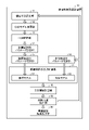
- FIG. 1 is a diagram showing the functional configuration of a mechanism control system design device 10 according to the first embodiment.
- the mechanism control system design device 10 performs calculations for designing a mechanism control system consisting of a mechanism system and a control system.
- the mechanism control system is applied to devices that require highly accurate positioning, such as positioning devices and robot manipulators.
- the mechanism control system design device 10 includes a mechanism dimension setting unit 11 that sets mechanism dimensions, a CAD model change unit 12 that changes a CAD (Computer-Aided Design) model, which is a three-dimensional model of the mechanism system, and a mechanism system design using FEM.
- a FEM analysis unit 13 that analyzes the structure of the mechanism, a mechanism system design parameter calculation unit 14 that calculates the design parameters of the mechanism system, a mechanism system design parameter setting unit 15 that sets the design parameters of the mechanism system, and a control system design parameter and a control system design parameter setting unit 16 that sets the
- the design parameters of the mechanical system are hereinafter referred to as mechanical system design parameters.
- the design parameters of the control system are called control system design parameters.
- the mechanism control system design device 10 also includes a mechanism control system behavior calculation unit 17 that calculates the behavior of the mechanism control system, an objective function calculation unit 18 that calculates the objective function of the mechanism control system, and a simultaneous optimization unit that obtains the optimum design result. It has a design section 19 and an optimum design result output section 20 for outputting the optimum design result. Outlined arrows shown in FIG. 1 represent procedures of processing by each unit of the mechanism control system design device 10 .
- the mechanism dimensions set by the mechanism dimension setting section 11 are input to the CAD model changing section 12 .
- a CAD model changing unit 12 which is a shape changing unit, changes a CAD model, which is shape data of a mechanism system, according to the input mechanism dimensions.
- the CAD model changing unit 12 changes a preset CAD model.
- the CAD model modified by the CAD model modification unit 12 is input to the FEM analysis unit 13.
- the FEM analysis unit 13 which is a structural analysis unit, analyzes the structure to be analyzed, which is a mechanical system represented by a CAD model.
- the FEM analysis unit 13 outputs analysis results for each element such as the natural frequency, strain, mass, center-of-gravity position, inertia tensor, etc. for the analysis target.
- the FEM analysis unit 13 performs analysis processing on the CAD model changed by the CAD model change unit 12 according to preset analysis conditions. Analysis conditions include fixed and contact conditions and load conditions.
- the fixation and contact conditions are conditions that indicate the manner of contact and fixation between parts in the structure to be analyzed.
- the analysis result by the FEM analysis unit 13 is input to the mechanical system design parameter calculation unit 14.
- the mechanical system design parameter calculation unit 14 calculates mechanical system design parameters based on the analysis result of the structure to be analyzed.
- the mechanical system design parameters calculated by the mechanical system design parameter calculator 14 include stiffness parameters of mechanical system components and damping parameters of mechanical system components.
- a mechanical system design parameter calculator 14 obtains a stiffness parameter and a damping parameter based on at least one of natural frequency, strain, and mechanical dimensions.
- the calculated mechanical system design parameters are input to the mechanical system design parameter setting unit 15 .
- the mechanism model 21 is a model that represents the configuration of the mechanism system, and is a mathematical model of the mechanical dynamic characteristics of the mechanism system.
- the mechanism model 21 includes a point system model or a transfer function model.
- the mechanism model 21 is obtained by the user of the mechanism control system design device 10 determining the number of rigid bodies, pairs, etc. in the mechanism system.
- equations of motion of the mechanism system are set for each of the analysis processing of the mechanism system and the analysis processing of the control system.
- desired control variables of the mechanism system when a thrust force is applied to the mechanism system are calculated based on the set equation of motion and the mechanism system design parameters.
- a control variable is a variable representing the position or speed of a movable part controlled by a control system in a mechanism system.
- the calculated control variable values are output from the mechanism model 21 .
- the control model 22 is a model representing the configuration of the control system.
- the control model 22 calculates the thrust required to drive the mechanism based on the values of the control variables input from the mechanism model 21 and the control system design parameters.
- the calculated thrust value is output from the control model 22 .
- the output of mechanism model 21 is the input to control model 22 .
- the output of control model 22 is the input to mechanism model 21 .
- the mechanism model 21 and the control model 22 are set in the mechanism control system behavior calculator 17 in advance.
- the mechanism system design parameters from the mechanism system design parameter setting unit 15 and the control system design parameters from the control system design parameter setting unit 16 are input to the mechanism control system behavior calculation unit 17 .
- the mechanism control system behavior calculator 17 executes mechanism system analysis processing and control system analysis processing.
- the mechanism control system behavior calculator 17 calculates the behavior of the machine end, that is, the behavior of the mechanism control system when an arbitrary position command or arbitrary speed command is given to the mechanism control system.
- the mechanism control system behavior calculator 17 calculates the behavior of the mechanism control system by substituting the mechanism system design parameters into the mechanism model 21 and the control system design parameters into the control model 22 .
- the mechanism control system behavior calculator 17 calculates the behavior of the mechanism control system based on the equation of motion written out from the mechanism model 21 in each of the mechanism system analysis process and the control system analysis process.
- the mechanism control system behavior calculator 17 calculates the acceleration from the position or velocity and thrust of the mechanism system based on the equation of motion. Further, the mechanism control system behavior calculator 17 calculates the position or velocity in the next control cycle based on the acceleration calculation result. In the analysis processing of the control system, the mechanism control system behavior calculator 17 performs feedback control to calculate the thrust input to the mechanism system from the difference between the position command and the actual position or the difference between the speed command and the actual speed. conduct. Alternatively, the mechanism control system behavior calculation unit 17 performs feedforward control in which the thrust required to reduce the difference between the position command and the actual position or the difference between the speed command and the actual speed is calculated in advance based on the equation of motion. I do. In this manner, the mechanism control system behavior calculator 17 calculates the behavior of the mechanism control system. The mechanism control system behavior calculator 17 outputs the calculation result of the behavior of the mechanism control system.
- the calculation result of the behavior of the mechanism control system is input to the objective function calculation unit 18.
- the objective function calculator 18 calculates an objective function based on the calculation result of the behavior of the mechanism control system.
- the objective function calculator 18 evaluates the behavior of the mechanism control system based on a preset evaluation method by calculating the objective function.
- the objective function calculated by the objective function calculation unit 18 is input to the simultaneous optimum design unit 19.
- the simultaneous optimum design unit 19 obtains mechanism dimensions and control system design parameters that simultaneously optimize the objective function.
- the simultaneous optimum design unit 19 updates mechanism dimensions and control system design parameters so that the objective function is minimized based on a preset optimization method.
- the mechanism dimension setting unit 11 sets the updated mechanism dimension.
- the control system design parameter setting unit 16 sets updated control system design parameters.
- the simultaneous optimum design unit 19 After updating the mechanism dimensions and control system design parameters, the simultaneous optimum design unit 19 outputs the mechanism dimensions and control system design parameters, which are the optimum design results, to the optimum design result output unit 20 .
- the optimum design result output unit 20 outputs mechanism dimensions and control system design parameters, which are optimum design results, to the outside of the mechanism control system design device 10 .
- the mechanism control system design device 10 ends the process for designing the mechanism control system.
- the mechanism control system design device 10 enables optimum design of mechanism dimensions and control system design parameters, thereby obtaining a three-dimensional model capable of designing a mechanism system from the optimum design results, and performing an optimum combination of the mechanism system and the control system. Design is feasible.
- the rigidity parameter and the damping parameter are calculated by the mechanism system design parameter calculation unit 14, so that simultaneous optimization of the mechanism dimension and the control system design parameter becomes possible.
- the mechanism control system design device 10 does not need to search for the three-dimensional model of the mechanism system from the optimized mechanism system design parameters.
- the mechanism control system design device 10 can avoid a situation in which it becomes difficult to design a three-dimensional model based on the optimum design result, thereby realizing the optimum design of the mechanism control system.
- the mechanism control system design device 10 eliminates the need to search for a three-dimensional model from the mechanism system design parameters. It is possible to reduce costs.
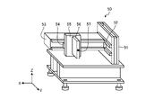
- FIG. 2 is a diagram showing an example of a positioning device to which the mechanism control system design method of Embodiment 1 is applied.
- FIG. 2 shows the X, Y and Z axes of a triaxial orthogonal coordinate system.
- the positioning device 50 shown in FIG. 2 has a pedestal 51, a beam 53, a head 55, and a head machine end 56 that constitute a mechanical system.
- the positioning device 50 also has a linear motor 52 for moving the beam 53 and a linear motor 54 for moving the head 55 .
- the beam 53 is provided movably in the Y-axis direction on the pedestal 51 .
- the head 55 is provided movably in the X-axis direction on the beam 53 .
- the positioning device 50 When the target position is specified, the positioning device 50 generates a position command so that the tip 57 of the machine end 56 of the head is aligned with the specified position.
- the positioning device 50 drives the linear motors 52 and 54 according to the position command to move the beam 53 and the head 55 so that the tip 57 coincides with the designated position.
- the user creates a Multi Body Dynamics (MBD) model of the positioning device 50, derives the following equation of motion (1) by the Kane method, and creates the mechanism model 21.
- MBD Multi Body Dynamics
- Equation (1) The left side of equation (1) is the inertia term.
- M(x) and h(x,x . ) include the mass, the inertia tensor, and the associated reference point , including the relative position vector up to .
- x is a variable representing displacement.
- the right side of Equation (1) represents the acting force acting on the mechanical system.
- the acting force includes thrust and frictional force.
- FIG. 3 is a diagram for explaining the vibration mode of the positioning device 50 shown in FIG.
- FEM analysis unit 13 appropriate fixing and contact conditions are set so that the natural frequency can be calculated by FEM analysis.
- the natural frequency of the pedestal 51 is separated from the natural frequencies of the beam 53 and the machine end 56 of the head. It is assumed that the coupling between the modes of the gantry 51 and the combination of the components other than the gantry 51 is minute, and that the motion of the gantry 51 has a minimal effect on the motion of the components other than the gantry 51. .
- the FEM analysis unit 13 determines the natural vibration 61 of the beam 53 around the Z axis from the FEM analysis result of the CAD model of the combination of the beam 53, the head 55, and the head mechanical end 56, which are components other than the base 51. , and a fixed frequency for the rotational vibration 62 of the head mechanical end 56 about the Z-axis.
- the FEM analysis unit 13 can reduce the amount of calculation while maintaining the analysis accuracy by omitting the motion of some components from the calculation.
- the calculation accuracy of the FEM analysis greatly affects the accuracy of the calculation results for the behavior of the mechanism control system.
- the results of FEM analysis will vary depending on the fixation and contact conditions of the FEM analysis. Therefore, in order to obtain highly accurate optimal design results for the mechanism control system, it is desired that highly accurate FEM analysis is possible by appropriately setting fixing and contact conditions. In order to improve the accuracy of FEM analysis, it is considered important to consider the fixing of parts by fastening fasteners.
- FIG. 4 is a diagram for explaining examples of fixing and contact conditions for FEM analysis in the mechanism control system design device 10 according to the first embodiment.
- fixation and contact conditions will be described using the structure 76 included in the structure to be analyzed as an example.
- the structure 76 has a hexagonal bolt 71 that is a fastener, a flat first part 72 and a columnar second part 73 .
- the hexagon bolt 71 has a head portion 71a and a body portion 71b.
- the first part 72 and the second part 73 are fixed to each other by fastening the hexagon bolts 71 .
- a body portion 71 b of the hexagon bolt 71 is passed through a hole 74 formed in the first part 72 and screwed into a hole 75 of the second part 73 .
- the first part 72 contacts the head 71 a of the hexagon bolt 71 .
- the second part 73 contacts the body 71b.
- Fixation and contact conditions include settings that indicate the fixed part, which is the part where parts are fixed to each other in the structure to be analyzed.
- each of the region 77, the inner wall surface of the hole 75, the surface of the head portion 71a that contacts the first component 72, and the surface of the body portion 71b that contacts the inner wall surface of the hole 75. is set in the fixed part.
- a region 77 is a region of the surface of the first component 72 that contacts the head portion 71 a and is an annular region surrounding the hole 74 .
- the diameter of the outer circle of the region 77 is equal to the width across flats of the hexagonal bolt 71 .
- the region 77 and the inner wall surface of the hole 75 are given a dot pattern.
- the FEM analysis unit 13 can perform a highly accurate structural analysis by reflecting such a manner of fixing the parts to each other in the FEM analysis.
- the mechanism system design parameter calculation unit 14 calculates the rigidity parameter and the damping parameter to obtain the rigidity parameter and the damping parameter when the mechanism dimension is changed. can be done.
- the mechanical system design parameter calculator 14 calculates the stiffness parameter KRz of the beam 53 shown in FIG. 2 around the Z-axis using the following equation (2).
- the mechanical system design parameter calculator 14 calculates the attenuation parameter CRz of the beam 53 around the Z-axis using the following equation (3).
- JB be the moment of inertia about the Z-axis at the coupling point of the beam 53 .
- F be the natural frequency of the rotational vibration 61 of the beam 53 about the Z-axis.
- the mechanical system design parameter calculation unit 14 acquires the natural frequency F from the analysis result by the FEM analysis unit 13 .
- ⁇ be a damping ratio determined so that the damping parameter CRz matches the measurement result of the damping parameter in the actual machine.
- the mechanical system design parameter calculation unit 14 calculates the rigidity parameter of the machine end 56 of the head around the Z-axis by using equation (2).
- the mechanism system design parameter calculator 14 calculates the damping parameter of the machine end 56 of the head around the Z-axis according to Equation (3).
- JB is the moment of inertia about the Z-axis at the coupling point of the head mechanical end 56 .
- F be the natural frequency of the rotational vibration 62 of the head mechanical end 56 about the Z-axis.
- the mechanism control system design device 10 uses the mechanism system design parameter calculator 14 to calculate the stiffness parameter and the damping parameter, which are mechanism system design parameters reflecting changes in the mechanism dimensions.
- the mechanism control system design device 10 can obtain mechanism system design parameters that reflect changes in mechanism dimensions, thereby realizing simultaneous optimum design of mechanism dimensions and control system design parameters.
- the above damping ratio is set so that the damping parameter of the structural element of the mechanical system when the structural element has a certain mechanical dimension matches the measurement result of the damping parameter of the actual machine.
- the mechanism control system behavior calculator 17 substitutes the mechanism system design parameters into the mechanism model 21 and substitutes the control system design parameters into the control model 22 . Thereby, the mechanism control system behavior calculator 17 calculates the behavior, which is the response result of the mechanism control system, based on the mechanism system design parameters and the control system design parameters.
- the control system design parameters are proportional gain, integral gain, derivative gain, and the like.
- the objective function calculation unit 18 calculates an objective function.
- the objective function of the positioning device 50 is defined such that the tip 57 converges to the designated position at high speed and residual vibration is reduced.
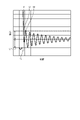
- FIG. 5 is a diagram for explaining the definition of the objective function calculated by the objective function calculator 18 of the mechanism control system design device 10 according to the first embodiment.
- a graph P shown in FIG. 5 represents the relationship between the position of the tip 57 and time. In FIG. 5, the vertical axis represents position and the horizontal axis represents time. Also, FIG. 5 shows a signal waveform C of the speed command. A signal waveform C shown in FIG. 5 is a waveform in which positive and negative are inverted. A double arrow shown in FIG. 5 represents the in-position width.
- a graph P represents an example in which an in-position crack occurs in the positioning device 50 . In-position cracking refers to tip 57 exiting the in-position width after tip 57 has once entered the in-position width.
- the positioning device 50 drives the linear motors 52, 54 according to the speed command to move the tip 57 to the designated position.
- the vibration of the tip 57 at the specified position converges over time.
- t1 is the timing when the output of the speed command is completed.
- t2 is the timing at which the tip 57 first enters the in-position width.
- t3 is the timing after t2 when the tip 57 leaves the in-position width and enters the in-position width again.
- t3 is the end point of the settling time. If there is no in-position crack, t2 is the end point of the settling time.
- t1 is the starting point of the settling time.
- the objective function of the positioning device 50 is defined by specifying a settling time, an integral of time multiplied by squared error (ITSE), an in-position width and an overshoot allowable width.
- the allowable overshoot width shall be less than half of the in-position width.
- ITSE is the integral of the value obtained by multiplying the squared value of the deviation by the time from the start of ITSE evaluation. Waveforms with poor attenuation have large ITSE values.
- w 1 , w 2 , w 3 , w 4 represent weighting factors.
- t start represents the timing at which ITSE evaluation is started.
- t end represents the timing of ending ITSE evaluation.
- t inp represents the timing at which the tip 57 first enters the in-position width.
- INP represents the in-position width.
- OS represents the allowable overshoot width.
- the simultaneous optimum design unit 19 performs optimization calculations to obtain mechanism dimensions and control system design parameters that minimize the objective function.
- the optimization calculation uses the method of steepest descent or a genetic algorithm.
- the mechanism control system designing device 10 determines the optimum mechanism dimensions and control system so that the tip end 57 converges at a specified position at high speed and residual vibration is reduced. It becomes possible to obtain the design parameters.
- the mechanism control system design device 10 calculates the stiffness parameter and the damping parameter in the mechanism system design parameter calculation unit 14, and thereby the simultaneous optimum design unit 19 calculates the relationship between the mechanism dimension and the control system design parameter. Simultaneous optimum design is possible.
- the mechanism control system design device 10 enables simultaneous optimum design of mechanism dimensions and control system design parameters instead of simultaneous optimum design of mechanism system design parameters and control system design parameters. , an optimized three-dimensional model of the mechanical system can be obtained.
- the mechanism control system design device 10 can realize the optimum design of the mechanism control system without searching for a three-dimensional model from the mechanism system design parameters.
- the mechanism control system design device 10 eliminates the need to search for a three-dimensional model from the mechanism system design parameters. can be reduced. As described above, the mechanism control system design device 10 has the effect of realizing the optimum design of the mechanism control system.
- FIG. 6 is a diagram showing the functional configuration of a mechanism control system design device 10a according to the second embodiment.
- the mechanism control system design device 10a has a response surface calculation unit 23 and a representative mechanism dimension setting unit 24 in addition to the same configuration as the mechanism control system design device 10 according to the first embodiment.
- the same reference numerals are assigned to the same components as in the first embodiment, and the configuration different from the first embodiment will be mainly described.
- the representative mechanism dimension setting unit 24 sets representative mechanism dimensions.
- the representative feature size is a feature size set in advance for structural analysis in the FEM analysis unit 13 .
- the CAD model changing unit 12 changes the mechanism dimensions shown in the CAD model to the set representative mechanism dimensions.
- the FEM analysis unit 13 performs FEM analysis on the analysis target of the representative mechanism dimensions, and outputs the FEM analysis results for the representative mechanism dimensions.
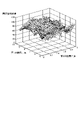
- FIG. 7 is a diagram showing an example of a response surface set in the response surface calculator 23 of the mechanism control system design device 10a according to the second embodiment.
- the vertical axis represents the response, which is the structural analysis result.
- the two axes perpendicular to the vertical axis represent the first feature dimension and the second feature dimension.
- the first feature size and the second feature size are feature sizes for different portions of the mechanical system.
- the FEM analysis results for each of a plurality of representative mechanism dimensions are input to the response surface calculation unit 23 .
- the response surface calculator 23 obtains a response surface for estimating the FEM analysis result for an arbitrary mechanism dimension using the input data group composed of the FEM analysis results.
- the response surface calculator 23 obtains a response surface by using Delaunay triangulation or the like.
- the response surface calculator 23 obtains a response surface for each element of the analysis result.
- a response surface for estimating a structural analysis result for an analysis target of arbitrary mechanism dimensions is set in advance in the response surface calculation unit 23 .
- the mechanism dimensions set by the mechanism dimension setting unit 11 are input to the response surface calculation unit 23 .
- the response surface calculator 23 estimates the FEM analysis result for the input mechanism dimensions using the response surface. That is, the response surface calculation unit 23 obtains the FEM analysis result for the analysis target of the input mechanism dimension based on the response surface.
- the FEM analysis results obtained by the response surface calculator 23 are input to the mechanical system design parameter calculator 14 .
- processing by components other than the CAD model changing unit 12, the FEM analysis unit 13, the response surface calculation unit 23, and the representative mechanism dimension setting unit 24 is the same as in the case of the first embodiment. is.
- the mechanism control system design device 10a repeats updating of mechanism dimensions and control system design parameters and optimization calculation of mechanism dimensions and control system design parameters to perform simultaneous optimal design of mechanism dimensions and control system design parameters.
- the response surface calculator 23 obtains the FEM analysis result based on the response surface set in advance, so that the FEM analysis can be omitted when the mechanism dimensions are updated. Therefore, the mechanism control system design device 10a can reduce the amount of calculation for simultaneous optimum design of mechanism dimensions and control system design parameters.
- FIG. 8 is a diagram showing the functional configuration of a mechanism control system design device 10b according to the third embodiment.
- the mechanism control system design device 10b has a mechanism dimension extraction unit 25 in addition to the same configuration as the mechanism control system design device 10 according to the first embodiment.
- the same reference numerals are assigned to the same constituent elements as in the first or second embodiment, and the configuration different from that in the first or second embodiment will be mainly described.
- the mechanism dimension extraction unit 25 extracts a mechanism dimension that causes a larger change in the behavior calculation result when the mechanism dimension is changed than when a mechanism dimension other than the mechanism dimension is changed is extracted from a plurality of mechanism dimensions in the mechanism system. Extract from inside.
- the mechanism dimension extraction unit 25 calculates the behavior of the mechanism control system by the mechanism control system behavior calculation unit 17 when the mechanism dimension is changed within the changeable range for each of the changeable mechanism dimensions. Extract the mechanism dimensions. In this way, the mechanism dimension extracting unit 25 determines the mechanism dimension to be changed for optimum design by extracting the mechanism dimension that causes a large change in the behavior calculation result with respect to the change in the mechanism dimension.
- the CAD model changing unit 12 changes the mechanism dimensions extracted by the mechanism dimension extracting unit 25 out of the mechanism dimensions shown in the CAD model.
- FIG. 9 is a diagram for explaining an example of applying the extraction of the mechanism dimensions according to the third embodiment to the design of the positioning device 50.
- a CAD model of beam 53, head 55 and head machine end 56 is shown in FIG.
- the beam 53 has a linear motor 52 , a Y-axis top plate 58 , ribs 59 and a beam tip 60 .
- the mechanism dimension extraction unit 25 selects a changeable mechanism dimension among the mechanism dimensions of these parts.
- the mechanism dimension extraction unit 25 changes the selected mechanism dimension within a changeable range, and acquires the calculation result of the behavior of the mechanism control system by the mechanism control system behavior calculation unit 17 .
- the mechanism dimension extraction unit 25 obtains the calculation result of the behavior when the mechanism dimension is changed for each of the changeable mechanism dimensions, and detects the mechanism whose behavior calculation result changes to a greater degree than the other mechanism dimensions. Ask for dimensions.
- the mechanism dimension extraction unit 25 extracts the thickness 66 of the Y-axis top plate 58 .
- the mechanism dimension setting unit 11 sets the post-change thickness 66 when updating the mechanism dimension.
- the CAD model changing unit 12 changes the thickness 66 of the mechanical dimensions shown in the CAD model.
- the mechanism dimension extracting unit 25 extracts the thickness 66, which is one mechanism dimension, from among a plurality of mechanism dimensions, but it is not limited to this. It is assumed that the number of mechanism dimensions extracted by the mechanism dimension extraction unit 25 is arbitrary.
- the processing by the components of the mechanism control system design device 10b other than the mechanism dimension extraction unit 25 is the same as in the case of the first embodiment.
- the mechanism control system design device 10b extracts a mechanism dimension that causes a larger change in the behavior calculation result when the mechanism dimension is changed than when other mechanism dimensions are changed, thereby determining the mechanism to be optimally designed. Limit the dimensions. As a result, the mechanism control system design device 10b can reduce the amount of calculation for simultaneous optimum design of mechanism dimensions and control system design parameters.
- FIG. 10 is a diagram showing the functional configuration of a mechanism control system design device 10c according to the fourth embodiment.
- the mechanism control system design device 10c has a degree of freedom reduction unit 26 in addition to the same configuration as the mechanism control system design device 10 according to the first embodiment.
- the same reference numerals are assigned to the same components as in the first to third embodiments, and the configuration different from the first to third embodiments will be mainly described.
- the mechanism model 21 with reduced degrees of freedom of the mechanism system is input to the degree of freedom reduction unit 26 from the outside of the mechanism control system design device 10c.
- the degree-of-freedom reduction unit 26 outputs the mechanism model 21 in which the degrees of freedom of the mechanism system are reduced to the mechanism control system behavior calculation unit 17 .
- the mechanism model 21 with reduced degrees of freedom of the mechanism system is set in the mechanism control system behavior calculator 17 .
- FIG. 11 shows a frame 51, a beam 53, a head 55, and a head machine end 56, which constitute the mechanical system of the positioning device 50. As shown in FIG. Each of cradle 51, beam 53, head 55 and head machine end 56 are rigid.
- Each rigid body has 3 degrees of freedom of translational motion due to translational motion in each of the X-axis direction, Y-axis direction, and Z-axis direction.
- Each rigid body has three degrees of freedom of rotational motion, with rotational motion about each of the X-axis, Y-axis, and Z-axis. Since each of the pedestal 51, the beam 53, the head 55 and the head machine end 56 has 6 degrees of freedom, the mechanical system of the positioning device 50 has 24 degrees of freedom.
- the vibration mode that affects the settling waveform is assumed to be the vibration mode shown in FIG.
- X-axis translational motion of the gantry 51 with respect to the ground on which the positioning device 50 is installed Y-axis translational motion of the gantry 51 with respect to the ground, yawing of the gantry 51 with respect to the ground about the Z-axis, and beam 53 with respect to the gantry 51 .
- Y-axis bending of beam 53 with respect to pedestal 51 X-axis translation of head 55 with respect to beam 53, and X-axis bending of head machine end 56 with respect to head 55.
- the motion of each rigid body of the positioning device 50 is represented by .
- the mechanical model 21 that expresses the motion of each rigid body with seven degrees of freedom of the mechanical system is obtained.
- the degree-of-freedom reduction unit 26 outputs the mechanism model 21 in which the degrees of freedom of the mechanism system are reduced to the mechanism control system behavior calculation unit 17 .
- the mechanism control system behavior calculator 17 calculates the behavior of the mechanism control system based on the mechanism model 21 in which the degrees of freedom of the mechanism system are reduced.
- the processing by the components of the mechanism control system design device 10c other than the degree of freedom reduction unit 26 is the same as in the case of the first embodiment.
- pedestal 51, beam 53, head 55, and head machine end 56 are represented as rigid 1, rigid 2, rigid 3, and rigid 4, respectively.
- ⁇ 1 represents a coordinate system fixed with the center of mass of the rigid body 1 as the origin.
- ⁇ 2 represents a coordinate system fixed with the center of mass of the rigid body 2 as the origin.
- ⁇ 3 represents a coordinate system fixed with the center of mass of the rigid body 3 as the origin.
- ⁇ 4 represents a coordinate system fixed with the center of mass of the rigid body 4 as the origin.
- ⁇ 0 represents a ground-fixed coordinate system.
- a coordinate system fixed to the rigid body i is defined at the connection point between a certain rigid body i and a rigid body k other than the rigid body i. Such a coordinate system is represented as ⁇ ik . Let i be any number from 1, 2, 3, and 4. Let k be any number among 1, 2, 3, and 4 and satisfy k ⁇ i.
- x 01 , y 01 , ⁇ z01 represent the displacement of rigid body 1 with respect to the ground.
- x 01 represents the displacement in the X-axis direction.
- y 01 represents the displacement in the Y-axis direction.
- ⁇ z01 represents the rotational displacement around the Z-axis.
- the reference for x 01 , y 01 , and ⁇ z01 is set to ⁇ 0 .
- y 12 , ⁇ z12 represent the relative displacement of rigid body 2 with respect to rigid body 1 .
- y12 represents the displacement in the Y-axis direction.
- ⁇ z12 represents the rotational displacement around the joint point between rigid bodies 1 and 2, which is the rotational displacement around the Z axis.
- ⁇ 12 is used as the reference for y 12 and ⁇ z12 .
- x23 represents the relative displacement of rigid body 3 with respect to rigid body 2; x23 represents the displacement in the X-axis direction.
- the reference for x23 is ⁇ 23 .
- ⁇ z34 represents the relative displacement of rigid body 4 with respect to rigid body 3; ⁇ z34 represents the rotational displacement around the joint point between the rigid bodies 3 and 4, which is the rotational displacement around the Z axis.
- the reference for ⁇ z34 is ⁇ 34 .
- the stiffness and damping of the mechanism model 21 are expressed by introducing springs representing translational or rotational motion and damping elements. be done.
- K Tx01 , K Ty01 , K Rz01 , K Rz12 , and K Rz34 represent stiffness.
- C Tx01 , C Ty01 , C Rz01 , C Rz12 , and C Rz34 represent attenuation constants.
- the mechanism control system design device 10c By reducing the degree of freedom based on the analysis result of the vibration mode of the mechanism system, the mechanism control system design device 10c provides the mechanism model 21 in which the degree of freedom of the mechanism system is reduced while maintaining the accuracy of the mechanism model 21. is set. By setting the mechanism model 21 with reduced degrees of freedom, the mechanism control system design device 10c can reduce the amount of calculation for simultaneous optimum design of mechanism dimensions and control system design parameters.
- FIG. 12 is a diagram showing a first configuration example of hardware that implements the mechanism control system design apparatuses 10, 10a, 10b, and 10c according to the first to fourth embodiments.
- a first configuration example is a configuration example in which a processing circuit 31 having a processor 33 and a memory 34 realizes each function of the mechanism control system design devices 10, 10a, 10b, and 10c.
- the processor 33 is a CPU (Central Processing Unit).
- the processor 33 may be an arithmetic unit, a processing unit, a microprocessor, a microcomputer, a DSP (Digital Signal Processor), or a system LSI (Large Scale Integration).
- the memory 34 is, for example, a non-volatile or Volatile semiconductor memory, magnetic disk, flexible disk, optical disk, compact disk, mini disk, DVD (Digital Versatile Disk), and the like.
- the memory 34 stores a mechanism control system design program that is a program for operating as the mechanism control system design devices 10, 10a, 10b, and 10c.
- the mechanism control system design devices 10, 10a, 10b, and 10c can be realized by the processor 33 reading and executing the mechanism control system design program. It can be said that the mechanism control system design program causes a computer to execute the procedures or methods of the mechanism control system design devices 10, 10a, 10b, and 10c.
- Mechanism dimension setting unit 11, CAD model change unit 12, FEM analysis unit 13, mechanism system design parameter calculation unit 14, mechanism system design parameter setting unit 15, control system design parameter setting unit 16, mechanism control system behavior calculation unit 17, purpose Function calculator 18 , simultaneous optimum design unit 19 , response surface calculator 23 , representative feature size setting unit 24 , and feature size extractor 25 are implemented by a combination of processor 33 and memory 34 .
- the memory 34 also stores information set in the mechanism control system design devices 10, 10a, 10b, and 10c.
- the memory 34 is also used as temporary memory when the processor 33 executes various processes.
- the mechanism control system design program stored in the memory 34 is written in a storage medium such as a CD (Compact Disc)-ROM, a DVD (Digital Versatile Disc)-ROM, etc., and provided to the user. or in a form provided via a network.
- a storage medium such as a CD (Compact Disc)-ROM, a DVD (Digital Versatile Disc)-ROM, etc.
- the input unit 32 is a circuit that receives input signals to the mechanism control system design devices 10, 10a, 10b, and 10c from the outside.
- the output unit 35 is a circuit that outputs signals generated by the mechanism control system design devices 10, 10a, 10b, and 10c to the outside of the mechanism control system design devices 10, 10a, 10b, and 10c.
- the optimum design result output section 20 is implemented by the output section 35 .
- the degree-of-freedom reduction unit 26 is realized by the input unit 32 .
- FIG. 12 shows an example of hardware when mechanism control system design devices 10, 10a, 10b, and 10c are realized by a general-purpose processor 33 and memory 34. Instead of the processor 33 and memory 34, a dedicated processing circuit is used. The mechanism control system design devices 10, 10a, 10b, and 10c may be realized.
- FIG. 13 is a diagram showing a second configuration example of hardware that implements the mechanism control system design apparatuses 10, 10a, 10b, and 10c according to the first to fourth embodiments.
- a second configuration example is a configuration example in which the functions of the mechanism control system design devices 10, 10a, 10b, and 10c are realized by a dedicated processing circuit 36.
- the processing circuit 36 is a single circuit, a composite circuit, an ASIC (Application Specific Integrated Circuit), an FPGA (Field Programmable Gate Array), or a circuit combining these.
- a part of the mechanism control system design devices 10, 10a, 10b, and 10c may be implemented by the processor 33 and the memory 34, and the rest may be implemented by a dedicated processing circuit .
- each embodiment is an example of the content of the present disclosure.
- the configuration of each embodiment can be combined with another known technique. Configurations of respective embodiments may be combined as appropriate. A part of the configuration of each embodiment can be omitted or changed without departing from the gist of the present disclosure.
- Mechanism control system design device 10a, 10b, 10c Mechanism control system design device, 11 Mechanism dimension setting unit, 12 CAD model change unit, 13 FEM analysis unit, 14 Mechanism design parameter calculation unit, 15 Mechanism design parameter setting unit, 16 Control system design Parameter setting unit 17 Mechanism control system behavior calculation unit 18 Objective function calculation unit 19 Simultaneous optimum design unit 20 Optimal design result output unit 21 Mechanism model 22 Control model 23 Response surface calculation unit 24 Representative mechanism dimension setting section, 25 mechanical dimension extraction section, 26 degree of freedom reduction section, 31, 36 processing circuit, 32 input section, 33 processor, 34 memory, 35 output section, 50 positioning device, 51 pedestal, 52, 54 linear motor, 53 beam, 55 head, 56 head machine end, 57 tip, 58 Y-axis top plate, 59 rib, 60 beam tip, 61, 62, 65 rotational vibration, 63, 64 translational vibration, 66 thickness, 71 hexagon bolt, 71a head, 71b trunk, 72 first part, 73 second part, 74, 75 hole, 76 structure, 77 area.
Landscapes
- Engineering & Computer Science (AREA)
- Physics & Mathematics (AREA)
- Theoretical Computer Science (AREA)
- Computer Hardware Design (AREA)
- Evolutionary Computation (AREA)
- Geometry (AREA)
- General Engineering & Computer Science (AREA)
- General Physics & Mathematics (AREA)
- Feedback Control In General (AREA)
Abstract
機構制御系設計装置(10)は、機構系の形状データに示される機構寸法を変更する形状変更部と、形状データにより表される機構系である解析対象の構造を解析する構造解析部と、解析対象の構造の解析結果に基づいて機構系の設計パラメータを計算する機構系設計パラメータ計算部(14)と、機構系の構成を表す機構モデル(21)へ機構系の設計パラメータを代入し、かつ制御系の構成を表す制御モデル(22)へ制御系の設計パラメータを代入することによって、機構制御系の挙動を計算する機構制御系挙動計算部(17)と、機構制御系の挙動の計算結果に基づいて機構制御系の目的関数を計算する目的関数計算部(18)と、目的関数を同時に最適化させる機構寸法および制御系の設計パラメータを求める同時最適設計部(19)と、を備える。
Description
本開示は、機構系および制御系からなる機構制御系を設計するための機構制御系設計装置および機構制御系設計方法に関する。
高精度な位置決めを要求される機構制御系の設計において、機構系のモデルと制御系のモデルとを組み合わせて、機構制御系の設計仕様を満足させる機構系の設計パラメータおよび制御系の設計パラメータを求める技術が知られている。特許文献1には、機構系および制御系を含む全体系のモデルを作成し、機構制御系の最適化を可能とする機構系設計パラメータおよび制御系設計パラメータを決定することによって機構系と制御系との同時最適設計を行う設計方法が開示されている。
また、構造解析の1つである有限要素法(Finite Element Method:FEM)による解析において、解析対象である機構系の寸法が変更された場合に、機構系の3次元モデルを自動的に変更して解析を行う技術が知られている。特許文献2には、解析対象の寸法変更に従って3次元モデルを変更し、あらかじめ設定された解析条件に従ってFEM解析を行う自動解析方法が開示されている。
特許文献1の設計方法では、機構系の運動方程式から作成される状態方程式の機構系設計パラメータが最適化される。状態方程式の機構系設計パラメータが最適化されても、例えば、質量を軽くしかつ剛性を高くするというように、実現が難しい設計結果が得られる場合がある。この場合、計算された機構系設計パラメータを満足する機構系を設計することが困難となるか、機構系の設計に多大な時間を要することによって、機構制御系の最適設計の実現が困難となる。
特許文献2の自動解析方法では、FEM解析の結果から、あらかじめ設定された目的関数を満足する機構寸法を決定し得る。その一方で、特許文献2の自動解析方法では、制御系については考慮されないため、機構系と制御系との同時最適設計を行うことができない。以上のように、特許文献1または特許文献2にかかる従来技術によると、機構制御系の最適設計を実現することが困難であった。
本開示は、上記に鑑みてなされたものであって、機構制御系の最適設計を実現可能とする機構制御系設計装置を得ることを目的とする。
上述した課題を解決し、目的を達成するために、本開示にかかる機構制御系設計装置は、機構系および制御系からなる機構制御系を設計するための機構制御系設計装置である。本開示にかかる機構制御系設計装置は、機構系の形状データに示される機構寸法を変更する形状変更部と、形状データにより表される機構系である解析対象の構造を解析する構造解析部と、解析対象の構造の解析結果に基づいて機構系の設計パラメータを計算する機構系設計パラメータ計算部と、機構系の構成を表す機構モデルへ機構系の設計パラメータを代入し、かつ制御系の構成を表す制御モデルへ制御系の設計パラメータを代入することによって、機構制御系の挙動を計算する機構制御系挙動計算部と、機構制御系の挙動の計算結果に基づいて機構制御系の目的関数を計算する目的関数計算部と、目的関数を同時に最適化させる機構寸法および制御系の設計パラメータを求める同時最適設計部と、を備える。
本開示にかかる機構制御系設計装置は、機構制御系の最適設計の実現が可能となるという効果を奏する。
以下に、実施の形態にかかる機構制御系設計装置および機構制御系設計方法を図面に基づいて詳細に説明する。
実施の形態1.
図1は、実施の形態1にかかる機構制御系設計装置10の機能構成を示す図である。機構制御系設計装置10は、機構系および制御系からなる機構制御系を設計するための計算を行う。機構制御系は、位置決め装置またはロボットマニピュレータといった、高精度な位置決めを要求される装置に適用される。
図1は、実施の形態1にかかる機構制御系設計装置10の機能構成を示す図である。機構制御系設計装置10は、機構系および制御系からなる機構制御系を設計するための計算を行う。機構制御系は、位置決め装置またはロボットマニピュレータといった、高精度な位置決めを要求される装置に適用される。
機構制御系設計装置10は、機構寸法を設定する機構寸法設定部11と、機構系の3次元モデルであるCAD(Computer-Aided Design)モデルを変更するCADモデル変更部12と、FEMにより機構系の構造を解析するFEM解析部13と、機構系の設計パラメータを計算する機構系設計パラメータ計算部14と、機構系の設計パラメータを設定する機構系設計パラメータ設定部15と、制御系の設計パラメータを設定する制御系設計パラメータ設定部16と、を有する。以下、機構系の設計パラメータを機構系設計パラメータと称する。制御系の設計パラメータを制御系設計パラメータと称する。
また、機構制御系設計装置10は、機構制御系の挙動を計算する機構制御系挙動計算部17と、機構制御系の目的関数を計算する目的関数計算部18と、最適設計結果を求める同時最適設計部19と、最適設計結果を出力する最適設計結果出力部20とを有する。図1に示す白抜き矢印は、機構制御系設計装置10の各部による処理の手順を表す。
機構寸法設定部11により設定された機構寸法は、CADモデル変更部12へ入力される。形状変更部であるCADモデル変更部12は、入力された機構寸法に従って、機構系の形状データであるCADモデルを変更する。CADモデル変更部12は、あらかじめ設定されたCADモデルを変更する。
CADモデル変更部12によって変更されたCADモデルは、FEM解析部13へ入力される。構造解析部であるFEM解析部13は、CADモデルにより表される機構系である解析対象の構造を解析する。FEM解析部13は、解析対象についての、固有振動数、ひずみ、質量、重心位置、および慣性テンソル等といった要素ごとの解析結果を出力する。FEM解析部13は、CADモデル変更部12において変更されたCADモデルに、あらかじめ設定された解析条件に従って解析処理を実行する。解析条件は、固定および接触条件と、荷重条件とを含む。固定および接触条件は、解析対象の構造における部品同士の接触および固定の態様を示す条件とする。
FEM解析部13による解析結果は、機構系設計パラメータ計算部14へ入力される。機構系設計パラメータ計算部14は、解析対象の構造の解析結果に基づいて機構系設計パラメータを計算する。機構系設計パラメータ計算部14によって計算される機構系設計パラメータは、機構系の構成要素の剛性パラメータと機構系の構成要素の減衰パラメータとを含む。機構系設計パラメータ計算部14は、固有振動数、ひずみ、および機構寸法の少なくとも1つに基づいて、剛性パラメータおよび減衰パラメータを求める。計算された機構系設計パラメータは、機構系設計パラメータ設定部15へ入力される。
機構モデル21は、機構系の構成を表すモデルであって、機構系の機械動特性を数学モデル化したものである。機構モデル21は、質点系モデルまたは伝達関数モデルを含む。一例として、機構モデル21は、機構制御系設計装置10のユーザが機構系における剛体数および対偶等を決定することによって求まる。設定された機構モデル21を用いて、機構系の解析処理と制御系の解析処理との各々について機構系の運動方程式が設定される。機構モデル21では、設定された運動方程式と機構系設計パラメータとに基づいて、機構系に推力が与えられた際における、機構系の所望の制御変数が計算される。制御変数は、機構系のうち制御系によって制御される可動部の位置または速度を表す変数である。計算された制御変数の値は、機構モデル21から出力される。
制御モデル22は、制御系の構成を表すモデルである。制御モデル22では、機構モデル21から入力された制御変数の値と制御系設計パラメータとに基づいて、機構系の駆動に必要な推力が計算される。計算された推力の値は、制御モデル22から出力される。機構モデル21の出力が、制御モデル22への入力となる。制御モデル22の出力が、機構モデル21への入力となる。機構モデル21および制御モデル22は、あらかじめ機構制御系挙動計算部17に設定される。
機構制御系挙動計算部17には、機構系設計パラメータ設定部15からの機構系設計パラメータと、制御系設計パラメータ設定部16からの制御系設計パラメータとが入力される。機構制御系挙動計算部17は、機構系の解析処理と制御系の解析処理とを実行する。機構制御系挙動計算部17は、機構制御系に任意の位置指令または任意の速度指令が与えられた際における機械端の挙動、すなわち機構制御系の挙動を計算する。機構制御系挙動計算部17は、機構モデル21へ機構系設計パラメータを代入し、かつ制御モデル22へ制御系設計パラメータを代入することによって、機構制御系の挙動を計算する。機構制御系挙動計算部17は、機構系の解析処理と制御系の解析処理との各々において機構モデル21から書き出される運動方程式に基づいて、機構制御系の挙動を計算する。
機構系の解析処理において、機構制御系挙動計算部17は、運動方程式に基づいて、機構系の位置または速度と推力とから加速度を計算する。また、機構制御系挙動計算部17は、加速度の計算結果を基に、次の制御周期における位置または速度を計算する。制御系の解析処理において、機構制御系挙動計算部17は、位置指令と実際の位置との差分または速度指令と実際の速度との差分から、機構系に入力される推力を計算するフィードバック制御を行う。または、機構制御系挙動計算部17は、位置指令と実際の位置との差分または速度指令と実際の速度との差分を少なくするために必要な推力を運動方程式に基づいてあらかじめ計算するフィードフォワード制御を行う。このようにして、機構制御系挙動計算部17は、機構制御系の挙動を計算する。機構制御系挙動計算部17は、機構制御系の挙動の計算結果を出力する。
機構制御系の挙動の計算結果は、目的関数計算部18へ入力される。目的関数計算部18は、機構制御系の挙動の計算結果に基づいて目的関数を計算する。目的関数計算部18は、目的関数を計算することによって、あらかじめ設定された評価方法に基づいて機構制御系の挙動を評価する。
目的関数計算部18によって計算された目的関数は、同時最適設計部19へ入力される。同時最適設計部19は、目的関数を同時に最適化させる機構寸法および制御系設計パラメータを求める。同時最適設計部19は、あらかじめ設定された最適化手法に基づいて、目的関数が最小になるように、機構寸法と制御系設計パラメータとを更新する。機構寸法設定部11は、更新された機構寸法を設定する。制御系設計パラメータ設定部16は、更新された制御系設計パラメータを設定する。
同時最適設計部19は、機構寸法と制御系設計パラメータとの更新が終了してから、最適設計結果である機構寸法および制御系設計パラメータを最適設計結果出力部20へ出力する。最適設計結果出力部20は、最適設計結果である機構寸法および制御系設計パラメータを機構制御系設計装置10の外部へ出力する。以上により、機構制御系設計装置10は、機構制御系の設計のための処理を終了する。
機構制御系設計装置10は、機構寸法および制御系設計パラメータの最適設計を可能としたことで、機構系を設計可能な3次元モデルを最適設計結果から得るとともに、機構系と制御系との最適設計を実現可能である。機構制御系設計装置10は、機構系設計パラメータ計算部14によって剛性パラメータおよび減衰パラメータが計算されることで、機構寸法と制御系設計パラメータとの同時最適化が可能となる。機構制御系設計装置10は、最適化された機構系設計パラメータから機構系の3次元モデルを探索する必要が無くなる。機構制御系設計装置10は、最適設計結果を基に3次元モデルを設計することが困難になるといった事態を回避できることによって、機構制御系の最適設計の実現が可能となる。また、機構制御系設計装置10は、機構系設計パラメータから3次元モデルを探索する必要が無くなることによって、機構制御系の最適設計に要する時間の短縮化と、機構制御系の最適設計に要する設計コストの削減とが可能となる。
次に、実施の形態1の機構制御系設計方法を位置決め装置の機構制御系の設計に適用する例について説明する。図2は、実施の形態1の機構制御系設計方法が設計に適用される位置決め装置の例を示す図である。図2には、3軸直交座標系のX軸、Y軸およびZ軸を示す。
図2に示す位置決め装置50は、機構系を構成する架台51、ビーム53、ヘッド55およびヘッド機械端56を有する。また、位置決め装置50は、ビーム53を移動させるリニアモータ52と、ヘッド55を移動させるリニアモータ54とを有する。ビーム53は、架台51においてY軸方向へ移動可能に設けられている。ヘッド55は、ビーム53においてX軸方向へ移動可能に設けられている。
位置決め装置50は、目標とする位置が指定されると、指定された位置にヘッド機械端56の先端57を一致させるように位置指令を生成する。位置決め装置50は、位置指令に従ってリニアモータ52,54を駆動することによって、指定された位置に先端57が一致するようにビーム53およびヘッド55を移動させる。
ユーザは、位置決め装置50のマルチボディダイナミクス(Multi Body Dynamics:MBD)モデルを作成し、次の式(1)の運動方程式をケイン法によって導出し、機構モデル21を作成する。

式(1)の左辺は慣性項である。M(x)およびh(x,x・)には、架台51、ビーム53、ヘッド55およびヘッド機械端56の各々である剛体についての、質量と、慣性テンソルと、質量中心から当該結合基準点までの相対位置ベクトルとを含む。xは、変位を表す変数である。式(1)の右辺は、機構系に作用する作用力を表す。作用力は、推力と摩擦力とを含む。
位置決め装置50についての機構制御系の挙動の計算においては、実機の挙動を数ミクロンオーダーで一致するような精度が求められる。機構制御系の挙動の計算において伝達関数モデルが使用された場合、伝達関数の与えられる係数が実機における何を示しているのかといった、伝達関数モデルと実機との関係性を理解することが困難となる場合がある。これに対し、MBDモデルでは、物理的なパラメータを使用しているため、慣性特性を実機に合わせ込むことによってモデルの高精度化が容易となる。さらに、MBDモデルが使用されると、非線形性に対応することも可能となる。また、ケイン法によって運動方程式を導出することで、ニュートンオイラー法により運動方程式を導出する場合に比べて、各剛体間の拘束力を計算する必要が無くなり計算量の削減が可能となる。
図3は、図2に示す位置決め装置50の振動モードについて説明するための図である。FEM解析部13では、FEM解析によって固有振動数を計算可能に、適当な固定および接触条件が設定される。
ここで、モード解析結果から、架台51の固有振動数が、ビーム53およびヘッド機械端56の各固有振動数とは離れていることが判明しているとする。架台51と、架台51以外の構成要素の組み合わせとのモード間の連成が微小であって、架台51の運動が、架台51以外の構成要素の運動に及ぼす影響が微小であるものと仮定する。
ビーム53のZ軸周りの回転振動61についての固有振動数と、ヘッド機械端56のZ軸周りの回転振動62についての固定振動数とを求める場合、架台51のX軸方向の並進振動63、架台51のY軸方向の並進振動64、および架台51のZ軸周りの回転振動65は無視される。FEM解析部13は、架台51以外の構成要素であるビーム53、ヘッド55およびヘッド機械端56の組み合わせのCADモデルについてのFEM解析結果から、ビーム53のZ軸周りの回転振動61についての固有振動数と、ヘッド機械端56のZ軸周りの回転振動62についての固定振動数とを求める。FEM解析部13は、一部の構成要素の運動については計算から省くことによって、解析精度を維持しながら計算量を削減することができる。
FEM解析の計算精度は、機構制御系の挙動についての計算結果の精度に大きく影響する。FEM解析の結果は、FEM解析の固定および接触条件によって変化する。したがって、機構制御系について高精度な最適設計結果を得るためには、固定および接触条件が適切に設定されることによって高精度なFEM解析が可能であることが望まれる。FEM解析の精度向上には、固着具の締結による部品同士の固定について考慮することが重要と考えられる。
図4は、実施の形態1にかかる機構制御系設計装置10におけるFEM解析の固定および接触条件の例について説明するための図である。ここでは、解析対象の構造に含まれる構造体76を例として、固定および接触条件について説明する。
構造体76は、固着具である六角ボルト71と、平板である第1の部品72と、柱状の第2の部品73とを有する。六角ボルト71は、頭部71aと胴部71bとを有する。第1の部品72と第2の部品73とは、六角ボルト71の締結によって互いに固定される。六角ボルト71の胴部71bは、第1の部品72に形成された孔74を通されて、第2の部品73の孔75にねじ込まれる。第1の部品72は、六角ボルト71の頭部71aに接触する。第2の部品73は、胴部71bに接触する。
固定および接触条件には、解析対象の構造において部品同士が固定される部分である固定部を示す設定が含まれる。構造体76については、領域77と、孔75の内壁面と、頭部71aのうち第1の部品72に接触する面と、胴部71bのうち孔75の内壁面に接触する面との各々が、固定部に設定される。領域77は、第1の部品72のうち頭部71aに接触する面における領域であって、孔74を囲う環状の領域である。領域77のうち外側の円の直径は、六角ボルト71の二面幅に等しい。図4では、領域77と孔75の内壁面とにドット模様を付している。FEM解析部13は、このような部品同士の固定の態様をFEM解析に反映させることによって、高精度な構造解析を行うことが可能となる。
機構寸法が変更されると、質量と、質量中心と、慣性テンソルと、剛性パラメータと、減衰パラメータとの各々が変化する。剛性パラメータと減衰パラメータとは、FEM解析結果から直接得ることができない。実施の形態1にかかる機構制御系設計装置10は、機構系設計パラメータ計算部14が剛性パラメータと減衰パラメータとを計算することによって、機構寸法が変更された場合における剛性パラメータおよび減衰パラメータを得ることができる。
ここで、機構系設計パラメータ計算部14による剛性パラメータと減衰パラメータとの計算例を説明する。機構系設計パラメータ計算部14は、図2に示すビーム53のZ軸周りの剛性パラメータKRzを、次の式(2)により計算する。機構系設計パラメータ計算部14は、ビーム53のZ軸周りの減衰パラメータCRzを、次の式(3)により計算する。JBは、ビーム53の結合点におけるZ軸周りの慣性モーメントとする。Fは、ビーム53のZ軸周りの回転振動61についての固有振動数とする。機構系設計パラメータ計算部14は、FEM解析部13による解析結果から固有振動数Fを取得する。ζは、減衰パラメータCRzが実機における減衰パラメータの計測結果と一致するように決定された減衰比とする。


機構系設計パラメータ計算部14は、式(2)により、ヘッド機械端56のZ軸周りの剛性パラメータを計算する。機構系設計パラメータ計算部14は、式(3)により、ヘッド機械端56のZ軸周りの減衰パラメータを計算する。この場合、JBは、ヘッド機械端56の結合点におけるZ軸周りの慣性モーメントとする。Fは、ヘッド機械端56のZ軸周りの回転振動62についての固有振動数とする。
このように、機構制御系設計装置10は、機構寸法の変更が反映された機構系設計パラメータである剛性パラメータおよび減衰パラメータを、機構系設計パラメータ計算部14によって計算する。機構制御系設計装置10は、機構寸法の変更が反映された機構系設計パラメータを求めることができることによって、機構寸法と制御系設計パラメータとの同時最適設計の実現が可能となる。
上記の減衰比は、機構系の構成要素の寸法がある機構寸法であるときにおける当該構成要素の減衰パラメータが、実機での減衰パラメータの計測結果に一致するように設定される。機構寸法の変更が反映された減衰パラメータを機構系設計パラメータ計算部14において計算可能であることによって、機構制御系設計装置10は、機構制御系挙動計算部17において、機構制御系の挙動を高精度に計算することが可能となる。
機構制御系挙動計算部17は、機構モデル21へ機構系設計パラメータを代入し、かつ制御モデル22へ制御系設計パラメータを代入する。これにより、機構制御系挙動計算部17は、機構系設計パラメータと制御系設計パラメータとに基づいて、機構制御系の応答結果である挙動を計算する。制御系設計パラメータは、比例ゲイン、積分ゲインおよび微分ゲイン等である。
目的関数計算部18は、目的関数を計算する。位置決め装置50の目的関数は、指定された位置に先端57を高速に収束させ、かつ残留振動が少なくなるように定義される。
図5は、実施の形態1にかかる機構制御系設計装置10の目的関数計算部18によって計算される目的関数の定義について説明するための図である。図5に示すグラフPは、先端57の位置と時間との関係を表す。図5において、縦軸は位置、横軸は時間を表す。また、図5には、速度指令の信号波形Cを示す。図5に示す信号波形Cは、正負を反転させた波形である。図5に示す両矢印は、インポジション幅を表す。グラフPは、位置決め装置50のインポジション割れが生じた場合の例を表す。インポジション割れは、インポジション幅内に先端57が一旦入った後に先端57がインポジション幅から出ることを指す。
位置決め装置50は、速度指令に従ってリニアモータ52,54を駆動することによって、指定された位置へ先端57を移動させる。指定された位置における先端57の振動は、時間の経過に従って収束する。t1は、速度指令の払い出しが終了したタイミングである。t2は、インポジション幅内に先端57が最初に入ったタイミングである。t3は、t2よりも後において先端57がインポジション幅から出て、インポジション幅内に再び先端57が入ったタイミングである。図5に示す例では、t3は、整定時間の終点である。インポジション割れが無ければt2が整定時間の終点となる。t1は、整定時間の始点である。
位置決め装置50の目的関数は、整定時間、時間荷重偏差2乗積分(Integral of Time multiplied by Squared Error:ITSE)、インポジション幅およびオーバーシュート許容幅を指定することによって定義される。オーバーシュート許容幅は、インポジション幅の半分以下とする。位置決め装置50では、整定時間は短いほど良い。ITSEは、偏差の2乗値に、ITSEの評価を開始したタイミングからの時間を乗じた値の積分である。減衰が悪い場合における波形では、ITSEの値が大きくなる。位置決め装置50は、インポジション割れが生じた場合、インポジション割れが判定された後に次の位置決め動作を行う。インポジション割れによって、次の位置決め動作開始のタイミングに影響が及ぶことから、位置決め装置50では、インポジション割れは生じないことが望ましい。
次の式(4)-(7)は、以上の内容を踏まえて定義された目的関数の例を示す。w1,w2,w3,w4は、重み係数を表す。tstartは、ITSEの評価を開始したタイミングを表す。tendは、ITSEの評価を終了するタイミングを表す。tinpは、インポジション幅内に先端57が最初に入ったタイミングを表す。INPは、インポジション幅を表す。OSは、オーバーシュート許容幅を表す。


同時最適設計部19は、目的関数が最小となる機構寸法と制御系設計パラメータとを求めるための最適化計算を行う。最適化計算には、最急降下法または遺伝的アルゴリズムが使用される。機構制御系設計装置10は、上記のように目的関数が定義されることによって、指定された位置に先端57を高速に収束させ、かつ残留振動が少なくなるように最適された機構寸法と制御系設計パラメータとを求めることが可能となる。
実施の形態1によると、機構制御系設計装置10は、機構系設計パラメータ計算部14において剛性パラメータと減衰パラメータとを計算することによって、同時最適設計部19における機構寸法と制御系設計パラメータとの同時最適設計を可能とする。機構制御系設計装置10は、機構系設計パラメータおよび制御系設計パラメータの同時最適設計ではなく、機構寸法および制御系設計パラメータの同時最適設計を可能としたことで、最適化された機構寸法を基に、機構系の最適化された3次元モデルを求めることができる。機構制御系設計装置10は、機構系設計パラメータから3次元モデルを探索すること無く、機構制御系の最適設計を実現することができる。機構制御系設計装置10は、機構系設計パラメータからの3次元モデルの探索が不要となることによって、機構制御系の最適設計に要する時間の短縮化と、機構制御系の最適設計に要する設計コストの削減とが可能となる。以上により、機構制御系設計装置10は、機構制御系の最適設計の実現が可能となるという効果を奏する。
実施の形態2.
図6は、実施の形態2にかかる機構制御系設計装置10aの機能構成を示す図である。機構制御系設計装置10aは、実施の形態1にかかる機構制御系設計装置10と同様の構成に加えて、応答曲面計算部23と代表機構寸法設定部24とを有する。実施の形態2では、上記の実施の形態1と同一の構成要素には同一の符号を付し、実施の形態1とは異なる構成について主に説明する。
図6は、実施の形態2にかかる機構制御系設計装置10aの機能構成を示す図である。機構制御系設計装置10aは、実施の形態1にかかる機構制御系設計装置10と同様の構成に加えて、応答曲面計算部23と代表機構寸法設定部24とを有する。実施の形態2では、上記の実施の形態1と同一の構成要素には同一の符号を付し、実施の形態1とは異なる構成について主に説明する。
代表機構寸法設定部24は、代表機構寸法を設定する。代表機構寸法は、FEM解析部13における構造解析のためにあらかじめ設定される機構寸法である。CADモデル変更部12は、CADモデルに示される機構寸法を、設定された代表機構寸法に変更する。FEM解析部13は、代表機構寸法の解析対象についてのFEM解析を行い、代表機構寸法におけるFEM解析結果を出力する。
図7は、実施の形態2にかかる機構制御系設計装置10aの応答曲面計算部23に設定される応答曲面の例を示す図である。図7において、上下方向の軸は、構造解析結果である応答を表す。上下方向の軸に垂直な2つの軸は、第1の機構寸法および第2の機構寸法を表す。第1の機構寸法および第2の機構寸法は、機構系における互いに異なる部分についての機構寸法である。
応答曲面計算部23には、複数の代表機構寸法の各々についてのFEM解析結果が入力される。応答曲面計算部23は、入力されたFEM解析結果からなるデータ群を用いて、任意の機構寸法についてのFEM解析結果を推定するための応答曲面を求める。応答曲面計算部23は、Delaunay三角形分割の使用等によって応答曲面を求める。応答曲面計算部23は、解析結果の要素ごとに応答曲面を求める。これにより、応答曲面計算部23には、任意の機構寸法の解析対象について構造の解析結果を推定するための応答曲面があらかじめ設定される。
応答曲面計算部23には、機構寸法設定部11により設定された機構寸法が入力される。応答曲面計算部23は、入力された機構寸法についてのFEM解析結果を、応答曲面を用いて推定する。すなわち、応答曲面計算部23は、入力された機構寸法の解析対象についてのFEM解析結果を応答曲面に基づいて求める。応答曲面計算部23によって得られたFEM解析結果は、機構系設計パラメータ計算部14へ入力される。機構制御系設計装置10aのうち、CADモデル変更部12、FEM解析部13、応答曲面計算部23、および代表機構寸法設定部24以外の構成要素による処理については、実施の形態1の場合と同様である。
機構制御系設計装置10aは、機構寸法および制御系設計パラメータの更新と、機構寸法および制御系設計パラメータの最適化計算とを繰り返して、機構寸法と制御系設計パラメータとの同時最適設計を行う。機構制御系設計装置10aは、応答曲面計算部23において、あらかじめ設定された応答曲面に基づいてFEM解析結果を求めることによって、機構寸法が更新された際におけるFEM解析を省くことができる。このため、機構制御系設計装置10aは、機構寸法と制御系設計パラメータとの同時最適設計のための計算量を削減することが可能となる。
実施の形態3.
図8は、実施の形態3にかかる機構制御系設計装置10bの機能構成を示す図である。機構制御系設計装置10bは、実施の形態1にかかる機構制御系設計装置10と同様の構成に加えて、機構寸法抽出部25を有する。実施の形態3では、上記の実施の形態1または2と同一の構成要素には同一の符号を付し、実施の形態1または2とは異なる構成について主に説明する。
図8は、実施の形態3にかかる機構制御系設計装置10bの機能構成を示す図である。機構制御系設計装置10bは、実施の形態1にかかる機構制御系設計装置10と同様の構成に加えて、機構寸法抽出部25を有する。実施の形態3では、上記の実施の形態1または2と同一の構成要素には同一の符号を付し、実施の形態1または2とは異なる構成について主に説明する。
機構寸法抽出部25は、機構寸法を変更した場合における挙動の計算結果の変化が、当該機構寸法以外の機構寸法を変更した場合に比べて大きくなる機構寸法を、機構系における複数の機構寸法の中から抽出する。機構寸法抽出部25は、変更可能な機構寸法の各々について変更可能な範囲内で機構寸法を変更させた場合における、機構制御系挙動計算部17による機構制御系の挙動の計算結果を基に、機構寸法を抽出する。このように、機構寸法抽出部25は、機構寸法の変更に対して挙動の計算結果の変化が大きくなる機構寸法を抽出することによって、最適設計のための変更対象とする機構寸法を決定する。CADモデル変更部12は、CADモデルに示される機構寸法のうち、機構寸法抽出部25によって抽出された機構寸法を変更する。
次に、実施の形態3による機構寸法の抽出を位置決め装置50の設計に適用する例について説明する。図9は、実施の形態3による機構寸法の抽出を位置決め装置50の設計に適用する例について説明するための図である。図9には、ビーム53、ヘッド55およびヘッド機械端56のCADモデルを示す。
ビーム53は、リニアモータ52と、Y軸天板58と、リブ59と、ビーム先端60とを有する。ここでは、ビーム53を構成するこれらの部品の各機構寸法の中から機構寸法を抽出する例を説明する。機構寸法抽出部25は、これらの部品の各機構寸法のうち、変更可能な機構寸法を選定する。また、機構寸法抽出部25は、選定された機構寸法を、変更可能な範囲で変化させるとともに、機構制御系挙動計算部17による機構制御系の挙動の計算結果を取得する。機構寸法抽出部25は、変更可能な機構寸法の各々について、機構寸法を変化させた場合における挙動の計算結果を求め、挙動の計算結果の変化の度合いが他の機構寸法に比べて大きくなる機構寸法を求める。
例えば、Y軸天板58の厚さ66を変更した場合に、他の機構寸法を変更した場合よりも挙動の計算結果の変化が大きかったとする。この場合、機構寸法抽出部25は、Y軸天板58の厚さ66を抽出する。機構寸法設定部11は、機構寸法の更新の際に、変更後の厚さ66を設定する。CADモデル変更部12は、CADモデルに示される機構寸法のうち厚さ66を変更する。ここでは、機構寸法抽出部25が、1つの機構寸法である厚さ66を複数の機構寸法の中から抽出することとしたが、これに限定されない。機構寸法抽出部25によって抽出される機構寸法の数は、任意であるものとする。機構制御系設計装置10bのうち機構寸法抽出部25以外の構成要素による処理については、実施の形態1の場合と同様である。
機構制御系設計装置10bは、機構寸法を変更した場合における挙動の計算結果の変化が他の機構寸法を変更した場合に比べて大きくなる機構寸法を抽出することによって、最適設計の対象とする機構寸法を限定させる。これにより、機構制御系設計装置10bは、機構寸法と制御系設計パラメータとの同時最適設計のための計算量を削減することが可能となる。
実施の形態4.
図10は、実施の形態4にかかる機構制御系設計装置10cの機能構成を示す図である。機構制御系設計装置10cは、実施の形態1にかかる機構制御系設計装置10と同様の構成に加えて、自由度縮退部26を有する。実施の形態4では、上記の実施の形態1から3と同一の構成要素には同一の符号を付し、実施の形態1から3とは異なる構成について主に説明する。
図10は、実施の形態4にかかる機構制御系設計装置10cの機能構成を示す図である。機構制御系設計装置10cは、実施の形態1にかかる機構制御系設計装置10と同様の構成に加えて、自由度縮退部26を有する。実施の形態4では、上記の実施の形態1から3と同一の構成要素には同一の符号を付し、実施の形態1から3とは異なる構成について主に説明する。
自由度縮退部26には、機構制御系設計装置10cの外部から、機構系の自由度を縮退させた機構モデル21が入力される。自由度縮退部26は、機構系の自由度を縮退させた機構モデル21を機構制御系挙動計算部17へ出力する。これにより、機構制御系挙動計算部17には、機構系の自由度を縮退させた機構モデル21が設定される。
次に、実施の形態4による自由度の縮退を位置決め装置50の設計に適用する例について説明する。図11は、実施の形態4による自由度の縮退を位置決め装置50の設計に適用する例について説明するための図である。図11には、位置決め装置50の機構系を構成する架台51、ビーム53、ヘッド55およびヘッド機械端56を示す。架台51、ビーム53、ヘッド55およびヘッド機械端56の各々は、剛体である。
X軸方向、Y軸方向およびZ軸方向の各々における並進運動により、各剛体の並進運動の自由度は3である。X軸方向周り、Y軸方向周りおよびZ軸方向周りの各々における回転運動により、各剛体の回転運動の自由度は3である。架台51、ビーム53、ヘッド55およびヘッド機械端56の各々の自由度が6であることから、位置決め装置50の機構系の自由度は24である。
位置決め装置50の機構系の振動モード解析の結果と、位置決め装置50の整定波形の周波数とを基に、整定波形に影響を及ぼす振動モードを、図3に示した振動モードと仮定したとする。位置決め装置50が設置されるグラウンドに対する架台51のX軸方向の並進運動と、グラウンドに対する架台51のY軸方向の並進運動と、グラウンドに対する架台51のZ軸周りのヨーイングと、架台51に対するビーム53のY軸方向の並進運動と、架台51に対するビーム53のY軸方向の曲げと、ビーム53に対するヘッド55のX軸方向の並進運動と、ヘッド55に対するヘッド機械端56のX軸方向の曲げとによって、位置決め装置50の各剛体の運動が表現される。
このようにして、整定波形に影響を及ぼす振動モードを解析した結果から、機構系の自由度を7として、各剛体の運動を表現する機構モデル21が求まる。自由度縮退部26は、機構系の自由度を縮退させた機構モデル21を機構制御系挙動計算部17へ出力する。機構制御系挙動計算部17は、機構系の自由度を縮退させた機構モデル21を基に、機構制御系の挙動を計算する。機構制御系設計装置10cのうち自由度縮退部26以外の構成要素による処理については、実施の形態1の場合と同様である。
ここで、架台51、ビーム53、ヘッド55およびヘッド機械端56を、それぞれ剛体1、剛体2、剛体3、剛体4と表す。Σ1は、剛体1の質量中心を原点として固定された座標系を表す。Σ2は、剛体2の質量中心を原点として固定された座標系を表す。Σ3は、剛体3の質量中心を原点として固定された座標系を表す。Σ4は、剛体4の質量中心を原点として固定された座標系を表す。Σ0は、グラウンドに固定された座標系を表す。また、ある剛体iと、剛体i以外の剛体kとの結合点には、剛体iに固定された座標系が定義される。かかる座標系を、Σikと表す。iは、1,2,3,4のうちの任意の数とする。kは、1,2,3,4のうちの任意の数であって、かつk≠iを満足する数とする。
機構系の運動における上記7個の自由度の各々についての回転を、3-2-1オイラー角により定義する。x01,y01,θz01は、グラウンドに対する剛体1の変位を表す。x01は、X軸方向の変位を表す。y01は、Y軸方向の変位を表す。θz01は、Z軸周りの回転変位を表す。x01,y01,θz01の基準は、Σ0とする。y12,θz12は、剛体1に対する剛体2の相対変位を表す。y12は、Y軸方向の変位を表す。θz12は、剛体1と剛体2との結合点周りの回転変位であってZ軸周りの回転変位を表す。y12,θz12の基準は、Σ12とする。x23は、剛体2に対する剛体3の相対変位を表す。x23は、X軸方向の変位を表す。x23の基準は、Σ23とする。θz34は、剛体3に対する剛体4の相対変位を表す。θz34は、剛体3と剛体4との結合点周りの回転変位であってZ軸周りの回転変位を表す。θz34の基準は、Σ34とする。以上のように定義される絶対運動の自由度および相対運動の自由度の各々について、並進運動または回転運動を表すばねと、減衰要素とを導入することによって、機構モデル21の剛性および減衰が表現される。KTx01,KTy01,KRz01,KRz12,KRz34は、剛性を表す。CTx01,CTy01,CRz01,CRz12,CRz34は、減衰定数を表す。
機構系の振動モードの解析結果を基に自由度が縮減されることにより、機構制御系設計装置10cには、機構モデル21の精度を維持しながら機構系の自由度が縮減された機構モデル21が設定される。機構制御系設計装置10cは、自由度を縮退させた機構モデル21が設定されることによって、機構寸法と制御系設計パラメータとの同時最適設計のための計算量を削減することが可能となる。
次に、機構制御系設計装置10,10a,10b,10cを実現するハードウェア構成について説明する。図12は、実施の形態1から4にかかる機構制御系設計装置10,10a,10b,10cを実現するハードウェアの第1の構成例を示す図である。第1の構成例は、プロセッサ33とメモリ34とを有する処理回路31によって機構制御系設計装置10,10a,10b,10cの各機能を実現する場合の構成例である。
プロセッサ33は、CPU(Central Processing Unit)である。プロセッサ33は、演算装置、処理装置、マイクロプロセッサ、マイクロコンピュータ、DSP(Digital Signal Processor)、またはシステムLSI(Large Scale Integration)でも良い。メモリ34は、例えば、RAM(Random Access Memory)、ROM(Read Only Memory)、フラッシュメモリ、EPROM(Erasable Programmable Read Only Memory)、EEPROM(登録商標)(Electrically Erasable Programmable Read Only Memory)等の不揮発性若しくは揮発性の半導体メモリ、磁気ディスク、フレキシブルディスク、光ディスク、コンパクトディスク、ミニディスク、またはDVD(Digital Versatile Disk)等である。
メモリ34には、機構制御系設計装置10,10a,10b,10cとして動作するためのプログラムである機構制御系設計プログラムが格納される。機構制御系設計プログラムをプロセッサ33が読み出して実行することにより、機構制御系設計装置10,10a,10b,10cを実現することが可能である。機構制御系設計プログラムは、機構制御系設計装置10,10a,10b,10cの手順または方法をコンピュータに実行させるものであるといえる。
機構寸法設定部11、CADモデル変更部12、FEM解析部13、機構系設計パラメータ計算部14、機構系設計パラメータ設定部15、制御系設計パラメータ設定部16、機構制御系挙動計算部17、目的関数計算部18、同時最適設計部19、応答曲面計算部23、代表機構寸法設定部24、および機構寸法抽出部25は、プロセッサ33およびメモリ34の組み合わせにより実現される。また、メモリ34は、機構制御系設計装置10,10a,10b,10cに設定された情報などを記憶する。メモリ34は、プロセッサ33が各種処理を実行する際の一時メモリにも使用される。なお、メモリ34に格納される機構制御系設計プログラムは、例えば、CD(Compact Disc)-ROM、DVD(Digital Versatile Disc)-ROMなどの記憶媒体に書き込まれた状態でユーザ等に提供される形態であっても良く、ネットワークを介して提供される形態であっても良い。
入力部32は、機構制御系設計装置10,10a,10b,10cに対する入力信号を外部から受信する回路である。出力部35は、機構制御系設計装置10,10a,10b,10cで生成した信号を機構制御系設計装置10,10a,10b,10cの外部へ出力する回路である。最適設計結果出力部20は、出力部35により実現される。自由度縮退部26は、入力部32により実現される。
図12は、汎用のプロセッサ33およびメモリ34により機構制御系設計装置10,10a,10b,10cを実現する場合のハードウェアの例であるが、プロセッサ33およびメモリ34の代わりに専用の処理回路で機構制御系設計装置10,10a,10b,10cを実現しても良い。
図13は、実施の形態1から4にかかる機構制御系設計装置10,10a,10b,10cを実現するハードウェアの第2の構成例を示す図である。第2の構成例は、専用の処理回路36によって機構制御系設計装置10,10a,10b,10cの機能を実現する場合の構成例である。処理回路36は、単一回路、複合回路、ASIC(Application Specific Integrated Circuit)、FPGA(Field Programmable Gate Array)、またはこれらを組み合わせた回路である。なお、機構制御系設計装置10,10a,10b,10cの一部をプロセッサ33およびメモリ34で実現し、残りを専用の処理回路36で実現しても良い。
以上の各実施の形態に示した構成は、本開示の内容の一例を示すものである。各実施の形態の構成は、別の公知の技術と組み合わせることが可能である。各実施の形態の構成同士が適宜組み合わせられても良い。本開示の要旨を逸脱しない範囲で、各実施の形態の構成の一部を省略または変更することが可能である。
10,10a,10b,10c 機構制御系設計装置、11 機構寸法設定部、12 CADモデル変更部、13 FEM解析部、14 機構系設計パラメータ計算部、15 機構系設計パラメータ設定部、16 制御系設計パラメータ設定部、17 機構制御系挙動計算部、18 目的関数計算部、19 同時最適設計部、20 最適設計結果出力部、21 機構モデル、22 制御モデル、23 応答曲面計算部、24 代表機構寸法設定部、25 機構寸法抽出部、26 自由度縮退部、31,36 処理回路、32 入力部、33 プロセッサ、34 メモリ、35 出力部、50 位置決め装置、51 架台、52,54 リニアモータ、53 ビーム、55 ヘッド、56 ヘッド機械端、57 先端、58 Y軸天板、59 リブ、60 ビーム先端、61,62,65 回転振動、63,64 並進振動、66 厚さ、71 六角ボルト、71a 頭部、71b 胴部、72 第1の部品、73 第2の部品、74,75 孔、76 構造体、77 領域。
Claims (9)
- 機構系および制御系からなる機構制御系を設計するための機構制御系設計装置であって、
前記機構系の形状データに示される機構寸法を変更する形状変更部と、
前記形状データにより表される前記機構系である解析対象の構造を解析する構造解析部と、
前記解析対象の構造の解析結果に基づいて前記機構系の設計パラメータを計算する機構系設計パラメータ計算部と、
前記機構系の構成を表す機構モデルへ前記機構系の設計パラメータを代入し、かつ前記制御系の構成を表す制御モデルへ前記制御系の設計パラメータを代入することによって、前記機構制御系の挙動を計算する機構制御系挙動計算部と、
前記機構制御系の挙動の計算結果に基づいて前記機構制御系の目的関数を計算する目的関数計算部と、
前記目的関数を同時に最適化させる機構寸法および前記制御系の設計パラメータを求める同時最適設計部と、
を備えることを特徴とする機構制御系設計装置。 - 前記機構系設計パラメータ計算部によって計算される前記機構系の設計パラメータは、前記機構系の構成要素の剛性パラメータと前記機構系の構成要素の減衰パラメータとを含むことを特徴とする請求項1に記載の機構制御系設計装置。
- 前記構造解析部は、あらかじめ設定された機構寸法の前記解析対象についての前記解析結果を出力し、
任意の機構寸法の前記解析対象について構造の解析結果を推定するための応答曲面があらかじめ設定され、入力された機構寸法の前記解析対象についての解析結果を前記応答曲面に基づいて求める応答曲面計算部をさらに備えることを特徴とする請求項1または2に記載の機構制御系設計装置。 - 機構寸法が変更された場合における前記挙動の計算結果の変化が、当該機構寸法以外の機構寸法のいずれかが変更された場合に比べて大きくなる機構寸法を、前記形状データに示される複数の機構寸法の中から抽出する機構寸法抽出部をさらに備え、
前記形状変更部は、前記形状データに示される複数の機構寸法の中から抽出された機構寸法を変更することを特徴とする請求項1または2に記載の機構制御系設計装置。 - 前記機構制御系挙動計算部は、前記機構系の自由度を縮退させた前記機構モデルを基に、前記機構制御系の挙動を計算することを特徴とする請求項1または2に記載の機構制御系設計装置。
- 前記構造解析部は、あらかじめ設定された解析条件に従って解析処理を実行し、
前記解析条件には、前記解析対象の構造において部品同士が固定される部分である固定部を示す設定が含まれることを特徴とする請求項1から5のいずれか1つに記載の機構制御系設計装置。 - 頭部および胴部を有する固着具の締結によって互いに固定される部品同士であって、前記頭部に接触する第1の部品と、前記胴部がねじ込まれる第2の部品とが、前記解析対象の構造に含まれる場合に、前記解析条件に設定される前記固定部には、前記第1の部品のうち前記頭部との接触面の一部と、前記第2の部品のうち前記胴部がねじ込まれる孔の内壁面と、前記頭部のうち前記第1の部品に接触する面と、前記胴部のうち前記内壁面に接触する面との各々が含まれることを特徴とする請求項6に記載の機構制御系設計装置。
- 前記構造解析部は、有限要素法によって前記解析対象の構造を解析することを特徴とする請求項1から7のいずれか1つに記載の機構制御系設計装置。
- 機構制御系設計装置により、機構系および制御系を含む機構制御系を設計するための機構制御系設計方法であって、
前記機構系の形状データに示される機構寸法を変更するステップと、
前記形状データにより表される前記機構系である解析対象の構造を解析するステップと、
前記解析対象の構造の解析結果に基づいて前記機構系の設計パラメータを計算するステップと、
前記機構系の構成を表す機構モデルへ前記機構系の設計パラメータを代入し、かつ前記制御系の構成を表す制御モデルへ前記制御系の設計パラメータを代入することによって、前記機構制御系の挙動を計算するステップと、
前記機構制御系の挙動の計算結果に基づいて前記機構制御系の目的関数を計算するステップと、
前記目的関数を同時に最適化させる機構寸法および前記制御系の設計パラメータを求めるステップと、
を含むことを特徴とする機構制御系設計方法。
Priority Applications (2)
| Application Number | Priority Date | Filing Date | Title |
|---|---|---|---|
| PCT/JP2021/018990 WO2022244142A1 (ja) | 2021-05-19 | 2021-05-19 | 機構制御系設計装置および機構制御系設計方法 |
| JP2022502168A JPWO2022244142A1 (ja) | 2021-05-19 | 2021-05-19 |
Applications Claiming Priority (1)
| Application Number | Priority Date | Filing Date | Title |
|---|---|---|---|
| PCT/JP2021/018990 WO2022244142A1 (ja) | 2021-05-19 | 2021-05-19 | 機構制御系設計装置および機構制御系設計方法 |
Publications (1)
| Publication Number | Publication Date |
|---|---|
| WO2022244142A1 true WO2022244142A1 (ja) | 2022-11-24 |
Family
ID=84141433
Family Applications (1)
| Application Number | Title | Priority Date | Filing Date |
|---|---|---|---|
| PCT/JP2021/018990 Ceased WO2022244142A1 (ja) | 2021-05-19 | 2021-05-19 | 機構制御系設計装置および機構制御系設計方法 |
Country Status (2)
| Country | Link |
|---|---|
| JP (1) | JPWO2022244142A1 (ja) |
| WO (1) | WO2022244142A1 (ja) |
Citations (4)
| Publication number | Priority date | Publication date | Assignee | Title |
|---|---|---|---|---|
| JPH09218703A (ja) * | 1996-02-09 | 1997-08-19 | Sony Corp | 設計方法 |
| JP2002183111A (ja) * | 2000-12-13 | 2002-06-28 | Yamatake Corp | 曲面モデルの同定方法及びプログラム |
| JP2005225290A (ja) * | 2004-02-10 | 2005-08-25 | Toyo Tire & Rubber Co Ltd | タイヤの設計方法 |
| JP2006099658A (ja) * | 2004-09-30 | 2006-04-13 | Fuji Electric Holdings Co Ltd | 搬送機構運動解析装置 |
Family Cites Families (1)
| Publication number | Priority date | Publication date | Assignee | Title |
|---|---|---|---|---|
| JP4139658B2 (ja) * | 2002-09-12 | 2008-08-27 | 株式会社リコー | 機構制御系設計方法 |
-
2021
- 2021-05-19 WO PCT/JP2021/018990 patent/WO2022244142A1/ja not_active Ceased
- 2021-05-19 JP JP2022502168A patent/JPWO2022244142A1/ja active Pending
Patent Citations (4)
| Publication number | Priority date | Publication date | Assignee | Title |
|---|---|---|---|---|
| JPH09218703A (ja) * | 1996-02-09 | 1997-08-19 | Sony Corp | 設計方法 |
| JP2002183111A (ja) * | 2000-12-13 | 2002-06-28 | Yamatake Corp | 曲面モデルの同定方法及びプログラム |
| JP2005225290A (ja) * | 2004-02-10 | 2005-08-25 | Toyo Tire & Rubber Co Ltd | タイヤの設計方法 |
| JP2006099658A (ja) * | 2004-09-30 | 2006-04-13 | Fuji Electric Holdings Co Ltd | 搬送機構運動解析装置 |
Also Published As
| Publication number | Publication date |
|---|---|
| JPWO2022244142A1 (ja) | 2022-11-24 |
Similar Documents
| Publication | Publication Date | Title |
|---|---|---|
| Klimchik et al. | Compliance error compensation in robotic-based milling | |
| Abed Azad et al. | Dynamics analysis, offline–online tuning and identification of base inertia parameters for the 3-DOF Delta parallel robot under insufficient excitations | |
| Huang et al. | Modeling and elastic deformation compensation of flexural feed drive system | |
| WO2020017092A1 (ja) | パラメータ同定装置、方法、及びプログラム | |
| JP6545390B2 (ja) | パラレルリンク機構の制御装置 | |
| Natal et al. | Nonlinear control of parallel manipulators for very high accelerations without velocity measurement: stability analysis and experiments on par2 parallel manipulator | |
| Yavuz et al. | Analysis of active vibration control of multi-degree-of-freedom flexible systems by Newmark method | |
| Ansarieshlaghi et al. | Experimental study on a nonlinear observer application for a very flexible parallel robot: F. Ansarieshlaghi, P. Eberhard | |
| Bettega et al. | Stable inverse dynamics for feedforward control of nonminimum-phase underactuated systems | |
| Mishra et al. | Dynamic modelling and control of flexible link manipulators: methods and scope-Part-1 | |
| WO2022244142A1 (ja) | 機構制御系設計装置および機構制御系設計方法 | |
| Butcher et al. | Order reduction of structural dynamic systems with static piecewise linear nonlinearities | |
| US20170004237A1 (en) | Simulation method and simulation apparatus | |
| JP2010242914A (ja) | 除振システム、除振方法及びプログラム | |
| Krauss | An improved approach for spatial discretization of transfer matrix models of flexible structures | |
| Vera | Modeling and sliding-mode control of flexible-link robotic structures for vibration suppression | |
| JP2002149713A (ja) | 6自由度シミュレーション方法 | |
| Singla et al. | Vibration suppression during input tracking of a flexible manipulator using a hybrid controller | |
| Ishibashi et al. | Development of optimal design support system of actuator position and control system considering resonant vibration suppression in cantilever | |
| JP7532736B2 (ja) | 補償器導出装置、位置誤差補償装置、工作機械、伝達関数導出方法およびプログラム | |
| Le et al. | Design and Kinetostatic Modelling of a New Inspired-Shrimp Constant Force Compliant Mechanism for Robotic Application | |
| Paksoy et al. | Enhancing trajectory-tracking accuracy of high-acceleration parallel robots by predicting compliant displacements | |
| Frame et al. | Sliding mode control of a non-collocated flexible system | |
| Mahmoodi | Structural dynamic modeling, dynamic stiffness, and active vibration control of parallel kinematic mechanisms with flexible linkages | |
| JP6003334B2 (ja) | 制御装置、制御方法、制御プログラム、ロボット及びロボットシステム |
Legal Events
| Date | Code | Title | Description |
|---|---|---|---|
| ENP | Entry into the national phase |
Ref document number: 2022502168 Country of ref document: JP Kind code of ref document: A |
|
| 121 | Ep: the epo has been informed by wipo that ep was designated in this application |
Ref document number: 21940758 Country of ref document: EP Kind code of ref document: A1 |
|
| NENP | Non-entry into the national phase |
Ref country code: DE |
|
| 122 | Ep: pct application non-entry in european phase |
Ref document number: 21940758 Country of ref document: EP Kind code of ref document: A1 |