WO2022239804A1 - 駆動装置の制御装置及び駆動システム - Google Patents
駆動装置の制御装置及び駆動システム Download PDFInfo
- Publication number
- WO2022239804A1 WO2022239804A1 PCT/JP2022/019954 JP2022019954W WO2022239804A1 WO 2022239804 A1 WO2022239804 A1 WO 2022239804A1 JP 2022019954 W JP2022019954 W JP 2022019954W WO 2022239804 A1 WO2022239804 A1 WO 2022239804A1
- Authority
- WO
- WIPO (PCT)
- Prior art keywords
- rotating member
- drive
- side rotating
- driving
- driven
- Prior art date
- Legal status (The legal status is an assumption and is not a legal conclusion. Google has not performed a legal analysis and makes no representation as to the accuracy of the status listed.)
- Ceased
Links
Images


Classifications
-
- F—MECHANICAL ENGINEERING; LIGHTING; HEATING; WEAPONS; BLASTING
- F16—ENGINEERING ELEMENTS AND UNITS; GENERAL MEASURES FOR PRODUCING AND MAINTAINING EFFECTIVE FUNCTIONING OF MACHINES OR INSTALLATIONS; THERMAL INSULATION IN GENERAL
- F16H—GEARING
- F16H49/00—Other gearings
-
- H—ELECTRICITY
- H02—GENERATION; CONVERSION OR DISTRIBUTION OF ELECTRIC POWER
- H02P—CONTROL OR REGULATION OF ELECTRIC MOTORS, ELECTRIC GENERATORS OR DYNAMO-ELECTRIC CONVERTERS; CONTROLLING TRANSFORMERS, REACTORS OR CHOKE COILS
- H02P6/00—Arrangements for controlling synchronous motors or other dynamo-electric motors using electronic commutation dependent on the rotor position; Electronic commutators therefor
- H02P6/08—Arrangements for controlling the speed or torque of a single motor
Definitions
- the present disclosure relates to a control device for a drive device using a non-contact drive transmission unit, and a drive system including the drive device and the control device.
- the non-contact drive transmission unit is formed by, for example, magnetically connecting a driving-side rotating member and a driven-side rotating member so that they can rotate continuously.
- a control device detects whether or not the driven-side rotating member can properly follow the rotation of the driving-side rotating member, and the result is reflected in the control of the electric motor.
- a rotation sensor for detecting rotation information of each rotating member is installed for each of the driving side rotating member and the driven side rotating member.
- Rotation sensors that detect drive-side rotating members and driven-side rotating members must be installed near each rotating member. Therefore, there is still room for improvement in these respects, such as the need for a space for arranging the rotation sensor and the need for assembly.
- the inventor wants to reduce the number of rotation sensors that detect rotating members as much as possible.
- the driving device (20) includes a motor section (21), a driving side rotating member (23) and driven side rotating members (25, 29) magnetically coupled to each other. and a drive transmission portion (22) having a
- the driving device (20) is configured such that the driven-side rotating member rotates continuously with the rotation of the driving-side rotating member based on the drive of the motor unit, thereby transmitting the driving force to the load (12).
- the control device (30) is configured to control driving of the motor section in the drive device (20).
- the control device (30) includes a current detection section (31) that detects a load current (Im) of the motor section, and based on the load current detected by the current detection section, the driven-side rotating member is controlled by the drive-side rotating member. and a phase detector (32) for detecting a phase shift amount (d ⁇ ) of the side rotating member.
- the control device (30) sets the target position of the drive-side rotating member from the standard position (R ⁇ a) to the advance side based on the phase shift amount, and controls the driving of the motor section.
- a drive system includes a motor section (21), and a drive transmission section (22) having a driving side rotating member (23) and driven side rotating members (25, 29) magnetically coupled to each other.
- a driving device (20) configured to transmit driving force to a load (12) by continuously rotating the driven-side rotating member as the driving-side rotating member rotates based on the drive of the motor unit;
- a drive system (10) comprising a control device (30) for controlling driving of the motor section in the drive device, wherein the control device includes a current detection section ( 31), and a phase detector (32) for detecting a phase shift amount (d ⁇ ) of the driven-side rotating member with respect to the driving-side rotating member based on the load current detected by the current detecting unit,
- the control device (30) sets the target position of the drive-side rotating member from the standard position (R ⁇ a) to the advance side based on the phase shift amount, and controls the driving of the motor section of the drive device.
- the phase shift amount of the driven-side rotating member with respect to the driving-side rotating member of the drive transmission unit magnetically coupled to each other is determined based on the load current of the motor unit detected by the current detection unit. Detected by the phase detector.
- the control device controls the driving of the motor section by setting the target position of the drive-side rotary member to the advance side setting based on the phase shift amount from the standard position. In response to this, the actual position of the driven-side rotary member becomes the target position or very close to the target position.
- appropriate control is possible without using a rotation sensor for detecting rotation information of the driven-side rotating member, and the number of rotation sensors can be reduced in a drive device and a drive system using a non-contact drive transmission section. It is possible.
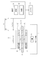
- FIG. 1 is a configuration diagram showing a drive system in one embodiment
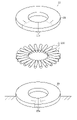
- FIG. 2 is a perspective view showing the configuration of the drive transmission section of the drive device
- FIG. 3 is an explanatory diagram for explaining the control mode of the control device
- FIG. 4 is an explanatory diagram for explaining the control mode of the control device
- FIG. 5 is a perspective view showing the configuration of the drive transmission portion of the drive device in the modified example.
- a drive system 10 of the present embodiment shown in FIG. 1 is used, for example, in a refrigeration cycle device 11 of a vehicle air conditioner.
- the drive system 10 opens and closes the valve device 12 that adjusts the flow rate of the refrigerant in the refrigerant circulation flow path of the refrigeration cycle device 11 .
- the drive system 10 includes a drive device 20 that drives the valve device 12 to open and close, and a control device 30 that controls the drive of the drive device 20 .
- the drive device 20 includes a motor portion 21 as a drive source and a drive transmission portion 22 that transmits the rotational driving force of the motor portion 21 to the valve device 12 on the load side.
- the motor unit 21 of the present embodiment is configured by either a complete electric motor or a stator of the electric motor. That is, when the motor unit 21 is a complete electric motor, it rotates the drive-side rotary member 23 of the drive transmission unit 22 based on the driving of the output shaft of the motor.
- the motor section 21 is a stator of an electric motor
- the driving side rotating member 23 of the drive transmission section 22 is configured as a part of the rotor, and the driving side rotating member 23 is rotated based on the driving of the stator.
- the rotation of the motor portion 21 is controlled by the control device 30 through the drive current Ia.
- the drive transmission section 22 includes a drive-side rotating member 23, a magnetic member 24, and a driven-side rotating member 25.
- Both the driving-side rotating member 23 and the driven-side rotating member 25 are disk-shaped.
- the driving-side rotating member 23 and the driven-side rotating member 25 are coaxially arranged and rotatable.
- the driving-side rotating member 23 and the driven-side rotating member 25 respectively have a plurality of magnetic pole portions 23a and 25a at equal intervals in the circumferential direction.
- Each of the magnetic pole portions 23a and 25a has a configuration in which at least the magnetic poles appear on the opposing surfaces of the drive-side rotating member 23 and the driven-side rotating member 25, respectively.
- the number of poles of the magnetic pole portions 25a of the driven-side rotating member 25 is set larger than the number of poles of the magnetic pole portions 23a of the driving-side rotating member 23 by a predetermined number.
- the driving device 20 of this embodiment is provided for driving the valve device 12 that adjusts the flow rate of the refrigerant.
- the driven-side rotating member 25 arranged on the valve device 12 side is arranged in the wet area A1 into which the refrigerant enters.
- the drive-side rotating member 23 arranged on the motor section 21 side is arranged in the waterproof area A2 where the refrigerant is prohibited from entering. Therefore, the drive transmission portion 22 is provided with a partition member 26 for partitioning the wet area A1 and the waterproof area A2.
- the partition member 26 is interposed between the driving-side rotating member 23 and the driven-side rotating member 25 which are axially opposed to each other.
- the drive-side rotating member 23, the partition member 26, and the driven-side rotating member 25 are not in contact with each other.
- the partition member 26 is made of a non-magnetic metal plate material in this embodiment.
- the partition member 26 is immovably provided.
- a plurality of magnetic members 24 are integrally assembled at equal intervals in the circumferential direction between the facing portions of the magnetic pole portions 23 a and 25 a of the drive-side rotation member 23 and the driven-side rotation member 25 . That is, the magnetic member 24 is also immovably provided.
- the driving-side rotating member 23 and the driven-side rotating member 25 are magnetically coupled via the magnetic member 24 at the magnetic pole portions 23a and 25a. When the drive-side rotating member 23 rotates, the driven-side rotating member 25 rotates continuously via the magnetic member 24 .
- the number of magnetic members 24 is set to the same number as the total number of pole pairs of the magnetic pole portions 23 a and 25 a of the driving side rotating member 23 and the driven side rotating member 25 . That is, the number of poles of the magnetic pole portion 25a of the driven-side rotating member 25 is made larger than that of the magnetic pole portion 23a of the driving-side rotating member 23, and the total number of pole pairs of the magnetic pole portions 23a and 25a and the number of the magnetic members 24 are set to the same number, and the drive transmission section 22 is configured to function as a magnetic reduction section.
- the drive transmission unit 22 reduces speed in the process of transmitting rotation from the driving side rotating member 23 to the driven side rotating member 25 via the magnetic member 24 .
- the control device 30 includes 1) one or more processors that execute various processes according to a computer program (software), and 2) an application specific integrated circuit (ASIC) that executes at least part of the various processes. It may be configured as circuitry including one or more dedicated hardware circuits, or 3) combinations thereof.
- a processor includes a CPU and memory, such as RAM and ROM, which stores program code or instructions configured to cause the CPU to perform processes.
- Memory or computer-readable media includes any available media that can be accessed by a general purpose or special purpose computer.
- the control device 30 controls driving of the motor section 21 through the drive current Ia supplied to the motor section 21 of the drive device 20 .
- the control device 30 includes a current detector 31 and a phase detector 32 .
- the current detection unit 31 detects the load current Im when the motor unit 21 is driven, which is correlated with the magnitude of the load, at predetermined intervals.
- the phase detector 32 uses the load current Im detected by the current detector 31 to detect a phase shift amount d ⁇ that can occur between the drive-side rotating member 23 and the driven-side rotating member 25 . As the load increases, the phase shift amount d ⁇ that can occur between the drive-side rotating member 23 and the driven-side rotating member 25 increases.
- the torque T1 generated by the drive-side rotating member 23 can be expressed by the following equation [Equation 1].
- the torque T2 generated by the driven-side rotating member 25 can be expressed by the following equation [Equation 2].
- [Equation 1] and [Equation 2] are the number of pole pairs n of the magnetic pole portion 23a of the driving-side rotating member 23, the phase shift amount d ⁇ that can occur in the driven-side rotating member 25, and the peak of the torque T2 generated at the driven-side rotating member 25. It can be expressed using torque T0 (see FIG. 4), reduction ratio R, and transmission efficiency ⁇ .
- [Equation 1] and [Equation 2] are expressions created with the driven side rotating member 25 as a base point.
- the torque Tm generated by the motor unit 21 can be expressed as in the following equation [Equation 3].
- [Equation 3] can be expressed using the torque constant kT, the load current Im of the motor section 21, and the no-load current I0.
- phase shift amount d ⁇ that may occur at different times when the motor unit 21 is driven can be calculated based on the load current Im of the motor unit 21 .
- the phase detection unit 32 holds a correlation map between the load current Im and the phase shift amount d ⁇ , which is created in advance using [Equation 4], and from the load current Im obtained when the motor unit 21 is driven, A phase shift amount d ⁇ that can occur at each time is obtained by referring to the correlation map.
- the phase detection unit 32 holds [Equation 4] and obtains the phase shift amount d ⁇ that can occur from time to time from the load current Im obtained when the motor unit 21 is driven.
- the standard rotation angle R ⁇ a of the drive-side rotation member 23 with respect to the target rotation angle ⁇ a of the driven-side rotation member 25 is on the standard straight line L1.
- the rotation angle of the driven-side rotating member 25 with respect to the rotation angle R ⁇ a of the drive-side rotation member 23 is the rotation angle ⁇ a ⁇ d ⁇ on the driving straight line L2.
- the rotational delay of the driven-side rotating member 25 is the phase shift amount d ⁇ obtained based on the load current Im of the motor section 21 . If no measures are taken, the rotation angle of the driven-side rotating member 25 with respect to the rotation angle R ⁇ a of the drive-side rotating member 23 will be the rotation angle ⁇ a ⁇ d ⁇ , deviating from the target rotation angle ⁇ a. It is feared that such a delay in rotation of the driven-side rotating member 25 affects the accuracy of the opening/closing operation of the valve device 12 .
- the control device 30 including the phase detection unit 32 of the present embodiment has a control mode that takes into account the concerns above. That is, the phase detection unit 32 detects the phase shift amount d ⁇ of the driven-side rotating member 25 obtained based on the load current Im of the motor unit 21 with respect to the rotation angle R ⁇ a, which is the standard position of the driving-side rotating member 23. It is added as a correction deviation amount Rd ⁇ . If the target position of the drive-side rotating member 23 is set to the leading-side rotation angle R ⁇ a+Rd ⁇ including the correction, the phase shift amount d ⁇ of the driven-side rotating member 25 is offset and becomes small.
- the phase shift amount d ⁇ is directly used as the correction term on the advance side, but a numerical value adjusted by multiplying the phase shift amount d ⁇ by a coefficient may be used as the correction term.
- the control device 30 of the present embodiment controls the motor portion 21 so that the motor portion 21 is driven at the rotation angle R ⁇ a+Rd ⁇ of the target position of the driving side rotating member 23, which takes into account the phase shift amount d ⁇ of the driven side rotating member 25.
- a driving current Ia to be supplied is set.
- the actual rotation angle of the driven-side rotating member 25 can be the rotation angle ⁇ a+d ⁇ by the correction deviation amount Rd ⁇ . That is, the relative positions of the drive-side rotating member 23 and the driven-side rotating member 25 may shift, resulting in a stopped state.
- the control device 30 of the present embodiment sets the target position of the drive-side rotating member 23 to the standard position when the motor portion 21 is stopped by drive control that takes into account the phase shift amount d ⁇ of the driven-side rotating member 25.
- a return control to return to the rotation angle R ⁇ a is also performed.
- the rotation angle R ⁇ a is completely returned to the standard position, but a numerical value adjusted to approach the standard position may be used.
- the control device 30 performs an abnormality determination using the phase shift amount d ⁇ , and stops driving the motor section 21, for example, when an abnormality is determined. Further, in this case, the control device 30 may output an abnormality signal to, for example, the host system 13 to inform the host system 13 of the abnormality. It is also possible to cause the host system 13 to take appropriate measures.
- the drive device 20 is driven by the motor section 21 based on the drive current Ia supplied from the control device 30 .
- the drive of the motor portion 21 is transmitted through the drive transmission portion 22 in a non-contact manner, and is decelerated during the drive transmission process.
- the valve device 12 receives the driving force output from the drive device 20 to open and close.
- the flow rate of the refrigerant flowing through the refrigerant circulation channel of the refrigeration cycle device 11 is adjusted according to the opening/closing mode of the valve device 12 .
- the control device 30 uses the current detection section 31 to detect the load current Im when the motor section 21 is driven, which is correlated with the magnitude of the load.
- the phase detector 32 obtains the phase shift amount d ⁇ of the driven-side rotating member 25 from the detected load current Im.
- the control device 30 generates the driving current Ia such that the rotation angle of the driven-side rotating member 25 becomes an appropriate angle in consideration of the phase shift amount d ⁇ at each time. That is, the control device 30 can accurately control the rotation angle of the driven-side rotating member 25 through the drive current Ia supplied to the motor section 21 . In this way, even if the magnitude of the load fluctuates, the effect on the opening/closing operation of the valve device 12 is kept small, and the opening/closing operation of the valve device 12 can be performed with sufficiently high accuracy.
- a rotation sensor for detecting rotation information of the driven-side rotating member 25 can be omitted. Since the rotation sensor can be omitted, the installation space for the rotation sensor to be prepared in the vicinity of the driven-side rotating member 25 becomes unnecessary, and the installation of the rotation sensor becomes unnecessary. In the drive system 10 of the present embodiment, it is possible to realize a configuration with a small number of rotation sensors used in the non-contact drive transmission section 22 .
- the controller 30 determines that an abnormality accompanied by a risk of stepping out may occur between the drive-side rotating member 23 and the driven-side rotating member 25 of the drive transmission unit 22. perform anomaly judgment. It is possible to prevent troubles due to out-of-step between the driving-side rotating member 23 and the driven-side rotating member 25 . Moreover, if an abnormality signal is output from the control device 30 to the host system 13 as a peripheral device as an anomaly notification indicating that an anomaly has occurred in the anomaly determination, the host system 13 can be made to take appropriate measures.
- the partition wall member 26 separates the waterproof area A2 where the motor section 21 and the driving-side rotating member 23 are arranged and the wet area A1 where the driven-side rotating member 25 is arranged.
- a transmission unit 22 is used. It is possible to appropriately control the drive device 20 having such a drive transmission section 22 .
- the non-contact drive transmission section 22 using magnetic coupling can easily have the function of decelerating in the drive transmission process from the driving side rotating member 23 to the driven side rotating member 25 . It is possible to appropriately control the drive device 20 having such a drive transmission section 22 .
- the magnetic member 24 is immovable, and the driven side rotating member 25 having the magnetic pole portion 25a is rotatable.
- the magnetic member 27 may be made rotatable as a part of the driven-side rotating member 28, and the disc magnetic pole member 29 having a plurality of magnetic pole portions 29a at regular intervals in the circumferential direction may be configured as immovable.
- the driving-side rotating member 23, the driven-side rotating member 28 having the magnetic member 27, and the disk magnetic pole member 29 are magnetically coupled in the axial direction, the magnetic member 27 is displaced as the driving-side rotating member 23 rotates.
- the driven side rotating member 28 rotates continuously.
- the magnetic member 27 may have a rollable outer shape and may be rollably supported. By doing so, the magnetic member 27 can also function as a bearing for the driven side rotating member 28 .
- the numbers of the magnetic pole portions 23a of the drive-side rotating member 23, the magnetic members 24, and the magnetic pole portions 25a of the driven-side rotating member 25 may be changed as appropriate.
- the number of the magnetic members 27 of the driven side rotating member 28 and the number of the magnetic pole portions 29a of the disc magnetic pole member 29 may be changed as appropriate. In this case, it is possible to set not only the number of magnetically decelerating drive transmission units 22, but also the number of speed-increasing or constant-speed transmissions.
- the drive transmission portion 22 shown in FIG. 2 has a configuration in which the magnetic pole portion 23a of the drive-side rotating member 23, the magnetic member 24, and the magnetic pole portion 25a of the driven-side rotating member 25 face each other in the axial direction. 5, the magnetic pole portion 23a of the driving side rotating member 23, the driven side rotating member 28 having the magnetic member 27, and the magnetic pole portion 29a of the disc magnetic pole member 29 are configured to face each other in the axial direction. board. It is good also as a structure which makes this diametrically opposed. Moreover, it is good also as a facing structure which mixed the axial direction and the radial direction.
- the drive system 10 drives and controls the valve device 12 that adjusts the flow rate of the refrigerant in the refrigerant circulation flow path of the refrigeration cycle device 11, but may be applied to devices other than this. Depending on the device to be applied, the partition member 26 may be omitted as appropriate.
- references herein to "at least one of A and B" should be understood to mean “A only, or B only, or both A and B.”
Landscapes
- Engineering & Computer Science (AREA)
- General Engineering & Computer Science (AREA)
- Mechanical Engineering (AREA)
- Power Engineering (AREA)
- Connection Of Motors, Electrical Generators, Mechanical Devices, And The Like (AREA)
Abstract
制御装置(30)は、電流検出部(31)にて検出したモータ部(21)の負荷電流(Im)に基づき、互いに磁気連結する駆動伝達部(22)の駆動側回転部材(23)に対する従動側回転部材(25)の位相ずれ量を位相検出部(32)にて検出する。制御装置(30)は、駆動側回転部材(23)の目標位置を位相ずれ量に基づいた進み側の補正を含んで設定し、これに基づいたモータ部(21)の駆動制御を行う。
Description
本出願は、2021年5月12日に出願された日本出願番号2021-081132号に基づくもので、ここにその記載内容を援用する。
本開示は、非接触式の駆動伝達部を用いる駆動装置の制御装置、及びその駆動装置と制御装置とを備える駆動システムに関する。
電動モータを駆動源とする駆動装置において、電動モータの回転駆動力を非接触式の駆動伝達部を用いて負荷側に伝達する構成のものがある。非接触式の駆動伝達部は、例えば駆動側回転部材と従動側回転部材とが連回り可能に互いに磁気連結されてなる。このような駆動伝達部を用いる場合、駆動側回転部材の回転に従動側回転部材が適切に追従できているかを制御装置にて検出し、電動モータの制御に反映することが行われている。例えば特許文献1にて開示の技術等では、駆動側回転部材及び従動側回転部材に対して各回転部材の回転情報を検出する回転センサがそれぞれに設置されている。
駆動側回転部材や従動側回転部材を検出対象とする回転センサは、各回転部材の近傍に設置する必要がある。そのため、回転センサの配置スペースが必要であったり組み付けが必要であったりと、まだこれらの点で改善の余地がある。本発明者は、回転部材を検出対象とする回転センサの数を極力減らしたいと考えている。本開示の目的は、非接触式の駆動伝達部に用いる回転センサを少ない構成にて実現できる駆動装置の制御装置及び駆動システムを提供することにある。
本開示の一態様に係る駆動装置の制御装置において、前記駆動装置(20)は、モータ部(21)と、互いに磁気連結する駆動側回転部材(23)及び従動側回転部材(25,29)を有する駆動伝達部(22)とを含む。前記駆動装置(20)は、前記モータ部の駆動に基づく前記駆動側回転部材の回転に伴い前記従動側回転部材が連回りして負荷(12)に駆動力を伝達するように構成されている。前記制御装置(30)は、前記駆動装置(20)における前記モータ部の駆動を制御するように構成されている。前記制御装置(30)は、前記モータ部の負荷電流(Im)を検出する電流検出部(31)と、前記電流検出部にて検出した前記負荷電流に基づき、前記駆動側回転部材に対する前記従動側回転部材の位相ずれ量(dθ)を検出する位相検出部(32)と、を備える。前記制御装置(30)は、前記駆動側回転部材の目標位置を標準位置(Rθa)から前記位相ずれ量に基づいた進み側に設定して前記モータ部の駆動制御を行う。
本開示の更なる態様に係る駆動システムは、モータ部(21)と、互いに磁気連結する駆動側回転部材(23)及び従動側回転部材(25,29)を有する駆動伝達部(22)とを含み、前記モータ部の駆動に基づく前記駆動側回転部材の回転に伴い前記従動側回転部材が連回りして負荷(12)に駆動力を伝達するように構成される駆動装置(20)と、前記駆動装置における前記モータ部の駆動を制御する制御装置(30)とを備える駆動システム(10)であって、前記制御装置は、前記モータ部の負荷電流(Im)を検出する電流検出部(31)と、前記電流検出部にて検出した前記負荷電流に基づき、前記駆動側回転部材に対する前記従動側回転部材の位相ずれ量(dθ)を検出する位相検出部(32)と、を備え、前記制御装置(30)は、前記駆動側回転部材の目標位置を標準位置(Rθa)から前記位相ずれ量に基づいた進み側に設定して前記駆動装置の前記モータ部の駆動制御を行う。
上記駆動装置の制御装置及び駆動システムによれば、電流検出部にて検出したモータ部の負荷電流に基づき、互いに磁気連結する駆動伝達部の駆動側回転部材に対する従動側回転部材の位相ずれ量が位相検出部にて検出される。制御装置は、駆動側回転部材の目標位置を標準位置から位相ずれ量に基づいた進み側の設定としてモータ部の駆動を制御する。これを受け、従動側回転部材の実位置は、狙いの位置若しくは狙いの位置に極めて近似するものとなる。つまり、従動側回転部材の回転情報を検出する回転センサを用いなくても適切な制御が可能であり、非接触式の駆動伝達部を用いる駆動装置及び駆動システムにおいて回転センサを少なくして構成することが可能である。
本開示についての上記目的およびその他の目的、特徴や利点は、添付の図面を参照しながら下記の詳細な記述により、より明確になる。その図面は、
図1は、一実施形態における駆動システムを示す構成図であり、
図2は、駆動装置の駆動伝達部の構成を示す斜視図であり、
図3は、制御装置の制御態様を説明するための説明図であり、
図4は、制御装置の制御態様を説明するための説明図であり、
図5は、変更例における駆動装置の駆動伝達部の構成を示す斜視図である。
以下、本開示の一実施形態について説明する。
[駆動システムの構成]
図1に示す本実施形態の駆動システム10は、例えば車両用空調装置の冷凍サイクル装置11に用いられる。駆動システム10は、冷凍サイクル装置11の冷媒循環流路において冷媒の流量を調整する弁装置12の開閉を行う。駆動システム10は、弁装置12を開閉駆動する駆動装置20と、駆動装置20の駆動を制御する制御装置30とを備えている。
[駆動システムの構成]
図1に示す本実施形態の駆動システム10は、例えば車両用空調装置の冷凍サイクル装置11に用いられる。駆動システム10は、冷凍サイクル装置11の冷媒循環流路において冷媒の流量を調整する弁装置12の開閉を行う。駆動システム10は、弁装置12を開閉駆動する駆動装置20と、駆動装置20の駆動を制御する制御装置30とを備えている。
[駆動装置の構成]
駆動装置20は、駆動源としてのモータ部21と、モータ部21の回転駆動力を負荷側の弁装置12に伝達する駆動伝達部22とを備えている。本実施形態のモータ部21は、電動モータの完成体、又は電動モータのステータのいずれかで構成されている。すなわち、モータ部21は、電動モータの完成体である場合、モータの出力軸の駆動に基づいて駆動伝達部22の駆動側回転部材23を回転させる。又は、モータ部21は、電動モータのステータである場合、駆動伝達部22の駆動側回転部材23がロータの一部として構成され、ステータの駆動に基づいて駆動側回転部材23を回転させる。モータ部21は、制御装置30により駆動電流Iaを通じて回転が制御される。
駆動装置20は、駆動源としてのモータ部21と、モータ部21の回転駆動力を負荷側の弁装置12に伝達する駆動伝達部22とを備えている。本実施形態のモータ部21は、電動モータの完成体、又は電動モータのステータのいずれかで構成されている。すなわち、モータ部21は、電動モータの完成体である場合、モータの出力軸の駆動に基づいて駆動伝達部22の駆動側回転部材23を回転させる。又は、モータ部21は、電動モータのステータである場合、駆動伝達部22の駆動側回転部材23がロータの一部として構成され、ステータの駆動に基づいて駆動側回転部材23を回転させる。モータ部21は、制御装置30により駆動電流Iaを通じて回転が制御される。
図1及び図2に示すように、駆動伝達部22は、駆動側回転部材23と、磁性部材24と、従動側回転部材25とを備えている。駆動側回転部材23及び従動側回転部材25は、ともに円盤状をなしている。駆動側回転部材23及び従動側回転部材25は、同軸上に配置されて、それぞれ回転可能に設けられている。駆動側回転部材23及び従動側回転部材25には、周方向等間隔に複数の磁極部23a,25aをそれぞれ有している。各磁極部23a,25aは、駆動側回転部材23及び従動側回転部材25それぞれの対向面に少なくとも磁極が現れる構成である。本実施形態では、駆動側回転部材23の磁極部23aの極数よりも従動側回転部材25の磁極部25aの極数の方が所定数多く設定されている。
ここで、本実施形態の駆動装置20は、冷媒の流量を調整する弁装置12の駆動のために設けられている。弁装置12側に配置される従動側回転部材25は、冷媒が進入する被水領域A1に配置される。これに対し、モータ部21側に配置される駆動側回転部材23は、冷媒の進入が禁止された防水領域A2に配置される。そのため、駆動伝達部22においては、被水領域A1と防水領域A2とを仕切るための隔壁部材26を備えている。隔壁部材26は、互いに軸方向に対向する位置関係の駆動側回転部材23と従動側回転部材25との間に介装されている。駆動側回転部材23、隔壁部材26、及び従動側回転部材25は、互いに非接触である。
隔壁部材26は、本実施形態では非磁性金属板材にて作製されている。隔壁部材26は、不動に設けられている。隔壁部材26において、駆動側回転部材23及び従動側回転部材25の各磁極部23a,25aの対向部間には、周方向等間隔に複数の磁性部材24が一体に組み込まれている。つまり、磁性部材24も不動に設けられている。駆動側回転部材23と従動側回転部材25とは、磁性部材24を介して互いの磁極部23a,25aが磁気連結している。駆動側回転部材23が回転すると、磁性部材24を介して従動側回転部材25が連回りする。
磁性部材24の数は、本実施形態では、駆動側回転部材23及び従動側回転部材25の各磁極部23a,25aの極対数を合計した数と同数に設定されている。つまり、駆動側回転部材23の磁極部23aよりも従動側回転部材25の磁極部25aの方の極数を多くし、各磁極部23a,25aの極対数の合計数と磁性部材24の数とを同数に設定し、駆動伝達部22が磁気減速部として機能するように構成されている。駆動伝達部22は、駆動側回転部材23から磁性部材24を介して従動側回転部材25に回転を伝達する過程で減速するものとなっている。
[制御装置の構成]
制御装置30は、1)コンピュータプログラム(ソフトウェア)に従って各種処理を実行する1つ以上のプロセッサ、2)各種処理のうち少なくとも一部の処理を実行する、特定用途向け集積回路(ASIC)等の1つ以上の専用のハードウェア回路、或いは3)それらの組み合わせ、を含む回路(circuitry)として構成し得る。プロセッサは、CPU並びに、RAM及びROM等のメモリを含み、メモリは、処理をCPUに実行させるように構成されたプログラムコードまたは指令を格納している。メモリすなわちコンピュータ可読媒体は、汎用または専用のコンピュータでアクセスできるあらゆる利用可能な媒体を含む。
制御装置30は、1)コンピュータプログラム(ソフトウェア)に従って各種処理を実行する1つ以上のプロセッサ、2)各種処理のうち少なくとも一部の処理を実行する、特定用途向け集積回路(ASIC)等の1つ以上の専用のハードウェア回路、或いは3)それらの組み合わせ、を含む回路(circuitry)として構成し得る。プロセッサは、CPU並びに、RAM及びROM等のメモリを含み、メモリは、処理をCPUに実行させるように構成されたプログラムコードまたは指令を格納している。メモリすなわちコンピュータ可読媒体は、汎用または専用のコンピュータでアクセスできるあらゆる利用可能な媒体を含む。
制御装置30は、駆動装置20のモータ部21に供給する駆動電流Iaを通じてモータ部21の駆動を制御する。制御装置30は、電流検出部31と、位相検出部32とを備えている。電流検出部31は、負荷の大きさに相関のあるモータ部21の駆動時の負荷電流Imを所定周期毎に検出する。位相検出部32は、電流検出部31にて検出した負荷電流Imを用い、駆動側回転部材23と従動側回転部材25との間に生じ得る位相ずれ量dθを検出する。負荷が増大すると、駆動側回転部材23と従動側回転部材25との間に生じ得る位相ずれ量dθは増大する関係である。
ここで、駆動側回転部材23にて発生するトルクT1は、次式[数1]のように表すことが可能である。また、従動側回転部材25にて発生するトルクT2は、次式[数2]のように表すことが可能である。[数1][数2]は、駆動側回転部材23の磁極部23aの極対数n、従動側回転部材25に生じ得る位相ずれ量dθ、従動側回転部材25にて発生するトルクT2のピークトルクT0(図4参照)、減速比R、伝達効率ηを用いて表すことができる。なお、[数1][数2]は、従動側回転部材25を基点として作成した式である。


また、モータ部21で発生するトルクTmは、次式[数3]のように表すことが可能である。[数3]は、トルク定数kT、モータ部21の負荷電流Im、無負荷電流I0を用いて表すことができる。

上記式より、定常状態では、モータ部21で発生するトルクTmと駆動側回転部材23にて発生するトルクT1とが同等、すなわちTm=T1である。そのため、従動側回転部材25に生じ得る位相ずれ量dθは、次式[数4]で表すことができる。

上記[数4]では、kT、I0、η、R、T0、nがそれぞれ設計値として事前に得ることができる。そのため、モータ部21の駆動時のその時々に生じ得る位相ずれ量dθは、モータ部21の負荷電流Imに基づいて算出することが可能である。これを踏まえ、位相検出部32は、[数4]を用いて予め作成した負荷電流Imと位相ずれ量dθとの相関マップを保持しており、モータ部21の駆動時に取得する負荷電流Imからその時々に生じ得る位相ずれ量dθを相関マップの参照にて得る。なお、位相検出部32は、[数4]を保持しておき、モータ部21の駆動時に取得する負荷電流Imからその時々に生じ得る位相ずれ量dθを都度の算出にて得るようにすることもできる。
図3に示すように、従動側回転部材25の狙いの回転角度θaに対する標準的な駆動側回転部材23の回転角度Rθaは標準直線L1上となる。しかしながら、モータ部21が駆動する負荷が増大、この場合事象として一般的に多い正の負荷が増大すると、駆動側回転部材23の回転角度Rθaに対して従動側回転部材25の回転に遅れが生じる。つまり、駆動側回転部材23の回転角度Rθaに対して従動側回転部材25の回転角度は、駆動時直線L2上の回転角度θa-dθとなる。上記では、従動側回転部材25の回転遅れは、モータ部21の負荷電流Imに基づいて得られる位相ずれ量dθである。何も対策しなければ、駆動側回転部材23の回転角度Rθaに対する従動側回転部材25の回転角度は回転角度θa-dθとなり、狙いの回転角度θaからずれてしまう。このような従動側回転部材25の回転遅れは、弁装置12の開閉動作の精度に影響することが懸念される。
本実施形態の位相検出部32を含む制御装置30は、上記懸念を考慮した制御態様となっている。すなわち、位相検出部32は、駆動側回転部材23の標準位置である回転角度Rθaに対し、モータ部21の負荷電流Imに基づいて得られる従動側回転部材25の位相ずれ量dθの相当分を補正ずれ量Rdθとして加算する。駆動側回転部材23の目標位置を補正を含む進み側の回転角度Rθa+Rdθと設定すれば、従動側回転部材25の位相ずれ量dθは相殺されて小さくなる。従動側回転部材25の実回転角度を標準直線L1上の狙いの回転角度θa、若しくは標準直線L1に極めて近似させることが可能である。なお本実施形態では、位相ずれ量dθをそのまま進み側の補正項に用いたが、位相ずれ量dθに係数を掛けて調整した数値を補正項に用いてもよい。こうして本実施形態の制御装置30は、モータ部21の駆動制御として、従動側回転部材25の位相ずれ量dθを加味した駆動側回転部材23の目標位置の回転角度Rθa+Rdθにて、モータ部21に供給する駆動電流Iaを設定している。
また、モータ部21の停止時においては、負荷側の弁装置12が無負荷状態に戻ると、補正ずれ量Rdθ分、従動側回転部材25の実回転角度が回転角度θa+dθとなり得る。つまり、駆動側回転部材23と従動側回転部材25との相対位置がずれて停止状態となり得る。本実施形態の制御装置30は、これを考慮し、従動側回転部材25の位相ずれ量dθを加味した駆動制御によりモータ部21が停止した際、駆動側回転部材23の目標位置を標準位置の回転角度Rθaに戻す戻し制御を行うようにもなっている。なお本実施形態では、完全に標準位置の回転角度Rθaに戻したが、標準位置側に近づけるべく調整した数値を用いてもよい。
また図4に示すように、位相検出部32から得られる位相ずれ量dθが許容閾値Th1,Th2を超える場合、負荷側が想定最大負荷を超えるような異常状態であることを意味する。駆動側回転部材23と従動側回転部材25との脱調リスクが高まる。そのため、制御装置30は、位相ずれ量dθを用いる異常判定を行い、異常と判定した際には例えばモータ部21の駆動を停止する。またこの場合、制御装置30は、例えば上位システム13等に異常信号を出力し、上位システム13等に異常報知するようにしてもよい。上位システム13にて適切な対処を行わせることも可能である。
[本実施形態の動作(作用)]
本実施形態の駆動システム10において、駆動装置20は、制御装置30からの駆動電流Iaの供給に基づいてモータ部21が駆動する。モータ部21の駆動は、駆動伝達部22にて非接触で回転駆動が伝達されるとともに、その駆動伝達過程で減速される。そして、弁装置12は、駆動装置20から出力される駆動力を受けて開閉動作する。弁装置12の開閉態様に応じて、冷凍サイクル装置11の冷媒循環流路を流れる冷媒の流量調整が行われる。
本実施形態の駆動システム10において、駆動装置20は、制御装置30からの駆動電流Iaの供給に基づいてモータ部21が駆動する。モータ部21の駆動は、駆動伝達部22にて非接触で回転駆動が伝達されるとともに、その駆動伝達過程で減速される。そして、弁装置12は、駆動装置20から出力される駆動力を受けて開閉動作する。弁装置12の開閉態様に応じて、冷凍サイクル装置11の冷媒循環流路を流れる冷媒の流量調整が行われる。
制御装置30は、負荷の大きさに相関のあるモータ部21の駆動時の負荷電流Imを電流検出部31にて検出する。位相検出部32は、検出した負荷電流Imから従動側回転部材25の位相ずれ量dθを得る。制御装置30は、従動側回転部材25の回転角度がその時々の位相ずれ量dθを加味した適正角度となるような駆動電流Iaを生成する。つまり、制御装置30は、モータ部21に供給する駆動電流Iaを通じて、従動側回転部材25の回転角度の制御を精度良く行うことが可能である。こうして、負荷の大きさが変動しても弁装置12の開閉動作への影響は小さく抑えられており、弁装置12の開閉動作を十分に高い精度で行うことができるようになっている。
しかも、従動側回転部材25の回転情報を検出する回転センサが省略可能である。回転センサを省略できる分、従動側回転部材25の近傍に用意すべき回転センサの配置スペースが不要となり、その回転センサの組み付けも不要となる。本実施形態の駆動システム10では、非接触式の駆動伝達部22に用いる回転センサを少ない構成にて実現することが可能である。
[本実施形態の効果]
本実施形態の効果について説明する。
(1)本実施形態の制御装置30は、電流検出部31にて検出したモータ部21の負荷電流Imに基づき、互いに磁気連結する駆動伝達部22の駆動側回転部材23に対する従動側回転部材25の位相ずれ量dθを位相検出部32にて検出する。制御装置30は、駆動側回転部材23の目標位置を位相ずれ量dθに基づく補正を含む進み側の回転角度Rθa+Rdθと設定し、これに基づいたモータ部21の駆動制御を行う。これを受け、従動側回転部材25の実位置は、狙いの位置若しくは狙いの位置に極めて近似するものとなる。つまり、従動側回転部材25の回転情報を検出する回転センサを用いなくても適切な制御が可能であり、本実施形態のように非接触式の駆動伝達部22を用いる駆動装置20及び駆動システム10において回転センサを少なくして構成することができる。
本実施形態の効果について説明する。
(1)本実施形態の制御装置30は、電流検出部31にて検出したモータ部21の負荷電流Imに基づき、互いに磁気連結する駆動伝達部22の駆動側回転部材23に対する従動側回転部材25の位相ずれ量dθを位相検出部32にて検出する。制御装置30は、駆動側回転部材23の目標位置を位相ずれ量dθに基づく補正を含む進み側の回転角度Rθa+Rdθと設定し、これに基づいたモータ部21の駆動制御を行う。これを受け、従動側回転部材25の実位置は、狙いの位置若しくは狙いの位置に極めて近似するものとなる。つまり、従動側回転部材25の回転情報を検出する回転センサを用いなくても適切な制御が可能であり、本実施形態のように非接触式の駆動伝達部22を用いる駆動装置20及び駆動システム10において回転センサを少なくして構成することができる。
(2)位相ずれ量dθを加味するモータ部21の駆動制御によりモータ部21が停止した際、制御装置30は、駆動側回転部材23を標準位置の回転角度Rθaに戻す戻し制御を行う。そのため、駆動側回転部材23と従動側回転部材25とを互いに適切な位置関係としておくことができる。
(3)位相ずれ量dθが許容閾値Th1,Th2を超える場合、制御装置30は、駆動伝達部22の駆動側回転部材23と従動側回転部材25との脱調リスクを伴う異常が生じ得るとする異常判定を行う。駆動側回転部材23と従動側回転部材25との脱調による不具合を未然に防止することができる。また、異常判定にて異常が生じた旨の異常報知として、制御装置30から周囲装置としての上位システム13に異常信号を出力すれば、上位システム13にて適切な対処を行わせることもできる。
(4)モータ部21及び駆動側回転部材23の配置される防水領域A2と従動側回転部材25の配置される被水領域A1とを隔壁部材26にて仕切る構造が故に、非接触式の駆動伝達部22が用いられる。このような駆動伝達部22を有する駆動装置20の制御を適切に行うことができる。
(5)磁気連結を用いる非接触式の駆動伝達部22は、駆動側回転部材23から従動側回転部材25への駆動伝達過程で減速する機能を持たせることが容易である。このような駆動伝達部22を有する駆動装置20の制御を適切に行うことができる。
[変更例]
本実施形態は、以下のように変更して実施することができる。本実施形態及び以下の変更例は、技術的に矛盾しない範囲で互いに組み合わせて実施することができる。
本実施形態は、以下のように変更して実施することができる。本実施形態及び以下の変更例は、技術的に矛盾しない範囲で互いに組み合わせて実施することができる。
・上記数式[数1][数4]に対し、更にモータ部21の構成等により得られるコギングトルク関数F(θ)を加味した次式[数5][数6]を用いてもよい。


上記[数5][数6]を用いれば、モータ部21のコギングトルクの影響を十分に排除でき、従動側回転部材25の回転角度の制御をより精度良く行うことができる。ひいては、弁装置12の開閉動作をより精度良く行うことができる。
・上記数式[数4]に対し、更に周囲温度を検出する温度センサが備えられるものでは、温度センサにて検出した周囲温度等の影響を温度係数kαとして加味した次式[数7]を用いてもよい。

上記[数7]を用いれば、周囲温度等の影響を十分に排除でき、従動側回転部材25の回転角度の制御をより精度良く行うことができる。ひいては、弁装置12の開閉動作をより精度良く行うことができる。
・上記図2に示す駆動伝達部22は、磁性部材24を不動、磁極部25aを有する従動側回転部材25を回転可能としていた。これを図5に示すように、磁性部材27を従動側回転部材28の一部として回転可能とし、周方向等間隔に複数の磁極部29aを有する円盤磁極部材29を不動として構成してもよい。このように駆動側回転部材23、磁性部材27を有する従動側回転部材28、及び円盤磁極部材29を軸方向に磁気連結する構成としても、駆動側回転部材23の回転に伴って磁性部材27が周回して従動側回転部材28が連回りする。
また図5に示す駆動伝達部22では、磁性部材27を転動可能な外形形状とし、転動可能に支持する構成としてもよい。このようにすれば、磁性部材27を従動側回転部材28の軸受として機能させることもできる。
・上記図2に示す駆動伝達部22において、駆動側回転部材23の磁極部23a、磁性部材24、従動側回転部材25の磁極部25aの数を適宜変更してもよい。また、図5に示す駆動伝達部22においても、従動側回転部材28の磁性部材27、円盤磁極部材29の磁極部29aの数を適宜変更してもよい。この場合、駆動伝達部22に磁気減速を行わせるそれぞれの数の設定のみならず、増速又は等速伝達を行わせる数の設定を行ってもよい。
・上記図2に示す駆動伝達部22は、駆動側回転部材23の磁極部23a、磁性部材24、従動側回転部材25の磁極部25aを軸方向に対向させる構成としていた。また、図5に示す駆動伝達部22においても、駆動側回転部材23の磁極部23a、磁性部材27を有する従動側回転部材28、円盤磁極部材29の磁極部29aを軸方向に対向させる構成としていた。これを、径方向に対向させる構成としてもよい。また、軸方向と径方向とを混在させた対向構成としてもよい。
・駆動システム10は、冷凍サイクル装置11の冷媒循環流路の冷媒の流量を調整する弁装置12を駆動制御するものであったが、これ以外の装置に適用してもよい。適用する装置によっては、隔壁部材26を適宜省略してもよい。
本明細書における記述「A及びBの少なくとも1つ」は、「Aのみ、または、Bのみ、または、AとBの両方」を意味するものとして理解されたい。
本開示は、実施例に準拠して記述されたが、本開示は当該実施例や構造に限定されるものではないと理解される。本開示は、様々な変形例や均等範囲内の変形をも包含する。加えて、様々な組み合わせや形態、さらには、それらに一要素のみ、それ以上、あるいはそれ以下、を含む他の組み合わせや形態をも、本開示の範疇や思想範囲に入るものである。
本開示は、実施例に準拠して記述されたが、本開示は当該実施例や構造に限定されるものではないと理解される。本開示は、様々な変形例や均等範囲内の変形をも包含する。加えて、様々な組み合わせや形態、さらには、それらに一要素のみ、それ以上、あるいはそれ以下、を含む他の組み合わせや形態をも、本開示の範疇や思想範囲に入るものである。
Claims (9)
- 駆動装置(20)の制御装置(30)であって、
前記駆動装置(20)は、モータ部(21)と、互いに磁気連結する駆動側回転部材(23)及び従動側回転部材(25,29)を有する駆動伝達部(22)とを含み、
前記駆動装置(20)は、前記モータ部の駆動に基づく前記駆動側回転部材の回転に伴い前記従動側回転部材が連回りして負荷(12)に駆動力を伝達するように構成されており、
前記制御装置(30)は、前記駆動装置(20)における前記モータ部の駆動を制御するように構成されており、
前記制御装置(30)は、
前記モータ部の負荷電流(Im)を検出する電流検出部(31)と、
前記電流検出部にて検出した前記負荷電流に基づき、前記駆動側回転部材に対する前記従動側回転部材の位相ずれ量(dθ)を検出する位相検出部(32)と、
を備え、
前記制御装置(30)は、前記駆動側回転部材の目標位置を標準位置(Rθa)から前記位相ずれ量に基づいた進み側に設定して前記モータ部の駆動制御を行う、駆動装置の制御装置。 - 前記位相ずれ量を加味する前記モータ部の駆動制御により前記モータ部が停止した際、前記駆動側回転部材を前記標準位置側に戻す戻し制御を行う、請求項1に記載の駆動装置の制御装置。
- 前記位相ずれ量が許容閾値(Th1,Th2)を超える場合、前記駆動伝達部の前記駆動側回転部材と前記従動側回転部材との脱調リスクを伴う異常が生じ得るとする異常判定を行う、請求項1又は請求項2に記載の駆動装置の制御装置。
- 前記異常判定にて異常が生じた旨の異常報知として周囲装置(13)に異常信号を出力する、請求項3に記載の駆動装置の制御装置。
- 前記位相検出部は、更に前記モータ部のコギングトルクを加味して前記位相ずれ量を検出する、請求項1から請求項4のいずれか1項に記載の駆動装置の制御装置。
- 前記位相検出部は、更に周囲温度を加味して前記位相ずれ量を検出する、請求項1から請求項5のいずれか1項に記載の駆動装置の制御装置。
- 前記駆動装置(20)が制御対象であり、
前記駆動装置(20)は、前記モータ部及び前記駆動側回転部材の配置される領域(A2)と、前記従動側回転部材の配置される領域(A1)とを仕切る隔壁部材(26)を有する、請求項1から請求項6のいずれか1項に記載の駆動装置の制御装置。 - 前記駆動装置(20)が制御対象であり、
前記駆動装置(20)は、前記駆動側回転部材から前記従動側回転部材への駆動伝達過程で減速される磁気減速部として構成された前記駆動伝達部を有する、請求項1から請求項7のいずれか1項に記載の駆動装置の制御装置。 - モータ部(21)と、互いに磁気連結する駆動側回転部材(23)及び従動側回転部材(25,29)を有する駆動伝達部(22)とを含み、前記モータ部の駆動に基づく前記駆動側回転部材の回転に伴い前記従動側回転部材が連回りして負荷(12)に駆動力を伝達するように構成される駆動装置(20)と、
前記駆動装置における前記モータ部の駆動を制御する制御装置(30)と
を備える駆動システム(10)であって、
前記制御装置は、
前記モータ部の負荷電流(Im)を検出する電流検出部(31)と、
前記電流検出部にて検出した前記負荷電流に基づき、前記駆動側回転部材に対する前記従動側回転部材の位相ずれ量(dθ)を検出する位相検出部(32)と、
を備え、
前記制御装置(30)は、前記駆動側回転部材の目標位置を標準位置(Rθa)から前記位相ずれ量に基づいた進み側に設定して前記駆動装置の前記モータ部の駆動制御を行う、駆動システム。
Applications Claiming Priority (2)
| Application Number | Priority Date | Filing Date | Title |
|---|---|---|---|
| JP2021081132A JP7552496B2 (ja) | 2021-05-12 | 2021-05-12 | 駆動装置の制御装置及び駆動システム |
| JP2021-081132 | 2021-05-12 |
Publications (1)
| Publication Number | Publication Date |
|---|---|
| WO2022239804A1 true WO2022239804A1 (ja) | 2022-11-17 |
Family
ID=84029204
Family Applications (1)
| Application Number | Title | Priority Date | Filing Date |
|---|---|---|---|
| PCT/JP2022/019954 Ceased WO2022239804A1 (ja) | 2021-05-12 | 2022-05-11 | 駆動装置の制御装置及び駆動システム |
Country Status (2)
| Country | Link |
|---|---|
| JP (1) | JP7552496B2 (ja) |
| WO (1) | WO2022239804A1 (ja) |
Citations (4)
| Publication number | Priority date | Publication date | Assignee | Title |
|---|---|---|---|---|
| JP2005224041A (ja) * | 2004-02-06 | 2005-08-18 | Mitsubishi Heavy Ind Ltd | 脱調防止装置及び燃料供給装置 |
| JP2006078095A (ja) * | 2004-09-10 | 2006-03-23 | Hitachi Home & Life Solutions Inc | 冷蔵庫 |
| JP2013044361A (ja) * | 2011-08-23 | 2013-03-04 | Kobe Steel Ltd | 変速磁気カップリング装置 |
| JP2013518226A (ja) * | 2010-01-28 | 2013-05-20 | チンフアダーシェイ | 高温ガス冷却原子炉ヘリウムガススペースの密封伝動装置及びその駆動装置 |
-
2021
- 2021-05-12 JP JP2021081132A patent/JP7552496B2/ja active Active
-
2022
- 2022-05-11 WO PCT/JP2022/019954 patent/WO2022239804A1/ja not_active Ceased
Patent Citations (4)
| Publication number | Priority date | Publication date | Assignee | Title |
|---|---|---|---|---|
| JP2005224041A (ja) * | 2004-02-06 | 2005-08-18 | Mitsubishi Heavy Ind Ltd | 脱調防止装置及び燃料供給装置 |
| JP2006078095A (ja) * | 2004-09-10 | 2006-03-23 | Hitachi Home & Life Solutions Inc | 冷蔵庫 |
| JP2013518226A (ja) * | 2010-01-28 | 2013-05-20 | チンフアダーシェイ | 高温ガス冷却原子炉ヘリウムガススペースの密封伝動装置及びその駆動装置 |
| JP2013044361A (ja) * | 2011-08-23 | 2013-03-04 | Kobe Steel Ltd | 変速磁気カップリング装置 |
Also Published As
| Publication number | Publication date |
|---|---|
| JP7552496B2 (ja) | 2024-09-18 |
| JP2022175025A (ja) | 2022-11-25 |
Similar Documents
| Publication | Publication Date | Title |
|---|---|---|
| US9509242B2 (en) | Systems and method for speed and torque control of a DC motor | |
| US8212511B2 (en) | Method and apparatus for limiting torque in an electric drive motor | |
| JP2003239741A5 (ja) | ||
| JP2003269171A (ja) | 水温制御バルブの故障検出装置 | |
| JP2009543007A (ja) | 注入および排出制御を行う粘性ファン駆動装置システム | |
| US10767890B2 (en) | Load operation control system | |
| WO2020054525A1 (ja) | 送風装置 | |
| EP2955384B1 (en) | Sensorless low flow electric water pump and method of regulating flow therewith | |
| JP5775336B2 (ja) | モータ制御装置 | |
| WO2022239804A1 (ja) | 駆動装置の制御装置及び駆動システム | |
| CN106016577B (zh) | 涡轮式流量控制装置 | |
| US20140209180A1 (en) | Viscous fan drive systems having fill and scavenge control | |
| KR19990078373A (ko) | 직류 무브러시 모터의 제어방법 | |
| JP4045894B2 (ja) | エンジンおよび燃料電池の冷却装置 | |
| US10505481B2 (en) | Method and device for operating an electronically commutated servo motor and position control unit having a servo motor | |
| EP1315280B1 (en) | Sensor system for controlling a motor | |
| CN112740536A (zh) | 具有电动机的致动器和控制电动机以维持当前位置的方法 | |
| WO2016163002A1 (ja) | アクチュエータの制御装置、アクチュエータ、バルブ駆動装置およびアクチュエータの制御方法 | |
| JP4669858B2 (ja) | 冷却装置 | |
| US10284128B2 (en) | Controller for increasing torque output of electric motors | |
| JP4260599B2 (ja) | 電磁クラッチ付回転機のロック検出機構 | |
| US11128243B2 (en) | Drive apparatus of electric motor and electric pump apparatus | |
| US20210332739A1 (en) | Controller of fan coupling device | |
| JP2001333589A (ja) | モータの過負荷状態検出装置 | |
| JP2007151376A (ja) | モータアクチュエータにおける出力軸の原点位置検出方法、及び、その原点位置検出の異常判定方法 |
Legal Events
| Date | Code | Title | Description |
|---|---|---|---|
| 121 | Ep: the epo has been informed by wipo that ep was designated in this application |
Ref document number: 22807503 Country of ref document: EP Kind code of ref document: A1 |
|
| NENP | Non-entry into the national phase |
Ref country code: DE |
|
| 122 | Ep: pct application non-entry in european phase |
Ref document number: 22807503 Country of ref document: EP Kind code of ref document: A1 |