WO2022239145A1 - 定点観測装置、定点観測システム - Google Patents
定点観測装置、定点観測システム Download PDFInfo
- Publication number
- WO2022239145A1 WO2022239145A1 PCT/JP2021/018039 JP2021018039W WO2022239145A1 WO 2022239145 A1 WO2022239145 A1 WO 2022239145A1 JP 2021018039 W JP2021018039 W JP 2021018039W WO 2022239145 A1 WO2022239145 A1 WO 2022239145A1
- Authority
- WO
- WIPO (PCT)
- Prior art keywords
- fixed
- information
- observation device
- point observation
- coordinate information
- Prior art date
- Legal status (The legal status is an assumption and is not a legal conclusion. Google has not performed a legal analysis and makes no representation as to the accuracy of the status listed.)
- Ceased
Links
Images




Classifications
-
- G—PHYSICS
- G01—MEASURING; TESTING
- G01D—MEASURING NOT SPECIALLY ADAPTED FOR A SPECIFIC VARIABLE; ARRANGEMENTS FOR MEASURING TWO OR MORE VARIABLES NOT COVERED IN A SINGLE OTHER SUBCLASS; TARIFF METERING APPARATUS; MEASURING OR TESTING NOT OTHERWISE PROVIDED FOR
- G01D21/00—Measuring or testing not otherwise provided for
Definitions
- the present invention relates to fixed-point observation devices and fixed-point observation systems for environmental monitoring.
- Environmental monitoring can be done anywhere on earth.
- methods of monitoring marine weather and underwater environments using any of ocean observation devices such as mooring buoys, drifting buoys, and underwater floats are known (Non-Patent Documents 1 and 2).
- Mooring buoys are moored using a slack mooring method, which uses mooring lines that are sufficiently longer than the water depth to prevent the buoys from submerging. Mooring buoys moored by the slack mooring method may move several kilometers around the anchor depending on the installation location. In addition, although it is possible to fix to a specific position like an offshore wind power generator, it cannot be easily fixed because it becomes an obstacle to ships.
- the present invention has been made in view of this problem, and aims to provide a fixed-point observation device and a fixed-point observation system that can measure environmental information while staying at a specific position on the earth.
- a fixed-point observation device is a fixed-point observation device that measures environmental information in correspondence with fixed-point coordinate information representing a specific position on the earth.
- a coordinate information acquisition unit that acquires using a satellite, and detects that its own position has moved beyond a predetermined distance from the specific position using the fixed point coordinate information and the coordinate information, and detects a return information generating unit that generates return information for returning itself to the specific position when the robot returns to the specific position; a drive unit that moves itself based on the return information; and an environment information recording unit that records the environment information.
- the gist of it is to be prepared.
- a fixed-point observation system includes a fixed-point observation device that measures environmental information in correspondence with fixed-point coordinate information representing specific coordinates on the earth, and a receiver that receives the environmental information.
- the fixed-point observation device includes a coordinate information acquisition unit that acquires coordinate information representing its own position using a positioning satellite, and a return information generation unit for detecting movement by using the fixed point coordinate information and the coordinate information, and generating return information for returning itself to the specific position when it is detected; an environment information recording unit for recording the environment information; and a satellite transmission unit for transmitting the environment information to an artificial satellite.
- the gist is to include a satellite receiver for receiving information.
- the present invention it is possible to provide a fixed-point observation device and a fixed-point observation system that remain at a specific position on the earth and measure environmental information.
- FIG. 1 is a configuration diagram showing a configuration example of a fixed-point observation system using a fixed-point observation device according to an embodiment of the present invention.
- a fixed-point observation system 100 shown in FIG. 1 acquires environment information observed by a fixed-point observation device placed at a specific position on the earth by a receiving device via an artificial satellite.
- the fixed-point observation system 100 includes a fixed-point observation device 10, an artificial satellite 20, and a receiving device 30.
- the receiving device 30 receives the environmental information relayed by the artificial satellite 20. Then, the received environment information is statistically processed.
- the fixed-point observation system 100 environmental information observed by the fixed-point observation device 10 placed at a specific position on the earth can always be grasped. Next, the fixed point observation device 10 will be described in detail.
- control unit 21 controls the operation of each unit of the fixed point observation device 10.
- the control unit 21, the return information generation unit 12, the sensor information processing unit 16, the environment information recording unit 17, and the charging control unit 20 can be realized by a computer (single board computer) including, for example, a ROM, a RAM, and a CPU. . In that case, the content of the processing is described by the program.
- the coordinate information acquisition unit 11 acquires coordinate information representing its own position using a positioning satellite (not shown).
- the positioning satellites used are those that constitute GNSS (Global Navigation Satellite System).
- the environment information recording unit 17 records the environment information associated with the fixed point coordinate information (x 0 , y 0 ) by the sensor information processing unit 16 .
- the environment information recording unit 17 is configured by, for example, the RAM described above.
- the power generation unit 19 generates electric power for operating the fixed point observation device 10 .
- the power generation unit 19 includes, for example, a power generation device such as a solar cell panel.
- the charging control unit 20 stores the power generated by the power generation unit 19 in the power supply unit 22 .
- the charging control unit 20 controls charging so that the power supply unit 22 is not overcharged or overdischarged.
- the power supply unit 22 is, for example, a lithium secondary battery.
- the power supply unit 22 supplies power to each unit of the fixed point observation device 10 .
- the power generation unit 19 and the charging control unit 20 may be omitted if the capacity of the power supply unit 22 is sufficiently large. Also, the satellite transmission unit 18 may be omitted. In other words, the satellite transmission unit 18 is unnecessary if the environment information recorded in the environment information recording unit 17 can be directly obtained from the fixed point observation device 10 .
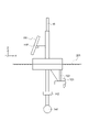
- FIG. 3 is a diagram schematically showing a specific example of the fixed-point observation device 10. As shown in FIG. FIG. 3 mainly shows the appearance of the fixed-point observation device 10, and notation of some of the functional components already explained is omitted.
- the sensor 14 is composed of, for example, a CTD sensor 141 and a current direction/current meter 142 placed at a predetermined water depth.
- the CTD sensor 141 measures the salinity, water temperature, and pressure (water depth) of seawater.
- the current direction and current meter 142 measures the direction and speed of ocean currents.
- the drive unit 13 includes a rudder 132 and a screw 131.
- the rudder 132 is controlled by the return information (distance, azimuth angle) generated by the return information generator 12 .
- the rudder 132 is set to move the fixed-point observation device 10 to the "east” if the azimuth angle of the return information is an angle toward the "east", for example.
- the fixed-point observation device 10 is arranged on the water surface 201, and the drive unit 13 includes a screw 131 that generates propulsive force based on the return information, and a rudder 132 that changes the direction based on the return information.
- the fixed-point observation device 10 can be moved to the position represented by the fixed-point coordinate information (x 0 , y 0 ).
- the screw 131 may be replaced with other propulsion means.
- the rudder 132 may be replaced with direction changing means for changing the direction of a screw 131 (propulsion means), for example.
- the driving unit 13 includes a propulsion unit that generates a propulsive force based on the return information, and a direction change unit that changes the direction based on the return information.
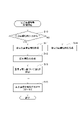
- FIG. 4 is a flow chart showing a schematic operation procedure of the fixed-point observation device 10. As shown in FIG. The operation of the fixed point observation device 10 will be described with reference to FIG.
- the fixed-point observation device 10 measures environmental information at the set observation time.
- the time can be obtained from positioning radio waves received from positioning satellites.
- the coordinate information acquisition unit 11 acquires coordinate information (x 1 , y 1 ) representing its own position using positioning satellites. Then, the return information generator 12 determines whether or not its own position has moved beyond a predetermined distance from a specific position (the position represented by the fixed point coordinate information (x 0 , y 0 )). That is, the return information generator 12 determines whether or not it is within the specified area (step S2).
- step S2 If the user is within the designated area (YES in step S2), the return information generation unit 12 does not generate return information. Therefore, the fixed point observation device 10 does not move.
- the return information generation unit 12 If it is not within the specified area (NO in step S2), the return information generation unit 12 generates return information.
- the drive unit 13 moves the fixed point observation device 10 to the position represented by the fixed point coordinate information (x 0 , y 0 ).
- the fixed point observation device 10 can stay at the position represented by the fixed point coordinate information (x 0 , y 0 ).
- the fixed-point observation device 10 at the position represented by the fixed-point coordinate information (x 0 , y 0 ) measures the environmental information at the observation time, and associates the measured environmental information with the fixed-point coordinate information (x 0 , y 0 ). is stored in the environment information recording unit 17 (step S4).
- the environmental information associated with the fixed-point coordinate information (x 0 , y 0 ) is stored in the environmental information recording unit 17 each time the time reaches the observation time (NO loop of steps S1 to S5).
- the transmission time comes (step S5) the saved environment information is transmitted to the artificial satellite 20 (step S6).
- the artificial satellite 20 relays the environmental information to the receiving device 30.
- the receiving device 30 can always grasp the latest environmental information.
- the fixed point coordinate information (x 0 , y 0 ) may be input in advance by the user, or may be acquired by the fixed point observation device 10 itself.
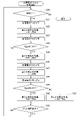
- FIG. 5 is a flowchart showing a processing procedure of fixed-point coordinate movement control performed by the fixed-point observation device 10. As shown in FIG. With reference to FIG. 5, the difference in operation between the case where the user inputs the fixed point coordinate information (x 0 , y 0 ) and the case where the user does not will be described.
- the fixed point observation device 10 determines whether or not the fixed point coordinate information (x 0 , y 0 ) has been input (step S10). "Input completed" means, for example, when the user inputs the fixed point coordinate information (x 0 , y 0 ) before dropping the fixed point observation device 10 on the sea.
- step S10 If input has been completed (YES in step S10), the coordinate information acquisition unit 11 of the fixed-point observation device 10 dropped on the ocean acquires its own coordinate information (x 1 , y 1 ) (step S11).
- the return information generation unit 12 determines the fixed point observation device 10 from the fixed point coordinate information (x 0 , y 0 ) and the fixed point coordinate information (x 0 , y 0 ) based on the fixed point coordinate information (x 0 , y 0 ) and the coordinate information (x 1 , y 1 ). ) is generated (step S12).
- the drive unit 13 moves itself to the position represented by the fixed point coordinate information (x 0 , y 0 ) based on the regression information (step S13).
- the fixed-point observation device 10 stops at the position represented by the fixed-point coordinate information (x 0 , y 0 ) and measures the environmental information.
- the fixed-point observation device 10 can be dropped from anywhere on the ocean at the desired position (fixed-point coordinate information (x 0 , y 0 )) and its movement is automatic.
- step S10 If the fixed-point coordinate information (x 0 , y 0 ) has not been input (NO in step S10), for example, the coordinate information acquisition unit 11 of the fixed-point observation device 10 dropped on the ocean acquires the coordinate information (x 1 , y 1 ) are obtained (step S14).
- the coordinate information (x 1 , y 1 ) in this case is held in the return information generator 12 as fixed point coordinate information (x 0 , y 0 ).
- the above-described processing is performed, and the fixed-point observation device 10 stops at the position represented by the fixed-point coordinate information (x 0 , y 0 ) and measures environmental information.
- the coordinate information acquisition unit 11 may acquire the fixed point coordinate information (x 0 , y 0 ) in this manner. This saves the trouble of inputting the fixed point coordinate information (x 0 , y 0 ). Also, the fixed-point observation device 10 can be placed at any position on the ocean where it was dropped.
- the power generation unit 19 includes a solar cell panel 191, for example.
- the solar cell panel 191 is attached to a pillar protruding in the z-direction via an elevation angle variable section 192 that changes the elevation angle.
- the elevation angle control of the solar panel 191 will be described later.
- the solar panel 191 generates the most power when its front is facing the sun. Therefore, by controlling the solar cell panel 191 so that it always faces the sun, it is possible to increase the amount of power generation.
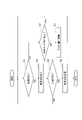
- FIG. 6 is a flow chart showing a processing procedure for controlling the orientation of the solar panel 191. As shown in FIG. Direction control of the solar panel 191 will be described with reference to FIG. Note that FIG. 6 shows a processing procedure after the fixed-point observation device 10 is placed at a specific position (position represented by fixed-point coordinate information (x 0 , y 0 )).
- the power generation unit 19 first determines whether it is daytime (step S20). If it is not daytime (NO in step S20), the power generation unit 19 in this example stops operating.
- the power generation unit 19 acquires the power P1 generated by the solar panel 191 (step S21).
- the drive unit 13 rotates the fixed-point observation device 10 at a specific position by a predetermined angle in one direction (step S22).
- One is clockwise, for example.
- the power generation unit 19 acquires the generated power P2 generated by the solar panel 191 (step S23).
- control unit 21 determines whether or not the generated power P2 is less than P1 (step S24).
- the solar panel 191 is oriented clockwise by a predetermined angle from the front of the sun. Therefore, the fixed-point observation device 10 is rotated in the other direction (counterclockwise) by a predetermined angle (step S25). Then, the solar panel 191 faces the sun.
- the processing after step S25 is a processing procedure for maintaining the orientation of the solar panel 191 facing the sun. A detailed description of the processing procedure for maintaining the orientation is omitted.
- the fixed-point observation device 10 includes the power generation section 19 including the solar panel 191, and the driving section 13 rotates itself at a specific position so that the solar panel 191 faces the sun. Thereby, the power generated by the power generation unit 19 can be maximized.
- the elevation angle of the solar panel 191 may be controlled. Controlling the elevation angle is the same as the process of directing the solar panel 191 toward the front of the sun. Therefore, detailed description is omitted.
- the power generation section 19 includes the elevation angle variable section 192 that changes the elevation angle of the solar panel 191 . Thereby, the power generated by the power generation unit 19 can be maximized.
- FIG. 7 is a block diagram showing a functional configuration example of the receiving device 30 that configures the fixed-point observation system 100 according to this embodiment.
- the receiving device 30 receives environmental information measured by the fixed-point observation device 10 via the artificial satellite 20 and presents it to the user.
- the receiving device 30 includes a satellite receiving section 31, an environment information processing section 32, an output section 33, and a control section . Note that the notation of the power source and the like is omitted.
- the control unit 34 is different in that it controls the overall operation by linking the functional components of the receiving device 30 . Others are the same as the control unit 21 (FIG. 2) described above.
- the satellite reception unit 31 receives environmental information measured by the fixed-point observation device 10 from the artificial satellite 20 .
- the environment information processing unit 32 statistically processes the environment information received from the artificial satellite 20.
- Statistical processing is, for example, processing for calculating statistical information such as the average value, amount of change, and deviation of environmental information.
- the output unit 33 outputs the environment information statistically processed by the environment information processing unit 32 to the outside.
- the output is to display environmental information or the like.
- the fixed-point observation system 100 is a fixed-point observation system that includes a fixed-point observation device 10 that measures environmental information in correspondence with fixed-point coordinate information representing a specific position on the earth, and a receiver that receives the environmental information.
- the observation device 10 has a coordinate information acquisition unit 11 that acquires coordinate information representing its own position using a positioning satellite, and a fixed point coordinate system that detects that its own position has moved beyond a predetermined distance from a specific position.
- a regression information generation unit 12 that detects using information (x 0 , y 0 ) and coordinate information (x 1 , y 1 ) and generates regression information for returning itself to a specific position when detected; , a driving unit 13 that moves itself based on return information, an environment information recording unit 17 that records environment information, and a satellite transmission unit 18 that transmits the environment information to an artificial satellite 20.
- a satellite reception unit 31 for receiving environment information from the satellite 20 is provided. This makes it possible to measure environmental information at a specific position on the earth.
- the fixed-point observation device 10 can measure environmental information in association with fixed-point coordinate information (x 0 , y 0 ) representing a specific position on the earth.
- the fixed-point observation device 10 moves by itself to the position represented by the fixed-point coordinate information (x 0 , y 0 ). Therefore, labor for arranging the fixed-point observation device 10 can be reduced.
- the fixed point coordinate information (x 0 , y 0 ) may be input in advance by the user from the outside, or the input may be omitted. If the input of the fixed point coordinate information (x 0 , y 0 ) is omitted, the position where the fixed point observation device 10 is dropped on the ocean, for example, is at a specific position (the position represented by the fixed point coordinate information (x 0 , y 0 )). Become.
- a part of the fixed-point observation device 10 and the receiving device 30 can be realized by a general-purpose computer system shown in FIG.
- a general-purpose computer system including a CPU 90, a memory 91, a storage 92, a communication unit 93, an input unit 94, and an output unit 95
- the CPU 90 executes a predetermined program loaded on the memory 91 to obtain data.
- Each function of the analysis method selection device 100 is realized.
- the prescribed program can be recorded on computer-readable recording media such as HDD, SSD, USB memory, CD-ROM, DVD-ROM, MO, etc., or can be distributed via a network.
- the fixed-point observation device 10 has been described as an example of a buoy floating on the ocean, but the present invention is not limited to this example.
- the fixed-point observation device 10 may be a flying object that can stop (hover) in the air.
- the fixed point coordinate information also considers the height (z 0 ).
- the height (z 0 ) can be obtained by the coordinate information obtaining section 11 .
- the height (z 0 ) may be considered for a buoy (fixed-point observation device 10) floating on the ocean.
- a buoy fixed-point observation device 10
- three-dimensional fixed point coordinate information (x 0 , y 0 , z 0 ) and coordinate information (x 1 , y 1 , z 1 ) may be used.
- the power generation device included in the power generation section 19 has been shown as an example of the solar cell panel 191, the present invention is not limited to this example.
- the power generation device may be a device for tidal power generation, wave power generation, or the like.
- the fixed-point observation device 10 has been described as an example in which it is placed on the ocean, but the present invention is not limited to this example.
- the fixed-point observation device 10 can obtain the same effect even if it is placed in a lake with a large surface area such as Lake Biwa or Lake Kasumigaura, or in a river or the like.
Landscapes
- Physics & Mathematics (AREA)
- General Physics & Mathematics (AREA)
- Testing Or Calibration Of Command Recording Devices (AREA)
- Position Fixing By Use Of Radio Waves (AREA)
Abstract
地球上のある特定の位置を表す定点座標情報に対応させて環境情報を測定する定点観測装置10であって、自らの位置を表す座標情報を、測位衛星を用いて取得する座標情報取得部11と、自らの位置が、特定の位置から所定の距離を越えて移動した事を、定点座標情報と座標情報とを用いて検出し、該検出した場合に自らを特定の位置に戻すための回帰情報を生成する回帰情報生成部12と、回帰情報に基づいて自らを移動させる駆動部13と、環境情報を記録する環境情報記録部17とを備える。
Description
本発明は、環境モニタリングを行う定点観測装置、定点観測システムに関する。
環境モニタリングは、地球上の何処でも行われる。例えば、海洋の環境モニタリングは、係留ブイ、漂流ブイ、及び水中フロートの何れかの海洋観測装置を用いて海上気象、水中環境をモニタリングする方法が知られている(非特許文献1,2)。
[令和3年4月14日検索]、インターネット<URL:https://www.jamstec.go.jp/j/about/equipment/observe/seawater.html>
[令和3年4月14日検索]、インターネット<URL:https://www.data.jma.go.jp/gmd/kaiyou/db/buoy/buoy-info.html>
係留ブイは、ブイの水没を防ぐために水深より十分長い係留索を用いた係留方式であるスラック係留方式で係留される。スラック係留方式で係留された係留ブイは、設置場所によってはアンカーを中心に数kmも移動する場合がある。また、洋上風力発電機のように特定の位置に固定することは可能であるが、船舶の障害物となるので安易に固定できない。
漂流ブイと水中フロートは、その名の通り、海を漂流しながら環境情報を測定するものである。
このように、従来の海洋観測装置では、地球上のある特定の位置に留まって環境情報を測定することができないという課題がある。
本発明は、この課題に鑑みてなされたものであり、地球上のある特定の位置に留まって環境情報を測定することができる定点観測装置、定点観測システムを提供することを目的とする。
本発明の一態様に係る定点観測装置は、地球上のある特定の位置を表す定点座標情報に対応させて環境情報を測定する定点観測装置であって、自らの位置を表す座標情報を、測位衛星を用いて取得する座標情報取得部と、自らの位置が、前記特定の位置から所定の距離を越えて移動した事を、前記定点座標情報と前記座標情報とを用いて検出し、該検出した場合に自らを前記特定の位置に戻すための回帰情報を生成する回帰情報生成部と、前記回帰情報に基づいて自らを移動させる駆動部と、前記環境情報を記録する環境情報記録部とを備えることを要旨とする。
また、本発明の一態様に係る定点観測システムは、地球上のある特定の座標を表す定点座標情報に対応させて環境情報を測定する定点観測装置と前記環境情報を受信する受信装置とを備える定点観測システムであって、前記定点観測装置は、自らの位置を表す座標情報を、測位衛星を用いて取得する座標情報取得部と、自らの位置が、前記特定の位置から所定の距離を越えて移動した事を、前記定点座標情報と前記座標情報とを用いて検出し、該検出した場合に自らを前記特定の位置に戻すための回帰情報を生成する回帰情報生成部と、前記回帰情報に基づいて自らを移動させる駆動部と、前記環境情報を記録する環境情報記録部と、前記環境情報を人工衛星に送信する衛星送信部とを備え、前記受信装置は、前記人工衛星から前記環境情報を受信する衛星受信部を備えることを要旨とする。
本発明によれば、地球上のある特定の位置に留まって環境情報を測定する定点観測装置、定点観測システムを提供することができる。
以下、本発明の実施形態について図面を用いて説明する。複数の図面中同一のものには同じ参照符号を付し、説明は繰り返さない。
(定点観測システム)
図1は、本発明の実施形態に係る定点観測装置を用いた定点観測システムの構成例を示す構成図である。図1に示す定点観測システム100は、地球上のある特定の位置に配置された定点観測装置で観測した環境情報を、人工衛星を介して受信装置が取得するものである。
図1は、本発明の実施形態に係る定点観測装置を用いた定点観測システムの構成例を示す構成図である。図1に示す定点観測システム100は、地球上のある特定の位置に配置された定点観測装置で観測した環境情報を、人工衛星を介して受信装置が取得するものである。
定点観測システム100は、定点観測装置10、人工衛星20、及び受信装置30を備える。
定点観測装置10の態様は、例えば洋上に浮上して配置されるブイが考えられる。定点観測装置10は、複数あっても構わない。以降の説明は、定点観測装置10は洋上に配置されるブイであり、その数は1個の例で説明する。
人工衛星20は、地球を周回する低軌道衛星、又は静止衛星である。人工衛星20は、定点観測装置10から送信される環境情報を、受信装置30に中継する。
受信装置30は、人工衛星20で中継された環境情報を受信する。そして受信した環境情報を統計処理する。
定点観測システム100によれば、地球上のある特定の位置に配置された定点観測装置10で観測した環境情報を常に把握することができる。次に、定点観測装置10について詳しく説明する。
(定点観測装置)
図2は、定点観測装置10の機能構成例を示すブロック図である。定点観測装置10は、地球上のある特定の位置を表す定点座標情報に対応させて環境情報を測定するものである。
図2は、定点観測装置10の機能構成例を示すブロック図である。定点観測装置10は、地球上のある特定の位置を表す定点座標情報に対応させて環境情報を測定するものである。
定点観測装置10は、座標情報取得部11、回帰情報生成部12、駆動部13、センサ14、センサ駆動部15、センサ情報処理部16、環境情報記録部17、衛星送信部18、発電部19、充電制御部20、制御部21、及び電源部22を備える。
図2に示すように、制御部21は、定点観測装置10の各部の動作を制御する。制御部21、回帰情報生成部12、センサ情報処理部16、環境情報記録部17、及び充電制御部20は、例えばROM、RAM、CPU等からなるコンピュータ(シングルボードコンピュータ)で実現することができる。その場合、その処理内容はプログラムによって記述される。
座標情報取得部11は、自らの位置を表す座標情報を、測位衛星(図示せず)を用いて取得する。測位衛星は、GNSS(全世界測位システム:Global Navigation Satellite System)を構成するものを用いる。
4機の測位衛星を用いて、自らの座標情報(x1,y1,z1)を取得する。この例の場合、定点観測装置10は洋上に配置される。よって、高さを表す座標情報z1は無視してよい。
測位衛星を用いた測位手法は、大きく「単独測位」と「相対測位」に分けられる。高精度な測位が可能な「相対測位」は基準局が必要である。基準局が存在しない洋上等では「単独測位」を用いる。「単独測位」でも10m程度の測位精度が得られる。
回帰情報生成部12は、自らの位置が、特定の位置から所定の距離を越えて移動したことを、定点座標情報(x0,y0)と座標情報(x1,y1)とを用いて検出し、該検出した場合に自らを特定の位置に戻すための回帰情報を生成する。定点座標情報(x0,y0)は、予め利用者が入力してもよいし、座標情報取得部11で測定するようにしてもよい。
所定の距離は、測位精度が10m程度であると仮定すると、例えば20mに設定する。測位精度が高ければ1m単位で所定の距離を設定することも可能である。
回帰情報は、定点座標情報で表される位置に定点観測装置10を移動させるための情報であり、距離と方位角の2つの情報を含む。2つの座標間((x0,y0)-(x1,y1))の距離と方位角は、周知の計算方法(例えば、国土地理院:測量計算サイト)で求めることができる。
駆動部13は、回帰情報に基づいて自らを移動させる。駆動部13は、回帰情報に含まれる距離情報が例えば1kmである場合、その距離情報が0になるまで方位角の方向に自らを移動させる。
センサ14は、例えば、海水の塩分、水温、圧力(水深)を計測するCTDセンサである。また、水中に限らず海上の環境情報も測定する。例えば、温度湿度計、風速計等を備えてもよい。また、周囲を撮影するカメラを備えてもよい。
センサ駆動部15は、センサ14を駆動すると共にセンサ14から環境情報を取得する。センサ駆動部15は、センサ14を駆動するいわゆるドライバーである。
センサ情報処理部16は、センサ駆動部15が出力する環境情報を、定点座標情報(x0,y0)に対応付ける。また、センサ情報処理部16は、環境情報を統計処理してもよい。統計処理は、例えば環境情報の平均値等を求める処理である。
環境情報記録部17は、センサ情報処理部16で定点座標情報(x0,y0)に対応付けられた環境情報を記録する。環境情報記録部17は、例えば上記のRAMで構成される。
衛星送信部18は、環境情報記録部17に記録された環境情報を、人工衛星20に送信する。人工衛星20は、環境情報を受信装置30に中継する。
発電部19は、定点観測装置10を動作させるための電力を発電する。発電部19は、例えば太陽電池パネル等の発電デバイスを含む。
充電制御部20は、発電部19が発電した電力を電源部22に蓄える。充電制御部20は、電源部22が過充電及び過放電にならないように充電を制御する。
電源部22は、例えばリチウム二次電池である。電源部22は、定点観測装置10の各部に電力を供給する。
発電部19と充電制御部20は、電源部22の容量が十分大きければ無くても構わない。また、衛星送信部18も無くてもよい。つまり、衛星送信部18は、環境情報記録部17に記録された環境情報を、定点観測装置10から直接取得できれば不要である。
以上説明したように、本実施形態に係る定点観測装置10は、地球上のある特定の位置を表す定点座標情報(x0,y0)に対応させて環境情報を測定する定点観測装置であって、自らの位置を表す座標情報(x1,y1)を、測位衛星を用いて取得する座標情報取得部11と、座標情報(x1,y1)が、定点座標情報(x0,y0)から所定の距離を越えて移動した事を、定点座標情報(x0,y0)と座標情報(x1,y1)とを用いて検出し、該検出した場合に自らを特定の位置に戻すための回帰情報を生成する回帰情報生成部12と、回帰情報に基づいて自らを移動させる駆動部13と、環境情報を記録する環境情報記録部17とを備える。これにより、定点観測装置10は、地球上のある特定の位置(定点座標情報(x0,y0)で表される位置)に留まって環境情報を測定することができる。
(定点観測装置の具体例)
図3は、定点観測装置10の具体例を模式的に示す図である。図3は、主に定点観測装置10の外観を示し、説明済みの一部の機能構成部の表記は省略している。
図3は、定点観測装置10の具体例を模式的に示す図である。図3は、主に定点観測装置10の外観を示し、説明済みの一部の機能構成部の表記は省略している。
図3の右をX方向、奥行きをY方向、上下をZ方向と定義する。図3に示すように、定点観測装置10は、X-Y平面(水面201)に浮かぶ移動可能なブイである。
定点観測装置10は、水面201より上に発電部19、水面201より下にセンサ14と駆動部13を備える。発電部19については後述する。
センサ14は、例えば、所定の水深に配置されるCTDセンサ141と流向流速計142で構成される。CTDセンサ141は、海水の塩分、水温、圧力(水深)を計測する。流向流速計142は、海流の流れる方向、速さを計測する。
また、駆動部13は、方向舵132とスクリュー131を備える。方向舵132は、回帰情報生成部12が生成する回帰情報(距離、方位角)によって制御される。方向舵132は、回帰情報の方位角が例えば「東」に向かう角度であれば、定点観測装置10を「東」に移動させる向きに設定される。
スクリュー131は、回帰情報の距離を表す距離情報によって制御される。距離が大きければスクリューは速く回転し、距離が無くなれば停止する。
このように、定点観測装置10は水面201に配置され、駆動部13は、回帰情報に基づいて推進力を発生させるスクリュー131と、回帰情報に基づいて方向を変化させる方向舵132とを備える。これにより定点観測装置10を、定点座標情報(x0,y0)で表される位置に移動させることができる。
なお、スクリュー131は、他の推進手段に代えてもよい。また、方向舵132は、例えばスクリュー131等(推進手段)の方向を変える方向変更手段に代えてもよい。つまり、駆動部13は、回帰情報に基づいて推進力を発生させる推進手段と、回帰情報に基づいて方向を変更させる方向変更手段とを備える。
また、定点観測装置10は、周囲の障害物を検知する障害物検知部23(図示せず)を備えてもよい。障害物検知部23は、例えば定点観測装置10の周囲を撮影する撮影装置である。制御部21は、障害物検知部23で撮影した画像から障害物を検知し、障害物と衝突しないように駆動部13を制御する。これにより、定点観測装置10と障害物との衝突を回避することができる。
(動作)
図4は、定点観測装置10の概略の動作手順を示すフローチャートである。図4を参照して定点観測装置10の動作を説明する。
図4は、定点観測装置10の概略の動作手順を示すフローチャートである。図4を参照して定点観測装置10の動作を説明する。
定点観測装置10は、設定された観測時刻になると環境情報を測定する。時刻は、測位衛星から受信する測位電波から取得できる。
観測時刻にならないと(ステップS1のNO)、座標情報取得部11は、自らの位置を表す座標情報(x1,y1)を、測位衛星を用いて取得する。そして、回帰情報生成部12は、自らの位置が、特定の位置(定点座標情報(x0,y0)で表される位置)から所定の距離を越えて移動していないかを判定する。つまり、回帰情報生成部12は、自らが指定エリア内に在るか否かを判定する(ステップS2)。
自らが指定エリア内に在る場合(ステップS2のYES)、回帰情報生成部12は回帰情報を生成しない。よって、定点観測装置10は移動しない。
自らが指定エリア内に無い場合(ステップS2のNO)、回帰情報生成部12は回帰情報を生成する。回帰情報が生成されると、駆動部13は定点座標情報(x0,y0)で表される位置に定点観測装置10を移動させる。
ステップS1~S3の処理を繰り返すことで、定点観測装置10は、定点座標情報(x0,y0)で表される位置に留まることができる。
定点座標情報(x0,y0)で表される位置の定点観測装置10は、観測時刻になると環境情報を測定し、測定した環境情報を定点座標情報(x0,y0)に対応付けて環境情報記録部17に保存する(ステップS4)。
定点座標情報(x0,y0)に対応付けられた環境情報は、時刻が観測時刻になる度に環境情報記録部17に保存される(ステップS1~S5のNOのループ)。保存された環境情報は、送信時刻が来ると(ステップS5)、人工衛星20に送信される(ステップS6)。
人工衛星20は、環境情報を受信装置30に中継する。受信装置30は、最新の環境情報を常に把握することができる。
定点座標情報(x0,y0)は、予め利用者が入力してもよいし、定点観測装置10が自ら取得してもよい。
図5は、定点観測装置10が行う定点座標移動制御の処理手順を示すフローチャートである。図5を参照して、定点座標情報(x0,y0)を利用者が入力する場合と、そうでない場合の動作の違いについて説明する。
定点観測装置10は、動作を開始すると、定点座標情報(x0,y0)が入力済みであるか否かを判定する(ステップS10)。入力済みとは、例えば、定点観測装置10を洋上に投下する前に、利用者が定点座標情報(x0,y0)を入力した場合である。
入力済みの場合(ステップS10のYES)、洋上に投下された定点観測装置10の座標情報取得部11は、自らの座標情報(x1,y1)を取得する(ステップS11)。
次に回帰情報生成部12は、定点座標情報(x0,y0)と座標情報(x1,y1)の2つの座標情報から、定点観測装置10を定点座標情報(x0,y0)で表される座標まで移動させる回帰情報を生成する(ステップS12)。
次に駆動部13は、回帰情報に基づいて自らを定点座標情報(x0,y0)で表される位置まで移動させる(ステップS13)。
その後、図4で説明済みのステップS1~S3の処理を繰り返すことで、定点観測装置10は定点座標情報(x0,y0)で表される位置に止まり、環境情報を測定する。
このように、定点座標情報(x0,y0)は、利用者が外部から入力する場合、定点観測装置10は、洋上のどこから投下しても所望の位置(定点座標情報(x0,y0)で表される位置)に配置され、その移動は自動的に行われる。
定点座標情報(x0,y0)が入力されていない場合(ステップS10のNO)、例えば洋上に投下された定点観測装置10の座標情報取得部11は、自らの位置を表す座標情報(x1,y1)を取得する(ステップS14)。この場合の座標情報(x1,y1)は、定点座標情報(x0,y0)として回帰情報生成部12に保持される。以降は、上記の説明済みの処理が行われ、定点観測装置10は、定点座標情報(x0,y0)で表される位置に止まり、環境情報を測定する。
このように定点座標情報(x0,y0)は、座標情報取得部11が取得してもよい。これにより、定点座標情報(x0,y0)を入力する手間を省くことができる。また、定点観測装置10を、投下した洋上の任意の位置に配置することができる。
(発電部)
図3に示したように、発電部19は、例えば太陽電池パネル191を備える。太陽電池パネル191は、その仰角を変化させる仰角可変部192を介してz方向に突出した支柱に取付けられている。太陽電池パネル191の仰角制御については後述する。
図3に示したように、発電部19は、例えば太陽電池パネル191を備える。太陽電池パネル191は、その仰角を変化させる仰角可変部192を介してz方向に突出した支柱に取付けられている。太陽電池パネル191の仰角制御については後述する。
太陽電池パネル191は、その正面を太陽に向けた場合に最も多く発電する。よって、太陽電池パネル191を常に太陽に向くように制御することで、発電量を大きくすることができる。
図6は、太陽電池パネル191の向きを制御する処理手順を示すフローチャートである。図6を参照して太陽電池パネル191の方向制御について説明する。なお、図6は、定点観測装置10が特定の位置(定点座標情報(x0,y0)で表される位置)に配置された後の処理手順を示す。
発電部19は、最初に昼間か否かを判定する(ステップS20)。昼間で無い場合(ステップS20のNO)、この例の発電部19は動作を停止する。
昼間である場合(ステップS20のYES)、発電部19は、太陽電池パネル191が発電する発電電力P1を取得する(ステップS21)。
次に、駆動部13は、特定の位置の定点観測装置10を所定の角度、一方に回転させる(ステップS22)。一方は例えば時計方向である。
次に、発電部19は、太陽電池パネル191が発電する発電電力P2を取得する(ステップS23)。
次に、制御部21は、発電電力P2がP1より減少しているか否かを判定する(ステップS24)。
発電電力P2が減少していない場合(ステップS24のNO)、ステップS21~S24の処理を繰り返し、発電電力P2がP1より小さくなるまで、例えば時計方向に所定の角度ずつ定点観測装置10を回転させる(ステップS24のNOのループ)。
発電電力P2がP1より小さくなる(ステップS24のYES)と、太陽電池パネル191は太陽の正面から、時計方向に所定の角度ずれた向きである。そこで、定点観測装置10を他方(反時計方向)に所定の角度を回転させて戻す(ステップS25)。そうすると、太陽電池パネル191は、太陽に正面を向けることになる。
この結果、太陽電池パネル191は最大電力を発電する。ステップS25以降の処理は、太陽に正面を向けた太陽電池パネル191の向きを維持するための処理手順である。
向きを維持するための処理手順についての詳しい説明は省略する。
向きを維持するための処理手順についての詳しい説明は省略する。
このように、定点観測装置10は、太陽電池パネル191を含む発電部19を備え、駆動部13は、太陽電池パネル191が太陽に向くように、特定の位置で自らを回転させる。これにより、発電部19の発電電力を最大化することができる。
なお、太陽電池パネル191の仰角を制御するようにしてもよい。仰角の制御は、太陽電池パネル191を太陽の正面に向ける処理と同じである。よって、詳しい説明は省略する。このように発電部19は、太陽電池パネル191の仰角を変化させる仰角可変部192を備える。これにより、発電部19の発電電力を最大化することができる。
(受信装置)
図7は、本実施形態に係る定点観測システム100を構成する受信装置30の機能構成例を示すブロック図である。受信装置30は、定点観測装置10で測定した環境情報を、人工衛星20を介して受信し利用者に提示するものである。
図7は、本実施形態に係る定点観測システム100を構成する受信装置30の機能構成例を示すブロック図である。受信装置30は、定点観測装置10で測定した環境情報を、人工衛星20を介して受信し利用者に提示するものである。
図7に示すように、受信装置30は、衛星受信部31、環境情報処理部32、出力部33、及び制御部34を備える。なお、電源部等の表記は省略している。
制御部34は、受信装置30の各機能構成部の間を連携させて全体の動作を制御する点で異なる。その他は、上記の制御部21(図2)と同じである。
衛星受信部31は、人工衛星20から、定点観測装置10で測定した環境情報を受信する。
環境情報処理部32は、人工衛星20から受信した環境情報を統計処理する。統計処理は、例えば、環境情報の平均値、変化量、偏差等の統計情報を計算する処理である。
出力部33は、環境情報処理部32で統計処理した環境情報を外部に出力する。出力は、環境情報を表示等することである。
定点観測システム100は、地球上のある特定の位置を表す定点座標情報に対応させて環境情報を測定する定点観測装置10と環境情報を受信する受信装置とを備える定点観測システムであって、定点観測装置10は、自らの位置を表す座標情報を、測位衛星を用いて取得する座標情報取得部11と、自らの位置が、特定の位置から所定の距離を越えて移動したことを、定点座標情報(x0,y0)と座標情報(x1,y1)とを用いて検出し、該検出した場合に自らを特定の位置に戻すための回帰情報を生成する回帰情報生成部12と、回帰情報に基づいて自らを移動させる駆動部13と、環境情報を記録する環境情報記録部17と、環境情報を人工衛星20に送信する衛星送信部18とを備え、受信装置30は、人工衛星20から環境情報を受信する衛星受信部31を備える。これにより、地球上のある特定の位置の環境情報を測定することができる。
以上説明したように、本実施形態に係る定点観測装置10は、地球上のある特定の位置を表す定点座標情報(x0,y0)に対応させて環境情報を測定することができる。定点観測装置10は、定点座標情報(x0,y0)で表される位置に自ら移動する。よって、定点観測装置10を配置する労力を軽減することができる。
定点座標情報(x0,y0)は、利用者が予め外部から入力してもよいし、その入力を省略してもよい。定点座標情報(x0,y0)の入力を省略した場合、定点観測装置10を例えば洋上に投下した位置が特定の位置(定点座標情報(x0,y0)で表される位置)になる。
定点観測装置10及び受信装置30の一部(制御部21等)は、図8に示す汎用的なコンピュータシステムで実現することができる。例えば、CPU90、メモリ91、ストレージ92、通信部93、入力部94、及び出力部95を備える汎用的なコンピュータシテムにおいて、CPU90がメモリ91上にロードされた所定のプログラムを実行することにより、データ分析方法選択装置100の各機能が実現される。所定のプログラムは、HDD、SSD、USBメモリ、CD-ROM、DVD-ROM、MOなどのコンピュータ読取り可能な記録媒体に記録することも、ネットワークを介して配信することもできる。
上記の実施形態では、定点観測装置10を例えば洋上に浮かぶブイの例で説明したが、は、本発明はこの例に限定されない。定点観測装置10は、空中に停止(ホバリング)できる飛行体であっても構わない。飛行体である場合、定点座標情報は高さ(z0)も考慮する。高さ(z0)は、座標情報取得部11で取得することができる。
また、高さ(z0)は、洋上に浮かぶブイ(定点観測装置10)でも考慮してよい。例えば、潮位等による高さを考慮する場合は、3次元の定点座標情報(x0,y0,z0)と座標情報(x1,y1,z1)を用いればよい。
また、発電部19が備える発電デバイスは太陽電池パネル191の例を示したが、本発明はこの例に限定されない。発電デバイスは、潮流発電、波力発電等のデバイスであっても構わない。
また、定点観測装置10は、洋上に配置する例で説明したが、本発明はこの例に限定されない。定点観測装置10は、琵琶湖、霞ケ浦等の大きな表面積の湖、又は河川等に配置しても同じ作用効果が得られる。
このように、本発明はここでは記載していない様々な実施形態等を含むことは勿論である。したがって、本発明の技術的範囲は上記の説明から妥当な特許請求の範囲に係る発明特定事項によってのみ定められるものである。
10:定点観測装置
11:座標情報取得部
12:回帰情報生成部
13:駆動部
17:環境情報記録部
18:衛星送信部
19:発電部
20:人工衛星
30:受信装置
31:衛星受信部
131:スクリュー
132:方向舵
191:太陽電池パネル
192:仰角可変部
11:座標情報取得部
12:回帰情報生成部
13:駆動部
17:環境情報記録部
18:衛星送信部
19:発電部
20:人工衛星
30:受信装置
31:衛星受信部
131:スクリュー
132:方向舵
191:太陽電池パネル
192:仰角可変部
Claims (8)
- 地球上のある特定の位置を表す定点座標情報に対応させて環境情報を測定する定点観測装置であって、
自らの位置を表す座標情報を、測位衛星を用いて取得する座標情報取得部と、
自らの位置が、前記特定の位置から所定の距離を越えて移動した事を、前記定点座標情報と前記座標情報とを用いて検出し、該検出した場合に自らを前記特定の位置に戻すための回帰情報を生成する回帰情報生成部と、
前記回帰情報に基づいて自らを移動させる駆動部と、
前記環境情報を記録する環境情報記録部と
を備える定点観測装置。 - 前記定点座標情報は、利用者が外部から入力する
請求項1に記載の定点観測装置。 - 前記定点座標情報は、前記座標情報取得部が取得する
請求項1に記載の定点観測装置。 - 前記定点観測装置は水面に配置され、
前記駆動部は、
前記回帰情報に基づいて推進力を発生させる推進手段と、
前記回帰情報に基づいて方向を変更させる方向変更手段と
を備える請求項1乃至3の何れかに記載の定点観測装置。 - 障害物を検知する障害物検知部を備え、
前記駆動部は、
前記障害物との衝突を回避するように自らを移動させる請求項4に記載の定点観測装置。 - 太陽電池パネルを含む発電部を備え、
前記駆動部は、
前記太陽電池パネルが太陽に向くように、前記特定の位置で自らを回転させる
請求項4又は5に記載の定点観測装置。 - 前記発電部は、
前記太陽電池パネルの仰角を変化させる仰角可変部を
備える請求項6に記載の定点観測装置。 - 地球上のある特定の座標を表す定点座標情報に対応させて環境情報を測定する定点観測装置と前記環境情報を受信する受信装置とを備える定点観測システムであって、
前記定点観測装置は、
自らの位置を表す座標情報を、測位衛星を用いて取得する座標情報取得部と、
自らの位置が、前記特定の位置から所定の距離を越えて移動した事を、前記定点座標情報と前記座標情報とを用いて検出し、該検出した場合に自らを前記特定の位置に戻すための回帰情報を生成する回帰情報生成部と、
前記回帰情報に基づいて自らを移動させる駆動部と、
前記環境情報を記録する環境情報記録部と、
前記環境情報を人工衛星に送信する衛星送信部と
を備え、
前記受信装置は、
前記人工衛星から前記環境情報を受信する衛星受信部
を備える定点観測システム。
Priority Applications (2)
| Application Number | Priority Date | Filing Date | Title |
|---|---|---|---|
| JP2023520653A JP7560787B2 (ja) | 2021-05-12 | 2021-05-12 | 定点観測装置、定点観測システム |
| PCT/JP2021/018039 WO2022239145A1 (ja) | 2021-05-12 | 2021-05-12 | 定点観測装置、定点観測システム |
Applications Claiming Priority (1)
| Application Number | Priority Date | Filing Date | Title |
|---|---|---|---|
| PCT/JP2021/018039 WO2022239145A1 (ja) | 2021-05-12 | 2021-05-12 | 定点観測装置、定点観測システム |
Publications (1)
| Publication Number | Publication Date |
|---|---|
| WO2022239145A1 true WO2022239145A1 (ja) | 2022-11-17 |
Family
ID=84028543
Family Applications (1)
| Application Number | Title | Priority Date | Filing Date |
|---|---|---|---|
| PCT/JP2021/018039 Ceased WO2022239145A1 (ja) | 2021-05-12 | 2021-05-12 | 定点観測装置、定点観測システム |
Country Status (2)
| Country | Link |
|---|---|
| JP (1) | JP7560787B2 (ja) |
| WO (1) | WO2022239145A1 (ja) |
Cited By (1)
| Publication number | Priority date | Publication date | Assignee | Title |
|---|---|---|---|---|
| WO2026013997A1 (ja) * | 2024-07-10 | 2026-01-15 | Ntt株式会社 | 観測システム |
Citations (3)
| Publication number | Priority date | Publication date | Assignee | Title |
|---|---|---|---|---|
| JP2002186957A (ja) * | 2000-10-13 | 2002-07-02 | Keiichi Sugino | 水処理方法および水処理装置 |
| JP2009143331A (ja) * | 2007-12-13 | 2009-07-02 | Hitachi Zosen Corp | 津波・波浪観測用ブイ |
| JP2017178242A (ja) * | 2016-03-31 | 2017-10-05 | 株式会社 神崎高級工機製作所 | 操船システム及び船舶 |
-
2021
- 2021-05-12 JP JP2023520653A patent/JP7560787B2/ja active Active
- 2021-05-12 WO PCT/JP2021/018039 patent/WO2022239145A1/ja not_active Ceased
Patent Citations (3)
| Publication number | Priority date | Publication date | Assignee | Title |
|---|---|---|---|---|
| JP2002186957A (ja) * | 2000-10-13 | 2002-07-02 | Keiichi Sugino | 水処理方法および水処理装置 |
| JP2009143331A (ja) * | 2007-12-13 | 2009-07-02 | Hitachi Zosen Corp | 津波・波浪観測用ブイ |
| JP2017178242A (ja) * | 2016-03-31 | 2017-10-05 | 株式会社 神崎高級工機製作所 | 操船システム及び船舶 |
Cited By (1)
| Publication number | Priority date | Publication date | Assignee | Title |
|---|---|---|---|---|
| WO2026013997A1 (ja) * | 2024-07-10 | 2026-01-15 | Ntt株式会社 | 観測システム |
Also Published As
| Publication number | Publication date |
|---|---|
| JP7560787B2 (ja) | 2024-10-03 |
| JPWO2022239145A1 (ja) | 2022-11-17 |
Similar Documents
| Publication | Publication Date | Title |
|---|---|---|
| US11486346B1 (en) | Autonomous underwater beacon locator | |
| US5894450A (en) | Mobile underwater arrays | |
| Evans et al. | Docking techniques and evaluation trials of the SWIMMER AUV: an autonomous deployment AUV for work-class ROVs | |
| EP4309994A1 (en) | System for coupling aquatic relay machine and underwater cruising body, and operation method therefor | |
| Aoki et al. | Advanced technologies for cruising AUV Urashima | |
| Jung et al. | A study on unmanned surface vehicle combined with remotely operated vehicle system | |
| Behrje et al. | A robust acoustic-based communication principle for the navigation of an underwater robot swarm | |
| CN104019803A (zh) | 基于双船模式的水域、滩涂及岸坡地理空间信息测量平台 | |
| CN117470307A (zh) | 海底电缆巡检方法、装置、计算机设备和存储介质 | |
| CN204269114U (zh) | 基于双船模式的水域、滩涂及岸坡地理空间信息测量平台 | |
| JP2002250766A (ja) | 水中曳航体測位方法及びシステム | |
| CN114047515A (zh) | 基于无人船的侧扫声呐系统及侧扫声呐设备数据处理方法 | |
| JP7560787B2 (ja) | 定点観測装置、定点観測システム | |
| JPH1090017A (ja) | 海面定点を浮遊する多目的ポッド | |
| Watanabe et al. | Development of a floating LBL system and a lightweight ROV for sky to water system | |
| Ma et al. | Integration of multi-sensor marine environment monitoring system for hybrid-power USV | |
| Hyakudome et al. | Key technologies for AUV" URASHIMA" | |
| Choi et al. | Autonomous towed vehicle for underwater inspection in a port area | |
| CN111427010A (zh) | Rov水下定位系统及定位方法 | |
| Arzamendia et al. | An autonomous surface vehicle for water quality measurements in a lake using MQTT protocol | |
| CN116559775A (zh) | 一种水下定位潜标及水下定位系统 | |
| KR20230086369A (ko) | 해양 발전소의 구조물 모니터링을 위한 무인수상선의 제어 장치 및 방법 | |
| JP7794514B1 (ja) | 災害観測システム、災害観測方法およびプログラム | |
| US20240308632A1 (en) | Linked system of surface repeater vehicle and underwater vehicle, and operation method therefor | |
| JP7251875B2 (ja) | ソナーシステム、位置ずれ検出方法及びプログラム |
Legal Events
| Date | Code | Title | Description |
|---|---|---|---|
| 121 | Ep: the epo has been informed by wipo that ep was designated in this application |
Ref document number: 21941879 Country of ref document: EP Kind code of ref document: A1 |
|
| WWE | Wipo information: entry into national phase |
Ref document number: 2023520653 Country of ref document: JP |
|
| NENP | Non-entry into the national phase |
Ref country code: DE |
|
| 122 | Ep: pct application non-entry in european phase |
Ref document number: 21941879 Country of ref document: EP Kind code of ref document: A1 |