WO2022239063A1 - 制御装置、方法及びプログラム - Google Patents
制御装置、方法及びプログラム Download PDFInfo
- Publication number
- WO2022239063A1 WO2022239063A1 PCT/JP2021/017699 JP2021017699W WO2022239063A1 WO 2022239063 A1 WO2022239063 A1 WO 2022239063A1 JP 2021017699 W JP2021017699 W JP 2021017699W WO 2022239063 A1 WO2022239063 A1 WO 2022239063A1
- Authority
- WO
- WIPO (PCT)
- Prior art keywords
- unit
- control object
- object unit
- head
- control
- Prior art date
- Legal status (The legal status is an assumption and is not a legal conclusion. Google has not performed a legal analysis and makes no representation as to the accuracy of the status listed.)
- Ceased
Links
Images






Classifications
-
- G—PHYSICS
- G05—CONTROLLING; REGULATING
- G05D—SYSTEMS FOR CONTROLLING OR REGULATING NON-ELECTRIC VARIABLES
- G05D1/00—Control of position, course, altitude or attitude of land, water, air or space vehicles, e.g. using automatic pilots
Definitions
- the present invention relates to technology for controlling the actions of multiple controlled objects.
- Non-Patent Document 1 a plurality of cubic robots extend and contract with each other (a robot moves while expanding and contracting while being in contact with another robot). Robot platoon deformation by is handled.
- Non-Patent Document 2 and Patent Document 1 it is assumed that the robots are in contact with each other. Each robot is assumed to be the same (homogeneous), and platoon control is realized when the target position of each robot within the target form is not determined.
- the transformation of robot platoons by plane shearing motion between multiple cubic robots (movement of a robot sliding on the contacting surface while in contact with another robot) is dealt with. It is applicable even if there is a disconnection point in the intersection of the set of platoon positions taken by the robot in the initial state and the set of target positions of the robot.
- Non-Patent Document 2 and Patent Document 1 it is possible that the time required for platoon deformation is long.
- the present invention is to provide a control device, method, and program that can change platoons in a shorter time than before.
- a control device is a control device for moving a plurality of control object units at a predetermined initial position S to a predetermined target position G, wherein each control object unit has a plurality of control object units.
- the connectivity of the controlled object structure is defined as the fact that each controlled object unit is adjacent to another controlled object unit to form a group of controlled object structures.
- a head control object unit selection unit that selects, as a head control object unit Head, the head control object unit that has the smallest Manhattan distance in the partial target position area A GS ⁇ Gi from the entrance position Ei from among the head control object units in the head control object unit; a target position selection unit that selects a position that is in contact with the target object unit Head and where no control target object unit exists in the partial target position area A GS ⁇ Gi as the target position D and adds it to the set Up; A tail controlled object that selects, as a tail controlled object unit Tail, one having the largest Manhattan distance in the partial initial position area A SS ⁇ Gj from the entrance position Ei among the control object units in the partial initial position area A SS ⁇ Gj .
- a motion plan determination unit that determines a motion plan for moving the leading controlled object unit Head to the target position D and following the motion of the leading controlled object unit; In the drawing, two positions at which voids are generated are determined among the positions of the control object constituting a series of control object units, and the determined two positions and the leading direction adjacent to the determined two positions are determined.
- control object A set addition unit that adds all the positions of the controlled object units that are connected from the object unit to the target position G to the set Up, a head controlled object unit selection unit, a target position selection unit, and a tail controlled object A repeat control unit that repeats the processing of the object unit selection unit and the operation plan determination unit until all the control object units can move to the target position according to the operation plan, and the control unit according to the determined operation plan. and a moving unit that moves the target unit.
- a control device is a control device for moving a plurality of control object units at a predetermined initial position S to a predetermined target position G, wherein each control object unit has a plurality of control object units.
- the connectivity of the controlled object structure is defined as the fact that each controlled object unit is adjacent to another controlled object unit to form a group of controlled object structures.
- a head control object unit selection unit that selects, as a head control object unit Head, the head control object unit that has the smallest Manhattan distance in the partial target position area A GS ⁇ Gi from the entrance position Ei from among the head control object units in the head control object unit; a target position selection unit that selects a position that is in contact with the target object unit Head and where no control target object unit exists in the partial target position area A GS ⁇ Gi as the target position D and adds it to the set Up; A tail controlled object that selects, as a tail controlled object unit Tail, one having the largest Manhattan distance in the partial initial position area A SS ⁇ Gj from the entrance position Ei among the control object units in the partial initial position area A SS ⁇ Gj .
- a motion plan determination unit that determines a motion plan for moving the leading controlled object unit Head to the target position D and following the motion of the leading controlled object unit;
- the void for moving the series of controlled object units does not overlap with the void for moving the series of controlled object units that moved one time earlier.
- the void for moving the series of controlled object units By determining the waiting time for the movement of a series of control object units so that they do not overlap, it is possible to change the formation in a shorter time than before.
- FIG. 4 is a diagram for explaining an initial position and a target position for each controlled object;
- FIG. 4 is a diagram for explaining how voids move;
- FIG. 4 is a diagram for explaining an example of control target units;
- FIG. 11 is a diagram for explaining a method of calculating a time difference between each turning step operation start;
- FIG. 3 is a diagram for explaining an example of a control device;
- FIG. 4 is a diagram for explaining an example of a control method;
- FIG. 2 is a diagram for showing an example of the functional configuration of a computer;
- FIG. 1 illustrates, for example, a mission in which a large number of controlled objects cooperate to move while maintaining contact with each controlled object, and transform the platoon from the initial position to the target position.
- the use of such a cubic controlled object that can be moved by sliding the surfaces that are in contact with each other is assumed. As shown in FIG. 2, this is realized by moving a plurality of controlled objects from initial positions to target positions in a room partitioned by walls (walls are omitted in the drawing).
- another object to be controlled exists in one of the six squares in the vertical, horizontal, and height directions around the object to be controlled (hereinafter also referred to as "up, down, left, right, front, and rear directions"). It shall move while maintaining the state where it is.
- This method has the advantage that one controlled object itself moves a distance corresponding to the size of one controlled object, so that the movement amount of one operation can be accurately measured.
- the position of each controlled object in the entire group of controlled objects can be easily known. For this reason, it is difficult to cause a problem that the formation is broken due to an error in the amount of movement of the controlled object.
- Each cube in FIG. 1 indicates the position of each controlled object. Only one controlled object can exist in each cube. Each controlled object is assumed to be stationary if there is an obstacle or other controlled object in the direction in which it intends to move.
- a cubic space in which a controlled object can exist is also called a mass or a grid.
- dark gray squares indicate positions where control objects exist.
- the positions where the controlled objects exist in FIG. 2A indicate a set of initial positions of the controlled objects, and the positions where the controlled objects exist in FIG.
- each initial position and each target position are adjacent to other initial positions and target positions in at least one of the vertical and horizontal directions, respectively, and the platoon shape at the initial position and target position of the control object is Each is a lump of arbitrary shape.
- each state of the controlled object i (the position and behavior of the controlled object) is represented by a discrete value.
- each position is expressed by values obtained by discretely expressing the X, Y, and Z axes. That is, the room (three-dimensional space) is partitioned by grids, and each grid corresponds to each position. Also, in each grid, "presence/absence" of obstacles is set in advance.
- the subject of action is each controlled object arranged in the room.
- the action a of the controlled object i takes one of 7 types of movement, i.e., resting and moving in the vertical, horizontal and height directions by one grid.
- the search calculation when incorporating the constraint condition that the controlled objects are in contact with each other, the search calculation must be performed after considering the mutual movement of the controlled objects. Moreover, it is difficult to fundamentally reduce the amount of calculation, which is a big problem when using multiple controlled objects.
- Non-Patent Document 2 Homogeneous platoon control in Non-Patent Document 2 introduces the concept of void control as one of the measures for solving the above-described problem of computational load. In addition, in order to overcome the platoon deformation problem described in [Problem setting], the idea of 8 control object units is introduced.
- the void here means a gap that is formed at the original position after a certain controlled object moves to another position.
- a void is a virtual entity that moves in the direction opposite to the direction in which the controlled object moves.
- the motion planning problem of the controlled object can be considered as a single void motion plan, which is suitable for reducing the search computation load.
- each controlled object belonging to the controlled object unit becomes scattered during the deformation operation and is divided into different controlled object units, and the load when the subsequent controlled object replacement operation is required. It also led to an increase. Moreover, it is not applicable when the initial position and the target position have a common portion and the common portion is divided into a plurality of non-connected portions.
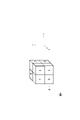
- control object unit [Introduction of 8 mass control object units] Therefore, as shown in FIG. 4, eight adjacent control objects are treated as one unit (control object unit), and the control object moves while maintaining this control object unit.
- eight controlled objects constitute one controlled object unit, and each of the eight controlled objects constituting one controlled object unit can be controlled in three directions to form one controlled object unit. Move while maintaining a state adjacent to the object.
- This group of control object units is controlled so that each control object unit shares one surface and moves while being in contact with each other. Assume that all controlled objects are identical and homogeneous.
- a control object unit formed by eight control objects is a unit of one mass (in this embodiment, this unit is hereinafter also referred to as a "mass unit” or a “position unit”).
- this unit is hereinafter also referred to as a "mass unit” or a "position unit”).
- the initial position of each controlled object is (Xr_u0[j], Yr_u0[j], Zr_u0[j]) and the target position is (Xr_ue[j], Yr_ue[j], Zr_ue[j]).
- the total number p of control objects is assumed to be a multiple of eight.
- the control target unit may be configured to satisfy the following conditions. That is, the control object unit is (1) a cube having a length M (M ⁇ 2, where the length of one control object is defined as length 1) in each axial direction in a three-dimensional orthogonal coordinate system. It is a structure forming a shape space (hereinafter referred to as a metamodule), and includes (2) a structure in which M controlled objects are adjacent in each axial direction.
- control object unit a structure composed of eight control objects shown in FIG. 4 will be described as a control object unit. A similar effect can be obtained if the control object unit is configured to satisfy the above conditions (1) and (2) within the module.
- each controlled object unit j From a state in which each controlled object unit j exists at an arbitrary position in the set S of initial positions, each controlled object unit j is moved to any position (Xr_ue[j], Yr_ue[j], Zr_ue[j]) will be described below.
- the sets S and G are configured in units of control objects of 8 squares.
- a method called tunneling is used to transform the control object structure in the state of set S to the state of set G.
- a series of control object units connecting the head control object unit Head and the tail control object unit Tail follows the operation of the head control object unit Head in a snake-like shape. It works in a way that It should be noted that this is also true for a controlled object structure that uses other controlled object units that perform tunneling, such as a 2 ⁇ 2 ⁇ 2 controlled object unit that uses an expansion/contraction control object unit as shown in Non-Patent Document 2.
- the tunneling operation is the same, and the method of selecting head and tail for tunneling shown in the present invention is similarly applicable.
- the platooning transformation using tunneling can be executed without using positions other than the set of initial positions and the set of target positions even in an environment with obstacles.
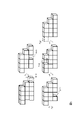
- Fig. 6 shows one step of the tunneling operation in units of 8 mass control objects.
- Two gaps are generated simultaneously from within Head, thereby moving two controlled objects within Head into position D.
- the two gaps generated at the Head are then sent to the Tail position and released from the controlled object structure from the Tail position.
- the two control objects in Tail move out of the Tail position (in FIG. 6, they move into the adjacent control object unit on the right).
- the position of the controlled object unit between Head and Tail is advanced by one.
- two voids may be included in multiple control object units sandwiched between Head and Tail. Under such conditions, disconnection does not occur in multiple controlled object units sandwiched between Head and Tail.
- the gap (void) generated in the Head is moved by sliding the two controlled objects that are in contact with the traveling direction of the void at each point after generation in the opposite direction of the traveling direction of the void. do.
- the void reaches the same position as when it was generated in Head within the control object unit (Tail' in FIG. 6) one before Tail.
- the void is released from the tail by sliding the control object unit in the tail that is in contact with the void in the direction of Tail' ⁇ Tail in the direction of Tail ⁇ Tail'.
- the generation position of the first and second voids is two controls that are not in the ah direction and have two different XYZ coordinate positions among the four control objects that are not in contact with D in Head. Target object.
- the 3rd and 4th void generation positions are the 2 control objects that are not in the 1st and 2nd void generation positions among the 4 control objects that are not in contact with D in Head.
- the 5th and 6th void generation positions are 2 of the 4 controlled objects that are not in contact with D in Head and are not in the ah direction. Assume that two controlled objects are located at different positions. Otherwise, the 5th and 6th void generation positions are two of the four controlled objects in contact with D in Head, two of which are not in the ah direction and have two different XYZ coordinate positions. Control object.
- the 7th and 8th void generation positions are at the 5th and 6th void generation positions among the four controlled objects that do not touch D in Head. Assume that there are two controlled objects that do not exist. Otherwise, the 7th and 8th void generation positions are the 2 control objects that are not in the 5th and 6th void generation positions among the 4 control objects that are in contact with D in Head. .
- the table in FIG. 13 shows.
- the void generation position number conforms to FIG.
- 1 is the positive direction of the X axis
- 2 is the positive direction of the Y axis
- 3 is the negative direction of the X axis
- 4 is the negative direction of the Y axis
- 5 is the positive direction of the Z axis
- 6 is the negative direction of the Z axis. do.
- voids are generated at positions 2 and 4 of the control object unit following the control object unit of Head.
- the region S ⁇ G of the intersection of the set S of initial positions and the set G of target positions is composed of C mutually disconnected regions A S ⁇ G1 , A S ⁇ G2 , A S ⁇ G3 , ..., A S ⁇ GC Suppose that it is configured by C is an integer of 1 or more.
- the selection of the top control object unit Head should ensure that none of these C objects become disconnected from the control object structure during the deformation operation. is. For example, if the control object units in S are gradually moved into G, the number of control object units remaining in S will decrease accordingly. If we are not careful in this process, it can happen that there is no control object in S or G that can be used for deformation while keeping the common part from being disconnected from the control object structure. In order to avoid such a situation, the following technique is adopted in substantially the same manner as in Non-Patent Document 2.
- Tail be the control object unit with the largest Manhattan distance in S from Ei among the control object units within a certain A SS ⁇ Gj .
- This Tail selection processing is assumed to be (3-3). The processing of (3-3) is performed by the tail control object unit selection unit 5, which will be described later.
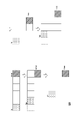
- FIG. 7(1) shows the initial position S for each controlled object.
- FIG. 7(2) shows the target position G for each controlled object.
- the disconnected S ⁇ G regions are A S ⁇ G1 indicated by light dots and A S ⁇ G2 indicated by dark dots.
- a S ⁇ G1 is chosen as A S ⁇ Gstart .
- the position of A S ⁇ G1 is added to Up.
- the regions of SS ⁇ G divided by Up are A SS ⁇ G1 indicated by a thick dashed line and A SS ⁇ G2 indicated by a thick one-dot chain line.
- the regions of GS ⁇ G divided by Up are AGS ⁇ G1 indicated by a thick dashed line and AGS ⁇ G2 indicated by a thick dashed line.
- E1 is chosen as the position in Up bordering AGS ⁇ G1 and E2 is chosen as the position in Up bordering AGS ⁇ G2 .
- E1 is the entrance to A GS ⁇ G1
- E2 can be said to be the entrance to A GS ⁇ G2 .
- control object unit selected as Head is indicated by a thick line
- D is indicated by a dashed line
- control object unit selected as Tail is indicated by a thick dashed line.
- selecting Head, Tail, and D results in the formation of FIG. will move to
- a S ⁇ G1 Up.
- D is added to Up.
- one of D and A S ⁇ G2 is added to Up.
- the last one of A SS ⁇ G1 is Tail, and the last gap of A GS ⁇ G1 is D.
- one of A SS ⁇ G2 becomes Tail, and all A S ⁇ G2 are filled (the gap of A S ⁇ G2 that is filled here becomes a new A GS ⁇ G2 , and the old AGS ⁇ G2 in Fig. 7 becomes AGS ⁇ G3 ).
- the last one of A S ⁇ G2 becomes Tail, and the old A GS ⁇ G2 in Fig. 7 is filled.
- Non-Patent Document 2 What differs from the conventional method (Non-Patent Document 2) is the handling of Ei set in (2) of [Head_Tail_Selection].
- any position in Up that touched the gap in G could be selected as Head, but here, D can be set in the same A GS ⁇ Gj as much as possible. I try to choose Head. This is because in the linearization of the platoon deformation motion described later, it is better to select Heads so that D can be set continuously within the same A GS ⁇ Gi , from the start of tanning motion performed by a set of Head and Tail, This is because it is possible to shorten the time until the start of the tunneling operation of the next pair of Head and Tail.
- the Manhattan distance from Ei at the position selected as Head next will be either ⁇ Ei or ⁇ Ei +1.
- the position of Head is often the previous Head or D position.
- the time interval in such a case is the minimum possible. is close to the value of
- step t When each HeadTail is selected (step t), the calculation of "the time from the start of the tunneling operation performed by a head and tail pair to the start of the tunneling operation of the next head and tail pair" is performed, for example, as follows. . Note that the processing of [Time_Interval] described below is performed by the operation plan determination unit 6 .
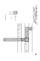
- the first void that left Head t is indicated by the thick line.
- the void generation start time difference between Head t and Head t-1 is set so as to pass through the indicated ⁇ .
- the series of control object units (tannering snake) from Head t to Tail t are indicated by dots, and the series of control object units (tannering snake) from Head t-1 to Tail t-1 are hatched. is indicated.
- the horizontal stripes indicate where the motion paths of these tunneling snakes overlap.
- Wt is the number of operation steps required to complete the generation of all voids from one controlled object unit.
- the waiting time for each tunneling operation in each HeadTail is shortened without colliding each void.
- control device includes a set selection unit 1, an entrance position selection unit 2, a head control object unit selection unit 3, a destination position selection unit 4, a tail control object unit selection unit 5, and an operation plan determination unit. 6, a set adding unit 7, a control unit 8 and a moving unit 9, for example.
- control method is implemented, for example, by having each component of the control device perform the processing from step S1 to step S9 shown in FIG. 11 and described below.
- the set selection unit 1 performs the process (1) of [Head_Tail_Selection].
- the set selection unit 1 selects one partial common position area A S ⁇ Select Gstart as set Up (step S1).
- the entrance position selection unit 2 performs the process (2) of [Head_Tail_Selection].
- J is a predetermined positive integer
- I is a predetermined positive integer
- the head control object unit selection unit 3 performs the processing of (3-1) of [Head_Tail_Selection].
- the head control object unit selection unit 3 selects a control object at a position that belongs to the set Up and is adjacent to a position where no control object unit exists in the partial target position area A GS ⁇ Gi .
- the one having the smallest Manhattan distance in the partial target position area AGS ⁇ Gi from the entrance position Ei is selected as the head control object unit Head (step S3).
- Information about the selected head control object unit Head is output to the target position selection unit 4 and the motion plan determination unit 6 .
- the target position selection unit 4 performs the processing of (3-2) of [Head_Tail_Selection].
- the target position selection unit 4 selects a position that is in contact with the leading control object unit Head and where no control object unit exists within the partial target position area A GS ⁇ Gi as the target position D, Add to the set Up (step S4).
- Information about the selected target position D is output to the motion plan determination unit 6 .
- Information about the set Up updated by the addition is output to the set addition unit 7 .
- the tail control target unit selection unit 5 performs the processing of (3-3) of [Head_Tail_Selection].
- the tail control object unit selection unit 5 selects the control object unit having the largest Manhattan distance in the partial initial position area A SS ⁇ Gj from the entrance position Ei among the control object units in the partial initial position area A SS ⁇ Gj . It is selected as the tail control object unit Tail (step S5).
- Tail Information about the selected tail control object unit Tail is output to the motion plan determination unit 6 .
- the operation plan determination unit 6 performs the processes (3) to (5) of [Tunneling_Linear].
- the operation plan determination unit 6 selects a series of control objects from the head control object unit Head selected by the head control object unit selection unit to the tail control object unit Tail selected by the tail control object unit selection unit.
- a motion plan is determined for moving the object unit so that the leading controlled object unit Head moves to the target position D and follows the motion of the leading controlled object unit (step S6).
- the action plan determination unit 6 decides the action plan so that at least one of the following conditions (i) and (ii) is satisfied.
- a series of controlled object units should be arranged so that the voids for moving the series of controlled object units do not overlap with the voids for moving the series of controlled object units that move one time earlier. A latency for unit movement is determined.
- the motion plan satisfies the condition (i)
- the number of voids generated at the same time is doubled compared to the conventional method, so the speed of the tunneling motion can be increased accordingly.
- the tumbling motion determined one hour ago and the tumbling motion determined at the current time can be performed in parallel.
- the motion plan satisfies at least one of the conditions (i) and (ii)
- the time required for platoon transformation can be shortened compared to the conventional method.
- the set addition unit 7 performs the processing of (4) of [Head_Tail_Selection].
- the set adding unit 7 connects the control object unit within the target position G. All the positions of the control object unit at the current position are added to the set Up (step S7).
- the repetition control unit 8 performs the processing of (6) of [Tunneling_Linear].
- the repetition control unit 8 performs the processing of the head control object unit selection unit 3, the target position selection unit 4, the tail control object unit selection unit 5, and the operation plan determination unit 6 according to the operation plan for each control object. Repeat until all can move to the target position (step S8).
- the finally generated motion plan is output to the moving unit 9.
- the moving unit 9 performs the process of (7) of [Tunneling_Linear].
- the moving unit 9 moves the control object unit according to the determined operation plan (step S9).
- control device may be performed directly or may be performed via a storage unit (not shown).
- a program that describes this process can be recorded on a computer-readable recording medium.
- a computer-readable recording medium is, for example, a non-temporary recording medium, specifically a magnetic recording device, an optical disc, or the like.
- this program will be carried out, for example, by selling, transferring, lending, etc. portable recording media such as DVDs and CD-ROMs on which the program is recorded.
- the program may be distributed by storing the program in the storage device of the server computer and transferring the program from the server computer to other computers via the network.
- a computer that executes such a program for example, first stores a program recorded on a portable recording medium or a program transferred from a server computer once in the auxiliary recording unit 1050, which is its own non-temporary storage device. Store. When executing the process, this computer reads the program stored in the auxiliary recording section 1050, which is its own non-temporary storage device, into the storage section 1020, and executes the process according to the read program. As another execution form of this program, the computer may read the program directly from the portable recording medium into the storage unit 1020 and execute processing according to the program. It is also possible to execute processing in accordance with the received program each time the is transferred.
- ASP Application Service Provider
- the above-mentioned processing is executed by a so-called ASP (Application Service Provider) type service, which does not transfer the program from the server computer to this computer, and realizes the processing function only by its execution instruction and result acquisition.
- ASP Application Service Provider
- the program in this embodiment includes information that is used for processing by a computer and that conforms to the program (data that is not a direct instruction to the computer but has the property of prescribing the processing of the computer, etc.).
- the device is configured by executing a predetermined program on a computer, but at least part of these processing contents may be implemented by hardware.
Landscapes
- Engineering & Computer Science (AREA)
- Aviation & Aerospace Engineering (AREA)
- Radar, Positioning & Navigation (AREA)
- Remote Sensing (AREA)
- Physics & Mathematics (AREA)
- General Physics & Mathematics (AREA)
- Automation & Control Theory (AREA)
- Control Of Position, Course, Altitude, Or Attitude Of Moving Bodies (AREA)
Abstract
制御装置は、集合選択部1、入口位置選択部2、先頭制御対象物単位選択部3、目的位置選択部4、尾部制御対象物単位選択部5、動作計画決定部6、集合追加部7、制御部8及び移動部9を例えば備えている。動作計画決定部6が決定する動作計画では、(i)一連の制御対象物単位を構成する制御対象物の位置の中でボイドを発生させる2個の位置を決定し、決定した2個の位置及び決定した2個の位置に隣接する先頭方向にある一連の制御対象物を先頭方向に移動させる処理が繰り返し行われ、又は、(ii)動作計画では、一連の制御対象物単位を移動させるためのボイドが、一時刻前に移動する一連の制御対象物単位を移動させるためのボイドが重ならないように、一連の制御対象物単位の移動の待ち時間が決定される。
Description
本発明は、複数の制御対象物の行動を制御する技術に関する。
近年、多数の自律移動ロボットを効率的に制御にするための研究が活発に行われている。その任務内容は、人の入れない箇所の監視、物品の搬送などさまざまであるが、多数のロボットの協調動作による隊列形成を効率的に行わせるための技術が求められており盛んに研究が行われている。
特に、ロボットの隊列制御の中でも、ロボット同士が互いに接したままの状態で、アメーバのように全体で移動を行うという仮定の下でのロボット隊列制御においては、ロボット同士の相対的な位置関係から、各ロボットの絶対位置の決定が可能であるという利点と、付加的な位置計測用の装備を必要としないという利点があり、そのようなロボットの研究もおこなわれている。例えば、非特許文献1に示す研究に至る一連の研究では、ある隊列から他の隊列に変化する隊列制御が示されている(例えば、非特許文献1参照。)。
このような、多数のロボットによる効率的な隊列形成を実現するには、それぞれのロボットの配置、動作順序などを事前に計画することが重要である。このような計画においては、当然ながら、複数のロボットが動作する実環境における障害物の存在や経路の形状なども十分に考慮しなければならない。
非特許文献1に示す研究に示されている手法では、複数の立方体形状のロボット同士での伸長収縮面動作(あるロボットが、他のロボットと接した状態で、伸び縮みしつつ移動する動作)によるロボットの隊列変形が扱われている。
非特許文献2及び特許文献1では、各ロボットが接した状態での動作を想定している。各ロボットは同一(ホモジニアス)であるとし、目標形態内部での各ロボットの目標位置が定まってない場合の隊列制御を実現している。複数の立方体形状のロボット同士での面せん断動作(あるロボットが、他のロボットと接した状態で、接する面上をスライド移動する動作)によるロボットの隊列変形が扱われている。ロボットが初期状態でとる隊列位置の集合とロボットの目標位置の集合の共通部分内に非接続箇所がある場合でも適用可能である。
S. Vassilvitskii, M. Yim, J. Suh, "A Complete, Local and Parallel Reconfiguration Algorithm for Cube Style Modular Robots", in Proc.2002 IEEE Int. Conf. Robotics and Automation, pp. 117-122, Washington DC, May, 2002.
H. Kawano, "Distributed Tunneling Reconfiguration of Sliding Cubic Modular Robots in Severe Space Requirements", in Proc.14th Int. Symposium on Distributed Autonomous Robotic Systems, paper no. 1, Boulder, CO, Oct., 2018.
非特許文献2及び特許文献1では、隊列変形に要する時間が長い可能性があった。
本発明は、従来よりも短い時間で隊列変更をすることができる制御装置、方法及びプログラムを提供することである。
この発明の一態様による制御装置は、所定の初期位置Sにある複数の制御対象物単位を所定の目標位置Gに移動させる制御装置であって、各制御対象物単位には複数の制御対象物が含まれているとし、各制御対象物単位が他の制御対象物単位と隣接することにより制御対象物単位が一塊の制御対象物構造を形成していることを制御対象物構造の接続性と言うとし、初期位置Sと目標位置Gの共通部分を共通位置とし、共通位置は互いに非接続な複数の部分共通位置領域から構成されているとして、ある1つの部分共通位置領域を集合Upとして選択する集合選択部と、I,Jは所定の正の整数であり、初期位置Sから共通位置S∩Gを除いた領域S-S∩Gは集合Upによって分断された少なくとも1つの部分初期位置領域AS-S∩Gj(j=1,…,J)で構成されており、目標位置Gから共通位置S∩Gを除いた領域G-S∩Gは集合Upによって分断された少なくとも1つの部分目標位置領域AG-S∩Gi(i=1,…,I)で構成されており、少なくとも1つの部分目標位置領域AG-S∩Gi(i=1,…,I)のそれぞれに接する集合Up内の位置を入口位置Ei(i=1,…,I)として選択する入口位置選択部と、集合Upに属する位置にあり、部分目標位置領域AG-S∩Giの中の制御対象物単位が存在していない位置に隣接する位置にある制御対象物単位のうち入口位置Eiからの部分目標位置領域AG-S∩Giでのマンハッタン距離が最も小さいものを先頭制御対象物単位Headとして選択する先頭制御対象物単位選択部と、先頭制御対象物単位Headに接する位置であって、部分目標位置領域AG-S∩Gi内の制御対象物単位が存在していない位置を目的位置Dとして選択し、集合Upに追加する目的位置選択部と、部分初期位置領域AS-S∩Gj内の制御対象物単位のうち入口位置Eiからの部分初期位置領域AS-S∩Gjでのマンハッタン距離が最も大きいものを尾部制御対象物単位Tailとして選択する尾部制御対象物単位選択部と、先頭制御対象物単位選択部で選択された先頭制御対象物単位Headから尾部制御対象物単位選択部で選択された尾部制御対象物単位Tailまでの一連の制御対象物単位を、先頭制御対象物単位Headが目的位置Dに移動し、先頭の制御対象物単位の動作を追従するように移動するための動作計画を決定する動作計画決定部と、動作計画では、一連の制御対象物単位を構成する制御対象物の位置の中でボイドを発生させる2個の位置を決定し、決定した2個の位置及び決定した2個の位置に隣接する先頭方向にある一連の制御対象物を先頭方向に移動させる処理が繰り返し行われ、集合Upが集合Upに含まれない部分共通位置領域内の位置にある制御対象物単位に接しているとき、その制御対象物単位から目標位置G内で接続している位置にある制御対象物単位の位置の全てを集合Upに追加する集合追加部と、先頭制御対象物単位選択部、目的位置選択部、尾部制御対象物単位選択部及び動作計画決定部の処理を、動作計画により、制御対象物単位の全てが目標位置に移動することができるようになるまで繰り返す繰り返し制御部と、決定された動作計画に従って、制御対象物単位を移動させる移動部と、を備えている。
この発明の一態様による制御装置は、所定の初期位置Sにある複数の制御対象物単位を所定の目標位置Gに移動させる制御装置であって、各制御対象物単位には複数の制御対象物が含まれているとし、各制御対象物単位が他の制御対象物単位と隣接することにより制御対象物単位が一塊の制御対象物構造を形成していることを制御対象物構造の接続性と言うとし、初期位置Sと目標位置Gの共通部分を共通位置とし、共通位置は互いに非接続な複数の部分共通位置領域から構成されているとして、ある1つの部分共通位置領域を集合Upとして選択する集合選択部と、I,Jは所定の正の整数であり、初期位置Sから共通位置S∩Gを除いた領域S-S∩Gは集合Upによって分断された少なくとも1つの部分初期位置領域AS-S∩Gj(j=1,…,J)で構成されており、目標位置Gから共通位置S∩Gを除いた領域G-S∩Gは集合Upによって分断された少なくとも1つの部分目標位置領域AG-S∩Gi(i=1,…,I)で構成されており、少なくとも1つの部分目標位置領域AG-S∩Gi(i=1,…,I)のそれぞれに接する集合Up内の位置を入口位置Ei(i=1,…,I)として選択する入口位置選択部と、集合Upに属する位置にあり、部分目標位置領域AG-S∩Giの中の制御対象物単位が存在していない位置に隣接する位置にある制御対象物単位のうち入口位置Eiからの部分目標位置領域AG-S∩Giでのマンハッタン距離が最も小さいものを先頭制御対象物単位Headとして選択する先頭制御対象物単位選択部と、先頭制御対象物単位Headに接する位置であって、部分目標位置領域AG-S∩Gi内の制御対象物単位が存在していない位置を目的位置Dとして選択し、集合Upに追加する目的位置選択部と、部分初期位置領域AS-S∩Gj内の制御対象物単位のうち入口位置Eiからの部分初期位置領域AS-S∩Gjでのマンハッタン距離が最も大きいものを尾部制御対象物単位Tailとして選択する尾部制御対象物単位選択部と、先頭制御対象物単位選択部で選択された先頭制御対象物単位Headから尾部制御対象物単位選択部で選択された尾部制御対象物単位Tailまでの一連の制御対象物単位を、先頭制御対象物単位Headが目的位置Dに移動し、先頭の制御対象物単位の動作を追従するように移動するための動作計画を決定する動作計画決定部と、動作計画では、一連の制御対象物単位を移動させるためのボイドが、一時刻前に移動する一連の制御対象物単位を移動させるためのボイドが重ならないように、一連の制御対象物単位の移動の待ち時間が決定され、集合Upが集合Upに含まれない部分共通位置領域内の位置にある制御対象物単位に接しているとき、その制御対象物単位から目標位置G内で接続している位置にある制御対象物単位の位置の全てを集合Upに追加する集合追加部と、先頭制御対象物単位選択部、目的位置選択部、尾部制御対象物単位選択部及び動作計画決定部の処理を、動作計画により、制御対象物単位の全てが目標位置に移動することができるようになるまで繰り返す繰り返し制御部と、決定された動作計画に従って、制御対象物単位を移動させる移動部と、を備えている。
制御対象物を移動させるためのボイドを2個発生させることで、又は、一連の制御対象物単位を移動させるためのボイドが一時刻前に移動する一連の制御対象物単位を移動させるためのボイドが重ならないように一連の制御対象物単位の移動の待ち時間を決定することで、従来よりも短い時間で隊列変更をすることができる。
以下、本発明の実施形態について説明する。なお、以下の説明に用いる図面では、同じ機能を持つ構成部や同じ処理を行うステップには同一の符号を記し、重複説明を省略する。
<理論的背景>
まず、制御装置及び方法の理論的背景について説明する。以下、行動制御の対象である制御対象物が、ロボットである場合を例に挙げて説明するが、制御対象物は、制御の対象となり得るものであれば、ロボット以外であってもよい。
まず、制御装置及び方法の理論的背景について説明する。以下、行動制御の対象である制御対象物が、ロボットである場合を例に挙げて説明するが、制御対象物は、制御の対象となり得るものであれば、ロボット以外であってもよい。
[問題設定]
多数の制御対象物が協調して、各制御対象物が接した状態を維持しつつ移動を行い、初期位置における隊列形成状態から目標位置への隊列変形を行う任務は、例えば図1に例示するような、互いに接する面同士をスライドさせて移動していくことが可能な立方体型の制御対象物の使用を想定する。図2に示すように、壁で区切られた部屋(ただし図中、壁を省略する)においての初期位置から目標位置まで複数の制御対象物の移動によって実現するものである。
多数の制御対象物が協調して、各制御対象物が接した状態を維持しつつ移動を行い、初期位置における隊列形成状態から目標位置への隊列変形を行う任務は、例えば図1に例示するような、互いに接する面同士をスライドさせて移動していくことが可能な立方体型の制御対象物の使用を想定する。図2に示すように、壁で区切られた部屋(ただし図中、壁を省略する)においての初期位置から目標位置まで複数の制御対象物の移動によって実現するものである。
制御対象物については、例えば図1に示すように、制御対象物の周囲縦横高さ方向(以下「上下左右前後方向」ともいう)6マスのうち1つに他の制御対象物が存在している状態を維持しながら移動をするものとする。この手法では1つの制御対象物自身が、一台の制御対象物のサイズ分の距離を移動することで、一回の動作の移動量を正確に測ることができるというメリットがある。また、1つの面を共有する隣り合う制御対象物との相対的な位置を計測しあうことで、制御対象物の群れ全体の中での各制御対象物の位置も容易に知ることができる。このため、制御対象物の移動量の誤差によって、隊列が崩れるといった問題を起こしにくい。また、複数の制御対象物を連結したように、同時に複数の制御対象物を移動させていくことが可能である。なお、制御対象物は、隣の位置に他の制御対象物が存在しているか否か、障害物があるか否か、そして、自身が目標位置上にいるかどうかを知ることができるものとする。
任務を行う制御対象物は、p台(p≧16=8×2)であり、各制御対象物は、隣接する制御対象物と一面以上を共有しつつ、三次元空間におけるX-Y-Z軸方向に移動可能とする。図1の各立方体は、それぞれの制御対象物の位置を示すものである。各立方体には制御対象物は一台しか存在することができない。それぞれの制御対象物は、移動しようとする方向に障害物か他の制御対象物がある場合には、静止をするものと仮定する。なお、制御対象物が存在しうる立方体状の空間をマス、または、格子ともいう。図2において、濃い灰色のマスは制御対象物が存在する位置を示す。図2Aの制御対象物が存在する位置は制御対象物の初期位置の集合を示し、図2Cの制御対象物が存在する位置は制御対象物の目標位置の集合を示す。図2Bに示すように、目標位置の集合と初期位置の集合は重なり合う部分を持っている。目標位置の集合で表される領域を目標隊列エリアともいう。このように、各初期位置及び各目標位置は、それぞれ縦横高さ方向の少なくとも何れかの方向において他の初期位置及び目標位置と隣接し、制御対象物の初期位置及び目標位置での隊列形状はそれぞれ一塊の任意の形状である。
[制御対象物の座標設定]
それぞれの制御対象物i(iは制御対象物番号を表すi=0,1,2,3,…,p-1)の位置を(Xr[i],Yr[i],Zr[i])とし、初期位置を(Xr0[i],Yr0[i],Zr0[i])とし、目標位置を(Xre[i],Yre[i],Zre[i])とするとき、本問題は、初期位置に配置された制御対象物が、目標位置まで移動するための行動計画を求めることと定義できる。制御対象物の初期位置の集合をs、目標位置(Xre[i],Yre[i],Zre[i])の集合をgとする。
それぞれの制御対象物i(iは制御対象物番号を表すi=0,1,2,3,…,p-1)の位置を(Xr[i],Yr[i],Zr[i])とし、初期位置を(Xr0[i],Yr0[i],Zr0[i])とし、目標位置を(Xre[i],Yre[i],Zre[i])とするとき、本問題は、初期位置に配置された制御対象物が、目標位置まで移動するための行動計画を求めることと定義できる。制御対象物の初期位置の集合をs、目標位置(Xre[i],Yre[i],Zre[i])の集合をgとする。
[任務空間の定義]
iを制御対象物番号としたとき、制御対象物iの各状態(制御対象物の位置と行動)は離散値で表現される。部屋をX,Y,Zの直交座標系からなる3次元空間で表すと、X軸、Y軸、Z軸をそれぞれ離散化表現した値により各位置を表現する。つまり、部屋(3次元空間)は格子で区切られ、各格子が各位置に対応する。また、各格子において、障害物の「ある/なし」が予め設定されている。
iを制御対象物番号としたとき、制御対象物iの各状態(制御対象物の位置と行動)は離散値で表現される。部屋をX,Y,Zの直交座標系からなる3次元空間で表すと、X軸、Y軸、Z軸をそれぞれ離散化表現した値により各位置を表現する。つまり、部屋(3次元空間)は格子で区切られ、各格子が各位置に対応する。また、各格子において、障害物の「ある/なし」が予め設定されている。
[制御対象物動作の定義]
また、行動主体は部屋に配置されている各制御対象物となる。制御対象物i(iは制御対象物番号)の行動aは、静止、縦横高さ方向への1格子分の移動、の計7種類のうちのいずれかを取る。例えば、a∈{0,1,2,3,4,5,6}として、
0: 静止
1: 三次元空間内でX軸正方向に1格子だけ移動する
2: 三次元空間内でY軸正方向に1格子だけ移動する
3: 三次元空間内でX軸負方向に1格子だけ移動する
4: 三次元空間内でY軸負方向に1格子だけ移動する
5: 三次元空間内でZ軸正方向に1格子だけ移動する
6: 三次元空間内でZ軸負方向に1格子だけ移動する
とする。
また、行動主体は部屋に配置されている各制御対象物となる。制御対象物i(iは制御対象物番号)の行動aは、静止、縦横高さ方向への1格子分の移動、の計7種類のうちのいずれかを取る。例えば、a∈{0,1,2,3,4,5,6}として、
0: 静止
1: 三次元空間内でX軸正方向に1格子だけ移動する
2: 三次元空間内でY軸正方向に1格子だけ移動する
3: 三次元空間内でX軸負方向に1格子だけ移動する
4: 三次元空間内でY軸負方向に1格子だけ移動する
5: 三次元空間内でZ軸正方向に1格子だけ移動する
6: 三次元空間内でZ軸負方向に1格子だけ移動する
とする。
[探索計算上の問題点]
このような任務環境における状態空間は、制御対象物数×3の次元数の状態を持ち、かつ選択可能な行動数は、制御対象物の行動(=7通り)の制御対象物数乗だけ存在する。例えば、制御対象物数が50で、部屋の縦横高さ方向の格子数がそれぞれ20であるとすれば状態数は20の150乗個にもなり、探索計算に要する資源の量は膨大なものとなる。さらに制御対象物数が1台増えるごとに、その状態数は8000倍増加していくことになる。本実施形態の[問題設定]の項で説明したように、制御対象物同士が接しているという拘束条件を取り入れる場合、制御対象物のお互いの移動を考慮したうえで探索計算行わなければならないために、根本的な計算量の削減は難しく、複数制御対象物を使用する場合の大きな問題となっている。
このような任務環境における状態空間は、制御対象物数×3の次元数の状態を持ち、かつ選択可能な行動数は、制御対象物の行動(=7通り)の制御対象物数乗だけ存在する。例えば、制御対象物数が50で、部屋の縦横高さ方向の格子数がそれぞれ20であるとすれば状態数は20の150乗個にもなり、探索計算に要する資源の量は膨大なものとなる。さらに制御対象物数が1台増えるごとに、その状態数は8000倍増加していくことになる。本実施形態の[問題設定]の項で説明したように、制御対象物同士が接しているという拘束条件を取り入れる場合、制御対象物のお互いの移動を考慮したうえで探索計算行わなければならないために、根本的な計算量の削減は難しく、複数制御対象物を使用する場合の大きな問題となっている。
[非特許文献2における特徴]
非特許文献2におけるホモジニアス隊列制御では、上述の計算負荷の問題を解決するための方策の1つとして、ボイド制御の考え方を導入している。また、[問題設定]で述べたような隊列変形の問題を克服するために8マス制御対象物単位の考え方も導入している。
非特許文献2におけるホモジニアス隊列制御では、上述の計算負荷の問題を解決するための方策の1つとして、ボイド制御の考え方を導入している。また、[問題設定]で述べたような隊列変形の問題を克服するために8マス制御対象物単位の考え方も導入している。
まず、ボイド制御について説明する。ここでいうボイドとは、ある制御対象物が別の位置に移動した後に、元いた位置にできる空隙のことである。別の言い方をすると、ボイドとは、制御対象物の移動する方向と反対の方向に移動する仮想的な存在である。こうした群制御対象物の隊列形成問題においては、複数の制御対象物の動作に着目するがゆえに、その探索計算量が爆発してしまうが、視点を変えて、ボイドの動きに着目すれば、多数の制御対象物の動作計画の問題を単一のボイドの動作計画として考えることができ、探索計算負荷の軽減に適している。しかし、変形動作中に制御対象物単位に属する各制御対象物はちりじりになって、それぞれ別の制御対象物単位内に分かれてしまい、その後の制御対象物入れ替え動作が必要な場合の負荷上昇にもつながってしまっていた。また、初期位置と目標位置が共通部分を持ち、かつ、それらの共通部分が複数の非接続部分に分かれている場合には適用不可能であった。
[8マス制御対象物単位の導入]
そこで、図4に示すように、8つの隣接した制御対象物を1つの単位とし(制御対象物単位)、制御対象物は、この制御対象物単位を維持しつつ移動を行うこととする。言い換えると、8台毎に1つの制御対象物単位を構成し、1つの制御対象物単位を構成する8台の制御対象物はそれぞれ3つの方向において1つの制御対象物単位を構成する他の制御対象物と隣接した状態を維持しつつ移動を行う。この制御対象物単位の集団は、互いに制御対象物単位ごとに一面を共有し、接しながら移動をするように制御される。すべての制御対象物は同一でホモジニアスであるとする。
そこで、図4に示すように、8つの隣接した制御対象物を1つの単位とし(制御対象物単位)、制御対象物は、この制御対象物単位を維持しつつ移動を行うこととする。言い換えると、8台毎に1つの制御対象物単位を構成し、1つの制御対象物単位を構成する8台の制御対象物はそれぞれ3つの方向において1つの制御対象物単位を構成する他の制御対象物と隣接した状態を維持しつつ移動を行う。この制御対象物単位の集団は、互いに制御対象物単位ごとに一面を共有し、接しながら移動をするように制御される。すべての制御対象物は同一でホモジニアスであるとする。
ここでは8台の制御対象物がなす制御対象物単位が1つのマスの単位(本実施形態では、以下、この単位を「マス単位」または「位置単位」ともいう)であるとし、1つのマス単位を一状態として状態空間を組む。制御対象物単位の位置を(Xr_u[j],Yr_u[j], Zr_u[j])(j=0,1,2,…j_max-1)としたとき、その制御対象物単位j内の制御対象物をi0,i1,i2,i3,i4,i5,i6,i7とすれば、
Xr[i0] = 2 ×Xr_u[j]
Yr[i0] = 2 ×Yr_u[j] + 1
Zr[i0] = 2 ×Zr_u[j]
Xr[i1] = 2 ×Xr_u[j] + 1
Yr[i1] = 2 ×Yr_u[j] + 1
Zr[i1] = 2 ×Zr_u[j]
Xr[i2] = 2 ×Xr_u[j]
Yr[i2] = 2 ×Yr_u[j] + 1
Zr[i2] = 2 ×Zr_u[j] + 1
Xr[i3] = 2 ×Xr_u[j] + 1
Yr[i3] = 2 ×Yr_u[j] + 1
Zr[i3] = 2 ×Zr_u[j] + 1
Xr[i4] = 2 ×Xr_u[j]
Yr[i4] = 2 ×Yr_u[j]
Zr[i4] = 2 ×Zr_u[j]
Xr[i5] = 2 ×Xr_u[j] + 1
Yr[i5] = 2 ×Yr_u[j]
Zr[i5] = 2 ×Zr_u[j]
Xr[i6] = 2 ×Xr_u[j]
Yr[i6] = 2 ×Yr_u[j]
Zr[i6] = 2 ×Zr_u[j]+1
Xr[i7] = 2 ×Xr_u[j]+1(図4参照)
Yr[i7] = 2 ×Yr_u[j]
Zr[i7] = 2 ×Zr_u[j] + 1
なお、隊列変形中各時点で各制御対象物iが所属する制御対象物単位jを表す変数をRr[i]=jとする。また、制御対象物が前記i0,i1,i2,i3,i4,i5,i6,i7のどの位置にあるかを指す変数をIr[i]=(0,1,2,3,4,5,6,7)とする。各制御対象物単位の初期位置を(Xr_u0[j],Yr_u0[j],Zr_u0[j])とし、目標位置を(Xr_ue[j],Yr_ue[j],Zr_ue[j])とする。以下、制御対象物の全体数pを8の倍数とする。
Xr[i0] = 2 ×Xr_u[j]
Yr[i0] = 2 ×Yr_u[j] + 1
Zr[i0] = 2 ×Zr_u[j]
Xr[i1] = 2 ×Xr_u[j] + 1
Yr[i1] = 2 ×Yr_u[j] + 1
Zr[i1] = 2 ×Zr_u[j]
Xr[i2] = 2 ×Xr_u[j]
Yr[i2] = 2 ×Yr_u[j] + 1
Zr[i2] = 2 ×Zr_u[j] + 1
Xr[i3] = 2 ×Xr_u[j] + 1
Yr[i3] = 2 ×Yr_u[j] + 1
Zr[i3] = 2 ×Zr_u[j] + 1
Xr[i4] = 2 ×Xr_u[j]
Yr[i4] = 2 ×Yr_u[j]
Zr[i4] = 2 ×Zr_u[j]
Xr[i5] = 2 ×Xr_u[j] + 1
Yr[i5] = 2 ×Yr_u[j]
Zr[i5] = 2 ×Zr_u[j]
Xr[i6] = 2 ×Xr_u[j]
Yr[i6] = 2 ×Yr_u[j]
Zr[i6] = 2 ×Zr_u[j]+1
Xr[i7] = 2 ×Xr_u[j]+1(図4参照)
Yr[i7] = 2 ×Yr_u[j]
Zr[i7] = 2 ×Zr_u[j] + 1
なお、隊列変形中各時点で各制御対象物iが所属する制御対象物単位jを表す変数をRr[i]=jとする。また、制御対象物が前記i0,i1,i2,i3,i4,i5,i6,i7のどの位置にあるかを指す変数をIr[i]=(0,1,2,3,4,5,6,7)とする。各制御対象物単位の初期位置を(Xr_u0[j],Yr_u0[j],Zr_u0[j])とし、目標位置を(Xr_ue[j],Yr_ue[j],Zr_ue[j])とする。以下、制御対象物の全体数pを8の倍数とする。
また、図4の例に限らず、制御対象物単位は以下の条件を満たすよう構成されていればよい。すなわち、制御対象物単位は、(1)三次元の直交座標系で各軸方向に長さM(M≧2、ただし、制御対象物1個の長さを長さ1とする)を有する立方体形状の空間(以降この空間をメタモジュールとする。)をなす構造であり、(2)各軸方向にM個の制御対象物が隣接する構造を含む。例えば、図4に例示する制御対象物単位は、(1)各軸方向の長さM=2とした計8マスの立方体からなるメタモジュール構造であり、(2)各軸方向において2個の制御対象物が隣接する構造が含まれている。
以後の説明では、制御対象物単位の一例として、図4に示す8個の制御対象物からなる構造を制御対象物単位とする場合について説明するが、例えば、M3個分の大きさのメタモジュール内で上述の(1)(2)の条件を満たすよう構成された制御対象物単位であれば同様の効果を得ることができる。
[ホモジニアス隊列制御]
各制御対象物単位jが初期位置の集合S内にて、任意の位置に存在する状態から、各制御対象物単位jをそれぞれ目標位置の集合のうちのいずれかの位置(Xr_ue[j],Yr_ue[j],Zr_ue[j])に配置させるホモジニアス制御対象物隊列制御の方法について以下説明していく。
各制御対象物単位jが初期位置の集合S内にて、任意の位置に存在する状態から、各制御対象物単位jをそれぞれ目標位置の集合のうちのいずれかの位置(Xr_ue[j],Yr_ue[j],Zr_ue[j])に配置させるホモジニアス制御対象物隊列制御の方法について以下説明していく。
ここで、集合S、Gは、8マスの制御対象物単位で構成されているものとする。
図5に示す通り、集合Sの状態にある制御対象物構造を集合Gの状態に変形させるには、タネリングと呼ばれる方法をとる。図5に示す動作においては、先頭の制御対象物単位Headと尾部の制御対象物単位Tailを結ぶ一連の制御対象物単位がいわば蛇のような形で、先頭制御対象物単位Headの動作を追従する方式で動作する。なお、他のタネリングを行う制御対象物単位、例えば非特許文献2に示すような伸長収縮制御対象物単位を使用した2×2×2の制御対象物単位を使用した制御対象物構造においてもこのタネリング動作は同様であり、本発明で示すタネリングのHeadとTailの選択方法は、同様に適用可能である。タネリングを使用した隊列変形は障害物のある環境においても、隊列変形動作を初期位置の集合と目標位置の集合以外の位置を使用せずに実行可能である。
図6に、8マス制御対象物単位のタネリング動作の1ステップを示す。Head内から同時に2つの空隙が生成され、それにより、Head内の2つの制御対象物が、D位置内に移動する。Headで生成された2つの空隙はその後、Tail位置まで送られて、Tail位置より制御対象物構造から放出される。その過程で、Tail内の2つの制御対象物が、Tail位置の外に出る(図6中、右隣の制御対象物単位内に移動する。)。図6の一連の動作により、HeadとTailの間の制御対象物単位が1つだけ位置を進める。このプロセス中、HeadとTailに挟まれる複数の制御対象物単位内に2つのボイドが含まれる場合が発生するが、ボイドを含む制御対象物単位同士が接する位置関係になることはなく、このような条件でHeadとTailに挟まれる複数の制御対象物単位において、非接続が生じることはない。
この過程にて、Headにて生成された空隙(ボイド)は、生成後にボイドの各時点での進行方向に接する2つの制御対象物を、ボイドの進行方向の逆方向にスライドさせることで移動をする。この移動方法を繰り返すことにより、ボイドはTailの1つ手前の制御対象物単位内(図6中Tail’)にて、Headで生成された時と同じ位置にたどり着く。この後、Tail’→Tailの方向にボイドと接する位置にあるTail内の制御対象物単位を、Tail→Tail’の方向にスライドさせることで、ボイドはTailから放出される。ここで注意しなければならないのは、Head内にてボイドを生成する際に、その生成位置を適切に選択しなければ、Headでのボイド生成時、およびTailからのボイド放出時に、制御対象物の非接続が生じてしまうことである。本発明においては、Headにて一度に一つのボイドしか生成しない非特許文献2の場合と異なり、Headにて一度に2つのボイドを生成するので、これについては特に注意を要する。これらを考慮したHeadでのボイド生成位置に関する条件は以下の通りである。以下Head→Dの方向をah, Tail→Tail’の方向をatとする。なお、以下に説明する[Void_Generation_Rule]の処理は、動作計画決定部6により行われる。
[Void_Generation_Rule]
(1)1個目2個目のボイドの生成位置は、Head内Dに接しない4つの制御対象物のうち、ah方向ではない2つのXYZ座標位置が2つとも異なる位置にある2つの制御対象物とする。
(1)1個目2個目のボイドの生成位置は、Head内Dに接しない4つの制御対象物のうち、ah方向ではない2つのXYZ座標位置が2つとも異なる位置にある2つの制御対象物とする。
(2) 3個目4個目のボイドの生成位置は、Head内Dに接しない4つの制御対象物のうち、1個目2個目のボイド生成位置にない2つの制御対象物とする。
(3) ahとatが逆方向の時、5個目6個目のボイドの生成位置は、Head内Dに接しない4つの制御対象物のうち、ah方向ではない2つのXYZ座標位置が2つとも異なる位置にある2つの制御対象物とする。それ以外の時、5個目6個目のボイドの生成位置は、Head内Dに接する4つの制御対象物のうち、ah方向ではない2つのXYZ座標位置が2つとも異なる位置にある2つの制御対象物とする。
(4) ahとatが逆方向の時、7個目8個目のボイドの生成位置は、Head内Dに接しない4つの制御対象物のうち、5個目6個目のボイド生成位置にない2つの制御対象物とする。それ以外の時、7個目8個目のボイドの生成位置は、Head内Dに接する4つの制御対象物のうち、5個目6個目のボイド生成位置にない2つの制御対象物とする。
具体的には、例えば図13の表のとおりである。なお、ボイド発生位置番号は図4に準ずる。また、ah,atに関して、1はX軸正方向、2はY軸正方向、3はX軸負方向、4はY軸負方向、5はZ軸正方向、6はZ軸負方向を意味する。
図6では、Head→Dの方向はX軸正方向であるためah=1であり、Tail→Tail’の方向はX軸正方向であるためat=1である。このため、図6は、上記の表のah=1,at=1の場合に対応する。図6(2)ではHeadである制御対象物単位の6,0の位置にボイドが発生している。これが図13の表のah=1,at=1の場合の「1つ目」の6、「2つ目」の0に対応している。また、図6(4)ではHeadである制御対象物単位に続く制御対象物単位の2,4の位置にボイドが発生している。これが、図13の表のah=1,at=1の場合の「3つ目」の2、「4つ目」の4に対応している。また、図6(6)ではHeadである制御対象物単位の7,1の位置にボイドが発生している。これが図13の表のah=1,at=1の場合の「5つ目」の7、「6つ目」の1に対応している。図6(8)ではHeadである制御対象物単位に続く制御対象物単位の3,5の位置にボイドが発生している。これが、図13の表のah=1,at=1の場合の「7つ目」の3、「8つ目」の5に対応している。
つづいて、先頭制御対象物単位Headと尾部制御対象物単位Tailの選び方について述べる。初期位置の集合Sと目的位置の集合Gの共通部分の領域S∩Gは、互いに非接続なC個の領域AS∩G1, AS∩G2, AS∩G3, …, AS∩GCにより構成されているとする。Cは、1以上の整数である。
まず先頭制御対象物単位Headの選択について注意すべきことは、変形動作中に全体の制御対象物構造からこれらのC個のうちのいずれも、制御対象物構造から非接続にならないようにすることである。例えば、S内の制御対象物単位を徐々にG内に移動させたとするとその分S内に残る制御対象物単位数は少なくなる。この過程で注意を怠ると、共通部分が制御対象物構造から非接続とならないようにしつつも変形のために使用できる制御対象物がS内にもG内にも存在しないという事態が起こりうる。そのような事態を避けるために、非特許文献2とほぼ同様に、以下の手法を採用する。
[Head_Tail_Selection]
(1) 変形過程開始前に、複数の非接続なS∩G領域をAS∩G1、AS∩G2、AS∩G3、AS∩G4、、、とし、それらの1つを選択してAS∩Gstartとする。AS∩Gstart内の制御対象物単位位置をすべて集合Upのメンバーとする。この処理は、後述する集合選択部1により行われる。
(1) 変形過程開始前に、複数の非接続なS∩G領域をAS∩G1、AS∩G2、AS∩G3、AS∩G4、、、とし、それらの1つを選択してAS∩Gstartとする。AS∩Gstart内の制御対象物単位位置をすべて集合Upのメンバーとする。この処理は、後述する集合選択部1により行われる。
(2) Up初期化時、および(4)でのUp更新時に、Upによって分断されたS-S∩Gの領域をAS-S∩G1、AS-S∩G2、AS-S∩G3、AS-S∩G4、、、とし、Upによって分断されたG-S∩Gの領域をAG-S∩G1、AG-S∩G2、AG-S∩G3、AG-S∩G4、、、とする。AG-S∩G1、AG-S∩G2、AG-S∩G3、AG-S∩G4、、、に接するUp内の位置をひとつずつ選び、Eiとする。この処理は、後述する入口位置選択部2により行われる。i=1、j=1とする。
(3) 各ステップでのHeadとTailの選択:AG-S∩Gi内の位置がすべて制御対象物で埋まっているならば、iをインクリメントする。Up内にあり、かつまだ制御対象物で埋められていないAG-S∩Gi内の位置に接している制御対象物のうちEiからのAG-S∩Gi内でのマンハッタン距離が最も近いものをHeadとする。このHeadの選択の処理を(3-1)とする。この(3-1)の処理は、後述する先頭制御対象物単位選択部3により行われる。
Headに接するまだ制御対象物で埋められていないAG-S∩Gi内の位置を1つ選びDとする。DをUpに追加する。このDをUpに追加する処理を(3-2)とする。この(3-2)の処理は、後述する目的位置選択部4により行われる。
AS-S∩Gj内にもう制御対象物単位がない場合は、jをインクリメントする。あるAS-S∩Gj内にある制御対象物単位のうち、EiからのS内マンハッタン距離が最も大きい制御対象物単位をTailとする。このTailの選択の処理を(3-3)とする。この(3-3)の処理は、後述する尾部制御対象物単位選択部5により行われる。
(4) UpがAS∩Gstart以外のUpに含まれないAS∩G1、AS∩G2、AS∩G3、AS∩G4、、、内の位置にある制御対象物単位に接しているとき、その制御対象物単位からG内で接続している位置にある制御対象物単位位置をすべてUpに追加する。このUpへの追加の処理は、後述する集合追加部7により行われる。
図7及び図8を用いて、制御対象物単位の初期位置Sから目標位置Gへの移動の例を説明する。図7(1)は、制御対象物単位の初期位置Sを示している。図7(2)は、制御対象物単位の目標位置Gを示している。
図7(1)(2)において、非接続なS∩G領域は、薄いドットで示されたAS∩G1と、濃いドットで示されたAS∩G2とである。この例では、AS∩Gstartとして、AS∩G1が選択される。AS∩G1の位置がUpに追加される。
図7(1)において、Upによって分断されたS-S∩Gの領域は、太い破線で示されたAS-S∩G1と、太い一点鎖線で示されたAS-S∩G2とである。
図7(2)において、Upによって分断されたG-S∩Gの領域は、太い破線で示されたAG-S∩G1と、太い一点鎖線で示されたAG-S∩G2である。この例では、AG-S∩G1に接するUp内の位置としてE1が選択され、AG-S∩G2に接するUp内の位置としてE2が選択されている。E1は、AG-S∩G1への入口であり、E2はAG-S∩G2への入口とも言える。
図8(1)から図8(8)において、Headとして選択された制御対象物単位を太線で示し、Dを破線で示す、Tailとして選択された制御対象物単位を太い一点鎖線で示す。i=1,…,8として、図8(i)で選択されたHeadからTailまでの一連の制御対象物単位(タネリングスネイク)を、HeadがDに移動し、他の一連の制御対象物単位がHeadの動作を追従するように移動させると、図8(i+1)の隊列になる。この例では、図8(1)から図8(8)のように、Head,Tail,Dを選択すると、最終的に図8(9)の隊列となり、全ての制御対象物単位が目標位置Gに移動することになる。
なお、図8(1)において、先に述べたように、AS∩G1=Upとされる。図8(1)から図8(4)において、DがUpに追加される。図8(5)において、DとAS∩G2の1つがUpに追加される。図8(6)において、AS-S∩G1の最後の1つがTailになり、AG-S∩G1の最後の空隙がDとなる。図8(7)において、AS-S∩G2の1つがTailになり、AS∩G2が全部埋まる(ここで埋められるAS∩G2の空隙は、(5)のUp更新にて新たなAG-S∩G2となり、図7の旧AG-S∩G2は、AG-S∩G3となる。)。(8)にて、AS∩G2の最後の1つがTailになり、図7の旧AG-S∩G2が埋まる。
従来の手法(非特許文献2)と異なるのは、[Head_Tail_Selection]の(2)にて設定されているEiの扱いである。従来ではHeadの選択の際、Up内のどの位置からでもG内の空隙に接する位置であればHeadとして選択できたが、ここでは、できる限り同じAG-S∩Gj内にDを設定できるようにHeadを選ぶようにしている。これは、後述の隊列変形動作の線形化において、同じAG-S∩Gi内に連続してDを設定できるようにHeadを選んで行くほうが、あるHeadとTailの組で行うタネリング動作の開始から、次のHeadとTailの組のタネリング動作の開始までの時間を短くすることが可能だからである。例えば、ある時点でEiからのマンハッタン距離がδEiであるAG-S∩Gi位置をHeadとした場合、次にHeadとして選択される位置のEiからのマンハッタン距離はδEiかδEi+1となり、新しいHeadの位置は1つ前のHeadかDの位置である場合が多い。後述する「あるHeadとTailの組で行うタネリング動作の開始から、次のHeadとTailの組のタネリング動作の開始までの時間」を計算する式において、このような場合の時間間隔は取りうる最小の値に近い値になる。
従来手法では図6に示すタネリング動作が各HeadTailごとに終了してから、次のタネリングHeadTailでのタネリング動作を開始していたので、各HeadTailでのタネリング動作ごとに待ち時間が長く、そのため隊列変形に要する時間が長かった。そこで、あるHeadとTailの組で行うタネリング動作が終了する前に、次のHeadとTailの組のタネリング動作を開始することで、各HeadTailでのタネリング動作ごとの待ち時間を短縮する。
各HeadTail選択時(tステップ目)における「あるHeadとTailの組で行うタネリング動作の開始から、次のHeadとTailの組のタネリング動作の開始までの時間」の算出は例えば以下のように行う。なお、以下に説明する[Time_Interval]の処理は、動作計画決定部6により行われる。
[Time_Interval]
(1) tステップ目のHeadとTailを結ぶEiを経由する制御対象物構造内の経路をP[t][l](l=0,1,2,,,nt)、t-1ステップ目のHeadとTailを結ぶEiを経由する制御対象物構造内の経路をP[t-1][l](l=0,1,2,,,nt-1)とする。これらの経路はHeadから発生したボイドがTailに至るまでたどる経路である。P[t][0]、P[t-1][0]にHead位置が格納され、 P[t][nt]、P[t-1][nt-1]にTail位置が格納される。
(2) l←0とする。tl←1とする。Delay_buf←0とする。
(1) tステップ目のHeadとTailを結ぶEiを経由する制御対象物構造内の経路をP[t][l](l=0,1,2,,,nt)、t-1ステップ目のHeadとTailを結ぶEiを経由する制御対象物構造内の経路をP[t-1][l](l=0,1,2,,,nt-1)とする。これらの経路はHeadから発生したボイドがTailに至るまでたどる経路である。P[t][0]、P[t-1][0]にHead位置が格納され、 P[t][nt]、P[t-1][nt-1]にTail位置が格納される。
(2) l←0とする。tl←1とする。Delay_buf←0とする。
(3) Interval_Cand[tl] ←0とする。P[t][l]の位置と同じ位置がP[t-tl][m](m=0,1,2,,,nt-1)内にあるか探索する。ない場合、lをインクリメントし(3)を繰り返す。あった場合(4)へ
(4) P[t][l]=P[t-tl][m]のとき、その時のl、mをlc, mcとする。すべてのmc値に対して小さい値のものから順に以下の計算をし、計算が済んだ後Delay_buf += Interval_Cand[tl]。そのあとでl=ntでないならlをインクリメントして(3)へ、l=ntでt-tl=0なら(5)へ、l=ntでt-tl≠0ならl←0としてtlをインクリメントし(3)へ
Wt←7.
If( mc = 0 ){
If( Interval_Cand[tl] < Wt + 2 - lc - Delay_buf ){
Interval_Cand[tl] ← Wt + 2 - lc - Delay_buf;
}
}
Else{
If( Interval_Cand[tl] < Wt + 1 + mc - lc - Delay_buf ){
Interval_Cand[tl] ← Wt + 1 + mc - lc - Delay_buf;
}
}
(5) Interval_Cand[tl](tl=1~t)の値の中で最も大きいものをt-1ステップ目とtステップ目のタネリングの開始時刻の時間差Interval[t]とする。
(4) P[t][l]=P[t-tl][m]のとき、その時のl、mをlc, mcとする。すべてのmc値に対して小さい値のものから順に以下の計算をし、計算が済んだ後Delay_buf += Interval_Cand[tl]。そのあとでl=ntでないならlをインクリメントして(3)へ、l=ntでt-tl=0なら(5)へ、l=ntでt-tl≠0ならl←0としてtlをインクリメントし(3)へ
Wt←7.
If( mc = 0 ){
If( Interval_Cand[tl] < Wt + 2 - lc - Delay_buf ){
Interval_Cand[tl] ← Wt + 2 - lc - Delay_buf;
}
}
Else{
If( Interval_Cand[tl] < Wt + 1 + mc - lc - Delay_buf ){
Interval_Cand[tl] ← Wt + 1 + mc - lc - Delay_buf;
}
}
(5) Interval_Cand[tl](tl=1~t)の値の中で最も大きいものをt-1ステップ目とtステップ目のタネリングの開始時刻の時間差Interval[t]とする。
以上の処理は、tステップ目のHeadからTailに至るボイドの経路が、以前に実行されたタネリング動作で発生したボイドの動作経路に重なる場合には、先に発生したボイドがその新旧経路同士が重なる位置を通り過ぎるのを待つのに必要な待ち時間を計算している。
言い換えれば、以上の処理により、図9に例示するように、Head t-1を出発した8つ目のボイドが太線で示した□を通過した直後にHead tを出発した最初のボイドが太線で示した□を通過するようにHead tと、Head t-1のボイド生成開始時間差が設定される。なお、図9において、Head tからTail tの一連の制御対象物単位(タネリングスネイク)はドットで、Head t-1からTail t-1の一連の制御対象物単位(タネリングスネイク)は斜線で示されている。横ストライプで示されているのは、これらのタネリングスネイクの動作経路が重なる位置である。
Wtは1つの制御対象物単位からすべてのボイドの生成が終了するのに要する動作ステップ数である。図6において、斜線で示すHeadである制御対象物単位からボイドの生成が始まるのは図6(2)のときであり、すべてのボイドの生成が終了するのは図6(8)のときである。このため、ボイドが同時に2個発生する図6の例では、Wt=7となる。なお、同時に発生するボイドの数が1である場合には、Wt=15となる。
このような処理を行うことで、各ボイドが衝突することなく、各HeadTailでのタネリング動作ごとの待ち時間が短縮される。
以上に述べたタネリング手法をまとめると以下のようなプロセスになる。
[Tunneling_Linear]
(1) [Head_Tail_Selection]の(1)(2)を実行する。t=0とする。なお、[Tunneling_Linear]の(1)から(6)までの処理は仮想制御対象物によるシミュレーションで実行される。
(1) [Head_Tail_Selection]の(1)(2)を実行する。t=0とする。なお、[Tunneling_Linear]の(1)から(6)までの処理は仮想制御対象物によるシミュレーションで実行される。
[Tunneling_Linear]の(1)の処理は、後述するステップS1及びステップS2の処理に対応している。
(2) [Head_Tail_Selection]の(3)を実行する。
[Tunneling_Linear]の(2)の処理は、後述するステップS3からステップS5の処理に対応している。
(3) t>0の時[Time_Interval]を実行する。[Tunneling_Linear]の(3)から(5)の処理は、後述するステップS6の処理に対応している。
(4) tn=0とする。
(5) tn=2×tv(tv=0,1,2,3)のとき、2×tv+1番目と2×tv+2番目のボイドを[Void_Generation_Rule]に従って生成させる(例えば、図6参照。)。すでに生成済みのボイドについては、tn=nt - 1以外のとき、P[st][tn]→P[st][tn+1]の方向にボイドに接する2つの制御対象物をボイドの進行方向の逆方向にスライドさせることで、ボイドを移動させる(図6)。tn=nt - 1のとき、P[st][tn]→P[st][tn+1]の方向にボイドに接するTail内の制御対象物をボイドの進行方向の逆方向にスライドさせることで、ボイドを放出する(図6)。tステップ目の時刻tnで移動をした制御対象物の動作のみをhistory[t][i][tn]に記録する。(i=tステップ目で動作をした制御対象物すべて。tn=0,1,2、、、nt)。8つのボイドがすべて放出されてないならば、tnをインクリメントする。放出されたならば(6)へ。
(6) [Head_Tail_Selection]の(4)を実行して、Upに新たな位置が追加されたならば[Head_Tail_Selection]の(2)を実行する。まだG内に空隙があるならば、tをインクリメントし[Head_Tail_Selection]の(2)に戻る。
[Tunneling_Linear]の(6)の処理は、後述する繰り返し制御部8によるステップS8の処理に対応している。
(7) history[t][i][tn]に記録されたtステップ目のタネリングにおける制御対象物単位の動作をt-1ステップ目のタネリング開始からInterval[t]時刻ステップ後に開始することを全tにおいて実行する。
[Tunneling_Linear]の(7)の処理は、後述する移動部9によるステップS9に対応している。
[制御装置及び方法]
制御装置は、図10に示すように、集合選択部1、入口位置選択部2、先頭制御対象物単位選択部3、目的位置選択部4、尾部制御対象物単位選択部5、動作計画決定部6、集合追加部7、制御部8及び移動部9を例えば備えている。
制御装置は、図10に示すように、集合選択部1、入口位置選択部2、先頭制御対象物単位選択部3、目的位置選択部4、尾部制御対象物単位選択部5、動作計画決定部6、集合追加部7、制御部8及び移動部9を例えば備えている。
制御方法は、制御装置の各構成部が、以下に説明する及び図11に示すステップS1からステップS9の処理を行うことにより例えば実現される。
以下、制御装置の各構成部について説明する。
<集合選択部1>
集合選択部1は、[Head_Tail_Selection]の(1)の処理を行う。
集合選択部1は、[Head_Tail_Selection]の(1)の処理を行う。
すなわち、集合選択部1は、複数の部分共通位置領域AS∩G1、AS∩G2、AS∩G3、AS∩G4、、、の中から、ある1つの部分共通位置領域AS∩Gstartを集合Upとして選択する(ステップS1)。
選択された集合Upについての情報は、入口位置選択部2に出力される。
<入口位置選択部2>
入口位置選択部2は、[Head_Tail_Selection]の(2)の処理を行う。
入口位置選択部2は、[Head_Tail_Selection]の(2)の処理を行う。
すなわち、入口位置選択部2は、少なくとも1つの部分目標位置領域AG-S∩Gi(i=1,…,I)のそれぞれに接する集合Up内の位置を入口位置Ei(i=1,…,I)として選択する(ステップS2)。
選択された入口位置Ei(i=1,…,I)についての情報は、先頭制御対象物単位選択部3に出力される。
ここで、Jは所定の正の整数として、初期位置Sから共通位置S∩Gを除いた領域S-S∩Gは前記集合Upによって分断された少なくとも1つの部分初期位置領域AS-S∩Gj(j=1,…,J)で構成されているとする。
また、Iは所定の正の整数として、目標位置Gから共通位置S∩Gを除いた領域G-S∩Gは集合Upによって分断された少なくとも1つの部分目標位置領域AG-S∩Gi(i=1,…,I)で構成されているとする。
<先頭制御対象物単位選択部3>
先頭制御対象物単位選択部3は、[Head_Tail_Selection]の(3-1)の処理を行う。
先頭制御対象物単位選択部3は、[Head_Tail_Selection]の(3-1)の処理を行う。
すなわち、先頭制御対象物単位選択部3は、集合Upに属する位置にあり、部分目標位置領域AG-S∩Giの中の制御対象物単位が存在していない位置に隣接する位置にある制御対象物単位のうち入口位置Eiからの部分目標位置領域AG-S∩Giでのマンハッタン距離が最も小さいものを先頭制御対象物単位Headとして選択する(ステップS3)。
選択された先頭制御対象物単位Headについての情報は、目的位置選択部4、動作計画決定部6に出力される。
<目的位置選択部4>
目的位置選択部4は、[Head_Tail_Selection]の(3-2)の処理を行う。
目的位置選択部4は、[Head_Tail_Selection]の(3-2)の処理を行う。
すなわち、目的位置選択部4は、先頭制御対象物単位Headに接する位置であって、部分目標位置領域AG-S∩Gi内の制御対象物単位が存在していない位置を目的位置Dとして選択し、集合Upに追加する(ステップS4)。
選択された目的位置Dについての情報は、動作計画決定部6に出力される。追加により更新された集合Upについての情報は、集合追加部7に出力される。
<尾部制御対象物単位選択部5>
尾部制御対象物単位選択部5は、[Head_Tail_Selection]の(3-3)の処理を行う。
尾部制御対象物単位選択部5は、[Head_Tail_Selection]の(3-3)の処理を行う。
すなわち、尾部制御対象物単位選択部5は、部分初期位置領域AS-S∩Gj内の制御対象物単位のうち入口位置Eiからの部分初期位置領域AS-S∩Gjでのマンハッタン距離が最も大きいものを尾部制御対象物単位Tailとして選択する(ステップS5)。
選択された尾部制御対象物単位Tailについての情報は、動作計画決定部6に出力される。
<動作計画決定部6>
動作計画決定部6は、[Tunneling_Linear]の(3)から(5)の処理を行う。
動作計画決定部6は、[Tunneling_Linear]の(3)から(5)の処理を行う。
すなわち、動作計画決定部6は、先頭制御対象物単位選択部で選択された先頭制御対象物単位Headから尾部制御対象物単位選択部で選択された尾部制御対象物単位Tailまでの一連の制御対象物単位を、先頭制御対象物単位Headが目的位置Dに移動し、先頭の制御対象物単位の動作を追従するように移動するための動作計画を決定する(ステップS6)。
動作計画決定部6は、以下の(i)(ii)の少なくとも一方の条件が満たされるように、動作計画を決定する。
(i)動作計画では、一連の制御対象物単位を構成する制御対象物の位置の中でボイドを発生させる2個の位置を決定し、決定した2個の位置及び決定した2個の位置に隣接する先頭方向にある一連の制御対象物を先頭方向に移動させる処理が繰り返し行われる。
(ii)動作計画では、一連の制御対象物単位を移動させるためのボイドが、一時刻前に移動する一連の制御対象物単位を移動させるためのボイドと重ならないように、一連の制御対象物単位の移動の待ち時間が決定される。
動作計画が(i)の条件を満たす場合には、従来と比較して、同時に発生するボイドの数が2倍になるため、その分タネリングの動作を高速化することができる。
動作計画が(ii)の条件を満たす場合には、一時刻前に決定されたタネリング動作と、現時刻に決定されたタネリング動作とを並列して行うことができる。
このため、動作計画が(i)(ii)の少なくとも一方の条件を満たす場合には、従来よりも隊列変形に要する時間を短くすることができる。
<集合追加部7>
集合追加部7は、[Head_Tail_Selection]の(4)の処理を行う。
集合追加部7は、[Head_Tail_Selection]の(4)の処理を行う。
すなわち、集合追加部7は、集合Upが集合Upに含まれない部分共通位置領域内の位置にある制御対象物単位に接しているとき、その制御対象物単位から目標位置G内で接続している位置にある制御対象物単位の位置の全てを集合Upに追加する(ステップS7)。
追加により更新された集合Upについての情報は、先頭制御対象物単位選択部3に出力される。
<繰り返し制御部8>
繰り返し制御部8は、[Tunneling_Linear]の(6)の処理を行う。
繰り返し制御部8は、[Tunneling_Linear]の(6)の処理を行う。
すなわち、繰り返し制御部8は、先頭制御対象物単位選択部3、目的位置選択部4、尾部制御対象物単位選択部5及び動作計画決定部6の処理を、動作計画により、制御対象物単位の全てが目標位置に移動することができるようになるまで繰り返す(ステップS8)。
最終的に生成された動作計画は、移動部9に出力される。
<移動部9>
移動部9は、[Tunneling_Linear]の(7)の処理を行う。
移動部9は、[Tunneling_Linear]の(7)の処理を行う。
移動部9は、決定された動作計画に従って、制御対象物単位を移動させる(ステップS9)。
[変形例]
以上、本発明の実施の形態について説明したが、具体的な構成は、これらの実施の形態に限られるものではなく、本発明の趣旨を逸脱しない範囲で適宜設計の変更等があっても、本発明に含まれることはいうまでもない。
以上、本発明の実施の形態について説明したが、具体的な構成は、これらの実施の形態に限られるものではなく、本発明の趣旨を逸脱しない範囲で適宜設計の変更等があっても、本発明に含まれることはいうまでもない。
実施の形態において説明した各種の処理は、記載の順に従って時系列に実行されるのみならず、処理を実行する装置の処理能力あるいは必要に応じて並列的にあるいは個別に実行されてもよい。
例えば、制御装置の構成部間のデータのやり取りは直接行われてもよいし、図示していない記憶部を介して行われてもよい。
[プログラム、記録媒体]
上述した各装置の各部の処理をコンピュータにより実現してもよく、この場合は各装置が有すべき機能の処理内容はプログラムによって記述される。そして、このプログラムを図12に示すコンピュータ1000の記憶部1020に読み込ませ、演算処理部1010、入力部1030、出力部1040などに動作させることにより、前記各装置における各種の処理機能がコンピュータ上で実現される。
上述した各装置の各部の処理をコンピュータにより実現してもよく、この場合は各装置が有すべき機能の処理内容はプログラムによって記述される。そして、このプログラムを図12に示すコンピュータ1000の記憶部1020に読み込ませ、演算処理部1010、入力部1030、出力部1040などに動作させることにより、前記各装置における各種の処理機能がコンピュータ上で実現される。
この処理内容を記述したプログラムは、コンピュータで読み取り可能な記録媒体に記録しておくことができる。コンピュータで読み取り可能な記録媒体は、例えば、非一時的な記録媒体であり、具体的には、磁気記録装置、光ディスク、等である。
また、このプログラムの流通は、例えば、そのプログラムを記録したDVD、CD-ROM等の可搬型記録媒体を販売、譲渡、貸与等することによって行う。さらに、このプログラムをサーバコンピュータの記憶装置に格納しておき、ネットワークを介して、サーバコンピュータから他のコンピュータにそのプログラムを転送することにより、このプログラムを流通させる構成としてもよい。
このようなプログラムを実行するコンピュータは、例えば、まず、可搬型記録媒体に記録されたプログラムもしくはサーバコンピュータから転送されたプログラムを、一旦、自己の非一時的な記憶装置である補助記録部1050に格納する。そして、処理の実行時、このコンピュータは、自己の非一時的な記憶装置である補助記録部1050に格納されたプログラムを記憶部1020に読み込み、読み込んだプログラムに従った処理を実行する。また、このプログラムの別の実行形態として、コンピュータが可搬型記録媒体から直接プログラムを記憶部1020に読み込み、そのプログラムに従った処理を実行することとしてもよく、さらに、このコンピュータにサーバコンピュータからプログラムが転送されるたびに、逐次、受け取ったプログラムに従った処理を実行することとしてもよい。また、サーバコンピュータから、このコンピュータへのプログラムの転送は行わず、その実行指示と結果取得のみによって処理機能を実現する、いわゆるASP(Application Service Provider)型のサービスによって、上述の処理を実行する構成としてもよい。なお、本形態におけるプログラムには、電子計算機による処理の用に供する情報であってプログラムに準ずるもの(コンピュータに対する直接の指令ではないがコンピュータの処理を規定する性質を有するデータ等)を含むものとする。
また、この形態では、コンピュータ上で所定のプログラムを実行させることにより、本装置を構成することとしたが、これらの処理内容の少なくとも一部をハードウェア的に実現することとしてもよい。
その他、この発明の趣旨を逸脱しない範囲で適宜変更が可能であることはいうまでもない。
Claims (6)
- 所定の初期位置Sにある複数の制御対象物単位を所定の目標位置Gに移動させる制御装置であって、
各前記制御対象物単位には複数の制御対象物が含まれているとし、各制御対象物単位が他の制御対象物単位と隣接することにより前記制御対象物単位が一塊の制御対象物構造を形成していることを制御対象物構造の接続性と言うとし、前記初期位置Sと前記目標位置Gの共通部分を共通位置とし、前記共通位置は互いに非接続な複数の部分共通位置領域から構成されているとして、
ある1つの部分共通位置領域を集合Upとして選択する集合選択部と、
I,Jは所定の正の整数であり、前記初期位置Sから前記共通位置S∩Gを除いた領域S-S∩Gは前記集合Upによって分断された少なくとも1つの部分初期位置領域AS-S∩Gj(j=1,…,J)で構成されており、前記目標位置Gから前記共通位置S∩Gを除いた領域G-S∩Gは前記集合Upによって分断された少なくとも1つの部分目標位置領域AG-S∩Gi(i=1,…,I)で構成されており、前記少なくとも1つの部分目標位置領域AG-S∩Gi(i=1,…,I)のそれぞれに接する前記集合Up内の位置を入口位置Ei(i=1,…,I)として選択する入口位置選択部と、
前記集合Upに属する位置にあり、前記部分目標位置領域AG-S∩Giの中の制御対象物単位が存在していない位置に隣接する位置にある制御対象物単位のうち前記入口位置Eiからの前記部分目標位置領域AG-S∩Giでのマンハッタン距離が最も小さいものを先頭制御対象物単位Headとして選択する先頭制御対象物単位選択部と、
前記先頭制御対象物単位Headに接する位置であって、前記部分目標位置領域AG-S∩Gi内の制御対象物単位が存在していない位置を目的位置Dとして選択し、前記集合Upに追加する目的位置選択部と、
前記部分初期位置領域AS-S∩Gj内の制御対象物単位のうち前記入口位置Eiからの前記部分初期位置領域AS-S∩Gjでのマンハッタン距離が最も大きいものを尾部制御対象物単位Tailとして選択する尾部制御対象物単位選択部と、
前記先頭制御対象物単位選択部で選択された先頭制御対象物単位Headから前記尾部制御対象物単位選択部で選択された尾部制御対象物単位Tailまでの一連の制御対象物単位を、前記先頭制御対象物単位Headが前記目的位置Dに移動し、先頭の制御対象物単位の動作を追従するように移動するための動作計画を決定する動作計画決定部と、
前記動作計画では、前記一連の制御対象物単位を構成する制御対象物の位置の中でボイドを発生させる2個の位置を決定し、決定した2個の位置及び前記決定した2個の位置に隣接する先頭方向にある一連の制御対象物を先頭方向に移動させる処理が繰り返し行われ、
前記集合Upが前記集合Upに含まれない部分共通位置領域内の位置にある制御対象物単位に接しているとき、その制御対象物単位から前記目標位置G内で接続している位置にある制御対象物単位の位置の全てを前記集合Upに追加する集合追加部と、
前記先頭制御対象物単位選択部、前記目的位置選択部、前記尾部制御対象物単位選択部及び前記動作計画決定部の処理を、前記動作計画により、前記制御対象物単位の全てが前記目標位置に移動することができるようになるまで繰り返す繰り返し制御部と、
前記決定された動作計画に従って、前記制御対象物単位を移動させる移動部と、
を含む制御装置。 - 請求項1の制御装置であって、
前記動作計画では、前記一連の制御対象物単位を移動させるためのボイドが、一時刻前に移動する一連の制御対象物単位を移動させるためのボイドが重ならないように、前記一連の制御対象物単位の移動の待ち時間が更に決定される、
制御装置。 - 所定の初期位置Sにある複数の制御対象物単位を所定の目標位置Gに移動させる制御装置であって、
各前記制御対象物単位には複数の制御対象物が含まれているとし、各制御対象物単位が他の制御対象物単位と隣接することにより前記制御対象物単位が一塊の制御対象物構造を形成していることを制御対象物構造の接続性と言うとし、前記初期位置Sと前記目標位置Gの共通部分を共通位置とし、前記共通位置は互いに非接続な複数の部分共通位置領域から構成されているとして、
ある1つの部分共通位置領域を集合Upとして選択する集合選択部と、
I,Jは所定の正の整数であり、前記初期位置Sから前記共通位置S∩Gを除いた領域S-S∩Gは前記集合Upによって分断された少なくとも1つの部分初期位置領域AS-S∩Gj(j=1,…,J)で構成されており、前記目標位置Gから前記共通位置S∩Gを除いた領域G-S∩Gは前記集合Upによって分断された少なくとも1つの部分目標位置領域AG-S∩Gi(i=1,…,I)で構成されており、前記少なくとも1つの部分目標位置領域AG-S∩Gi(i=1,…,I)のそれぞれに接する前記集合Up内の位置を入口位置Ei(i=1,…,I)として選択する入口位置選択部と、
前記集合Upに属する位置にあり、前記部分目標位置領域AG-S∩Giの中の制御対象物単位が存在していない位置に隣接する位置にある制御対象物単位のうち前記入口位置Eiからの前記部分目標位置領域AG-S∩Giでのマンハッタン距離が最も小さいものを先頭制御対象物単位Headとして選択する先頭制御対象物単位選択部と、
前記先頭制御対象物単位Headに接する位置であって、前記部分目標位置領域AG-S∩Gi内の制御対象物単位が存在していない位置を目的位置Dとして選択し、前記集合Upに追加する目的位置選択部と、
前記部分初期位置領域AS-S∩Gj内の制御対象物単位のうち前記入口位置Eiからの前記部分初期位置領域AS-S∩Gjでのマンハッタン距離が最も大きいものを尾部制御対象物単位Tailとして選択する尾部制御対象物単位選択部と、
前記先頭制御対象物単位選択部で選択された先頭制御対象物単位Headから前記尾部制御対象物単位選択部で選択された尾部制御対象物単位Tailまでの一連の制御対象物単位を、前記先頭制御対象物単位Headが前記目的位置Dに移動し、先頭の制御対象物単位の動作を追従するように移動するための動作計画を決定する動作計画決定部と、
前記動作計画では、前記一連の制御対象物単位を移動させるためのボイドが、一時刻前に移動する一連の制御対象物単位を移動させるためのボイドと重ならないように、前記一連の制御対象物単位の移動の待ち時間が決定され、
前記集合Upが前記集合Upに含まれない部分共通位置領域内の位置にある制御対象物単位に接しているとき、その制御対象物単位から前記目標位置G内で接続している位置にある制御対象物単位の位置の全てを前記集合Upに追加する集合追加部と、
前記先頭制御対象物単位選択部、前記目的位置選択部、前記尾部制御対象物単位選択部及び前記動作計画決定部の処理を、前記動作計画により、前記制御対象物単位の全てが前記目標位置に移動することができるようになるまで繰り返す繰り返し制御部と、
前記決定された動作計画に従って、前記制御対象物単位を移動させる移動部と、
を含む制御装置。 - 所定の初期位置Sにある複数の制御対象物単位を所定の目標位置Gに移動させる制御方法であって、
各前記制御対象物単位には複数の制御対象物が含まれているとし、各制御対象物単位が他の制御対象物単位と隣接することにより前記制御対象物単位が一塊の制御対象物構造を形成していることを制御対象物構造の接続性と言うとし、前記初期位置Sと前記目標位置Gの共通部分を共通位置とし、前記共通位置は互いに非接続な複数の部分共通位置領域から構成されているとして、
集合選択部が、ある1つの部分共通位置領域を集合Upとして選択する集合選択ステップと、
入口位置選択部が、I,Jは所定の正の整数であり、前記初期位置Sから前記共通位置S∩Gを除いた領域S-S∩Gは前記集合Upによって分断された少なくとも1つの部分初期位置領域AS-S∩Gj(j=1,…,J)で構成されており、前記目標位置Gから前記共通位置S∩Gを除いた領域G-S∩Gは前記集合Upによって分断された少なくとも1つの部分目標位置領域AG-S∩Gi(i=1,…,I)で構成されており、前記少なくとも1つの部分目標位置領域AG-S∩Gi(i=1,…,I)のそれぞれに接する前記集合Up内の位置を入口位置Ei(i=1,…,I)として選択する入口位置選択ステップと、
先頭制御対象物単位選択部が、前記集合Upに属する位置にあり、前記部分目標位置領域AG-S∩Giの中の制御対象物単位が存在していない位置に隣接する位置にある制御対象物単位のうち前記入口位置Eiからの前記部分目標位置領域AG-S∩Giでのマンハッタン距離が最も小さいものを先頭制御対象物単位Headとして選択する先頭制御対象物単位選択ステップと、
目的位置選択部が、前記先頭制御対象物単位Headに接する位置であって、前記部分目標位置領域AG-S∩Gi内の制御対象物単位が存在していない位置を目的位置Dとして選択し、前記集合Upに追加する目的位置選択ステップと、
尾部制御対象物単位選択部が、前記部分初期位置領域AS-S∩Gj内の制御対象物単位のうち前記入口位置Eiからの前記部分初期位置領域AS-S∩Gjでのマンハッタン距離が最も大きいものを尾部制御対象物単位Tailとして選択する尾部制御対象物単位選択ステップと、
動作計画決定部が、前記先頭制御対象物単位選択部で選択された先頭制御対象物単位Headから前記尾部制御対象物単位選択部で選択された尾部制御対象物単位Tailまでの一連の制御対象物単位を、前記先頭制御対象物単位Headが前記目的位置Dに移動し、先頭の制御対象物単位の動作を追従するように移動するための動作計画を決定する動作計画決定ステップと、
前記動作計画では、前記一連の制御対象物単位を構成する制御対象物の位置の中でボイドを発生させる2個の位置を決定し、決定した2個の位置及び前記決定した2個の位置に隣接する先頭方向にある一連の制御対象物を先頭方向に移動させる処理が繰り返し行われ、
集合追加部が、前記集合Upが前記集合Upに含まれない部分共通位置領域内の位置にある制御対象物単位に接しているとき、その制御対象物単位から前記目標位置G内で接続している位置にある制御対象物単位の位置の全てを前記集合Upに追加する集合追加ステップと、
繰り返し制御部が、前記先頭制御対象物単位選択ステップ、前記目的位置選択ステップ、前記尾部制御対象物単位選択ステップ及び前記動作計画決定ステップの処理を、前記動作計画により、前記制御対象物単位の全てが前記目標位置に移動することができるようになるまで繰り返す繰り返し制御ステップと、
移動部が、前記決定された動作計画に従って、前記制御対象物単位を移動させる移動ステップと、
を含む制御方法。 - 所定の初期位置Sにある複数の制御対象物単位を所定の目標位置Gに移動させる制御方法であって、
各前記制御対象物単位には複数の制御対象物が含まれているとし、各制御対象物単位が他の制御対象物単位と隣接することにより前記制御対象物単位が一塊の制御対象物構造を形成していることを制御対象物構造の接続性と言うとし、前記初期位置Sと前記目標位置Gの共通部分を共通位置とし、前記共通位置は互いに非接続な複数の部分共通位置領域から構成されているとして、
集合選択部が、ある1つの部分共通位置領域を集合Upとして選択する集合選択ステップと、
入口位置選択部が、I,Jは所定の正の整数であり、前記初期位置Sから前記共通位置S∩Gを除いた領域S-S∩Gは前記集合Upによって分断された少なくとも1つの部分初期位置領域AS-S∩Gj(j=1,…,J)で構成されており、前記目標位置Gから前記共通位置S∩Gを除いた領域G-S∩Gは前記集合Upによって分断された少なくとも1つの部分目標位置領域AG-S∩Gi(i=1,…,I)で構成されており、前記少なくとも1つの部分目標位置領域AG-S∩Gi(i=1,…,I)のそれぞれに接する前記集合Up内の位置を入口位置Ei(i=1,…,I)として選択する入口位置選択ステップと、
先頭制御対象物単位選択部が、前記集合Upに属する位置にあり、前記部分目標位置領域AG-S∩Giの中の制御対象物単位が存在していない位置に隣接する位置にある制御対象物単位のうち前記入口位置Eiからの前記部分目標位置領域AG-S∩Giでのマンハッタン距離が最も小さいものを先頭制御対象物単位Headとして選択する先頭制御対象物単位選択ステップと、
目的位置選択部が、前記先頭制御対象物単位Headに接する位置であって、前記部分目標位置領域AG-S∩Gi内の制御対象物単位が存在していない位置を目的位置Dとして選択し、前記集合Upに追加する目的位置選択ステップと、
尾部制御対象物単位選択部が、前記部分初期位置領域AS-S∩Gj内の制御対象物単位のうち前記入口位置Eiからの前記部分初期位置領域AS-S∩Gjでのマンハッタン距離が最も大きいものを尾部制御対象物単位Tailとして選択する尾部制御対象物単位選択ステップと、
動作計画決定部が、前記先頭制御対象物単位選択部で選択された先頭制御対象物単位Headから前記尾部制御対象物単位選択部で選択された尾部制御対象物単位Tailまでの一連の制御対象物単位を、前記先頭制御対象物単位Headが前記目的位置Dに移動し、先頭の制御対象物単位の動作を追従するように移動するための動作計画を決定する動作計画決定ステップと、
前記動作計画では、前記一連の制御対象物単位を移動させるためのボイドが、一時刻前に移動する一連の制御対象物単位を移動させるためのボイドが重ならないように、前記一連の制御対象物単位の移動の待ち時間が決定され、
集合追加部が、前記集合Upが前記集合Upに含まれない部分共通位置領域内の位置にある制御対象物単位に接しているとき、その制御対象物単位から前記目標位置G内で接続している位置にある制御対象物単位の位置の全てを前記集合Upに追加する集合追加ステップと、
繰り返し制御部が、前記先頭制御対象物単位選択ステップ、前記目的位置選択ステップ、前記尾部制御対象物単位選択ステップ及び前記動作計画決定ステップの処理を、前記動作計画により、前記制御対象物単位の全てが前記目標位置に移動することができるようになるまで繰り返す繰り返し制御ステップと、
移動部が、前記決定された動作計画に従って、前記制御対象物単位を移動させる移動ステップと、
を含む制御方法。 - 請求項1から3の何れかの制御装置の各部としてコンピュータを機能させるためのプログラム。
Priority Applications (1)
| Application Number | Priority Date | Filing Date | Title |
|---|---|---|---|
| PCT/JP2021/017699 WO2022239063A1 (ja) | 2021-05-10 | 2021-05-10 | 制御装置、方法及びプログラム |
Applications Claiming Priority (1)
| Application Number | Priority Date | Filing Date | Title |
|---|---|---|---|
| PCT/JP2021/017699 WO2022239063A1 (ja) | 2021-05-10 | 2021-05-10 | 制御装置、方法及びプログラム |
Publications (1)
| Publication Number | Publication Date |
|---|---|
| WO2022239063A1 true WO2022239063A1 (ja) | 2022-11-17 |
Family
ID=84028494
Family Applications (1)
| Application Number | Title | Priority Date | Filing Date |
|---|---|---|---|
| PCT/JP2021/017699 Ceased WO2022239063A1 (ja) | 2021-05-10 | 2021-05-10 | 制御装置、方法及びプログラム |
Country Status (1)
| Country | Link |
|---|---|
| WO (1) | WO2022239063A1 (ja) |
Citations (2)
| Publication number | Priority date | Publication date | Assignee | Title |
|---|---|---|---|---|
| US20140274416A1 (en) * | 2013-03-15 | 2014-09-18 | A.Q.B. Venture Capital B.V. | Shape-shifting a configuration of reusable elements |
| JP2018010493A (ja) * | 2016-07-14 | 2018-01-18 | 日本電信電話株式会社 | 行動制御システム、行動制御方法、プログラム |
-
2021
- 2021-05-10 WO PCT/JP2021/017699 patent/WO2022239063A1/ja not_active Ceased
Patent Citations (2)
| Publication number | Priority date | Publication date | Assignee | Title |
|---|---|---|---|---|
| US20140274416A1 (en) * | 2013-03-15 | 2014-09-18 | A.Q.B. Venture Capital B.V. | Shape-shifting a configuration of reusable elements |
| JP2018010493A (ja) * | 2016-07-14 | 2018-01-18 | 日本電信電話株式会社 | 行動制御システム、行動制御方法、プログラム |
Similar Documents
| Publication | Publication Date | Title |
|---|---|---|
| Zacharia et al. | Task scheduling and motion planning for an industrial manipulator | |
| JP6879233B2 (ja) | 制御装置、方法及びプログラム | |
| JP6559591B2 (ja) | 行動制御システム、その方法及びプログラム | |
| JP7136365B2 (ja) | 移動ロボット、移動ロボットの制御方法及びプログラム | |
| Moussa et al. | Cluster-based distributed self-reconfiguration algorithm for modular robots | |
| Saputra et al. | A swarm optimization approach for solving workspace determination of parallel manipulators | |
| JP7480869B2 (ja) | 制御装置、ハミルトン閉路拡張装置、方法及びプログラム | |
| JP6685957B2 (ja) | 制御対象物位置入れ替え制御装置、制御対象物位置入れ替え制御方法、プログラム | |
| Odem et al. | A self-reconfiguration algorithm for sliding triangular modular robots | |
| WO2023276065A1 (ja) | 制御装置、方法及びプログラム | |
| US11774970B2 (en) | Control apparatus, method and program | |
| JP6633467B2 (ja) | 行動制御システム、行動制御方法、プログラム | |
| US11625050B2 (en) | Moving robot, moving robot control method and program therefor | |
| US20250224742A1 (en) | Control apparatus, method and program | |
| WO2023281625A1 (ja) | 制御装置、方法及びプログラム | |
| JP6939395B2 (ja) | 制御装置、方法及びプログラム | |
| JP7014101B2 (ja) | 移動ロボット、移動ロボットの制御方法及びプログラム | |
| WO2023281582A1 (ja) | 制御装置、方法及びプログラム | |
| JP6939396B2 (ja) | 隊列制御装置、隊列制御方法、およびプログラム | |
| JP6881352B2 (ja) | 制御装置、方法及びプログラム | |
| JP6946933B2 (ja) | 隊列制御装置、隊列制御方法、およびプログラム | |
| Li et al. | Research on Planar Path Planning of Mobile Robot Based on Cellular Automata | |
| Cheng et al. | Warehouse operation scheduling platform based on digital twin | |
| Zhou et al. | On-line collision avoidance system for two PTP command-based manipulators with distributed controller | |
| JP7226588B2 (ja) | 行動制御装置、その方法及びプログラム |
Legal Events
| Date | Code | Title | Description |
|---|---|---|---|
| 121 | Ep: the epo has been informed by wipo that ep was designated in this application |
Ref document number: 21941797 Country of ref document: EP Kind code of ref document: A1 |
|
| NENP | Non-entry into the national phase |
Ref country code: DE |
|
| 122 | Ep: pct application non-entry in european phase |
Ref document number: 21941797 Country of ref document: EP Kind code of ref document: A1 |
|
| NENP | Non-entry into the national phase |
Ref country code: JP |