WO2022230760A1 - ゲーティングカメラ、センシングシステム、車両用灯具 - Google Patents
ゲーティングカメラ、センシングシステム、車両用灯具 Download PDFInfo
- Publication number
- WO2022230760A1 WO2022230760A1 PCT/JP2022/018484 JP2022018484W WO2022230760A1 WO 2022230760 A1 WO2022230760 A1 WO 2022230760A1 JP 2022018484 W JP2022018484 W JP 2022018484W WO 2022230760 A1 WO2022230760 A1 WO 2022230760A1
- Authority
- WO
- WIPO (PCT)
- Prior art keywords
- gating camera
- image
- ranges
- range
- gating
- Prior art date
- Legal status (The legal status is an assumption and is not a legal conclusion. Google has not performed a legal analysis and makes no representation as to the accuracy of the status listed.)
- Ceased
Links
Images











Classifications
-
- G—PHYSICS
- G01—MEASURING; TESTING
- G01S—RADIO DIRECTION-FINDING; RADIO NAVIGATION; DETERMINING DISTANCE OR VELOCITY BY USE OF RADIO WAVES; LOCATING OR PRESENCE-DETECTING BY USE OF THE REFLECTION OR RERADIATION OF RADIO WAVES; ANALOGOUS ARRANGEMENTS USING OTHER WAVES
- G01S7/00—Details of systems according to groups G01S13/00, G01S15/00, G01S17/00
- G01S7/48—Details of systems according to groups G01S13/00, G01S15/00, G01S17/00 of systems according to group G01S17/00
- G01S7/483—Details of pulse systems
- G01S7/484—Transmitters
-
- B—PERFORMING OPERATIONS; TRANSPORTING
- B60—VEHICLES IN GENERAL
- B60Q—ARRANGEMENT OF SIGNALLING OR LIGHTING DEVICES, THE MOUNTING OR SUPPORTING THEREOF OR CIRCUITS THEREFOR, FOR VEHICLES IN GENERAL
- B60Q1/00—Arrangement of optical signalling or lighting devices, the mounting or supporting thereof or circuits therefor
-
- B—PERFORMING OPERATIONS; TRANSPORTING
- B60—VEHICLES IN GENERAL
- B60Q—ARRANGEMENT OF SIGNALLING OR LIGHTING DEVICES, THE MOUNTING OR SUPPORTING THEREOF OR CIRCUITS THEREFOR, FOR VEHICLES IN GENERAL
- B60Q1/00—Arrangement of optical signalling or lighting devices, the mounting or supporting thereof or circuits therefor
- B60Q1/0017—Devices integrating an element dedicated to another function
- B60Q1/0023—Devices integrating an element dedicated to another function the element being a sensor, e.g. distance sensor, camera
-
- B—PERFORMING OPERATIONS; TRANSPORTING
- B60—VEHICLES IN GENERAL
- B60Q—ARRANGEMENT OF SIGNALLING OR LIGHTING DEVICES, THE MOUNTING OR SUPPORTING THEREOF OR CIRCUITS THEREFOR, FOR VEHICLES IN GENERAL
- B60Q1/00—Arrangement of optical signalling or lighting devices, the mounting or supporting thereof or circuits therefor
- B60Q1/02—Arrangement of optical signalling or lighting devices, the mounting or supporting thereof or circuits therefor the devices being primarily intended to illuminate the way ahead or to illuminate other areas of way or environments
- B60Q1/24—Arrangement of optical signalling or lighting devices, the mounting or supporting thereof or circuits therefor the devices being primarily intended to illuminate the way ahead or to illuminate other areas of way or environments for lighting other areas than only the way ahead
- B60Q1/249—Arrangement of optical signalling or lighting devices, the mounting or supporting thereof or circuits therefor the devices being primarily intended to illuminate the way ahead or to illuminate other areas of way or environments for lighting other areas than only the way ahead for illuminating the field of view of a sensor or camera
-
- G—PHYSICS
- G01—MEASURING; TESTING
- G01S—RADIO DIRECTION-FINDING; RADIO NAVIGATION; DETERMINING DISTANCE OR VELOCITY BY USE OF RADIO WAVES; LOCATING OR PRESENCE-DETECTING BY USE OF THE REFLECTION OR RERADIATION OF RADIO WAVES; ANALOGOUS ARRANGEMENTS USING OTHER WAVES
- G01S17/00—Systems using the reflection or reradiation of electromagnetic waves other than radio waves, e.g. lidar systems
- G01S17/02—Systems using the reflection of electromagnetic waves other than radio waves
- G01S17/06—Systems determining position data of a target
- G01S17/08—Systems determining position data of a target for measuring distance only
- G01S17/10—Systems determining position data of a target for measuring distance only using transmission of interrupted, pulse-modulated waves
-
- G—PHYSICS
- G01—MEASURING; TESTING
- G01S—RADIO DIRECTION-FINDING; RADIO NAVIGATION; DETERMINING DISTANCE OR VELOCITY BY USE OF RADIO WAVES; LOCATING OR PRESENCE-DETECTING BY USE OF THE REFLECTION OR RERADIATION OF RADIO WAVES; ANALOGOUS ARRANGEMENTS USING OTHER WAVES
- G01S17/00—Systems using the reflection or reradiation of electromagnetic waves other than radio waves, e.g. lidar systems
- G01S17/02—Systems using the reflection of electromagnetic waves other than radio waves
- G01S17/06—Systems determining position data of a target
- G01S17/08—Systems determining position data of a target for measuring distance only
- G01S17/10—Systems determining position data of a target for measuring distance only using transmission of interrupted, pulse-modulated waves
- G01S17/18—Systems determining position data of a target for measuring distance only using transmission of interrupted, pulse-modulated waves wherein range gates are used
-
- G—PHYSICS
- G01—MEASURING; TESTING
- G01S—RADIO DIRECTION-FINDING; RADIO NAVIGATION; DETERMINING DISTANCE OR VELOCITY BY USE OF RADIO WAVES; LOCATING OR PRESENCE-DETECTING BY USE OF THE REFLECTION OR RERADIATION OF RADIO WAVES; ANALOGOUS ARRANGEMENTS USING OTHER WAVES
- G01S17/00—Systems using the reflection or reradiation of electromagnetic waves other than radio waves, e.g. lidar systems
- G01S17/88—Lidar systems specially adapted for specific applications
- G01S17/89—Lidar systems specially adapted for specific applications for mapping or imaging
- G01S17/894—Three-dimensional [3D] imaging with simultaneous measurement of time-of-flight at a two-dimensional [2D] array of receiver pixels, e.g. time-of-flight cameras or flash lidar
-
- G—PHYSICS
- G01—MEASURING; TESTING
- G01S—RADIO DIRECTION-FINDING; RADIO NAVIGATION; DETERMINING DISTANCE OR VELOCITY BY USE OF RADIO WAVES; LOCATING OR PRESENCE-DETECTING BY USE OF THE REFLECTION OR RERADIATION OF RADIO WAVES; ANALOGOUS ARRANGEMENTS USING OTHER WAVES
- G01S17/00—Systems using the reflection or reradiation of electromagnetic waves other than radio waves, e.g. lidar systems
- G01S17/88—Lidar systems specially adapted for specific applications
- G01S17/93—Lidar systems specially adapted for specific applications for anti-collision purposes
- G01S17/931—Lidar systems specially adapted for specific applications for anti-collision purposes of land vehicles
-
- G—PHYSICS
- G01—MEASURING; TESTING
- G01S—RADIO DIRECTION-FINDING; RADIO NAVIGATION; DETERMINING DISTANCE OR VELOCITY BY USE OF RADIO WAVES; LOCATING OR PRESENCE-DETECTING BY USE OF THE REFLECTION OR RERADIATION OF RADIO WAVES; ANALOGOUS ARRANGEMENTS USING OTHER WAVES
- G01S7/00—Details of systems according to groups G01S13/00, G01S15/00, G01S17/00
- G01S7/48—Details of systems according to groups G01S13/00, G01S15/00, G01S17/00 of systems according to group G01S17/00
- G01S7/483—Details of pulse systems
- G01S7/486—Receivers
- G01S7/4868—Controlling received signal intensity or exposure of sensor
-
- G—PHYSICS
- G08—SIGNALLING
- G08G—TRAFFIC CONTROL SYSTEMS
- G08G1/00—Traffic control systems for road vehicles
- G08G1/16—Anti-collision systems
Definitions
- the present invention relates to gating cameras.
- An object identification system that senses the position and type of objects around the vehicle is used for automated driving and automatic control of headlamp light distribution.
- An object identification system includes a sensor and a processor that analyzes the output of the sensor. Sensors are selected from cameras, LiDAR (Light Detection and Ranging, Laser Imaging Detection and Ranging), millimeter-wave radar, ultrasonic sonar, etc., taking into consideration the application, required accuracy, and cost.
- LiDAR Light Detection and Ranging, Laser Imaging Detection and Ranging
- millimeter-wave radar ultrasonic sonar
- Depth information cannot be obtained from a general monocular camera. Therefore, it is difficult to separate multiple overlapping objects located at different distances.
- a TOF (Time Of Flight) camera is known as a camera that can obtain depth information.
- a TOF camera projects infrared light from a light-emitting device, measures the flight time until the reflected light returns to an image sensor, and obtains an image by converting the flight time into distance information.
- a gating camera divides an imaging range into a plurality of ranges, and performs imaging a plurality of times while changing exposure timing and exposure time for each range. This yields a slice image for each range of interest, each slice image containing only the objects contained in the corresponding range.
- the present disclosure has been made in such a situation, and one exemplary purpose of certain aspects thereof is to provide a gating camera capable of reducing the amount of data.
- a range image is used as the output format of the ToF camera.
- a distance image is an image whose pixel values are values obtained by converting flight time into distance information.
- a range image of a ToF camera shows that objects at the same distance have the same color regardless of their reflectance. Therefore, for example, when a sign is photographed, information such as characters and graphics written on the sign is lost from the distance image obtained by the ToF camera.
- the present disclosure has been made in such a situation, and one exemplary purpose of certain aspects thereof is to provide a sensor capable of generating range image data containing more information.
- the present disclosure has been made in such a situation, and one exemplary purpose of certain aspects thereof is to provide a gating camera capable of reducing power consumption.
- An aspect of the present disclosure relates to a gating camera that divides a field of view into multiple ranges in the depth direction and generates multiple slice images corresponding to the multiple ranges.
- the gating camera is capable of controlling light emission timing, and includes a lighting device that emits probe light, an image sensor that can control exposure timing, and light emission timing of the lighting device and imaging timing of the image sensor for each range. and a controller that controls the effective photographing range of the image sensor according to the vehicle speed.
- a gating camera includes an illumination device capable of controlling emission timing and irradiating probe light, an image sensor capable of controlling exposure timing, and N (N ⁇ 2) visual fields in the depth direction.
- a controller that controls the light emission timing of the lighting device and the imaging timing of the image sensor for each range, and the N slice images output by the image sensor corresponding to the N ranges are synthesized.
- an image processing device that generates an image.
- the N ranges are assigned N different colors C 1 to C N .
- Each pixel of the composite image has a pixel value that is a blend of the N colors C 1 -C N respectively by a factor based on the pixel values v 1 -v N of the corresponding pixels of the N slice images.
- Another aspect of the present disclosure relates to an image processing apparatus used with a gating camera that divides the field of view into N ranges in the depth direction and outputs N slice images corresponding to the N ranges.
- the image processing device can synthesize N slice images to generate a synthesized image.
- the N ranges are assigned N different colors C 1 to C N .
- Each pixel of the composite image has a pixel value that is a blend of the N colors C 1 -C N respectively by a factor based on the pixel values v 1 -v N of the corresponding pixels of the N slice images.
- An aspect of the present disclosure relates to a gating camera that divides a field of view into multiple ranges in the depth direction and generates multiple slice images corresponding to the multiple ranges.
- the gating camera is an illumination device that irradiates probe light, includes a plurality of light emitting elements, and selects whether or not to use the plurality of light emitting elements according to a light distribution control signal, thereby controlling the light distribution of the probe light.
- a controllable lighting device and an image sensor whose exposure timing is controllable, (i) controlling the light emission timing of the lighting device and the imaging timing of the image sensor for each range, and (ii) depending on the driving scene, and a controller that determines an area to be irradiated with the probe light and generates a light distribution control signal.
- This illumination device can be used for a gating camera that divides the field of view into a plurality of ranges in the depth direction and generates a plurality of slice images corresponding to the plurality of ranges.
- the illumination device includes a plurality of light emitting elements arranged in an array, an optical system for projecting light emitted from each of the plurality of light emitting elements onto a corresponding one of a plurality of areas on a virtual vertical screen, and a plurality of light emitting elements. and a lighting circuit capable of controlling drive timing of the plurality of light emitting elements according to the light emission timing signal.
- the amount of data can be reduced. According to another aspect, it is possible to generate a range image including more information than the range image obtained by the ToF sensor. According to yet another aspect of the present disclosure, power consumption of the gating camera can be reduced.
- FIG. 1 is a block diagram of a gating camera according to Embodiment 1; FIG. It is a figure explaining the basic operation
- FIGS. 3A and 3B are diagrams for explaining slice images obtained by the gating camera.
- FIGS. 4A to 4C are diagrams for explaining control of the photographing range (angle of view) according to vehicle speed.
- 1 is a diagram showing a vehicle traveling on a curve;
- FIGS. 6A and 6B are diagrams showing a vehicle traveling on a straight road.
- 8 is a block diagram of a gating camera according to Embodiment 2.
- FIG. It is a figure explaining the basic operation
- FIGS. 1 is a block diagram of a gating camera according to Embodiment 1; FIG. It is a figure explaining the basic operation
- FIGS. 3A and 3B are diagrams for explaining slice images obtained
- FIGS. 10(a) to 10(d) are diagrams for explaining a synthesized image and a conventional distance image.
- FIG. 3 is a diagram illustrating a plurality of colors assigned to a plurality of ranges in the RGB color system; It is a figure explaining composition of synthetic image IMGc.
- FIG. 10 is a diagram for explaining synthesis processing when the same object straddles a plurality of slice images;
- FIG. 10 is a diagram showing an example of correspondence relationships between a plurality of ranges and colors in Example 2.1;
- FIG. 3 is a diagram illustrating a plurality of colors assigned to a plurality of ranges in the Yxy color system;
- FIG. 20 is a diagram showing an example of correspondence relationships between a plurality of ranges and colors in Example 2.2;
- FIG. 20 is a diagram showing an example of correspondence relationships between a plurality of ranges and colors in Example 2.3;
- FIG. 20 is a diagram showing an example of correspondence relationships between a plurality of ranges and colors in Example 2.3;
- FIG. 11 is a block diagram of a gating camera according to Embodiment 3; It is a figure explaining the basic operation
- FIGS. 21(a) and 21(b) are diagrams for explaining slice images obtained by the gating camera.
- FIGS. 22(a) to 22(c) are diagrams for explaining an example of controlling the irradiation area according to the driving scene.
- FIGS. 28(a) and 28(b) are diagrams showing a vehicle equipped with a gating camera.
- 1 is a block diagram showing a vehicle lamp equipped with a sensing system;
- a gating camera divides the field of view into multiple ranges in the depth direction, and generates multiple slice images corresponding to the multiple ranges.
- the gating camera is capable of controlling light emission timing, and includes an illumination device that emits probe light, an image sensor that can control exposure timing, and controls the light emission timing of the illumination device and the imaging timing of the image sensor for each range. and a controller for controlling the effective photographing range of the image sensor according to the vehicle speed.
- the power consumption of the readout circuit can be reduced.
- the time required to transmit slice images can be shortened, thereby increasing the frame rate.
- the controller may obtain the stopping distance according to the vehicle speed, and determine the effective imaging range of the image sensor based on the stopping distance and the minimum radius of the curve present on the road on which the vehicle is currently traveling. .
- the controller may obtain the stopping distance according to the vehicle speed, and determine the effective imaging range of the image sensor based on the stopping distance and the minimum radius of the curve present on the road on which the vehicle is currently traveling. .
- the effective shooting range of the image sensor is a range in which the half angle of view (unit rad) of the gating camera has a lower limit of L/(2R). may be controlled to be included.
- the controller may acquire the stopping distance according to the vehicle speed. While traveling on a straight road, when the stopping distance is L, the effective imaging range of the image sensor is x as a variable or constant, and the half angle of view (unit: rad) of the gating camera is arcsin (x/L). It may be controlled so as to be included in the lower limit range.
- the stopping distance may be calculated using the road surface condition as a parameter.
- control of the effective imaging range of the image sensor based on vehicle speed may be effective on highways. On general roads, pedestrians and the like on the side of the road can be reliably detected by widening the effective imaging range regardless of vehicle speed.
- a gating camera includes a lighting device that can control light emission timing and emits probe light, an image sensor that can control exposure timing, and N (N ⁇ 2) visual fields in the depth direction. dividing into ranges, synthesizing a controller for controlling the light emission timing of the lighting device and the imaging timing of the image sensor for each range, and N slice images output by the image sensor corresponding to the N ranges; and an image processing device that generates a composite image.
- the N ranges are assigned N different colors C 1 to C N .
- Each pixel of the composite image has a pixel value obtained by weighting and adding the N colors C 1 to C N respectively with coefficients based on the pixel values v 1 to v N of the corresponding pixels of the N slice images.
- the range (that is, the distance) in which the object is included is represented by the color system, and the reflectance of the object is represented as the brightness of the same system color. This makes it possible to identify objects or areas with different reflectances existing in the same range.
- the i-th color (R i , G i , B i ) and the (i+1)-th color (R i+1 , G i+1 , B i+1 ) are Among them, a relationship may be established in which the values of one element are different and the values of the remaining two elements are the same.
- the i-th color may be defined as (x i , y i ) in the xy chromaticity diagram.
- the N colors may be defined with different hues H in the HSV color system.
- the image sensor may be a monochrome sensor.
- the image sensor may be a color sensor.
- the blending coefficient may be the lightness of the pixel value of the color image.
- a gating camera divides the field of view into multiple ranges in the depth direction, and generates multiple slice images corresponding to the multiple ranges.
- the gating camera is an illumination device that irradiates probe light, includes a plurality of light emitting elements, and selects whether or not to use the plurality of light emitting elements according to a light distribution control signal, thereby controlling the light distribution of the probe light.
- a controllable lighting device and an image sensor whose exposure timing is controllable, (i) controlling the light emission timing of the lighting device and the imaging timing of the image sensor for each range, and (ii) depending on the driving scene, and a controller that determines an area to be irradiated with the probe light and generates a light distribution control signal.
- power consumption is reduced by stopping the irradiation of the probe light in a range where there is no object to be detected, or in a range where the object that exists there is unlikely to affect the running of the vehicle. can be reduced.
- the controller may exclude the area corresponding to the sky from the area to be irradiated with the probe light.
- the controller may exclude the area outside the road from the area to be irradiated with the probe light.
- the controller selects the entire area in the reference frame as the area to be irradiated with the probe light, and selects m slice images following the reference frame (m ⁇ 1) based on a plurality of slice images obtained in the reference frame. ), the region to be irradiated with the probe light may be determined.
- the controller may determine a region corresponding to the sky as a region in which pixel values are smaller than a predetermined threshold over all slice images among a plurality of slice images captured in the reference frame. . This makes it possible to detect empty parts.
- the controller may select the area to be irradiated with the probe light based on the 3D map information.
- the controller may dynamically control m, which is the interval at which the reference frames are generated, according to road conditions.
- the controller may reduce m around slopes. Around the slope, the percentage of sky included in the field of view of the camera changes greatly and frequently. Therefore, in such a situation, appropriate sensing becomes possible by reducing m and frequently updating the light distribution of the probe light.
- the controller may control the generation interval of the reference frames based on the radius of curvature of the curve while the vehicle is traveling on a curve.
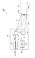
- FIG. 1 is a block diagram of a gating camera 20A according to the first embodiment.
- This gating camera 20A is mounted on a vehicle such as an automobile or motorcycle, and the output of the gating camera 20A is used to determine the type (category or class) of an object OBJ existing around the vehicle. .
- the gating camera 20A includes an illumination device (projector) 22, an image sensor 24, and a camera controller 26.
- FIG. The imaging by the gating camera 20A is performed by dividing the field of view into a plurality of N (N ⁇ 2) ranges RNG 1 to RNG N in the depth direction. Adjacent ranges may overlap in the depth direction of the field of view at their boundaries.
- the illumination device 22 illuminates the front of the vehicle with the probe light L1 in synchronization with the light emission timing signal S1 given from the camera controller 26.
- the probe light L1 is preferably infrared light, but is not limited to this, and may be visible light or ultraviolet light having a predetermined wavelength.
- a laser diode (LD) or an LED, for example, can be used for the illumination device 22 .
- the image sensor 24 includes a plurality of pixels, is capable of exposure control in synchronization with the exposure timing signal S2 given from the camera controller 26, and generates a raw image (RAW image) composed of a plurality of pixels.
- the image sensor 24 has sensitivity to the same wavelength as the probe light L1, and captures reflected light (return light) L2 reflected by the object OBJ.
- the slice image IMG i produced by the image sensor 24 for the i-th range RNG i is referred to as the raw image or primary image as appropriate to distinguish it from the slice image IMGs i which is the final output of the gating camera 20A. .
- the image sensor 24 is configured so that the effective shooting range can be controlled according to the shooting range control signal S3 from the camera controller 26 .
- the camera controller 26 controls the irradiation timing (light emission timing) of the probe light L1 by the illumination device 22 and the exposure timing by the image sensor 24 .
- the camera controller 26 can be implemented by combining a processor (hardware) such as a CPU (Central Processing Unit), MPU (Micro Processing Unit), or microcomputer, and a software program executed by the processor (hardware).
- a processor such as a CPU (Central Processing Unit), MPU (Micro Processing Unit), or microcomputer
- the image processing device 28 receives the raw image IMG_RAW i generated by the image sensor 24, performs necessary image processing, and generates a slice image IMGs i .
- the slice images IMGs may be the same as the raw image IMG_RAW, in which case the image processor 28 may be omitted.
- the camera controller 26 receives vehicle information INFO including at least vehicle speed information from the vehicle body side.
- the camera controller 26 controls the effective photographing range of the image sensor 24 according to the vehicle speed indicated by the vehicle information INFO.
- the imaging range control signal S3 is output to control the effective imaging range so that the lower the vehicle speed, the wider the angle of view, and the higher the vehicle speed, the narrower the angle of view.
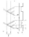
- FIG. 2 is a diagram for explaining the basic operation of the gating camera 20A.
- FIG. 2 shows how the i-th range RNG i is sensed as a range of interest (ROI).
- the illumination device 22 emits light during a light emission period ⁇ 1 between times t 0 and t 1 in synchronization with the light emission timing signal S1.
- ⁇ 1 between times t 0 and t 1 in synchronization with the light emission timing signal S1.
- dMINi be the distance from the gating camera 20A to the front boundary of range RNG i
- d MAXi be the distance to the rear boundary of range RNG i .
- TMINi 2 ⁇ d MINi /c is.
- c is the speed of light.
- T MAXi 2 ⁇ d MAXi /c is.
- a timing signal S2 is generated. This is one exposure operation.
- the camera controller 26 may repeatedly generate the light emission timing signal S1 and the exposure timing signal S2 at a predetermined cycle.
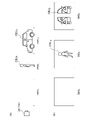
- FIGS. 3A and 3B are diagrams for explaining slice images obtained by the gating camera 20A.
- an object (pedestrian) OBJ2 exists in the range RNG2
- an object ( vehicle) OBJ3 exists in the range RNG3 .
- FIG. 3(b) shows a plurality of slice images IMG 1 to IMG 3 obtained in the situation of FIG. 3(a).
- the image sensor is exposed only by reflected light from the range RNG 1 , so no object image is captured in the slice image IMG 1.
- the image sensor When the slice image IMG 2 is captured, the image sensor is exposed only by reflected light from the range RNG 2 , so only the object image OBJ 2 appears in the slice image IMG 2 .
- the image sensor when slice image IMG 3 is captured, the image sensor is exposed only by reflected light from range RNG 3 , so only object image OBJ 3 appears in slice image IMG 3 .
- an object can be photographed separately for each range.
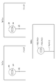
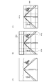
- FIGS. 4(a) to 4(c) are diagrams for explaining the control of the shooting range (angle of view) according to the vehicle speed.
- 4(a) shows the horizontal angle of view
- FIG. 4(b) shows the vertical angle of view
- FIG. 4(c) shows the effective imaging range of the image sensor.
- both the horizontal half angle of view ⁇ and the vertical half angle of view ⁇ are set wide.
- the effective imaging range A of the image sensor 24 is set wide so as to include all the pixels of the image sensor.
- the horizontal half angle of view ⁇ is determined according to the number x of pixels in the horizontal direction
- the half angle of view ⁇ in the vertical direction is determined according to the number y of pixels in the vertical direction.
- both the horizontal half angle of view ⁇ and the vertical half angle of view ⁇ are set narrow.
- the area B around the image sensor 24 is disabled, and only the central portion is cropped (trimmed) to narrow the effective imaging range A. As a result, the angle of view is set narrow.
- the camera controller 26 acquires the stopping distance L according to the vehicle speed v, and determines the effective photographing range of the image sensor 24 based on the stopping distance L and the minimum radius R of the curve existing on the road on which the vehicle is currently traveling. good too. As a result, even if braking is started after the gating camera 20A detects an object in front, it is possible to prevent the vehicle from colliding with the object.
- the stopping distance L can be calculated from equation (1) as the sum of the idling distance La and the braking distance Lb.
- L La+Lb (1)
- the idling distance La can be calculated by Equation (2).
- La tRES ⁇ v (2)
- t RES is the reaction time and v is the vehicle speed.
- the braking distance Lb can be calculated, for example, by Equation (3).
- Lb v′ 2 /(254 ⁇ ) (3)
- v' is the vehicle speed immediately before braking
- ⁇ is the coefficient of friction.
- the calculation may be performed in consideration of the road surface condition. This makes it possible to obtain an accurate braking distance Lb. If the road surface condition is not considered, the braking distance can be calculated by assuming that the coefficient of friction ⁇ is constant.
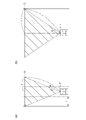
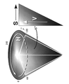
- FIG. 5 is a diagram showing a vehicle traveling on a curve. Assume that braking is started at point P while the vehicle is traveling on a curve with a radius of curvature R centered at point O. The actual curve is a clothoid curve, but here it is assumed to be a circular arc for simplification of calculation.
- the stopping distance is L
- the half angle of view of the gating camera 20A is set to be equal to or greater than the angle .theta., an object beyond the stopping point Q can be detected. That is, the effective photographing range of the image sensor 24 is controlled so that the half angle of view (unit: rad) falls within the range of L/(2R) as the lower limit.
- the half angle of view ⁇ of the gating camera 20A may be determined to be wider than L/(2R) and narrower than 1.2 ⁇ L/(2R).
- the stopping distance L is 77 m.
- the half angle of view should be 5.52 degrees or more.
- the stopping distance L increases to 99m.
- the half angle of view should be 7.13 degrees or more.
- the stopping distance L increases to 107 m.
- the half angle of view should be 7.66 degrees or more.
- the stopping distance L is 106 m.
- the half angle of view should be 4.28 degrees or more.
- the half angle of view was determined based on the curve with the minimum radius assumed on the road on which the vehicle is currently traveling, but this is not the only option.
- the half angle of view ⁇ may be controlled based on Equation (4) using the radius of curvature R of the curve that the vehicle is currently traveling on and the braking distance L.
- FIGS. 6A and 6B are diagrams showing a vehicle traveling on a straight road.
- a road with three lanes on each side is assumed.
- FIG. 6(a) shows driving in the left lane
- FIG. 6(b) shows driving in the center lane.
- x be the horizontal distance from the vehicle to the edge of the road in the lateral direction.
- x 1.5*l
- x 2.5*l.
- the half angle of view ⁇ of the gating camera 20A may be determined to be wider than arcsin(x/L) and narrower than 1.2 ⁇ arcsin(x/L).
- the coefficient ⁇ (1 ⁇ 1.2) the half angle of view ⁇ may be determined according to Equation (5).
- ⁇ ⁇ arcsin(x/L) (5)
- the distance x is determined using the driving lane of the vehicle as a parameter, it may not be easy for the camera controller 26 to obtain the distance x. In that case, regardless of the actual driving lane, assuming that the driver is driving along the extreme diagonal line as shown in FIG. can be calculated.
- the number of lanes and the width l of the diagonal line may be acquired from the car navigation system or may be acquired from outside the vehicle through wireless communication.
- a representative distance x may be determined as a constant and stored in the camera controller 26 in consideration of various assumed roads.
- the half angle of view is 12.8 degrees when the effective imaging range of the image sensor 24 is maximized.
- the half angle of view changes in the range of 4 to 10 degrees, which is 30 to 80% of the original half angle of view.
- the effective photographing range (angle of view) is controlled according to the vehicle speed with respect to the horizontal and vertical axes, but the angle of view/effective photographing range may be changed only in the horizontal direction. .
- the effective photographing range is controlled according to the vehicle speed for each of the curve and the straight road, but this is not the only option.
- the control of the effective photographing range based on vehicle speed may be disabled, the effective photographing range may be fixed at the maximum, and the effective photographing range may be controlled based on vehicle speed only for straight roads.
- the effective imaging range (angle of view) is controlled based on a first relational expression f(v) with vehicle speed v as an argument, and for straight roads, another second
- the effective photographing range (angle of view) is controlled based on the relational expression g(v).
- Formula (4) is an example of relational expression f(v)
- formula (5) is an example of relational expression g(v).
- L in equations (4) and (5) is a function of v.
- the effective photographing range and thus the angle of view may be controlled based on a common relational expression h(v) with at least the vehicle speed v as an argument.
- the relational expression h(v) in this case is h(v) ⁇ max(f(v), g(v)) should be determined so as to satisfy max() is a function that indicates the larger one.
- the control of the effective imaging range based on vehicle speed may be disabled and the effective imaging range may be fixed at the maximum.
- FIG. 7 is a block diagram of a gating camera 20B according to the second embodiment.
- This gating camera 20B is mounted on a vehicle such as an automobile or motorcycle, and the output of the gating camera 20B is used to determine the type (category or class) of an object OBJ existing around the vehicle. .
- the gating camera 20B includes an illumination device (projector) 22, an image sensor 24, a camera controller 26, and an image processing device .
- the imaging by the gating camera 20B is performed by dividing the field of view into a plurality of N (N ⁇ 2) ranges RNG 1 to RNG N in the depth direction. Adjacent ranges may overlap in the depth direction of the field of view at their boundaries.
- the illumination device 22 illuminates the front of the vehicle with the probe light L1 in synchronization with the light emission timing signal S1 given from the camera controller 26.
- the probe light L1 is preferably infrared light, but is not limited to this, and may be visible light or ultraviolet light having a predetermined wavelength.
- a laser diode (LD) or an LED, for example, can be used for the illumination device 22 .
- the image sensor 24 includes a plurality of pixels, is capable of exposure control in synchronization with the exposure timing signal S2 given from the camera controller 26, and generates a raw image (RAW image) composed of a plurality of pixels.
- the image sensor 24 has sensitivity to the same wavelength as the probe light L1, and captures reflected light (return light) L2 reflected by the object OBJ.
- the image sensor 24 is assumed to be a monochrome IR sensor.
- the camera controller 26 controls the irradiation timing (light emission timing) of the probe light L1 by the illumination device 22 and the exposure timing by the image sensor 24 .
- the camera controller 26 can be implemented by combining a processor (hardware) such as a CPU (Central Processing Unit), MPU (Micro Processing Unit), or microcomputer, and a software program executed by the processor (hardware).
- a processor such as a CPU (Central Processing Unit), MPU (Micro Processing Unit), or microcomputer
- the image processing device 28 receives the raw image IMG_RAW i generated by the image sensor 24, performs necessary image processing, and generates a slice image IMGs i .
- Raw images IMG_RAW generated in each range may be used as they are as slice images IMGs.
- the image processing device 28 also synthesizes a plurality of slice images IMGs 1 to IMGs N (or IMG_RAW 1 to IMG_RAW N ) to generate a synthesized image IMGc.
- RNG 1 to RNG N are assigned N different colors C 1 to C N .
- Each pixel of the composite image IMGc is obtained by weighting and adding the N colors C 1 to C N with coefficients based on the pixel values v 1 to v N of the corresponding pixels of the N slice images IMGs 1 to IMGs N. has a value.
- FIG. 8 is a diagram for explaining the basic operation of the gating camera 20B.
- FIG. 8 shows how the i-th range RNG i is sensed as a range of interest (ROI).
- the illumination device 22 emits light during a light emission period ⁇ 1 between times t 0 and t 1 in synchronization with the light emission timing signal S1.
- ⁇ 1 between times t 0 and t 1 in synchronization with the light emission timing signal S1.
- dMINi be the distance from the gating camera 20B to the front boundary of range RNG i
- d MAXi be the distance to the rear boundary of range RNG i .
- TMINi 2 ⁇ d MINi /c is.
- c is the speed of light.
- T MAXi 2 ⁇ d MAXi /c is.
- a timing signal S2 is generated. This is one exposure operation.
- the camera controller 26 may repeatedly generate the light emission timing signal S1 and the exposure timing signal S2 at a predetermined cycle.
- FIGS. 9A and 9B are diagrams for explaining slice images obtained by the gating camera 20B.
- an object (pedestrian) OBJ2 exists in the range RNG2
- an object ( vehicle) OBJ3 exists in the range RNG3 .
- FIG. 9(b) shows a plurality of slice images IMG 1 to IMG 3 obtained in the situation of FIG. 9(a).
- the image sensor is exposed only by reflected light from the range RNG 1 , so no object image is captured in the slice image IMG 1.
- FIG. 9A shows a plurality of slice images IMG 1 to IMG 3 obtained in the situation of FIG. 9(a).
- the image sensor When the slice image IMG 2 is captured, the image sensor is exposed only by reflected light from the range RNG 2 , so only the object image OBJ 2 appears in the slice image IMG 2 .
- the image sensor when slice image IMG 3 is captured, the image sensor is exposed only by reflected light from range RNG 3 , so only object image OBJ 3 appears in slice image IMG 3 .
- an object can be photographed separately for each range.
- FIGS. 10(a) to 10(d) are diagrams explaining a composite image and a conventional distance image.
- FIG. 10(a) shows the actual field of view.
- FIG. 10(b) shows an IR image taken of the field of view of FIG. 10(a).
- FIG. 10(c) shows a range image generated by a conventional ToF camera.
- FIG. 10(d) shows a composite image IMGc generated in this embodiment.
- the composite image IMGc includes characters and figures written on the surface of objects existing in the same range. Therefore, more detailed information about the object can be acquired based on the composite image IMGc by image processing in the latter stage. Alternatively, by displaying the composite image IMGc on the display, the user can recognize the type of the sign and the instruction.
- Example 2.1 synthesis processing is performed using the RGB color system.
- a plurality of colors (R 1 , G 1 , B 1 ) to (R N , G N , B N ) are assigned corresponding to the plurality of ranges RNG 1 to RNG N.
- FIG. 11 is a diagram illustrating a plurality of colors assigned to a plurality of ranges in the RGB color system. For example, the following colors can be used as colors corresponding to ranges. red (1,0,0) Yellow (1,1,0) green (0,1,0) cyan (0,1,1) blue (0,0,1) magenta (1,0,1)
- the i-th (1 ⁇ i ⁇ N) color (R i , G i , B i ) and the (i+1)-th color (R i+1 , G i+1 , B i+1 ) are one element among R, G, and B have different values and the remaining two elements have the same value. In the chart of FIG. 11, two adjacent colors satisfy this relationship. In this embodiment, each color component (R, G, B in this example) shall be normalized to one.
- Red and yellow have the same two elements of R and B, and one element of G is different.
- green and cyan are compared, two elements of R and G are equal and one element of B is different.
- N of ranges is 6 or less
- N adjacent ones of the 6 colors from red to magenta should be used. Note that magenta and red are adjacent to each other.
- white (1, 1, 1) and black (0, 0, 0) may be used.
- White (1,1,1) is related to yellow, cyan, and magenta by one factor.
- Black (0,0,0) is related to red, green, and blue by one factor.
- neutral colors can be used.
- colors can be defined between yellow and green, green and cyan, cyan and blue, and blue and magenta.
- the pixel value (R, G, B) of each pixel of the composite image IMGc is represented by the following formula using the pixel value v of the corresponding pixel of the plurality of slice images.
- FIG. 12 is a diagram for explaining the composition of the composite image IMGc.
- any object point (object) appears only in the slice image corresponding to the range in which it exists. In this case, if a pixel in a slice image has a non-zero pixel value, the pixel value of that pixel in another slice image is zero.
- FIG. 12 shows two slice images IMGs 1 and IMGs 2 corresponding to two ranges RNG 1 and RNG 2 and a combined image IMGc.
- the first range RNG 1 is assigned the color red (1,0,0) and the second range RNG 2 is assigned the color yellow (1,1,0).
- slice images IMGs 1 and IMGs 2 are 8-bit monochrome IR images
- the pixel value of each pixel is represented by 256 gradations from 0 to 255.
- the numbers in slice images IMGs 1 and IMGs 2 in FIG. 12 represent pixel values for each region.
- the slice image IMGs 1 is colored red by multiplying the pixel value of each pixel by (1,0,0). That is, in the synthetic image IMGc, an object existing in the range RNG 1 is represented in the range from black (0,0,0) to red (1,0,0).
- slice image IMGs2 is colored yellow by multiplying the pixel value of each pixel by (1,1,0). That is, in the synthetic image IMGc, the object existing in the range RNG 2 is represented in the range from black (0,0,0) to yellow (1,1,0).
- the color system represents the range, and the brightness within the same color system represents the reflectance of the object.
- An object point existing near the boundary of the range may be captured across two adjacent slice images.
- the same pixels in the two slice images have non-zero pixel values.
- adjacent ranges are defined to overlap in the depth direction, the same pixels in the two slice images have non-zero pixel values.
- FIGS. 13A and 13B are diagrams for explaining synthesis processing when the same object straddles a plurality of slice images.
- the pixel value of the slice image IMGs1 is 120
- the pixel value of the slice image IMGs2 is 30.
- an object captured across two slice images IMGs can be multi-gradated using colors obtained by blending the two colors (1,0,0) and (1,1,0). can be expressed. This makes it possible to identify the content of the sign.
- FIG. 14 is a diagram illustrating an example of correspondence relationships between a plurality of ranges and colors in Example 2.1.
- Range RNG 1 ranges from 10 to 15 m and is assigned red (1,0,0). Red, yellow, green, cyan, and blue are divided into five, and intermediate colors are used.
- Example 2.2 the Yxy color system (also referred to as the XYZ color system) is used.
- FIG. 15 is a diagram illustrating a plurality of colors assigned to a plurality of ranges in the Yxy color system. The color for the i-th range is defined as the chromaticity point (x i , y i ) on the xy chromaticity diagram without using the luminance Y in the Yxy color system.
- a plurality of chromaticity points located on the sides (including the vertices) of the triangle with may be assigned to a plurality of ranges.
- a plurality of A chromaticity point may also be used.
- the luminance Y of the composite image IMGc is the sum of the pixel values of the slice images.
- Chromaticity points (x 1 , y 1 ) to (x N , y N ) are assigned to the ranges RNG 1 to RNG N , and the pixel value of a pixel in the slice images IMGs 1 to IMGs N is v 1 ⁇ vN .
- the pixel value of a target pixel in slice image IMGs1 is 80
- the pixel value of the same target pixel in slice image IMGs2 is 160.
- the chromaticity point of the synthesized image IMGc is a point obtained by internally dividing the two chromaticity points assigned to the slice images.
- FIG. 16 is a diagram showing an example of correspondence relationships between multiple ranges and colors in Example 2.2.
- FIG. 17 is a diagram illustrating an example of correspondence relationships between a plurality of ranges and colors in Example 2.3.
- the N colors assigned to the N ranges are determined to have different hues H (Hue) in the HSV color system.
- Hue H can take values from 0 to 360 degrees.
- the brightness V (Value) of the synthesized image IMGc is the sum of the pixel values of the slice images.
- the saturation S of each pixel of the composite image IMGc is a predetermined constant S0.
- the hue H of each pixel of the composite image IMGc is obtained by weighting and adding the hues H 1 to H N assigned to the plurality of slice images with the pixel value v.
- the pixel value of a target pixel in slice image IMGs1 is 80, and the pixel value of the same target pixel in slice image IMGs2 is 160.
- the hue H of the synthesized image IMGc is a point obtained by internally dividing the two hues assigned to the slice images.
- FIG. 18 is a diagram showing an example of correspondence relationships between multiple ranges and colors in Example 2.3.
- FIG. 19 is a block diagram of a gating camera 20C according to the third embodiment.
- This gating camera 20C is mounted on a vehicle such as an automobile or motorcycle, and the output of the gating camera 20C is used to determine the type (category or class) of an object OBJ existing around the vehicle. .
- the gating camera 20 ⁇ /b>C includes an illumination device (projector) 22 , an image sensor 24 and a camera controller 26 .
- the imaging by the gating camera 20C is performed by dividing the visual field into a plurality of N (N ⁇ 2) ranges RNG 1 to RNG N in the depth direction. Adjacent ranges may overlap in the depth direction of the field of view at their boundaries.
- the illumination device 22 illuminates the front of the vehicle with the probe light L1 in synchronization with the light emission timing signal S1 given from the camera controller 26.
- the probe light L1 is preferably infrared light, but is not limited to this, and may be visible light or ultraviolet light having a predetermined wavelength.
- a laser diode (LD) or an LED, for example, can be used for the illumination device 22 .
- the illumination device 22 is configured to be capable of light distribution control by dividing the virtual vertical screen 900 into a plurality of regions 902 and switching between irradiation and non-irradiation of the probe light L1 for each region.
- a light distribution control signal S4 is input from the camera controller 26 to the lighting device 22 to designate which region should be irradiated with the probe light.
- the illumination device 22 selects one or a plurality of areas specified by the light distribution control signal S4, irradiates the selected areas (referred to as irradiation areas) with the probe light L1, and forms a light distribution pattern PTN.
- the image sensor 24 includes a plurality of pixels, is capable of exposure control in synchronization with the exposure timing signal S2 given from the camera controller 26, and generates a raw image (RAW image) composed of a plurality of pixels.
- the image sensor 24 has sensitivity to the same wavelength as the probe light L1, and captures reflected light (return light) L2 reflected by the object OBJ.
- the slice image IMG i produced by the image sensor 24 for the i-th range RNG i is referred to as the raw image or primary image as appropriate to distinguish it from the slice image IMGs i which is the final output of the gating camera 20C. .
- the camera controller 26 controls the irradiation timing (light emission timing) of the probe light L1 by the illumination device 22 and the exposure timing by the image sensor 24 .
- the camera controller 26 can be implemented by combining a processor (hardware) such as a CPU (Central Processing Unit), MPU (Micro Processing Unit), or microcomputer, and a software program executed by the processor (hardware).
- a processor such as a CPU (Central Processing Unit), MPU (Micro Processing Unit), or microcomputer
- the image processing device 28 receives the raw image IMG_RAW i generated by the image sensor 24, performs necessary image processing, and generates a slice image IMGs i .
- the slice images IMGs may be the same as the raw image IMG_RAW, in which case the image processor 28 may be omitted.
- the camera controller 26 selects an area to be irradiated with the probe light L1 from among a plurality of areas 902 on the virtual vertical screen 900 according to the driving scene of the vehicle equipped with the gating camera 20C, and outputs the light distribution control signal S4. to generate
- FIG. 20 is a diagram for explaining the basic operation of the gating camera 20C.
- FIG. 20 shows how the i-th range RNG i is sensed as a range of interest (ROI).
- the illumination device 22 emits light during a light emission period ⁇ 1 between times t 0 and t 1 in synchronization with the light emission timing signal S1.
- ⁇ 1 between times t 0 and t 1 in synchronization with the light emission timing signal S1.
- dMINi be the distance from the gating camera 20C to the front boundary of range RNG i
- d MAXi be the distance to the rear boundary of range RNG i .
- TMINi 2 ⁇ d MINi /c is.
- c is the speed of light.
- T MAXi 2 ⁇ d MAXi /c is.
- a timing signal S2 is generated. This is one exposure operation.
- the camera controller 26 may repeatedly generate the light emission timing signal S1 and the exposure timing signal S2 at a predetermined cycle.
- FIGS. 21A and 21B are diagrams for explaining slice images obtained by the gating camera 20C.
- an object (pedestrian) OBJ2 exists in the range RNG2
- an object ( vehicle) OBJ3 exists in the range RNG3 .
- FIG. 21(b) shows a plurality of slice images IMG 1 to IMG 3 obtained in the situation of FIG. 21(a).
- the image sensor is exposed only by reflected light from the range RNG 1 , so no object image is captured in the slice image IMG 1.
- the image sensor When the slice image IMG 2 is captured, the image sensor is exposed only by reflected light from the range RNG 2 , so only the object image OBJ 2 appears in the slice image IMG 2 .
- the image sensor when slice image IMG 3 is captured, the image sensor is exposed only by reflected light from range RNG 3 , so only object image OBJ 3 appears in slice image IMG 3 .
- the object can be photographed separately for each range.
- the power consumption can be reduced by stopping the irradiation of the probe light in such a range.
- the image sensor 24 does not need to shoot the range that is not irradiated with the probe light. Therefore, the camera controller 26 may change the photographing range (readout range) of the image sensor 24 in conjunction with the light distribution of the probe light. Thereby, the power consumption of the image sensor 24 can be reduced. In addition, since the image data reading and transfer time can be shortened, the frame rate can be increased.
- FIGS. 22(a) to (c) are diagrams for explaining an example of control of the irradiation area according to the driving scene.
- FIG. 22(a) shows a field of view in a certain driving scene.
- FIG. 22(b) shows the field of view of FIG. 22(a) overlaid with a virtual vertical screen 900 divided into a plurality of regions.
- the upper part of the field of view is occupied by the sky, and it is difficult to imagine that other vehicles, pedestrians, signs, etc., to be detected by the gating camera 20C exist in that range.
- area 904 of virtual vertical screen 900 is the portion corresponding to the sky.
- FIG. 22(c) shows the light distribution pattern PTN of the probe light L1.
- a range 904 corresponding to the sky is excluded from the irradiation region 906 of the probe light.
- the slice images IMGs 1 to IMGs N captured by the gating camera 20C show objects existing in portions other than the sky.
- FIGS. 23(a) to (c) are diagrams explaining another example of control of the irradiation area according to the driving scene.
- 23(a) shows the field of view in a driving scene
- FIG. 23(b) shows the field of view of FIG. 23(a) superimposed on a virtual vertical screen 900 divided into a plurality of regions.
- FIG. 23(c) shows the light distribution pattern PTN of the probe light L1 in the driving scene of FIG. 23(a).
- FIG. 23(a) is an example of the field of view, and this example shows that there are only natural objects such as trees outside the road, and in this case, the objects outside the road are less interesting. It can be said. The same is true when there is only an artificial object such as a building outside the road.
- Another example is a driving scene in which both sides of the road are covered with guardrails and side walls, and objects outside the guardrails and side walls cannot enter the road. interest is low.
- the range 904 of the virtual vertical screen 900 is the part corresponding to the sky.
- Ranges 908A and 908B indicate the outside of the road.
- a range 904 corresponding to the sky and ranges 908A and 908B outside the road are excluded from the irradiation area 906 of the probe light.
- the slice images IMGs 1 to IMGs N captured by the gating camera 20C show objects existing outside the sky and roads.
- FIG. 22(a) shows a one-lane road, but this tendency is particularly pronounced in the case of two-lane roads.
- the area outside the road on the oncoming lane side may be excluded from the irradiation area of the probe light.
- the camera controller 26 may control the light distribution of the probe light based on the slice images IMGs 1 to IMGs N captured by the gating camera 20C.
- FIG. 24 is a diagram for explaining light distribution control by the camera controller 26.
- the camera controller 26 alternates between the reference frame REF and subsequent normal frames for m frames (where m ⁇ 1).
- the reference frame and the normal frame each contain a full range of sensing.
- the camera controller 26 determines the driving scene and determines the light distribution of the probe light based on the slice images IMGs 1 to IMGs N obtained in the reference frame REF.
- the camera controller 26 may determine that the upper portion of the image, in all of the slice images IMGs 1 to IMGs N , where the pixel values are smaller than a predetermined threshold, is empty.
- sensing is repeated as a normal frame for the following m frames.
- the power consumption increases during the reference frame and decreases during the normal frame according to the driving scene.
- the gating camera 20C can form a light distribution suitable for the driving scene and reduce power consumption.
- the area 908 outside the road may be determined based on the slice images IMGs, but in that case, advanced image processing is required. Therefore, the area 908 outside the road may be determined by referring to the map information. For example, when high-precision three-dimensional map information is available, the camera controller 26 can accurately reproduce the field of view in each driving scene, so the determination of the off-road range 908 is easy. Light distribution control that is not based on slice images (for example, based on three-dimensional map information) may be performed in a reference frame or in a normal frame.
- the gating camera 20C may dynamically control the parameter m according to road conditions.
- the camera controller 26 may reduce m around slopes.
- the percentage of sky included in the field of view of the camera changes greatly and frequently. Therefore, in such a situation, appropriate sensing becomes possible by reducing m and frequently updating the light distribution of the probe light.
- Whether or not it is around a slope may be determined based on three-dimensional map information. Alternatively, determination may be made based on the output of a tilt sensor (acceleration sensor) mounted on the vehicle.
- FIG. 25 is a diagram for explaining changes in the horizontal field of view while driving on a curve.
- the field of view changes by 2.68 degrees, 0.26 degrees, 0.13 degrees, 0.054 degrees, and 0.027 degrees. If the change in field of view is about 0.26 degrees, it can be said that the position of the sky hardly changes. Therefore, the upper limit of m may be set such that the reference frame occurs at least every 0.1 seconds.
- camera controller 26 may dynamically control the interval between occurrences of reference frames m during curve travel, based on the radius of curvature of the curve.
- v be the vehicle speed
- R be the radius of curvature
- ⁇ MAX (rad) be the permissible range of change in the field of view between a certain reference frame and the next reference frame.
- t MAX the upper limit of the time interval of the reference frame
- FIG. 26 is a diagram showing a configuration example of the illumination device 22.
- the lighting device 22 includes a plurality of semiconductor light-emitting elements 60 , an optical system 62 and a lighting circuit 64 .
- a plurality of semiconductor light emitting devices 60 are arranged in an array.
- the array may be one-dimensional or two-dimensional.
- An LD laser diode
- LED light emitting diode
- organic EL Electro Luminescence
- the optical system 62 projects the light emitted from each of the plurality of semiconductor light emitting elements 60 onto a corresponding one of the plurality of regions on the virtual vertical screen.
- the configuration of the optical system 62 is not particularly limited, and may be an array of lenses or a light guide provided with a plurality of steps.
- the lighting circuit 64 selects a plurality of semiconductor light emitting elements 60 to be driven according to the light distribution control signal S4. A driving current is supplied to the selected semiconductor light emitting element 60 in synchronization with the light emission timing signal S1.
- the lighting circuit 64 may include multiple constant current drivers 66 corresponding to the multiple semiconductor light emitting devices 60 . Among the plurality of constant current drivers 66, some become active according to the light distribution control signal S4, and the active constant current drivers 66 generate drive current in synchronization with the light emission timing signal S1.
- the light distribution of the probe light is divided two-dimensionally and controlled, but it may be divided only in the vertical direction and controlled only by excluding the sky portion.
- control to exclude the outside of the road may be performed without performing the control to exclude the sky portion.
- gating cameras 20A to 20C (hereinafter collectively referred to as gating cameras 20) according to Embodiments 1 to 3 will be described.
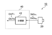
- FIG. 27 is a block diagram of the sensing system 10. As shown in FIG.
- the sensing system 10 includes an arithmetic processing unit 40 in addition to the gating camera 20 described above.
- the sensing system 10 is an object detection system that is mounted on a vehicle such as an automobile or a motorcycle and determines the type (category or class) of an object OBJ existing around the vehicle.
- a plurality of slice images IMGs 1 to IMGs N corresponding to a plurality of ranges RNG 1 to RNG N are generated by the gating camera 20 . Only the objects included in the corresponding range RNG i appear in the i-th slice image IMGs i .
- the arithmetic processing unit 40 is configured to be able to identify the type of object based on the multiple slice images IMGs 1 to IMGs N corresponding to the multiple ranges RNG 1 to RNG N obtained by the gating camera 20 .
- the processing unit 40 has a classifier 42 implemented based on a trained model generated by machine learning.
- the processing unit 40 may include multiple classifiers 42 optimized for each range.
- the algorithm of the classifier 42 is not particularly limited, YOLO (You Only Look Once), SSD (Single Shot MultiBox Detector), R-CNN (Region-based Convolutional Neural Network), SPPnet (Spatial Pyramid Pooling), Faster R-CNN , DSSD (Deconvolution-SSD), Mask R-CNN, etc., or algorithms to be developed in the future.
- the arithmetic processing unit 40 can be implemented by combining a processor (hardware) such as a CPU (Central Processing Unit), MPU (Micro Processing Unit), or microcomputer, and a software program executed by the processor (hardware).
- the arithmetic processing unit 40 may be a combination of multiple processors. Alternatively, the arithmetic processing unit 40 may be composed only of hardware.
- the functions of the arithmetic processing unit 40 and the functions of the image processing unit 28 may be implemented in the same processor.
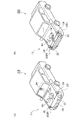
- FIG. 28(a) and (b) are diagrams showing an automobile 300 equipped with the gating camera 20.
- FIG. Please refer to FIG.
- the automobile 300 includes headlamps (lamps) 302L and 302R.
- the lighting device 22 of the gating camera 20 may be built into at least one of the left and right headlamps 302L and 302R.
- the image sensor 24 can be attached to a part of the vehicle, for example behind the rearview mirror. Alternatively, the image sensor 24 may be provided on the front grille or front bumper.
- the camera controller 26 may be provided inside the vehicle, in the engine room, or incorporated in the headlamps 302L and 302R.
- the image sensor 24 may be incorporated in either of the left and right headlamps 302L, 302R together with the lighting device 22.
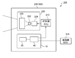
- FIG. 29 is a block diagram showing a vehicle lamp 200 including the sensing system 10.
- the vehicle lamp 200 constitutes a lamp system 304 together with the vehicle-side ECU 310 .
- the vehicle lamp 200 includes a lamp side ECU 210 and a lamp unit 220 .
- the lamp unit 220 is low beam or high beam, and includes a light source 222 , a lighting circuit 224 and an optical system 226 . Further, the vehicle lamp 200 is provided with the sensing system 10 .
- Information about the object OBJ detected by the sensing system 10 may be used for light distribution control of the vehicle lamp 200 .
- the lamp-side ECU 210 generates an appropriate light distribution pattern based on the information about the type and position of the object OBJ generated by the sensing system 10 .
- the lighting circuit 224 and the optical system 226 operate so as to obtain the light distribution pattern generated by the lamp-side ECU 210 .
- the arithmetic processing unit 40 of the sensing system 10 may be provided outside the vehicle lamp 200, that is, on the vehicle side.
- Information regarding the object OBJ detected by the sensing system 10 may also be transmitted to the vehicle-side ECU 310 .
- the vehicle-side ECU 310 may use this information for automatic driving and driving assistance.
- the present invention relates to gating cameras.
Landscapes
- Engineering & Computer Science (AREA)
- Physics & Mathematics (AREA)
- General Physics & Mathematics (AREA)
- Computer Networks & Wireless Communication (AREA)
- Radar, Positioning & Navigation (AREA)
- Remote Sensing (AREA)
- Electromagnetism (AREA)
- Mechanical Engineering (AREA)
- Optical Radar Systems And Details Thereof (AREA)
- Studio Devices (AREA)
Priority Applications (3)
| Application Number | Priority Date | Filing Date | Title |
|---|---|---|---|
| JP2023517482A JPWO2022230760A1 (https=) | 2021-04-27 | 2022-04-21 | |
| CN202280031402.0A CN117222917A (zh) | 2021-04-27 | 2022-04-21 | 门控摄像头、感测系统、车辆用灯具 |
| US18/288,516 US20240210531A1 (en) | 2021-04-27 | 2022-04-21 | Gating camera, sensing system, and vehicle lamp |
Applications Claiming Priority (6)
| Application Number | Priority Date | Filing Date | Title |
|---|---|---|---|
| JP2021075213 | 2021-04-27 | ||
| JP2021-075213 | 2021-04-27 | ||
| JP2021-079976 | 2021-05-10 | ||
| JP2021079976 | 2021-05-10 | ||
| JP2021088715 | 2021-05-26 | ||
| JP2021-088715 | 2021-05-26 |
Publications (1)
| Publication Number | Publication Date |
|---|---|
| WO2022230760A1 true WO2022230760A1 (ja) | 2022-11-03 |
Family
ID=83846874
Family Applications (1)
| Application Number | Title | Priority Date | Filing Date |
|---|---|---|---|
| PCT/JP2022/018484 Ceased WO2022230760A1 (ja) | 2021-04-27 | 2022-04-21 | ゲーティングカメラ、センシングシステム、車両用灯具 |
Country Status (3)
| Country | Link |
|---|---|
| US (1) | US20240210531A1 (https=) |
| JP (1) | JPWO2022230760A1 (https=) |
| WO (1) | WO2022230760A1 (https=) |
Cited By (1)
| Publication number | Priority date | Publication date | Assignee | Title |
|---|---|---|---|---|
| WO2024048275A1 (ja) * | 2022-08-31 | 2024-03-07 | ソニーセミコンダクタソリューションズ株式会社 | 情報処理装置、情報処理方法および車室内監視装置 |
Families Citing this family (3)
| Publication number | Priority date | Publication date | Assignee | Title |
|---|---|---|---|---|
| DE102021002915A1 (de) * | 2021-06-07 | 2022-12-08 | Daimler Truck AG | Verfahren zum Betreiben einer Gated-Kamera, Steuervorrichtung zur Durchführung eines solchen Verfahrens, Sichtweitenmessvorrichtung mit einer solchen Steuervorrichtung und Kraftfahrzeug mit einer solchen Sichtweitenmessvorrichtung |
| US12305846B1 (en) * | 2024-07-08 | 2025-05-20 | 2468862 Ontario Inc. | Lightbar with integrated camera system |
| JP7830564B2 (ja) * | 2024-07-25 | 2026-03-16 | キヤノン株式会社 | 撮像装置、撮像方法 |
Citations (4)
| Publication number | Priority date | Publication date | Assignee | Title |
|---|---|---|---|---|
| JP2010061304A (ja) * | 2008-09-02 | 2010-03-18 | Calsonic Kansei Corp | 車両用距離画像データ生成装置 |
| US20160350601A1 (en) * | 2015-06-01 | 2016-12-01 | Brightway Vision Ltd. | Image enhancements for vehicle imaging systems |
| WO2019197203A1 (en) * | 2018-04-11 | 2019-10-17 | Koninklijke Philips N.V. | Systems and methods for generating enhanced diagnostic images from 3d medical image data |
| US20190346537A1 (en) * | 2016-09-20 | 2019-11-14 | Brightway Vision Ltd | Pulsed light illuminator having a configurable setup |
-
2022
- 2022-04-21 JP JP2023517482A patent/JPWO2022230760A1/ja active Pending
- 2022-04-21 US US18/288,516 patent/US20240210531A1/en active Pending
- 2022-04-21 WO PCT/JP2022/018484 patent/WO2022230760A1/ja not_active Ceased
Patent Citations (4)
| Publication number | Priority date | Publication date | Assignee | Title |
|---|---|---|---|---|
| JP2010061304A (ja) * | 2008-09-02 | 2010-03-18 | Calsonic Kansei Corp | 車両用距離画像データ生成装置 |
| US20160350601A1 (en) * | 2015-06-01 | 2016-12-01 | Brightway Vision Ltd. | Image enhancements for vehicle imaging systems |
| US20190346537A1 (en) * | 2016-09-20 | 2019-11-14 | Brightway Vision Ltd | Pulsed light illuminator having a configurable setup |
| WO2019197203A1 (en) * | 2018-04-11 | 2019-10-17 | Koninklijke Philips N.V. | Systems and methods for generating enhanced diagnostic images from 3d medical image data |
Cited By (1)
| Publication number | Priority date | Publication date | Assignee | Title |
|---|---|---|---|---|
| WO2024048275A1 (ja) * | 2022-08-31 | 2024-03-07 | ソニーセミコンダクタソリューションズ株式会社 | 情報処理装置、情報処理方法および車室内監視装置 |
Also Published As
| Publication number | Publication date |
|---|---|
| JPWO2022230760A1 (https=) | 2022-11-03 |
| US20240210531A1 (en) | 2024-06-27 |
Similar Documents
| Publication | Publication Date | Title |
|---|---|---|
| WO2022230760A1 (ja) | ゲーティングカメラ、センシングシステム、車両用灯具 | |
| EP3888965B1 (en) | Head-up display, vehicle display system, and vehicle display method | |
| US11639138B2 (en) | Vehicle display system and vehicle | |
| US10634317B2 (en) | Dynamic control of vehicle lamps during maneuvers | |
| JP4970516B2 (ja) | 周囲確認支援装置 | |
| CN107264402B (zh) | 环视提供设备和包括其的车辆 | |
| CN100401129C (zh) | 用于以红外图像和可见图像与环境相关的结合来显示车辆环境的方法和装置 | |
| CN108025672B (zh) | 可预先给定的光图案的投影 | |
| JP5680573B2 (ja) | 車両の走行環境認識装置 | |
| CN104512411B (zh) | 车辆控制系统及图像传感器 | |
| CN113243016A (zh) | 物体识别系统、运算处理装置、汽车、车辆用灯具、分类器的学习方法 | |
| JP5115792B2 (ja) | 画像処理装置および方法、並びに、プログラム | |
| CN104041022B (zh) | 图像处理装置 | |
| US20050134479A1 (en) | Vehicle display system | |
| US20120062746A1 (en) | Image Processing Apparatus | |
| US20090073258A1 (en) | Device intended to support the driving of a motor vehicle comprising a system capable of capturing stereoscopic images | |
| JPWO2019194256A1 (ja) | 演算処理装置、オブジェクト識別システム、学習方法、自動車、車両用灯具 | |
| JP2009071789A (ja) | 車両周辺監視システム | |
| WO2017221945A1 (ja) | 表示装置、表示システム、移動体、および表示方法 | |
| JP6847781B2 (ja) | 画像処理装置 | |
| CN114072699A (zh) | 信息处理系统、传感器系统、信息处理方法以及程序 | |
| JP2003078908A (ja) | 車両における視界を改善する方法および装置 | |
| US8170284B2 (en) | Apparatus and method for displaying image of view in front of vehicle | |
| CN117222917A (zh) | 门控摄像头、感测系统、车辆用灯具 | |
| JP5904825B2 (ja) | 画像処理装置 |
Legal Events
| Date | Code | Title | Description |
|---|---|---|---|
| 121 | Ep: the epo has been informed by wipo that ep was designated in this application |
Ref document number: 22795673 Country of ref document: EP Kind code of ref document: A1 |
|
| ENP | Entry into the national phase |
Ref document number: 2023517482 Country of ref document: JP Kind code of ref document: A |
|
| WWE | Wipo information: entry into national phase |
Ref document number: 18288516 Country of ref document: US |
|
| WWE | Wipo information: entry into national phase |
Ref document number: 202280031402.0 Country of ref document: CN |
|
| NENP | Non-entry into the national phase |
Ref country code: DE |
|
| 122 | Ep: pct application non-entry in european phase |
Ref document number: 22795673 Country of ref document: EP Kind code of ref document: A1 |