以下、添付図面を参照して実施形態を詳しく説明する。なお、以下の実施形態は特許請求の範囲に係る発明を限定するものではなく、また実施形態で説明されている特徴の組み合わせの全てが発明に必須のものとは限らない。実施形態で説明されている複数の特徴のうち二つ以上の特徴が任意に組み合わされてもよい。また、同一若しくは同様の構成には同一の参照番号を付し、重複した説明は省略する。
Hereinafter, embodiments will be described in detail with reference to the accompanying drawings. It should be noted that the following embodiments do not limit the invention according to the claims, and not all combinations of features described in the embodiments are essential to the invention. Two or more of the features described in the embodiments may be combined arbitrarily. Also, the same or similar configurations are denoted by the same reference numerals, and redundant explanations are omitted.
<エアロゾル生成装置の構成>
以下の説明では、ユーザによる操作部に対する操作のうちの少なくとも一部の操作を制限するロック機能を有するエアロゾル生成装置を例に説明する。
<Configuration of aerosol generator>
In the following description, an example of an aerosol generating device having a lock function that restricts at least part of the user's operations on the operation unit will be described.
(エアロゾル生成装置の外観)
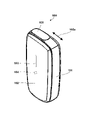
図1は、本実施形態に係るエアロゾル生成装置100の外観の一例を示している。エアロゾル生成装置100は、例えば、本体101、前面パネル102、表示窓103、操作部材104及びスライダ105を含む。
(Appearance of aerosol generator)
FIG. 1 shows an example of the appearance of an aerosol generator 100 according to this embodiment. The aerosol generator 100 includes, for example, a main body 101, a front panel 102, a display window 103, an operating member 104 and a slider 105.
本体101は、所定の形状の筐体であり、例えばエアロゾル生成装置100の1つ以上の回路基板を内部に支持する。本体101は、例えば、図1の上下方向に長い、丸みを帯びた略直方体の形状を有する。本体101のサイズは、例えばユーザが片手で把持できる程度のサイズであってよい。
The main body 101 is a housing with a predetermined shape, and supports, for example, one or more circuit boards of the aerosol generating device 100 inside. The main body 101 has, for example, a rounded rectangular parallelepiped shape that is long in the vertical direction in FIG. The size of the main body 101 may be, for example, a size that allows the user to hold it with one hand.
前面パネル102は、本体101の前面を覆う可撓性のパネル部材である。前面パネル102は、本体101と、例えばマグネットを用いて着脱可能に結合されてよい。前面パネル102は、ユーザ入力を受け付ける操作部材104を覆っている。表示窓103は、例えば、前面パネル102の略中央で長手方向に沿って延在する帯状の窓である。表示窓103は、本体101と前面パネル102との間に配設される1つ以上のLED(Light-Emitting Diode)が発する光を外部へ透過させる。
The front panel 102 is a flexible panel member that covers the front surface of the main body 101. The front panel 102 may be detachably coupled to the main body 101 using, for example, magnets. A front panel 102 covers an operation member 104 that receives user input. The display window 103 is, for example, a strip-shaped window extending in the longitudinal direction at substantially the center of the front panel 102 . The display window 103 transmits light emitted by one or more LEDs (Light-Emitting Diodes) arranged between the main body 101 and the front panel 102 to the outside.
操作部材104は、例えば物理的なボタンを含み、前面パネル102の内部に配設されている。ユーザが、操作部材104を覆っている部分の前面パネル102を押し込むと、操作部材104はユーザ入力を検知して制御部120へ通知する。なお、本実施形態では、物理的なボタンで構成される操作部材104が前面パネル102に覆われる場合を例に説明するが、ユーザ操作を受け付け可能であれば、他の構成であってもよい。操作部材104は、本実施形態における操作部として機能する。例えば、操作部材104は、前面パネルから露出されたタッチ感知面、或いはスイッチなど、他の任意の種類の入力デバイスであってよい。
The operating member 104 includes physical buttons, for example, and is arranged inside the front panel 102 . When the user pushes the front panel 102 covering the operation member 104 , the operation member 104 detects user input and notifies the control unit 120 of it. In this embodiment, the case where the operation members 104 composed of physical buttons are covered with the front panel 102 will be described as an example. . The operation member 104 functions as an operation section in this embodiment. For example, the operating member 104 may be a touch-sensitive surface exposed from the front panel, or any other type of input device such as a switch.
スライダ105は、本体101の上面に方向105aに沿ってスライド可能に配設されるカバー部材である。スライダ105は、エアロゾル源を挿入する開口を開閉するように構成される。例えば、図2に示すように、スライダ105が(図1の方向105aの)手前側へスライドする(すなわち、スライダ105が開状態になる)と、本体101の上面の開口106が露出する。ユーザは、エアロゾル生成装置100を使用してエアロゾルを吸引する際、スライダ105を開けて露出させた開口106に、たばこスティック110を挿入する。たばこスティック110は、開口106から方向106aに沿って管状の挿入孔107へ挿入される。挿入孔107の軸方向に直交する断面は、例えば円形、楕円形又は多角形であってよく、その断面積は底面に近付くにつれて徐々に減少するように構成されてよい。このように構成することにより、挿入孔107へ挿入されたたばこスティック110の外側面が挿入孔107の内側面から押圧され、たばこスティック110の脱落が摩擦力によって防止される。ユーザは、エアロゾルの吸引を終了すると、たばこスティック110を挿入孔107から引抜き、スライダ105を閉じる(スライダ105が閉状態となる)。なお、スライダ105が開状態となるようにスライドされると、エアロゾル生成装置100は、後述する稼働状態となり、スライダ105が閉状態となるようにスライドされると、エアロゾル生成装置100は、後述する待機状態になる。スライダ105は、本実施形態における操作部としても機能する。操作部材104及びスライダ105は、後述するロック解除操作に用いられる。このとき、操作部材104が第1操作部として機能し、スライダ105が第2操作部として機能してよい。
The slider 105 is a cover member slidably disposed on the upper surface of the main body 101 along the direction 105a. Slider 105 is configured to open and close an opening into which the aerosol source is inserted. For example, as shown in FIG. 2, when the slider 105 slides forward (in the direction 105a in FIG. 1) (that is, the slider 105 opens), the opening 106 on the upper surface of the main body 101 is exposed. When the user uses the aerosol generator 100 to inhale the aerosol, the user inserts the tobacco stick 110 into the opening 106 exposed by opening the slider 105 . Tobacco stick 110 is inserted from opening 106 into tubular insertion hole 107 along direction 106a. A cross section of the insertion hole 107 perpendicular to the axial direction may be, for example, circular, elliptical, or polygonal, and the cross sectional area may be configured to gradually decrease toward the bottom surface. With this configuration, the outer side surface of the tobacco stick 110 inserted into the insertion hole 107 is pressed from the inner side surface of the insertion hole 107, and the falling off of the tobacco stick 110 is prevented by frictional force. After finishing sucking the aerosol, the user pulls out the tobacco stick 110 from the insertion hole 107 and closes the slider 105 (the slider 105 is closed). When the slider 105 is slid to the open state, the aerosol generating device 100 enters an operating state, which will be described later. Standby state. The slider 105 also functions as an operation unit in this embodiment. The operation member 104 and the slider 105 are used for unlocking operation, which will be described later. At this time, the operation member 104 may function as the first operation portion, and the slider 105 may function as the second operation portion.
たばこスティック110は、筒状の巻紙の内側に充填物を保持するたばこ物品である。たばこスティック110の充填物は、例えば、エアロゾル生成基体とたばこ刻みとの混合物であってよい。エアロゾル生成基体として、例えばグリセリン、プロピレングリコール、トリアセチン、1,3-ブタンジオール、又はこれらの混合物といった、いかなる種類のエアロゾル源を含有する基体が使用されてもよい。たばこ刻みは、いわゆる香味源である。たばこ刻みの材料は、例えばラミナ又は中骨などであってよい。なお、たばこ刻みの代わりに、非たばこ由来の香味源が使用されてもよい。
A tobacco stick 110 is a tobacco article that holds a filler inside a tubular wrapping paper. The filling of tobacco stick 110 may be, for example, a mixture of an aerosol-generating substrate and tobacco cuts. As aerosol-generating substrates, substrates containing any type of aerosol source may be used, such as glycerin, propylene glycol, triacetin, 1,3-butanediol, or mixtures thereof. Tobacco shreds are so-called flavor sources. Tobacco shredded material may be, for example, laminae or backbones. A non-tobacco-derived flavor source may be used instead of tobacco shreds.
(エアロゾル生成装置の機能構成)
次に、図3Aを参照して、エアロゾル生成装置100の機能構成例について説明する。なお、説明する機能ブロックの各々は、統合されまたは分離されてもよい。また、説明する機能が別のブロックで実現されてもよい。ハードウェアとして説明するものがソフトウェアで実現されてもよく、その逆であってもよい。
(Functional configuration of aerosol generator)
Next, a functional configuration example of the aerosol generating device 100 will be described with reference to FIG. 3A. Note that each of the functional blocks described may be integrated or separated. Also, the described functions may be implemented in separate blocks. What is described as hardware may also be implemented in software, and vice versa.
エアロゾル生成装置100は、例えば、制御部120、記憶部121、入力検知部122、状態検知部123、吸引検知部124、発光部125、振動部126、通信インタフェース(I/F)127、接続I/F128、加熱部130、及びバッテリ132を含む。
The aerosol generating device 100 includes, for example, a control unit 120, a storage unit 121, an input detection unit 122, a state detection unit 123, a suction detection unit 124, a light emission unit 125, a vibration unit 126, a communication interface (I/F) 127, a connection I /F 128 , heating unit 130 and battery 132 .
制御部120は、1つ以上のプロセッサと揮発性のメモリを含み、プロセッサは、例えばCPU(Central Processing Unit)又はマイクロコントローラであってよい。制御部120は、記憶部121に記憶されるコンピュータプログラム(ソフトウェア又はファームウェアともいう)をメモリにロードして実行することにより、エアロゾル生成装置100の機能全般を制御する。記憶部121は、例えば不揮発性のメモリであってよい。記憶部121は、1つ以上のコンピュータプログラム、及び加熱部130を加熱制御のための制御シーケンス(加熱プロファイル)を記述するデータなどを記憶する。
The control unit 120 includes one or more processors and volatile memory, and the processor may be, for example, a CPU (Central Processing Unit) or a microcontroller. The control unit 120 loads a computer program (also referred to as software or firmware) stored in the storage unit 121 into a memory and executes it, thereby controlling all functions of the aerosol generation device 100 . The storage unit 121 may be, for example, a nonvolatile memory. The storage unit 121 stores one or more computer programs, data describing a control sequence (heating profile) for controlling the heating of the heating unit 130, and the like.
制御部120は、後述するロック解除処理を行って、エアロゾル生成装置に対するロック状態の解除を制御する。ロック状態は、上述のロック機能(すなわちユーザによる操作部に対する操作のうちの少なくとも一部の操作を制限する機能)が有効化された状態である。また、制御部120は、操作部材104やスライダ105に対する入力操作などに応じて、後述するエアロゾル生成装置100の状態遷移を制御する。制御部120は、エアロゾルを生成するための加熱の開始を求める入力操作が検知された場合、バッテリ132から加熱部130への電力の供給を開始させる。ここでの入力操作は、例えば、入力検知部122により検知される操作部材104の長押しであってよい。制御部120は、バッテリ132から加熱部130へ電力を供給させることができる。制御部120は、例えば、加熱部130に対する温度制御を、制御パルスのデューティ比をパルス幅変調(PWM)によって調整する。なお、制御部120は、PWMの代わりにパルス周波数変調(PFM)を利用してもよい。
The control unit 120 performs lock release processing, which will be described later, to control unlocking of the aerosol generator. The locked state is a state in which the lock function described above (that is, a function that restricts at least part of the user's operations on the operation unit) is activated. In addition, the control unit 120 controls state transitions of the aerosol generation device 100 described later according to input operations on the operation member 104 and the slider 105 . The control unit 120 starts supplying power from the battery 132 to the heating unit 130 when an input operation requesting the start of heating for generating aerosol is detected. The input operation here may be, for example, a long press of the operation member 104 detected by the input detection unit 122 . The control unit 120 can supply power from the battery 132 to the heating unit 130 . The control unit 120 adjusts the duty ratio of control pulses by pulse width modulation (PWM), for example, for temperature control of the heating unit 130 . Note that the control unit 120 may use pulse frequency modulation (PFM) instead of PWM.
入力検知部122は、入力操作を検知するための検知回路である。入力検知部122は、例えば、前面パネル102の押し込みを通じた操作部材104に対する入力操作を検知し、入力操作を示す入力信号を制御部120へ出力する。なお、エアロゾル生成装置100は、操作部材104に対する押下を検知する代わりに、前面パネル102の押し込みそのものを検知するようにしてもよい。入力検知部122及び後述する状態検知部123は、ユーザの入力操作を検知する操作部として機能してもよい。
The input detection unit 122 is a detection circuit for detecting input operations. The input detection unit 122 detects, for example, an input operation on the operation member 104 through pressing of the front panel 102 and outputs an input signal indicating the input operation to the control unit 120 . Note that the aerosol generating device 100 may detect pressing of the front panel 102 instead of detecting pressing of the operation member 104 . The input detection unit 122 and the state detection unit 123, which will be described later, may function as an operation unit that detects a user's input operation.
状態検知部123は、スライダ105の開閉状態を検知するための検知回路であり、例えばホール素子を含む。状態検知部123は、スライダ105が開かれているか又は閉じられているかを示す状態検知信号を制御部120へ出力する。また、状態検知部123は、前面パネル102の着脱状態を検知するように構成されてもよい。状態検知部123は、前面パネル102が取り外されたことを検知するための他のホール素子を含んでよく、前面パネル102の着脱状態を示す状態検知信号を制御部120へ出力してもよい。
The state detection unit 123 is a detection circuit for detecting the open/closed state of the slider 105, and includes, for example, a Hall element. State detection unit 123 outputs a state detection signal indicating whether slider 105 is open or closed to control unit 120 . Moreover, the state detection unit 123 may be configured to detect the attachment/detachment state of the front panel 102 . State detection unit 123 may include another Hall element for detecting that front panel 102 has been removed, and may output a state detection signal indicating the attachment/detachment state of front panel 102 to control unit 120 .
吸引検知部124は、ユーザによるたばこスティック110の吸引(パフ)を検知するための検知回路である。例えば、吸引検知部124は、開口106の近傍に配設されるサーミスタ(図示せず)を含んでもよい。この場合、吸引検知部124は、ユーザによる吸引に起因する温度変化がもたらすサーミスタの抵抗値の変化に基づいて吸引を検知し得る。他の例として、吸引検知部124は、挿入孔107の底部に配設される圧力センサ(図示せず)を含んでもよい。この場合、吸引検知部124は、吸引により引き起こされる気流がもたらす気圧の減少に基づいて吸引を検知し得る。吸引検知部124は、例えば、吸引が行われているか否かを示す吸引検知信号を制御部120へ出力する。
The suction detection unit 124 is a detection circuit for detecting suction (puffing) of the tobacco stick 110 by the user. For example, suction detection unit 124 may include a thermistor (not shown) disposed near opening 106 . In this case, the suction detection unit 124 can detect suction based on a change in the resistance value of the thermistor caused by a temperature change caused by the user's suction. As another example, the suction detection unit 124 may include a pressure sensor (not shown) arranged at the bottom of the insertion hole 107 . In this case, the suction detection unit 124 can detect suction based on a decrease in air pressure caused by airflow caused by suction. The suction detection unit 124 outputs, for example, a suction detection signal indicating whether or not suction is being performed to the control unit 120 .
発光部125は、1つ以上のLEDと、LEDを駆動するためのドライバとを含む。発光部125は、制御部120から入力される指示信号に従ってLEDの各々を発光させる。振動部126は、バイブレータ(例えば、偏心モータ)と、バイブレータを駆動するためのドライバとを含む。振動部126は、制御部120から入力される指示信号に従ってバイブレータを振動させる。制御部120は、例えば、エアロゾル生成装置100の何らかのステータス(例えば、ロック状態が解除された状態)をユーザに報知するために、発光部125及び振動部126の少なくとも一方を任意のパターンで制御してよい。例えば、発光部125の発光パターンは、各LEDの発光状態(点灯/点滅/非発光)、点滅周期、発光輝度、及び発光色といった要素で区別され得る。振動部126の振動パターンは、バイブレータの振動状態(振動/停止)、振動パターン、及び振動の強さといった要素で区別され得る。
The light emitting unit 125 includes one or more LEDs and a driver for driving the LEDs. Light emitting unit 125 causes each of the LEDs to emit light according to an instruction signal input from control unit 120 . Vibrating section 126 includes a vibrator (eg, an eccentric motor) and a driver for driving the vibrator. Vibrating section 126 vibrates the vibrator according to an instruction signal input from control section 120 . For example, the control unit 120 controls at least one of the light emitting unit 125 and the vibrating unit 126 in an arbitrary pattern in order to notify the user of some status of the aerosol generating device 100 (for example, a state in which the locked state is released). you can For example, the light emission pattern of the light emitting unit 125 can be distinguished by factors such as the light emission state (lighting/blinking/non-light emission) of each LED, the blinking period, the light emission luminance, and the light emission color. The vibration pattern of the vibrating section 126 can be distinguished by factors such as the vibration state (vibration/stop) of the vibrator, the vibration pattern, and the strength of the vibration.
通信I/F127は、例えば通信用回路及びアンテナを含み、エアロゾル生成装置100が通信装置200(例えば、ユーザが所持するスマートフォン、パーソナルコンピュータ、タブレット端末など)と無線で通信するための通信インタフェースである。通信I/F127は、例えばBluetooth(登録商標)などの近距離無線通信、NFC(Near Field Communication)などの近接無線通信、又は無線LAN(Local Area Network)といった任意の無線通信プロトコルに準拠するインタフェースであってよい。
The communication I/F 127 includes, for example, a communication circuit and an antenna, and is a communication interface for the aerosol generating device 100 to wirelessly communicate with the communication device 200 (for example, a smartphone, personal computer, tablet terminal, etc. owned by the user). . The communication I/F 127 is an interface conforming to any wireless communication protocol such as short-range wireless communication such as Bluetooth (registered trademark), near-field wireless communication such as NFC (Near Field Communication), or wireless LAN (Local Area Network). It's okay.
接続I/F128は、エアロゾル生成装置100を他の外部装置へ接続するための端子を有する有線インタフェースである。接続I/F128は、例えばUSB(Universal Serial Bus)インタフェースなどの充電可能なインタフェースであってよい。接続I/F128は、外部電源から(図示しない給電線を介して)バッテリ132を充電するために利用されてもよい。
The connection I/F 128 is a wired interface having terminals for connecting the aerosol generating device 100 to other external devices. The connection I/F 128 may be a chargeable interface such as a USB (Universal Serial Bus) interface. Connection I/F 128 may be used to charge battery 132 from an external power supply (via a power supply line not shown).
加熱部130は、例えば、たばこスティック110のエアロゾル生成基体に含まれるエアロゾル源を加熱してエアロゾルを発生させる抵抗発熱性の部品を含んでよい。抵抗発熱性の部品の抵抗発熱材料は、例えば、銅、ニッケル合金、クロム合金、ステンレス、及び白金ロジウムのうちの1つ以上の混合物が使用されてよい。加熱部130は不図示の配線によりバッテリ132と接続される。
The heating unit 130 may include, for example, a resistive heating component that heats an aerosol source contained in the aerosol-generating substrate of the tobacco stick 110 to generate an aerosol. A mixture of one or more of copper, nickel alloys, chromium alloys, stainless steel, and platinum rhodium may be used as the resistive heating material of the resistive heating component, for example. The heating unit 130 is connected to a battery 132 by wiring (not shown).
バッテリ132は、加熱部130及びエアロゾル生成装置100の他の構成要素へ電力を供給するための電源である。図3Aでは、バッテリ132からエアロゾル生成装置100の構成要素への給電線は省略されている。バッテリ132は、例えばリチウムイオンバッテリであってよい。残量計133は、例えば、バッテリ132の電力の残量その他のステータスを監視するためのICチップを含んでよい。残量計133は、例えば、充電率(SOC:State Of Charge)、劣化度(SOH:State Of Health)、相対充電率(RSOC)及び電源電圧といったバッテリ132のステータス値を周期的に計測し、計測結果を制御部120へ出力し得る。
The battery 132 is a power source for supplying power to the heating unit 130 and other components of the aerosol generating device 100 . In FIG. 3A, the power lines from the battery 132 to the components of the aerosol generating device 100 are omitted. Battery 132 may be, for example, a lithium-ion battery. The fuel gauge 133 may include, for example, an IC chip for monitoring the remaining power of the battery 132 and other statuses. The fuel gauge 133 periodically measures the status values of the battery 132, for example, the state of charge (SOC), the state of health (SOH), the relative state of charge (RSOC), and the power supply voltage, A measurement result can be output to the control unit 120 .
<通信装置の構成>
次に、通信装置200の簡略的な構成例について、図3Bを参照して説明する。図3Bに示す通信装置200は、例えばスマートフォンであるが、パーソナルコンピュータやタブレット端末などであってもよい。なお、説明する機能ブロックの各々は、統合されまたは分離されてもよい。また説明する機能が別のブロックで実現されてもよい。ハードウェアとして説明するものがソフトウェアで実現されてもよく、その逆であってもよい。
<Configuration of communication device>
Next, a simple configuration example of the communication device 200 will be described with reference to FIG. 3B. The communication device 200 shown in FIG. 3B is, for example, a smartphone, but may be a personal computer, a tablet terminal, or the like. Note that each of the functional blocks described may be integrated or separated. Also, the described functions may be implemented in separate blocks. What is described as hardware may also be implemented in software, and vice versa.
通信装置200は、例えば、通信インタフェース(I/F)201、制御部202、入力検知部203、センサ部204、表示部205、記憶部206、及びバッテリ207を含む。
The communication device 200 includes, for example, a communication interface (I/F) 201, a control unit 202, an input detection unit 203, a sensor unit 204, a display unit 205, a storage unit 206, and a battery 207.
通信I/F201は、例えば通信用回路等を含み、通信装置200がエアロゾル生成装置100などと無線で通信するための通信インタフェースである。通信I/F127は、例えばBluetooth(登録商標)などの近距離無線通信、NFC(Near Field Communication)などの近接無線通信、又は無線LAN(Local Area Network)といった任意の無線通信プロトコルに準拠するインタフェースであってよい。また、通信I/F201は、例えばLTE等の移動体通信用のプロトコルに準拠するインタフェースを更に備えてもよく、移動体通信を介してインターネットに接続し、外部のサーバとの間でデータの送受信を行ってもよい。
The communication I/F 201 includes, for example, a communication circuit and the like, and is a communication interface for the communication device 200 to wirelessly communicate with the aerosol generation device 100 and the like. The communication I/F 127 is an interface conforming to any wireless communication protocol such as short-range wireless communication such as Bluetooth (registered trademark), near-field wireless communication such as NFC (Near Field Communication), or wireless LAN (Local Area Network). It's okay. In addition, the communication I/F 201 may further include an interface conforming to a protocol for mobile communication such as LTE, for example, connects to the Internet via mobile communication, and transmits and receives data to and from an external server. may be performed.
制御部202は、1つ以上のプロセッサと揮発性のメモリを含み、プロセッサは、例えばCPU(Central Processing Unit)であってよい。制御部202は、例えば記憶部206に記録されるコンピュータプログラムをメモリにロードして実行することにより、通信装置200の機能全般を制御する。
The control unit 202 includes one or more processors and volatile memory, and the processor may be, for example, a CPU (Central Processing Unit). The control unit 202 controls all functions of the communication device 200 by loading, for example, a computer program recorded in the storage unit 206 into a memory and executing the program.
入力検知部203は、通信装置200の備えるボタンやタッチパネルを含み、エアロゾル生成装置100の加熱プロファイルを選択、或いは設定するための設定画面や、各種操作用のGUIに対する操作を受け付ける。なお、各種操作用のGUIは、ネットワーク上のサーバから提供される情報を表示させるブラウザアプリケーションやその他のアプリケーションのGUIを含んでよい。制御部202は、加熱プロファイルの設定又は変更する操作を受け付けると、Bluetooth(登録商標)を介して、エアロゾル生成装置100へ加熱プロファイルの情報を送信することができる。また、各種操作用のGUIは、エアロゾル生成装置100のロック状態を解除するためのGUIを含んでよい。ユーザが当該GUIを介して、エアロゾル生成装置100のロック状態を解除する操作を入力すると、制御部202は、エアロゾル生成装置100へロック状態を解除する信号を送信する。エアロゾル生成装置100は、ペアリングされた通信装置200からロック状態を解除する信号を受信した場合、ロック状態を解除可能な内部状態であれば、ロック状態を解除してもよい。エアロゾル生成装置100は、所定の手続でペアリングされた認証済みの(すなわち信頼できる)通信装置200からの要求を、信頼できる装置からの要求であると判断してロック状態を解除することができる。エアロゾル生成装置100は、通信装置200からロック状態を解除する信号を受信した場合、ユーザに更なるロック解除用の操作を要求すること無くロック解除を行うことができ、ロック解除操作を容易にすることができる。
The input detection unit 203 includes buttons and a touch panel provided in the communication device 200, and accepts operations on a setting screen for selecting or setting a heating profile of the aerosol generation device 100 and GUI for various operations. The GUI for various operations may include the GUI of a browser application or other applications that display information provided by a server on the network. Upon receiving an operation to set or change the heating profile, the control unit 202 can transmit information on the heating profile to the aerosol generating device 100 via Bluetooth (registered trademark). Also, the GUI for various operations may include a GUI for unlocking the aerosol generating device 100 . When the user inputs an operation to unlock the aerosol generating device 100 via the GUI, the control unit 202 transmits a signal to unlock the aerosol generating device 100 . When the aerosol generation device 100 receives a signal to release the locked state from the paired communication device 200, the aerosol generation device 100 may release the locked state if the internal state allows the locked state to be released. The aerosol generation device 100 can determine that a request from an authenticated (that is, trustworthy) communication device 200 that has been paired with a predetermined procedure is a request from a trustworthy device and release the lock state. . When the aerosol generating device 100 receives a signal for releasing the locked state from the communication device 200, the aerosol generating device 100 can be unlocked without requesting a further unlocking operation from the user, thereby facilitating the unlocking operation. be able to.
センサ部204は、通信装置200の現在位置を特定するためのGPS、通信装置200の周囲を撮影した画像又は動画を取得するための撮像センサ、通信装置200の使用者を特定するための生体認証用のセンサ等を含む。
The sensor unit 204 includes a GPS for identifying the current position of the communication device 200, an imaging sensor for acquiring images or moving images taken around the communication device 200, and biometric authentication for identifying the user of the communication device 200. including sensors for
表示部205は、例えばLCDやOLED等の表示パネルを含み、制御部202による指示に応じて、各種操作用のGUIを表示する。表示部205は、例えば、上述のエアロゾル生成装置100の加熱プロファイルを選択、或いは設定するための設定画面や、エアロゾル生成装置100のロック状態を解除するためのGUIなどの各種操作用のGUIを表示させる。
The display unit 205 includes a display panel such as an LCD or OLED, and displays GUIs for various operations according to instructions from the control unit 202 . The display unit 205 displays, for example, a setting screen for selecting or setting the heating profile of the aerosol generating device 100 described above, and a GUI for various operations such as a GUI for unlocking the aerosol generating device 100. Let
記憶部206は、例えば半導体メモリ等の不揮発性メモリを含み、設定されたユーザ情報、制御部202が実行するアプリケーションなどのコンピュータプログラム等を記憶する。
The storage unit 206 includes a non-volatile memory such as a semiconductor memory, for example, and stores set user information, computer programs such as applications executed by the control unit 202, and the like.
バッテリ207は、例えばリチウムイオンバッテリを含み、通信装置200の各構成要素へ電力を供給するための電源である。図3Bでは、バッテリ132から通信装置200の各構成要素への給電線は省略されている。
The battery 207 includes, for example, a lithium ion battery, and is a power supply for supplying power to each component of the communication device 200. In FIG. 3B, power supply lines from battery 132 to each component of communication device 200 are omitted.
<ロック状態を解除するための入力操作の例>
エアロゾル生成装置100のロック状態を解除するための、入力操作について説明する。ロック状態を解除するための入力操作は、スライダ105を開ける操作、スライダ105を閉じる操作、操作部材104を短押し(通常押し)する操作、及び操作部材104を長押しする操作を含む。換言すれば、ロック状態を解除するための入力操作は、操作部に対する所定時間以下の第1押下操作と、操作部に対する、第1押下操作より長い時間の第2押下操作とを含む。ユーザは、これらの操作を組み合わせて、一連のパターンとして設定することができる。エアロゾル生成装置100は、ユーザによって入力される入力操作が操作条件を満たす場合に、エアロゾル生成装置100のロック状態を解除する。以下で説明する実施形態では、ユーザによって入力される入力操作が操作条件を満たす場合として、例えば、ユーザが定めた入力操作の一連のパターンを入力する場合を例に説明する。
<Example of input operation to release the lock state>
An input operation for unlocking the aerosol generating device 100 will be described. The input operation for releasing the locked state includes an operation of opening the slider 105, an operation of closing the slider 105, an operation of short-pressing (normally pressing) the operating member 104, and an operation of long-pressing the operating member 104. FIG. In other words, the input operation for releasing the locked state includes a first pressing operation on the operation unit for a predetermined time or less and a second pressing operation on the operation unit for a longer time than the first pressing operation. The user can combine these operations and set them as a series of patterns. The aerosol generating device 100 unlocks the aerosol generating device 100 when the input operation input by the user satisfies the operation condition. In the embodiments described below, a case where an input operation input by a user satisfies an operation condition, for example, a case of inputting a series of input operation patterns determined by the user will be described as an example.
短押し(通常押し)する操作は、例えば、操作部材104を1000msec以下の時間で押下する操作であり、長押しする操作は、例えば、操作部材104を1000msecより長い時間だけ長押しする操作である。
A short press (normal press) operation is, for example, an operation of pressing the operation member 104 for 1000 msec or less, and a long press operation is, for example, an operation of long pressing the operation member 104 for a time longer than 1000 msec. .
制御部120は、所定の時間内に入力された操作を、一連のパターンの操作(組み合わせ押しともいう)として識別することができる。このとき、制御部120は、例えば、ユーザによって定められた一連のパターンが途中まで入力されているときに、所定の時間が経過した場合には、入力された途中までの入力をクリアする。制御部120は、図4Aに示すように、1000ms以下の押し操作があると、当該操作を短押し(通常押し)として識別する。その後、操作部材104がリリースされる。再び操作部材104が押下される場合に、リリースされた時間が例えば2000msec以下である場合、制御部120は、先の短押しと次の押し操作(短押し又は長押し)は、一連のパターンの操作であると判断する。図4Aに一例として示す一連のパターンは、3回の短押しと1回の長押しを組み合わせた操作を示している。
The control unit 120 can identify operations input within a predetermined period of time as a series of pattern operations (also called combination presses). At this time, for example, when a series of patterns determined by the user has been input halfway, if a predetermined time has elapsed, the control unit 120 clears the input halfway. As shown in FIG. 4A, when there is a pressing operation of 1000 ms or less, the control unit 120 identifies the operation as a short pressing (normal pressing). After that, the operating member 104 is released. When the operation member 104 is pressed again, if the release time is, for example, 2000 msec or less, the control unit 120 determines that the previous short press and the next press operation (short press or long press) are performed in a series of patterns. It is judged to be an operation. A series of patterns shown as an example in FIG. 4A shows an operation combining three short presses and one long press.
図4Aに示す例は、操作部材104に対する操作のみを用いて一連のパターンの操作を構成する場合を示しているが、上述のように、一連のパターンの操作は、スライダ105の開閉を含んでよい。制御部120は、スライダ105を開ける操作とスライダ105を閉める操作とを一連のパターンの操作として識別するために、操作部材104に適用した時間間隔(2000msec以下)を適用してもよいし、スライダ105の操作には、より長い時間間隔を適用してもよい。すなわち、個々の操作対象ごとに、操作同士の時間間隔を異ならせてもよい。
The example shown in FIG. 4A shows a case where a series of pattern operations are configured using only operations on the operation member 104. As described above, the series of pattern operations includes opening and closing of the slider 105. good. The control unit 120 may apply the time interval (2000 msec or less) applied to the operation member 104 in order to identify the operation of opening the slider 105 and the operation of closing the slider 105 as a series of pattern operations. Longer time intervals may be applied to the operation of 105 . That is, the time interval between operations may be varied for each operation target.
ユーザは、ロック状態を解除するための一連のパターンの操作を、ロック解除パターン設定モードにおいて設定することができる。制御部120は、エアロゾル生成装置100の充電中(すなわち接続I/F128にUSBコネクタが接続され、電力が提供されている状態)において、特定の操作を検出すると、ロック解除パターン設定モードとして動作することができる。特定の操作は、例えば、スライダ105を開け、次に、スライダ105を閉め、更に、操作部材104を2秒長押しするような一連の操作であってよい。
The user can set a series of pattern operations for releasing the locked state in the unlock pattern setting mode. When the controller 120 detects a specific operation while the aerosol generator 100 is being charged (i.e., the USB connector is connected to the connection I/F 128 and power is being supplied), the control unit 120 operates in the unlock pattern setting mode. be able to. The specific operation may be, for example, a series of operations such as opening the slider 105, then closing the slider 105, and further pressing the operating member 104 for two seconds.
制御部120は、ロック解除パターン設定モードにおいて、例えば、5回の短押しと1回の長押しを構成する一連のパターンを受け付けると、ロック機能を有効化して、当該一連のパターンを記憶部121に記憶させる。つまり、制御部120は、ロック機能が有効化される(ロック状態にする)ことにより、ユーザに対して、ユーザによって定められた一連のパターンの入力を要求する。一方、制御部120は、ロック解除パターン設定モードにおいて、予め定めた操作数(例えば、3つの操作)が所定の時間内に入力されなかった場合には、ロック機能を無効化する。すなわち、制御部120は、ロック機能が無効であることにより、ユーザに対してロック解除するための操作を要求しない。一連のパターンは、例えば、最大10個の操作によって構成されてよい。制御部120は、所定の時間内に10個の操作が行われた場合、又は、予め定めた操作数(例えば、3つの操作)より多い操作が行われ、所定の時間が経過した場合に、ロック解除パターン設定モードを終了してよい。
In the unlock pattern setting mode, for example, when a series of patterns including five short presses and one long press is received, the control unit 120 activates the lock function and stores the series of patterns in the storage unit 121. be memorized. In other words, the control unit 120 requests the user to input a series of patterns determined by the user by activating the lock function (putting in a locked state). On the other hand, control unit 120 disables the lock function when a predetermined number of operations (for example, three operations) are not input within a predetermined time in the unlock pattern setting mode. That is, control unit 120 does not request the user to perform an unlocking operation because the lock function is disabled. A series of patterns may consist, for example, of up to ten operations. When 10 operations are performed within a predetermined time, or when more than a predetermined number of operations (for example, 3 operations) are performed and a predetermined time elapses, the control unit 120 The unlock pattern setting mode may be terminated.
なお、以降の説明では、特に区別しない限り、スライダ105に対する入力操作と操作部材104に対する入力操作とを区別せず、単に操作部材104に対する入力操作として説明する。単なる「入力操作」は、スライダ105に対する入力操作と操作部材104に対する入力操作との少なくともいずれかを含むものとする。
In the following description, input operations on the slider 105 and input operations on the operation member 104 are not distinguished from each other unless otherwise specified, and are simply described as input operations on the operation member 104 . A mere “input operation” includes at least one of an input operation on the slider 105 and an input operation on the operation member 104 .
また、制御部120は、ロック解除パターン設定モードにおいて操作を受け付けている間に、USBコネクタが抜去された場合には、入力操作を破棄し、設定を、ロック解除パターン設定モードに入る前のロック状態に戻す。更に、制御部120は、前面パネル102が外されている状態、或いは、エアロゾル生成装置100が通信装置とのペアリングを行っている状態である場合、充電中に特定の操作を検出しても、ロック解除パターン設定モードには移行しないようにしてもよい。
Further, if the USB connector is removed while the operation is being accepted in the unlock pattern setting mode, the control unit 120 discards the input operation and resets the setting to the lock before entering the unlock pattern setting mode. return to state. Furthermore, when the front panel 102 is removed or when the aerosol generating device 100 is paired with a communication device, the control unit 120 detects a specific operation during charging. , the unlock pattern setting mode may not be entered.
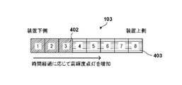
次に、図4BA-図4BCを参照して、ロック状態を解除する際の発光部125の発光態様について、説明する。図4BA-図4BCは、表示窓103から視認可能な8つのLEDを示しており、図4BA-図4BCの左側がエアロゾル生成装置100の(図1における)下側に対応し、図4BA-図4BCの右側がエアロゾル生成装置100の(図1における)上側に対応する。図4BAは、制御部120がロック状態を解除するための一連のパターンを受け付けている際の、発光部125の様子を模式的に示している。図4BAに一例として示すように、制御部120は、一連のパターンを受け付けているときには、いずれのLEDも点灯させなくてもよい(表示状態401は消灯を示す)。一連のパターンを受け付けている最中に何らLEDを発行させないようにすることで、誤操作や意図しない接触により操作部に対する入力が入った場合に、都度LEDを表示させてバッテリ残量を不必要に低下させることを防止することができる。
Next, with reference to FIGS. 4BA to 4BC, the light emitting mode of the light emitting section 125 when releasing the locked state will be described. 4BA-4BC show the eight LEDs visible through the display window 103, with the left side of FIGS. 4BA-4BC corresponding to the bottom side (in FIG. 1) of the aerosol generating device 100, The right side of 4BC corresponds to the top side (in FIG. 1) of the aerosol generator 100. FIG. FIG. 4BA schematically shows the state of the light emitting unit 125 when the control unit 120 receives a series of patterns for releasing the locked state. As shown in FIG. 4BA as an example, the control unit 120 does not have to turn on any LEDs when receiving a series of patterns (display state 401 indicates off). By not issuing any LED while accepting a series of patterns, when an input to the operation unit is entered due to an erroneous operation or unintended contact, the LED is displayed each time to reduce the remaining battery power unnecessarily. can be prevented from deteriorating.
なお、後述するように、制御部120は、エアロゾル生成装置100の動作状態が、加熱部130の加熱を開始することができない所定の状態(加熱制御状態、充電状態、及びペアリング実行用状態)である場合には、ロック状態を解除しない(或いはパターンを受け付けない)ように制御する。
As will be described later, the control unit 120 sets the operating state of the aerosol generating device 100 to a predetermined state (heating control state, charging state, and pairing execution state) in which heating of the heating unit 130 cannot be started. , control is performed not to release the locked state (or not to accept the pattern).
図4BBは、入力操作が、予め定められた一連のパターンであった場合(つまり登録したパターンと合致した場合)における発光部125の様子を示している。制御部120は、入力操作が、予め定められた一連のパターンであった場合、全てのLEDをベースライン点灯させる(表示状態403はベースライン点灯を示す)。ベースライン点灯は、LEDの最大輝度の例えば5%の輝度でLEDを点灯させることであってよい。そのうえで、LED1からLED8まで順に通常点灯の輝度(表示状態402は通常点灯)に変更してゆく。例えば、制御部120は、入力操作が予め定められた一連のパターンであると判定した時点から、例えば560msの時間のあいだに、上記8つのLEDの発光を1つずつ制御する。最終的に、発光部125は、図4BCに示すように、全てのLEDが表示状態402となる。更に、制御部120は、入力操作が予め定められた一連のパターンであると判定した時点から、例えば560msのあいだ、バイブレーションを振動させてもよい。このようにすることで、ロック状態が解除されることを視覚及び触覚を通じてユーザに報知することができる。また、表示状態をベースライン点灯にしてから順に通常点灯にすることで、視覚的な変化を強調し、よりユーザの目にとまり易い報知を行うことができる。
FIG. 4BB shows the state of the light emitting unit 125 when the input operation is a series of predetermined patterns (that is, when it matches the registered pattern). When the input operation is a series of predetermined patterns, the control unit 120 causes all the LEDs to be baseline lit (the display state 403 indicates baseline lighting). Baseline lighting may be lighting the LED at a luminance of, for example, 5% of the maximum luminance of the LED. After that, the luminance of LED1 to LED8 is changed to normal lighting (the display state 402 is normal lighting). For example, the control unit 120 controls the light emission of the eight LEDs one by one for a time period of, for example, 560 ms from the time when the input operation is determined to be a series of predetermined patterns. Finally, all the LEDs of the light emitting unit 125 are in the display state 402 as shown in FIG. 4BC. Furthermore, the control unit 120 may vibrate for, for example, 560 ms from the time when the input operation is determined to be a series of predetermined patterns. By doing so, the user can be notified visually and tactilely that the locked state is released. In addition, by changing the display state from the baseline lighting to the normal lighting in order, visual changes can be emphasized, and notification can be made more easily noticeable to the user.
上述の実施形態では、誤った入力操作がなされた場合については明示していないが、入力操作が一連のパターンと合致した場合の態様(図4BB)とは異なる態様でLEDを発光させてもよい。或いは、一連のパターンの入力途中と同様、バッテリ残量を維持するために、何らの表示を行わないようにしてもよい。
In the above-described embodiment, the case where an erroneous input operation is performed is not specified, but the LED may be illuminated in a manner different from the manner in which the input operation matches a series of patterns (FIG. 4BB). . Alternatively, as in the middle of inputting a series of patterns, in order to maintain the remaining battery power, no display may be performed.
エアロゾル生成装置100は、一旦ロック状態が解除された場合に、自動的に再ロックを行うことができる。例えば、制御部120は、ロック状態を解除した後、又は後述する最後の加熱制御状態の完了後から所定時間(例えば15分)の経過後に再びロック状態にしてもよい。このとき、制御部120は、ロック状態を解除した後の10分後に、加熱制御状態にて吸引が行われた場合には、加熱制御状態が終了してから所定時間(15分)後に再ロックしてよい。
The aerosol generator 100 can be automatically relocked once the locked state has been released. For example, after releasing the locked state, or after a predetermined period of time (for example, 15 minutes) has elapsed after the completion of the final heating control state described later, the control unit 120 may return to the locked state. At this time, if suction is performed in the heating control state 10 minutes after releasing the locking state, the control unit 120 relocks after a predetermined time (15 minutes) after the heating control state ends. You can
<エアロゾル生成装置の動作状態の例>
エアロゾル生成装置100の状態遷移の一例について、図5を参照して説明する。エアロゾル生成装置100は、いくつかの動作状態を有し、ユーザによる入力や制御部120の制御に応じて、状態遷移を行う。エアロゾル生成装置100の動作状態は、例えば、スリープ状態501、アクティブ状態502、ペアリング実行用状態503を含む。また、エアロゾル生成装置100の動作状態は、アクティブ状態502を起点として遷移可能な1つ以上の動作状態(例えば加熱制御状態504及び加熱終了状態505)、及びスリープ状態501を起点として遷移可能な1つ以上の動作状態(例えば充電状態506)を有してよい。
<Example of operating state of aerosol generator>
An example of state transition of the aerosol generating device 100 will be described with reference to FIG. The aerosol generating device 100 has several operating states, and performs state transitions according to user input and control by the control unit 120 . The operating states of the aerosol generating device 100 include, for example, a sleep state 501, an active state 502, and a pairing execution state 503. In addition, the operating state of the aerosol generating device 100 includes one or more operating states (for example, the heating control state 504 and the heating end state 505) that can transition starting from the active state 502, and one or more operating states that can transition starting from the sleep state 501. It may have one or more operating states (eg, charging state 506).
スリープ状態501は、例えば、制御部120による動作を一時的に停止させて、消費電力を低下させた節電状態で待機させる状態である。スリープ状態が解除される際には、停止前の状態から動作を再開してよい。制御部120は、予め定められたユーザ入力を受け付けることができ、該当するユーザ入力を受け付けると、当該ユーザ入力に応じた状態(例えばアクティブ状態502或いはペアリング実行用状態503)へ状態を遷移させることができる。なお、以下の説明では、スリープ状態を待機状態という場合もある。本実施形態では、制御部120のメモリの内容を維持して待機状態に入る「サスペンド」或いは「スタンバイ」の方法によりスリープ状態501となってもよいし、制御部120のメモリの内容を記憶部121に複製して待機状態に入る「ハイバネーション」の方法によりスリープ状態となってもよい。
The sleep state 501 is, for example, a state in which the operation of the control unit 120 is temporarily stopped to wait in a power saving state in which power consumption is reduced. When the sleep state is canceled, the operation may be resumed from the state before the stop. The control unit 120 can accept a predetermined user input, and when the corresponding user input is accepted, the control unit 120 changes the state to a state corresponding to the user input (for example, the active state 502 or the pairing execution state 503). be able to. In the following description, the sleep state may also be referred to as the standby state. In the present embodiment, the sleep state 501 may be entered by a method of "suspend" or "standby" while maintaining the contents of the memory of the control unit 120, or the contents of the memory of the control unit 120 may be stored in the storage unit. 121 and enter the standby state by the method of "hibernation".
エアロゾル生成装置100のスリープ状態501では、入力操作の検知機能、及び、バッテリ残量の監視機能を除いて、他の機能が稼働しない状態であってもよい。
In the sleep state 501 of the aerosol generation device 100, functions other than the input operation detection function and the remaining battery level monitoring function may not operate.
アクティブ状態502は、例えば、デバイス(例えば、エアロゾル生成装置100)の持つ機能に制限がかけられていない状態である。例えば、エアロゾル生成装置100では、少なくとも加熱機能に対する制限がかけられていない状態となる。アクティブ状態は、消費電力を低下させた節電状態であるスリープ状態に対して、当該節電状態が解除された状態であってもよい。なお、以下の説明では、アクティブ状態を稼働状態という場合もある。
The active state 502 is, for example, a state in which the functions of the device (eg, the aerosol generator 100) are not restricted. For example, in the aerosol generator 100, at least the heating function is not restricted. The active state may be a state in which the sleep state, which is a power saving state in which power consumption is reduced, is canceled. Note that, in the following description, the active state may also be referred to as the operating state.
例えば、エアロゾル生成装置100では、アクティブ状態502においてスライダ105が閉じられると、制御部120は、動作状態をアクティブ状態502(稼働状態)からスリープ状態501(待機状態)に制御する(例えば、図5の512)。また、エアロゾル生成装置100では、スリープ状態501においてスライダ105が開けられると、制御部120は、動作状態をスリープ状態501(待機状態)からアクティブ状態502(稼働状態)に制御する(例えば、図5の511)。
For example, in the aerosol generating device 100, when the slider 105 is closed in the active state 502, the control unit 120 controls the operating state from the active state 502 (operating state) to the sleep state 501 (standby state) (for example, FIG. 5 512). Further, in the aerosol generating device 100, when the slider 105 is opened in the sleep state 501, the control unit 120 controls the operating state from the sleep state 501 (standby state) to the active state 502 (operating state) (for example, FIG. 5 511).
ペアリング実行用状態503は、通信装置200とBluetooth(登録商標)のペアリングを実行するための状態である。制御部120は、スリープ状態501において、スライダ105を閉じたまま操作部材104に対する所定の入力操作が検知された場合に、状態をペアリング実行用状態へ遷移させる(例えば、図5の513)。制御部120は、通信装置200との間でペアリング(初期設定ともいう)が成功すると、記憶部121に保持されるホワイトリストにペアリングされた機器を登録する。制御部120は、ホワイトリストへの登録が成功すると、或いは、ペアリングが失敗すると、動作状態をペアリング実行用状態503からスリープ状態501に戻す。
The pairing execution state 503 is a state for executing pairing between the communication device 200 and Bluetooth (registered trademark). In the sleep state 501, the control unit 120 shifts the state to the pairing execution state (for example, 513 in FIG. 5) when a predetermined input operation on the operation member 104 is detected while the slider 105 is closed. When pairing (also referred to as initial setting) with the communication device 200 is successful, the control unit 120 registers the paired device in the whitelist held in the storage unit 121 . When the registration to the white list is successful or when the pairing fails, the control unit 120 returns the operating state from the pairing execution state 503 to the sleep state 501 .
また、制御部120は、アクティブ状態502における所定の入力操作に応じて、加熱機能を発揮させる(例えばエアロゾルを生成する)ための加熱制御状態504などに動作状態を遷移させる(例えば、図5の515)。制御部120は、その後、アクティブ状態502に動作状態を遷移させてもよい。
Further, in response to a predetermined input operation in the active state 502, the control unit 120 transitions the operation state to a heating control state 504 for exerting a heating function (for example, generating an aerosol) (for example, the state shown in FIG. 5). 515). Control unit 120 may then transition the operating state to active state 502 .
或いは、制御部120は、接続I/F128にUSB端子が接続されたことに応じて、スリープ状態501から、エアロゾル生成装置を充電している状態(例えば、506)へ動作状態を遷移させてもよい(例えば、図5の516)。
Alternatively, the control unit 120 may cause the operating state to transition from the sleep state 501 to the state of charging the aerosol generating device (eg, 506) in response to the USB terminal being connected to the connection I/F 128. Good (eg, 516 in FIG. 5).
<ロック解除処理の一連の動作>
次に、エアロゾル生成装置100において実行される、ロック解除処理の一連の動作について、図6を参照して説明する。なお、本処理は、制御部120のプロセッサが記憶部121に記憶されるプログラムを実行することにより実現される。以下の説明では、ユーザがロック状態を解除するための、一連の入力を1つずつ入力するものとする。
<A series of operations for unlock processing>
Next, a series of operations of unlock processing executed in the aerosol generating device 100 will be described with reference to FIG. Note that this processing is realized by executing a program stored in the storage unit 121 by the processor of the control unit 120 . In the following description, it is assumed that the user inputs a series of inputs one by one to release the locked state.
S601において、制御部120は、入力検知部122及び状態検知部123を介して入力操作を検知する。S602において、制御部120は、エアロゾル生成装置100がロック状態であるかを判定する。例えば、制御部120は、ロック機能が有効化又は無効化されたときにフラグ等の所定の方法によりロック状態を示す情報を保持するようにし、保持したロック状態を示す情報に基づいて、ロック状態を判定する。制御部120は、エアロゾル生成装置100がロック状態であると判定した場合、処理をS603に進める。そうでない場合、ロック状態を解除する必要がないため、制御部120は本処理の一連の動作を終了する。この場合、制御部120は本処理の終了後に、入力操作をそのまま受け付ければよい。
In S601, the control unit 120 detects an input operation via the input detection unit 122 and the state detection unit 123. In S602, the control unit 120 determines whether the aerosol generating device 100 is in the locked state. For example, the control unit 120 holds information indicating the locked state by a predetermined method such as a flag when the lock function is enabled or disabled, and based on the held information indicating the locked state, the lock state is changed. judge. When determining that the aerosol generating device 100 is in the locked state, the control unit 120 advances the process to S603. Otherwise, the controller 120 terminates the series of operations of this process because it is not necessary to release the locked state. In this case, the control unit 120 may accept the input operation as it is after the end of this process.
S603において、制御部120は、エアロゾル生成装置100の動作状態を取得する。例えば、制御部120は、状態検知部123などの各部を介して動作状態を取得し、動作状態が変化するごとに装置の動作状態を示す情報をメモリ又は記憶部121に記憶させておいてよい。そして、制御部120は、動作状態を取得する際に、メモリ又は記憶部121に記憶させた、動作状態を示す情報を参照して、エアロゾル生成装置100が充電状態であるといった動作状態を取得するようにしてよい。
In S603, the control unit 120 acquires the operating state of the aerosol generating device 100. For example, the control unit 120 may acquire the operating state via each unit such as the state detecting unit 123, and store information indicating the operating state of the device in the memory or the storage unit 121 each time the operating state changes. . Then, when acquiring the operating state, the control unit 120 refers to the information indicating the operating state stored in the memory or the storage unit 121, and acquires the operating state that the aerosol generating device 100 is in the charging state. You can do
S604において、制御部120は、エアロゾル生成装置100の動作状態が、加熱部130の加熱を開始できない状態かを判定する。例えば、制御部120は、エアロゾル生成装置100の動作状態がペアリング実行用状態(すなわち近距離無線通信の初期設定を行っている状態)であるかを判定する。制御部120は、エアロゾル生成装置100の動作状態がペアリング実行用状態である場合には、加熱部130の加熱を開始できない状態であると判定して、本一連の動作を終了し、そうでない場合には、処理をS605に進める。
In S604, the control unit 120 determines whether the operating state of the aerosol generating device 100 is such that the heating unit 130 cannot start heating. For example, the control unit 120 determines whether the operating state of the aerosol generating device 100 is a state for performing pairing (that is, a state in which initial settings for short-range wireless communication are being performed). When the operating state of the aerosol generating device 100 is the pairing execution state, the control unit 120 determines that the heating of the heating unit 130 cannot be started, ends this series of operations, and otherwise ends the operation. If so, the process proceeds to S605.
或いは、制御部120は、エアロゾル生成装置100の動作状態が充電状態であるかを判定する。制御部120は、エアロゾル生成装置100の動作状態が充電状態である場合には、加熱部130の加熱を開始できない状態であると判定して、本一連の動作を終了し、そうでない場合には、処理をS605に進めてもよい。
Alternatively, the control unit 120 determines whether the operating state of the aerosol generating device 100 is the charging state. When the operating state of the aerosol generating device 100 is the charging state, the control unit 120 determines that the heating unit 130 cannot start heating, and terminates this series of operations. , the process may proceed to S605.
或いは、制御部120は、エアロゾル生成装置100の動作状態が加熱制御状態であるかを判定する。制御部120は、エアロゾル生成装置100の動作状態が加熱制御状態である場合には、加熱部130の加熱を開始できない状態であると判定して、本一連の動作を終了し、そうでない場合には、処理をS605に進めてもよい。
Alternatively, the control unit 120 determines whether the operating state of the aerosol generating device 100 is the heating control state. When the operating state of the aerosol generating device 100 is the heating control state, the control unit 120 determines that the heating of the heating unit 130 cannot be started, terminates this series of operations, and otherwise may advance the process to S605.
或いは、制御部120は、前面パネル102が外れていないかを判定し、前面パネル102が外れている場合に、加熱部130の加熱を開始できない状態と判定して本一連の動作を終了し、そうでない場合には処理をS605に進めてもよい。前面パネルの着脱を考慮することにより、エアロゾル生成装置100が適切な状態で使用されている場合にのみロックを解除して、その後、加熱部130を加熱可能にすることができる。
Alternatively, the control unit 120 determines whether the front panel 102 is removed, and if the front panel 102 is removed, determines that the heating unit 130 cannot start heating, and terminates this series of operations, Otherwise, the process may proceed to S605. By considering the attachment and detachment of the front panel, the lock can be released only when the aerosol generating device 100 is being used in an appropriate state, and then the heating unit 130 can be heated.
また、制御部120は、残量計133からの信号に基づき、バッテリ残量が所定の閾値未満であるかを判定してもよい。すなわち、制御部120は、バッテリ残量が所定の閾値未満である場合に、加熱部130の加熱を開始できない状態と判定してもよい。このようにバッテリ残量を考慮することにより、ユーザがエアロゾルの吸引を始めようとした際に電力不足になるようなユーザ体験の低下を防止することができる。
Also, the control unit 120 may determine whether the remaining battery level is less than a predetermined threshold value based on the signal from the remaining battery level gauge 133 . That is, the control unit 120 may determine that the heating unit 130 cannot start heating when the remaining battery charge is less than a predetermined threshold. Considering the remaining battery capacity in this way can prevent a deterioration in the user experience such as running out of power when the user starts to inhale the aerosol.
なお、操作部に対する入力操作が開始された後であり、且つ当該入力操作がユーザによって定められた一連のパターンを構成する前に、動作状態が加熱を開始できない状態となった場合、制御部120は、動作状態が加熱を開始できない状態となった後の入力操作を受け付けない。このとき、制御部120は、動作状態が加熱を開始することができない状態となる前に受け付けた入力操作を破棄する。
It should be noted that if the operation state becomes a state in which heating cannot be started after the input operation to the operation unit is started and before the input operation constitutes a series of patterns determined by the user, the control unit 120 does not accept an input operation after the operating state becomes a state in which heating cannot be started. At this time, control unit 120 discards the input operation received before the operating state becomes a state in which heating cannot be started.
S605において、制御部120は、操作部に対する入力操作を受け付ける。このように、制御部120は、S604を先に実行して、加熱を開始することができない状態では入力操作を受け付けないようにすることで、ロックを解除しても吸引することができない状況の発生を防止することができる。制御部120は、受け付けた入力操作を、例えば制御部120のメモリに一時的に記憶させる。この場合、メモリには、これまで受け付けた一連の入力操作が記憶される。
At S605, the control unit 120 accepts an input operation to the operation unit. In this way, the control unit 120 executes S604 first and does not accept an input operation in a state in which heating cannot be started. occurrence can be prevented. The control unit 120 temporarily stores the received input operation in the memory of the control unit 120, for example. In this case, the memory stores a series of input operations that have been accepted so far.
S606において、制御部120は、受け付けた入力操作の数が、ロック解除用に設定されている一連のパターンの操作数以上となったかを判定する。制御部120は、例えば、受け付けた入力操作の数(例えば、6つ)と、ロック解除用に設定されている一連のパターンの操作数(例えば、予め設定された「5回短押し+1回長押し」)とを比較する。制御部120は、受け付けた入力操作の数が、ロック解除用に設定されている一連のパターンの操作数以上であると判定した場合、処理をS607に進める。そうでない場合(すなわち、入力操作数がロック解除設定の操作数に満たない)、制御部120は、更に入力を受け付けるために、処理をS601に戻す。
In S606, the control unit 120 determines whether the number of received input operations is greater than or equal to the number of operations in a series of patterns set for unlocking. For example, the control unit 120 controls the number of received input operations (for example, 6) and the number of operations in a series of patterns set for unlocking (for example, a preset "5 short presses + 1 long press"). push"). If the control unit 120 determines that the number of received input operations is equal to or greater than the number of operations of the series of patterns set for unlocking, the process proceeds to S607. Otherwise (that is, the number of input operations is less than the number of lock release setting operations), the control unit 120 returns the process to S601 in order to receive further input.
S607において、制御部120は、入力操作が所定の一連のパターンを構成するかを判定する。例えば、制御部120は、メモリに記憶されている、これまで受け付けた一連の入力操作(例えば「5回短押し+1回長押し」)と、ロック解除用に設定されている一連のパターンの操作数(例えば、予め設定された「5回短押し+1回長押し」)とを比較する。両者が一致した場合、制御部120は、入力操作が所定の一連のパターンを構成したと判定して、処理をS608に進める。そうでない場合、制御部120は、受け付けた入力操作が解除パターンと一致しない(正しい入力ではない)と判定して、本一連の処理を終了する。
In S607, the control unit 120 determines whether the input operation constitutes a series of predetermined patterns. For example, the control unit 120 can perform a series of input operations (for example, “5 short presses + 1 long press”) stored in the memory and a series of operation patterns set for unlocking. The number (for example, "5 short presses + 1 long press" set in advance) is compared. If both match, the control unit 120 determines that the input operation forms a predetermined series of patterns, and advances the process to S608. Otherwise, control unit 120 determines that the received input operation does not match the release pattern (is not correct input), and terminates this series of processes.
S608において、制御部120は、エアロゾル生成装置100のロック状態を解除する。そして、S609において、例えば図4Bを参照して説明したように、LEDを点灯するとともに、バイブレーションを駆動する。制御部120は、S609におけるLEDの点灯及びバイブレーションの駆動が完了すると、本一連の処理を完了する。
In S608, the control unit 120 unlocks the aerosol generating device 100. Then, in S609, for example, as described with reference to FIG. 4B, the LED is turned on and the vibration is driven. When the lighting of the LED and the driving of the vibration in S609 are completed, the control unit 120 completes this series of processing.
このように、本実施形態では、制御部120は、入力操作がユーザにより定められた(設定された)一連のパターンを構成すると判定したことに応じて、エアロゾル生成装置に対するロック状態を解除するようにした。このとき、エアロゾル生成装置の動作状態が加熱部130の加熱を開始することができない(S604で上述した)状態である場合には、ロック状態を解除しないようにした。このようにすることで、適切なタイミングでエアロゾル生成装置に対するロックを解除することが可能になる。
As described above, in the present embodiment, the control unit 120 cancels the locked state of the aerosol generation device in response to determining that the input operation constitutes a series of patterns defined (set) by the user. made it At this time, if the operating state of the aerosol generating device is such that the heating of the heating unit 130 cannot be started (described above in S604), the locked state is not released. By doing so, it becomes possible to unlock the aerosol generator at an appropriate timing.
<ロック解除処理の他の例>
次に、エアロゾル生成装置100において実行される、ロック解除処理の他の例について、図7A及び図7Bを参照して説明する。本処理では、図6を参照して上述したロック解除処理の動作に加えて、他の機能に割り当てられている予め定められた操作(既定操作という)を優先的に受け付ける。なお、本処理は、制御部120のプロセッサが記憶部121に記憶されるプログラムを実行することにより実現される。以下の説明では、図6と同一又は実質的に同一である動作については同一の参照符号を付して重複する説明は省略する。
<Another example of unlock processing>
Next, another example of unlocking processing executed in the aerosol generating device 100 will be described with reference to FIGS. 7A and 7B. In this process, in addition to the operation of the unlocking process described above with reference to FIG. 6, a predetermined operation (referred to as default operation) assigned to another function is preferentially accepted. Note that this processing is realized by executing a program stored in the storage unit 121 by the processor of the control unit 120 . In the following description, operations that are the same or substantially the same as those in FIG. 6 are denoted by the same reference numerals, and overlapping descriptions are omitted.
制御部120は、S601及びS602の処理を、上述した図6の動作と同様に実行し、エアロゾル生成装置100がロック状態である場合、S701に処理を進める。エアロゾル生成装置100がロック状態でない場合、ロック状態を解除する必要がないため、制御部120は本処理の一連の動作を終了する。この場合、制御部120は本処理の終了後に、入力操作をそのまま受け付ければよい。
The control unit 120 executes the processing of S601 and S602 in the same manner as the operation of FIG. 6 described above, and advances the processing to S701 when the aerosol generating device 100 is in the locked state. If the aerosol generating device 100 is not in the locked state, it is not necessary to release the locked state, so the control unit 120 terminates the series of operations of this process. In this case, the control unit 120 may accept the input operation as it is after the end of this process.
S701において、制御部120は、入力操作が既定操作に対応するものであるかを判定する。既定操作は、例えば、Bluetooth(登録商標)のペアリングを実行するための、予め定められた操作(例えば、操作部に対する3回の短押しと1回の長押し)であるものとする。制御部120は、これまでの入力操作が既定操作を構成する一連のパターンに対応する(例えば、これまでの入力操作が2回の短押しである)場合、既定操作に割り当てられた機能を実行できるようにするため、(S603及びS604の判定を行わずに)S605において入力を受け付ける。換言すれば、制御部120は、入力操作が、既定操作の一連のパターンに対応する場合、ユーザにより定められたロック解除用の一連のパターンよりも優先して、既定操作に割り当てられた機能を実行することができる。
In S701, the control unit 120 determines whether the input operation corresponds to the default operation. The default operation is, for example, a predetermined operation (for example, three short presses and one long press on the operation unit) for executing Bluetooth (registered trademark) pairing. If the input operation so far corresponds to a series of patterns forming the default operation (for example, the input operation so far is two short presses), the control unit 120 executes the function assigned to the default operation. To do so, an input is accepted at S605 (without making the determinations of S603 and S604). In other words, when the input operation corresponds to a series of default operation patterns, control unit 120 prioritizes the function assigned to the default operation over the unlock pattern set by the user. can be executed.
S702において、制御部120は、受け付けた入力操作が既定操作の一連のパターンを構成するかを判定する。制御部120は、受け付けた入力操作が既定操作の一連のパターン(例えば、ペアリングのための3回の短押しと1回の長押し)を構成する場合、ロック状態を解除して優先的にペアリングを実行するために、S608に処理を進める。制御部120は、受け付けた入力操作が既定操作の一連のパターンを構成しない場合、図6に示したS606及びS607の処理(ロック解除の処理)を実行する。制御部120は、その後、S608及びS609の処理を上述と同様に実行して、本一連の処理を終了する。
In S702, the control unit 120 determines whether the received input operation constitutes a series of patterns of default operations. When the received input operation constitutes a series of predetermined operation patterns (for example, three short presses and one long press for pairing), the control unit 120 cancels the lock state and preferentially To execute pairing, the process proceeds to S608. If the received input operation does not constitute a series of default operation patterns, the control unit 120 executes the processes of S606 and S607 shown in FIG. 6 (unlock process). After that, the control unit 120 executes the processes of S608 and S609 in the same manner as described above, and ends this series of processes.
このようにすることで、エアロゾル生成装置100に既定操作が登録されている場合には、既定操作を優先して実行することができる。そして、既定操作を優先しながら、エアロゾル生成装置の動作状態が加熱部130の加熱を開始することができない(S604で上述した)状態である場合には、ロック状態を解除しないようにすることができる。すなわち、適切なタイミングでエアロゾル生成装置に対するロックを解除することができる。
By doing so, when a default operation is registered in the aerosol generating device 100, the default operation can be preferentially executed. Then, while giving priority to the predetermined operation, if the operating state of the aerosol generating device is a state in which the heating of the heating unit 130 cannot be started (described above in S604), the locked state can be prevented from being released. can. That is, it is possible to unlock the aerosol generator at an appropriate timing.
なお、上述の実施形態では、操作部材104が物理的なボタンである場合を例に説明した。しかし、操作部材104は前面パネル102から露出したタッチパネルであってもよい。この場合、入力操作は、タッチパネルに対するタップ操作と、タッチパネルの面に沿うフリック操作とを含んでよい。ユーザは、タッチパネルに対するタップ操作と、タッチパネル上のフリック操作とを組み合わせて、ロック解除用の一連のパターンを構成してもよい。
In addition, in the above-described embodiment, the case where the operation member 104 is a physical button has been described as an example. However, the operation member 104 may be a touch panel exposed from the front panel 102 . In this case, the input operation may include a tap operation on the touch panel and a flick operation along the surface of the touch panel. The user may configure a series of patterns for unlocking by combining a tap operation on the touch panel and a flick operation on the touch panel.
また、上述のロック解除処理では、制御部120が入力操作を受け付けてロック状態を解除する場合を例に説明した。しかし、上述の実施形態は、ロック状態を解除するために、ペアリングされた通信装置からBluetooth(登録商標)を介して送信される、ロック状態を解除する信号を受信する場合に適用することができる。すなわち、制御部120は、ペアリングされた通信装置からロック状態を解除する信号を受信したことに応じて、エアロゾル生成装置100に対するロック状態を解除するようにしてもよい。このとき、制御部120は、エアロゾル生成装置100の動作状態が加熱部130の加熱を開始することができない(上述の)所定の状態である場合には、ロック状態を解除しないように構成される。このようにしても、適切なタイミングでエアロゾル生成装置に対するロックを解除することができる。
Also, in the unlocking process described above, the case where the control unit 120 accepts an input operation and unlocks the locked state has been described as an example. However, the above-described embodiments can be applied when receiving a signal to release the locked state transmitted via Bluetooth from a paired communication device in order to release the locked state. can. That is, the control unit 120 may unlock the aerosol generating device 100 in response to receiving a signal for unlocking from the paired communication device. At this time, the control unit 120 is configured not to unlock the locked state when the operating state of the aerosol generating device 100 is the predetermined state (described above) in which the heating of the heating unit 130 cannot be started. . Also in this way, the aerosol generator can be unlocked at an appropriate timing.
発明は上記の実施形態に制限されるものではなく、発明の要旨の範囲内で、種々の変形・変更が可能である。
The invention is not limited to the above embodiments, and various modifications and changes are possible within the scope of the invention.
本願は、2021年4月28日提出の日本国特許出願特願2021-076013を基礎として優先権を主張するものであり、その記載内容の全てを、ここに援用する。
This application claims priority based on Japanese Patent Application No. 2021-076013 filed on April 28, 2021, and the entire contents thereof are incorporated herein.