WO2022228923A1 - Method for determining the torque of an electric machine - Google Patents
Method for determining the torque of an electric machine Download PDFInfo
- Publication number
- WO2022228923A1 WO2022228923A1 PCT/EP2022/060190 EP2022060190W WO2022228923A1 WO 2022228923 A1 WO2022228923 A1 WO 2022228923A1 EP 2022060190 W EP2022060190 W EP 2022060190W WO 2022228923 A1 WO2022228923 A1 WO 2022228923A1
- Authority
- WO
- WIPO (PCT)
- Prior art keywords
- electric machine
- magnetic flux
- torque
- determined
- current
- Prior art date
Links
- 238000000034 method Methods 0.000 title claims abstract description 66
- 230000004907 flux Effects 0.000 claims abstract description 83
- 230000005291 magnetic effect Effects 0.000 claims abstract description 73
- 238000005259 measurement Methods 0.000 claims description 37
- 239000011159 matrix material Substances 0.000 claims description 11
- 230000003044 adaptive effect Effects 0.000 claims description 10
- 230000001360 synchronised effect Effects 0.000 claims description 9
- 238000004804 winding Methods 0.000 claims description 6
- 230000001419 dependent effect Effects 0.000 claims description 4
- 230000006870 function Effects 0.000 description 24
- 238000010276 construction Methods 0.000 description 4
- 101000841267 Homo sapiens Long chain 3-hydroxyacyl-CoA dehydrogenase Proteins 0.000 description 3
- 102100029107 Long chain 3-hydroxyacyl-CoA dehydrogenase Human genes 0.000 description 3
- JJYKJUXBWFATTE-UHFFFAOYSA-N mosher's acid Chemical compound COC(C(O)=O)(C(F)(F)F)C1=CC=CC=C1 JJYKJUXBWFATTE-UHFFFAOYSA-N 0.000 description 3
- 238000011217 control strategy Methods 0.000 description 2
- 238000012937 correction Methods 0.000 description 2
- 238000013461 design Methods 0.000 description 2
- 238000003745 diagnosis Methods 0.000 description 2
- 238000005516 engineering process Methods 0.000 description 2
- 239000003205 fragrance Substances 0.000 description 2
- 238000012544 monitoring process Methods 0.000 description 2
- 238000012360 testing method Methods 0.000 description 2
- 230000006978 adaptation Effects 0.000 description 1
- 238000013459 approach Methods 0.000 description 1
- 238000004364 calculation method Methods 0.000 description 1
- 230000008859 change Effects 0.000 description 1
- 230000000052 comparative effect Effects 0.000 description 1
- 230000008878 coupling Effects 0.000 description 1
- 238000010168 coupling process Methods 0.000 description 1
- 238000005859 coupling reaction Methods 0.000 description 1
- 238000001514 detection method Methods 0.000 description 1
- 238000001914 filtration Methods 0.000 description 1
- 230000010354 integration Effects 0.000 description 1
- 230000010363 phase shift Effects 0.000 description 1
- 238000010248 power generation Methods 0.000 description 1
- 230000008569 process Effects 0.000 description 1
- 230000009466 transformation Effects 0.000 description 1
- 238000010200 validation analysis Methods 0.000 description 1
Classifications
-
- H—ELECTRICITY
- H02—GENERATION; CONVERSION OR DISTRIBUTION OF ELECTRIC POWER
- H02P—CONTROL OR REGULATION OF ELECTRIC MOTORS, ELECTRIC GENERATORS OR DYNAMO-ELECTRIC CONVERTERS; CONTROLLING TRANSFORMERS, REACTORS OR CHOKE COILS
- H02P21/00—Arrangements or methods for the control of electric machines by vector control, e.g. by control of field orientation
- H02P21/13—Observer control, e.g. using Luenberger observers or Kalman filters
-
- H—ELECTRICITY
- H02—GENERATION; CONVERSION OR DISTRIBUTION OF ELECTRIC POWER
- H02P—CONTROL OR REGULATION OF ELECTRIC MOTORS, ELECTRIC GENERATORS OR DYNAMO-ELECTRIC CONVERTERS; CONTROLLING TRANSFORMERS, REACTORS OR CHOKE COILS
- H02P21/00—Arrangements or methods for the control of electric machines by vector control, e.g. by control of field orientation
- H02P21/14—Estimation or adaptation of machine parameters, e.g. flux, current or voltage
- H02P21/141—Flux estimation
-
- H—ELECTRICITY
- H02—GENERATION; CONVERSION OR DISTRIBUTION OF ELECTRIC POWER
- H02P—CONTROL OR REGULATION OF ELECTRIC MOTORS, ELECTRIC GENERATORS OR DYNAMO-ELECTRIC CONVERTERS; CONTROLLING TRANSFORMERS, REACTORS OR CHOKE COILS
- H02P21/00—Arrangements or methods for the control of electric machines by vector control, e.g. by control of field orientation
- H02P21/14—Estimation or adaptation of machine parameters, e.g. flux, current or voltage
- H02P21/20—Estimation of torque
-
- H—ELECTRICITY
- H02—GENERATION; CONVERSION OR DISTRIBUTION OF ELECTRIC POWER
- H02P—CONTROL OR REGULATION OF ELECTRIC MOTORS, ELECTRIC GENERATORS OR DYNAMO-ELECTRIC CONVERTERS; CONTROLLING TRANSFORMERS, REACTORS OR CHOKE COILS
- H02P23/00—Arrangements or methods for the control of AC motors characterised by a control method other than vector control
- H02P23/12—Observer control, e.g. using Luenberger observers or Kalman filters
-
- H—ELECTRICITY
- H02—GENERATION; CONVERSION OR DISTRIBUTION OF ELECTRIC POWER
- H02P—CONTROL OR REGULATION OF ELECTRIC MOTORS, ELECTRIC GENERATORS OR DYNAMO-ELECTRIC CONVERTERS; CONTROLLING TRANSFORMERS, REACTORS OR CHOKE COILS
- H02P23/00—Arrangements or methods for the control of AC motors characterised by a control method other than vector control
- H02P23/14—Estimation or adaptation of motor parameters, e.g. rotor time constant, flux, speed, current or voltage
Abstract
The present invention relates to a method for determining the torque (Te) of an electric machine, in which the currents and voltages are measured (MES), and the electrical rotation speed of the rotor of the machine is determined. Next, using a dynamic model (MOD) of the magnetic flux and an unscented Kalman filter, the flux ( Φ ) and, subsequently, the torque (Te) of the electric machine are determined.
Description
PROCEDE DE DETERMINATION DU COUPLE D’UNE MACHINE ELECTRIQUE METHOD FOR DETERMINING THE TORQUE OF AN ELECTRIC MACHINE
Domaine technique Technical area
La présente invention concerne le domaine du contrôle des machines électriques, en particulier le contrôle des machines électriques synchrones à pôles saillants. Ces machines électriques trouvent une application notamment dans le domaine des véhicules automobiles. The present invention relates to the field of the control of electrical machines, in particular the control of synchronous electrical machines with salient poles. These electrical machines find an application in particular in the field of motor vehicles.
Classiquement, une machine électrique comprend un rotor (partie mobile) et un stator (partie fixe). Le rotor est habituellement logé à l'intérieur du stator. Généralement, le stator est de forme annulaire et est logé à l'intérieur d'un support tubulaire pour y être fixé. Conventionally, an electric machine comprises a rotor (moving part) and a stator (fixed part). The rotor is usually housed inside the stator. Generally, the stator is of annular shape and is housed inside a tubular support to be fixed there.
Le stator comprend des générateurs de flux magnétique, généralement des bobinages électriques. Ces bobinages sont alimentés par une pluralité (classiquement trois) phases électriques, afin de générer un champ magnétique tournant. De plus, selon le type de machine électrique, notamment pour les machines électriques synchrones à pôles saillants, le rotor peut comprendre des aimants permanents. The stator includes magnetic flux generators, usually electric windings. These windings are powered by a plurality (typically three) electrical phases, in order to generate a rotating magnetic field. In addition, depending on the type of electric machine, in particular for synchronous electric machines with salient poles, the rotor may comprise permanent magnets.
Lors du fonctionnement d'une telle machine électrique, les bobinages du stator sont parcourus par un courant électrique pour générer le champ magnétique nécessaire à l'entraînement en rotation du rotor. During the operation of such an electric machine, the windings of the stator are traversed by an electric current to generate the magnetic field necessary for driving the rotor in rotation.
Dans le domaine de machines électriques, la machine synchro-réluctante assistée d’aimants permanents est aujourd’hui de plus en plus développée dans de nombreuses applications industrielles en raison de son facteur de puissance, de son efficacité, de sa compacité et de sa capacité à fonctionner à haute vitesse. Grâce à l’aimant permanent dans la construction du rotor, le facteur de puissance est amélioré et les pertes du stator sont considérablement réduites par rapport aux machines synchro-réluctantes. De plus, le couple de réluctance créé dans une telle machine limite le besoin en aimant permanent, qui reste encore onéreux, et rend donc ce type de machine moins chère à produire. In the field of electrical machines, the synchro-reluctant machine assisted by permanent magnets is today more and more developed in many industrial applications because of its power factor, its efficiency, its compactness and its capacity. to operate at high speed. Thanks to the permanent magnet in the construction of the rotor, the power factor is improved and the losses of the stator are considerably reduced compared to synchro-reluctant machines. In addition, the reluctance torque created in such a machine limits the need for a permanent magnet, which is still expensive, and therefore makes this type of machine less expensive to produce.
Dans plusieurs applications industrielles, l’information précise du couple est indispensable pour les machines électrique que ce soit pour le contrôle du couple, notamment avec les stratégies MTPA ou MTPV (respectivement de l’anglais « Maximum Torque per Ampere » pouvant être traduit par couple maximum par ampère, et « Maximum Torque per Voltage » pouvant être traduit par couple maximum par volt), pour la validation au banc moteur, pour le diagnostic et la détection des fautes, et aussi pour la surveillance et la sécurité. In several industrial applications, precise torque information is essential for electrical machines, whether for torque control, in particular with MTPA or MTPV strategies (respectively from the English "Maximum Torque per Ampere" which can be translated by torque maximum per ampere, and “Maximum Torque per Voltage” which can be translated as maximum torque per volt), for validation on the engine bench, for diagnosis and fault detection, and also for monitoring and safety.
Technique antérieure
Les informations de couple peuvent être obtenues au moyen de mesures par des capteurs de couples, mais ces capteurs sont souvent coûteux, contiennent beaucoup de bruit, et sont difficilement utilisables en temps réel. Le document « P. Sue, D. Wilson, L. Farr, and A. Kretschmar, “High précision torque measurement on a rotating load coupling for power génération operations,” in 2012 IEEE International Instrumentation and Measurement Technology Conférence Proceedings. IEEE, 2012, pp. 518-523. » décrit une telle détermination du couple au moyen d’un capteur. Prior technique The torque information can be obtained by means of measurements by torque sensors, but these sensors are often expensive, contain a lot of noise, and are difficult to use in real time. The document “P. Sue, D. Wilson, L. Farr, and A. Kretschmar, “High precision torque measurement on a rotating load coupling for power generation operations,” in 2012 IEEE International Instrumentation and Measurement Technology Conference Proceedings. IEEE, 2012, p. 518-523. describes such a torque determination by means of a sensor.
Une autre possibilité pour déterminer le couple d’une machine électrique consiste en l’utilisation d’algorithmes qui donnent une estimation du couple à partir d’autres mesures telles que les courants, les tensions et la vitesse de rotation du rotor de la machine électrique. Par exemple, le document « K. C. Yeo, G. Heins, and F. De Boer, “Comparison of torque estimators for pmsm,” in 2008 Australasian Universities Power Engineering Conférence. IEEE, 2008, pp. 1-6. » décrit une estimation du couple au moyen d’une équation générale de couple, en supposant que les inductances et le flux d’aimant permanent sont tous connus et constants. Cette approche est simple à appliquer, mais son manque de robustesse est un inconvénient majeur en raison de son hypothèse non réaliste (inductance et flux magnétiques connus et constants). Another possibility to determine the torque of an electric machine consists in the use of algorithms which give an estimate of the torque from other measurements such as the currents, the voltages and the speed of rotation of the rotor of the electric machine. . For example, the paper “K. C. Yeo, G. Heins, and F. De Boer, “Comparison of torque estimators for pmsm,” in 2008 Australasian Universities Power Engineering Conference. IEEE, 2008, p. 1-6. describes an estimate of torque using a general torque equation, assuming the inductances and permanent magnet flux are all known and constant. This approach is simple to apply, but its lack of robustness is a major drawback due to its unrealistic assumption (known and constant inductance and magnetic fluxes).
Une autre solution décrite dans le document « J. Xu, S. Panda, Y. Pan, T. Lee, and B. Lam, “Improved pmsm pulsating torque minimization with itérative learning and sliding mode observer,” in 2000 26th Annual Conférence of the IEEE Industrial Electronics Society. IECON 2000. 2000 IEEE International Conférence on Industrial Electronics, Control and Instrumentation. 21 st Century Technologies, vol. 3. IEEE, 2000, pp. 1931-1936. » concerne une technique de mode glissant pour faire l’estimation du couple. Toutefois, cette méthode ne concerne que les machines électriques non saillantes, et les inductances de la machine électrique doivent être connues avec précision a priori, ce qui n’est pas toujours facile en pratique. Another solution described in the document “J. Xu, S. Panda, Y. Pan, T. Lee, and B. Lam, “Improved pmsm pulsating torque minimization with iterative learning and sliding mode observer,” in 2000 26th Annual Conference of the IEEE Industrial Electronics Society. IECON 2000. 2000 IEEE International Conference on Industrial Electronics, Control and Instrumentation. 21st Century Technologies, vol. 3. IEEE, 2000, p. 1931-1936. is about a sliding mode technique for estimating torque. However, this method only concerns non-salient electric machines, and the inductances of the electric machine must be known with precision a priori, which is not always easy in practice.
L’utilisation d’un observateur de flux permet également la détermination du flux. Le document « M. Koteich, “Flux estimation algorithms for electric drives: a comparative study,” in 20163rd International Conférence on Renewable Energies for Developing Countries (REDEC). IEEE, 2016, pp. 1-6. » illustre cette méthode. Un certain nombre d’observateurs de flux sont principalement développés à partir d’un modèle de tension qui comprend l’intégration de signaux de force électromotrice et l’estimation de flux à travers le modèle de courants. En général, la force électromotrice intégrée est traitée par un filtre passe-haut, alors que l’estimation du flux passe à travers un filtre passe-bas. La bonne qualité de l’estimation du flux dépend du choix de la fréquence de coupure, en particulier pour les faibles vitesses de rotation
de la machine électrique. Toutefois, un filtre qui peut rapidement atténuer le décalage constant pour des vitesses moyennes et élevées peut être imprécis à faible vitesse et inversement. En outre, la plupart des observateurs du flux en général ont besoin d’informations a priori précises sur les paramètres de la machine électrique tels que la résistance du stator, les inductances et le flux d’aimant permanent. Toutefois, ces paramètres ne sont généralement pas connus exactement dans la réalité, notamment le flux d’aimant permanent en raison du changement de température du rotor et les inductances en raison de saturation magnétique. Par conséquent, il est nécessaire de concevoir un observateur de flux qui prend en compte des incertitudes de paramètres de la machine électrique et aussi des incertitudes des mesures de capteurs. The use of a flow observer also allows the determination of the flow. The paper “M. Koteich, “Flux estimation algorithms for electric drives: a comparative study,” in 20163rd International Conference on Renewable Energies for Developing Countries (REDEC). IEEE, 2016, p. 1-6. illustrates this method. A number of flux observers are primarily developed from a voltage model that includes integration of emf signals and flux estimation through the currents model. In general, the integrated emf is processed through a high pass filter, while the flux estimate passes through a low pass filter. The good quality of the flux estimation depends on the choice of the cutoff frequency, in particular for low rotation speeds of the electric machine. However, a filter that can quickly attenuate the constant offset for medium and high speeds may be inaccurate at low speeds and vice versa. Also, most general flux observers need accurate a priori information about electrical machine parameters such as stator resistance, inductors, and permanent magnet flux. However, these parameters are usually not known exactly in reality, including permanent magnet flux due to rotor temperature change and inductances due to magnetic saturation. Consequently, it is necessary to design a flux observer which takes into account the uncertainties of the parameters of the electrical machine and also the uncertainties of the measurements of the sensors.
Résumé de l’invention Summary of the invention
L’invention a pour but de déterminer de manière précise et robuste le couple d’une machine électrique. Pour cela, la présente invention concerne un procédé de détermination du couple d’une machine électrique, dans lequel on mesure les courants et les tensions, et on détermine la vitesse de rotation électrique du rotor de la machine. Puis, au moyen d’un modèle dynamique du flux magnétique et d’un filtre de Kalman sans parfum, on détermine le flux puis le couple de la machine électrique. L’utilisation d’un filtre de Kalman sans parfum permet de prendre en compte les non linéarités du modèle dynamique du flux magnétique, assurant ainsi une efficacité et une précision de l’observateur sur toute la plage de vitesse de rotation du rotor de la machine électrique. The aim of the invention is to determine in an accurate and robust manner the torque of an electrical machine. For this, the present invention relates to a method for determining the torque of an electrical machine, in which the currents and the voltages are measured, and the electrical rotational speed of the rotor of the machine is determined. Then, using a dynamic model of magnetic flux and a fragrance-free Kalman filter, the flux and then the torque of the electrical machine are determined. The use of a fragrance-free Kalman filter makes it possible to take into account the nonlinearities of the dynamic model of the magnetic flux, thus ensuring efficiency and precision of the observer over the entire range of rotational speeds of the rotor of the machine. electric.
La présente invention concerne en outre un procédé et un système de contrôle d’une machine électrique, qui met en oeuvre le procédé de détermination du couple de la machine électrique.The present invention further relates to a method and a system for controlling an electric machine, which implements the method for determining the torque of the electric machine.
L’invention concerne un procédé de détermination du couple d’une machine électrique, ladite machine électrique comprenant un rotor, un stator, ledit stator comprenant des bobinages connectés à une pluralité de phases électriques. Pour ce procédé, on met en oeuvre les étapes suivantes : a. On mesure un courant et une tension dans lesdites phases de ladite machine électrique ; b. On détermine une vitesse de rotation électrique dudit rotor, notamment en fonction d’une vitesse de rotation mécanique dudit rotor ; c. On construit un modèle dynamique dudit flux magnétique de ladite machine électrique, ledit modèle dynamique dudit flux magnétique étant une équation différentielle dudit flux magnétique qui relie le flux magnétique au courant et à
la tension desdites phases de la machine électrique, et à la vitesse de rotation électrique dudit rotor ; d. On détermine ledit flux magnétique en appliquant un filtre de Kalman sans parfum adaptatif audit modèle dynamique dudit flux magnétique, ledit modèle dynamique de flux magnétique étant appliqué aux mesures de courant et de tension et à la vitesse de rotation électrique déterminée, et la matrice de covariance du bruit du filtre de Kalman sans parfum étant dépendante de ladite vitesse de rotation électrique du rotor ; et e. On détermine le couple de ladite machine électrique aux moyens desdites mesures de courant et au moyen dudit flux magnétique déterminé. The invention relates to a method for determining the torque of an electric machine, said electric machine comprising a rotor, a stator, said stator comprising windings connected to a plurality of electric phases. For this method, the following steps are carried out: a. A current and a voltage are measured in said phases of said electric machine; b. An electrical speed of rotation of said rotor is determined, in particular as a function of a mechanical speed of rotation of said rotor; vs. A dynamic model of said magnetic flux of said electric machine is constructed, said dynamic model of said magnetic flux being a differential equation of said magnetic flux which links the magnetic flux to the current and to the the voltage of said phases of the electrical machine, and the electrical rotational speed of said rotor; d. Said magnetic flux is determined by applying an adaptive fragrance-free Kalman filter to said dynamic model of said magnetic flux, said dynamic model of magnetic flux being applied to the current and voltage measurements and to the determined electrical rotational speed, and the covariance matrix the noise of the fragrance-free Kalman filter being dependent on said electrical speed of rotation of the rotor; summer. The torque of said electric machine is determined by means of said current measurements and by means of said determined magnetic flux.
Selon un mode de réalisation de l’invention, on détermine ladite vitesse de rotation électrique )e dudit rotor par une formule du type we=Nw avec N le nombre de paires de pôles de la machine électrique et w la vitesse de rotation mécanique dudit rotor. According to one embodiment of the invention, said electrical speed of rotation e of said rotor is determined by a formula of the type w e =Nw with N the number of pairs of poles of the electric machine and w the mechanical speed of rotation of said rotor.
Conformément à une mise en oeuvre, ledit modèle dynamique de flux magnétique s’écrit :
 avec R la résistance de la machine électrique, ooe la vitesse de rotation électrique, <pd le flux magnétique direct, <pq\e flux magnétique en quadrature, fa la dérivée par rapport au temps du flux magnétique direct, a dérivée par rapport au temps du flux magnétique en quadrature, ld le
 courant direct, lq le courant en quadrature, Vd la tension directe, Vq la tension en quadrature. Avantageusement, on détermine ledit couple de la machine électrique au moyen de la formule : avec fa le flux magnétique direct, le flux magnétique en

 quadrature, ld le courant direct, lq le courant en quadrature et N le nombre de paires de pôles de ladite machine électrique.
Selon un aspect, on applique ledit filtre de Kalman sans parfum adaptatif à l’équation d’état
quadrature, ld le courant direct, lq le courant en quadrature et N le nombre de paires de pôles de ladite machine électrique.
Selon un aspect, on applique ledit filtre de Kalman sans parfum adaptatif à l’équation d’état
 correspondant à l’état non mesurable, avec fa le flux magnétique direct, <pq\e flux magnétique
 en quadrature, correspondant à l’entrée de ladite équation d’état, avec R la résistance de la machine électrique, ld le courant direct, lq le courant en quadrature, Vd la tension directe, Vq la tension en quadrature, et
 avec ooe la vitesse de rotation électrique.According to one implementation, said dynamic magnetic flux model is written: with R the resistance of the electric machine, oo e the speed of electric rotation, <p d the direct magnetic flux, <p q \e magnetic flux in quadrature, f a the derivative with respect to time of the direct magnetic flux, a derivative with respect to the time of the magnetic flux in quadrature, l d le forward current, l q the quadrature current, V d the forward voltage, V q the quadrature voltage. Advantageously, said torque of the electric machine is determined by means of the formula: with f a the direct magnetic flux, the magnetic flux in quadrature, l d the direct current, l q the current in quadrature and N the number of pairs of poles of said electrical machine. According to one aspect, said adaptive fragrance-free Kalman filter is applied to the state equation corresponding to the non-measurable state, with f a the direct magnetic flux, <p q \e magnetic flux in quadrature, corresponding to the input of said equation of state, with R the resistance of the electric machine, l d the direct current, l q the current in quadrature, V d the direct voltage, V q the voltage in quadrature, and with oo e the electrical rotational speed.
Avantageusement, une fonction qui relie les courants et le flux magnétique est une fonction non linéaire obtenue par une méthode des éléments finis. Selon un option de réalisation, on détermine ledit flux magnétique au moyen des étapes suivantes : i. on initialise k=0, le vecteur d’état xa(0|0) = m(0) et la matrice de covariance P(0|0) = P0 ; ii. à chaque instant k différent de 0, on acquiert lesdites mesures, et on en déduit le vecteur de sortie y(k) ; et iii. à chaque instant k différent de 0, on détermine ledit flux magnétique au moyen des équations suivantes :
 avec K le gain du filtre de Kalman sans parfum adaptatif, Pxy une covariance croisée dudit état et desdites mesures, Pyy la covariance prédite des mesures, my la moyenne prédite de la sortie, ld le courant direct, lq le courant en quadrature. Conformément à une mise en oeuvre, ladite machine électrique est une machine électrique synchrone à pôles saillants, de préférence une machine synchro-réluctante assistée d’aimants permanents. Advantageously, a function which connects the currents and the magnetic flux is a nonlinear function obtained by a finite element method. According to one implementation option, said magnetic flux is determined by means of the following steps: i. we initialize k=0, the state vector x a (0|0)=m(0) and the covariance matrix P(0|0)=P 0; ii. at each instant k different from 0, said measurements are acquired, and the output vector y(k) is deduced therefrom; and iii. at each instant k different from 0, said magnetic flux is determined by means of the following equations: with K the gain of the adaptive fragrance-free Kalman filter, P xy a cross covariance of said state and said measurements, P yy the predicted covariance of the measurements, m y the predicted average of the output, l d the direct current, l q the current in quadrature. According to one implementation, said electric machine is a synchronous electric machine with salient poles, preferably a synchro-reluctant machine assisted by permanent magnets.
En outre, l’invention concerne un procédé de contrôle d’une machine électrique, pour lequel on met en oeuvre les étapes suivantes : a. On détermine le couple de ladite machine électrique au moyen du procédé de détermination dudit couple selon l’une des caractéristiques précédentes ; et b. On contrôle ladite machine électrique au moyen dudit couple déterminé.Furthermore, the invention relates to a method for controlling an electrical machine, for which the following steps are implemented: a. The torque of said electric machine is determined by means of the method for determining said torque according to one of the preceding characteristics; and B. Said electrical machine is controlled by means of said determined torque.
De plus, l’invention concerne un système de contrôle d’une machine électrique comprenant une machine électrique et un contrôleur pour mettre en oeuvre le procédé de contrôle selon l’une des caractéristiques précédentes. Furthermore, the invention relates to a system for controlling an electric machine comprising an electric machine and a controller for implementing the control method according to one of the preceding characteristics.
D'autres caractéristiques et avantages du procédé selon l'invention, apparaîtront à la lecture de la description ci-après d'exemples non limitatifs de réalisations, en se référant aux figures annexées et décrites ci-après. Other characteristics and advantages of the method according to the invention will appear on reading the following description of non-limiting examples of embodiments, with reference to the appended figures and described below.
Liste des figures List of Figures
La figure 1 illustre les étapes du procédé selon un mode de réalisation de l’invention. Figure 1 illustrates the steps of the method according to one embodiment of the invention.
La figure 2 illustre les étapes du procédé selon un deuxième mode de réalisation de l’invention.
La figure 3 illustre les courbes du courant, de la vitesse de rotation, d’angle de courant et de la tension en fonction du temps, pour un premier exemple d’application du procédé selon un mode de réalisation de l’invention. FIG. 2 illustrates the steps of the method according to a second embodiment of the invention. FIG. 3 illustrates the curves of current, speed of rotation, current angle and voltage as a function of time, for a first example of application of the method according to one embodiment of the invention.
La figure 4 illustre des courbes du couple en fonction du temps pour l’exemple de la figure 3, une première courbe correspondant au couple mesuré, et la deuxième courbe correspondant au couple déterminé par le procédé selon un mode de réalisation de l’invention. FIG. 4 illustrates curves of torque as a function of time for the example of FIG. 3, a first curve corresponding to the measured torque, and the second curve corresponding to the torque determined by the method according to one embodiment of the invention.
La figure 5 illustre les courbes de courant, de la vitesse de rotation, de déphasage de courant, et de la tension en fonction du temps, pour un deuxième exemple d’application du procédé selon un mode de réalisation de l’invention. FIG. 5 illustrates the curves of current, speed of rotation, current phase shift, and voltage as a function of time, for a second example of application of the method according to one embodiment of the invention.
La figure 6 illustre des courbes du couple en fonction du temps pour l’exemple de la figure 5, une première courbe correspondant au couple mesuré, et la deuxième courbe correspondant au couple déterminé par le procédé selon un mode de réalisation de l’invention. FIG. 6 illustrates curves of torque as a function of time for the example of FIG. 5, a first curve corresponding to the measured torque, and the second curve corresponding to the torque determined by the method according to one embodiment of the invention.
Description des modes de réalisation Description of embodiments
La présente invention concerne un procédé de détermination, en temps réel, du couple d’une machine électrique. La machine électrique comprend un rotor et un stator, ce dernier étant équipé de bobinages connectés à plusieurs phases électriques, par exemple à trois phases électriques pour générer un champ magnétique permettant la rotation du rotor. The present invention relates to a method for determining, in real time, the torque of an electrical machine. The electric machine comprises a rotor and a stator, the latter being equipped with windings connected to several electric phases, for example to three electric phases to generate a magnetic field allowing the rotation of the rotor.
Selon un aspect de l’invention, la machine électrique peut être une machine électrique synchrone à pôles saillants. En effet, le procédé est particulièrement adapté à ce type de machine, d’une part, car le modèle dynamique de la machine électrique est bien représentatif de ce type de machine électrique, et car la détermination du couple permet le contrôle d’une telle machine électrique, notamment par un contrôle direct du couple. De préférence, la machine électrique peut être une machine synchro-réluctante assistée d’aimants permanents. En effet, ce type de machine électrique nécessite une information précise de couple, notamment pour leur contrôle, par exemple au moyen d’une stratégie de contrôle de type MTPA et MTPV, pour leur diagnostic et pour leur surveillance. According to one aspect of the invention, the electrical machine may be a salient pole synchronous electrical machine. Indeed, the method is particularly suitable for this type of machine, on the one hand, because the dynamic model of the electric machine is very representative of this type of electric machine, and because the determination of the torque allows the control of such a electric machine, in particular by direct torque control. Preferably, the electric machine can be a synchro-reluctant machine assisted by permanent magnets. Indeed, this type of electrical machine requires precise torque information, in particular for their control, for example by means of a control strategy of the MTPA and MTPV type, for their diagnosis and for their monitoring.
La figure 1 décrit, schématiquement et de manière non limitative, les étapes du procédé selon un mode de réalisation de l’invention. Le procédé de détermination du flux magnétique comprend les étapes suivantes : Figure 1 describes, schematically and in a non-limiting manner, the steps of the method according to one embodiment of the invention. The magnetic flux determination method includes the following steps:
1 ) Mesures des courants et des tensions (MES) 1 ) Measurements of currents and voltages (MES)
2) Détermination de la vitesse de rotation électrique (VIT) 2) Determination of the electrical rotational speed (VIT)
3) Construction du modèle dynamique de flux magnétique (MOD)
4) Application du filtre de Kalman sans parfum adaptatif (KAL) 3) Construction of the dynamic magnetic flux model (MOD) 4) Application of Kalman filter without adaptive fragrance (KAL)
5) Détermination du couple de la machine électrique (DET) 5) Determination of the torque of the electric machine (DET)
Les étapes 1 ) à 3) sont indépendantes, et peuvent être réalisées dans cet ordre, dans un ordre différent ou simultanément. Steps 1) to 3) are independent, and can be carried out in this order, in a different order or simultaneously.
L’étape 4) permet de déterminer le flux magnétique f de la machine électrique, et l’étape 5) permet de détermine le couple Te de la machine électrique. Step 4) makes it possible to determine the magnetic flux f of the electric machine, and step 5) makes it possible to determine the torque Te of the electric machine.
Les étapes du procédé peuvent être mises en oeuvre par des moyens informatiques, notamment au moyen d’un contrôleur de la machine électrique. Ces étapes seront détaillées dans la suite de la description. The steps of the method can be implemented by computer means, in particular by means of a controller of the electrical machine. These steps will be detailed in the remainder of the description.
L’invention concerne également un procédé de contrôle d’une machine électrique. Le procédé de contrôle met en oeuvre le procédé de détermination du couple selon l’invention et une étape supplémentaire de contrôle de la machine électrique en fonction du couple déterminé. La figure 2 décrit, schématiquement et de manière non limitative, les étapes du procédé selon un deuxième mode de réalisation de l’invention. Dans ce cas, le procédé de contrôle de la machine électrique comprend les étapes suivantes : The invention also relates to a method for controlling an electrical machine. The control method implements the method for determining the torque according to the invention and an additional step of controlling the electrical machine as a function of the determined torque. Figure 2 describes, schematically and in a non-limiting manner, the steps of the method according to a second embodiment of the invention. In this case, the method for controlling the electrical machine comprises the following steps:
1 ) Mesures des courants et des tensions (MES) 1 ) Measurements of currents and voltages (MES)
2) Détermination de la vitesse de rotation électrique (VIT) 2) Determination of the electrical rotational speed (VIT)
3) Construction du modèle dynamique de flux magnétique (MOD) 3) Construction of the dynamic magnetic flux model (MOD)
4) Application du filtre de Kalman sans parfum adaptatif (KAL) 4) Application of Kalman filter without adaptive fragrance (KAL)
5) Détermination du couple de la machine électrique (DET) 5) Determination of the torque of the electric machine (DET)
6) Contrôle de la machine électrique (CTRL) 6) Electric machine control (CTRL)
Les étapes 1 ) à 3) sont indépendantes, et peuvent être réalisées dans cet ordre, dans un ordre différent ou simultanément. Steps 1) to 3) are independent, and can be carried out in this order, in a different order or simultaneously.
L’étape 4) permet de déterminer le flux magnétique f de la machine électrique, et l’étape 5) permet de détermine le couple Te de la machine électrique. Step 4) makes it possible to determine the magnetic flux f of the electric machine, and step 5) makes it possible to determine the torque Te of the electric machine.
Les étapes du procédé peuvent être mises en oeuvre par des moyens informatiques, notamment au moyen d’un contrôleur de la machine électrique. Ces étapes seront détaillées dans la suite de la description.
Dans la suite de la description, les dérivées par rapport au temps sont indiquées par un point. The steps of the method can be implemented by computer means, in particular by means of a controller of the electric machine. These steps will be detailed in the remainder of the description. In the remainder of the description, the derivatives with respect to time are indicated by a dot.
Les notations indexées par la mention
 (directe) ou (quadrature ou
 Ratings indexed by the mention (direct) or (quadrature or
« quadratique ») signifient que les grandeurs sont exprimées dans le repère de Park (repère tournant lié au rotor). En outre, les valeurs à l’état initial sont indiquées avec un 0 (t ou k = 0). “quadratic”) mean that the quantities are expressed in the Park reference (rotating reference linked to the rotor). Also, values in the initial state are indicated with a 0 (t or k = 0).
1) Mesure des courants et des tensions 1) Measurement of currents and voltages
Lors de cette étape, on mesure les courants et les tensions dans les phases de la machine électrique. During this step, the currents and voltages are measured in the phases of the electrical machine.
Ces mesures peuvent être réalisées par des capteurs de tension et de courant instrumentant la machine électrique, de manière à mesurer les courants et les tensions dans les phases de la machine électrique. These measurements can be carried out by voltage and current sensors instrumenting the electric machine, so as to measure the currents and the voltages in the phases of the electric machine.
Avantageusement, les mesures dans les phases peuvent être transformées en mesures dans le repère de Park (repère tournant lié au rotor), de manière à déterminer le courant direct, le courant en quadrature, la tension directe, et la tension en quadrature. Advantageously, the measurements in the phases can be transformed into measurements in the Park frame (rotating frame linked to the rotor), so as to determine the direct current, the current in quadrature, the direct voltage, and the voltage in quadrature.
2) Détermination de la vitesse de rotation électrique du rotor Lors de cette étape, il s’agit de déterminer la vitesse de rotation électrique du rotor. 2) Determination of the electric speed of rotation of the rotor During this stage, it is a question of determining the electric speed of rotation of the rotor.
Selon un mode de réalisation de l’invention, la vitesse de rotation électrique ooe du rotor peut être déterminée à partir de la vitesse de rotation mécanique du rotor, au moyen de la formule : wb = Nw, avec N le nombre de paires de pôles de la machine électrique et w la vitesse de rotation mécanique dudit rotor. According to one embodiment of the invention, the electrical rotation speed oo e of the rotor can be determined from the mechanical rotation speed of the rotor, by means of the formula: w b = Nw, with N the number of pairs of poles of the electric machine and w the mechanical speed of rotation of said rotor.
Conformément à une mise en oeuvre de ce mode de réalisation, la vitesse de rotation mécanique du rotor peut être estimée, par toute méthode connue de l’homme du métier. Par exemple, la vitesse de rotation mécanique peut être estimée à partir d’une méthode de type boucle à phase asservie PLL (de l’anglais « phase-locked loop »). En variante, la méthode d’estimation de la vitesse de rotation mécanique peut être conforme à celle décrite dans la demande de brevet FR 2 984 637. According to an implementation of this embodiment, the mechanical speed of rotation of the rotor can be estimated, by any method known to those skilled in the art. For example, the mechanical rotation speed can be estimated using a PLL phase-locked loop type method. As a variant, the method for estimating the mechanical rotation speed can be in accordance with that described in patent application FR 2 984 637.
Alternativement, la vitesse de rotation mécanique du rotor peut être mesurée au moyen d’un capteur de vitesse placé sur la machine électrique. Alternatively, the mechanical rotational speed of the rotor can be measured by means of a speed sensor placed on the electrical machine.
En variante, la vitesse de rotation électrique peut être déterminée directement.
3) Construction du modèle dynamique du flux magnétique Alternatively, the electrical rotational speed can be determined directly. 3) Construction of the dynamic model of the magnetic flux
Lors de cette étape, on construit un modèle dynamique du flux magnétique de la machine électrique. Le modèle dynamique du flux magnétique électrique est une équation différentielle qui relie le flux magnétique au courant et la tension des phases de la machine électrique, et à la vitesse de rotation électrique du rotor. Le modèle est dit dynamique car il est fonction de la vitesse de rotation du rotor. During this step, a dynamic model of the magnetic flux of the electric machine is constructed. The dynamic model of the electric magnetic flux is a differential equation which relates the magnetic flux to the current and the voltage of the phases of the electric machine, and to the speed of electric rotation of the rotor. The model is said to be dynamic because it is a function of the rotational speed of the rotor.
Le modèle dynamique du flux magnétique est une représentation d’état de la machine électrique. On rappelle qu’en théorie des systèmes (et en automatique), une représentation d’état permet de modéliser un système dynamique sous une forme matricielle, en utilisant des variables d’état. Cette représentation peut être linéaire ou non, continue ou discrète. La représentation permet de déterminer l’état interne et les sorties du système à n’importe quel instant futur si l’on connaît l’état à l’instant initial et le comportement des variables d’entrée qui influent sur le système. The dynamic model of the magnetic flux is a state representation of the electrical machine. We recall that in systems theory (and in automation), a state representation makes it possible to model a dynamic system in a matrix form, using state variables. This representation can be linear or not, continuous or discrete. The representation makes it possible to determine the internal state and the outputs of the system at any future instant if one knows the state at the initial instant and the behavior of the input variables which influence the system.
La dynamique du flux magnétique peut être exprimée par l’équation différentielle suivante :
 The dynamics of the magnetic flux can be expressed by the following differential equation:
Avec R la résistance de la machine électrique (pouvant être mesurée au moyen d’un capteur), )e la vitesse de rotation électrique, <pd le flux magnétique direct, <pq\e flux magnétique en quadrature, fa la dérivée par rapport au temps du flux magnétique direct, fh la dérivée par rapport au temps du flux magnétique en quadrature, ld le courant direct, lq le courant en quadrature, Vd la tension directe, Vq la tension en quadrature. With R the resistance of the electric machine (which can be measured by means of a sensor), ) e the speed of electric rotation, <p d the direct magnetic flux, <p q \e magnetic flux in quadrature, f a the derivative with respect to the time of the forward magnetic flux, f h the derivative with respect to the time of the magnetic flux in quadrature, l d the forward current, l q the current in quadrature, V d the forward voltage, V q the voltage in quadrature.
On peut réécrire cette équation sous une forme vectorielle compacte :
 ou de la manière suivante :
 avec x(t) l’état non mesurable défini par
 u(t) est l’entrée définie au moyen des mesures par
 We can rewrite this equation in compact vector form: or in the following way: with x(t) the unmeasurable state defined by u(t) is the input defined by means of the measurements by
A est la matrice dépendante de la vitesse de rotation électrique du rotor et définie par
 A is the matrix dependent on the electrical rotational speed of the rotor and defined by
Ainsi, l’équation d’état du flux peut décrite par un système linéaire variant dans le temps, Toutefois, l’équation de sortie du flux est non linéaire, étant donné que les courants dépendent du flux. Cette dépendance peut être écrite sous la forme :
 où fd et fq sont des fonctions, respectivement direct et en quadrature. Selon un mode de réalisation, les fonctions fd et fq peuvent être déterminées par une méthode des éléments finis FEMM (de l’anglais « Finite Elément Method Magnetics »). Thus, the flux state equation can be described by a linear time-varying system, however, the flux output equation is non-linear, since currents are flux dependent. This dependency can be written as: where f d and f q are functions, direct and quadrature respectively. According to one embodiment, the functions f d and f q can be determined by a finite element method FEMM (standing for “Finite Element Magnetics Method”).
Il en résulte qu’il s’agit d’un problème d’estimation non linéaire, étant donné que l’équation de sortie est non linéaire. As a result, this is a nonlinear estimation problem, since the output equation is nonlinear.
4) Application du filtre de Kalman sans parfum adaptatif 4) Application of the adaptive fragrance-free Kalman filter
Lors de cette étape, on détermine le flux magnétique de la machine électrique. Pour cela, on applique un filtre de Kalman sans parfum (UKF de l’anglais « unscented Kalman filter ») adaptatif pour le modèle construit à l’étape 3), appliqué aux mesures de tensions et de courants obtenues à l’étape 1 ), et à la vitesse de rotation électrique du rotor obtenue à l’étape 2). L’application du filtre Kalman permet d’obtenir un observateur d’état. Le filtre de Kalman sans parfum est un algorithme de filtrage qui utilise un modèle de système pour estimer l’état caché actuel d’un système, puis corrige l’estimation à l’aide des mesures de capteur disponibles. La philosophie de l’UKF diffère du filtre de Kalman étendu en ce sens qu’elle utilise la transformation sans parfum pour approcher directement la moyenne et la covariance de la distribution cible. Le filtre de Kalman sans parfum peut comporter les étapes de prédiction d’état et de correction des mesures, ces deux étapes étant précédées d’une étape préalable pour le calcul des « points sigma ». Les points sigma sont un ensemble d’échantillons calculés de manière à pouvoir propager de manière exacte les informations de moyenne et de variance dans l’espace d’une fonction non linéaire. During this step, the magnetic flux of the electric machine is determined. To do this, we apply an unscented Kalman filter (UKF for the English "unscented Kalman filter") adaptive for the model built in step 3), applied to the voltage and current measurements obtained in step 1) , and the electrical rotational speed of the rotor obtained in step 2). The application of the Kalman filter makes it possible to obtain a state observer. The Scentless Kalman Filter is a filtering algorithm that uses a system model to estimate the current hidden state of a system and then corrects the estimate using available sensor measurements. The UKF philosophy differs from the Extended Kalman Filter in that it uses the fragrance-free transformation to directly approximate the mean and covariance of the target distribution. The fragrance-free Kalman filter may comprise the stages of state prediction and measurement correction, these two stages being preceded by a preliminary stage for the calculation of the “sigma points”. Sigma points are a set of samples calculated in such a way that they can accurately propagate the mean and variance information in the space of a nonlinear function.
Selon l’invention, la matrice de covariance du bruit du filtre de Kalman sans parfum est adaptée en fonction de la vitesse de rotation électrique du rotor. Cette adaptation permet de rendre l’observateur performant (précis et robuste) sur toute la plage de vitesse de rotation de la machine électrique. According to the invention, the noise covariance matrix of the fragrance-free Kalman filter is adapted as a function of the electrical rotational speed of the rotor. This adaptation makes it possible to make the observer efficient (accurate and robust) over the entire range of rotational speeds of the electric machine.
De manière avantageuse, le modèle d’état peut s’écrire :
 Advantageously, the state model can be written:
Pour ce mode de réalisation, on peut noter :
 est l’estimation de x(k) à partir des mesures du temps k-1 . (k\k)
 est l’estimation de x(k) à partir des mesures du temps k.
 est la variance d’erreur à partir des mesures du temps k-1.
 est la variance d’erreur à partir des mesures du temps k. For this embodiment, we can note: is the estimate of x(k) from the measurements of time k-1 . (k\k) is the estimate of x(k) from the measurements of time k. is the error variance from the k-1 time measurements. is the error variance from the measurements of time k.
Conformément à une mise en oeuvre de l’invention, on peut déterminer le flux magnétique de la machine électrique au moyen des étapes suivantes : i) on initialise k=0, le vecteur d’état xa(0|0)=m(0) et l’état de la matrice de covariance,In accordance with one implementation of the invention, the magnetic flux of the electric machine can be determined by means of the following steps: i) initializing k=0, the state vector x a (0|0)=m( 0) and the state of the covariance matrix,
P(0|0) = Po ; ii) à chaque instant k, on acquiert les mesures u(k) de la machine électrique ; et iii) à chaque instant k, on détermine le flux magnétique au moyen des étapes détaillées ci-dessous. Pour l’estimation d’état donnée
 et l’estimation de la variance d’erreur donnée
 il y a deux étapes dans l’application du filtre de Kalman sans parfum : i) prédiction et ii) correction. P( 0 |0) = Po; ii) at each instant k, the measurements u(k) of the electrical machine are acquired; and iii) at each instant k, the magnetic flux is determined using the steps detailed below. For the given state estimate and the given error variance estimate there are two steps in the application of the fragrance-free Kalman filter: i) prediction and ii) correction.
On note Q(oo) la variance de bruit du système, qui dépend de la vitesse de rotation du rotor de la machine électrique. A l’instant k, pour l’étape de prédiction, on peut écrire :
 We note Q(oo) the noise variance of the system, which depends on the rotational speed of the rotor of the electric machine. At time k, for the prediction step, we can write:
Après l’étape de prédiction, la distribution de x(k) peut être donnée comme une distribution gaussienne pouvant s’écrire :
 After the prediction step, the distribution of x(k) can be given as a Gaussian distribution which can be written:
Avec
 With
With
Les points sigma associés à la moyenne mx et à la matrice Px peuvent être calculés comme suit :
 The sigma points associated with the mean m x and the matrix P x can be calculated as follows:
Avec n=2, et Si est une racine carrée de Px. Les points sigma se propagent dans le modèle de mesure sous la forme suivante, pour tout i compris entre 0 et 2n :
 les fonctions fd et fq pouvant être celles déterminées par une méthode des éléments finis FEMM. L’étape suivante peut consister à calculer la moyenne prédite my, la covariance prédite de la mesure Pyy et la covariance croisée de l’état de mesure Pxy de la manière suivante :
 avec W™ et W les poids de la moyenne prédite et de la covariance prédite, et Rnla matrice de covariance du bruit de mesure. With n=2, and Si is a square root of Px. The sigma points propagate in the measurement model in the following form, for all i between 0 and 2n: the functions f d and f q possibly being those determined by a finite element method FEMM. The next step can be to calculate the predicted mean m y , the predicted covariance of the measure P yy and the cross covariance of the measure state P xy as follows: with W™ and W the weights of the predicted mean and of the predicted covariance, and R n the covariance matrix of the measurement noise.
Ensuite, le gain du filtre de Kalman, l’estimation de l’état et la matrice de covariance au temps k peuvent être exprimés de la forme suivante :
Then the Kalman filter gain, state estimate and covariance matrix at time k can be expressed as:

L’application de ces étapes permet de déterminer l’état x, et par conséquent, le flux magnétique. 5) Détermination du couple de la machine électrique The application of these steps makes it possible to determine the state x, and consequently, the magnetic flux. 5) Determination of the torque of the electric machine
Lors de cette étape, on détermine le couple de la machine électrique au moyen des mesures de courant de l’étape 1) et du flux magnétique déterminé à l’étape 3). During this step, the torque of the electric machine is determined by means of the current measurements of step 1) and the magnetic flux determined in step 3).
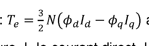
Conformément à une mise en oeuvre de l’invention, on peut déterminer le couple Te de la machine électrique par une formule du type : avec fa le flux magnétique direct, cpq\e flux magnétique en quadrature,
 ld le courant direct courant en quadrature et N le nombre de paires de pôles de la machine
 électrique. In accordance with one implementation of the invention, the torque T e of the electric machine can be determined by a formula of the type: with fa the direct magnetic flux, cp q \e magnetic flux in quadrature, ld the direct current quadrature current and N the number of pole pairs of the machine electric.
Alternativement, cette étape peut mettre en oeuvre tout modèle du couple qui relie le couple et le flux magnétique. Ce modèle peut dépendre également de la vitesse de rotation du rotor de la machine électrique et/ou des mesures de tension. Alternatively, this step can implement any model of the torque which links the torque and the magnetic flux. This model can also depend on the rotational speed of the rotor of the electric machine and/or on voltage measurements.
6) Contrôle de la machine électrique 6) Electric machine control
Cette étape est facultative. This step is optional.
L'invention concerne également un procédé de contrôle, en temps réel, d'une machine électrique, notamment une machine électrique synchrone, pour lequel on réalise les étapes suivantes : The invention also relates to a method for controlling, in real time, an electric machine, in particular a synchronous electric machine, for which the following steps are carried out:
- on détermine le couple de la machine électrique à l'aide du procédé (étapes 1) à 5)) décrit ci-dessus ; et
on contrôle le couple de ladite machine synchrone en fonction du couple déterminé. Pour cette étape, on peut utiliser tout moyen classique de contrôle de la machine électrique, qui prend en en compte le couple de la machine électrique. Par exemple, le contrôle de la machine électrique peut être basée sur une méthode de contrôle direct du couple (en anglais « direct torque control method ») performante, et particulièrement adaptée pour les machines électriques synchrones à pôles saillants. Il peut s’agir par exemple d’une stratégie de contrôle de type MTPA ou MTPV (respectivement de l’anglais « Maximum Torque per Ampere » pouvant être traduit par couple maximum par ampère, et « Maximum Torque per Voltage » pouvant être traduit par couple maximum par volt). - the torque of the electric machine is determined using the method (steps 1) to 5)) described above; and the torque of said synchronous machine is controlled as a function of the determined torque. For this step, it is possible to use any conventional means for controlling the electric machine, which takes into account the torque of the electric machine. For example, the control of the electric machine can be based on a high-performance direct torque control method, and particularly suitable for salient pole synchronous electric machines. It may be for example a control strategy of the MTPA or MTPV type (respectively from the English “Maximum Torque per Ampere” which can be translated by maximum torque per ampere, and “Maximum Torque per Voltage” which can be translated by maximum torque per volt).
En outre, l'invention concerne un système de contrôle d'une machine électrique, notamment une machine électrique synchrone, adapté à appliquer le procédé tel que décrit ci-dessus. Un tel système de contrôle de machine électrique peut comprendre des moyens de contrôle de la machine électrique comportant des moyens de détermination du couple de la machine électrique et des moyens de contrôle du couple de la machine électrique. Les moyens de détermination du couple déterminent le couple de la machine électrique à partir des mesures de courants et de tensions. Il s'agit des courants et des tensions de chacune des trois phases de la machine électrique. Les moyens de contrôle du couple appliquent des tensions aux bornes de la machine électrique en fonction du couple afin d'assurer une consigne de couple pour la machine électrique. Avantageusement, le système de contrôle peut être un contrôleur comprenant des moyens informatiques. Furthermore, the invention relates to a system for controlling an electric machine, in particular a synchronous electric machine, suitable for applying the method as described above. Such an electric machine control system may comprise means for controlling the electric machine comprising means for determining the torque of the electric machine and means for controlling the torque of the electric machine. The torque determining means determine the torque of the electric machine from the current and voltage measurements. These are the currents and voltages of each of the three phases of the electrical machine. The torque control means apply voltages to the terminals of the electric machine as a function of the torque in order to ensure a torque setpoint for the electric machine. Advantageously, the control system can be a controller comprising computer means.
Ce procédé et ce système de contrôle, peuvent être utilisés pour une machine électrique embarquée à bord d'un véhicule, notamment à bord d'un véhicule automobile électrique ou hybride. Toutefois, le système de commande décrit n'est pas limité à cette application et convient pour toutes les applications des machines électriques, y compris les applications stationnaires. This method and this control system can be used for an electrical machine on board a vehicle, in particular on board an electric or hybrid motor vehicle. However, the described control system is not limited to this application and is suitable for all electrical machine applications, including stationary applications.
Comme il va de soi, l’invention ne se limite pas aux seules formes de réalisation du procédé, décrits ci-dessus à titre d’exemple, elle embrasse au contraire toutes les variantes de réalisation. It goes without saying that the invention is not limited solely to the embodiments of the process, described above by way of example, on the contrary it embraces all the variant embodiments.
Exemples d’application
Les caractéristiques et avantages du procédé selon l'invention apparaîtront plus clairement à la lecture des exemples d'application ci-après. Application examples The characteristics and advantages of the method according to the invention will appear more clearly on reading the application examples below.
Les deux exemples concernent des tests expérimentaux pour une machine électrique synchro- réluctante assistée d’aimants permanents selon la conception décrite dans la demande de brevet FR3084536 (W02020/020580). Pour ces deux exemples, on compare le couple de la machine électrique mesuré au couple de la machine électrique déterminé par le procédé selon l’invention. The two examples relate to experimental tests for a synchro-reluctant electrical machine assisted by permanent magnets according to the design described in patent application FR3084536 (W02020/020580). For these two examples, the torque of the electrical machine measured is compared to the torque of the electrical machine determined by the method according to the invention.
La machine électrique utilisé possède les caractéristiques suivantes : The electric machine used has the following characteristics:
- nombre de paires de pôles : 4 - number of pairs of poles: 4
- Résistance : 0,0065 Ohm - Resistance: 0.0065 Ohms
- Nombre de phases : 3 - Number of stages: 3
Vitesse nominale de la machine électrique : 9000 tr/min Rated speed of the electric machine: 9000 rpm
- Tension de bus : 350 V - Bus voltage: 350 V
- Fréquence de découpage : 12000 Hz. - Switching frequency: 12000 Hz.
Pour le premier exemple, le courant de référence est fixé à 400 A en mode de contrôle de courant (en d’autres termes l’amplitude du courant est imposée, et l’angle de courant est automatiquement calculé pour maximiser le couple), et on fait varier la vitesse de rotation de la machine électrique de 500 tr/min à 9000 tr/min. For the first example, the reference current is fixed at 400 A in current control mode (in other words the current amplitude is imposed, and the current angle is automatically calculated to maximize the torque), and the speed of rotation of the electric machine is varied from 500 rpm to 9000 rpm.
La figure 3 illustre pour cet exemple : Figure 3 illustrates for this example:
- En haut à gauche, la courbe de l’amplitude du courant s en A en fonction du temps T en s, qui correspond au courant imposé, - At the top left, the curve of the amplitude of the current s in A as a function of the time T in s, which corresponds to the imposed current,
- En haut à droite, la courbe de la vitesse de rotation mécanique du rotor w en tr/min en fonction du T en s, qui est imposée, - At the top right, the curve of the mechanical rotation speed of the rotor w in rpm as a function of T in s, which is imposed,
En bas à gauche, la courbe de l’angle de courant ô, en ° en fonction du temps T en s, cette valeur mesurée étant celle qui permet de maximiser le couple, Bottom left, the curve of the current angle θ, in ° as a function of time T in s, this measured value being the one which allows the torque to be maximized,
En bas à droite, la courbe de l’amplitude de tension Vabs en V en fonction du temps T en s, qui est une valeur mesurée. Bottom right, the curve of the voltage amplitude V abs in V as a function of time T in s, which is a measured value.
Au moyen de ces mesures, on applique le procédé selon l’invention et on détermine le couple de la machine électrique. By means of these measurements, the method according to the invention is applied and the torque of the electrical machine is determined.
La figure 4 illustre pour cet exemple le couple Te en Nm, avec une première courbe correspondant au couple mesuré MES et une deuxième courbe correspondant au couple
déterminé par le procédé selon l’invention EST. On remarque que les deux courbes sont quasiment superposées. Par conséquent, le procédé selon l’invention permet de déterminer le couple de la machine électrique de manière précise et robuste sur toute la plage de vitesse de rotation. Figure 4 illustrates for this example the torque Te in Nm, with a first curve corresponding to the measured torque MES and a second curve corresponding to the torque determined by the method according to the invention EST. Note that the two curves are almost superimposed. Consequently, the method according to the invention makes it possible to determine the torque of the electrical machine in an accurate and robust manner over the entire rotational speed range.
Pour le deuxième exemple, la vitesse de référence est fixée à 500 tr/min, et on fait varier l’amplitude de courant de la machine électrique de 100 A à 500 A. Pour cet essai, la machine électrique n’est pas en zone de défluxage. For the second example, the reference speed is set at 500 rpm, and the current amplitude of the electric machine is varied from 100 A to 500 A. For this test, the electric machine is not in the zone defluxing.
La figure 5 illustre pour cet exemple : - En haut à gauche, la courbe de l’amplitude du courant s en A en fonction du tempsFigure 5 illustrates for this example: - At the top left, the curve of the current amplitude s in A as a function of time
T en s, qui correspond au courant imposé, T in s, which corresponds to the imposed current,
- En haut à droite, la courbe de la vitesse de rotation du rotor mécanique w en tr/min en fonction du T en s, qui est imposée, - At the top right, the curve of the rotational speed of the mechanical rotor w in rpm as a function of T in s, which is imposed,
En bas à gauche, la courbe de l’angle de courant d, en ° en fonction du temps T en s, cette valeur mesurée étant celle qui permet de maximiser le couple, Bottom left, the curve of the current angle d, in ° as a function of time T in s, this measured value being the one that allows the torque to be maximized,
En bas à droite, la courbe de l’amplitude de tension Vabs en V en fonction du temps T en s, qui est une valeur mesurée. Bottom right, the curve of the voltage amplitude V abs in V as a function of time T in s, which is a measured value.
Au moyen de ces mesures, on applique le procédé selon l’invention et on détermine le couple de la machine électrique. La figure 6 illustre pour cet exemple le couple Te en Nm, avec une première courbe correspondant au couple mesuré MES et une deuxième courbe correspondant au couple déterminé par le procédé selon l’invention EST. On remarque que les deux courbes sont quasiment superposées. Par conséquent, le procédé selon l’invention permet de déterminer le couple de la machine électrique de manière précise et robuste sur toute la plage de variation du courant.
By means of these measurements, the method according to the invention is applied and the torque of the electrical machine is determined. Figure 6 illustrates for this example the torque Te in Nm, with a first curve corresponding to the measured torque MES and a second curve corresponding to the torque determined by the method according to the invention EST. Note that the two curves are almost superimposed. Consequently, the method according to the invention makes it possible to determine the torque of the electrical machine in a precise and robust manner over the entire current variation range.
Claims
1. Procédé de détermination du couple (Te) d’une machine électrique, ladite machine électrique comprenant un rotor, un stator, ledit stator comprenant des bobinages connectés à une pluralité de phases électriques, caractérisé en ce qu’on met en oeuvre les étapes suivantes : a. On mesure (MES) un courant et une tension dans lesdites phases de ladite machine électrique ; b. On détermine une vitesse de rotation électrique dudit rotor, notamment en fonction d’une vitesse de rotation mécanique dudit rotor ; c. On construit un modèle dynamique (MOD) dudit flux magnétique de ladite machine électrique, ledit modèle dynamique (MOD) dudit flux magnétique étant une équation différentielle dudit flux magnétique qui relie le flux magnétique au courant et à la tension desdites phases de la machine électrique, et à la vitesse de rotation électrique dudit rotor ; d. On détermine ledit flux magnétique en appliquant un filtre de Kalman sans parfum adaptatif (KAL) audit modèle dynamique (MOD) dudit flux magnétique, ledit modèle dynamique de flux magnétique étant appliqué aux mesures (MES) de courant et de tension et à la vitesse de rotation électrique déterminée, et la matrice de covariance du bruit du filtre de Kalman sans parfum étant dépendante de ladite vitesse de rotation électrique du rotor ; et e. On détermine le couple (Te) de ladite machine électrique aux moyens desdites mesures (MES) de courant et au moyen dudit flux magnétique déterminé.1. Method for determining the torque (Te) of an electric machine, said electric machine comprising a rotor, a stator, said stator comprising windings connected to a plurality of electric phases, characterized in that the steps following: a. A current and a voltage are measured (MES) in said phases of said electrical machine; b. An electrical speed of rotation of said rotor is determined, in particular as a function of a mechanical speed of rotation of said rotor; vs. A dynamic model (MOD) of said magnetic flux of said electric machine is constructed, said dynamic model (MOD) of said magnetic flux being a differential equation of said magnetic flux which links the magnetic flux to the current and to the voltage of said phases of the electric machine, and the electrical rotational speed of said rotor; d. Said magnetic flux is determined by applying an adaptive fragrance-free Kalman filter (KAL) to said dynamic model (MOD) of said magnetic flux, said dynamic model of magnetic flux being applied to the measurements (MES) of current and voltage and to the speed of electrical rotation determined, and the noise covariance matrix of the scentless Kalman filter being dependent on said electrical rotational speed of the rotor; summer. The torque (Te) of said electric machine is determined by means of said current measurements (MES) and by means of said determined magnetic flux.
2. Procédé de détermination du couple d’une machine électrique selon la revendication 1 , dans lequel on détermine ladite vitesse de rotation électrique ooe dudit rotor par une formule du type we=Nw avec N le nombre de paires de pôles de la machine électrique et w la vitesse de rotation mécanique dudit rotor. 2. Method for determining the torque of an electric machine according to claim 1, in which said electric rotation speed oo e of said rotor is determined by a formula of the type w e =Nw with N the number of pairs of poles of the machine electric and w the mechanical speed of rotation of said rotor.
3. Procédé de détermination du couple d’une machine électrique selon l’une des revendications précédentes, dans lequel ledit modèle dynamique (MOD) de flux magnétique s’écrit :
 avec R la résistance de la machine électrique, ooe la vitesse de rotation électrique, fa le flux magnétique direct, <pq le flux magnétique en quadrature, <pd la dérivée par
rapport au temps du flux magnétique direct, la dérivée par rapport au temps du flux magnétique en quadrature, ld le courant direct, lq le courant en quadrature, Vd la tension directe, Vq la tension en quadrature. 3. Method for determining the torque of an electric machine according to one of the preceding claims, in which said dynamic model (MOD) of magnetic flux is written: with R the resistance of the electric machine, oo e the speed of electric rotation, f a the direct magnetic flux, <p q the magnetic flux in quadrature, <p d the derivative by versus time of the forward magnetic flux, the derivative versus time of the magnetic flux in quadrature, l d the forward current, l q the current in quadrature, V d the forward voltage, V q the voltage in quadrature.
avec R la résistance de la machine électrique, ooe la vitesse de rotation électrique, fa le flux magnétique direct, <pq le flux magnétique en quadrature, <pd la dérivée par
rapport au temps du flux magnétique direct, la dérivée par rapport au temps du flux magnétique en quadrature, ld le courant direct, lq le courant en quadrature, Vd la tension directe, Vq la tension en quadrature. 3. Method for determining the torque of an electric machine according to one of the preceding claims, in which said dynamic model (MOD) of magnetic flux is written: with R the resistance of the electric machine, oo e the speed of electric rotation, f a the direct magnetic flux, <p q the magnetic flux in quadrature, <p d the derivative by versus time of the forward magnetic flux, the derivative versus time of the magnetic flux in quadrature, l d the forward current, l q the current in quadrature, V d the forward voltage, V q the voltage in quadrature.
4. Procédé de détermination du couple d’une machine électrique selon l’une des revendications précédentes, dans lequel on détermine ledit couple (Te) de la machine électrique au moyen de la formule avec le flux magnétique

 direct, le flux magnétique en quadrature, ld le courant direct, lq le courant en quadrature et N le nombre de paires de pôles de ladite machine électrique. 4. Method for determining the torque of an electric machine according to one of the preceding claims, in which said torque (Te) of the electric machine is determined by means of the formula with the magnetic flux direct, the magnetic flux in quadrature, l d the direct current, l q the current in quadrature and N the number of pairs of poles of said electric machine.
5. Procédé de détermination du couple d’une machine électrique selon l’une des revendications précédentes, dans lequel on applique ledit filtre de Kalman sans parfum
 adaptatif à l’équation d’état avec
 correspondant à l’état non mesurable, avec fa le flux magnétique direct, <¾ le flux magnétique en quadrature,
 correspondant à l’entrée de ladite équation d’état, avec R la résistance de la machine électrique, ld le courant direct, lq le courant en quadrature, Vd la tension directe, Vq la tension en quadrature, et
 avec ooe la vitesse de rotation électrique.
5. Method for determining the torque of an electrical machine according to one of the preceding claims, in which said fragrance-free Kalman filter is applied adaptive to the equation of state with corresponding to the non-measurable state, with f a the direct magnetic flux, <¾ the quadrature magnetic flux, corresponding to the input of said equation of state, with R the resistance of the electrical machine, l d the direct current, l q the current in quadrature, V d the direct voltage, V q the voltage in quadrature, and with oo e the electrical rotational speed.
avec ooe la vitesse de rotation électrique.
5. Method for determining the torque of an electrical machine according to one of the preceding claims, in which said fragrance-free Kalman filter is applied adaptive to the equation of state with corresponding to the non-measurable state, with f a the direct magnetic flux, <¾ the quadrature magnetic flux, corresponding to the input of said equation of state, with R the resistance of the electrical machine, l d the direct current, l q the current in quadrature, V d the direct voltage, V q the voltage in quadrature, and with oo e the electrical rotational speed.
6. Procédé de détermination du couple d’une machine électrique selon la revendication 5, dans lequel une fonction qui relie les courants et le flux magnétique est une fonction non linéaire obtenue par une méthode des éléments finis. 6. Method for determining the torque of an electric machine according to claim 5, in which a function which connects the currents and the magnetic flux is a nonlinear function obtained by a finite element method.
7. Procédé de détermination du couple d’une machine électrique selon l’une des revendications précédentes, dans lequel on détermine ledit flux magnétique au moyen des étapes suivantes : i. on initialise k=0, le vecteur d’état xa(0|0) = m(0) et la matrice de covariance P(0|0) = P0 ; ii. à chaque instant k différent de 0, on acquiert lesdites mesures, et on en déduit le vecteur de sortie y(k) ; et
 à chaque instant k différent de 0, on détermine ledit flux magnétique au moyen des équations suivantes :
 avec K le gain du filtre de Kalman sans parfum adaptatif, Pxy une covariance croisée dudit état et desdites mesures, Pyy la covariance prédite des mesures, my la moyenne prédite de la sortie, ld le courant direct, lq le courant en quadrature. 7. Method for determining the torque of an electrical machine according to one of the preceding claims, in which said magnetic flux is determined by means of the following steps: i. we initialize k=0, the state vector x a (0|0)=m(0) and the covariance matrix P(0|0)=P 0 ; ii. at each instant k different from 0, said measurements are acquired, and the output vector y(k) is deduced therefrom; and at each instant k different from 0, said magnetic flux is determined by means of the following equations: with K the gain of the adaptive fragrance-free Kalman filter, P xy a cross covariance of said state and said measurements, P yy the predicted covariance of the measurements, m y the predicted average of the output, l d the direct current, l q the current in quadrature.
8. Procédé de détermination du couple d’une machine électrique selon l’une des revendications précédentes, dans lequel ladite machine électrique est une machine électrique synchrone à pôles saillants, de préférence une machine synchro-réluctante assistée d’aimants permanents. 8. Method for determining the torque of an electric machine according to one of the preceding claims, in which said electric machine is a synchronous electric machine with salient poles, preferably a synchro-reluctant machine assisted by permanent magnets.
9. Procédé de contrôle d’une machine électrique, caractérisé en ce qu’on met en oeuvre les étapes suivantes : a. On détermine le couple de ladite machine électrique au moyen du procédé de détermination dudit couple selon l’une des revendications précédentes ; et b. On contrôle (CTRL) ladite machine électrique au moyen dudit couple déterminé. 9. Method for controlling an electrical machine, characterized in that the following steps are implemented: a. The torque of said electric machine is determined by means of the method for determining said torque according to one of the preceding claims; and B. Said electrical machine is controlled (CTRL) by means of said determined torque.
10. Système de contrôle d’une machine électrique comprenant une machine électrique et un contrôleur pour mettre en oeuvre le procédé de contrôle selon la revendication 9.
10. System for controlling an electric machine comprising an electric machine and a controller for implementing the control method according to claim 9.
Priority Applications (1)
| Application Number | Priority Date | Filing Date | Title |
|---|---|---|---|
| EP22723575.1A EP4331108A1 (en) | 2021-04-26 | 2022-04-15 | Method for determining the torque of an electric machine |
Applications Claiming Priority (2)
| Application Number | Priority Date | Filing Date | Title |
|---|---|---|---|
| FR2104317A FR3122298A1 (en) | 2021-04-26 | 2021-04-26 | Method for determining the torque of an electrical machine |
| FRFR2104317 | 2021-04-26 |
Publications (1)
| Publication Number | Publication Date |
|---|---|
| WO2022228923A1 true WO2022228923A1 (en) | 2022-11-03 |
Family
ID=76375244
Family Applications (1)
| Application Number | Title | Priority Date | Filing Date |
|---|---|---|---|
| PCT/EP2022/060190 WO2022228923A1 (en) | 2021-04-26 | 2022-04-15 | Method for determining the torque of an electric machine |
Country Status (3)
| Country | Link |
|---|---|
| EP (1) | EP4331108A1 (en) |
| FR (1) | FR3122298A1 (en) |
| WO (1) | WO2022228923A1 (en) |
Citations (4)
| Publication number | Priority date | Publication date | Assignee | Title |
|---|---|---|---|---|
| FR2984637A1 (en) | 2011-12-20 | 2013-06-21 | IFP Energies Nouvelles | METHOD FOR DETERMINING THE POSITION AND SPEED OF A ROTOR OF A SYNCHRONOUS ELECTRIC MACHINE |
| WO2019149481A1 (en) * | 2018-01-31 | 2019-08-08 | IFP Energies Nouvelles | Method for establishing the excitation force applied by the swell incident on a movable means of a wave energy system using a model of the drag force |
| WO2020020580A1 (en) | 2018-07-24 | 2020-01-30 | IFP Energies Nouvelles | Rotor for an electrical machine, having asymmetric poles |
| WO2020058131A1 (en) * | 2018-09-20 | 2020-03-26 | IFP Energies Nouvelles | Method for determining the magnetic flux of an electrical machine |
-
2021
- 2021-04-26 FR FR2104317A patent/FR3122298A1/en active Pending
-
2022
- 2022-04-15 WO PCT/EP2022/060190 patent/WO2022228923A1/en active Application Filing
- 2022-04-15 EP EP22723575.1A patent/EP4331108A1/en active Pending
Patent Citations (5)
| Publication number | Priority date | Publication date | Assignee | Title |
|---|---|---|---|---|
| FR2984637A1 (en) | 2011-12-20 | 2013-06-21 | IFP Energies Nouvelles | METHOD FOR DETERMINING THE POSITION AND SPEED OF A ROTOR OF A SYNCHRONOUS ELECTRIC MACHINE |
| WO2019149481A1 (en) * | 2018-01-31 | 2019-08-08 | IFP Energies Nouvelles | Method for establishing the excitation force applied by the swell incident on a movable means of a wave energy system using a model of the drag force |
| WO2020020580A1 (en) | 2018-07-24 | 2020-01-30 | IFP Energies Nouvelles | Rotor for an electrical machine, having asymmetric poles |
| FR3084536A1 (en) | 2018-07-24 | 2020-01-31 | IFP Energies Nouvelles | ELECTRIC MACHINE ROTOR WITH ASYMMETRIC POLES |
| WO2020058131A1 (en) * | 2018-09-20 | 2020-03-26 | IFP Energies Nouvelles | Method for determining the magnetic flux of an electrical machine |
Non-Patent Citations (4)
| Title |
|---|
| "International Conférence on Industrial Electronics, Control and Instrumentation", CENTURY TECHNOLOGIES, vol. 3, pages 1931 - 1936 |
| J. XUS. PANDAY. PANT. LEEB. LAM: "Improved pmsm pulsating torque minimization with iterative learning and sliding mode observer", ANNUAL CONFÉRENCE OF THE IEEE INDUSTRIAL ELECTRONICS SOCIETY, 2000 |
| K. C. YEOG. HEINSF. DE BOER: "Comparison of torque estimators for pmsm", AUSTRALASIAN UNIVERSITIES POWER ENGINEERING CONFÉRENCE, 2008, pages 1 - 6 |
| M. KOTEICH: "Flux estimation algorithms for electric drives: a comparative study", INTERNATIONAL CONFÉRENCE ON RENEWABLE ENERGIES FOR DEVELOPING COUNTRIES, 2016, pages 1 - 6, XP032972837, DOI: 10.1109/REDEC.2016.7577558 |
Also Published As
| Publication number | Publication date |
|---|---|
| EP4331108A1 (en) | 2024-03-06 |
| FR3122298A1 (en) | 2022-10-28 |
Similar Documents
| Publication | Publication Date | Title |
|---|---|---|
| EP2246973B1 (en) | Method for determining the position of the flux vector of a motor | |
| FR2843659A1 (en) | METHOD FOR OPERATING AN OPEN LOOP PARAMETER OBSERVATION DEVICE FOR CONTROLLING A PERMANENT MAGNET MOTOR | |
| FR2843658A1 (en) | METHOD OF CONTROLLING AN ENGINE CONSULTATION TABLE | |
| FR3062762A1 (en) | METHOD OF ESTIMATING THE ANGULAR POSITION OF A ROTOR OF AN ELECTRIC DRIVE SYSTEM | |
| EP2870018B1 (en) | Method for controlling a power train and corresponding system | |
| WO2020244954A1 (en) | Method for estimating the electomagnetic torque of a synchronous electric machine | |
| WO2022228923A1 (en) | Method for determining the torque of an electric machine | |
| WO2020020924A1 (en) | Method for checking the setting of an angular position sensor of a rotor for a vehicle | |
| EP3476037B1 (en) | Method for estimating the position and speed of the rotor of an alternating current machine for a motor vehicle, and corresponding system | |
| EP3138193A2 (en) | Method for estimating the electrical angle of an asynchronous electric machine for a motor vehicle | |
| WO2020058131A1 (en) | Method for determining the magnetic flux of an electrical machine | |
| EP4229746A1 (en) | Device for determining the angular position of a rotor of a rotating electric machine | |
| EP4101065B1 (en) | Method for estimating the electomagnetic torque of a synchronous electric machine | |
| EP3824540B1 (en) | Position and speed determination of a synchron electric machine wounded rotor method | |
| EP3928426B1 (en) | Method for estimating the torque of a synchronous electric machine | |
| FR3131992A1 (en) | Method and system for controlling an electric machine driven by an inverter provided with several switching arms with two servo methods | |
| WO2023062167A1 (en) | Method for estimating the position and speed of the rotor of a permanent-magnet synchronous electric motor | |
| WO2023117402A1 (en) | Method and system for controlling an electric machine driven by an inverter provided with a plurality of switching arms | |
| EP3314742B1 (en) | Control of a synchronous electric machine with a wound rotor | |
| EP4324087A1 (en) | Device for controlling an inverter/rectifier | |
| WO2020016002A1 (en) | Method for estimating the speed and position of a rotor of a wound-rotor synchronous machine | |
| EP2992602B1 (en) | Method of verifying the operation of a motor propulsion plant fitted to an automotive vehicle and corresponding system | |
| FR3121804A1 (en) | Device for controlling an inverter/rectifier | |
| FR2921212A1 (en) | Motor control system for polyphase wound field synchronous dynamoelectric machine (WFSDM), includes inverter which receives gate drive signal and generates motor drive output signals for each phase of WFSDM |
Legal Events
| Date | Code | Title | Description |
|---|---|---|---|
| 121 | Ep: the epo has been informed by wipo that ep was designated in this application |
Ref document number: 22723575 Country of ref document: EP Kind code of ref document: A1 |
|
| WWE | Wipo information: entry into national phase |
Ref document number: 2022723575 Country of ref document: EP |
|
| NENP | Non-entry into the national phase |
Ref country code: DE |
|
| ENP | Entry into the national phase |
Ref document number: 2022723575 Country of ref document: EP Effective date: 20231127 |