WO2022224375A1 - Air sterilization device and air conditioning device using same - Google Patents
Air sterilization device and air conditioning device using same Download PDFInfo
- Publication number
- WO2022224375A1 WO2022224375A1 PCT/JP2021/016169 JP2021016169W WO2022224375A1 WO 2022224375 A1 WO2022224375 A1 WO 2022224375A1 JP 2021016169 W JP2021016169 W JP 2021016169W WO 2022224375 A1 WO2022224375 A1 WO 2022224375A1
- Authority
- WO
- WIPO (PCT)
- Prior art keywords
- air
- ultraviolet light
- frame
- filtering device
- light source
- Prior art date
Links
- 230000001954 sterilising effect Effects 0.000 title claims abstract description 58
- 238000004659 sterilization and disinfection Methods 0.000 title claims abstract description 56
- 238000004378 air conditioning Methods 0.000 title claims abstract description 15
- 238000001914 filtration Methods 0.000 claims description 25
- 230000003287 optical effect Effects 0.000 claims description 2
- 238000011144 upstream manufacturing Methods 0.000 claims 1
- 241000894006 Bacteria Species 0.000 abstract description 27
- 241000700605 Viruses Species 0.000 abstract description 27
- 239000000428 dust Substances 0.000 abstract description 11
- 238000009423 ventilation Methods 0.000 abstract description 2
- 230000002401 inhibitory effect Effects 0.000 abstract 1
- 238000010586 diagram Methods 0.000 description 11
- 238000007664 blowing Methods 0.000 description 6
- 230000007423 decrease Effects 0.000 description 6
- 230000000694 effects Effects 0.000 description 3
- 230000000415 inactivating effect Effects 0.000 description 3
- 230000002779 inactivation Effects 0.000 description 3
- 230000001678 irradiating effect Effects 0.000 description 3
- 239000002184 metal Substances 0.000 description 3
- 230000002093 peripheral effect Effects 0.000 description 3
- 239000002131 composite material Substances 0.000 description 2
- 239000003507 refrigerant Substances 0.000 description 2
- 238000009281 ultraviolet germicidal irradiation Methods 0.000 description 2
- XLYOFNOQVPJJNP-UHFFFAOYSA-N water Substances O XLYOFNOQVPJJNP-UHFFFAOYSA-N 0.000 description 2
- 208000035473 Communicable disease Diseases 0.000 description 1
- 239000013566 allergen Substances 0.000 description 1
- KYKAJFCTULSVSH-UHFFFAOYSA-N chloro(fluoro)methane Chemical compound F[C]Cl KYKAJFCTULSVSH-UHFFFAOYSA-N 0.000 description 1
- 238000009833 condensation Methods 0.000 description 1
- 230000005494 condensation Effects 0.000 description 1
- 238000001816 cooling Methods 0.000 description 1
- 230000009849 deactivation Effects 0.000 description 1
- 230000006866 deterioration Effects 0.000 description 1
- 239000000463 material Substances 0.000 description 1
- 238000000034 method Methods 0.000 description 1
- 235000019645 odor Nutrition 0.000 description 1
- 102000004169 proteins and genes Human genes 0.000 description 1
- 108090000623 proteins and genes Proteins 0.000 description 1
- 239000000126 substance Substances 0.000 description 1
- 238000010792 warming Methods 0.000 description 1
Images


Classifications
-
- A—HUMAN NECESSITIES
- A61—MEDICAL OR VETERINARY SCIENCE; HYGIENE
- A61L—METHODS OR APPARATUS FOR STERILISING MATERIALS OR OBJECTS IN GENERAL; DISINFECTION, STERILISATION OR DEODORISATION OF AIR; CHEMICAL ASPECTS OF BANDAGES, DRESSINGS, ABSORBENT PADS OR SURGICAL ARTICLES; MATERIALS FOR BANDAGES, DRESSINGS, ABSORBENT PADS OR SURGICAL ARTICLES
- A61L9/00—Disinfection, sterilisation or deodorisation of air
- A61L9/16—Disinfection, sterilisation or deodorisation of air using physical phenomena
- A61L9/18—Radiation
- A61L9/20—Ultra-violet radiation
-
- F—MECHANICAL ENGINEERING; LIGHTING; HEATING; WEAPONS; BLASTING
- F24—HEATING; RANGES; VENTILATING
- F24F—AIR-CONDITIONING; AIR-HUMIDIFICATION; VENTILATION; USE OF AIR CURRENTS FOR SCREENING
- F24F3/00—Air-conditioning systems in which conditioned primary air is supplied from one or more central stations to distributing units in the rooms or spaces where it may receive secondary treatment; Apparatus specially designed for such systems
- F24F3/12—Air-conditioning systems in which conditioned primary air is supplied from one or more central stations to distributing units in the rooms or spaces where it may receive secondary treatment; Apparatus specially designed for such systems characterised by the treatment of the air otherwise than by heating and cooling
- F24F3/16—Air-conditioning systems in which conditioned primary air is supplied from one or more central stations to distributing units in the rooms or spaces where it may receive secondary treatment; Apparatus specially designed for such systems characterised by the treatment of the air otherwise than by heating and cooling by purification, e.g. by filtering; by sterilisation; by ozonisation
-
- F—MECHANICAL ENGINEERING; LIGHTING; HEATING; WEAPONS; BLASTING
- F24—HEATING; RANGES; VENTILATING
- F24F—AIR-CONDITIONING; AIR-HUMIDIFICATION; VENTILATION; USE OF AIR CURRENTS FOR SCREENING
- F24F8/00—Treatment, e.g. purification, of air supplied to human living or working spaces otherwise than by heating, cooling, humidifying or drying
- F24F8/20—Treatment, e.g. purification, of air supplied to human living or working spaces otherwise than by heating, cooling, humidifying or drying by sterilisation
- F24F8/22—Treatment, e.g. purification, of air supplied to human living or working spaces otherwise than by heating, cooling, humidifying or drying by sterilisation using UV light
-
- Y—GENERAL TAGGING OF NEW TECHNOLOGICAL DEVELOPMENTS; GENERAL TAGGING OF CROSS-SECTIONAL TECHNOLOGIES SPANNING OVER SEVERAL SECTIONS OF THE IPC; TECHNICAL SUBJECTS COVERED BY FORMER USPC CROSS-REFERENCE ART COLLECTIONS [XRACs] AND DIGESTS
- Y02—TECHNOLOGIES OR APPLICATIONS FOR MITIGATION OR ADAPTATION AGAINST CLIMATE CHANGE
- Y02A—TECHNOLOGIES FOR ADAPTATION TO CLIMATE CHANGE
- Y02A50/00—TECHNOLOGIES FOR ADAPTATION TO CLIMATE CHANGE in human health protection, e.g. against extreme weather
- Y02A50/20—Air quality improvement or preservation, e.g. vehicle emission control or emission reduction by using catalytic converters
Definitions
- the present invention relates to an air sterilization device and an air conditioner using the same.
- Deep ultraviolet rays with a wavelength of 200 nm to 300 nm are known to be effective in sterilizing bacteria and mold, inactivating viruses, and inactivating allergens such as pollen.
- Patent Document 1 discloses a technique for sterilizing (inactivating) bacteria and viruses in the circulating air using ultraviolet rays.
- Patent Document 1 shows that an ultraviolet light emitting diode (hereinafter abbreviated as ultraviolet LED) is used as a light source of ultraviolet light that inactivates bacteria, viruses, and the like.
- ultraviolet LEDs have the advantage that they have a relatively long life and are inexpensive, but they also have the disadvantage that the intensity of the ultraviolet rays emitted from the ultraviolet LEDs is generally low.
- the air containing bacteria and viruses is taken into a space with a high ultraviolet light density (inactivation space), and the intensity is sufficient for bacteria and viruses. UV irradiation is required.
- In order to create such an inactivated space using ultraviolet LEDs it is possible to mount a plurality of ultraviolet LEDs or install a reflecting mirror that reflects the ultraviolet rays emitted from the ultraviolet LEDs and irradiates them to bacteria, viruses, etc. Also, it is necessary to devise measures such as securing a long irradiation time of ultraviolet rays against the air flow.
- the inactivation space In order to secure space for placing multiple UV LEDs and reflecting mirrors, and to ensure a long time for UV irradiation to bacteria and viruses contained in the air, the inactivation space should be arranged along the direction of air flow as much as possible. One option is to keep it for a long time.
- an ultraviolet irradiation device that inactivates bacteria and viruses into an air conditioner or air purifier, it is possible to provide a composite device that can achieve multiple functions. In that case, in order to reduce the size of the composite device, the space inside the internal duct of the air conditioner or air purifier can be used as a space for deactivating the ultraviolet irradiation device.
- the present invention has been made in view of the problems of the prior art, and an air that can efficiently irradiate dust, bacteria, viruses, etc. in the circulating air with ultraviolet rays while suppressing an increase in air blow resistance.
- An object of the present invention is to provide a sterilization device and an air conditioner using the same.
- one typical air sterilization device of the present invention is a frame through which air passes; an ultraviolet light source that emits ultraviolet light having a predetermined divergence angle; a mirror surface that reflects the ultraviolet light and irradiates it toward the air passing through the frame;
- the thickness of the frame in the direction in which the air passes is smaller than the diameter of a circle that is in contact with the inner periphery of the frame, When the ultraviolet light emitted from the ultraviolet light source is reflected by the mirror surface, the reflected light has a smaller divergence angle or convergence angle than the divergence angle at least in the thickness direction of the frame.
- an air sterilization device capable of efficiently irradiating ultraviolet rays to dust, bacteria, viruses, etc. in the circulating air while suppressing an increase in blowing resistance, and an air conditioner using the same.
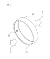
- FIG. 1 is a perspective view of an air sterilization device according to a first embodiment of the present invention.
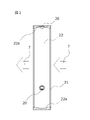
- FIG. 2 is a cross-sectional view in the axial direction of the air filtering device of the first embodiment of the present invention.
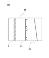
- FIG. 3 is a cross-sectional view of the air sterilization device of the first embodiment of the present invention in the direction perpendicular to the axis.
- FIG. 4 is a perspective view of an air filtering device according to a second embodiment of the invention.
- FIG. 5 is an axial cross-sectional view of an air sterilization device according to a second embodiment of the present invention.
- FIG. 6 is a cross-sectional view of the air sterilization device of the second embodiment of the present invention in the direction perpendicular to the axis.
- FIG. 1 is a perspective view of an air sterilization device according to a first embodiment of the present invention.
- FIG. 2 is a cross-sectional view in the axial direction of the air filtering device of the first embodiment of the present invention
- FIG. 7 is a diagram showing a mounting structure of an air sterilization device according to a third embodiment of the present invention.
- FIG. 8 is a cross-sectional view of a duct configuration using an air sterilization device according to a third embodiment of the present invention.
- FIG. 9 is a diagram showing a partially cut model of a duct configuration using an air filtering device according to a third embodiment of the present invention.
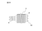
- FIG. 10 is a diagram showing the components of a finned-tube heat exchanger used in the third embodiment of the invention.
- FIG. 11 is a diagram showing the configuration of an air conditioner using an air sterilization device according to a fourth embodiment of the present invention.
- FIG. 12 is a mounting diagram of an air sterilization device to an air conditioner or a duct according to the fifth embodiment of the present invention.
- FIG. 13 is a perspective view of an air filtering device according to a sixth embodiment of the invention.
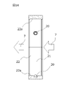
- FIG. 14 is an axial cross-sectional view of an air sterilization device according to a sixth embodiment of the present invention.
- FIG. 15 is a cross-sectional view of the sixth embodiment of the air sterilizing device of the present invention in the direction perpendicular to the axis.
- FIG. 1 is a perspective view of an air filtering device according to a first embodiment.
- FIG. 2 and 3 are diagrams showing the cross-sectional structure of the air sterilization device.
- the present invention is not limited by these embodiments.
- the air sterilization device of this embodiment has a plurality of ultraviolet LEDs mounted as ultraviolet light sources 20 inside a cylindrical frame 21 along the circumferential direction.
- the ultraviolet light source 20 receives power from a power source (not shown), and can emit ultraviolet light from an emission surface facing radially inward of the frame 21 .
- the inner surface of the frame 21 is a mirror surface portion 22 .
- the mirror surface portion 22 has a mirror surface 22a except for the area where the ultraviolet light source 20 is arranged.
- the mirror surface 22a can reflect the ultraviolet light emitted from the ultraviolet light source 20 with high reflectance.
- the mirror surface 22a has the function of repeatedly reflecting the ultraviolet light emitted radially inward from the ultraviolet light source 20 to keep it inside the cylinder of the frame 21 and increasing the ultraviolet light density on the inner surface of the cylinder.
- the air flows in the direction indicated by the air flow 7 arrow. That is, the air flows in the thickness direction (that is, axial direction) of the cylindrical frame 21 .
- the diameter of the cylindrical inner peripheral surface of the frame 21 is larger than the thickness of the frame 21 in the axial direction.
- Air conditioners and other ducts through which air flows have structures such as heat exchangers and filters. This is because it is preferable that the device has a thin shape with respect to the air flow. Further, by reducing the thickness of the frame 21 in the axial direction, it is possible to suppress an increase in blowing resistance.
- the ultraviolet light emitted from the ultraviolet light source 20 has a wavelength of about 200 nm to 300 nm, and is particularly called deep ultraviolet light.
- the ultraviolet light When bacteria and viruses are irradiated with the ultraviolet light, it destroys the proteins that form them. Therefore, it is possible to inactivate bacteria, viruses, etc. by exposing them to ultraviolet light having a wavelength of about 200 nm to 300 nm.
- the amount of energy required to inactivate bacteria and viruses varies depending on the wavelength of ultraviolet light. can be inactivated.
- products that output light with a wavelength of 280 nm are on the market as LEDs that irradiate deep ultraviolet rays, and particularly in this embodiment, it is assumed that an ultraviolet LED with a wavelength of 280 nm or less is mounted.
- Fig. 2 is a cross-sectional view of the cylindrical air sterilization device shown in Fig. 1 taken along a cross section parallel to the thickness direction.
- a plurality of ultraviolet light sources 20 are installed on the inner surface side of the frame 21 so as to be embedded in the center in the thickness direction.
- the inner surface of the frame 21 is a mirror surface portion 22 except for the ultraviolet light source 20, and the mirror surface portion 22 has a concave curved mirror surface 22a that bulges outward when cut along the cross section shown in FIG. .
- the ultraviolet light emitted from the ultraviolet LED, which is the ultraviolet light source 20, is divergent light that spreads at a certain angle. This spread angle (half-value angle) is preferably, for example, 40° to 60°.
- the ultraviolet light emitted from the ultraviolet light source 20 travels while spreading outward in the thickness direction of the frame 21 at a predetermined divergence angle. Inward in the thickness direction (at least in the thickness direction of the frame 21, at a divergence angle smaller than the divergence angle of the ultraviolet light emitted from the ultraviolet light source 20 (including the case where the divergence angle is 0 °) or at a convergence angle ) Because of the reflection, the amount of light leaking out of the frame 21 can be suppressed, and the ultraviolet ray density inside the frame 21 can be increased.
- the shape of the mirror surface (concave surface) 22a may be an arc having a radius of curvature equal to the diameter of the inner surface of the frame 21. With such a spherical shape, the ultraviolet light reflected by the mirror surface (concave surface) 22a is focused near the opposing surface, so the amount of light leaking to the outside of the frame 21 can be further suppressed.
- the shape of the mirror surface (concave surface) 22a is such that, in a cross section parallel to the thickness direction of the frame 21, the ultraviolet light emitted with a spread from the ultraviolet light source 20 is reflected in parallel by the mirror surface (concave surface) 22a.
- a paraboloid structure centered on the optical axis of incident ultraviolet light that is, a paraboloid structure may be used.
- FIG. 3 is a cross-sectional view of the cylindrical air sterilization device shown in FIG. 1 taken along a cross section perpendicular to the thickness direction.
- the ultraviolet light sources 20 are evenly arranged in an odd number along the inner surface of the frame 21 along the circumferential direction, and in particular, the ultraviolet light sources 20 are not arranged on the opposite surface of the ultraviolet light sources 20. If the ultraviolet light source 20 were arranged on the opposite surface of the ultraviolet light source 20, the ultraviolet light would be absorbed and the reflectance would decrease. By facing the mirror surface 22a with the ultraviolet light source 20 sandwiching the center of the frame 21, a decrease in reflectance can be suppressed. By arranging three or more ultraviolet light sources 20 in an odd number such that the opposing surfaces are mirror surfaces, even if the light output intensity of one ultraviolet light source 20 is low, the frame 21 can be The internal ultraviolet light density can be increased.
- FIG. 4 is a perspective view of an air filtering device according to a second embodiment.
- 5 and 6 are diagrams showing the cross-sectional structure of the air sterilization device.
- the present invention is not limited by these embodiments.
- a plurality of ultraviolet LEDs as ultraviolet light sources 20 are mounted inside a cylindrical frame 21 along the circumferential direction.
- the inner surface of the frame 21 is a mirror surface portion 22, a part of which is provided with a circular opening, and an ultraviolet light source 20 is supported at the center of the opening via a support member.
- the emission surface of the ultraviolet light source 20 faces the outside of the frame 21, and the ultraviolet light 28 (FIG. 6) emitted from the emission surface is reflected by the mirror surface 27a of the reflection case 27 on the outside, and reaches the opening. illuminates the inside of the frame 21 (see dotted lines in FIGS. 5 and 6).
- the mirror surface portion 22 has a mirror surface 22a capable of reflecting ultraviolet light emitted from the opening into the frame 21 with high reflectance.
- the mirror surface 22a has the function of repeatedly reflecting the ultraviolet light emitted radially inward to retain it inside the cylinder of the frame 21 and increasing the ultraviolet light density on the inner surface of the cylinder.
- the air flows in the direction indicated by the air flow 7 arrow. That is, the air flows in the thickness direction (that is, axial direction) of the cylindrical frame 21 .
- the diameter of the cylindrical inner peripheral surface of the frame 21 is larger than the thickness of the frame 21 in the axial direction. This is because the air-flow ducts of air conditioners have structures such as heat exchangers and filters, and the air sterilization device installed in the empty space inside the duct is thin against the air flow. This is because the shape is preferable.
- FIG. 5 is a cross-sectional view of the cylindrical air sterilization device shown in FIG. 4 taken along a cross section parallel to the thickness direction.
- a plurality of ultraviolet light sources 20 are installed on the inner surface side of the frame 21 so as to be embedded on the central section in the thickness direction.
- the ultraviolet light source 20 has an emission surface facing inward so as to emit ultraviolet light inward toward the center of the frame 21.
- the ultraviolet light source 20 has an outgoing surface facing outward so as to emit ultraviolet light toward the outside of the frame 21 .
- a reflective case 27 is arranged outside the frame 21 so as to cover the opening, and the surface of the reflective case 27 facing the ultraviolet light source 20 is a mirror surface (concave surface) 27a.
- the mirror surface (concave surface) 27a inside the reflection case 27 converts the light spread from the ultraviolet light source 20 into a form close to parallel light (with a divergence angle smaller than the divergence angle of the ultraviolet light (when the divergence angle is 0°). ) or at a converging angle) and feed it inside the frame 21 .
- the support member that supports the ultraviolet light source 20 with respect to the opening has a thin shape like a column.
- the inner surface of the frame 21 itself is a cylindrical mirror surface portion 22 and is not spherical.
- the ultraviolet light emitted from the mirror surface 27a travels as parallel light, and when reflected by the opposing mirror surface 22a, it is reflected in an elliptical shape. More specifically, the cross-sectional length of the reflected light is constant in the thickness direction of the frame 21 (see the dotted line in FIG. 5), and decreases in the direction perpendicular to the thickness direction of the frame 21 (see the dotted line in FIG. 6). ). Therefore, the ultraviolet ray density within the frame can be made uniform.
- a concave mirror surface 22a may be provided on the inner surface of the frame 21.
- the radius of curvature of the concave surface is sufficiently larger than the diameter to suppress the ultraviolet light leaking outward in the thickness direction of the frame 21. can be considered.
- FIG. 6 is a cross-sectional view of the cylindrical air sterilization device shown in FIG. 4 taken along a cross section perpendicular to the thickness direction.
- the ultraviolet light sources 20 are evenly arranged on the inner surface side of the frame 21 along the circumferential direction.
- the ultraviolet light source 20 is not arranged particularly at a position facing the rear surface of the exit surface of the ultraviolet light source 20 . If the ultraviolet light sources 20 are arranged at opposing positions, the ultraviolet light emitted into the frame 21 through the reflective case 27 may enter the opposing ultraviolet light sources 20 and be absorbed.
- a decrease in reflectance can be suppressed.
- the ultraviolet light inside the frame 21 can be Light density can be increased.
- the structure of the mirror surface (concave surface) 22a facing the ultraviolet light source 20 of the reflection case 27 is a paraboloid, that is, a paraboloid structure in order to reflect the divergent light of the ultraviolet light source 20 and create parallel light as much as possible. and preferred.
- FIG. 7 is a diagram showing the mounting structure of the air sterilization device of the third embodiment.
- FIG. 8 is a cross-sectional view of a duct configuration using the air filtering device of the third embodiment
- FIG. 9 is a diagram showing a partial cut model thereof.
- FIG. 10 is a diagram showing the components of the finned-tube heat exchanger used in the third embodiment.
- the present invention is not limited by these embodiments.
- a plurality of air sterilization devices 23 shown in the first and second embodiments are mounted on the frame 24 .
- the frame 24 has openings that do not block the flow of air passing through the frame 21 .
- the frame 24 shown in FIG. 7 can be mounted in an air conditioning duct 25 through which air such as air conditioning flows, as shown in FIG.
- the number of air filtering devices 23 mounted on the frame 24 can be arbitrarily changed according to the cross-sectional area of the air conditioning duct 25 .
- the filter 26 is made of metal mesh or the like, and has a function of removing dust and the like from the air flowing through the air conditioning duct 25 .
- the heat exchanger 2 has a chlorofluorocarbon refrigerant, water, or the like flowing therein, and has a function of cooling or warming the temperature of the air passing through. In particular, when air is cooled in the heat exchanger 2, dew condensation water may occur on the surface of the heat exchanger 2 depending on the conditions.
- FIG. 9 is a cut model showing the inside structure of the air-conditioning duct 25 shown in FIG. It's like
- the heat exchanger 2 is of a type called a fin-tube type.
- the heat exchanger 2 has a structure in which heat transfer tubes 9 shaped like hairpins penetrate a large number of flat fins 8 .
- the ends of the heat transfer tubes are connected by joints such as the return pipe 10, and the insides of the heat transfer tubes 9 and the return pipe 10 forming a closed circuit form a meandering refrigerant flow path.
- the air sterilization device 23 of this embodiment is relatively thin, so ultraviolet light easily leaks in the thickness direction. Since the heat exchanger 2 is a fin-tube heat exchanger composed of many flat plate fins, the ultraviolet light leaked from the air sterilization device 23 irradiates bacteria, viruses, etc. on the surface of the fins. can be inactivated by In particular, ultraviolet light irradiation can suppress the generation of mold, which is the source of odors.
- the filter 26 is irradiated.
- the filter 26 is made of metal, there is no deterioration due to ultraviolet light, and rather, bacteria, viruses, etc. in the dust deposited on the surface of the filter 26 are inactivated, and part of the dust is decomposed to reduce the deposited dust. can be expected.
- FIG. 11 illustrates the mounting structure of the air sterilization device according to the present embodiment to an air conditioner for railway vehicles. Arrows in FIG. 11 indicate the flow of air.
- the present invention is not limited by these embodiments.
- an air conditioner (air conditioner) 1 is mounted on the roof of the vehicle body 6 .
- the airflow generated by the blowers 3 on both sides of the air conditioner 1 introduces the cabin air into the air conditioner 1 through the air inlet 11 provided with the suction grille 4 .
- the introduced air passes through a filter (not shown), passes through the air sterilizer 5, is cooled or heated by the heat exchanger 2, passes through the blower 3, and returns into the vehicle from the air outlet 12.
- the air sterilization device 5 has a configuration similar to that of the embodiment described above.
- a centrifugal fan is used for the blower 3.
- centrifugal fans and sirocco fans take in air in the direction of their rotating shafts and blow out air in directions perpendicular to their rotating shafts.
- the air sucking direction of the blower 3 coincides with the longitudinal direction of the vehicle body.
- the intake grille 4 is configured by arranging a plurality of substantially flat plate-like blades with their longitudinal directions substantially in the same direction. The angle and length of the blade in the flow direction are set so that the blade surface intersects a straight line connecting the ultraviolet light source of the air sterilization device 5 and the interior of the vehicle, so that the ultraviolet ray from the air sterilization device 5 is It is designed not to pass through. Also, the surface of the blade is coated with a fluorescent substance.
- the ultraviolet light leaked from the air sterilization device 5 irradiates the heat exchanger 2 to which dust, bacteria, viruses, etc. tend to adhere, and exerts the effect of embrittlement of dust and deactivation of bacteria, viruses, etc.
- the ultraviolet light directed to the side opposite to the heat exchanger 2 is irradiated to the filter, top cover, and intake grille 4 of the air conditioner 1 .
- the intake grille 4 is arranged so that the angle of the blades constituting it and the length in the flow direction are such that the blade surface intersects the straight line connecting the ultraviolet light source and the vehicle interior, so that the ultraviolet light is emitted. It is possible to prevent the light from directly leaking into the vehicle and irradiating the passengers in the vehicle.
- the ultraviolet light that hits the blade surface causes the fluorescent material applied to the blade surface to emit light, making it possible to check the operation of the ultraviolet light source from inside the vehicle. You can also
- bacteria, viruses, etc. in the air passing through the air conditioner 1 are inactivated, and the surface of the heat exchanger 2 and the filter are irradiated with ultraviolet light, thereby embrittlement of dust and It can demonstrate the disinfection effect of bacteria, viruses, etc.
- an air conditioner for railway vehicles that can prevent ultraviolet light from leaking into the vehicle interior and can safely supply clean air.
- FIG. 12 shows the mounting structure of the air sterilization device.
- the present invention is not limited by these embodiments.
- a sirocco fan such as the blower 3 shown in FIG. 12 may be used as a blower for an air conditioner and a blower duct.
- centrifugal fans and sirocco fans take in air in the direction of their rotating shafts and blow out air in directions perpendicular to their rotating shafts.
- the structure is such that air is sucked in from the blower suction port 3a on the side, and the air is blown out from the downward blower discharge port 3b by the blades that rotate inside.
- centrifugal fans and sirocco fans have a circular fan inlet 3a. Therefore, an air sterilization device 23 having a diameter that matches the diameter of the blower suction port 3a is fitted and arranged in the blower suction port 3a. By adopting such a structure, air containing bacteria, viruses, etc. is inactivated by the air sterilization device 23 before it is sucked into the blower 3, so that clean air can be blown out from the blower outlet 3b. .
- the ultraviolet light leaking from the air filtering device 23 hits the blades and is reflected and absorbed. can be very low. Therefore, even in an environment where a person exists ahead of the blower outlet 3b due to duct air conditioning or the like, when the air sterilization device 23 is arranged at the blower inlet 3a, the ultraviolet rays leaking from the blower outlet 3b can be suppressed as much as possible. Since a heat exchanger or the like is arranged on the blower inlet 3a side, even if the air sterilization device 23 is arranged at the blower inlet 3a, the leaked ultraviolet light is blocked by the heat exchanger. No problem.
- FIG. 13 is a perspective view of an air filtering device according to a sixth embodiment.
- 14 and 15 are diagrams showing the cross-sectional structure of the air sterilization device.
- the present invention is not limited by these embodiments.
- the air sterilization device of this embodiment has a frame 21 in the shape of a hexagonal cylinder.
- the ultraviolet light source 20 is arranged on the mirror surface 22 facing the ultraviolet light source 20 so that the ultraviolet light source 20 does not exist, the loss at the time of ultraviolet light reflection can be reduced. It is easy to increase the internal ultraviolet ray density.
- the frame 21 by forming the frame 21 into a polygonal cylindrical shape, the space between adjacent frames can be reduced, and the number of frames 21 arranged per unit area can be increased.
- the diameter of the maximum inscribed circle contacting the inner surface of the frame 21 is larger than the thickness of the frame 21 in the axial direction.
- Fig. 14 is a cross-sectional view of the hexagonal cylindrical air sterilization device shown in Fig. 13 taken along a cross section parallel to the thickness direction.
- a plurality of ultraviolet light sources 20 are installed so as to be embedded in the center of the thickness direction on the inner surface side of the frame 21 .
- the inner surface of the frame 21 is a mirror surface portion 22, which has a curved concave mirror surface 22a that bulges outward, as in the first embodiment.
- the ultraviolet light emitted from the ultraviolet light source 20 travels while spreading outward in the thickness direction of the frame 21, and is reflected inward in the thickness direction by the opposing mirror surface (concave surface) 22a, so that it leaks out of the frame 21. The amount of light can be suppressed.
- the shape of the mirror surface (concave surface) 22a may be an arc having a radius of curvature equal to the distance between the inner surfaces of the frame 21 facing each other.
- a paraboloid structure that is, a paraboloid structure that is reflected in parallel by the mirror surface (concave surface) 22a.
- FIG. 15 is a cross-sectional view of the hexagonal cylindrical air sterilization device shown in FIG. 13 taken along a cross section perpendicular to the thickness direction.
- the ultraviolet light sources 20 are evenly arranged on the inner surface side of the frame 21, and in particular, the ultraviolet light sources 20 are not arranged on the surface facing the ultraviolet light sources 20.
- the ultraviolet light sources 20 are arranged at opposing positions, the ultraviolet light emitted from the ultraviolet light sources 20 may enter the opposing ultraviolet light sources 20 and be absorbed, resulting in a decrease in reflectance. By not arranging the ultraviolet light source 20 on the surface facing the ultraviolet light source 20, a decrease in reflectance can be suppressed.
- the ultraviolet ray density inside the frame 21 is increased. be able to. Therefore, especially when the air sterilization device is configured with a polygonal shape as in the present embodiment, the number of ultraviolet light sources 20 is hexagonal when three ultraviolet light sources 20 are used, and octagonal when four ultraviolet light sources 20 are used. It is desirable to form a regular polygonal cylinder having sides twice as large as .
- a pair of gently inclined circular (angular) pyramids whose inner peripheral surfaces are mirror surfaces are formed instead of the frame 21, a pair of gently inclined circular (angular) pyramids whose inner peripheral surfaces are mirror surfaces are formed.
- the frame 21 may be formed by combining the mirror surfaces so as to face each other.
- Ultraviolet light emitted from the ultraviolet light source 20 at a predetermined divergence angle is reflected by one circular (angular) conical mirror surface, directed toward the center of the frame 21, and reflected by the other circular (angular) conical mirror surface. , similarly directed toward the center of the frame 21, it is possible to suppress the leakage of the ultraviolet light to the outside of the frame 21. As shown in FIG.
- ultraviolet light is emitted using an ultraviolet LED that has a relatively long life and is low cost, and the ultraviolet light is repeatedly reflected inside the frame, so that the ultraviolet light density inside the frame can be increased. can.
- the leakage of light in the thickness direction of the frame can be suppressed by the reflection of the mirror surface, which is a concave surface, even if the thickness of the frame is thin, the release of ultraviolet light to the outside of the frame can be relatively suppressed.
Abstract
Provided are: an air sterilization device that can efficiently radiate ultraviolet rays onto dust, bacteria, and viruses in circulating air while inhibiting an increase in ventilation resistance; and an air conditioning device using the same. This air sterilization device has a frame in which air passes through the interior thereof, an ultraviolet light source which emits ultraviolet light having a prescribed angle of divergence, and a mirror surface which reflects the ultraviolet light and radiates the ultraviolet light toward the air passing through the frame, wherein: the thickness of the frame in the direction in which the air passes is less than the diameter of a circle contacting the inner circumference of the frame; and, when the ultraviolet light emitted from the ultraviolet light source is reflected by the mirror surface, the reflected light has an angle of divergence or angle of convergence less than the abovementioned angle of divergence in at least the thickness direction of the frame.
Description
本発明は、空気除菌装置およびそれを用いた空気調和装置に関する。
The present invention relates to an air sterilization device and an air conditioner using the same.
家やオフィス、工場および商業施設などの屋内、飛行機や鉄道、船舶および車などの輸送手段の車内において、浮遊する塵埃や細菌、ウイルス等の多くは、換気等により外部に自然排出されるが、一部は屋内、車内にとどまり、空調機による空気の循環によって拡散することが懸念される。近年、たびたび発生する新型感染症等への関心の高まりから、屋内、車内に残留する細菌・ウイルス等を従来以上に低減することが強く求められている。
Most of the floating dust, bacteria, viruses, etc. are naturally discharged outside by ventilation, etc. in indoors such as homes, offices, factories and commercial facilities, and in vehicles such as airplanes, railways, ships and cars. There is concern that some will remain indoors or in cars and spread through air circulation by air conditioners. In recent years, due to growing interest in new types of infectious diseases that frequently occur, there is a strong demand to reduce bacteria, viruses, etc. that remain indoors and in vehicles more than ever before.
波長が200nm~300nmの深紫外線は、細菌やカビの殺菌、ウイルスの不活化、花粉などのアレルゲンの不活化に効果があることが知られている。
Deep ultraviolet rays with a wavelength of 200 nm to 300 nm are known to be effective in sterilizing bacteria and mold, inactivating viruses, and inactivating allergens such as pollen.
例えば特許文献1には、紫外線を使用して循環する空気中の細菌・ウイルスなどを殺菌(不活化)する技術が開示されている。
For example, Patent Document 1 discloses a technique for sterilizing (inactivating) bacteria and viruses in the circulating air using ultraviolet rays.
特許文献1には、細菌・ウイルスなどを不活化する紫外線の光源として、紫外線発光ダイオード(以降、紫外線LEDと略す)を用いることが示されている。紫外線LEDは、比較的寿命が長く安価であるというメリットがある反面、一般的には紫外線LEDから照射される紫外線の強度が低いというデメリットもある。
Patent Document 1 shows that an ultraviolet light emitting diode (hereinafter abbreviated as ultraviolet LED) is used as a light source of ultraviolet light that inactivates bacteria, viruses, and the like. Ultraviolet LEDs have the advantage that they have a relatively long life and are inexpensive, but they also have the disadvantage that the intensity of the ultraviolet rays emitted from the ultraviolet LEDs is generally low.
空気中の細菌・ウイルスなどを効率的に不活化するためには、細菌・ウイルスなどを含む空気を高い紫外線光線密度の空間(不活化空間)に取り入れて、細菌・ウイルスなどに十分な強度の紫外線を照射する必要がある。そのような不活化空間を、紫外線LEDを用いて創成するには、紫外線LEDを複数個実装したり、紫外線LEDから出射された紫外線を反射させて細菌・ウイルスなどに照射する反射鏡を設けるほか、空気の流れに対して紫外線の照射時間を長く確保するなどの工夫も必要になる。
In order to efficiently inactivate bacteria and viruses in the air, the air containing bacteria and viruses is taken into a space with a high ultraviolet light density (inactivation space), and the intensity is sufficient for bacteria and viruses. UV irradiation is required. In order to create such an inactivated space using ultraviolet LEDs, it is possible to mount a plurality of ultraviolet LEDs or install a reflecting mirror that reflects the ultraviolet rays emitted from the ultraviolet LEDs and irradiates them to bacteria, viruses, etc. Also, it is necessary to devise measures such as securing a long irradiation time of ultraviolet rays against the air flow.
複数の紫外線LEDや反射鏡を配置するスペースを確保するとともに、空気中に含まれる細菌・ウイルスなどに紫外線を照射する時間を長く確保するには、不活化空間を空気の流れ方向に沿って極力長く確保することが一案である。
In order to secure space for placing multiple UV LEDs and reflecting mirrors, and to ensure a long time for UV irradiation to bacteria and viruses contained in the air, the inactivation space should be arranged along the direction of air flow as much as possible. One option is to keep it for a long time.
さらに空気調和装置または空気清浄機に、細菌・ウイルスなどを不活化する紫外線照射装置を組み込むことで、複数の機能を実現できる複合装置を提供できる。その場合、複合装置の小型化を図るべく、空気調和装置または空気清浄機の内部ダクト内の空間を、紫外線照射装置の不活化用空間として利用することもできる。
Furthermore, by incorporating an ultraviolet irradiation device that inactivates bacteria and viruses into an air conditioner or air purifier, it is possible to provide a composite device that can achieve multiple functions. In that case, in order to reduce the size of the composite device, the space inside the internal duct of the air conditioner or air purifier can be used as a space for deactivating the ultraviolet irradiation device.
しかしながら、一般的な空気調和装置または空気清浄機の内部ダクトにおいては、単位時間当たり多量の空気を流す必要があり、その送風抵抗の低減も重要な課題である。一般的な空気調和装置などでは、熱交換器の熱交換性能を向上させつつ送風抵抗を低減するため、空気が流れる断面の断面積を大きく確保している。したがって、空気調和装置などの内部ダクト内を不活化空間として用いた場合、流れる空気に対して十分な量の紫外光を照射するためにダクト長を延長すると、送風抵抗の増大を招くという問題が生じる。
However, in the internal ducts of general air conditioners or air purifiers, it is necessary to flow a large amount of air per unit time, and reducing the blowing resistance is also an important issue. In general air conditioners and the like, a large cross-sectional area is ensured for the cross section through which air flows in order to improve the heat exchange performance of the heat exchanger and reduce the blowing resistance. Therefore, when the inside of an internal duct of an air conditioner or the like is used as an inactivation space, extending the duct length in order to irradiate the flowing air with a sufficient amount of ultraviolet light poses the problem of an increase in blowing resistance. occur.
本発明は、従来技術の課題に鑑みてなされたものであり、送風抵抗の増大を抑制しつつ、循環する空気中の塵埃や細菌・ウイルス等に、効率的に紫外線を照射することができる空気除菌装置ならびにそれを用いた空気調和装置を提供することを目的とする。
The present invention has been made in view of the problems of the prior art, and an air that can efficiently irradiate dust, bacteria, viruses, etc. in the circulating air with ultraviolet rays while suppressing an increase in air blow resistance. An object of the present invention is to provide a sterilization device and an air conditioner using the same.
上記目的を達成するために、代表的な本発明の空気除菌装置の一つは、
内部を空気が通過する枠と、
所定の発散角を持つ紫外光を出射する紫外線光源と、
前記紫外光を反射して、前記枠内を通過する空気に向かって照射する鏡面と、を有し、
前記枠の空気が通過する方向の厚さは、前記枠の内周に接する円の直径よりも小さく、
前記紫外線光源から出射された紫外光が前記鏡面で反射したときに、その反射光は、少なくとも前記枠の厚さ方向において前記発散角よりも小さな発散角または収束角を持つことにより達成される。 In order to achieve the above object, one typical air sterilization device of the present invention is
a frame through which air passes;
an ultraviolet light source that emits ultraviolet light having a predetermined divergence angle;
a mirror surface that reflects the ultraviolet light and irradiates it toward the air passing through the frame;
The thickness of the frame in the direction in which the air passes is smaller than the diameter of a circle that is in contact with the inner periphery of the frame,
When the ultraviolet light emitted from the ultraviolet light source is reflected by the mirror surface, the reflected light has a smaller divergence angle or convergence angle than the divergence angle at least in the thickness direction of the frame.
本発明によれば、送風抵抗の増大を抑制しつつ、循環する空気中の塵埃や細菌・ウイルス等に、効率的に紫外線を照射することができる空気除菌装置ならびにそれを用いた空気調和装置を提供することができる。
上記した以外の課題、構成及び効果は、以下の実施形態の説明により明らかにされる。 According to the present invention, an air sterilization device capable of efficiently irradiating ultraviolet rays to dust, bacteria, viruses, etc. in the circulating air while suppressing an increase in blowing resistance, and an air conditioner using the same. can be provided.
Problems, configurations, and effects other than those described above will be clarified by the following description of the embodiments.
以下、図面を用いて本発明の実施形態を説明する。
Embodiments of the present invention will be described below with reference to the drawings.
[第1の実施形態]
本発明の第1の実施形態を、図1、図2および図3を用いて説明する。図1は、第1の実施形態にかかる空気除菌装置の斜視図である。また図2および図3は、空気除菌装置の断面構造を示す図である。しかし、これらの実施形態によって、本発明が限定されるものではない。 [First Embodiment]
A first embodiment of the present invention will be described with reference to FIGS. 1, 2 and 3. FIG. FIG. 1 is a perspective view of an air filtering device according to a first embodiment. FIG. 2 and 3 are diagrams showing the cross-sectional structure of the air sterilization device. However, the present invention is not limited by these embodiments.
図1に示す様に、本実施形態の空気除菌装置は、円筒状の枠21の内側に紫外線光源20として紫外線LEDを、周方向に沿って複数個実装している。紫外線光源20は、不図示の電源から給電を受けて、枠21の径方向内側を向いた出射面より紫外光を出射可能となっている。枠21の内面は、鏡面部22となっている。鏡面部22は、紫外線光源20が配置された領域を除いて鏡面22aを有する。鏡面22aは、紫外線光源20から出た紫外光を高い反射率で反射できるようになっている。鏡面22aは、紫外線光源20から径方向内側に向けて出射された紫外光を繰り返し反射することによって、枠21の円筒内側に留め、円筒内面の紫外光線密度を高める機能を有する。
As shown in FIG. 1, the air sterilization device of this embodiment has a plurality of ultraviolet LEDs mounted as ultraviolet light sources 20 inside a cylindrical frame 21 along the circumferential direction. The ultraviolet light source 20 receives power from a power source (not shown), and can emit ultraviolet light from an emission surface facing radially inward of the frame 21 . The inner surface of the frame 21 is a mirror surface portion 22 . The mirror surface portion 22 has a mirror surface 22a except for the area where the ultraviolet light source 20 is arranged. The mirror surface 22a can reflect the ultraviolet light emitted from the ultraviolet light source 20 with high reflectance. The mirror surface 22a has the function of repeatedly reflecting the ultraviolet light emitted radially inward from the ultraviolet light source 20 to keep it inside the cylinder of the frame 21 and increasing the ultraviolet light density on the inner surface of the cylinder.
空気の流れ7の矢印が示す方向に、空気が流れる。つまり、円筒形の枠21の厚さ方向(すなわち軸方向)に、空気は流れる。
The air flows in the direction indicated by the air flow 7 arrow. That is, the air flows in the thickness direction (that is, axial direction) of the cylindrical frame 21 .
また図1に示す様に、枠21の円筒内周面の直径は、枠21の軸方向厚さよりも大きい。これは、空気調和装置などの空気が流れるダクトには、熱交換器やフィルターなどの構造物があり、かかる構造物との干渉を避けるため、そのダクト内の空いた空間に実装する空気除菌装置は、空気の流れに対して薄い形状のほうが好ましいためである。また、枠21の軸方向厚さを薄くすることで、送風抵抗の増大を抑制できる。
Also, as shown in FIG. 1, the diameter of the cylindrical inner peripheral surface of the frame 21 is larger than the thickness of the frame 21 in the axial direction. Air conditioners and other ducts through which air flows have structures such as heat exchangers and filters. This is because it is preferable that the device has a thin shape with respect to the air flow. Further, by reducing the thickness of the frame 21 in the axial direction, it is possible to suppress an increase in blowing resistance.
紫外線光源20から出射される紫外線は、200nmから300nm程度の波長を有する特に深紫外線と呼ばれる紫外線であり、細菌やウイルスなどに照射されることで、その形成物質であるタンパク質を破壊する。このため、細菌やウイルス等に200nm~300nm程度の波長の紫外線を当てることで、不活性化が可能となる。
The ultraviolet light emitted from the ultraviolet light source 20 has a wavelength of about 200 nm to 300 nm, and is particularly called deep ultraviolet light. When bacteria and viruses are irradiated with the ultraviolet light, it destroys the proteins that form them. Therefore, it is possible to inactivate bacteria, viruses, etc. by exposing them to ultraviolet light having a wavelength of about 200 nm to 300 nm.
紫外光の波長によって細菌やウイルスなどが不活化するのに必要なエネルギー量は異なるが、200nmから300nm間のいずれかの波長の紫外光であれば、所定量を照射することにより細菌及びウイルスなどを不活化することが可能である。現在、深紫外線を照射するLEDとして、280nmの波長の光を出力する製品が上市されており、とくに本実施形態では、この280nm以下の波長の紫外線LEDを実装することを想定している。
The amount of energy required to inactivate bacteria and viruses varies depending on the wavelength of ultraviolet light. can be inactivated. Currently, products that output light with a wavelength of 280 nm are on the market as LEDs that irradiate deep ultraviolet rays, and particularly in this embodiment, it is assumed that an ultraviolet LED with a wavelength of 280 nm or less is mounted.
細菌やウイルスなどに一定のエネルギーの紫外光を照射し不活化するには、紫外光線密度と照射時間を確保する必要があるが、流れる空気中でしかも流れ方向に厚さのない照射空間では、照射時間を確保することが困難であり、そのため紫外光線密度を高めることが重要である。
In order to inactivate bacteria and viruses by irradiating them with ultraviolet light of a certain energy, it is necessary to ensure the ultraviolet light density and irradiation time. It is difficult to secure the irradiation time, so it is important to increase the ultraviolet light density.
図2は、図1で示す円筒形の空気除菌装置を、厚さ方向に平行な断面で切った断面図である。この図2に示す様に、紫外線光源20は、枠21の内面側で厚さ方向の中央に複数個埋め込まれるように設置されている。そして枠21の内面は、紫外線光源20を除き鏡面部22であり、鏡面部22は、図2に示す断面で切ったとき、外側に膨らむような凹面の曲面形状の鏡面22aを有している。紫外線光源20である紫外線LEDから出射された紫外光は、一定の角度を有して広がる発散光となっている。この広がり角度(半値角とする)は、たとえば40°から60°であると好ましい。
Fig. 2 is a cross-sectional view of the cylindrical air sterilization device shown in Fig. 1 taken along a cross section parallel to the thickness direction. As shown in FIG. 2, a plurality of ultraviolet light sources 20 are installed on the inner surface side of the frame 21 so as to be embedded in the center in the thickness direction. The inner surface of the frame 21 is a mirror surface portion 22 except for the ultraviolet light source 20, and the mirror surface portion 22 has a concave curved mirror surface 22a that bulges outward when cut along the cross section shown in FIG. . The ultraviolet light emitted from the ultraviolet LED, which is the ultraviolet light source 20, is divergent light that spreads at a certain angle. This spread angle (half-value angle) is preferably, for example, 40° to 60°.
紫外線光源20から出射された紫外光は、所定の発散角で枠21の厚さ方向外側に広がりながら進行し、その光軸は枠21の軸線と直交しつつ、対向する鏡面(凹面)22aによって厚さ方向内側に向かって(少なくとも枠21の厚さ方向において、紫外線光源20から出射された紫外光の発散角よりも小さな発散角(発散角が0°である場合を含む)または収束角で)反射するため、枠21の外へ漏れる光の量を抑制することができ、枠21の内側における紫外光線密度を高めることができる。
The ultraviolet light emitted from the ultraviolet light source 20 travels while spreading outward in the thickness direction of the frame 21 at a predetermined divergence angle. Inward in the thickness direction (at least in the thickness direction of the frame 21, at a divergence angle smaller than the divergence angle of the ultraviolet light emitted from the ultraviolet light source 20 (including the case where the divergence angle is 0 °) or at a convergence angle ) Because of the reflection, the amount of light leaking out of the frame 21 can be suppressed, and the ultraviolet ray density inside the frame 21 can be increased.
この鏡面(凹面)22aの形状としては、曲率半径を、この枠21の内面の直径と同等とする円弧としても良い。このような球面形状にすると、鏡面(凹面)22aで反射した紫外光は、対向する面の近辺で焦点を結ぶこととなるので、より枠21の外側へ漏れる光の量を抑制できる。
The shape of the mirror surface (concave surface) 22a may be an arc having a radius of curvature equal to the diameter of the inner surface of the frame 21. With such a spherical shape, the ultraviolet light reflected by the mirror surface (concave surface) 22a is focused near the opposing surface, so the amount of light leaking to the outside of the frame 21 can be further suppressed.
また、この鏡面(凹面)22aの形状としては、枠21の厚さ方向に平行な断面において、紫外線光源20から広がりをもって出射された紫外光が、鏡面(凹面)22aで平行に反射されるような、入射する紫外光の光軸を中心とする放物面、つまりパラボロイド構造としても良い。このような形状にすると、鏡面(凹面)22aで反射した紫外光は、次に対向する鏡面(凹面)22aで反射した際に、対向する面の近辺で焦点を結ぶこととなるので、より枠21の外側へ漏れる光の量を抑制できる。
The shape of the mirror surface (concave surface) 22a is such that, in a cross section parallel to the thickness direction of the frame 21, the ultraviolet light emitted with a spread from the ultraviolet light source 20 is reflected in parallel by the mirror surface (concave surface) 22a. In addition, a paraboloid structure centered on the optical axis of incident ultraviolet light, that is, a paraboloid structure may be used. With such a shape, when the ultraviolet light reflected by the mirror surface (concave surface) 22a is next reflected by the opposite mirror surface (concave surface) 22a, it will be focused in the vicinity of the opposite surface. The amount of light leaking to the outside of 21 can be suppressed.
図3は、図1で示す円筒形の空気除菌装置を、厚さ方向に垂直な断面で切った断面図である。この図3に示す様に、紫外線光源20は枠21の内面側に、周方向に沿って均等に奇数個配置され、とくに紫外線光源20の対向する面には紫外線光源20を配置していない。仮に、紫外線光源20の対向する面に紫外線光源20を配置した場合、それにより紫外光が吸収され反射率が低下する恐れがある。紫外線光源20を枠21の中心を挟んで鏡面22aに対向させることにより、反射率の低下を抑制できる。このように均等に、かつ対向する面が鏡面になるように、紫外線光源20を3つ以上の奇数個配置することで、たとえ1個の紫外線光源20の光出力強度が低くとも、枠21の内部の紫外光線密度を高めることができる。
FIG. 3 is a cross-sectional view of the cylindrical air sterilization device shown in FIG. 1 taken along a cross section perpendicular to the thickness direction. As shown in FIG. 3, the ultraviolet light sources 20 are evenly arranged in an odd number along the inner surface of the frame 21 along the circumferential direction, and in particular, the ultraviolet light sources 20 are not arranged on the opposite surface of the ultraviolet light sources 20. If the ultraviolet light source 20 were arranged on the opposite surface of the ultraviolet light source 20, the ultraviolet light would be absorbed and the reflectance would decrease. By facing the mirror surface 22a with the ultraviolet light source 20 sandwiching the center of the frame 21, a decrease in reflectance can be suppressed. By arranging three or more ultraviolet light sources 20 in an odd number such that the opposing surfaces are mirror surfaces, even if the light output intensity of one ultraviolet light source 20 is low, the frame 21 can be The internal ultraviolet light density can be increased.
[第2の実施形態]
本発明の第2の実施形態を、図4、図5および図6を用いて説明する。図4は、第2の実施形態にかかる空気除菌装置の斜視図である。また図5および図6は、空気除菌装置の断面構造を示す図である。しかし、これらの実施形態によって、本発明が限定されるものではない。 [Second embodiment]
A second embodiment of the present invention will be described with reference to FIGS. 4, 5 and 6. FIG. FIG. 4 is a perspective view of an air filtering device according to a second embodiment. 5 and 6 are diagrams showing the cross-sectional structure of the air sterilization device. However, the present invention is not limited by these embodiments.
図4に示す様に、本実施形態の空気除菌装置は、円筒状の枠21の内側に紫外線光源20として紫外線LEDを、周方向に沿って複数個実装している。枠21の内面は鏡面部22となっており、その一部に円形の開口部が設けてあり、該開口部の中心に支持部材を介して紫外線光源20が支持されている。紫外線光源20の出射面は、枠21の外側に向いており、その出射面から出射された紫外光28(図6)は、外側にある反射ケース27の鏡面27aにて反射して、開口部から枠21内部に照射される(図5,6の点線参照)。
As shown in FIG. 4, in the air sterilization device of this embodiment, a plurality of ultraviolet LEDs as ultraviolet light sources 20 are mounted inside a cylindrical frame 21 along the circumferential direction. The inner surface of the frame 21 is a mirror surface portion 22, a part of which is provided with a circular opening, and an ultraviolet light source 20 is supported at the center of the opening via a support member. The emission surface of the ultraviolet light source 20 faces the outside of the frame 21, and the ultraviolet light 28 (FIG. 6) emitted from the emission surface is reflected by the mirror surface 27a of the reflection case 27 on the outside, and reaches the opening. illuminates the inside of the frame 21 (see dotted lines in FIGS. 5 and 6).
鏡面部22は、開口部から枠21内部に放射された紫外光を高い反射率で反射できる鏡面22aを有する。鏡面22aは、径方向内側に向けて出射された紫外光を繰り返し反射することによって、枠21の円筒内側に留め、円筒内面の紫外光線密度を高める機能を有する。
The mirror surface portion 22 has a mirror surface 22a capable of reflecting ultraviolet light emitted from the opening into the frame 21 with high reflectance. The mirror surface 22a has the function of repeatedly reflecting the ultraviolet light emitted radially inward to retain it inside the cylinder of the frame 21 and increasing the ultraviolet light density on the inner surface of the cylinder.
空気の流れ7の矢印が示す方向に、空気が流れる。つまり、円筒形の枠21の厚さ方向(すなわち軸方向)に、空気は流れる。
The air flows in the direction indicated by the air flow 7 arrow. That is, the air flows in the thickness direction (that is, axial direction) of the cylindrical frame 21 .
また図4に示す様に、枠21の円筒内周面の直径は、枠21の軸方向厚さよりも大きい。これは、空気調和装置などの空気が流れるダクトには、熱交換器やフィルターなどの構造物があり、そのダクト内の空いた空間に実装する空気除菌装置は、空気の流れに対して薄い形状のほうが好ましいためである。
Also, as shown in FIG. 4, the diameter of the cylindrical inner peripheral surface of the frame 21 is larger than the thickness of the frame 21 in the axial direction. This is because the air-flow ducts of air conditioners have structures such as heat exchangers and filters, and the air sterilization device installed in the empty space inside the duct is thin against the air flow. This is because the shape is preferable.
図5は、図4で示す円筒形の空気除菌装置を、厚さ方向に平行な断面で切った断面図である。この図5に示す様に、紫外線光源20は、枠21の内面側で厚さ方向の中央断面上に複数個埋め込まれるように設置されている。また第1の実施形態では、紫外線光源20は枠21の中心方向、内側へ向かって紫外光を発するように、内側を向いた出射面を配置しているが、本実施形態では、紫外線光源20は枠21の外側へ向かって紫外光を発するように、外側を向いた出射面を配置している。
FIG. 5 is a cross-sectional view of the cylindrical air sterilization device shown in FIG. 4 taken along a cross section parallel to the thickness direction. As shown in FIG. 5, a plurality of ultraviolet light sources 20 are installed on the inner surface side of the frame 21 so as to be embedded on the central section in the thickness direction. In addition, in the first embodiment, the ultraviolet light source 20 has an emission surface facing inward so as to emit ultraviolet light inward toward the center of the frame 21. However, in the present embodiment, the ultraviolet light source 20 has an outgoing surface facing outward so as to emit ultraviolet light toward the outside of the frame 21 .
枠21の外側には、開口部を覆うようにして反射ケース27が配置されており、この反射ケース27の紫外線光源20と対向する面が、鏡面(凹面)27aとなっている。本実施形態において反射ケース27内部の鏡面(凹面)27aは、紫外線光源20から広がった光を平行光に近い形に(紫外光の発散角よりも小さな発散角(発散角が0°である場合を含む)または収束角で)反射させ、枠21の内部に供給する。このため、紫外線光源20を開口部に対して支持する支持部材は、柱のように細い形状であると好ましい。
A reflective case 27 is arranged outside the frame 21 so as to cover the opening, and the surface of the reflective case 27 facing the ultraviolet light source 20 is a mirror surface (concave surface) 27a. In this embodiment, the mirror surface (concave surface) 27a inside the reflection case 27 converts the light spread from the ultraviolet light source 20 into a form close to parallel light (with a divergence angle smaller than the divergence angle of the ultraviolet light (when the divergence angle is 0°). ) or at a converging angle) and feed it inside the frame 21 . For this reason, it is preferable that the support member that supports the ultraviolet light source 20 with respect to the opening has a thin shape like a column.
また本実施形態において、枠21自体の内面は円筒状の鏡面部22になっており、球面状とはなっていない。しかし枠21自体が円筒状となっているため、鏡面27aから出射された紫外光は平行光のまま進行し、対向する鏡面22aに反射されたとき、楕円形状となって反射する。より具体的に、反射光の断面長が枠21の厚さ方向には不変であり(図5の点線参照)、枠21の厚さ方向に直交する方向には減少する(図6の点線参照)。このため、枠内の紫外光線密度を均一化することができる。
In addition, in this embodiment, the inner surface of the frame 21 itself is a cylindrical mirror surface portion 22 and is not spherical. However, since the frame 21 itself has a cylindrical shape, the ultraviolet light emitted from the mirror surface 27a travels as parallel light, and when reflected by the opposing mirror surface 22a, it is reflected in an elliptical shape. More specifically, the cross-sectional length of the reflected light is constant in the thickness direction of the frame 21 (see the dotted line in FIG. 5), and decreases in the direction perpendicular to the thickness direction of the frame 21 (see the dotted line in FIG. 6). ). Therefore, the ultraviolet ray density within the frame can be made uniform.
しかしながら、枠21の内面に凹面状の鏡面22aを設けても良く、その場合は凹面の曲率半径を直径よりも十分に大きくとることで、枠21の厚さ方向の外側へ漏れる紫外光を抑制することが考えられる。
However, a concave mirror surface 22a may be provided on the inner surface of the frame 21. In that case, the radius of curvature of the concave surface is sufficiently larger than the diameter to suppress the ultraviolet light leaking outward in the thickness direction of the frame 21. can be considered.
図6は、図4で示す円筒形の空気除菌装置を、厚さ方向に垂直な断面で切った断面図である。この図6に示す様に、紫外線光源20は枠21の内面側に、周方向に沿って均等に配置されている。またとくに紫外線光源20の出射面の背面に対向する位置には、紫外線光源20を配置しない。仮に、対向する位置に紫外線光源20に配置されている場合、反射ケース27を介して枠21内に出射された紫外光が、対向する紫外線光源20に入射して吸収される恐れがある。紫外線光源20の出射面の背面に対向する位置に、紫外線光源20を配置しないことで、反射率の低下を抑制できる。
FIG. 6 is a cross-sectional view of the cylindrical air sterilization device shown in FIG. 4 taken along a cross section perpendicular to the thickness direction. As shown in FIG. 6, the ultraviolet light sources 20 are evenly arranged on the inner surface side of the frame 21 along the circumferential direction. Moreover, the ultraviolet light source 20 is not arranged particularly at a position facing the rear surface of the exit surface of the ultraviolet light source 20 . If the ultraviolet light sources 20 are arranged at opposing positions, the ultraviolet light emitted into the frame 21 through the reflective case 27 may enter the opposing ultraviolet light sources 20 and be absorbed. By not arranging the ultraviolet light source 20 at a position facing the rear surface of the emission surface of the ultraviolet light source 20, a decrease in reflectance can be suppressed.
このように均等に、かつ対向する面が鏡面になるように、紫外線光源20を3つ以上奇数個配置することで、1個の紫外線光源20の光出力強度が弱くとも枠21の内部の紫外光線密度を高めることができる。
By arranging three or more ultraviolet light sources 20 in an odd number such that the surfaces facing each other are mirror surfaces, even if the light output intensity of one ultraviolet light source 20 is weak, the ultraviolet light inside the frame 21 can be Light density can be increased.
また反射ケース27の紫外線光源20と対向する鏡面(凹面)22aの構造は、紫外線光源20の発散光を反射して極力平行な光を作り出すために、放物面、つまりパラボロイド構造となっていると好ましい。
The structure of the mirror surface (concave surface) 22a facing the ultraviolet light source 20 of the reflection case 27 is a paraboloid, that is, a paraboloid structure in order to reflect the divergent light of the ultraviolet light source 20 and create parallel light as much as possible. and preferred.
[第3の実施形態]
本発明の第3の実施形態を、図7、図8、図9及び図10を用いて説明する。図7は、第3の実施形態の空気除菌装置の実装構造を示す図である。図8は、第3の実施形態の空気除菌装置を用いたダクト構成の断面図であり、図9は、その部分カットモデルを示す図である。また図10は、第3の実施形態で用いられているフィンチューブ熱交換器の構成要素を示す図である。しかし、これらの実施形態によって、本発明が限定されるものではない。 [Third embodiment]
A third embodiment of the present invention will be described with reference to FIGS. 7, 8, 9 and 10. FIG. FIG. 7 is a diagram showing the mounting structure of the air sterilization device of the third embodiment. FIG. 8 is a cross-sectional view of a duct configuration using the air filtering device of the third embodiment, and FIG. 9 is a diagram showing a partial cut model thereof. FIG. 10 is a diagram showing the components of the finned-tube heat exchanger used in the third embodiment. However, the present invention is not limited by these embodiments.
本実施形態においては、図7に示す様に、第1の実施形態および第2の実施形態で示した空気除菌装置23をフレーム24に複数実装した。フレーム24は、枠21を通過する空気の流れを阻害しないような開口を備えている。これによって、1つの空気除菌装置23で細菌やウイルスなどを不活化しながら流せる流量が小さくとも、これを複数個用いることで、大量に流れる空気中の細菌やウイルスなどを一度に処理することができる。
In this embodiment, as shown in FIG. 7, a plurality of air sterilization devices 23 shown in the first and second embodiments are mounted on the frame 24 . The frame 24 has openings that do not block the flow of air passing through the frame 21 . As a result, even if one air sterilization device 23 can inactivate bacteria and viruses while the flow rate is small, by using a plurality of devices, bacteria and viruses in a large amount of flowing air can be treated at once. can be done.
また図7で示すフレーム24を、図8に示す様に、空調などの空気を流す空調ダクト25内に実装することが可能となる。フレーム24に実装する空気除菌装置23の数は、空調ダクト25の断面積に応じて任意に変更できる。特に本実施形態の構造は薄型であるため、空調ダクト25の熱交換器2とフィルター26の間に実装することも容易である。フィルター26は、金属製金網などで構成され、空調ダクト25内を流れる空気中の塵埃等を除去する機能を有する。熱交換器2は、内部にフロン系冷媒や水などが流されており、通過する空気の温度を冷やしたり、温めたりする機能を有する。特に、熱交換器2において空気を冷却する場合には、条件によっては結露水が熱交換器2の表面に生じることがある。
Also, the frame 24 shown in FIG. 7 can be mounted in an air conditioning duct 25 through which air such as air conditioning flows, as shown in FIG. The number of air filtering devices 23 mounted on the frame 24 can be arbitrarily changed according to the cross-sectional area of the air conditioning duct 25 . In particular, since the structure of this embodiment is thin, it can be easily mounted between the heat exchanger 2 and the filter 26 of the air conditioning duct 25 . The filter 26 is made of metal mesh or the like, and has a function of removing dust and the like from the air flowing through the air conditioning duct 25 . The heat exchanger 2 has a chlorofluorocarbon refrigerant, water, or the like flowing therein, and has a function of cooling or warming the temperature of the air passing through. In particular, when air is cooled in the heat exchanger 2, dew condensation water may occur on the surface of the heat exchanger 2 depending on the conditions.
図9は、図8で示した空調ダクト25の構造内部を示すカットモデルであり、フレーム24によって囲われているため、空調ダクト25内の空気の流れはすべて、空気除菌装置23を通過するようになっている。
FIG. 9 is a cut model showing the inside structure of the air-conditioning duct 25 shown in FIG. It's like
加えて図10に示す様に、熱交換器2は、フィンチューブ式と呼ばれる形式のものである。熱交換器2は、図10に示すように、多数の平板状のフィン8を、ヘアピン上に成形された伝熱管9が貫いている構造となっている。伝熱管の端部はリターンパイプ10のような接手で接続され、閉回路となった伝熱管9とリターンパイプ10の内部により、蛇行する冷媒流路を構成している。
In addition, as shown in FIG. 10, the heat exchanger 2 is of a type called a fin-tube type. As shown in FIG. 10, the heat exchanger 2 has a structure in which heat transfer tubes 9 shaped like hairpins penetrate a large number of flat fins 8 . The ends of the heat transfer tubes are connected by joints such as the return pipe 10, and the insides of the heat transfer tubes 9 and the return pipe 10 forming a closed circuit form a meandering refrigerant flow path.
本実施形態の空気除菌装置23は、その厚さが比較的薄いため紫外光が厚さ方向に漏れやすくなっている。熱交換器2は、多数の平板上のフィンで構成されたフィンチューブ式の熱交換器となっているため、空気除菌装置23から漏れた紫外光を、フィン表面の細菌やウイルスなどに照射することで不活化できる。特に、紫外光照射により、匂いのもととなるカビの発生を抑制することができる。
The air sterilization device 23 of this embodiment is relatively thin, so ultraviolet light easily leaks in the thickness direction. Since the heat exchanger 2 is a fin-tube heat exchanger composed of many flat plate fins, the ultraviolet light leaked from the air sterilization device 23 irradiates bacteria, viruses, etc. on the surface of the fins. can be inactivated by In particular, ultraviolet light irradiation can suppress the generation of mold, which is the source of odors.
一方で、空気除菌装置23の紫外光は、熱交換器2とは反対側に漏れた場合、フィルター26に照射される。フィルター26が金属製である場合には、紫外光による劣化もなく、むしろフィルター26表面に堆積したホコリの細菌・ウイルスなどを不活化するとともに、ホコリの一部を分解し、堆積したホコリを減らすことも期待できる。
On the other hand, when the ultraviolet light from the air sterilization device 23 leaks to the side opposite to the heat exchanger 2, the filter 26 is irradiated. When the filter 26 is made of metal, there is no deterioration due to ultraviolet light, and rather, bacteria, viruses, etc. in the dust deposited on the surface of the filter 26 are inactivated, and part of the dust is decomposed to reduce the deposited dust. can be expected.
空気除菌装置23の軸方向に漏れ出た紫外光は、多くが熱交換器2およびフィルター26に吸収されるが、その一部が熱交換器2のフィン間の隙間を通じて、またはフィルターの隙間を通過してさらに外側へ漏洩する可能性がある。したがって、この空調ダクト25の両端に、紫外光を漏らさないように、送風ファンを配置したり、または漏れ出た紫外光が直接、空調ダクトの外に出ないようなグリル形状とすることが好ましい。
Most of the ultraviolet light leaking in the axial direction of the air sterilization device 23 is absorbed by the heat exchanger 2 and the filter 26, but part of it passes through the gaps between the fins of the heat exchanger 2 or the gaps of the filter. may leak out through the Therefore, it is preferable to arrange a fan at both ends of the air-conditioning duct 25 so as not to leak ultraviolet light, or to have a grill shape so that the leaked ultraviolet light does not directly go out of the air-conditioning duct. .
[第4の実施形態]
本発明の第4の実施形態を、図11を用いて説明する。図11は、本実施形態にかかる空気除菌装置の鉄道車両用空調装置への実装構造を図示している。図11中、矢印は空気の流れを示す。しかし、これらの実施形態によって、本発明が限定されるものではない。 [Fourth embodiment]
A fourth embodiment of the present invention will be described with reference to FIG. FIG. 11 illustrates the mounting structure of the air sterilization device according to the present embodiment to an air conditioner for railway vehicles. Arrows in FIG. 11 indicate the flow of air. However, the present invention is not limited by these embodiments.
図11に示す様に、車体6の屋根上に、空気調和機(空気調和装置)1が搭載されている。空気調和機1が作動すると、両側にある送風機3が発生する空気流により、車室空気は吸込グリル4が設置された空気吸込口11を通って空気調和機1の内部に導入される。導入された空気は、図示していないがフィルターを通過し、空気除菌装置5を通過し、熱交換器2により冷却または加熱され、送風機3を通って空気吹出口12から車内に戻ることになる。空気除菌装置5は、上述した実施形態と同様な構成である。
As shown in FIG. 11, an air conditioner (air conditioner) 1 is mounted on the roof of the vehicle body 6 . When the air conditioner 1 operates, the airflow generated by the blowers 3 on both sides of the air conditioner 1 introduces the cabin air into the air conditioner 1 through the air inlet 11 provided with the suction grille 4 . The introduced air passes through a filter (not shown), passes through the air sterilizer 5, is cooled or heated by the heat exchanger 2, passes through the blower 3, and returns into the vehicle from the air outlet 12. Become. The air sterilization device 5 has a configuration similar to that of the embodiment described above.
送風機3には、遠心ファンが用いられている。一般に遠心ファンやシロッコファンは、その回転軸の方向に空気を吸い込み、回転軸と垂直な方向に空気を吹き出す形式が用いられる。本実施形態では、送風機3の空気の吸込方向は車体の長手方向と一致する方向となっている。吸込グリル4は、複数の略平板状の羽根の長手方向を略同一方向に配列することにより構成されている。また、この羽根の角度及び流れ方向の長さは、羽根面が、空気除菌装置5の紫外線光源と車室内を結ぶ直線に交差するように設定されて、空気除菌装置5からの紫外線が通過しないようになっている。また、羽根表面には蛍光物質が塗布されている。
A centrifugal fan is used for the blower 3. In general, centrifugal fans and sirocco fans take in air in the direction of their rotating shafts and blow out air in directions perpendicular to their rotating shafts. In this embodiment, the air sucking direction of the blower 3 coincides with the longitudinal direction of the vehicle body. The intake grille 4 is configured by arranging a plurality of substantially flat plate-like blades with their longitudinal directions substantially in the same direction. The angle and length of the blade in the flow direction are set so that the blade surface intersects a straight line connecting the ultraviolet light source of the air sterilization device 5 and the interior of the vehicle, so that the ultraviolet ray from the air sterilization device 5 is It is designed not to pass through. Also, the surface of the blade is coated with a fluorescent substance.
空気除菌装置5から漏れ出た紫外光は、特に塵埃や細菌・ウイルス等が付着しやすい熱交換器2に照射され、塵埃の脆化や細菌・ウイルス等の不活化効果を発揮する。一方、空気除菌装置5から漏れ出た紫外光のうち、熱交換器2とは反対側に向かう紫外光については、空気調和機1のフィルターや上面カバー、吸込グリル4に照射される。
The ultraviolet light leaked from the air sterilization device 5 irradiates the heat exchanger 2 to which dust, bacteria, viruses, etc. tend to adhere, and exerts the effect of embrittlement of dust and deactivation of bacteria, viruses, etc. On the other hand, of the ultraviolet light leaking from the air sterilization device 5 , the ultraviolet light directed to the side opposite to the heat exchanger 2 is irradiated to the filter, top cover, and intake grille 4 of the air conditioner 1 .
吸込グリル4については、前記の通り、それを構成する羽根の角度及び流れ方向の長さが、羽根面が紫外線光源と車室内を結ぶ直線に交差するように配置されているため、紫外光が直接車内に漏洩し、車室内にいる乗客に照射されることを防ぐことができる。さらに、羽根面に照射された紫外光は、羽根面に塗布された蛍光物質を発光させるため、車内から紫外線光源の作動を確認することができ、これにより乗客への安心感や清潔感をアピールすることもできる。
As described above, the intake grille 4 is arranged so that the angle of the blades constituting it and the length in the flow direction are such that the blade surface intersects the straight line connecting the ultraviolet light source and the vehicle interior, so that the ultraviolet light is emitted. It is possible to prevent the light from directly leaking into the vehicle and irradiating the passengers in the vehicle. In addition, the ultraviolet light that hits the blade surface causes the fluorescent material applied to the blade surface to emit light, making it possible to check the operation of the ultraviolet light source from inside the vehicle. You can also
このように、本実施形態によれば、空気調和機1を通過する空気中の細菌・ウイルス等を不活化するとともに、熱交換器2やフィルター表面に紫外光を照射し、塵埃の脆化や細菌・ウイルス等の消毒効果を発揮できる。加えて、車内への紫外光の漏洩も防止でき、安全に、清潔性に優れた空気を供給できる鉄道車両用空気調和機を提供することができる。
As described above, according to the present embodiment, bacteria, viruses, etc. in the air passing through the air conditioner 1 are inactivated, and the surface of the heat exchanger 2 and the filter are irradiated with ultraviolet light, thereby embrittlement of dust and It can demonstrate the disinfection effect of bacteria, viruses, etc. In addition, it is possible to provide an air conditioner for railway vehicles that can prevent ultraviolet light from leaking into the vehicle interior and can safely supply clean air.
[第5の実施形態]
本発明の第5の実施形態を、図12を用いて説明する。図12は、空気除菌装置の実装構造を示している。しかし、これらの実施形態によって、本発明が限定されるものではない。 [Fifth embodiment]
A fifth embodiment of the present invention will be described with reference to FIG. FIG. 12 shows the mounting structure of the air sterilization device. However, the present invention is not limited by these embodiments.
第4の実施形態の鉄道車両用空気調和装置で示したように、空調装置および送風ダクトの送風機として、図12に送風機3として示す様なシロッコファンが用いられている場合がある。一般に遠心ファンやシロッコファンは、その回転軸の方向に空気を吸い込み、回転軸と垂直な方向に空気を吹き出す形式が用いられる。図12では、側面の送風機吸込み口3aから空気を吸い込み、内部で回転する翼によって、下向きの送風機吐き出し口3bから空気を吹き出す構造となっている。
As shown in the railcar air conditioner of the fourth embodiment, a sirocco fan such as the blower 3 shown in FIG. 12 may be used as a blower for an air conditioner and a blower duct. In general, centrifugal fans and sirocco fans take in air in the direction of their rotating shafts and blow out air in directions perpendicular to their rotating shafts. In FIG. 12, the structure is such that air is sucked in from the blower suction port 3a on the side, and the air is blown out from the downward blower discharge port 3b by the blades that rotate inside.
一般に、遠心ファンやシロッコファンは、送風機吸込み口3aが円形となっている。そこで、送風機吸込み口3aの径に一致させた空気除菌装置23を、送風機吸込み口3aに嵌合配置する。このような構造をとることで、細菌やウイルス等を含む空気が送風機3に吸い込まれる前に、空気除菌装置23により不活化されるため、送風機吐き出し口3bから清浄な空気を吹き出すことができる。
In general, centrifugal fans and sirocco fans have a circular fan inlet 3a. Therefore, an air sterilization device 23 having a diameter that matches the diameter of the blower suction port 3a is fitted and arranged in the blower suction port 3a. By adopting such a structure, air containing bacteria, viruses, etc. is inactivated by the air sterilization device 23 before it is sucked into the blower 3, so that clean air can be blown out from the blower outlet 3b. .
加えて、この送風機3の内部で回転する翼が金属製である場合、空気除菌装置23から漏れ出た紫外光は、翼にあたり反射吸収されるため、送風機吐き出し口3bから漏れる光の量を非常に少なくできる。したがって、ダクト空調などで、送風機吐き出し口3bの先に人が存在する環境でも、空気除菌装置23を送風機吸込み口3aに配置した場合、送風機吐き出し口3bから漏れる紫外線を極力抑制できる。なお、送風機吸込み口3a側には熱交換器などが配置されているため、空気除菌装置23を送風機吸込み口3aに配置しても、漏れた紫外光は熱交換器などにより遮られるため、特に問題はない。
In addition, when the blades rotating inside the blower 3 are made of metal, the ultraviolet light leaking from the air filtering device 23 hits the blades and is reflected and absorbed. can be very low. Therefore, even in an environment where a person exists ahead of the blower outlet 3b due to duct air conditioning or the like, when the air sterilization device 23 is arranged at the blower inlet 3a, the ultraviolet rays leaking from the blower outlet 3b can be suppressed as much as possible. Since a heat exchanger or the like is arranged on the blower inlet 3a side, even if the air sterilization device 23 is arranged at the blower inlet 3a, the leaked ultraviolet light is blocked by the heat exchanger. No problem.
[第6の実施形態]
本発明の第6の実施形態を、図13、図14および図15を用いて説明する。図13は、第6の実施形態にかかる空気除菌装置の斜視図である。また図14および図15は、空気除菌装置の断面構造を示す図である。しかし、これらの実施形態によって、本発明が限定されるものではない。 [Sixth Embodiment]
A sixth embodiment of the present invention will be described with reference to FIGS. 13, 14 and 15. FIG. FIG. 13 is a perspective view of an air filtering device according to a sixth embodiment. 14 and 15 are diagrams showing the cross-sectional structure of the air sterilization device. However, the present invention is not limited by these embodiments.
図13に示す様に、本実施形態の空気除菌装置は、枠21を六角筒形としている。本実施形態が示す様に、円筒状の形状でない多角筒形であっても、紫外線光源20に対向する鏡面22に、紫外線光源20が存在しないように配置すれば、紫外光反射時のロスが少なく済み、内部の紫外光線密度を高めやすい。また、枠21を多角筒形状とすることで、隣接する枠同士の間隔を詰めて、単位面積あたりに配設される枠21の数を増大させることができる。なお、枠21の内面に接する最大内接円の直径は、枠21の軸方向厚さよりも大きい。
As shown in FIG. 13, the air sterilization device of this embodiment has a frame 21 in the shape of a hexagonal cylinder. As shown in this embodiment, even in the case of a polygonal cylindrical shape that is not a cylindrical shape, if the ultraviolet light source 20 is arranged on the mirror surface 22 facing the ultraviolet light source 20 so that the ultraviolet light source 20 does not exist, the loss at the time of ultraviolet light reflection can be reduced. It is easy to increase the internal ultraviolet ray density. Further, by forming the frame 21 into a polygonal cylindrical shape, the space between adjacent frames can be reduced, and the number of frames 21 arranged per unit area can be increased. The diameter of the maximum inscribed circle contacting the inner surface of the frame 21 is larger than the thickness of the frame 21 in the axial direction.
図14は、図13で示す六角筒形の空気除菌装置を、厚さ方向に平行な断面で切った断面図である。この図14に示す様に、紫外線光源20を、枠21の内面側で厚さ方向の中央に複数個埋め込まれるように設置されている。そして枠21の内面は鏡面部22となっているが、第1の実施形態と同様に、外側に膨らむような凹面の曲面形状の鏡面22aを有している。紫外線光源20から出射された紫外光は、枠21の厚さ方向外側に広がりながら進行し、対向するこの鏡面(凹面)22aによって厚さ方向内側に向かって反射するため、枠21の外へ漏れる光の量を抑制することができる。
Fig. 14 is a cross-sectional view of the hexagonal cylindrical air sterilization device shown in Fig. 13 taken along a cross section parallel to the thickness direction. As shown in FIG. 14, a plurality of ultraviolet light sources 20 are installed so as to be embedded in the center of the thickness direction on the inner surface side of the frame 21 . The inner surface of the frame 21 is a mirror surface portion 22, which has a curved concave mirror surface 22a that bulges outward, as in the first embodiment. The ultraviolet light emitted from the ultraviolet light source 20 travels while spreading outward in the thickness direction of the frame 21, and is reflected inward in the thickness direction by the opposing mirror surface (concave surface) 22a, so that it leaks out of the frame 21. The amount of light can be suppressed.
第1の実施形態と同様に、この鏡面(凹面)22aの形状としては、曲率半径を、この枠21の内面の向き合う面の距離と同等とする円弧としても良い。また、鏡面(凹面)22aで平行に反射されるような、放物面、つまりパラボロイド構造とすると良い。
As in the first embodiment, the shape of the mirror surface (concave surface) 22a may be an arc having a radius of curvature equal to the distance between the inner surfaces of the frame 21 facing each other. Moreover, it is preferable to have a paraboloid structure, that is, a paraboloid structure that is reflected in parallel by the mirror surface (concave surface) 22a.
図15は、図13で示す六角筒形の空気除菌装置を、厚さ方向に垂直な断面で切った断面図である。この図15に示す様に、紫外線光源20は枠21の内面側に均等に配置され、とくに紫外線光源20の対向する面には、紫外線光源20を配置しない。仮に、対向する位置に紫外線光源20に配置されている場合、紫外線光源20から出射された紫外光が、対向する紫外線光源20に入射し吸収され、反射率が低下する恐れがある。紫外線光源20の対向する面に、紫外線光源20を配置しないことで、反射率の低下を抑制できる。
FIG. 15 is a cross-sectional view of the hexagonal cylindrical air sterilization device shown in FIG. 13 taken along a cross section perpendicular to the thickness direction. As shown in FIG. 15, the ultraviolet light sources 20 are evenly arranged on the inner surface side of the frame 21, and in particular, the ultraviolet light sources 20 are not arranged on the surface facing the ultraviolet light sources 20. As shown in FIG. If the ultraviolet light sources 20 are arranged at opposing positions, the ultraviolet light emitted from the ultraviolet light sources 20 may enter the opposing ultraviolet light sources 20 and be absorbed, resulting in a decrease in reflectance. By not arranging the ultraviolet light source 20 on the surface facing the ultraviolet light source 20, a decrease in reflectance can be suppressed.
このように均等に、かつ対向する面が鏡面になるように紫外線光源20を複数個配置することで、1個の紫外線光源20の光出力強度が弱くとも枠21の内部の紫外光線密度を高めることができる。したがって、特に本実施形態のように多角形で空気除菌装置を構成する場合は、紫外線光源20が3個の場合は六角筒形、4個の場合は八角筒形など、紫外線光源20の個数の2倍の辺を持つ正多角筒形で構成することが望ましい。
By arranging a plurality of ultraviolet light sources 20 evenly in such a manner that the opposing surfaces are mirror surfaces, even if the light output intensity of one ultraviolet light source 20 is weak, the ultraviolet ray density inside the frame 21 is increased. be able to. Therefore, especially when the air sterilization device is configured with a polygonal shape as in the present embodiment, the number of ultraviolet light sources 20 is hexagonal when three ultraviolet light sources 20 are used, and octagonal when four ultraviolet light sources 20 are used. It is desirable to form a regular polygonal cylinder having sides twice as large as .
なお、鏡面22aを凹状の曲面とした枠21を持つ実施形態において、その代わりに、緩やかに傾斜した円(角)錐内周面を鏡面としたものを一対形成し、その円(角)錐鏡面同士を向かい合わせるように組み合わせて、枠21としてもよい。紫外線光源20から所定の発散角で出射された紫外光は、一方の円(角)錐鏡面で反射されて、枠21の中心側に向かい、また他方の円(角)錐鏡面で反射されて、同様に枠21の中心側に向かうため、紫外光が枠21の外部に漏れることを抑制できる。
In addition, in the embodiment having the frame 21 with the mirror surface 22a as a concave curved surface, instead of the frame 21, a pair of gently inclined circular (angular) pyramids whose inner peripheral surfaces are mirror surfaces are formed. The frame 21 may be formed by combining the mirror surfaces so as to face each other. Ultraviolet light emitted from the ultraviolet light source 20 at a predetermined divergence angle is reflected by one circular (angular) conical mirror surface, directed toward the center of the frame 21, and reflected by the other circular (angular) conical mirror surface. , similarly directed toward the center of the frame 21, it is possible to suppress the leakage of the ultraviolet light to the outside of the frame 21. As shown in FIG.
本発明によれば、比較的寿命が長く低コストである紫外線LEDを用いて紫外光を出射し、枠内側にて紫外光の反射を繰り返し行うことにより、枠内側の紫外光線密度を高めることができる。また枠の厚さ方向の光の漏れを凹面である鏡面の反射によって抑えることができるため、枠の厚さを薄くしても比較的紫外光の枠外への放出を抑制することができる。かかる構成によって、送風抵抗を抑制しつつ、熱交換器やフィルターなどに挟まれた狭小な空調ダクト内にも実装可能な、空気除菌装置を実現することが可能となる。
According to the present invention, ultraviolet light is emitted using an ultraviolet LED that has a relatively long life and is low cost, and the ultraviolet light is repeatedly reflected inside the frame, so that the ultraviolet light density inside the frame can be increased. can. In addition, since the leakage of light in the thickness direction of the frame can be suppressed by the reflection of the mirror surface, which is a concave surface, even if the thickness of the frame is thin, the release of ultraviolet light to the outside of the frame can be relatively suppressed. With such a configuration, it is possible to realize an air sterilization device that can be mounted even in a narrow air conditioning duct sandwiched between heat exchangers, filters, etc., while suppressing blowing resistance.
1:空気調和機、2:熱交換器、3:送風機、3a:送風機吸込み口、3b:送風機吐き出し口、4:吸込グリル、5:空気除菌装置、6:車体、7:空気の流れ、8:フィン、9:伝熱管、10:リターンパイプ、11:空気吸込口、20:紫外線光源、21:枠、22:鏡面部、22a:鏡面、23:空気除菌装置、24:フレーム、25:空調ダクト、26:フィルター、27:反射ケース、27a:鏡面(凹面)
1: air conditioner, 2: heat exchanger, 3: blower, 3a: blower inlet, 3b: blower outlet, 4: intake grille, 5: air sterilization device, 6: vehicle body, 7: air flow, 8: fins, 9: heat transfer tube, 10: return pipe, 11: air suction port, 20: ultraviolet light source, 21: frame, 22: mirror surface part, 22a: mirror surface, 23: air sterilization device, 24: frame, 25 : air conditioning duct, 26: filter, 27: reflective case, 27a: mirror surface (concave surface)
Claims (12)
- 内部を空気が通過する枠と、
所定の発散角を持つ紫外光を出射する紫外線光源と、
前記紫外光を反射して、前記枠内を通過する空気に向かって照射する鏡面と、を有し、
前記枠の空気が通過する方向の厚さは、前記枠の内周に接する円の直径よりも小さく、
前記紫外線光源から出射された紫外光が前記鏡面で反射したときに、その反射光は、少なくとも前記枠の厚さ方向において前記発散角よりも小さな発散角または収束角を持つ、
ことを特徴とする空気除菌装置。 a frame through which air passes;
an ultraviolet light source that emits ultraviolet light having a predetermined divergence angle;
a mirror surface that reflects the ultraviolet light and irradiates it toward the air passing through the frame;
The thickness of the frame in the direction in which the air passes is smaller than the diameter of a circle that is in contact with the inner periphery of the frame,
When the ultraviolet light emitted from the ultraviolet light source is reflected by the mirror surface, the reflected light has a smaller divergence angle or convergence angle than the divergence angle at least in the thickness direction of the frame.
An air filtering device characterized by: - 請求項1に記載の空気除菌装置において、
前記紫外線光源の光軸は、前記枠の軸線と交差する、
ことを特徴とする空気除菌装置。 The air filtering device according to claim 1,
the optical axis of the ultraviolet light source intersects the axis of the frame;
An air filtering device characterized by: - 請求項1に記載の空気除菌装置において、
前記枠の内面が、前記鏡面である、
ことを特徴とする空気除菌装置。 The air filtering device according to claim 1,
The inner surface of the frame is the mirror surface,
An air filtering device characterized by: - 請求項1に記載の空気除菌装置において、
前記枠に開口部が形成されており、前記開口部に、前記紫外線光源が、前記紫外光の出射面を前記枠の外側に向けて配置されるとともに、前記出射面に対向して前記鏡面が配置されている、
ことを特徴とする空気除菌装置。 The air filtering device according to claim 1,
An opening is formed in the frame, and the ultraviolet light source is arranged in the opening with an output surface of the ultraviolet light facing the outside of the frame, and the mirror surface faces the output surface. placed,
An air filtering device characterized by: - 請求項1に記載の空気除菌装置において、
前記鏡面は、球面または放物面を含む、
ことを特徴とする空気除菌装置。 The air filtering device according to claim 1,
wherein the mirror surface comprises a spherical surface or a parabolic surface;
An air filtering device characterized by: - 請求項1に記載の空気除菌装置において、
複数個の前記紫外線光源が、前記枠の周方向に沿って等間隔に配置されている、
ことを特徴とする空気除菌装置。 The air filtering device according to claim 1,
A plurality of the ultraviolet light sources are arranged at equal intervals along the circumferential direction of the frame,
An air filtering device characterized by: - 請求項6に記載の空気除菌装置において、
前記枠は、円筒形または多角筒形を有し、前記紫外線光源は、前記枠の中心を挟んで前記鏡面と対向する、
ことを特徴とする空気除菌装置。 In the air filtering device according to claim 6,
The frame has a cylindrical shape or a polygonal cylindrical shape, and the ultraviolet light source faces the mirror surface across the center of the frame.
An air filtering device characterized by: - 請求項1に記載の空気除菌装置において、
前記紫外線光源は、波長200nmから300nmの紫外線を発光する紫外線発光ダイオードである、
ことを特徴とする空気除菌装置。 The air filtering device according to claim 1,
The ultraviolet light source is an ultraviolet light emitting diode that emits ultraviolet light with a wavelength of 200 nm to 300 nm.
An air filtering device characterized by: - 請求項1に記載の空気除菌装置と、熱交換器またはフィルターを、空調ダクトに備えた空気調和装置であって、
前記空気除菌装置は、前記熱交換器の上流側、または前記フィルターの下流側に配置されている、
ことを特徴とする空気調和装置。 An air conditioner comprising the air sterilization device according to claim 1 and a heat exchanger or a filter in an air conditioning duct,
The air sterilization device is arranged upstream of the heat exchanger or downstream of the filter,
An air conditioner characterized by: - 請求項9に記載の空気調和装置であって、
複数個の前記空気除菌装置が、前記空気の流れに対して並列に、前記空調ダクトに設置されたフレーム上に配置されている、
ことを特徴とする空気調和装置。 The air conditioner according to claim 9,
A plurality of the air sterilization devices are arranged on a frame installed in the air conditioning duct in parallel with the flow of the air.
An air conditioner characterized by: - 請求項9に記載の空気調和装置であって、
前記空気除菌装置から出射された紫外線の一部が、前記熱交換器または前記フィルターに照射される、
ことを特徴とする空気調和装置。 The air conditioner according to claim 9,
Part of the ultraviolet rays emitted from the air sterilization device is irradiated to the heat exchanger or the filter.
An air conditioner characterized by: - 請求項9に記載の空気調和装置であって、
前記空気の流れを生じさせる送風機を有し、前記枠を前記送風機の送風機吸込み口に設置した、
ことを特徴とする空気調和装置。 The air conditioner according to claim 9,
having a blower for generating the flow of air, wherein the frame is installed at the blower inlet of the blower;
An air conditioner characterized by:
Priority Applications (2)
| Application Number | Priority Date | Filing Date | Title |
|---|---|---|---|
| JP2022543103A JP7364800B2 (en) | 2021-04-21 | 2021-04-21 | Air sterilization equipment and air conditioning equipment using it |
| PCT/JP2021/016169 WO2022224375A1 (en) | 2021-04-21 | 2021-04-21 | Air sterilization device and air conditioning device using same |
Applications Claiming Priority (1)
| Application Number | Priority Date | Filing Date | Title |
|---|---|---|---|
| PCT/JP2021/016169 WO2022224375A1 (en) | 2021-04-21 | 2021-04-21 | Air sterilization device and air conditioning device using same |
Publications (1)
| Publication Number | Publication Date |
|---|---|
| WO2022224375A1 true WO2022224375A1 (en) | 2022-10-27 |
Family
ID=83723426
Family Applications (1)
| Application Number | Title | Priority Date | Filing Date |
|---|---|---|---|
| PCT/JP2021/016169 WO2022224375A1 (en) | 2021-04-21 | 2021-04-21 | Air sterilization device and air conditioning device using same |
Country Status (2)
| Country | Link |
|---|---|
| JP (1) | JP7364800B2 (en) |
| WO (1) | WO2022224375A1 (en) |
Citations (7)
| Publication number | Priority date | Publication date | Assignee | Title |
|---|---|---|---|---|
| JPS6387438U (en) * | 1986-11-25 | 1988-06-07 | ||
| JP2003336856A (en) * | 2002-05-21 | 2003-11-28 | Fujitsu General Ltd | Air conditioner |
| JP2006034873A (en) * | 2004-07-30 | 2006-02-09 | Fujitsu General Ltd | Air cleaner |
| JP2009511854A (en) * | 2005-10-12 | 2009-03-19 | ヘルマンヌス・ヘルハルドゥス・マリア・シルデルハイス | Auxiliary device to add to the air conditioner |
| WO2014068913A1 (en) * | 2012-10-31 | 2014-05-08 | 株式会社トクヤマ | Ultraviolet sterilizer and sterilization method |
| US20140271353A1 (en) * | 2011-11-02 | 2014-09-18 | Syddansk Universitet | Toroidal-shaped treatment device for disinfecting a fluid such as air or water |
| WO2020170385A1 (en) * | 2019-02-21 | 2020-08-27 | 三菱電機株式会社 | Optical space forming device, sterilization device, air conditioning device, refrigerator, water sterilization device, and detection device |
-
2021
- 2021-04-21 WO PCT/JP2021/016169 patent/WO2022224375A1/en active Application Filing
- 2021-04-21 JP JP2022543103A patent/JP7364800B2/en active Active
Patent Citations (7)
| Publication number | Priority date | Publication date | Assignee | Title |
|---|---|---|---|---|
| JPS6387438U (en) * | 1986-11-25 | 1988-06-07 | ||
| JP2003336856A (en) * | 2002-05-21 | 2003-11-28 | Fujitsu General Ltd | Air conditioner |
| JP2006034873A (en) * | 2004-07-30 | 2006-02-09 | Fujitsu General Ltd | Air cleaner |
| JP2009511854A (en) * | 2005-10-12 | 2009-03-19 | ヘルマンヌス・ヘルハルドゥス・マリア・シルデルハイス | Auxiliary device to add to the air conditioner |
| US20140271353A1 (en) * | 2011-11-02 | 2014-09-18 | Syddansk Universitet | Toroidal-shaped treatment device for disinfecting a fluid such as air or water |
| WO2014068913A1 (en) * | 2012-10-31 | 2014-05-08 | 株式会社トクヤマ | Ultraviolet sterilizer and sterilization method |
| WO2020170385A1 (en) * | 2019-02-21 | 2020-08-27 | 三菱電機株式会社 | Optical space forming device, sterilization device, air conditioning device, refrigerator, water sterilization device, and detection device |
Also Published As
| Publication number | Publication date |
|---|---|
| JP7364800B2 (en) | 2023-10-18 |
| JPWO2022224375A1 (en) | 2022-10-27 |
Similar Documents
| Publication | Publication Date | Title |
|---|---|---|
| US5817276A (en) | Method of UV distribution in an air handling system | |
| CA2818444C (en) | Air purification devices methods and systems | |
| US6328937B1 (en) | Apparatus for killing microorganisms | |
| JP6282678B2 (en) | Air conditioning method and air conditioning system | |
| CA2971014C (en) | Uv decontamination system for climate control systems | |
| CN111256249A (en) | Anti-aerosol virus central air-conditioning sterilization device and air-conditioning system | |
| JP2018162898A (en) | Air conditioning device | |
| JP7018953B2 (en) | Detection device | |
| KR20200135261A (en) | Sterilization apparatus and home appliance including the same | |
| WO2022224375A1 (en) | Air sterilization device and air conditioning device using same | |
| JP6249042B2 (en) | Sterilizer and air conditioner | |
| JP2020132032A (en) | Air conditioner for vehicle | |
| CN211011714U (en) | Anti-aerosol virus central air-conditioning sterilization device and air-conditioning system | |
| JP7153993B2 (en) | Ultraviolet irradiation device and ventilation system using the same | |
| JP7346755B1 (en) | Air sterilization equipment and air conditioning equipment using it | |
| KR102191549B1 (en) | Sterilization apparatus and home appliance including the same | |
| JP7171967B1 (en) | Railroad car air conditioner | |
| US20230181777A1 (en) | Hvac system including sterilization unit | |
| JP2022160293A (en) | Ultraviolet irradiation device, and indoor unit for air conditioner equipped with the ultraviolet irradiation device | |
| JP2023100474A (en) | Air conditioning device | |
| WO2023112235A1 (en) | Indoor unit and air conditioner | |
| JP7168880B2 (en) | air conditioner | |
| JP2022160292A (en) | Ultraviolet irradiation device, and indoor unit for air conditioner equipped with the ultraviolet irradiation device | |
| US20230175719A1 (en) | Air treatment system | |
| JP2023073727A (en) | Ultraviolet irradiation device, indoor unit for air conditioner equipped with the same, air purifier and ventilation duct for housing purposes |
Legal Events
| Date | Code | Title | Description |
|---|---|---|---|
| ENP | Entry into the national phase |
Ref document number: 2022543103 Country of ref document: JP Kind code of ref document: A |
|
| WWE | Wipo information: entry into national phase |
Ref document number: 17920086 Country of ref document: US |
|
| 121 | Ep: the epo has been informed by wipo that ep was designated in this application |
Ref document number: 21937871 Country of ref document: EP Kind code of ref document: A1 |
|
| NENP | Non-entry into the national phase |
Ref country code: DE |