WO2022210835A1 - Multi-shell tank and vessel - Google Patents
Multi-shell tank and vessel Download PDFInfo
- Publication number
- WO2022210835A1 WO2022210835A1 PCT/JP2022/015825 JP2022015825W WO2022210835A1 WO 2022210835 A1 WO2022210835 A1 WO 2022210835A1 JP 2022015825 W JP2022015825 W JP 2022015825W WO 2022210835 A1 WO2022210835 A1 WO 2022210835A1
- Authority
- WO
- WIPO (PCT)
- Prior art keywords
- tank
- inner tank
- pipe
- main body
- outer tank
- Prior art date
Links
- RNFJDJUURJAICM-UHFFFAOYSA-N 2,2,4,4,6,6-hexaphenoxy-1,3,5-triaza-2$l^{5},4$l^{5},6$l^{5}-triphosphacyclohexa-1,3,5-triene Chemical compound N=1P(OC=2C=CC=CC=2)(OC=2C=CC=CC=2)=NP(OC=2C=CC=CC=2)(OC=2C=CC=CC=2)=NP=1(OC=1C=CC=CC=1)OC1=CC=CC=C1 RNFJDJUURJAICM-UHFFFAOYSA-N 0.000 claims description 3
- 239000003063 flame retardant Substances 0.000 claims description 3
- 230000035515 penetration Effects 0.000 description 66
- 239000007789 gas Substances 0.000 description 47
- 238000009413 insulation Methods 0.000 description 32
- 238000012423 maintenance Methods 0.000 description 17
- 239000012530 fluid Substances 0.000 description 16
- 239000007788 liquid Substances 0.000 description 11
- IJGRMHOSHXDMSA-UHFFFAOYSA-N Atomic nitrogen Chemical compound N#N IJGRMHOSHXDMSA-UHFFFAOYSA-N 0.000 description 5
- 238000010276 construction Methods 0.000 description 5
- 230000000694 effects Effects 0.000 description 4
- 229910001873 dinitrogen Inorganic materials 0.000 description 3
- 238000011156 evaluation Methods 0.000 description 3
- 239000012528 membrane Substances 0.000 description 3
- 238000009835 boiling Methods 0.000 description 2
- 238000007596 consolidation process Methods 0.000 description 2
- 230000000149 penetrating effect Effects 0.000 description 2
- 230000002093 peripheral effect Effects 0.000 description 2
- 238000005070 sampling Methods 0.000 description 2
- 239000002775 capsule Substances 0.000 description 1
- 239000002828 fuel tank Substances 0.000 description 1
- 239000001307 helium Substances 0.000 description 1
- 229910052734 helium Inorganic materials 0.000 description 1
- SWQJXJOGLNCZEY-UHFFFAOYSA-N helium atom Chemical compound [He] SWQJXJOGLNCZEY-UHFFFAOYSA-N 0.000 description 1
- 239000001257 hydrogen Substances 0.000 description 1
- 229910052739 hydrogen Inorganic materials 0.000 description 1
- 125000004435 hydrogen atom Chemical class [H]* 0.000 description 1
- 239000011261 inert gas Substances 0.000 description 1
- 238000007689 inspection Methods 0.000 description 1
- 239000011810 insulating material Substances 0.000 description 1
- 238000004519 manufacturing process Methods 0.000 description 1
- 229910052757 nitrogen Inorganic materials 0.000 description 1
- 238000010248 power generation Methods 0.000 description 1
- 238000005086 pumping Methods 0.000 description 1
- 238000010926 purge Methods 0.000 description 1
- 230000002787 reinforcement Effects 0.000 description 1
- 230000000630 rising effect Effects 0.000 description 1
- 239000007921 spray Substances 0.000 description 1
- 238000009834 vaporization Methods 0.000 description 1
- 230000008016 vaporization Effects 0.000 description 1
Images


Classifications
-
- B—PERFORMING OPERATIONS; TRANSPORTING
- B63—SHIPS OR OTHER WATERBORNE VESSELS; RELATED EQUIPMENT
- B63B—SHIPS OR OTHER WATERBORNE VESSELS; EQUIPMENT FOR SHIPPING
- B63B25/00—Load-accommodating arrangements, e.g. stowing, trimming; Vessels characterised thereby
- B63B25/02—Load-accommodating arrangements, e.g. stowing, trimming; Vessels characterised thereby for bulk goods
- B63B25/08—Load-accommodating arrangements, e.g. stowing, trimming; Vessels characterised thereby for bulk goods fluid
- B63B25/12—Load-accommodating arrangements, e.g. stowing, trimming; Vessels characterised thereby for bulk goods fluid closed
- B63B25/16—Load-accommodating arrangements, e.g. stowing, trimming; Vessels characterised thereby for bulk goods fluid closed heat-insulated
-
- F—MECHANICAL ENGINEERING; LIGHTING; HEATING; WEAPONS; BLASTING
- F17—STORING OR DISTRIBUTING GASES OR LIQUIDS
- F17C—VESSELS FOR CONTAINING OR STORING COMPRESSED, LIQUEFIED OR SOLIDIFIED GASES; FIXED-CAPACITY GAS-HOLDERS; FILLING VESSELS WITH, OR DISCHARGING FROM VESSELS, COMPRESSED, LIQUEFIED, OR SOLIDIFIED GASES
- F17C13/00—Details of vessels or of the filling or discharging of vessels
- F17C13/12—Arrangements or mounting of devices for preventing or minimising the effect of explosion ; Other safety measures
-
- F—MECHANICAL ENGINEERING; LIGHTING; HEATING; WEAPONS; BLASTING
- F17—STORING OR DISTRIBUTING GASES OR LIQUIDS
- F17C—VESSELS FOR CONTAINING OR STORING COMPRESSED, LIQUEFIED OR SOLIDIFIED GASES; FIXED-CAPACITY GAS-HOLDERS; FILLING VESSELS WITH, OR DISCHARGING FROM VESSELS, COMPRESSED, LIQUEFIED, OR SOLIDIFIED GASES
- F17C3/00—Vessels not under pressure
- F17C3/02—Vessels not under pressure with provision for thermal insulation
-
- B—PERFORMING OPERATIONS; TRANSPORTING
- B63—SHIPS OR OTHER WATERBORNE VESSELS; RELATED EQUIPMENT
- B63B—SHIPS OR OTHER WATERBORNE VESSELS; EQUIPMENT FOR SHIPPING
- B63B25/00—Load-accommodating arrangements, e.g. stowing, trimming; Vessels characterised thereby
- B63B25/02—Load-accommodating arrangements, e.g. stowing, trimming; Vessels characterised thereby for bulk goods
- B63B25/08—Load-accommodating arrangements, e.g. stowing, trimming; Vessels characterised thereby for bulk goods fluid
- B63B2025/087—Load-accommodating arrangements, e.g. stowing, trimming; Vessels characterised thereby for bulk goods fluid comprising self-contained tanks installed in the ship structure as separate units
-
- F—MECHANICAL ENGINEERING; LIGHTING; HEATING; WEAPONS; BLASTING
- F17—STORING OR DISTRIBUTING GASES OR LIQUIDS
- F17C—VESSELS FOR CONTAINING OR STORING COMPRESSED, LIQUEFIED OR SOLIDIFIED GASES; FIXED-CAPACITY GAS-HOLDERS; FILLING VESSELS WITH, OR DISCHARGING FROM VESSELS, COMPRESSED, LIQUEFIED, OR SOLIDIFIED GASES
- F17C2201/00—Vessel construction, in particular geometry, arrangement or size
- F17C2201/05—Size
- F17C2201/052—Size large (>1000 m3)
-
- F—MECHANICAL ENGINEERING; LIGHTING; HEATING; WEAPONS; BLASTING
- F17—STORING OR DISTRIBUTING GASES OR LIQUIDS
- F17C—VESSELS FOR CONTAINING OR STORING COMPRESSED, LIQUEFIED OR SOLIDIFIED GASES; FIXED-CAPACITY GAS-HOLDERS; FILLING VESSELS WITH, OR DISCHARGING FROM VESSELS, COMPRESSED, LIQUEFIED, OR SOLIDIFIED GASES
- F17C2203/00—Vessel construction, in particular walls or details thereof
- F17C2203/03—Thermal insulations
- F17C2203/0375—Thermal insulations by gas
-
- F—MECHANICAL ENGINEERING; LIGHTING; HEATING; WEAPONS; BLASTING
- F17—STORING OR DISTRIBUTING GASES OR LIQUIDS
- F17C—VESSELS FOR CONTAINING OR STORING COMPRESSED, LIQUEFIED OR SOLIDIFIED GASES; FIXED-CAPACITY GAS-HOLDERS; FILLING VESSELS WITH, OR DISCHARGING FROM VESSELS, COMPRESSED, LIQUEFIED, OR SOLIDIFIED GASES
- F17C2203/00—Vessel construction, in particular walls or details thereof
- F17C2203/06—Materials for walls or layers thereof; Properties or structures of walls or their materials
- F17C2203/0602—Wall structures; Special features thereof
- F17C2203/0612—Wall structures
- F17C2203/0626—Multiple walls
- F17C2203/0629—Two walls
-
- F—MECHANICAL ENGINEERING; LIGHTING; HEATING; WEAPONS; BLASTING
- F17—STORING OR DISTRIBUTING GASES OR LIQUIDS
- F17C—VESSELS FOR CONTAINING OR STORING COMPRESSED, LIQUEFIED OR SOLIDIFIED GASES; FIXED-CAPACITY GAS-HOLDERS; FILLING VESSELS WITH, OR DISCHARGING FROM VESSELS, COMPRESSED, LIQUEFIED, OR SOLIDIFIED GASES
- F17C2205/00—Vessel construction, in particular mounting arrangements, attachments or identifications means
- F17C2205/03—Fluid connections, filters, valves, closure means or other attachments
- F17C2205/0302—Fittings, valves, filters, or components in connection with the gas storage device
- F17C2205/0352—Pipes
-
- F—MECHANICAL ENGINEERING; LIGHTING; HEATING; WEAPONS; BLASTING
- F17—STORING OR DISTRIBUTING GASES OR LIQUIDS
- F17C—VESSELS FOR CONTAINING OR STORING COMPRESSED, LIQUEFIED OR SOLIDIFIED GASES; FIXED-CAPACITY GAS-HOLDERS; FILLING VESSELS WITH, OR DISCHARGING FROM VESSELS, COMPRESSED, LIQUEFIED, OR SOLIDIFIED GASES
- F17C2223/00—Handled fluid before transfer, i.e. state of fluid when stored in the vessel or before transfer from the vessel
- F17C2223/01—Handled fluid before transfer, i.e. state of fluid when stored in the vessel or before transfer from the vessel characterised by the phase
- F17C2223/0146—Two-phase
- F17C2223/0153—Liquefied gas, e.g. LPG, GPL
-
- F—MECHANICAL ENGINEERING; LIGHTING; HEATING; WEAPONS; BLASTING
- F17—STORING OR DISTRIBUTING GASES OR LIQUIDS
- F17C—VESSELS FOR CONTAINING OR STORING COMPRESSED, LIQUEFIED OR SOLIDIFIED GASES; FIXED-CAPACITY GAS-HOLDERS; FILLING VESSELS WITH, OR DISCHARGING FROM VESSELS, COMPRESSED, LIQUEFIED, OR SOLIDIFIED GASES
- F17C2270/00—Applications
- F17C2270/01—Applications for fluid transport or storage
- F17C2270/0102—Applications for fluid transport or storage on or in the water
- F17C2270/0105—Ships
Definitions
- the present disclosure relates to a multi-shell tank and a ship equipped with the same, and more particularly to a piping structure passed between adjacent tanks of the multi-shell tank.
- Patent Document 1 discloses a multi-shell tank of this type.
- the multi-shell tank (liquid gas storage device) of Patent Document 1 includes a tank that stores liquid gas, an inner shell that covers the tank, and an outer shell that covers the inner shell.
- the cold storage space between the tank and the inner shell is filled with vaporized gas from liquid gas.
- the space between the inner and outer shells is filled with nitrogen gas.
- the top of the tank is provided with a dome for passage of the liquid gas cargo pipeline.
- the dome is provided with an evaporative gas pipe that guides the vaporized gas evaporated in the tank to the heater, and the vaporized gas heated by the heater is supplied to the cold insulation space through the supply pipe.
- the tanks are passed through in order to supply gas to and discharge gas from between the tanks, and , may be provided with piping extending to the exterior of the multi-shell tank.
- piping extending to the exterior of the multi-shell tank.
- the inner shell is provided with a projecting portion that penetrates the outer shell and protrudes to the exposure. passed into the space.
- the projecting portion of the inner shell is provided at a position away from the dome where the tank piping is concentrated.
- the pipe penetration part Reinforcement and strength evaluation are required for the part of the tank through which the pipe penetrates (hereinafter referred to as the pipe penetration part). Also, if the tank is heat-insulated, special heat-insulating work is required for the pipe penetration. For this reason, the more pipe penetrations there are, the more man-hours are required in manufacturing and the more inspection points are required in maintenance. Furthermore, if the pipe penetrations are dispersed in the multi-shell tank, the accessibility and maintainability of the valves and instruments installed in the pipes will be lowered, so it is desirable that the pipe penetrations be collectively arranged.
- the present disclosure has been made in view of the above circumstances, and its purpose is to propose a piping structure in a multi-shell tank in which the pipe penetrations of the tank can be integrated.
- a multi-shell tank includes: An inner tank, an outer tank containing the inner tank, an outermost shell containing the inner tank and the outer tank, and an inter-tank pipe passing between the inner tank and the outer tank,
- the inner tank has an inner tank main body and an inner tank protruding portion projecting from the inner tank main body through the outermost shell to the outside of the outermost shell
- the outer tank has an outer tank main body that covers the inner tank main body, and an outer tank protrusion that penetrates the outermost shell and protrudes to the outside of the outermost shell and surrounds at least a portion of the inner tank protrusion.
- the outer tank protruding part has at least a part thereof exposed to the outside of the outermost shell,
- the inter-tank pipe passes between the inner tank main body and the outer tank main body, passes between the inner tank protruding portion and the outer tank protruding portion, and extends from the outer tank protruding portion to the outside of the outer tank protruding portion. It is characterized by extending outward through the bath exposed portion.
- the multi-shell tank according to the present disclosure is An inner tank, an outer tank containing the inner tank, an outermost shell containing the inner tank and the outer tank, and an inter-tank pipe passing between the inner tank and the outer tank
- the inner tank has an inner tank main body and an inner tank protruding portion projecting from the inner tank main body through the outer tank and the outermost shell to the outside of the outermost shell
- the outer tank has an outer tank body covering the inner tank body
- the inner tank protruding part has at least a part of an inner tank exposed part exposed to the outside of the outermost shell
- the inter-tank pipe is passed between the inner tank main body and the outer tank main body, passes through the inner tank protruding part and into the inner tank protruding part, and is connected to the inner tank protruding part. It is characterized by extending outward through the exposed portion.
- the multi-shell tank according to the present disclosure is an inner tank, an outer tank containing the inner tank, an outermost shell containing the inner tank and the outer tank, an inter-tank pipe passing between the inner tank and the outer tank, and the inner tank Equipped with an inner tank pipe that communicates the inside of the tank with the outside
- the inner tank has an inner tank body
- the outer tank has an outer tank main body that covers the inner tank main body, and an outer tank protruding portion that penetrates the outermost shell from the outer tank main body and protrudes to the outside of the outermost shell
- the outer tank protruding part has at least a part thereof exposed to the outside of the outermost shell
- the inter-tank pipe passes between the inner tank main body and the outer tank main body, passes through the inside of the outer tank protruding part, penetrates the outer tank exposed part of the outer tank protruding part, and extends to the outside. served,
- the inner tank pipe passes through the inner tank main body from within the inner tank main body, passes through the inside of the
- a ship according to the present disclosure is characterized by comprising a hull and the multi-hull tank supported by the hull.
- the pipe penetrations of the multi-shell tank are integrated into the outer tank protrusion and the inner tank protrusion (or the inner tank protrusion or the outer tank protrusion). .
- the pipe penetrations provided in the multi-shell tank in this way, an improvement in workability during construction of the tank can be expected.
- the maintenance points are concentrated by consolidating the pipe penetrations, so maintenance is easy. and improved accessibility can be expected.
- the inter-tank piping passes through the outer tank projecting portion or the inner tank projecting portion to reach the exposure, and the inter-tank piping extends between the outer tank and the outermost shell. does not pass through space. Therefore, it is possible to prevent the fluid flowing through the inter-tank pipe from leaking into the space between the outer tank and the outermost shell.
- FIG. 1 is a schematic side view of a ship provided with a multi-shell tank according to an embodiment.
- FIG. 2 is a schematic cross-sectional view of a multi-shell tank to which the piping structure according to the first example is applied.
- FIG. 3 is a schematic cross-sectional view of a multi-shell tank to which the piping structure according to the first example is applied.
- FIG. 4 is a schematic cross-sectional view of a multi-shell tank to which the piping structure according to the second example is applied.
- FIG. 5 is a schematic cross-sectional view of a multi-shell tank to which the piping structure according to the third example is applied.
- FIG. 6 is a schematic sectional view of a multi-shell tank to which the piping structure according to the fourth example is applied.
- FIG. 7 is a schematic cross-sectional view of a multi-shell tank to which the piping structure according to the fifth example is applied.
- the “inner side” means the side near the center of the space in the inner tank of the multi-shell tank
- the “outer side” means the side far from the center of the space in the inner tank of the multi-shell tank. means side.
- FIG. 1 is a schematic side view of a ship 1 equipped with a multi-shell tank 2 according to this embodiment.
- the ship 1 comprises at least one multi-hull tank 2 and a hull 11 on which the multi-hull tank 2 is mounted.
- the ship 1 is a liquefied gas carrier that carries low-temperature liquefied gas. Examples of liquefied gas include LNG, liquefied nitrogen, liquefied hydrogen, and liquefied helium.
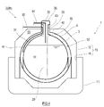
- FIG. 2 is a schematic cross-sectional view of a multi-shell tank 2 (2A) to which the piping structure according to the first example is applied.
- the multi-shell tank 2 includes an inner tank 3 , an outer tank 4 containing the inner tank 3 , and an outermost shell 15 containing the inner tank 3 and the outer tank 4 .
- the outermost shell 15 according to this embodiment is formed by a tank cover 12 covering the upper portion of the outer tank 4 and retaining walls 14 covering the sides and bottom of the outer tank 4 .
- the upper portion of the outer tank 4 may be covered with a portion of the hull 11 instead of the tank cover 12 .
- the retaining wall 14 may be formed, for example, by a part of the hull 11 .
- both the inner tank 3 and the outer tank 4 are spherical.
- a spherical shape includes a capsule shape and an elliptical shape in addition to a true spherical shape.
- the inner tub 3 and the outer tub 4 are not necessarily limited to a spherical shape, and may be rectangular.
- a storage space 51 inside the inner tank 3 contains liquefied gas. Between the inner tank 3 and the outer tank 4, an airtight space (hereinafter referred to as cold insulation space 52) is formed. A heat insulating material is arranged in the cold insulation space 52 . Furthermore, the cold insulation space 52 is filled with a gas having a boiling point higher than the boiling point of the liquefied gas stored in the storage space 51 . In this embodiment, the cold insulation space 52 is filled with the vaporized gas of the liquefied gas in the storage space 51, and this vaporized gas is combustible. In this way, when the storage space 51 and the cold insulation space 52 are filled with the same gas, the cold insulation space 52 may communicate with the cold insulation space 52 in the inner tank 3 .
- the holding space 53 is filled with, for example, a non-combustible gas such as nitrogen gas or inert gas, a flame-retardant gas, or dry air.
- a non-combustible gas such as nitrogen gas or inert gas, a flame-retardant gas, or dry air.
- the holding space 53 according to this embodiment is filled with nitrogen gas.
- the inner tank 3 has an inner tank main body 31 and an inner tank protruding portion 32 that protrudes upward from the top of the inner tank main body 31 .
- the inner tank protruding part 32 protrudes toward the exposed space above the tank cover 12 in order to lead the pipe passing through the inside of the inner tank 3 directly to the exposure without passing through other spaces. 3 to form a space communicated with the inside.
- the inner tank projecting portion 32 has a dome shape and is generally called an inner tank dome.
- the inner tank projecting portion 32 includes a tubular peripheral wall rising from the inner tank main body 31 and a ceiling wall closing an upper opening of the peripheral wall. The upper portion of the inner tank projecting portion 32 projects upward from the tank cover 12 and is exposed.
- the inner tank 3 is provided with a tower 20 extending from the top of the inner tank projecting portion 32 to the bottom of the inner tank body 31 .
- a pump for pumping up the liquefied gas is installed in the lower part of the tower 20 .
- a liquid feed pipe and an electric pipe are connected to the pump, and these liquid feed pipe and electric pipe pass through the inside of the tower 20 and extend to the outside through the inner tank projecting portion 32 .
- the pump arranged at the bottom of the tower 20 may be omitted.
- the inner tank 3 is provided with at least one inner tank pipe 91 that communicates the inside of the inner tank 3 with the outside of the multi-shell tank 2 .
- the inner tank pipe 91 is open inside the inner tank 3, and the inner tank pipe 91 extends outside through the inner tank 3 (or the inner tank 3 and the outer tank 4). there is The inner tank pipe 91 may pass through the tower 20 . Although one inner tank pipe 91 is shown representatively in FIG.
- the inner tank pipe 91 is, for example, a pneumatic pipe that guides the boil-off gas generated by vaporization of the liquefied gas in the inner tank 3 from the inner tank 3 to other equipment outside the multi-shell tank 2 .
- Other equipment is, for example, a propulsion engine, a power generation engine, a reliquefaction device, an atmospheric release device, and the like.
- the inner tank pipe 91 is not limited to a pneumatic pipe, and may be, for example, a liquid pipe for transporting cargo, a sampling pipe, a spray pipe, or the like.
- At least one inter-tank pipe 92 is passed through the cold insulation space 52 between the inner tank 3 and the outer tank 4 .
- the inter-tank pipe 92 may be appropriately supported by a structural member arranged in the cold insulation space 52 .
- the inter-tank pipe 92 is passed between the inner tank main body 31 and the outer tank main body 41, and penetrates at least one of the inner tank 3 and the outer tank 4 and extends to the outside.
- One end of the inter-tank pipe 92 may open at an arbitrary position between the inner tank main body 31 and the outer tank main body 41 in the cold insulation space 52 .
- the inter-tank pipe 92 may branch/merge in the cold insulation space 52 .
- the inter-tank pipe 92 may be any one of a liquid feed pipe, an air pipe, and an electric pipe. Further, when the inter-tank pipe 92 is a liquid feed pipe or an air pipe, the inter-tank pipe 92 may supply gas or liquid to the cold insulation space 52, and the inter-tank pipe 92 may It may be one that discharges gas or liquid. Specific examples of the inter-tank pipe 92 include a purge pipe, a sampling pipe, an air supply pipe, and the like.
- the part through which the pipe such as the inter-tank pipe 92 penetrates is called a pipe penetration part for convenience.
- the pipe penetration part is airtightly constructed to ensure airtightness between the tank and the pipe.
- the pipe penetrating part is heat-insulated in the same way as the tank.
- the outer tank 4 has an outer tank body 41 and an outer tank projecting portion 42 projecting upward from the top of the outer tank body 41 .
- the outer tank projecting part 42 is located above the tank cover 12 in order to directly lead the pipe, which is passed through the cold insulation space 52 between the inner tank 3 and the outer tank 4, to the exposure without passing through other spaces. It is for forming a space that protrudes toward the exposure space and communicates with the cold insulation space 52 .
- the outer tank projecting portion 42 is a cylindrical body that surrounds the inner tank projecting portion 32 .
- the outer tub protruding portion 42 does not have to surround the inner tub protruding portion 32 all around, and may at least partially surround the inner tub protruding portion 32 .
- the top of the outer tub projecting portion 42 is lower than the top of the inner tub projecting portion 32 , so that the annular top of the outer tub projecting portion 42 appears around the top of the inner tub projecting portion 32 .
- a top portion and a portion (upper portion) of the side portion of the outer tank projecting portion 42 form an outer tank exposed portion 43 that is exposed above the tank cover 12 .
- the height of the top of the outer tank protrusion 42 may be equal to or higher than the height of the top of the inner tank protrusion 32 as long as the outer tank exposure part 43 can be formed on the outer tank protrusion 42 .
- the outer tank exposure part 43 may be provided with a cover or a roof around it as long as it is exposed to the exposure space (atmosphere).
- the inter-tank pipe 92 is passed between the inner tank main body 31 and the outer tank main body 41 and between the inner tank protruding part 32 and the outer tank protruding part 42, and passes through the outer tank exposed part 43 to the outside. has been deferred. That is, the pipe penetration portion for the inter-tank pipe 92 is provided in the outer-tank exposed portion 43 of the outer-tank projecting portion 42 .
- the pipe penetration part is provided in the outer tank exposed part 43 on the side of the outer tank projecting part 42.
- the multi-shell tank 2A' shown in FIG. may be provided in the outer bath exposed portion 43 at the top of the outer bath projecting portion 42 .
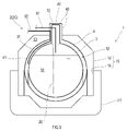
- FIG. 3 is a schematic cross-sectional view of a multi-shell tank 2A' to which the piping structure according to the first example is applied.
- the pipe penetration portion for the inter-tank pipe 92 is provided in the outer tank projecting portion 42.
- the inner tank protruding portion 32 has a collection of pipe penetration portions of pipes passed through the tower 20 including the inner tank pipe 91 .
- the outer tub projection 42 surrounds the inner tub projection 32 on the side, and the inner tub projection 32 and the outer tub projection 42 are sufficiently close to each other. Therefore, it can be said that the pipe penetration portion provided in the outer tank projection portion 42 and the pipe penetration portion of the inner tank projection portion 32 are collectively arranged in the multi-shell tanks 2A and 2A'.
- the piping structure as described above makes it possible to integrate a plurality of pipe penetrations of the multi-shell tanks 2A and 2A'.
- Each pipe penetration is airtightly constructed, heat-insulated, and reinforced, and strength evaluation is performed. Consolidation of pipe penetrations can be expected to improve workability.
- each pipe penetration and the valves and instruments installed in the pipes that pass through the pipe penetration are inspected during maintenance, but since the pipe penetration is consolidated, the maintenance points are concentrated. , can be expected to improve maintainability and accessibility.
- the inter-tank pipe 92 passes only through the cold insulation space 52 and does not pass through the storage space 51 and the holding space 53. Therefore, even if the fluid passing through the inter-tank pipe 92 leaks into the cold insulation space 52 or the exposure in the unlikely event that the inter-tank pipe 92 is damaged, it will not leak into the storage space 51 and the holding space 53 . Therefore, when the fluid passing through the inter-tank pipe 92 is combustible gas, the above pipe structure is particularly useful.
- FIG. 4 is a schematic cross-sectional view of a multi-shell tank 2B to which the piping structure according to the second example is applied.
- the inner tank projecting portion 32 has a constricted portion 33 between a base portion 35 and a top portion 36 which are connected to the inner tank main body 31 in the vertical direction.
- the constricted portion 33 has a smaller diameter than the top portion 36 and the base portion 35 of the inner tank projecting portion 32 .
- the constricted portion 33 may be provided over the entire outer periphery of the inner tank protruding portion 32 , or may be provided at a plurality of locations distributed around the outer periphery of the inner tank protruding portion 32 .
- the outer tub 4 has an outer tub main body 41 and an outer tub projecting portion 42 projecting upward from the top of the outer tub main body 41 .
- the outer tank projecting portion 42 has a tubular shape surrounding the constricted portion 33 of the inner tank projecting portion 32 .
- the outer diameter of the outer tank projecting portion 42 is substantially the same as the outer diameter of the top portion 36 of the inner tank projecting portion 32, and the constricted portion 33 of the inner tank projecting portion 32 and the outer tank projecting portion 42 are separated from each other. is doing.
- the outer diameter of the outer tub protruding portion 42 and the outer diameter of the top portion 36 of the inner tub protruding portion 32 may be different.
- a part of the side portion of the outer tank projecting portion 42 is an outer tank exposed portion 43 that is exposed above the tank cover 12 .
- the inter-tank pipe 92 is passed between the inner tank main body 31 and the outer tank main body 41 and between the constricted part 33 of the inner tank protruding part 32 and the outer tank protruding part 42 to extend between the outer tank protruding part 42. It extends outside through the outer tub exposure portion 43 .
- a pipe penetration portion for the inter-tank pipe 92 is provided in the outer-tank exposed portion 43 on the side of the outer-tank projecting portion 42 .
- the inter-tank pipe 92 passes through only the cold insulation space 52 in the multi-shell tank 2B, and does not pass through the storage space 51 and the holding space 53 .
- the multi-shell tank 2B having the piping structure according to the second example has the following effects in addition to the effects of the multi-shell tanks 2A and 2A' having the piping structure according to the first example. That is, the combined volume of the outer tank projecting part 42 and the inner tank projecting part 32 can be suppressed while each of the outer tank projecting part 42 and the inner tank projecting part 32 has an independent exposure part.
- FIG. 5 is a schematic cross-sectional view of a multi-shell tank 2C to which the piping structure according to the third example is applied.
- the outer tank 4 has an outer tank main body 41 and an outer tank protruding portion 42 that protrudes upward from the top of the outer tank main body 41 .
- the outer tank projecting portion 42 has a dome shape that completely surrounds the inner tank projecting portion 32 .
- a top portion and a part of the side portion of the outer tank projecting portion 42 form an outer tank exposed portion 43 exposed above the tank cover 12 .
- the outer diameter of the outer tank projecting portion 42 is larger than the outer diameter of the inner tank projecting portion 32, and the inner tank projecting portion 32 and the outer tank projecting portion 42 are separated from each other.
- the inter-tank pipe 92 is passed between the inner tank main body 31 and the outer tank main body 41 and between the inner tank protruding part 32 and the outer tank protruding part 42, and is passed through the outer tank exposed part of the outer tank protruding part 42. 43 to extend to the outside.
- a pipe penetration portion for the inter-tank pipe 92 is provided in the outer-tank exposed portion 43 of the outer-tank projecting portion 42 .
- the pipe penetration portion is provided in the outer tank exposure portion 43 on the side of the outer tank projection portion 42, but the pipe penetration portion is provided in the outer tank exposure portion 43 on the top of the outer tank projection portion 42.
- the inter-tank pipe 92 passes only through the cold insulation space 52 in the multi-shell tank 2C, and does not pass through the storage space 51 and the holding space 53 .
- the multi-shell tank 2C having the piping structure according to the third example has the following effects in addition to the effects of the multi-shell tanks 2A, 2A having the piping structure according to the first example. That is, since the entire inner tank protrusion 32 is covered with the outer tank protrusion 42 , a cold insulating layer is formed around the entire inner tank protrusion 32 .
- FIG. 6 is a schematic cross-sectional view of a multi-shell tank 2D to which the piping structure according to the fourth example is applied.
- the outer tank 4 has an outer tank main body 41, and the outer tank main body 41 and the side surface of the inner tank projecting portion 32 are airtightly connected.
- the inter-tank pipe 92 is passed between the inner tank main body 31 and the outer tank main body 41, passes through the inner tank protruding part 32, passes through the inner tank protruding part 32, and passes through the exposed part of the inner tank protruding part 32. It penetrates and extends to the outside.
- the tube penetration part for the inter-tank pipe 92 is provided at the exposed part of the inner tank projecting part 32 to the cold insulation space 52 and the exposed part of the inner tank projecting part 32 .
- the pipe penetration part is provided in the outer tank exposure part 43 on the side surface of the inner tank protrusion part 32, but the pipe penetration part may be provided in the top exposed part of the inner tank protrusion part 32. .
- the pipe penetration portion for the inter-tank pipe 92 is provided in the inner tank projecting portion 32 . Furthermore, pipe penetration portions of pipes passed through the tower 20 including the inner tank pipe 91 are concentrated in the inner tank projecting portion 32 . In this manner, the pipe penetration portions of the pipes including the inter-tank pipe 92 are collectively arranged in the inner tank projecting portion 32 .
- the pipe structure as described above makes it possible to integrate a plurality of pipe penetrations of the multi-shell tank 2D.
- Each pipe penetration is airtightly constructed, heat-insulated, and reinforced, and strength evaluation is performed. Consolidation of pipe penetrations can be expected to improve workability.
- each pipe penetration and the valves and instruments installed in the pipes that pass through the pipe penetration are inspected during maintenance, but since the pipe penetration is consolidated, the maintenance points are concentrated. , can be expected to improve maintainability and accessibility.
- the inter-tank pipe 92 passes through the cold insulation space 52 and the storage space 51 but does not pass through the holding space 53 . Therefore, even if the inter-tank pipe 92 is damaged and the fluid passing through the inter-tank pipe 92 leaks into the storage space 51 , the cold insulation space 52 or the exposure, it does not leak into the holding space 53 . Therefore, when the fluid passing through the inter-tank pipe 92 is the same as the vaporized gas of the liquefied gas contained in the storage space 51, the above pipe structure is particularly useful.
- FIG. 7 is a schematic cross-sectional view of a multi-shell tank 2E to which the piping structure according to the fifth example is applied.
- the inner tank 3 has an inner tank main body 31 and does not have an inner tank projecting portion 32.
- the outer tub 4 has an outer tub main body 41 and an outer tub projecting portion 42 projecting upward from the top of the outer tub main body 41 .
- the outer tub projecting portion 42 has a dome shape. A top portion and a part of the side portion of the outer tank projecting portion 42 form an outer tank exposed portion 43 exposed to the outside of the tank cover 12 .
- the inter-tank pipe 92 passes between the inner tank main body 31 and the outer tank main body 41 and the inside of the outer tank protruding portion 42, penetrates the outer tank exposing portion 43 of the outer tank protruding portion 42, and extends to the outside. is served.
- the pipe penetration portion for the inter-tank pipe 92 is provided in the outer tank exposed portion 43 on the side of the outer tank projecting portion 42, but the pipe penetration portion for the inter-tank pipe 92 is It may be provided in the outer tank exposure portion 43 at the top of the projecting portion 42 .
- the inter-tank pipe 92 passes only through the cold insulation space 52 in the multi-shell tank 2E, and does not pass through the storage space 51 and the holding space 53 .
- the inner tank pipe 91 penetrates the inner tank main body 31, passes through the inside of the outer tank projecting portion 42, penetrates the outer tank exposed portion 43 of the outer tank projecting portion 42, and extends to the outside.
- the pipe penetration portion for the inner tank pipe 91 is provided in the outer tank exposed portion 43 at the top of the outer tank protrusion 42, but the pipe penetration portion for the inner tank pipe 91 protrudes from the outer tank. It may be provided in the outer tub exposure portion 43 on the side of the portion 42 .
- the inner tank pipe 91 passes through the storage space 51 and the cold insulation space 52 in the multi-shell tank 2E, but does not pass through the holding space 53.
- the multi-shell tank 2E having the piping structure according to the fifth example even if the inter-tank piping 92 is damaged, even if the fluid passing through the inter-tank piping 92 leaks into the cold insulation space 52 or the exposure, It does not leak into the space 53 .
- the inner tank pipe 91 is damaged or the like, even if the fluid passing through the inner tank pipe 91 leaks into the storage space 51, the cold insulation space 52, or the exposure, it will not leak into the holding space 53. . Therefore, when the fluid filled in the cold insulation space 52 is the same as the vaporized gas of the liquefied gas stored in the storage space 51, the above piping structure is particularly useful.
- the multi-shell tanks 2A, 2A', 2B, and 2C having the piping structures according to the first to third examples of the present embodiment include the inner tank 3 and the outer tank 4 containing the inner tank 3. , an outermost shell 15 accommodating the inner tank 3 and the outer tank 4, and an inter-tank pipe 92 passing between the inner tank 3 and the outer tank 4.
- the inner tank 3 has an inner tank main body 31 and an inner tank protruding portion 32 protruding outside the outermost shell 15 from the top of the inner tank main body 31 through the outermost shell 15 .
- the outer tank 4 includes an outer tank main body 41 covering an inner tank main body 31 , and a top portion of the outer tank main body 41 penetrating the outermost shell 15 and projecting to the outside of the outermost shell 15 . and a surrounding outer bath protrusion 42, the outer bath protrusion 42 having an exposed outer bath exposed portion 43 at least in part.
- the inter-tank pipe 92 passes between the inner tank main body 31 and the outer tank main body 41, passes between the inner tank protruding part 32 and the outer tank protruding part 42, and extends between the outer tank protruding part 42. It extends outward through the outer tub exposed portion 43 .
- the pipe penetration part for the inter-tank pipe 92 is provided in the outer tank exposed part 43 of the outer tank projecting part 42.
- the outer tank projecting portion 42 surrounds the inner tank projecting portion 32 in which the pipe penetration portions of the pipes passed through the inner tank 3 are concentrated, and the pipe penetration portion of the inter-tank pipe 92 passes through the inner tank 3. It is placed close to the pipe penetration part of the installed pipe.
- the inter-tank pipe 92 passes only through the cold insulation space 52 and does not pass through the storage space 51 and the holding space 53. Therefore, even if the inter-tank pipe 92 is damaged, the fluid passing through the inter-tank pipe 92 does not leak into the storage space 51 and the holding space 53 . Therefore, when the fluid passing through the inter-tank pipe 92 is combustible gas as in the above embodiment, the above pipe structure is particularly useful because the combustible gas can be prevented from flowing out to the holding space 53 .
- the inner tank projecting portion 32 projects more than the outer tank projecting portion 42, and the outer tank projecting portion 42 protrudes from the top and side portions. At least one side has an outer tub exposure portion 43 .
- the inner tank projecting portion 32 has a constricted portion 33 in the middle of the projecting direction, and the outer tank projecting portion 42 surrounds the constricted portion 33.
- the inter-tank pipe 92 is passed between the constricted portion 33 of the inner tank projecting portion 32 and the outer tank projecting portion 42 .
- a multi-shell tank 2D having a piping structure includes an inner tank 3, an outer tank 4 containing the inner tank 3, and an outermost shell containing the inner tank 3 and the outer tank 4. 15 and an inter-tank pipe 92 passing between the inner tank 3 and the outer tank 4 .
- the inner tank 3 has an inner tank main body 31 and an inner tank projecting portion 32 projecting from the top of the inner tank main body 31 through the outer tank 4 and the outermost shell 15 to the outside of the outermost shell 15 .
- At least a portion of the inner bath protruding portion 32 has an exposed inner bath exposed portion 38 .
- the outer tub 4 has an outer tub body 41 that covers the inner tub body 31 .
- the inter-tank pipe 92 is passed between the inner tank main body 31 and the outer tank main body 41, passes through the inner tank protruding part 32, passes into the inner tank protruding part 32, and extends through the inner tank protruding part 32. It extends outward through the inner bath exposed portion 38 .
- the pipe penetration portion for the inter-tank pipe 92 is provided in the inner tank projection portion 32, so that the pipe penetration portion of the pipe including the inter-tank pipe 92 is integrated into the inner tank projection portion 32.
- the inter-tank pipe 92 passes through the cold insulation space 52 and the storage space 51, but does not pass through the holding space 53. Therefore, in the unlikely event that the inter-tank pipe 92 is damaged, the fluid passing through the inter-tank pipe 92 is prevented from leaking into the holding space 53 . Therefore, when the fluid passing through the inter-tank pipe 92 is the same combustible gas as the vaporized gas of the liquefied gas contained in the storage space 51, the combustible gas can be prevented from flowing out to the holding space 53.
- the piping construction described above is particularly useful.
- a multi-shell tank 2E having a piping structure according to the fifth example of the present embodiment includes an inner tank 3, an outer tank 4 containing the inner tank 3, and an outermost shell containing the inner tank 3 and the outer tank 4. 15, an inter-tank pipe 92 passing between the inner tank 3 and the outer tank 4, and an inner tank pipe 91 for communicating the inside of the inner tank 3 with the outside.
- the inner tank 3 has an inner tank main body 31
- the outer tank 4 includes an outer tank main body 41 covering the inner tank main body 31 and an outermost shell 15 extending from the outer tank main body 41 through the outermost shell 15.
- the outer tank projecting part 42 has an outer tank exposed part 43 exposed to the outside of the outermost shell 15 at least in part.
- the inter-tank pipe 92 passes between the inner tank main body 31 and the outer tank main body 41, passes through the inside of the outer tank protruding portion 42, passes through the outer tank exposing portion 43 of the outer tank protruding portion 42, and extends to the outside.
- the inner tank pipe 91 extends from the inner tank main body 31 through the inner tank main body 31, passes through the inside of the outer tank projecting portion 42, and penetrates the outer tank exposed portion 43 of the outer tank projecting portion 42. extended outwards.
- the pipe penetration portion for the inter-tank pipe 92 and the inner-tank pipe 91 is provided in the outer-tank projecting portion 42, so that the inter-tank pipe 92 and the inner-tank pipe are connected to the outer-tank projecting portion 42.
- the pipe penetration portions of the pipes including 91 are collectively arranged.
- the inter-tank pipe 92 passes through the cold insulation space 52 and does not pass through the holding space 53.
- the inner tank pipe 91 passes through the storage space 51 and the cold insulation space 52 and does not pass through the holding space 53 . Therefore, even if the inter-tank pipe 92 and/or the inner-tank pipe 91 should be damaged, the fluid passing through the inter-tank pipe 92 and/or the inner-tank pipe 91 is prevented from leaking into the holding space 53. . Therefore, when the fluid filled in the cold insulation space 52 is the same as the vaporized gas of the liquefied gas stored in the storage space 51, the above piping structure is particularly useful.
- the ship 1 includes a hull 11 and multi-hull tanks 2 (2A to 2E) supported by the hull 11.
- a liquefied gas is stored in the inner tank 3, a combustible gas is filled between the inner tank 3 and the outer tank 4, and a non-flammable gas, a flame-retardant gas, or , filled with dry air.
- the combustible gas filled between the inner tank 3 and the outer tank 4 flows through the inter-tank pipe 92 between the outer tank 4 and the outermost shell 15. is prevented from leaking into the space filled with the nonflammable gas between.
- the multi-shell tank 2 (2A to 2E) includes two tanks, an inner tank 3 and an outer tank 4, but may include three or more tanks.
- the present disclosure can be applied by regarding a set of tubs adjacent inside and outside as an inner tub 3 and an outer tub 4 .
- the multi-shell tanks 2 (2A to 2E) according to the above embodiment are spherical (or rectangular) tanks independent of the hull 11, but they may be membrane tanks using the hull 11.
- the present disclosure can be applied to a membrane tank by replacing the inner tank 3 with the membrane, the outer tank 4 with the inner shell, and the outermost shell 15 with the outer shell (hull) in the above embodiment.
- the multi-shell tanks 2 (2A to 2E) according to the above embodiment are cargo tanks, but the multi-shell tanks 2 (2A to 2E) do not necessarily have to be mounted on the ship 1 as cargo tanks, and can be used as fuel tanks. may be installed. Also, the number of multi-shell tanks 2 (2A to 2E) mounted on the ship 1 is not specified.
Landscapes
- Engineering & Computer Science (AREA)
- Mechanical Engineering (AREA)
- General Engineering & Computer Science (AREA)
- Chemical & Material Sciences (AREA)
- Combustion & Propulsion (AREA)
- Ocean & Marine Engineering (AREA)
- Physics & Mathematics (AREA)
- Thermal Sciences (AREA)
- Filling Or Discharging Of Gas Storage Vessels (AREA)
Abstract
Description
内槽と、前記内槽を収容した外槽と、前記内槽及び前記外槽を収容した最外殻と、前記内槽と前記外槽との間を通された槽間配管とを備え、
前記内槽は、内槽本体と、前記内槽本体から前記最外殻を貫いて当該最外殻の外側へ突出した内槽突出部とを有し、
前記外槽は、前記内槽本体を覆う外槽本体と、前記最外殻を貫いて当該最外殻の外側へ突出し且つ前記内槽突出部の少なくとも一部分を包囲する外槽突出部とを有し、
前記外槽突出部は前記最外殻の外側に露出した外槽曝露部を少なくとも一部分に有し、
前記槽間配管は、前記内槽本体と前記外槽本体との間を通され、前記内槽突出部と前記外槽突出部との間を通され、且つ、前記外槽突出部の前記外槽曝露部を貫いて外側へ延出されていることを特徴としている。 A multi-shell tank according to the present disclosure includes:
An inner tank, an outer tank containing the inner tank, an outermost shell containing the inner tank and the outer tank, and an inter-tank pipe passing between the inner tank and the outer tank,
The inner tank has an inner tank main body and an inner tank protruding portion projecting from the inner tank main body through the outermost shell to the outside of the outermost shell,
The outer tank has an outer tank main body that covers the inner tank main body, and an outer tank protrusion that penetrates the outermost shell and protrudes to the outside of the outermost shell and surrounds at least a portion of the inner tank protrusion. death,
The outer tank protruding part has at least a part thereof exposed to the outside of the outermost shell,
The inter-tank pipe passes between the inner tank main body and the outer tank main body, passes between the inner tank protruding portion and the outer tank protruding portion, and extends from the outer tank protruding portion to the outside of the outer tank protruding portion. It is characterized by extending outward through the bath exposed portion.
内槽と、前記内槽を収容した外槽と、前記内槽及び前記外槽を収容した最外殻と、前記内槽と前記外槽との間を通された槽間配管とを備え、
前記内槽は、内槽本体と、前記内槽本体から前記外槽及び前記最外殻を貫いて当該最外殻の外側へ突出した内槽突出部とを有し、
前記外槽は、前記内槽本体を覆う外槽本体を有し、
前記内槽突出部は前記最外殻の外側に露出した内槽曝露部を少なくとも一部分に有し、
前記槽間配管は、前記内槽本体と前記外槽本体との間を通され、前記内槽突出部を貫いて前記内槽突出部内へ通され、且つ、前記内槽突出部の前記内槽曝露部を貫いて外側へ延出されていることを特徴としている。 In addition, the multi-shell tank according to the present disclosure is
An inner tank, an outer tank containing the inner tank, an outermost shell containing the inner tank and the outer tank, and an inter-tank pipe passing between the inner tank and the outer tank,
The inner tank has an inner tank main body and an inner tank protruding portion projecting from the inner tank main body through the outer tank and the outermost shell to the outside of the outermost shell,
The outer tank has an outer tank body covering the inner tank body,
The inner tank protruding part has at least a part of an inner tank exposed part exposed to the outside of the outermost shell,
The inter-tank pipe is passed between the inner tank main body and the outer tank main body, passes through the inner tank protruding part and into the inner tank protruding part, and is connected to the inner tank protruding part. It is characterized by extending outward through the exposed portion.
内槽と、前記内槽を収容した外槽と、前記内槽及び前記外槽を収容した最外殻と、前記内槽と前記外槽との間を通された槽間配管と、前記内槽内を外部と連通させる内槽配管とを備え、
前記内槽は、内槽本体を有し、
前記外槽は、前記内槽本体を覆う外槽本体と、前記外槽本体から前記最外殻を貫いて当該最外殻の外側へ突出した外槽突出部とを有し、
前記外槽突出部は前記最外殻の外側に露出した外槽曝露部を少なくとも一部分に有し、
前記槽間配管は、前記内槽本体と前記外槽本体との間を通され、前記外槽突出部の内部を通され、前記外槽突出部の前記外槽曝露部を貫いて外側へ延出され、
前記内槽配管は、前記内槽本体内から前記内槽本体を貫いて、前記外槽突出部の内部を通され、前記外槽突出部の前記外槽曝露部を貫いて外側へ延出されていることを特徴としている。 In addition, the multi-shell tank according to the present disclosure is
an inner tank, an outer tank containing the inner tank, an outermost shell containing the inner tank and the outer tank, an inter-tank pipe passing between the inner tank and the outer tank, and the inner tank Equipped with an inner tank pipe that communicates the inside of the tank with the outside,
The inner tank has an inner tank body,
The outer tank has an outer tank main body that covers the inner tank main body, and an outer tank protruding portion that penetrates the outermost shell from the outer tank main body and protrudes to the outside of the outermost shell,
The outer tank protruding part has at least a part thereof exposed to the outside of the outermost shell,
The inter-tank pipe passes between the inner tank main body and the outer tank main body, passes through the inside of the outer tank protruding part, penetrates the outer tank exposed part of the outer tank protruding part, and extends to the outside. served,
The inner tank pipe passes through the inner tank main body from within the inner tank main body, passes through the inside of the outer tank protruding portion, and extends outward through the outer tank exposed portion of the outer tank protruding portion. It is characterized by
図1は、本実施形態に係る多重殻タンク2を備えた船舶1の概略側面図である。図1に示すように、船舶1は、少なくとも1つの多重殻タンク2と、多重殻タンク2を搭載した船体11とを備える。船舶1は、低温の液化ガスを運搬する液化ガス運搬船である。液化ガスとして、LNG、液化窒素、液化水素、液化ヘリウムなどが例示される。 [Schematic configuration of ship 1]
FIG. 1 is a schematic side view of a
図2は、第1例に係る配管構造が適用された多重殻タンク2(2A)の概略断面図である。図1及び図2に示すように、多重殻タンク2は、内槽3と、内槽3を収容した外槽4と、内槽3及び外槽4を収容した最外殻15とを備える。本実施形態に係る最外殻15は、外槽4の上部を覆うタンクカバー12及び外槽4の側部及び底部を覆う保持壁14により形成されている。タンクカバー12に代えて船体11の一部によって外槽4の上部が覆われていてもよい。保持壁14は、例えば船体11の一部により形成されていてよい。 [Schematic configuration of multi-shell tank 2]
FIG. 2 is a schematic cross-sectional view of a multi-shell tank 2 (2A) to which the piping structure according to the first example is applied. As shown in FIGS. 1 and 2 , the
以下、多重殻タンク2に主に槽間配管92を配管するための配管構造の第1~5例について説明する。 [Piping structure]
First to fifth examples of the piping structure for mainly connecting the
図2に示す多重殻タンク2Aにおいて、外槽4は、外槽本体41と、外槽本体41の頂部から上方へ向けて突出した外槽突出部42とを有する。外槽突出部42は、内槽3と外槽4との間の保冷空間52を通された配管を他の空間を通さずに直接的に曝露へ導くために、タンクカバー12よりも上方の曝露空間へ向けて突出し且つ保冷空間52と連通された空間を形成するためのものである。 <First example of piping structure>
In the
図4は、第2例に係る配管構造が適用された多重殻タンク2Bの概略断面図である。図4に示す多重殻タンク2Bにおいて、内槽突出部32は、内槽本体31との接続部である基部35と頂部36との上下方向の間に括れ部33を有する。括れ部33は、内槽突出部32の頂部36及び基部35よりも小径である。括れ部33は、内槽突出部32の全外周に亘って設けられていてもよいし、内槽突出部32の外周に分散して複数箇所設けられていてもよい。 <Second example of piping structure>
FIG. 4 is a schematic cross-sectional view of a
図5は、第3例に係る配管構造が適用された多重殻タンク2Cの概略断面図である。図5に示す多重殻タンク2Cにおいて、外槽4は、外槽本体41と、外槽本体41の頂部から上方へ向けて突出した外槽突出部42とを有する。外槽突出部42は、内槽突出部32の全体をすっぽりと包囲するドーム形状を呈する。外槽突出部42の頂部と側部の一部は、タンクカバー12よりも上方に露出した外槽曝露部43となっている。外槽突出部42の外径は内槽突出部32の外径よりも大きく、内槽突出部32と外槽突出部42との間は離間している。 <Third example of piping structure>
FIG. 5 is a schematic cross-sectional view of a
図6は、第4例に係る配管構造が適用された多重殻タンク2Dの概略断面図である。図6に示す多重殻タンク2Dにおいて、外槽4は、外槽本体41を有し、外槽本体41と内槽突出部32の側面とが気密に接続されている。 <Fourth example of piping structure>
FIG. 6 is a schematic cross-sectional view of a
図7は、第5例に係る配管構造が適用された多重殻タンク2Eの概略断面図である。図7に示す多重殻タンク2Eにおいて、内槽3は内槽本体31を有し、内槽突出部32を有しない。外槽4は、外槽本体41と、外槽本体41の頂部から上方へ向けて突出した外槽突出部42とを有する。外槽突出部42は、ドーム形状を呈する。外槽突出部42の頂部と側部の一部は、タンクカバー12の外側に露出した外槽曝露部43となっている。 <Fifth example of piping structure>
FIG. 7 is a schematic cross-sectional view of a
以上に説明したように、本実施形態の第1~3例に係る配管構造を備える多重殻タンク2A,2A’,2B,2Cは、内槽3と、内槽3を収容した外槽4と、内槽3及び外槽4を収容した最外殻15と、内槽3と外槽4との間を通された槽間配管92とを備える。ここで、内槽3は、内槽本体31と、内槽本体31の頂部から最外殻15を貫いて当該最外殻15の外側へ突出した内槽突出部32とを有する。外槽4は、内槽本体31を覆う外槽本体41と、外槽本体41の頂部から最外殻15を貫いて当該最外殻15の外側へ突出し且つ内槽突出部32の少なくとも一部分を包囲する外槽突出部42とを有し、外槽突出部42は曝露された外槽曝露部43を少なくとも一部分に有する。そして、槽間配管92は、内槽本体31と外槽本体41との間を通され、内槽突出部32と外槽突出部42との間を通され、且つ、外槽突出部42の外槽曝露部43を貫いて外側へ延出されている。 [Summary]
As described above, the
Claims (7)
- 内槽と、前記内槽を収容した外槽と、前記内槽及び前記外槽を収容した最外殻と、前記内槽と前記外槽との間を通された槽間配管とを備え、
前記内槽は、内槽本体と、前記内槽本体から前記最外殻を貫いて当該最外殻の外側へ突出した内槽突出部とを有し、
前記外槽は、前記内槽本体を覆う外槽本体と、前記最外殻を貫いて当該最外殻の外側へ突出し且つ前記内槽突出部の少なくとも一部分を包囲する外槽突出部とを有し、
前記外槽突出部は前記最外殻の外側に露出した外槽曝露部を少なくとも一部分に有し、
前記槽間配管は、前記内槽本体と前記外槽本体との間を通され、前記内槽突出部と前記外槽突出部との間を通され、且つ、前記外槽突出部の前記外槽曝露部を貫いて外側へ延出されている、
多重殻タンク。 An inner tank, an outer tank containing the inner tank, an outermost shell containing the inner tank and the outer tank, and an inter-tank pipe passing between the inner tank and the outer tank,
The inner tank has an inner tank main body and an inner tank protruding portion projecting from the inner tank main body through the outermost shell to the outside of the outermost shell,
The outer tank has an outer tank main body that covers the inner tank main body, and an outer tank protrusion that penetrates the outermost shell and protrudes to the outside of the outermost shell and surrounds at least a portion of the inner tank protrusion. death,
The outer tank protruding part has at least a part thereof exposed to the outside of the outermost shell,
The inter-tank pipe passes between the inner tank main body and the outer tank main body, passes between the inner tank protruding portion and the outer tank protruding portion, and extends from the outer tank protruding portion to the outside of the outer tank protruding portion. extending outwardly through the bath exposure portion;
Multi-shell tank. - 前記内槽突出部は前記外槽突出部より大きく突出しており、前記外槽突出部はその頂部及び側部のうち少なくとも一方に前記外槽曝露部を有する、
請求項1に記載の多重殻タンク。 The inner tank protruding part protrudes larger than the outer tank protruding part, and the outer tank protruding part has the outer tank exposed part on at least one of its top part and side part,
A multi-shell tank according to claim 1. - 前記内槽突出部は突出方向の中途部に括れ部を有し、
前記外槽突出部は前記括れ部を包囲しており、
前記槽間配管は前記内槽突出部の前記括れ部と前記外槽突出部との間を通されている、請求項1に記載の多重殻タンク。 The inner tank protruding part has a constricted part in the middle part of the protruding direction,
The outer tank projecting portion surrounds the constricted portion,
2. The multi-shell tank according to claim 1, wherein said inter-tank pipe is passed between said constricted portion of said inner tank projecting portion and said outer tank projecting portion. - 内槽と、前記内槽を収容した外槽と、前記内槽及び前記外槽を収容した最外殻と、前記内槽と前記外槽との間を通された槽間配管とを備え、
前記内槽は、内槽本体と、前記内槽本体から前記外槽及び前記最外殻を貫いて当該最外殻の外側へ突出した内槽突出部とを有し、
前記外槽は、前記内槽本体を覆う外槽本体を有し、
前記内槽突出部は前記最外殻の外側に露出した内槽曝露部を少なくとも一部分に有し、
前記槽間配管は、前記内槽本体と前記外槽本体との間を通され、前記内槽突出部を貫いて前記内槽突出部内へ通され、且つ、前記内槽突出部の前記内槽曝露部を貫いて外側へ延出されている、
多重殻タンク。 An inner tank, an outer tank containing the inner tank, an outermost shell containing the inner tank and the outer tank, and an inter-tank pipe passing between the inner tank and the outer tank,
The inner tank has an inner tank main body and an inner tank protruding portion projecting from the inner tank main body through the outer tank and the outermost shell to the outside of the outermost shell,
The outer tank has an outer tank body covering the inner tank body,
The inner tank protruding part has at least a part of an inner tank exposed part exposed to the outside of the outermost shell,
The inter-tank pipe is passed between the inner tank main body and the outer tank main body, passes through the inner tank protruding part and into the inner tank protruding part, and is connected to the inner tank protruding part. extending outwardly through the exposed portion,
Multi-shell tank. - 内槽と、前記内槽を収容した外槽と、前記内槽及び前記外槽を収容した最外殻と、前記内槽と前記外槽との間を通された槽間配管と、前記内槽内を外部と連通させる内槽配管とを備え、
前記内槽は、内槽本体を有し、
前記外槽は、前記内槽本体を覆う外槽本体と、前記外槽本体から前記最外殻を貫いて当該最外殻の外側へ突出した外槽突出部とを有し、
前記外槽突出部は前記最外殻の外側に露出した外槽曝露部を少なくとも一部分に有し、
前記槽間配管は、前記内槽本体と前記外槽本体との間を通され、前記外槽突出部の内部を通され、前記外槽突出部の前記外槽曝露部を貫いて外側へ延出され、
前記内槽配管は、前記内槽本体内から前記内槽本体を貫いて、前記外槽突出部の内部を通され、前記外槽突出部の前記外槽曝露部を貫いて外側へ延出されている、
多重殻タンク。 an inner tank, an outer tank containing the inner tank, an outermost shell containing the inner tank and the outer tank, an inter-tank pipe passing between the inner tank and the outer tank, and the inner tank Equipped with an inner tank pipe that communicates the inside of the tank with the outside,
The inner tank has an inner tank body,
The outer tank has an outer tank main body that covers the inner tank main body, and an outer tank protruding portion that penetrates the outermost shell from the outer tank main body and protrudes to the outside of the outermost shell,
The outer tank protruding part has at least a part thereof exposed to the outside of the outermost shell,
The inter-tank pipe passes between the inner tank main body and the outer tank main body, passes through the inside of the outer tank protruding part, penetrates the outer tank exposed part of the outer tank protruding part, and extends to the outside. served,
The inner tank pipe passes through the inner tank main body from within the inner tank main body, passes through the inside of the outer tank protruding portion, and extends outward through the outer tank exposed portion of the outer tank protruding portion. ing,
Multi-shell tank. - 船体と、
前記船体に支持された請求項1~5のいずれか一項に記載の多重殻タンクとを備える、船舶。 a hull;
A ship comprising a multi-hull tank according to any one of claims 1 to 5 supported by said hull. - 前記内槽に液化ガスが収容され、前記内槽と前記外槽との間に可燃性ガスが充填され、前記外槽と前記最外殻との間に不燃性ガス、難燃性ガス、又は、乾燥空気が充填されている、
請求項6に記載の船舶。 A liquefied gas is contained in the inner tank, a combustible gas is filled between the inner tank and the outer tank, and a non-flammable gas, a flame-retardant gas, or , filled with dry air,
A vessel according to claim 6.
Priority Applications (3)
| Application Number | Priority Date | Filing Date | Title |
|---|---|---|---|
| EP22781046.2A EP4317764A1 (en) | 2021-03-31 | 2022-03-30 | Multi-shell tank and vessel |
| KR1020237031858A KR20230147673A (en) | 2021-03-31 | 2022-03-30 | Multi-angle tanks and ships |
| CN202280026284.4A CN117120766A (en) | 2021-03-31 | 2022-03-30 | Multi-layer shell tank and ship |
Applications Claiming Priority (2)
| Application Number | Priority Date | Filing Date | Title |
|---|---|---|---|
| JP2021061365A JP2022157248A (en) | 2021-03-31 | 2021-03-31 | Multi-shell tank and vessel |
| JP2021-061365 | 2021-03-31 |
Publications (1)
| Publication Number | Publication Date |
|---|---|
| WO2022210835A1 true WO2022210835A1 (en) | 2022-10-06 |
Family
ID=83456476
Family Applications (1)
| Application Number | Title | Priority Date | Filing Date |
|---|---|---|---|
| PCT/JP2022/015825 WO2022210835A1 (en) | 2021-03-31 | 2022-03-30 | Multi-shell tank and vessel |
Country Status (5)
| Country | Link |
|---|---|
| EP (1) | EP4317764A1 (en) |
| JP (1) | JP2022157248A (en) |
| KR (1) | KR20230147673A (en) |
| CN (1) | CN117120766A (en) |
| WO (1) | WO2022210835A1 (en) |
Citations (5)
| Publication number | Priority date | Publication date | Assignee | Title |
|---|---|---|---|---|
| JPS5997397A (en) * | 1982-11-26 | 1984-06-05 | Kawaju Koji Kk | Double shell low temperature tank insulation material re-filling method and device |
| JPH06323498A (en) | 1993-05-14 | 1994-11-25 | Ishikawajima Harima Heavy Ind Co Ltd | Liquid gas storage device and carrying vessel thereof |
| JP2015004383A (en) * | 2013-06-19 | 2015-01-08 | 川崎重工業株式会社 | Double shell tank and liquefied gas carrying vessel |
| JP2019157868A (en) * | 2018-03-07 | 2019-09-19 | 川崎重工業株式会社 | Liquefied gas tank |
| JP2020104787A (en) * | 2018-12-28 | 2020-07-09 | 川崎重工業株式会社 | Vessel |
-
2021
- 2021-03-31 JP JP2021061365A patent/JP2022157248A/en active Pending
-
2022
- 2022-03-30 CN CN202280026284.4A patent/CN117120766A/en active Pending
- 2022-03-30 EP EP22781046.2A patent/EP4317764A1/en active Pending
- 2022-03-30 KR KR1020237031858A patent/KR20230147673A/en unknown
- 2022-03-30 WO PCT/JP2022/015825 patent/WO2022210835A1/en active Application Filing
Patent Citations (5)
| Publication number | Priority date | Publication date | Assignee | Title |
|---|---|---|---|---|
| JPS5997397A (en) * | 1982-11-26 | 1984-06-05 | Kawaju Koji Kk | Double shell low temperature tank insulation material re-filling method and device |
| JPH06323498A (en) | 1993-05-14 | 1994-11-25 | Ishikawajima Harima Heavy Ind Co Ltd | Liquid gas storage device and carrying vessel thereof |
| JP2015004383A (en) * | 2013-06-19 | 2015-01-08 | 川崎重工業株式会社 | Double shell tank and liquefied gas carrying vessel |
| JP2019157868A (en) * | 2018-03-07 | 2019-09-19 | 川崎重工業株式会社 | Liquefied gas tank |
| JP2020104787A (en) * | 2018-12-28 | 2020-07-09 | 川崎重工業株式会社 | Vessel |
Also Published As
| Publication number | Publication date |
|---|---|
| EP4317764A1 (en) | 2024-02-07 |
| KR20230147673A (en) | 2023-10-23 |
| JP2022157248A (en) | 2022-10-14 |
| CN117120766A (en) | 2023-11-24 |
Similar Documents
| Publication | Publication Date | Title |
|---|---|---|
| FI122871B (en) | LNG containers | |
| JP7365400B2 (en) | Double shell tanks and liquefied gas carriers | |
| KR101871324B1 (en) | Double-shelled tank and liquefied gas transport vessel | |
| JP6466581B2 (en) | System for connecting at least one pipe between an LNG tank and its tank connection space | |
| EP3904196B1 (en) | Ship | |
| WO2022210835A1 (en) | Multi-shell tank and vessel | |
| CN113825942B (en) | Liquefied gas storage structure and liquefied gas carrier | |
| KR20210071318A (en) | Pump Tower of Liquefied Gas Storage Tank | |
| KR20210070163A (en) | liquefied gas tank, gas treatment system and ship having the same | |
| EP4129815A1 (en) | Ship | |
| KR20220149473A (en) | Storage facility for liquefied gas | |
| KR20210071317A (en) | Pump Tower of Liquefied Gas Storage Tank including Spraying Pipe | |
| KR20210071316A (en) | Cool-down Method of Liquefied Gas Storage Tank including Filling Pipe having Double Pipe Structure | |
| KR20210083419A (en) | Pump Tower Supporting Structure of Liquefied Gas Storage Tank | |
| KR20210082678A (en) | Pump Tower of Liquefied Gas Storage Tank | |
| KR20210070757A (en) | Pump Tower of Liquefied Gas Storage Tank including Filling Pipe having Double Pipe Structure | |
| KR20210082680A (en) | Pump Tower of Liquefied Gas Storage Tank | |
| WO2022210836A1 (en) | Double-hull tank and vessel | |
| WO2022145296A1 (en) | Triple-wall tank | |
| JP7161293B2 (en) | Double-hull tanks and liquefied gas carriers | |
| KR20210070756A (en) | Pump Tower Supporting Structure of Liquefied Gas Storage Tank | |
| CA3036925C (en) | A fuel tank unit | |
| KR20210083420A (en) | Pump Tower of Liquefied Gas Storage Tank | |
| KR20210083421A (en) | Pump Tower Supporting Structure of Liquefied Gas Storage Tank | |
| JP2024044539A (en) | Purge structure of flange connection and liquefied gas tank |
Legal Events
| Date | Code | Title | Description |
|---|---|---|---|
| 121 | Ep: the epo has been informed by wipo that ep was designated in this application |
Ref document number: 22781046 Country of ref document: EP Kind code of ref document: A1 |
|
| ENP | Entry into the national phase |
Ref document number: 20237031858 Country of ref document: KR Kind code of ref document: A |
|
| WWE | Wipo information: entry into national phase |
Ref document number: 1020237031858 Country of ref document: KR |
|
| WWE | Wipo information: entry into national phase |
Ref document number: 2022781046 Country of ref document: EP |
|
| ENP | Entry into the national phase |
Ref document number: 2022781046 Country of ref document: EP Effective date: 20231031 |
|
| NENP | Non-entry into the national phase |
Ref country code: DE |