WO2022210249A1 - 偏光子保護用ポリエステルフィルム、およびそれを用いた偏光板 - Google Patents
偏光子保護用ポリエステルフィルム、およびそれを用いた偏光板 Download PDFInfo
- Publication number
- WO2022210249A1 WO2022210249A1 PCT/JP2022/013909 JP2022013909W WO2022210249A1 WO 2022210249 A1 WO2022210249 A1 WO 2022210249A1 JP 2022013909 W JP2022013909 W JP 2022013909W WO 2022210249 A1 WO2022210249 A1 WO 2022210249A1
- Authority
- WO
- WIPO (PCT)
- Prior art keywords
- polarizer
- polyester film
- film
- less
- polarizing plate
- Prior art date
- Legal status (The legal status is an assumption and is not a legal conclusion. Google has not performed a legal analysis and makes no representation as to the accuracy of the status listed.)
- Ceased
Links
Images

Classifications
-
- C—CHEMISTRY; METALLURGY
- C08—ORGANIC MACROMOLECULAR COMPOUNDS; THEIR PREPARATION OR CHEMICAL WORKING-UP; COMPOSITIONS BASED THEREON
- C08J—WORKING-UP; GENERAL PROCESSES OF COMPOUNDING; AFTER-TREATMENT NOT COVERED BY SUBCLASSES C08B, C08C, C08F, C08G or C08H
- C08J5/00—Manufacture of articles or shaped materials containing macromolecular substances
- C08J5/18—Manufacture of films or sheets
-
- B—PERFORMING OPERATIONS; TRANSPORTING
- B32—LAYERED PRODUCTS
- B32B—LAYERED PRODUCTS, i.e. PRODUCTS BUILT-UP OF STRATA OF FLAT OR NON-FLAT, e.g. CELLULAR OR HONEYCOMB, FORM
- B32B27/00—Layered products comprising a layer of synthetic resin
- B32B27/36—Layered products comprising a layer of synthetic resin comprising polyesters
-
- B—PERFORMING OPERATIONS; TRANSPORTING
- B32—LAYERED PRODUCTS
- B32B—LAYERED PRODUCTS, i.e. PRODUCTS BUILT-UP OF STRATA OF FLAT OR NON-FLAT, e.g. CELLULAR OR HONEYCOMB, FORM
- B32B7/00—Layered products characterised by the relation between layers; Layered products characterised by the relative orientation of features between layers, or by the relative values of a measurable parameter between layers, i.e. products comprising layers having different physical, chemical or physicochemical properties; Layered products characterised by the interconnection of layers
- B32B7/02—Physical, chemical or physicochemical properties
- B32B7/023—Optical properties
-
- B—PERFORMING OPERATIONS; TRANSPORTING
- B32—LAYERED PRODUCTS
- B32B—LAYERED PRODUCTS, i.e. PRODUCTS BUILT-UP OF STRATA OF FLAT OR NON-FLAT, e.g. CELLULAR OR HONEYCOMB, FORM
- B32B7/00—Layered products characterised by the relation between layers; Layered products characterised by the relative orientation of features between layers, or by the relative values of a measurable parameter between layers, i.e. products comprising layers having different physical, chemical or physicochemical properties; Layered products characterised by the interconnection of layers
- B32B7/04—Interconnection of layers
- B32B7/12—Interconnection of layers using interposed adhesives or interposed materials with bonding properties
-
- C—CHEMISTRY; METALLURGY
- C08—ORGANIC MACROMOLECULAR COMPOUNDS; THEIR PREPARATION OR CHEMICAL WORKING-UP; COMPOSITIONS BASED THEREON
- C08G—MACROMOLECULAR COMPOUNDS OBTAINED OTHERWISE THAN BY REACTIONS ONLY INVOLVING UNSATURATED CARBON-TO-CARBON BONDS
- C08G63/00—Macromolecular compounds obtained by reactions forming a carboxylic ester link in the main chain of the macromolecule
- C08G63/02—Polyesters derived from hydroxycarboxylic acids or from polycarboxylic acids and polyhydroxy compounds
- C08G63/12—Polyesters derived from hydroxycarboxylic acids or from polycarboxylic acids and polyhydroxy compounds derived from polycarboxylic acids and polyhydroxy compounds
- C08G63/16—Dicarboxylic acids and dihydroxy compounds
- C08G63/18—Dicarboxylic acids and dihydroxy compounds the acids or hydroxy compounds containing carbocyclic rings
- C08G63/181—Acids containing aromatic rings
- C08G63/183—Terephthalic acids
-
- G—PHYSICS
- G02—OPTICS
- G02B—OPTICAL ELEMENTS, SYSTEMS OR APPARATUS
- G02B5/00—Optical elements other than lenses
- G02B5/30—Polarising elements
-
- G—PHYSICS
- G02—OPTICS
- G02B—OPTICAL ELEMENTS, SYSTEMS OR APPARATUS
- G02B5/00—Optical elements other than lenses
- G02B5/30—Polarising elements
- G02B5/3025—Polarisers, i.e. arrangements capable of producing a definite output polarisation state from an unpolarised input state
- G02B5/3033—Polarisers, i.e. arrangements capable of producing a definite output polarisation state from an unpolarised input state in the form of a thin sheet or foil, e.g. Polaroid
- G02B5/3041—Polarisers, i.e. arrangements capable of producing a definite output polarisation state from an unpolarised input state in the form of a thin sheet or foil, e.g. Polaroid comprising multiple thin layers, e.g. multilayer stacks
- G02B5/305—Polarisers, i.e. arrangements capable of producing a definite output polarisation state from an unpolarised input state in the form of a thin sheet or foil, e.g. Polaroid comprising multiple thin layers, e.g. multilayer stacks including organic materials, e.g. polymeric layers
-
- B—PERFORMING OPERATIONS; TRANSPORTING
- B32—LAYERED PRODUCTS
- B32B—LAYERED PRODUCTS, i.e. PRODUCTS BUILT-UP OF STRATA OF FLAT OR NON-FLAT, e.g. CELLULAR OR HONEYCOMB, FORM
- B32B2307/00—Properties of the layers or laminate
- B32B2307/40—Properties of the layers or laminate having particular optical properties
- B32B2307/42—Polarizing, birefringent, filtering
-
- C—CHEMISTRY; METALLURGY
- C08—ORGANIC MACROMOLECULAR COMPOUNDS; THEIR PREPARATION OR CHEMICAL WORKING-UP; COMPOSITIONS BASED THEREON
- C08J—WORKING-UP; GENERAL PROCESSES OF COMPOUNDING; AFTER-TREATMENT NOT COVERED BY SUBCLASSES C08B, C08C, C08F, C08G or C08H
- C08J2367/00—Characterised by the use of polyesters obtained by reactions forming a carboxylic ester link in the main chain; Derivatives of such polymers
- C08J2367/02—Polyesters derived from dicarboxylic acids and dihydroxy compounds
Definitions
- the present invention relates to a polarizer-protecting polyester film and a polarizing plate using the polarizer-protecting polyester film.
- a polarizing plate is often arranged on at least one side of a display cell in an image display device (for example, a liquid crystal display device, an organic EL display device) due to its image forming method.
- an image display device for example, a liquid crystal display device, an organic EL display device
- the functions and applications of image display devices have tended to diversify, and they are required to withstand use in harsher environments.
- a polarizing plate generally has a structure in which a polarizer is sandwiched between two protective films, and triacetyl cellulose, acrylic resins, cycloolefins, polyester resins, etc. are widely used as protective films.
- a polyester-based resin for example, polyethylene terephthalate (PET) is generally known to be excellent in durability, mechanical properties, chemical resistance, and water barrier properties.
- PET polyethylene terephthalate
- the film has such excellent mechanical properties, it has birefringence and has a problem of poor visibility such as iridescent unevenness.
- PEN polyethylene naphthalate
- an object of the present invention is to provide a polyester film for protecting a polarizer that does not cause iridescent unevenness when applied to an image display device and that can contribute to improving the durability of the polarizing plate against environmental changes, and polarized light using the same. It is to provide a board.
- the polyester film for protecting a polarizer according to (1) which has an in-plane retardation of 400 nm to 3000 nm.
- the polyester film for protecting a polarizer according to (1) or (2) wherein the thickness unevenness in the width direction of the film is 10% or less.
- the copolymerization component is 3 mol% or more and 25 mol% or less, and contains at least a component selected from adipic acid, isophthalic acid, and cyclohexanedimethanol, according to any one of (1) to (4).
- Polarizer protective polyester film (6)
- a polarizing plate comprising a polarizer and the polyester film according to any one of (1) to (7) arranged on one side of the polarizer.
- a polarizing plate to which the polyester film for protecting a polarizer of the present invention is applied does not generate iridescent unevenness even on a large screen when applied to an image display device, and the durability of the polarizing plate is improved even in environmental changes, that is, the polarizer Contributes to the suppression of cracks and provides clear images.
- the film thickness is thin, the curved surface followability and bending resistance are excellent, and therefore, it is suitable for curved surfaces, foldable displays, and rollable displays.
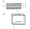
- FIG. 1 is a schematic diagram showing a preferred embodiment of the present invention
- FIG. 1 is a schematic diagram of an embodiment when the present invention is applied to an image display device
- FIG. 1 is a schematic diagram of an embodiment when the present invention is applied to an image display device
- polyester in the present invention has a main skeleton of polyethylene terephthalate obtained by a polymerization reaction of terephthalic acid as a main dicarboxylic acid component and ethylene glycol as a main diol component.
- the polyester in the present invention requires a dicarboxylic acid component of 75 mol% or more of terephthalic acid and a diol component of 75 mol% or more of ethylene glycol.
- terephthalic acid which is an aromatic dicarboxylic acid
- high heat resistance and crystallization are possible, so high thermal dimensional stability can be imparted.
- the linear thermal expansion coefficient can be reduced under environmental changes. If the content of terephthalic acid as a dicarboxylic acid component is less than 75 mol %, the amount of amorphous components increases and the thermal dimensional stability due to crystallization decreases.
- the content is preferably 80 mol% or more, more preferably 90 mol% or more.
- 100 mol % is the most preferable, but in that case, the inclusion of 3 mol % or more and 25 mol % or less of a copolymer component other than ethylene glycol as a diol component described later is the minimum refractive index and thickness in the in-plane direction. It is preferable from the viewpoint of the effect of suppressing rainbow unevenness in polarizer protection applications because the difference in refractive index between directions can be easily reduced.
- the ethylene glycol content of the diol component is less than 75 mol %, the amorphous component increases and the high thermal dimensional stability due to crystallization decreases. More preferably, it is 80 mol % or more, and still more preferably 90 mol % or more. 100 mol % is the most preferable, but in that case, the inclusion of 3 mol % or more and 25 mol % or less of a copolymer component other than terephthalic acid is necessary to achieve the minimum refractive index in the in-plane direction and the refractive index in the thickness direction. It is easy to reduce the difference, and is preferable from the viewpoint of the effect of suppressing rainbow unevenness in polarizer protection applications.
- dicarboxylic acid component of the copolymerization component examples include aromatic dicarboxylic acids such as isophthalic acid and phthalic acid, and aliphatic dicarboxylic acids such as adipic acid, suberic acid, sebacic acid, dimer acid, dodecanedioic acid, and cyclohexane. dicarboxylic acids and their ester derivatives; Among them, adipic acid and isophthalic acid are preferable from the viewpoint of high refractive index and easy uniaxial orientation. These acid components may be used alone, or two or more of them may be used in combination. Further, oxyacids such as hydroxybenzoic acid may be partially copolymerized.
- aromatic dicarboxylic acids such as isophthalic acid and phthalic acid
- aliphatic dicarboxylic acids such as adipic acid, suberic acid, sebacic acid, dimer acid, dodecanedioic acid, and cyclohexane.
- diol components other than ethylene glycol for copolymerization examples include neopentyl glycol, 1,3-butanediol, 1,4-butanediol, 1,5-pentanediol, 1,6-hexanediol, 1 ,2-cyclohexanedimethanol, 1,3-cyclohexanedimethanol, 1,4-cyclohexanedimethanol, diethylene glycol, triethylene glycol, polyalkylene glycol, 2,2-bis(4-hydroxyethoxyphenyl)propane, glycerin, tri Examples include methylolpropane, trimethylolethane, ethylene oxide and propylene oxide. Among them, 1,4-cyclohexanedimethanol is preferable from the viewpoint of uniaxial anisotropy and high glass transition point. In particular, these diol components may be used alone or in combination of two or more.
- the polyester film of the present invention is used at a temperature range of 30 ° C. to 70 ° C. It is necessary that the thermal linear expansion coefficient in the in-plane direction is 70 ppm/°C or less (7 ⁇ 10 -5 /°C).
- the coefficient of thermal expansion in the in-plane direction of the film indicates the maximum value of the coefficient of thermal expansion in the plane of the film. maximum value.
- the average value of the thermal expansion coefficients in the longitudinal direction and the width direction is preferably 40 ppm/°C or less, more preferably 30 ppm/°C or less in at least one of the longitudinal direction and the width direction. If one of them is 30 ppm/° C. or less, by aligning the orientation with the absorption axis of the polarizer, the expansion and contraction behavior of the polarizer due to environmental changes can be supported, so cracks in the polarizer can be suppressed. More preferably, it is 10 ppm/°C or less. Alternatively, preferably, the average value in the longitudinal direction and the width direction is 30 ppm/°C or less. More preferably, it is 20 ppm/°C or less.
- oriented crystallization by stretching the film at a temperature of 85° C. or higher.
- the magnification is preferably 2 times or more, more preferably 3 times or more.
- heat treatment at 80° C. or higher and lower than 200° C. is preferable from the viewpoint of thermal crystallization and orientation relaxation.
- a uniaxially stretched film has a higher coefficient of linear thermal expansion in the non-stretching direction, so a biaxially stretched film is more preferable.
- the thermal linear expansion coefficient can be determined by TMA measurement according to JIS K7197.
- the difference ⁇ N (min-ZD) between the smallest refractive index N (min) in the in-plane direction and the refractive index N (ZD) in the thickness direction must be 0.09 or less.
- the refractive index of the in-plane direction of the film is determined by cutting out a sample rotated 10 degrees on the circumference up to 180 degrees, and measuring the sample at each angle with an Abbe refractometer, a prism coupler, an ellipsometer, or the like. Refractive index can be measured.
- N(min) be the minimum value of the refractive index obtained at a wavelength of 590 nm
- N(ZD) be the refractive index in the thickness direction.
- the draw ratio is preferably 3 to 3.5 times.
- the polyester film of the present invention is a polarizer-protecting polyester film intended to protect the polarizer.
- the in-plane retardation is preferably 400 nm to 3000 nm.
- the in-plane retardation is a value obtained by multiplying the in-plane birefringence of the film by the thickness.
- the polarized wave of the light incident perpendicularly to the plane is divided into the polarized wave in the direction with the largest polarizability and the perpendicular direction with the smallest polarizability.
- the difference in refractive indices in these directions is the birefringence experienced by the light ray. If the in-plane retardation is 3000 nm or more, thinning becomes difficult.
- a thickness of 400 nm or less can be achieved by equalizing the orientation state by longitudinal stretching and transverse stretching, but it becomes difficult to uniform the orientation angle (slow axis) due to the influence of bowing.
- the in-plane retardation is more preferably 1500 nm to 3000 nm because the higher the in-plane retardation is in relation to the interference color, the more achromatic color is approached. It is more preferably 2000 to 3000 nm.
- the method of adjusting the in-plane retardation can be achieved by adjusting the film thickness to 5 ⁇ m or more and 40 ⁇ m or less, the ratio of the longitudinal and transverse stretch ratios from 1 to 4, the stretching temperature from 80° C. to 120° C., and the heat treatment at 190° C. or less. be.
- the relationship between birefringence and interference color is well known from Michel Levy's interference color chart.
- the polyester film of the present invention preferably has a phase difference of 2000 nm or more and 6000 nm or less for incident light inclined at 50° from the vertical axis of the film surface, from the viewpoint of suppressing oblique iridescent unevenness. If the thickness exceeds 6000 nm, the plane orientation of the benzene rings is advanced, and iridescent unevenness is likely to occur. More preferably, it is 2500 nm or more and 5000 nm or less. More preferably, it is 3000 nm or more and 4000 nm or less. Note that the film tilt axis is the slow axis.
- the plane magnification is preferably 2 times or more and 12 times or less, more preferably 3 times or more and 10 times or less.
- the thickness of the polyester film of the present invention must be 40 ⁇ m or less. If the thickness of the film is large, the stress and strain on the polarizer due to environmental changes will increase, so that the polarizer is likely to warp or crack. More preferably, it is 30 ⁇ m or less. More preferably, it is 20 ⁇ m or less. Thickness adjustment can be easily achieved by changing the discharge rate of the extruder and the running speed of the casting drum.
- the thickness unevenness in the width direction of the polyester film of the present invention is preferably 10% or less. If the thickness unevenness exceeds 10%, the retardation changes and the color of the interference color changes, making rainbow unevenness more visible. That is, when the thickness unevenness is large, the contrast of the interference color becomes clear. More preferably, it is 8% or less, and still more preferably 5% or less.
- a method for reducing the thickness unevenness in the width direction of the film is achieved by adjusting the gap between the lip of the die with a die bolt, and by imparting lateral stretching in the width direction by a factor of 2 or more.
- the thickness unevenness in the width direction of the polyester film of the present invention is preferably small within the image display size, and preferably small within 20 cm.
- the intrinsic viscosity of the polyester film of the present invention is preferably 0.80 dl/g or more from the viewpoint of suppressing iridescent unevenness.
- Intrinsic Viscosity also called intrinsic viscosity or IV value, is the coefficient of viscosity in dilute solutions. If the IV value is less than 0.80 dl / g, the refractive index N (ZD) in the thickness direction tends to decrease after stretching and after the heat treatment process, so the smallest refractive index N (min) in the in-plane direction and the thickness direction The difference ⁇ N (min-ZD) of the refractive index N (ZD) increases, and rainbow unevenness tends to occur. It is preferably 0.83 dl/g or more, more preferably 0.85 dl/g or more.
- the IV value can be adjusted to a desired value by adjusting the condensation polymerization time during solution polymerization and the time during solid phase polymerization.
- the melting point of the polyester film of the present invention is preferably 245°C to 210°C.
- the melting point here means the crystalline melting peak in the differential scanning calorimetry chart of 1stRUN obtained by heating from 25° C. to 300° C. at a heating rate of 20° C./min by differential scanning calorimetry (DSC).
- DSC differential scanning calorimetry
- the melting point is lower than 210°C, the crystal structure of the polymer is weak against heat, resulting in poor thermal dimensional stability. As a result, the coefficient of linear thermal expansion increases, and cracks are likely to occur in the polarizer when used as a polarizing plate.
- the melting point exceeds 245° C., the heat resistance is increased, but thermal crystallization is likely to proceed, and ⁇ N (min-ZD) is increased, resulting in iridescent unevenness.
- the melting point is related to the amount of copolymerization described below, and can be adjusted by that amount.
- the main skeleton of the polyester film of the present invention is polyethylene terephthalate, and the copolymer component is preferably 3 mol % or more and 25 mol % or less. If the copolymerization amount exceeds 25 mol%, it becomes closer to an amorphous resin, and thermal dimensional stability such as coefficient of linear thermal expansion and thermal shrinkage decreases. is less likely to occur. In addition, deterioration in thermal dimensional stability causes problems such as warping and curling of the polarizing plate.
- the content is preferably 4 mol % or more and 18 mol % or less. Furthermore, 5 mol % or more and 14 mol % or less is preferable.
- the copolymer component of the polyester film of the present invention preferably contains at least a component selected from adipic acid, isophthalic acid and cyclohexanedimethanol. Copolymerization of these components has the effect of reducing ⁇ N (min-ZD), making rainbow unevenness less likely to occur. Moreover, these components may be used in combination or may be used alone as a copolymerization component. From the viewpoint of polymerization reactivity as a resin and thermal dimensional stability, it may be a terpolymer or a quaternary copolymer. From the viewpoint of heat resistance, either isophthalic acid or cyclohexanedimethanol is preferably a copolymer component.
- the polyester film of the present invention preferably has an angle of 5° or less between the absorption axis of the polarizer and the slow axis of the polyester film. More preferably, it is 3° or less.
- the most preferable mode will be described with reference to FIG. 1(b).
- the direction of the polyester film 1 having the highest refractive index is the slow axis 5, which is the in-plane direction in which the molecular chains inside the polyester film are most strongly oriented (arranged).
- the angle formed by the slow axis 5 of the polyester film and the absorption axis 6 of the polarizer 4 is 0° (coincidence).
- the linearly polarized light transmitted through the polarizer (polarized light rotated by 90° with respect to the absorption axis) can be transferred to the polyester film even at oblique incidence. Since birefringence is less likely to occur in the film, there is no need to increase the retardation to 3000 nm or more.
- the absorption axis of the polarizer film is usually in the stretching (orientation) direction after being impregnated with iodine, so it has the absorption axis in the winding direction, and the polarizer protective film is roll-to-roll can be pasted together.
- the slow axis of the polyester film is preferably the film winding direction, that is, the running direction in the manufacturing process (generally the longitudinal direction of the film roll).
- the polyester film has a bowing phenomenon in the film width direction in the manufacturing process, the inclination of the slow axis (orientation angle) changes from the center to the edges in the width direction of the film. I'm in.
- the heat treatment temperature is preferably 200° C. or lower, more preferably 180° C. or lower.
- the bowing phenomenon means unevenness in physical properties in the film width direction, and the film deformation behavior is derived from the fact that a straight line drawn in the film width direction in front of the tenter in the film manufacturing process deforms in a bow shape after transverse stretching and heat treatment. That is.
- the relationship in which the angle formed by the slow axis 5 of the polyester film and the absorption axis 6 of the polarizer 4 is 90° (perpendicular) means that the polarization of the oblique light beam that has passed through the polarizer is likely to be birefringent. Rainbow unevenness is likely to occur.
- the polyester film of the present invention is a three-layer laminate of A layer/B layer/A layer, and the thickness of the A layer is preferably 1 ⁇ m or less.
- Such a three-layer structure is preferable because the functions of the surface layer A and the inner layer B can be separated.
- a highly transparent and easily slippery polyester film for protecting a polarizer can be achieved by adding particles for imparting lubricity to the A layer and making the B layer free of particles.
- the amount of copolymerization of the surface layer A layer smaller than that of the B layer, it is possible to impart heat resistance to the surface layer side.
- the thickness of the surface layer A exceeds 1 ⁇ m, the light scattering distance of the particles inside the A layer increases.
- Turbidity tends to occur due to scattering, which leads to deterioration in optical performance as a polarizing plate, which is not preferable. More preferably, it is 0.8 to 0.1 ⁇ m.
- the interference fringes here are a phenomenon caused by bright lines of a fluorescent lamp, and are a phenomenon different from interference unevenness based on a phase difference.
- the thermal shrinkage rate of the polyester film of the present invention under the environment of 85°C for 6 hours is preferably 0.5% or less in the longitudinal direction and the width direction. Since the polarizing plate is exposed to a temperature of 85° C. in the manufacturing process and in the actual usage environment, if the polarizer protective film shrinks at 85° C., the warping of the polarizing plate causes image unevenness. Preferably, it is 0.3% or less, more preferably 0.2% or less.
- the means for achieving this is that the relaxation treatment in the longitudinal and width directions at a temperature of 100° C. or more causes enthalpy relaxation, crystallization of the polyester film is promoted, and distortion of the amorphous part is eliminated, so that thermal dimensional stability is imparted.
- the polarizing plate of the present invention is a polarizing plate comprising a polarizer and the polyester film for protecting the polarizer, which is arranged on one side of the polarizer.
- Any appropriate polarizer can be adopted as the polarizer.
- the resin film forming the polarizer may be a single-layer resin film or a laminate of two or more layers.
- Specific examples of the polarizer composed of a single-layer resin film include hydrophilic polymer films such as polyvinyl alcohol (PVA) films, partially formalized PVA films, and partially saponified ethylene/vinyl acetate copolymer films.
- oriented polyene films such as those dyed with dichroic substances such as iodine and dichroic dyes and stretched, and dehydrated PVA and dehydrochlorinated polyvinyl chloride films.
- a polarizer obtained by dyeing a PVA-based film with iodine and uniaxially stretching the film is preferably used because of its excellent optical properties.
- the dyeing with iodine is performed, for example, by immersing the PVA-based film in an aqueous iodine solution.
- the draw ratio of the uniaxial drawing is preferably 3 to 7 times. Stretching may be performed after the dyeing treatment, or may be performed while dyeing. Moreover, you may dye after extending
- the PVA-based film is subjected to swelling treatment, cross-linking treatment, washing treatment, drying treatment, and the like. For example, by immersing the PVA-based film in water and washing it with water before dyeing, not only can dirt and anti-blocking agents on the surface of the PVA-based film be washed away, but also the PVA-based film can be swollen to remove uneven dyeing.
- the polarizer obtained using a laminate include a laminate of a resin substrate and a PVA-based resin layer (PVA-based resin film) laminated on the resin substrate, or a resin substrate and the resin
- a polarizer obtained by using a laminate with a PVA-based resin layer formed by coating on a substrate can be mentioned.
- a polarizer obtained by using a laminate of a resin base material and a PVA-based resin layer formed by coating on the resin base material is obtained, for example, by applying a PVA-based resin solution to the resin base material and drying the resin base material.
- a PVA-based resin layer thereon to obtain a laminate of a resin substrate and a PVA-based resin layer; stretching and dyeing the laminate to use the PVA-based resin layer as a polarizer.
- stretching typically includes immersing the laminate in an aqueous boric acid solution and stretching.
- stretching may further include stretching the laminate in air at a high temperature (eg, 95° C. or higher) before stretching in an aqueous boric acid solution, if necessary.
- the obtained resin substrate/polarizer laminate may be used as it is (that is, the resin substrate may be used as a protective layer for the polarizer), or the resin substrate may be peeled off from the resin substrate/polarizer laminate.
- any appropriate protective layer may be laminated on the release surface according to the purpose. Details of a method for manufacturing such a polarizer are described, for example, in Japanese Patent Application Laid-Open No. 2012-73580. The publication is incorporated herein by reference in its entirety.
- the thickness of the polarizer of the polarizing plate of the present invention is preferably 20 ⁇ m or less. More preferably, it is 3 ⁇ m to 15 ⁇ m.
- a polarizer and a polarizer protective film can be laminated via any appropriate adhesive layer.
- the adhesive layer is formed from an adhesive composition containing a polyvinyl alcohol-based resin.
- the polarizing plate of the present invention preferably further includes an easy-adhesion layer disposed on the polarizer side of the polarizer-protecting polyester film.
- a polyester film with an easy-adhesion layer contains, for example, water-based polyurethane and an oxazoline-based cross-linking agent. Details of the easy-adhesion layer are described, for example, in JP-A-2010-55062. The publication is incorporated herein by reference in its entirety.
- the easy-adhesion layer contains any suitable fine particles. By forming an easy-adhesion layer containing fine particles, blocking that occurs during winding can be effectively suppressed.
- the fine particles may be inorganic fine particles or organic fine particles.
- inorganic fine particles include inorganic oxides such as silica, titania, alumina, and zirconia, calcium carbonate, talc, clay, calcined kaolin, calcined calcium silicate, hydrated calcium silicate, aluminum silicate, magnesium silicate, calcium phosphate, and the like. mentioned.
- organic fine particles include silicone-based resins, fluorine-based resins, and (meth)acrylic-based resins. Among these, silica is preferred.
- the particle size (number average primary particle size) of the fine particles is preferably 10 to 200 nm, more preferably 20 to 60 nm.
- the thickness of the easy-adhesion layer is preferably 0.35 ⁇ m or less. Within such a range, it is possible to obtain a polyester film with an easily adhesive layer that does not easily impair the optical properties of other members when applied to an image display device. More preferably, it is 0.2 ⁇ m or less and 0.05 ⁇ m.
- the easy adhesion layer preferably has a refractive index of 1.45 to 1.60. Within such a range, it is possible to obtain a polyester film with an easily adhesive layer that does not easily impair the optical properties of other members when applied to an image display device.
- the polyester film may be provided with an antiblock layer on at least one side thereof. The configuration of the anti-block layer may employ the configuration of the easy-adhesion layer described above. Preferably, the antiblock layer contains the particulates described above.
- the polyester film is obtained through a forming step of forming a film-forming material (resin composition) containing the polyester resin into a film and a stretching step of stretching the formed film.
- the stretching step includes a pre-heat treatment of the film prior to film stretching and a heat treatment subsequent to film stretching.
- the polyester film is provided in a long form (or a shape cut from a long form). The elongated shape is also referred to as a roll shape.
- the film-forming material may contain an additive or a solvent in addition to the polyester-based resin.
- Any appropriate additive may be employed as the additive depending on the purpose.
- Specific examples of additives include reactive diluents, plasticizers, surfactants, fillers, antioxidants, antioxidants, UV absorbers, leveling agents, thixotropic agents, antistatic agents, conductive materials, and flame retardants. is mentioned.
- the number, kind, combination, addition amount, etc. of additives can be appropriately set according to the purpose.
- the polyester film of the present invention can be formed into a film by using a melt extrusion method.
- a polyester thermoplastic resin is supplied to an extruder, melt-extruded into a sheet using a T-shaped nozzle or the like, and then cooled and solidified on a casting drum to form an unstretched film, and the unstretched film is used as a resin composition.
- It can be obtained by a method of stretching at a temperature equal to or higher than the glass transition point (Tg) of the material.
- the stretching method at this time may be a known method of stretching in the longitudinal direction and then stretching in the width direction, or a method of stretching in the width direction and then stretching in the longitudinal direction. may be performed in combination multiple times.
- the film may be stretched in an oblique direction.
- the method of stretching the film includes the sequential biaxial stretching described above, simultaneous biaxial stretching in which stretching in the longitudinal direction and stretching in the width direction are performed at the same time, and uniaxial stretching in which stretching is performed only in one direction.
- the polyester film of the present invention is uniaxially stretched or successively biaxially stretched. If the film is stretched by sequential biaxial stretching, it is easy to adjust the in-plane retardation to 400 to 3000 nm by adjusting the stretching temperature and stretching ratio, and the coefficient of thermal expansion is controlled in a well-balanced manner.
- a polyester film with a particularly small amount of
- a method of uniaxial stretching only in the longitudinal direction from the viewpoint of suppressing cracks by reducing the coefficient of linear thermal expansion in the longitudinal direction while aligning the slow axis in the longitudinal direction, a method of uniaxial stretching only in the longitudinal direction, a method of stretching in the longitudinal direction after stretching in the width direction, and a method of stretching in the longitudinal direction.
- the film is stretched in the longitudinal direction, then in the width direction, and finally in the longitudinal direction.
- Sequential biaxial stretching or simultaneous biaxial stretching is typically carried out using a roll stretching machine and a tenter stretching machine. Therefore, the stretching direction of the film is typically the length direction (MD) and the width direction (TD) of the film. Note that the MD direction is the running direction of the film.
- the stretching temperature is preferably Tg+5°C to Tg+50°C, more preferably Tg+5°C to Tg+30°C, and even more preferably Tg+5°C to Tg+10°C relative to the glass transition temperature (Tg) of the film.
- Tg glass transition temperature
- the draw ratio in MD is preferably 1.1 times to 5 times, more preferably 1.1 times to 4 times, still more preferably 1.5 times to 3.5 times, particularly preferably 2 times. It is more than double and 3.2 times or less. Within such a range, it is possible to obtain a polyester film having good crystallinity while keeping the in-plane retardation within the desired range of 3000 to 400 nm, for example.
- the draw ratio in TD is preferably 1 to 4 times, more preferably 1.1 to 3 times, still more preferably 1.1 to 2.5 times. Within such a range, it is easy to align the slow axis of the polyester film in the longitudinal direction, and the difference ⁇ N (min- ZD) of 0.09 or less can be easily achieved, and a polyester film with little iridescent unevenness can be obtained.
- the ratio of the draw ratio in MD to the draw ratio in TD is preferably 1 or more or 0.35 or less, more preferably 3 to 5, or 0.15 to 0.3.
- the orientation angle is preferably 1.3 to 3 from the viewpoint of aligning the orientation angle in the width direction, or 0.5 to 1 from the viewpoint of aligning the orientation angle in the longitudinal direction. In terms of production, the latter is preferable, more preferably 0.6 to 0.9, from the viewpoint that a roll-to-roll process can be applied by matching the absorption axis of the PVA polarizer and the strongly oriented slow axis of the polyester film. . Within such a range, it is possible to obtain a polyester film with particularly little iridescent unevenness.
- the stretching speed in MD is preferably 5%/sec to 400%/sec, more preferably 5%/sec to 150%/sec, still more preferably 8%/sec to 150%/sec, It is more preferably 8%/sec to 100%/sec, particularly preferably 8%/sec to 80%/sec, and most preferably 8%/sec to 60%/sec. Within such a range, a polyester film having excellent optical properties and good crystallinity can be obtained.
- the stretching speed in TD is preferably 5%/sec to 150%/sec, more preferably 5%/sec to 100%/sec, still more preferably 8%/sec to 100%/sec, Especially preferably 8%/sec to 80%/sec, most preferably 8%/sec to 60%/sec. Within such a range, a polyester film having excellent optical properties and good crystallinity can be obtained.
- the temperature of preheating is preferably 80°C to 150°C, more preferably 90°C to 130°C.
- the preheating time is preferably 1 second to 100 seconds, more preferably 1 second to 100 seconds, still more preferably 5 seconds to 80 seconds. Within such a range, a polyester film having excellent optical properties and good crystallinity can be obtained.
- the heat treatment temperature is preferably 100°C to 250°C, more preferably 120°C to 200°C, and even more preferably 130°C to 180°C. Within such a range, a polyester film having excellent transparency and good crystallinity can be obtained.
- the heat treatment time is preferably 1 second to 50 seconds, more preferably 2 seconds to 50 seconds, still more preferably 2 seconds to 40 seconds, particularly preferably 5 seconds to 40 seconds, and most preferably. is 8 to 30 seconds. Within such a range, a polyester film having excellent transparency and good crystallinity can be obtained.
- FIG. 1(a) is a schematic cross-sectional view of a polarizing plate according to one embodiment of the present invention.
- the polarizing plate 100 comprises a polarizer 4 and a polyester film 1 arranged on one side of the polarizer 4 .
- the polyester film 1 the polyester film of the present invention described above is used. Any suitable separate polarizer protective film may be disposed on the other side of the polarizer, or no polarizer protective film may be disposed.
- polarizer 4 and polyester film 1 are laminated with adhesive layer 3 interposed therebetween. In order to bond the adhesive layer 3 and the polyester film 1 together, the easy-adhesion layer 2 is laminated on the polyester film 1 .
- the polarizing plate can be applied to an image display device so that the side on which the polyester film is arranged is the viewing side. Moreover, when applying the said polarizing plate to a liquid crystal display device, the polarizing plate provided with a polyester film may be arrange
- FIG. 2 is an example of an embodiment when the present invention is applied to an image display device.
- FIG. 2(a) shows an example of a liquid crystal display comprising a polarizing plate 200, a liquid crystal cell 10, a polarizing plate 300, a polarizing reflective film 11 and a backlight 12 of the present invention.
- Each polarizing plate is composed of the polyester film 7 of the present invention, a polarizer 8 and another polarizer protective film 9 described above.
- the adhesive layer and the easy-adhesion layer are omitted.
- FIG. 2(b) is an example of an organic EL display device comprising a circularly polarizing plate 400 and an organic electroluminescence (EL) cell 14 of the present invention.
- Circularly polarizing plate 400 of the present invention comprises polyester film 7 of the present invention, polarizer 8 and ⁇ /4 retardation plate 13 .
- Methods for measuring properties and evaluating effects in the present invention are as follows.
- (1) Composition of polyester In the composition of the copolymerized polyethylene terephthalate of the present invention, the monomer amount of the copolymerization component is adjusted by the blending amount of the diol component and the dicarboxylic acid component during polymerization. By derivatization pyrolysis GC/MS measurement, copolymerization monomer identification and composition ratio can be calculated.
- polyester film and its chips were sampled, dissolved in a mixture of deuterated chloroform (CDCl3) and deuterated hexafluoroisopropanol (HFIP-d2), and subjected to 1H-NMR measurement at a temperature of 40°C.
- the identification was based on the existing data of single spectra of known monomers such as terephthalic acid, adipic acid, isophthalic acid, cyclohexanedimethanol, and ethylene glycol. Calculated.
- the film thickness was measured using a dial gauge thickness gauge with a flat tip and a diameter of 4 mm (No. 2109-10 manufactured by Mitutoyo Co., Ltd.). For the stand on which the film was placed, a dedicated stand (Code 7002) supplied by the manufacturer was used. The measurement was performed five times at different locations, and the average value was taken as the thickness ( ⁇ m) of the film. A cross-section of the film was cut out using a rotary microtome RMS type (manufactured by Japan Microtome Laboratory). Sections in the thickness direction and longitudinal direction, and sections in the thickness direction and width direction of the film were cut out.
- the constituent thickness such as the particle-containing surface layer thickness was determined based on a dial gauge thickness meter.
- the cross section was observed with a transmission electron microscope (JEM-1400 Plus, manufactured by JEOL Ltd.) at a magnification (100 to 5000 times arbitrary) that allows the entire cross section of the film to be grasped, and the thickness of the surface layer, which is the laminated structure, was determined.
- JEM-1400 Plus manufactured by JEOL Ltd.
- CTE Coefficient of linear thermal expansion
- Refractive index A sample was cut from the center of the obtained polyester film in the width direction at 4 cm in the longitudinal direction (MD) ⁇ 3.5 cm in the width direction (TD), and sodium D line (wavelength 589 nm (about 590 nm)) was used as a light source.
- methylene iodide as the mounting liquid
- an Abbe refractometer 4T manufactured by Atago Co., Ltd.
- the refractive index N (MD) in the longitudinal direction of the film, the refractive index N ( TD) and the refractive index N (ZD) in the thickness direction were measured according to JIS K7142 (2014) A method.
- a test piece with a refractive index of 1.74 was used.
- the smallest refractive index in the in-plane direction is the refractive index N (MD) in the longitudinal direction or the refractive index N (TD) in the width direction.
- ⁇ N (min-ZD) was calculated using the following formula (2). When the cut-out position was unknown, all samples cut out by rotation at 10° intervals were measured, and the minimum value was used.
- ⁇ N (min-ZD) Smallest refractive index N (min) in the in-plane direction - Refractive index N (ZD) in the thickness direction Equation (2) When it could not be identified by the above method, the orientation of the fast axis of the phase difference measuring device described in the next section was adopted.
- Thickness Unevenness in Film Width Direction A sample with a width of 5 cm was cut out from the center of the entire width of the polyester film so as to be parallel to the film width direction and have a measurement length of 20 cm or more for thickness unevenness evaluation. Next, using the sample, the film is run at a running speed of 0.15 m/min using a film thickness tester KG601A manufactured by Anritsu Corporation. The thickness change was detected with a wide range electronic micrometer K306C manufactured by Anritsu Corporation, and the thickness change with respect to time was stored with a high-precision temperature-voltage measurement unit NT-TH08 manufactured by Keyence Corporation. Sampling period at this time: 100ms, AD integration time: 2ms.
- Thickness unevenness (%) (maximum thickness - minimum thickness) / average thickness x 100 Equation (3)
- Thermal shrinkage rate (%) ((To-T) / To) ⁇ 100 Formula (4)
- a surface of the polarizing plate on which the protective film (polyester film) was not laminated and a 0.5 mm-thick alkali-free glass were pasted together via an acrylic pressure-sensitive adhesive to prepare a sample.
- the obtained sample was placed in the test area of a thermal shock tester, and the temperature in the test area was lowered from room temperature to -40°C over 30 minutes. Next, after raising the temperature in the test area to 85° C. over 30 minutes, the temperature was lowered again to ⁇ 40° C. over 30 minutes. This process of raising the temperature from -40°C to 85°C and lowering the temperature to -40°C again is regarded as one cycle, and after repeating 100 cycles and 200 cycles, the laminate is taken out and visually checked for cracks.
- thermoplastic resin As resin A, the following was prepared. (Resin A) To a mixture of 100 parts by weight of dimethyl terephthalate and 60 parts by weight of ethylene glycol, 0.09 parts by weight of magnesium acetate and 0.03 parts by weight of antimony trioxide are added with respect to the amount of dimethyl terephthalate. The temperature is raised by heating to carry out the transesterification reaction. Next, 0.020 parts by weight of an 85% aqueous solution of phosphoric acid is added to the transesterification reaction product based on the amount of dimethyl terephthalate, and then transferred to the polycondensation reaction layer.
- reaction system was gradually decompressed while heating and the polycondensation reaction was carried out at 290° C. under a reduced pressure of 1 mmHg, to obtain polyethylene terephthalate having an IV of 0.64 dl/g. Glass transition point 78°C
- the IV was adjusted by pre-crystallizing the pellet-like polyester composition obtained by the polycondensation reaction at 150° C. for 4 hours, followed by solid phase polymerization reaction at 230° C. under reduced pressure.
- polyester film and polarizing plate of the present invention will be described in more detail below with reference to examples, but the present invention is not limited thereto.
- Example 1 of polyester film Using a twin-screw kneader, pellets of resin B-1 containing 2% by weight of agglomerated silica particles having an average particle size of 1.2 ⁇ m as an external additive were used as master pellets 1. Next, master pellets 2 were obtained from resin B-1 pellets to which particles were not added.
- the single-screw extruder 1 After diluting with pellets 2 of resin B-1 to which particles have not been added so that the particle concentration of the pellets 1 is 0.04% by weight, the single-screw extruder 1 is dried at 150 ° C. for 5 hours. and melted at 280°C. Similarly dried pellets 2 of resin B-1 were supplied to a single screw extruder 2 and melted at 280.degree.
- the A layer which is the surface layer containing particles, is metered by a gear pump and led to a feedblock with an A/B/A configuration, where it is bifurcated and becomes the inner layer, which does not contain particles.
- the film is heated by rolls heated to 110° C. and a radiation heater, stretched 1.1 times in the longitudinal direction in the first longitudinal stretching step, and then stretched 100 to 100 times in the width direction with a tenter in the first transverse stretching step. It was stretched 2.8 times at 110°C and further subjected to 110°C treatment in the subsequent first heat treatment step of the tenter.
- the film is stretched 3.2 times at a temperature of 95°C in the longitudinal direction using rolls and a radiation heater.
- polyester Film Examples 2 to 4 Comparative Examples 1 to 3
- Various polyester compositions are shown in Tables 1 and 3, and an unstretched film was obtained under the same apparatus configuration, drying of the polyester raw material, and extrusion conditions as in Example 1.
- various polyester films were obtained by sequentially biaxially stretching under the film forming conditions of first longitudinal and transverse stretching, heat treatment, second longitudinal stretching, and heat setting shown in Tables 1 and 3.
- the films obtained in Examples realized a low coefficient of linear thermal expansion effective for preventing polarizer cracks in the polarizing plate, and had low birefringence to suppress iridescent unevenness.
- Example 3 was excellent in thickness unevenness and thermal dimensional stability, and was confirmed to be optimal for polarizer protection.
- the coefficient of linear thermal expansion was excellent in both the longitudinal direction and the width direction of the film, the birefringence was large enough to cause iridescent unevenness. performance was excellent.
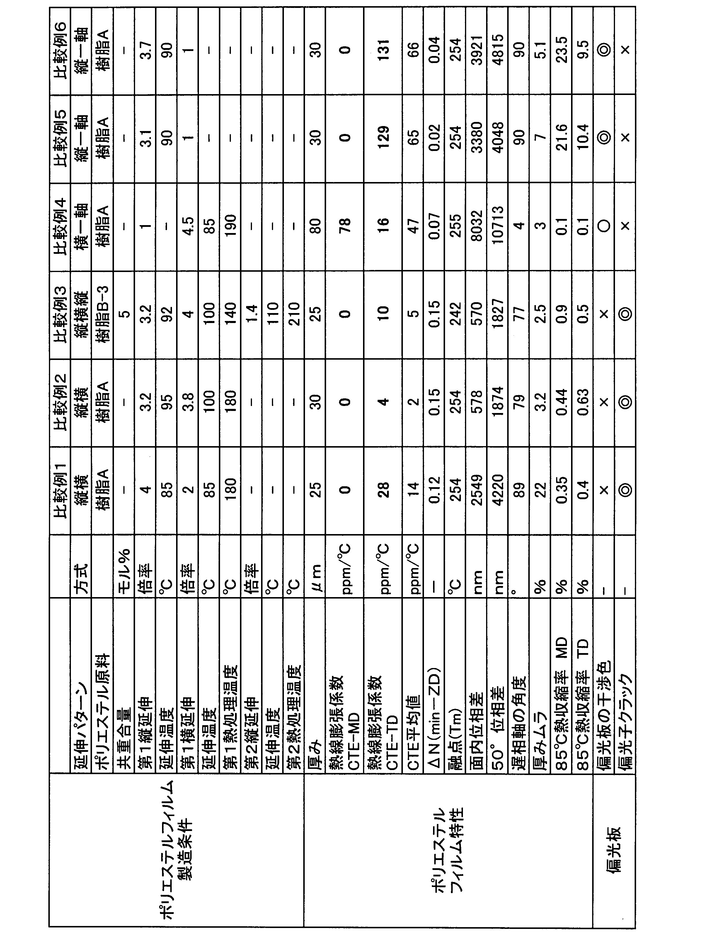
- polyester Film Examples 5 to 10, 15 to 17, Comparative Examples 5 and 6 Various polyester compositions are shown in Tables 1, 2, and 3, and an unstretched film was obtained under the same apparatus configuration, drying of the polyester raw material, and extrusion conditions as in Example 1. Then, various polyester films were obtained by uniaxial stretching under the film-forming conditions of the longitudinal draw ratio, temperature, and heat treatment temperature shown in Tables 1, 2, and 3. It was confirmed that the films obtained in the examples have a low coefficient of linear thermal expansion that is effective in preventing polarizer cracks in the polarizing plate, and have low birefringence that suppresses iridescent unevenness. On the other hand, the comparative example had a large thermal linear expansion coefficient in the film width direction and a large thermal contraction rate at 85° C., and had insufficient performance as a polarizer-protecting polyester film used in a polarizing plate.
- polyester Film Examples 11 to 14, Comparative Example 4 Various polyester compositions are shown in Tables 2 and 3, and an unstretched film was obtained under the same apparatus configuration, drying of the polyester raw material, and extrusion conditions as in Example 1. Next, as shown in Tables 2 and 3, without performing longitudinal stretching, lateral stretching and heat treatment temperature were performed using a tenter to obtain various polyester films uniaxially stretched only in the width (horizontal) direction. It was confirmed that the films obtained in the examples have a low coefficient of linear thermal expansion that is effective in preventing cracks in the polarizing plate, and have low birefringence that suppresses iridescent unevenness. On the other hand, the comparative example had a large coefficient of linear thermal expansion in the film width direction and a large film thickness, and had insufficient performance as a polyester film for protecting a polarizer used in a polarizing plate.
- Example 1 of polarizer A long amorphous isophthalic acid-copolymerized polyethylene terephthalate (IPA-copolymerized PET) film (thickness: 100 ⁇ m) having a water absorption of 0.75% and a Tg of 75° C. was used as a substrate.
- One side of the substrate was subjected to corona treatment, and the corona-treated side was coated with polyvinyl alcohol (degree of polymerization: 4,200, degree of saponification: 99.2 mol%) and acetoacetyl-modified PVA (degree of polymerization: 1,200, degree of acetoacetyl modification: 4.6).
- the resulting laminate was uniaxially stretched 2.0 times at the free end in the machine direction (longitudinal direction) between rolls with different peripheral speeds in an oven at 120°C (in-air auxiliary stretching).
- the laminate was immersed in an insolubilizing bath (an aqueous solution of boric acid obtained by mixing 4 parts by weight of boric acid with 100 parts by weight of water) at a liquid temperature of 30°C for 30 seconds (insolubilizing treatment).
- an insolubilizing bath an aqueous solution of boric acid obtained by mixing 4 parts by weight of boric acid with 100 parts by weight of water
- the laminate is immersed in an aqueous solution of boric acid having a liquid temperature of 70° C. (an aqueous solution obtained by blending 4 parts by weight of boric acid and 5 parts by weight of potassium iodide with respect to 100 parts by weight of water). Meanwhile, the film was uniaxially stretched in the machine direction (longitudinal direction) between rolls with different circumferential speeds so that the total draw ratio was 5.5 (underwater stretching).
- boric acid having a liquid temperature of 70° C.
- the laminate was immersed in a cleaning bath (an aqueous solution obtained by mixing 4 parts by weight of potassium iodide with 100 parts by weight of water) at a liquid temperature of 30°C (washing treatment).
- a cleaning bath an aqueous solution obtained by mixing 4 parts by weight of potassium iodide with 100 parts by weight of water
- Example 1 the polyester film of Example 1 was subjected to corona treatment, and 15.2 wt% of the product name "Superflex 210R” manufactured by Daiichi Kogyo Seiyaku Co., Ltd. and 2.7 wt% of the product name "WS-700” manufactured by Nippon Shokubai Co., Ltd. were added.
- the dissolved aqueous solution was coated so as to have a film thickness of 300 nm after drying, and dried at 80° C. for 1 minute to obtain a polyester film with an easily adhesive layer.
- a PVA-based resin aqueous solution (manufactured by Nippon Synthetic Chemical Industry Co., Ltd., trade name “GOSEFIMER (registered trademark) Z-200”, resin concentration: 3% by weight) that serves as an adhesive layer is applied to the surface of the PVA-based resin layer of the laminate. was applied, and the polyester film with an easy-adhesion layer was laminated. The resulting laminate was heated in an oven maintained at 60°C for 5 minutes. After that, the substrate was peeled off from the PVA-based resin layer to obtain a polarizing plate (polarizer of Example 1 (transmittance: 42.3%, thickness: 5 ⁇ m)/polyester film of Example 1). The polyester film and the polarizer were laminated so that the MD direction of the polyester film and the absorption axis direction of the polarizer were substantially parallel. Table 1 shows the evaluation results of the obtained polarizing plate.
- Examples 2 to 17, Comparative Examples 1 to 6 Various polarizing plates were obtained in the same manner as in Example 1, except that the polyester films obtained in Examples 2 to 17 and Comparative Examples 1 to 6 were used instead of the polyester film of Example 1. Tables 1, 2 and 3 show the evaluation results of the various polarizing plates obtained.
- the polyester films and polarizers of Examples 11 to 14 and Comparative Example 4 are laminated so that the TD direction and the absorption axis direction of the polarizer are substantially parallel because the polyester film is laterally uniaxially stretched. did.
- polyester film and its polarizing plate of the present invention are thin films when applied to image display devices, they eliminate iridescence peculiar to polyester films and have high durability even in environmental changes. It can be provided as a polarizing plate material for panels.
- polyester film 2 easy adhesion layer 3: adhesive layer 4: polarizer 5: slow axis 6: absorption axis 7: polyester film 8: polarizer 9: polarizer protective film 10: liquid crystal cell 11: polarizing reflective film 12: backlight 13: ⁇ / 4 retardation plate 14: organic EL cell 100: polarizing plate 200: polarizing plate 300: polarizing plate 400: circular polarizing plate
Landscapes
- Chemical & Material Sciences (AREA)
- Physics & Mathematics (AREA)
- Medicinal Chemistry (AREA)
- Engineering & Computer Science (AREA)
- Manufacturing & Machinery (AREA)
- Health & Medical Sciences (AREA)
- Chemical Kinetics & Catalysis (AREA)
- Polymers & Plastics (AREA)
- Organic Chemistry (AREA)
- Optics & Photonics (AREA)
- General Physics & Mathematics (AREA)
- Materials Engineering (AREA)
- Polarising Elements (AREA)
- Manufacture Of Macromolecular Shaped Articles (AREA)
Abstract
Description
(1)ジカルボン酸成分がテレフタル酸75モル%以上であり、ジオール成分がエチレングリコール75モル%以上からなるポリエステルフィルムであって、30℃から70℃の温度範囲でのフィルムの面内方向の熱線膨張係数が70ppm/℃以下であり、面内方向の最も小さい屈折率と厚み方向の屈折率の差が0.09以下であり、厚みが40μm以下である偏光子保護用ポリエステルフィルム。
(2)面内位相差が400nm~3000nmである、(1)に記載の偏光子保護用ポリエステルフィルム。
(3)フィルムの幅方向の厚みムラが10%以下である、(1)または(2)に記載の偏光子保護用ポリエステルフィルム。
(4)フィルムの固有粘度が0.80dl/g以上、融点が245℃~210℃である、(1)から(3)のいずれかに記載の偏光子保護用ポリエステルフィルム。
(5)共重合成分が、3モル%以上25モル%以下であり、少なくともアジピン酸、イソフタル酸、シクロヘキサンジメタノールから選ばれた成分を含む、(1)から(4)のいずれかに記載の偏光子保護用ポリエステルフィルム。
(6)偏光子の吸収軸とポリエステルフィルムの遅相軸のなす角度が5°以下である、(1)から(5)のいずれかに記載の偏光子保護用ポリエステルフィルム。
(7)A層/B層/A層の3層積層であって、A層の厚みが1μm以下である、(1)から(6)のいずれかに記載の偏光子保護用ポリエステルフィルム。
(8)偏光子と、偏光子の一方の側に配置された(1)から(7)のいずれかに記載のポリエステルフィルムを備える偏光板。
(9)前記偏光子の厚みが20μm以下である、(8)に記載の偏光板。
(10)前記ポリエステルフィルムの前記偏光子側に配置された易接着層をさらに含む、(8)または(9)に記載の偏光板。
(11)前記易接着層が微粒子を含む、(10)に記載の偏光板。
(12)前記易接着層の厚みが0.35μm以下である、(10)または(11)に記載の偏光板。
(13)前記易接着層の屈折率が1.6以下である、(10)から(12)のいずれかに記載の偏光板。
本発明におけるポリエステルは、主たるジカルボン酸成分としてのテレフタル酸と主たるジオール成分としてエチレングリコールが重合反応により得られるポリエチレンテレフタレートを主骨格とする構成である。
本発明の偏光板は、偏光子と、偏光子の一方の側に配置された前述した偏光子保護用ポリエステルフィルムを備える偏光板である。偏光子としては、任意の適切な偏光子が採用され得る。例えば、偏光子を形成する樹脂フィルムは、単層の樹脂フィルムであってもよく、二層以上の積層体であってもよい。単層の樹脂フィルムから構成される偏光子の具体例としては、ポリビニルアルコール(PVA)系フィルム、部分ホルマール化PVA系フィルム、エチレン・酢酸ビニル共重合体系部分ケン化フィルム等の親水性高分子フィルムに、ヨウ素や二色性染料等の二色性物質による染色処理および延伸処理が施されたもの、PVAの脱水処理物やポリ塩化ビニルの脱塩酸処理物等ポリエン系配向フィルム等が挙げられる。好ましくは、光学特性に優れることから、PVA系フィルムをヨウ素で染色し一軸延伸して得られた偏光子が用いられる。
1つの実施形態においては、上記易接着層の屈折率は、好ましくは1.45~1.60である。このような範囲であれば、画像表示装置に適用した際に他部材の光学特性を阻害し難い易接着層付ポリエステルフィルムを得ることができる。1つの実施形態においては、上記ポリエステルフィルムは、その少なくとも一方の側に、アンチブロック層を備え得る。アンチブロック層の構成は、上記で説明した易接着層の構成が採用され得る。好ましくは、アンチブロック層は、上記微粒子を含む。
上記ポリエステルフィルムは、上記ポリエステル系樹脂を含むフィルム形成材料(樹脂組成物)をフィルム状に成形する成形工程、および、該成形されたフィルムを延伸する延伸工程を経て得られる。好ましくは、延伸工程は、フィルム延伸の前に行われるフィルムの予熱処理、およびフィルム延伸の後に行われる熱処理を含む。1つの実施形態においては、ポリエステルフィルムは、長尺状(または長尺体から切り出した形状)で提供される。長尺状とは、ロール状ともいう。
図1(a)は、本発明の1つの実施形態による偏光板の概略断面図である。偏光板100は、偏光子4と、偏光子4の一方の側に配置されたポリエステルフィルム1とを備える。ポリエステルフィルム1としては、上記で説明した本発明のポリエステルフィルムが用いられる。偏光子の他方の側には任意の適切な別の偏光子保護フィルムが配置されてもよく、偏光子保護フィルムは配置されなくてもよい。1つの実施形態においては、偏光子4とポリエステルフィルム1(または別の偏光子保護フィルム)は、接着剤層3を介して積層される。また、接着剤層3とポリエステルフィルム1とを接着させるために、ポリエステルフィルム1上に易接着層2が積層される。
本発明における特性の測定方法、および効果の評価方法は次のとおりである。
(1)ポリエステルの組成
本発明の共重合ポリエチレンテレフタレートの組成は、重合時に共重合成分のモノマー量をジオール成分とジカルボン酸成分の配合量で調整しているが、1H-NMR及びTMAH添加型同時誘導体化熱分解GC/MS 測定により、共重合モノマー同定と組成比の算出を行うことができる。ポリエステルフィルムやそのチップを約30mg 程度採取し、重水素化クロロホルム(CDCl3)と重水素化ヘキサフルオロイソプロパノール(HFIP-d2)の混液に溶解した後、40℃での温度で1H-NMR 測定した。なお、混液の比率はCDCl3:HFIP-d2=2:1 とした。同定に際しては、既知のテレフタル酸、アジピン酸、イソフタル酸、シクロヘキサンジメタノール、エチレングリコールの各種モノマーの単独スペクトルの既存データに基づき同定し、その組成は、そのスペクトルのピーク面積比から共重合比率を算出した。
ポリエステル樹脂およびフィルムの固有粘度は、ポリエステル樹脂またはフィルム0.1gをオルトクロロフェノール10mlに160℃、20分で溶解し、オストワルド粘度計を用いて25℃にて溶液粘度を測定した。
先端が平坦で直径4mmのダイヤルゲージ厚さ計((株)ミツトヨ製No2109-10)を用いてフィルムの厚さを測定した。フィルムを置く台は、メーカー付属の専用台(Code 7002)を用いた。なお、測定は場所を変えて5回実施し、その平均値でもってフィルムの厚さ(μm)とした。
ロータリーミクロトームRMS型(日本ミクロトーム研究所製)を用いてフィルムの断面を切り出した。厚み方向と長手方向の断面、及びフィルム厚み方向と幅方向の断面とを切り出した。該断面をイオンコーター(エイコー社1B-3型)で白金-パラジウムを蒸着した後、日本電子製電界放射走査電子顕微鏡(FE-SEM)JSM-6700Fで100~5000倍の断面写真を撮影した。フィルム厚みの全体は、ダイヤルゲージ厚さ計を基準として、粒子含有の表層厚み等の構成厚みを求めた。
前記で構成厚みが観察できない場合は、フィルムをエポキシ樹脂に包埋し、フィルム断面をミクロトームで切り出した。該断面を透過型電子顕微鏡(日本電子製JEM-1400 Plus)でフィルム断面全体像を把握できる程度の倍率(100~5000倍で任意)で観察し、積層構成である表層の厚みを求めた。
熱機械測定装置TMA/SS6000(セイコーインスツルメンツ社製)を用い、試料幅4mmとして、試料長さ(チャック間距離)20mmのサンプルに対し、定荷重モードで測定時の張力:19.6mNとする。15℃から220℃まで昇温速度10℃/分で昇温させ、各温度(℃)における試料の寸法の値を得る。そして、30℃における試料の寸法L(30℃)(mm)と70℃における寸法L(70℃)(mm)から、下記式(1)から算出する。なお、測定長が長手方向の熱線膨張係数の値をCTE-MD、幅方向の熱線膨張係数の値をCTE-TDとした。
熱線膨張係数(ppm/℃)=X/チャック間距離/(70-30)×106・・・式(1)
X(mm):フィルム温度30℃~70℃に対応するフィルム変位量
=L(70℃)(mm)-L(30℃)(mm)
得られたポリエステルフィルムの幅方向中央部から長手方向(MD)4cm×幅方向(TD)3.5cmでサンプルを切り出し、ナトリウムD線(波長589nm(約590nm))を光源とし、マウント液としてヨウ化メチレンを用いることにより、25℃にてアッベ屈折計4T(アタゴ(株)製)を用いて、フィルムの長手方向の屈折率N(MD)、幅方向の屈折率N(TD)、厚み方向の屈折率N(ZD)を、JIS K7142(2014)A法に準拠して測定した。テストピースの屈折率は、1.74のものを用いた。
ΔN(min-ZD)
=面内方向の最も小さい屈折率N(min)-厚み方向の屈折率N(ZD)・・・式(2)
前記方法で特定できないときは、次項の位相差測定装置の進相軸の方位を採用した。
王子計測機器(株)製 位相差測定装置(KOBRA-21ADH)を用いた。サンプルをフィルム幅方向中央部から幅方向4cm×長手方向3cmで切り出し、フィルム幅方向が本測定装置にて定義されている角度0°となるように装置に設置し、波長590nmにおける入射角0°における面内位相差、および入射角度50°における位相差、ポリエステルフィルムの遅相軸となる配向角を測定した。
SIIナノテクノロジー(旧セイコー電子工業、現日立ハイテクサイエンス)製示差走査熱量測定装置ロボットDSC-RDC6220を、データ解析にはMuse標準解析“Standard Analysis Ver.9”を用いて、JIS K7121 (1999年)、JIS K-7122(1987年版)に準拠して、融点Tmを測定した。本発明のポリエステルフィルム5mgをサンプルに用い、25℃から20℃/分で300℃まで昇温した際のDSC曲線より得られた吸熱ピークの頂点の温度を融点Tmとした。吸熱ピークが複数存在する場合は、最も高温側の吸熱ピークの頂点の温度を融点Tmとした。
ポリエステルフィルムの全幅中央部から、厚みムラ評価のため、フィルム幅方向と平行かつ測定長が20cm以上となるように幅5cmのサンプルを切り出した。次いで、そのサンプルを用いて、アンリツ社製 フィルムシックネステスターKG601Aを用いて、走行速度0.15m/分でフィルムを走行させる。アンリツ社製 広範囲電子マイクロメータK306Cで厚み変化を検出し、キーエンス社製 高精度温度電圧計測ユニットNT-TH08で時間に対する厚み変化を保存した。このときのサンプリング周期:100ms、AD積分時間:2msである。キーエンス社製解析ソフトwave loggerにて厚みデータを読み出し、次式(3)にて厚みムラを算出した。測定長は、20cmとした。
厚みムラ(%)=(最大厚さ-最小厚さ)/平均厚さ×100・・・式(3)
フィルム幅方向の中央部から長手方向及び幅方向にサンプルサイズ:幅10mm×測定方向200mmにサンプルを切り出した。次いで、測定方向の初期長100mmとする間隔で標線をサンプルに記載し、Nikon社製万能投影機(Model V-16A、20×DPレンズ)を利用して、標線間の距離To(mm)を小数点以下3桁まで正確に測定した。次いで3g荷重下で85℃に加熱した熱風オーブン(エスペック社製GPHH-202)内に6時間設置し加熱処理を行う。熱処理後の標線間の距離T(mm)を測定し、加熱前後の標線間の距離の変化から下記式(4)により熱収縮率を算出する。
熱収縮率(%)=((To-T)/To)×100・・・式(4)
LGD社製の液晶TV「45UH7500」から液晶セルを取り出し、バックライト側の偏光板をはがした。当該液晶TVの偏光板をはがした面に、実施例および比較例で得られた偏光板を、粘着剤を介して、偏光子の吸収軸が液晶TVの短辺側になるように貼り合せた。実施例および比較例で得られた偏光板が張り合わされた液晶セルを再度設置し、TVを白表示で点灯させた。点灯させた液晶TVの、極角60°の角度で、全方位目視確認し、虹ムラの有無を観察した。以下の基準で評価した。
◎:虹ムラは全く認められなかった
○:虹ムラは認められなかった
△:虹ムラがわずかに認められた
×:虹ムラが顕著に認められた
実施例および比較例で得られた偏光板について、冷熱衝撃試験機(ESPEC製)を用いて、評価を行った。実施例及び比較例で得られた偏光板を、横50mm×縦150mmに裁断した。その際、偏光子の吸収軸方向が裁断後の偏光板の横方向(短辺)と平行となるサンプルと、偏光子の透過軸方向が裁断後の偏光板の横方向(短辺)と平行となるサンプルとを作製した。偏光板の保護フィルム(ポリエステルフィルム)が積層されていない面と、0.5mm厚の無アルカリガラスとを、アクリル系粘着剤を介して貼り合せ、サンプルを作製した。得られたサンプルを冷熱衝撃試験機のテストエリアに入れ、室温から30分かけてテストエリア内を-40℃まで降温した。次いで、30分かけてテストエリア内を85℃まで昇温した後、30分かけて-40℃まで再度降温した。この-40℃から85℃に昇温し、再度-40℃まで降温する工程を1サイクルとして、100サイクル、200サイクル繰り返した後、積層体を取り出し、目視にてクラック発生の有無を確認し、以下の基準で評価した。
◎:250サイクル繰り返した後でも、クラックは認められなかった。
○:200サイクル繰り返した後では、クラックは認められなかったが
250サイクル繰り返した後に、クラックが発生していた。
△:100サイクル繰り返した後では、クラックは認められなかったが、
200サイクル繰り返した後に、クラックが発生していた。
×:100サイクル繰り返した後に、クラックが発生していた。
樹脂Aとして、以下のものを準備した。
(樹脂A)テレフタル酸ジメチル100重量部、エチレングリコール60重量部の混合物に、テレフタル酸ジメチル量に対して酢酸マグネシウム0.09重量部、三酸化アンチモン0.03重量部を添加して、常法により加熱昇温してエステル交換反応を行う。次いで、該エステル交換反応生成物に、テレフタル酸ジメチル量に対して、リン酸85%水溶液0.020重量部を添加した後、重縮合反応層に移行する。さらに、加熱昇温しながら反応系を徐々に減圧して1mmHgの減圧下、290℃で常法により重縮合反応を行い、IV=0.64dl/gのポリエチレンテレフタレートを得た。ガラス転移点78℃
IV=0.85dl/g イソフタル酸(IPA 5モル%)を共重合したポリエチレンテレフタレート。ガラス転移点78℃
IV=0.72dl/g イソフタル酸(IPA 10モル%)を共重合したポリエチレンテレフタレート。ガラス転移点78℃
IV=0.80dl/g イソフタル酸(IPA 5モル%)を共重合したポリエチレンテレフタレート。ガラス転移点78℃
IV=0.89dl/g イソフタル酸(IPA 10モル%)を共重合したポリエチレンテレフタレート。ガラス転移点78℃
(樹脂C)IV=0.75dl/g シクロヘキサンジメタノール(CHDM 10モル%)を共重合したポリエチレンテレフタレート。ガラス転移点80℃。
(樹脂D)IV=0.72dl/g アジピン酸(10モル%)を共重合したポリエチレンテレフタレート。ガラス転移点63℃。
2軸混練機を用いて、外部添加剤として平均粒径1.2μmの凝集シリカ粒子を2重量%含有させた樹脂B-1のペレットをマスターペレット1とした。次に、粒子添加を行わなかった樹脂B-1のペレットをマスターペレット2とした。
各種のポリエステル組成は表1、表3の通りであり、実施例1と同様の装置構成、ポリエステル原料の乾燥、押出条件で未延伸フィルムを得た。次いで、表1、表3に示した第一縦横延伸、熱処理、および第二の縦延伸、熱固定の製膜条件にて、逐次二軸延伸された各種ポリエステルフィルムを得た。実施例にて得られたフィルムについては、偏光板の偏光子クラック防止に有効な低熱線膨張係数を実現し、また虹ムラを抑制する低複屈折性であった。特に実施例3は、厚みムラや熱寸法安定性に優れており、偏光子保護として最適であることを確認した。一方、比較例については、フィルム長手方向、幅方向とも熱線膨張係数は非常に優れている反面、虹ムラを発生させるほど複屈折が大きく、偏光板に用いる偏光子保護用ポリエステルフィルムとしては不十分な性能であった。
各種のポリエステル組成は表1、表2、表3の通りであり、実施例1と同様の装置構成、ポリエステル原料の乾燥、押出条件で未延伸フィルムを得た。次いで、表1、表2、表3に示した縦延伸倍率、温度、熱処理温度の製膜条件にて、一軸延伸された各種ポリエステルフィルムを得た。実施例にて得られたフィルムについては、偏光板の偏光子クラック防止に有効な低熱線膨張係数を実現し、また虹ムラを抑制する低複屈折性であることを確認した。一方、比較例については、フィルム幅方向の熱線膨張係数が大きく、また85℃における熱収縮率も大きく、偏光板に用いる偏光子保護用ポリエステルフィルムとしては不十分な性能であった。
各種のポリエステル組成は表2、表3の通りであり、実施例1と同様の装置構成、ポリエステル原料の乾燥、押出条件で未延伸フィルムを得た。次いで、表2、表3に示したとおり、縦延伸は行わず、テンターにて横延伸、及び熱処理温度を実施し、幅(横)方向にのみ一軸延伸された各種ポリエステルフィルムを得た。実施例にて得られたフィルムについては、偏光板のクラック防止に有効な低熱線膨張係数を実現し、また虹ムラを抑制する低複屈折性であることを確認した。一方、比較例については、フィルム幅方向の熱線膨張係数が大きく、またフィルム厚みも厚く、偏光板に用いる偏光子保護用ポリエステルフィルムとしては不十分な性能であった。
基材として、長尺状で、吸水率0.75%、Tg75℃の非晶質のイソフタル酸共重合ポリエチレンテレフタレート(IPA共重合PET)フィルム(厚み:100μm)を用いた。基材の片面に、コロナ処理を施し、このコロナ処理面に、ポリビニルアルコール(重合度4200、ケン化度99.2モル%)およびアセトアセチル変性PVA(重合度1200、アセトアセチル変性度4.6%、ケン化度99.0モル%以上、日本合成化学工業社製、商品名「ゴーセファイマー(登録商標)Z200」)を9:1の比で含む水溶液を25℃で塗布および乾燥して、厚み11μmのPVA系樹脂層を形成し、積層体を作製した。
得られた偏光板の評価結果を表1に示す。
実施例1のポリエステルフィルムに代えて、実施例2~17、比較例1~6で得られたポリエステルフィルムを用いたこと以外は、実施例1と同様にして各種の偏光板を得た。
得られた各種の偏光板の評価結果を表1、表2、表3に示す。なお、実施例11~14、比較例4のポリエステルフィルムと偏光子とは、ポリエステルフィルムは横一軸延伸であるため、そのTD方向と偏光子の吸収軸方向とが略平行となるようにして積層した。


2:易接着層
3:接着剤層
4:偏光子
5:遅相軸
6:吸収軸
7:ポリエステルフィルム
8:偏光子
9:偏光子保護フィルム
10:液晶セル
11:偏光反射フィルム
12:バックライト
13:λ/4位相差板
14:有機ELセル
100:偏光板
200:偏光板
300:偏光板
400:円偏光板
Claims (13)
- ジカルボン酸成分がテレフタル酸75モル%以上であり、ジオール成分がエチレングリコール75モル%以上からなるポリエステルフィルムであって、30℃から70℃の温度範囲でのフィルムの面内方向の熱線膨張係数が70ppm/℃以下であり、面内方向の最も小さい屈折率と厚み方向の屈折率の差が0.09以下であり、厚みが40μm以下である偏光子保護用ポリエステルフィルム。
- 面内位相差が400nm~3000nmである、請求項1に記載の偏光子保護用ポリエステルフィルム。
- フィルムの幅方向の厚みムラが10%以下である、請求項1または2に記載の偏光子保護用ポリエステルフィルム。
- フィルムの固有粘度が0.80dl/g以上、融点が245℃~210℃である、請求項1から3のいずれかに記載の偏光子保護用ポリエステルフィルム。
- 共重合成分が、3モル%以上25モル%以下であり、少なくともアジピン酸、イソフタル酸、シクロヘキサンジメタノールから選ばれた成分を含む、請求項1から4のいずれかに記載の偏光子保護用ポリエステルフィルム。
- 偏光子の吸収軸とポリエステルフィルムの遅相軸のなす角度が5°以下である、請求項1から5のいずれかに記載の偏光子保護用ポリエステルフィルム。
- A層/B層/A層の3層積層であって、A層の厚みが1μm以下である、請求項1から6のいずれかに記載の偏光子保護用ポリエステルフィルム。
- 偏光子と、偏光子の一方の側に配置された請求項1から7のいずれかに記載のポリエステルフィルムを備える偏光板。
- 前記偏光子の厚みが20μm以下である、請求項8に記載の偏光板。
- 前記ポリエステルフィルムの前記偏光子側に配置された易接着層をさらに含む、請求項8または9に記載の偏光板。
- 前記易接着層が微粒子を含む、請求項10に記載の偏光板。
- 前記易接着層の厚みが0.35μm以下である、請求項10または11に記載の偏光板。
- 前記易接着層の屈折率が1.6以下である、請求項10から12のいずれかに記載の偏光板。
Priority Applications (3)
| Application Number | Priority Date | Filing Date | Title |
|---|---|---|---|
| KR1020237021624A KR20230163350A9 (ko) | 2021-03-31 | 2022-03-24 | 편광자 보호용 폴리에스테르 필름, 및 그것을 사용한 편광판 |
| JP2022521034A JPWO2022210249A1 (ja) | 2021-03-31 | 2022-03-24 | |
| CN202280018633.8A CN116964497A (zh) | 2021-03-31 | 2022-03-24 | 偏光片保护用聚酯膜、以及使用其的偏光板 |
Applications Claiming Priority (2)
| Application Number | Priority Date | Filing Date | Title |
|---|---|---|---|
| JP2021-059129 | 2021-03-31 | ||
| JP2021059129 | 2021-03-31 |
Publications (1)
| Publication Number | Publication Date |
|---|---|
| WO2022210249A1 true WO2022210249A1 (ja) | 2022-10-06 |
Family
ID=83458748
Family Applications (1)
| Application Number | Title | Priority Date | Filing Date |
|---|---|---|---|
| PCT/JP2022/013909 Ceased WO2022210249A1 (ja) | 2021-03-31 | 2022-03-24 | 偏光子保護用ポリエステルフィルム、およびそれを用いた偏光板 |
Country Status (4)
| Country | Link |
|---|---|
| JP (1) | JPWO2022210249A1 (ja) |
| KR (1) | KR20230163350A9 (ja) |
| CN (1) | CN116964497A (ja) |
| WO (1) | WO2022210249A1 (ja) |
Citations (6)
| Publication number | Priority date | Publication date | Assignee | Title |
|---|---|---|---|---|
| JPS5191972A (ja) * | 1975-02-12 | 1976-08-12 | Horiechirenterefutareetofuirumu | |
| JP2004226799A (ja) * | 2003-01-24 | 2004-08-12 | Konica Minolta Holdings Inc | 偏光板保護フィルム、偏光板及び画像表示用材料 |
| JP2016001304A (ja) * | 2014-05-23 | 2016-01-07 | 東レ株式会社 | 光学用ポリエステルフィルム及びそれを用いた偏光板、透明導電性フィルム |
| JP2016001305A (ja) * | 2014-05-23 | 2016-01-07 | 東レ株式会社 | 光学用ポリエステルフィルム及びそれを用いた偏光板、透明導電性フィルム |
| WO2020050612A1 (ko) * | 2018-09-04 | 2020-03-12 | 주식회사 엘지화학 | 투과도 가변 디바이스 |
| JP2020126217A (ja) * | 2019-01-31 | 2020-08-20 | 日東電工株式会社 | ポリエステルフィルム、および該ポリエステルフィルムを含む偏光板 |
Family Cites Families (3)
| Publication number | Priority date | Publication date | Assignee | Title |
|---|---|---|---|---|
| CN110187549B (zh) | 2010-06-22 | 2022-07-15 | 东洋纺株式会社 | 液晶显示装置、偏振板及偏振片保护膜 |
| JP6197360B2 (ja) | 2013-05-16 | 2017-09-20 | 東洋紡株式会社 | 画像表示装置 |
| WO2020158113A1 (ja) | 2019-01-31 | 2020-08-06 | 日東電工株式会社 | ポリエステルフィルム、および該ポリエステルフィルムを含む偏光板 |
-
2022
- 2022-03-24 WO PCT/JP2022/013909 patent/WO2022210249A1/ja not_active Ceased
- 2022-03-24 CN CN202280018633.8A patent/CN116964497A/zh active Pending
- 2022-03-24 JP JP2022521034A patent/JPWO2022210249A1/ja active Pending
- 2022-03-24 KR KR1020237021624A patent/KR20230163350A9/ko active Pending
Patent Citations (6)
| Publication number | Priority date | Publication date | Assignee | Title |
|---|---|---|---|---|
| JPS5191972A (ja) * | 1975-02-12 | 1976-08-12 | Horiechirenterefutareetofuirumu | |
| JP2004226799A (ja) * | 2003-01-24 | 2004-08-12 | Konica Minolta Holdings Inc | 偏光板保護フィルム、偏光板及び画像表示用材料 |
| JP2016001304A (ja) * | 2014-05-23 | 2016-01-07 | 東レ株式会社 | 光学用ポリエステルフィルム及びそれを用いた偏光板、透明導電性フィルム |
| JP2016001305A (ja) * | 2014-05-23 | 2016-01-07 | 東レ株式会社 | 光学用ポリエステルフィルム及びそれを用いた偏光板、透明導電性フィルム |
| WO2020050612A1 (ko) * | 2018-09-04 | 2020-03-12 | 주식회사 엘지화학 | 투과도 가변 디바이스 |
| JP2020126217A (ja) * | 2019-01-31 | 2020-08-20 | 日東電工株式会社 | ポリエステルフィルム、および該ポリエステルフィルムを含む偏光板 |
Also Published As
| Publication number | Publication date |
|---|---|
| JPWO2022210249A1 (ja) | 2022-10-06 |
| TW202305032A (zh) | 2023-02-01 |
| KR20230163350A9 (ko) | 2024-11-13 |
| KR20230163350A (ko) | 2023-11-30 |
| CN116964497A (zh) | 2023-10-27 |
Similar Documents
| Publication | Publication Date | Title |
|---|---|---|
| JP2023159194A (ja) | ポリエステルフィルム、および該ポリエステルフィルムを含む偏光板 | |
| JP2026015504A (ja) | ポリエステルフィルム、および該ポリエステルフィルムを含む偏光板 | |
| WO2022210249A1 (ja) | 偏光子保護用ポリエステルフィルム、およびそれを用いた偏光板 | |
| JP2022179612A (ja) | ポリエステルフィルム、および該ポリエステルフィルムを含む偏光板 | |
| JP7154188B2 (ja) | ポリエステルフィルム、および該ポリエステルフィルムを含む偏光板 | |
| CN116057437A (zh) | 偏振片保护用聚酯薄膜、和包含该聚酯薄膜的偏光板 | |
| CN116057435A (zh) | 偏振片保护用聚酯薄膜、和包含该聚酯薄膜的偏光板 | |
| CN116057436A (zh) | 偏振片保护用聚酯薄膜、和包含该聚酯薄膜的偏光板 | |
| JP2022154032A (ja) | ポリエステルフィルム |
Legal Events
| Date | Code | Title | Description |
|---|---|---|---|
| ENP | Entry into the national phase |
Ref document number: 2022521034 Country of ref document: JP Kind code of ref document: A |
|
| 121 | Ep: the epo has been informed by wipo that ep was designated in this application |
Ref document number: 22780463 Country of ref document: EP Kind code of ref document: A1 |
|
| WWE | Wipo information: entry into national phase |
Ref document number: 202280018633.8 Country of ref document: CN |
|
| NENP | Non-entry into the national phase |
Ref country code: DE |
|
| 122 | Ep: pct application non-entry in european phase |
Ref document number: 22780463 Country of ref document: EP Kind code of ref document: A1 |