以下、本発明の実施形態について図面を参照して説明する。なお、以下の説明における前後左右等の向きは、特に記載が無ければ以下に説明する車両における向きと同一とする。また以下の説明に用いる図中適所には、車両前方を示す矢印FR、車両左方を示す矢印LH、車両上方を示す矢印UP、が示されている。
Hereinafter, embodiments of the present invention will be described with reference to the drawings. Note that directions such as front, rear, left, and right in the following description are the same as directions in the vehicle described below unless otherwise specified. An arrow FR indicating the front of the vehicle, an arrow LH indicating the left of the vehicle, and an arrow UP indicating the upper side of the vehicle are shown at appropriate locations in the drawings used in the following description.
<車両全体>
図1に示すように、本実施形態は、鞍乗り型車両の一例としての自動二輪車1に適用されている。自動二輪車1の前輪2は、左右一対のフロントフォーク3の下端部に支持されている。左右フロントフォーク3の上部は、ステアリングステム4を介して、車体フレーム5の前端部のヘッドパイプ6に支持されている。ステアリングステム4のトップブリッジ上には、バータイプの操向ハンドル4aが取り付けられている。
<Whole vehicle>
As shown in FIG. 1, the present embodiment is applied to a motorcycle 1 as an example of a saddle type vehicle. A front wheel 2 of the motorcycle 1 is supported by lower ends of a pair of left and right front forks 3 . Upper portions of the left and right front forks 3 are supported by a head pipe 6 at the front end of the body frame 5 via a steering stem 4 . A bar-type steering handle 4a is attached to the top bridge of the steering stem 4. As shown in FIG.
車体フレーム5は、ヘッドパイプ6と、ヘッドパイプ6から車幅方向(左右方向)中央を下後方へ延びるメインフレーム7と、メインフレーム7の後端部の下方に設けられるピボットフレーム8と、メインフレーム7およびピボットフレーム8の後方に連なるシートフレーム9と、を備えている。ピボットフレーム8には、スイングアーム11の前端部が揺動可能に枢支されている。スイングアーム11の後端部には、自動二輪車1の後輪12が支持されている。
The vehicle body frame 5 includes a head pipe 6, a main frame 7 extending downward and rearward from the head pipe 6 at the center in the vehicle width direction (left-right direction), a pivot frame 8 provided below the rear end of the main frame 7, and a main frame. A seat frame 9 connected to the rear of the frame 7 and the pivot frame 8 is provided. A front end portion of a swing arm 11 is pivotally supported on the pivot frame 8 so as to be able to swing. A rear wheel 12 of the motorcycle 1 is supported at the rear end of the swing arm 11 .
左右メインフレーム7の上方には、燃料タンク18が支持されている。燃料タンク18の後方でシートフレーム9の上方には、前シート19および後シート19aが支持されている。燃料タンク18の後部の左右両側には、車幅方向内側に凹んだニーグリップ部18aが形成されている。左右ニーグリップ部18aは、以下の部位に整合するように形成されている。その部位とは、前シート19に着座した運転者の左右の膝周辺の内側である。前シート19の下方の左右両側には、ステップ18bが支持されている。ステップ18bには、運転者が足首から先の足部を載せる。
A fuel tank 18 is supported above the left and right main frames 7 . A front seat 19 and a rear seat 19 a are supported behind the fuel tank 18 and above the seat frame 9 . On both left and right sides of the rear portion of the fuel tank 18, knee grip portions 18a recessed inward in the vehicle width direction are formed. The left and right knee grip portions 18a are formed so as to match the following portions. The part is the inside of the left and right knees of the driver seated on the front seat 19 . Steps 18 b are supported on both left and right sides below the front seat 19 . On step 18b, the driver puts his/her foot from the ankle on.
メインフレーム7の下方には、自動二輪車1の原動機を含むパワーユニットPUが懸架されている。パワーユニットPUは、その前側に位置するエンジン(内燃機関、原動機)13と、後側に位置する変速機21と、を一体に有している。エンジン13は、例えばクランクシャフト14の回転軸を左右方向(車幅方向)に沿わせた複数気筒エンジンである。
A power unit PU including the prime mover of the motorcycle 1 is suspended below the main frame 7 . The power unit PU integrally has an engine (internal combustion engine, prime mover) 13 located on the front side thereof and a transmission 21 located on the rear side thereof. The engine 13 is, for example, a multi-cylinder engine in which the rotation axis of the crankshaft 14 extends in the left-right direction (vehicle width direction).
エンジン13は、クランクケース15の前部上方にシリンダ16を起立させている。クランクケース15の後部は、変速機21を収容する変速機ケース17とされている。クランクケース15の右側部には、変速機ケース17の右側部に渡る右カバー17aが取り付けられている。右カバー17aは、クラッチ装置26を覆うクラッチカバーでもある。パワーユニットPUは、後輪12と、例えばチェーン式伝動機構(不図示)を介して連係されている。
The engine 13 has a cylinder 16 erected above the front portion of the crankcase 15 . A rear part of the crankcase 15 is a transmission case 17 that accommodates the transmission 21 . A right cover 17 a that extends over the right side of the transmission case 17 is attached to the right side of the crankcase 15 . The right cover 17 a also serves as a clutch cover that covers the clutch device 26 . Power unit PU is linked to rear wheel 12 via, for example, a chain transmission mechanism (not shown).
<変速機>
図2を併せて参照し、変速機21は、有段式のトランスミッションである。変速機21は、メインシャフト22およびカウンタシャフト23ならびに両シャフト22,23に跨る変速ギヤ群24を有する。カウンタシャフト23は、変速機21ひいてはパワーユニットPUの出力軸を構成している。カウンタシャフト23の左端部は、変速機ケース17の後部左側に突出し、前記チェーン式伝動機構を介して後輪12に連結されている。
<Transmission>
Also referring to FIG. 2, the transmission 21 is a stepped transmission. The transmission 21 has a main shaft 22 , a counter shaft 23 , and a transmission gear group 24 straddling both shafts 22 , 23 . Countershaft 23 constitutes an output shaft of transmission 21 and thus power unit PU. A left end portion of the countershaft 23 projects to the rear left side of the transmission case 17 and is connected to the rear wheel 12 via the chain type transmission mechanism.
変速機21のメインシャフト22及びカウンタシャフト23は、クランクシャフト14の後方に配置されている。メインシャフト22の右端部には、クラッチ装置26が同軸配置されている。クラッチ装置26は、エンジン13のクランクシャフト14と、変速機21のメインシャフト22と、の間の動力伝達を断接させる。クラッチ装置26は、乗員によるクラッチ操作子(例えば不図示のクラッチレバー)の操作、および後に詳述するクラッチアクチュエータ50の作動、の少なくとも一方により断接作動する。
The main shaft 22 and countershaft 23 of the transmission 21 are arranged behind the crankshaft 14 . A clutch device 26 is coaxially arranged at the right end of the main shaft 22 . The clutch device 26 connects and disconnects power transmission between the crankshaft 14 of the engine 13 and the main shaft 22 of the transmission 21 . The clutch device 26 is engaged and disengaged by at least one of the operation of a clutch operator (for example, a clutch lever not shown) by the passenger and the operation of a clutch actuator 50 which will be described in detail later.
クラッチ装置26は、例えば湿式多板クラッチであり、いわゆるノーマルクローズクラッチである。クランクシャフト14の回転動力は、クラッチ装置26を介してメインシャフト22に伝達され、メインシャフト22から変速ギヤ群24の任意のギヤ対を介してカウンタシャフト23に伝達される。カウンタシャフト23におけるクランクケース15の後部左側に突出した左端部には、前記チェーン式伝動機構のドライブスプロケット27が取り付けられている。
The clutch device 26 is, for example, a wet multi-plate clutch, a so-called normally closed clutch. Rotational power of the crankshaft 14 is transmitted to the main shaft 22 via the clutch device 26 and transmitted from the main shaft 22 to the countershaft 23 via an arbitrary gear pair of the transmission gear group 24 . A drive sprocket 27 of the chain transmission mechanism is attached to the left end portion of the countershaft 23 that protrudes to the rear left side of the crankcase 15 .
変速機ケース17内で変速機21の近傍には、変速ギヤ群24のギヤ対を切り替えるチェンジ機構25が収容されている。チェンジ機構25は、両シャフト22,23と平行な中空円筒状のシフトドラム32を有する。このシフトドラム32の回転により、チェンジ機構25は、複数のシフトフォーク32aを作動させる。この作動は、シフトドラム32の外周に形成されたリード溝のパターンに応じてなされる。この作動により、チェンジ機構25は、変速ギヤ群24における両シャフト22,23間の動力伝達に用いるギヤ対を切り替える。
In the vicinity of the transmission 21 in the transmission case 17, a change mechanism 25 for switching the gear pair of the transmission gear group 24 is accommodated. The change mechanism 25 has a hollow cylindrical shift drum 32 parallel to the shafts 22 and 23 . By rotating the shift drum 32, the change mechanism 25 operates the plurality of shift forks 32a. This operation is performed according to the pattern of lead grooves formed on the outer circumference of the shift drum 32 . By this operation, the change mechanism 25 switches the gear pair used for power transmission between the shafts 22 and 23 in the transmission gear group 24 .
ここで、自動二輪車1は、変速機21の変速操作(シフトペダル(不図示)の足操作)のみを運転者が行い、クラッチ装置26の断接操作は前記シフトペダルの操作に応じて電気制御により自動で行う。すなわち、自動二輪車1は、いわゆるセミオートマチックの変速システム(自動クラッチ式変速システム)を採用している。
Here, in the motorcycle 1, only the shift operation of the transmission 21 (foot operation of a shift pedal (not shown)) is performed by the driver, and the connection/disengagement operation of the clutch device 26 is electrically controlled according to the operation of the shift pedal. automatically. That is, the motorcycle 1 employs a so-called semi-automatic transmission system (automatic clutch type transmission system).
<変速システム>
図3に示すように、上記変速システム30は、クラッチアクチュエータ50、制御部40、各種センサ41~46,57d,58d、各種装置47,48,50を備えている。
制御部40は、点火装置47および燃料噴射装置48を作動制御するとともに、クラッチアクチュエータ50を作動制御する。この制御は、加速度センサ41、ギヤポジションセンサ42、およびシフト荷重センサ43(例えばトルクセンサ)からの検知情報、ならびにスロットル開度センサ44、車速センサ45およびエンジン回転数センサ46等からの各種の車両状態検知情報等に基づいてなされる。
加速度センサ41は、車体の挙動を検知する。ギヤポジションセンサ42は、シフトドラム32の回転角から変速段を検知する。シフト荷重センサ43は、チェンジ機構25のシフトスピンドル31(図2参照)に入力された操作トルクを検知する。スロットル開度センサ44は、スロットル開度を検知する。車速センサ45は、車速を検知する。エンジン回転数センサ46は、エンジン回転数を検知する。
<Transmission system>
As shown in FIG. 3, the transmission system 30 includes a clutch actuator 50, a control section 40, various sensors 41-46, 57d and 58d, and various devices 47, 48 and 50. As shown in FIG.
The control unit 40 controls the operation of the ignition device 47 and the fuel injection device 48 and also controls the operation of the clutch actuator 50 . This control is based on detection information from the acceleration sensor 41, the gear position sensor 42, and the shift load sensor 43 (for example, a torque sensor), as well as various vehicle data from the throttle opening sensor 44, the vehicle speed sensor 45, the engine speed sensor 46, and the like. This is done based on state detection information and the like.
The acceleration sensor 41 detects the behavior of the vehicle body. A gear position sensor 42 detects a gear position from the rotational angle of the shift drum 32 . The shift load sensor 43 detects the operating torque input to the shift spindle 31 (see FIG. 2) of the change mechanism 25 . A throttle opening sensor 44 detects the throttle opening. A vehicle speed sensor 45 detects the vehicle speed. An engine speed sensor 46 detects the engine speed.
制御部40は、互いに独立したクラッチコントロール部40Cおよびエンジンコントロール部40Eを備えている。クラッチコントロール部40Cは、主にクラッチアクチュエータ50の駆動を制御する。エンジンコントロール部40Eは、主にエンジン13の駆動を制御する。クラッチコントロール部40Cおよびエンジンコントロール部40Eは、例えば、互いに別体のECU(Electronic Control Unit)として構成されている。クラッチコントロール部40Cおよびエンジンコントロール部40Eは、互いに独立した制御を行うものであれば、一体のECU内に構成されてもよい。
The control unit 40 includes a clutch control unit 40C and an engine control unit 40E that are independent of each other. Clutch control section 40</b>C mainly controls driving of clutch actuator 50 . The engine control section 40E mainly controls driving of the engine 13 . The clutch control section 40C and the engine control section 40E are, for example, configured as separate ECUs (Electronic Control Units). The clutch control section 40C and the engine control section 40E may be configured in an integrated ECU as long as they perform independent control.
図5、図6を併せて参照し、クラッチアクチュエータ50は、クラッチ装置26を断接するために、レリーズシャフト53に付与する作動トルクを制御する。クラッチアクチュエータ50は、駆動源としての電気モータ52(以下、単にモータ52という。)と、モータ52の駆動力をレリーズシャフト53に伝達する減速機構51と、を備えている。減速機構51は、第一リダクション軸57および第二リダクション軸58を備えている。これら各軸57,58には、回転角度を検出する第一回転角度センサ57dおよび第二回転角度センサ58dが設けられている。
Referring also to FIGS. 5 and 6, the clutch actuator 50 controls the operating torque applied to the release shaft 53 in order to connect and disconnect the clutch device 26. FIG. The clutch actuator 50 includes an electric motor 52 (hereinafter simply referred to as the motor 52 ) as a drive source and a speed reduction mechanism 51 that transmits the drive force of the motor 52 to the release shaft 53 . The reduction mechanism 51 has a first reduction shaft 57 and a second reduction shaft 58 . Each of these shafts 57 and 58 is provided with a first rotation angle sensor 57d and a second rotation angle sensor 58d for detecting rotation angles.
クラッチコントロール部40Cは、予め設定された演算プログラムに基づいて、以下の電流値を演算する。その電流値は、クラッチ装置26を断接するためにモータ52に供給する電流の値である。モータ52への供給電流は、モータ52に出力させるトルクとの相関から求められる。モータ52の目標トルクは、レリーズシャフト53に付与する作動トルク(後述する従動クラッチレバートルク)に比例する。モータ52に供給する電流値は、クラッチコントロール部40Cに含む電流センサ40bで検出される。この検出値の変化に応じて、クラッチアクチュエータ50が作動制御される。クラッチアクチュエータ50については後に詳述する。
The clutch control unit 40C calculates the following current values based on a preset calculation program. The current value is the value of the current supplied to the motor 52 to connect and disconnect the clutch device 26 . The current supplied to the motor 52 is obtained from the correlation with the torque that the motor 52 is caused to output. The target torque of the motor 52 is proportional to the operating torque applied to the release shaft 53 (driven clutch lever torque, which will be described later). A current value supplied to the motor 52 is detected by a current sensor 40b included in the clutch control section 40C. The operation of the clutch actuator 50 is controlled according to the change in the detected value. The clutch actuator 50 will be detailed later.
<クラッチ装置>
図2、図11に示すように、実施形態のクラッチ装置26は、複数のクラッチ板35を軸方向で積層した多板クラッチであり、右カバー17a内の油室に配置された湿式クラッチである。クラッチ装置26は、クラッチアウタ33と、クラッチセンタ34と、複数のクラッチ板35と、を備えている。
クラッチアウタ33は、クランクシャフト14から回転動力が常時伝達されて駆動する。クラッチセンタ34は、クラッチアウタ33内に配置されてメインシャフト22に一体回転可能に支持される。複数のクラッチ板35は、クラッチアウタ33及びクラッチセンタ34の間に積層されてこれらを摩擦係合させる。
<Clutch device>
As shown in FIGS. 2 and 11, the clutch device 26 of the embodiment is a multi-plate clutch in which a plurality of clutch plates 35 are laminated in the axial direction, and is a wet clutch arranged in an oil chamber inside the right cover 17a. . The clutch device 26 includes a clutch outer 33 , a clutch center 34 and a plurality of clutch plates 35 .
The clutch outer 33 is driven by constant transmission of rotational power from the crankshaft 14 . The clutch center 34 is arranged inside the clutch outer 33 and supported by the main shaft 22 so as to be integrally rotatable. A plurality of clutch plates 35 are laminated between the clutch outer 33 and the clutch center 34 to frictionally engage them.
積層されたクラッチ板35の右方(車幅方向外側)には、クラッチ板35と略同径のプレッシャープレート36が配置されている。プレッシャープレート36は、クラッチスプリング37の弾発荷重を受けて左方に付勢され、積層されたクラッチ板35同士を圧接(摩擦係合)させる。これにより、クラッチ装置26は、動力伝達可能な接続状態となる。クラッチ装置26は、外部からの入力のない通常時には接続状態となるノーマルクローズクラッチである。
A pressure plate 36 having approximately the same diameter as the clutch plates 35 is arranged on the right side (outside in the vehicle width direction) of the laminated clutch plates 35 . The pressure plate 36 receives the elastic load of the clutch spring 37 and is urged leftward, and presses (frictionally engages) the stacked clutch plates 35 with each other. As a result, the clutch device 26 enters a connected state in which power can be transmitted. The clutch device 26 is a normally closed clutch that is normally connected when there is no external input.
前記圧接(摩擦係合)の解除は、右カバー17a内側のレリーズ機構38の作動によりなされる。レリーズ機構38の作動は、乗員によるクラッチレバー(不図示)の操作、およびクラッチアクチュエータ50によるトルクの付与、の少なくとも一方によりなされる。
The pressure contact (frictional engagement) is released by operating the release mechanism 38 inside the right cover 17a. The release mechanism 38 is operated by at least one of the operation of a clutch lever (not shown) by the passenger and the application of torque by the clutch actuator 50 .
<レリーズ機構>
図2、図11に示すように、レリーズ機構38は、リフターシャフト39と、レリーズシャフト53と、を備えている。
リフターシャフト39は、メインシャフト22の右側部内に軸方向で往復動可能に保持される。レリーズシャフト53は、リフターシャフト39と軸方向を直交させて配置され、右カバー17aの外側部に軸心回りに回動可能に保持される。
図中線C3は、上下方向に延びるレリーズシャフト53の中心軸線を示す。レリーズシャフト53は、メインシャフト22の軸方向視(車両側面視)で、垂直方向に対して上側ほど後側に位置するように軸方向を後傾させている(図1参照)。レリーズシャフト53の上部は、右カバー17aの外側に突出し、このレリーズシャフト53の上部に、従動クラッチレバー54が一体回転可能に取り付けられている。従動クラッチレバー54は、前記クラッチレバーと操作ケーブル(不図示)を介して連結されている。
<Release mechanism>
As shown in FIGS. 2 and 11, the release mechanism 38 includes a lifter shaft 39 and a release shaft 53. As shown in FIGS.
The lifter shaft 39 is axially reciprocally held within the right side of the main shaft 22 . The release shaft 53 is arranged so that its axial direction is perpendicular to the lifter shaft 39, and is held on the outer side of the right cover 17a so as to be rotatable about its axis.
A line C3 in the drawing indicates the center axis of the release shaft 53 extending in the vertical direction. The release shaft 53 is tilted rearward in the axial direction (see FIG. 1) so that the upper side is positioned rearward with respect to the vertical direction when viewed in the axial direction of the main shaft 22 (side view of the vehicle). An upper portion of the release shaft 53 protrudes outside the right cover 17a, and a driven clutch lever 54 is attached to the upper portion of the release shaft 53 so as to rotate integrally therewith. The driven clutch lever 54 is connected to the clutch lever via an operation cable (not shown).
レリーズシャフト53における右カバー17aの内側に位置する下部には、偏心カム部38aが備えられている。偏心カム部38aは、リフターシャフト39の右端部に係合している。レリーズシャフト53は、軸心回りに回動することで、偏心カム部38aの作用によりリフターシャフト39を右方に移動させる。リフターシャフト39は、クラッチ装置26のプレッシャープレート36と一体的に往復動可能に構成されている。したがって、リフターシャフト39が右方へ移動すると、プレッシャープレート36がクラッチスプリング37の付勢力に抗して右方に移動(リフト)する。これにより、積層されたクラッチ板35同士の摩擦係合を解除させる。これにより、ノーマルクローズのクラッチ装置26が、動力伝達不能な切断状態となる。
An eccentric cam portion 38a is provided on the lower portion of the release shaft 53 located inside the right cover 17a. The eccentric cam portion 38 a is engaged with the right end portion of the lifter shaft 39 . The release shaft 53 rotates about its axis, thereby moving the lifter shaft 39 rightward by the action of the eccentric cam portion 38a. The lifter shaft 39 is configured to reciprocate integrally with the pressure plate 36 of the clutch device 26 . Therefore, when the lifter shaft 39 moves rightward, the pressure plate 36 moves (lifts) rightward against the biasing force of the clutch spring 37 . As a result, the frictional engagement between the laminated clutch plates 35 is released. As a result, the normally closed clutch device 26 is brought into a disengaged state in which power cannot be transmitted.
なお、レリーズ機構38は、偏心カム機構に限らず、ラック&ピニオンや送りネジ等を備えるものでもよい。前記クラッチレバーと従動クラッチレバー54とを連結する機構は、操作ケーブルに限らず、ロッドやリンク等を備えるものでもよい。
It should be noted that the release mechanism 38 is not limited to an eccentric cam mechanism, and may be provided with a rack and pinion, a feed screw, or the like. The mechanism that connects the clutch lever and the driven clutch lever 54 is not limited to the operation cable, and may be provided with a rod, a link, or the like.
<クラッチ制御モード>
図4に示すように、本実施形態のクラッチ制御装置40Aは、三種のクラッチ制御モードを有している。クラッチ制御モードは、自動制御を行うオートモードM1、手動操作を行うマニュアルモードM2、および一時的な手動操作を行うマニュアル介入モードM3、を有している。クラッチ制御モードは、前記三種のモード間で、クラッチ制御モード切替スイッチ49(図3参照)およびクラッチ操作子の操作に応じて適宜遷移する。なお、マニュアルモードM2およびマニュアル介入モードM3を含む対象をマニュアル系M2Aという。
<Clutch control mode>
As shown in FIG. 4, the clutch control device 40A of this embodiment has three clutch control modes. The clutch control mode has an auto mode M1 for automatic control, a manual mode M2 for manual operation, and a manual intervention mode M3 for temporary manual operation. The clutch control mode appropriately transitions between the three modes according to the operation of the clutch control mode changeover switch 49 (see FIG. 3) and the clutch operator. A target including the manual mode M2 and the manual intervention mode M3 is referred to as a manual system M2A.
オートモードM1は、自動発進・変速制御に応じて、走行状態に適したクラッチ容量を演算して、クラッチ装置26を制御するモードである。マニュアルモードM2は、乗員によるクラッチ操作指示に応じてクラッチ容量を演算して、クラッチ装置26を制御するモードである。マニュアル介入モードM3は、オートモードM1中に乗員からのクラッチ操作指示を受け付け、クラッチ操作指示からクラッチ容量を演算して、クラッチ装置26を制御するモードであり、一時的なマニュアル操作モードである。なお、マニュアル介入モードM3中に、例えば乗員がクラッチ操作子の操作をやめた状態(完全にリリースした状態)が規定時間続くと、オートモードM1に戻るよう設定されてもよい。
The auto mode M1 is a mode in which the clutch device 26 is controlled by calculating a clutch capacity suitable for the running state in accordance with automatic start/shift control. The manual mode M2 is a mode in which the clutch capacity is calculated and the clutch device 26 is controlled according to the clutch operation instruction from the passenger. The manual intervention mode M3 is a temporary manual operation mode in which a clutch operation instruction from the passenger is received during the automatic mode M1, the clutch capacity is calculated from the clutch operation instruction, and the clutch device 26 is controlled. It should be noted that, during the manual intervention mode M3, for example, if the occupant stops operating the clutch operator (completely released state) for a specified period of time, the automatic mode M1 may be set to return.
例えば、クラッチ制御装置40Aは、システム起動時には、オートモードM1でクラッチオンの状態(接続状態)から制御を始める。また、クラッチ制御装置40Aは、エンジン13停止時(システムオフ時)には、オートモードM1でクラッチオンに戻るように設定されている。ノーマルクローズのクラッチ装置26において、クラッチオン時には、クラッチアクチュエータ50のモータ52への電力供給が無くて済む。一方、クラッチ装置26のクラッチオフ状態(切断状態)には、モータ52への電力供給を保持する。
For example, when the system is started, the clutch control device 40A starts control from the clutch-on state (engagement state) in auto mode M1. Further, the clutch control device 40A is set to return to the clutch-on state in the auto mode M1 when the engine 13 is stopped (when the system is off). In the normally closed clutch device 26, there is no need to supply power to the motor 52 of the clutch actuator 50 when the clutch is on. On the other hand, power supply to the motor 52 is maintained in the clutch-off state (disconnected state) of the clutch device 26 .
オートモードM1は、クラッチ制御を自動で行うことが基本である。オートモードM1は、レバー操作レスで自動二輪車1を走行可能とする。オートモードM1では、スロットル開度、エンジン回転数、車速およびシフトセンサ出力等に基づき、クラッチ容量をコントロールしている。これにより、自動二輪車1をスロットル操作のみでエンスト(エンジンストップまたはエンジンストール(engine stall)の意)することなく発進可能である。また、自動二輪車1をシフト操作のみで変速可能である。また、オートモードM1では、乗員が前記クラッチレバーを握ることで、マニュアル介入モードM3に切り替わる。これにより、クラッチ装置26を任意に切ることが可能である。
Auto mode M1 basically performs clutch control automatically. Auto mode M1 enables the motorcycle 1 to run without lever operation. In auto mode M1, the clutch capacity is controlled based on the throttle opening, engine speed, vehicle speed, shift sensor output, and the like. As a result, the motorcycle 1 can be started only by operating the throttle without engine stall (engine stop or engine stall). Also, the motorcycle 1 can be shifted only by a shift operation. Further, the automatic mode M1 is switched to the manual intervention mode M3 when the passenger grips the clutch lever. Thereby, it is possible to arbitrarily disengage the clutch device 26 .
一方、マニュアルモードM2では、乗員によるレバー操作により、クラッチ容量をコントロール可能とする(すなわち、クラッチ装置26を断接可能とする)。オートモードM1とマニュアルモードM2とは、相互に切り替え可能である。この切り替えは、例えば、自動二輪車1の停車中かつ変速機21のニュートラル中に、クラッチ制御モード切替スイッチ49(図3参照)を操作することでなされる。なお、クラッチ制御装置40Aは、マニュアル系M2A(マニュアルモードM2又はマニュアル介入モードM3)への遷移時に、マニュアル状態であることを示すインジケータを備えてもよい。
On the other hand, in the manual mode M2, the passenger can operate the lever to control the clutch capacity (that is, the clutch device 26 can be connected and disconnected). The auto mode M1 and the manual mode M2 are mutually switchable. This switching is performed, for example, by operating the clutch control mode switching switch 49 (see FIG. 3) while the motorcycle 1 is stopped and the transmission 21 is in neutral. The clutch control device 40A may include an indicator that indicates the manual state when transitioning to the manual system M2A (manual mode M2 or manual intervention mode M3).
マニュアルモードM2は、クラッチ制御を手動で行うことが基本である。マニュアルモードM2は、前記クラッチレバーの作動角(ひいては従動クラッチレバー54の作動角)に応じて、クラッチ容量を制御可能である。これにより、乗員の意思のままにクラッチ装置26の断接をコントロール可能である。なお、マニュアルモードM2であっても、クラッチ操作なしにシフト操作がされたときは、クラッチ制御が自動で介入可能である。以下、従動クラッチレバー54の作動角を従動クラッチレバー作動角という。
In manual mode M2, clutch control is basically performed manually. In the manual mode M2, the clutch capacity can be controlled according to the operating angle of the clutch lever (and thus the operating angle of the driven clutch lever 54). Thereby, it is possible to control the connection/disengagement of the clutch device 26 according to the passenger's intention. Even in manual mode M2, clutch control can automatically intervene when shift operation is performed without clutch operation. Hereinafter, the operating angle of the driven clutch lever 54 will be referred to as the driven clutch lever operating angle.
オートモードM1では、クラッチアクチュエータ50により自動でクラッチ装置26の断接が行われる。このとき、前記クラッチレバーに対するマニュアルクラッチ操作が行われることで、クラッチ装置26の自動制御に一時的に手動操作を介入させることが可能である(マニュアル介入モードM3)。
In the auto mode M1, the clutch actuator 50 automatically connects and disconnects the clutch device 26 . At this time, manual clutch operation is performed on the clutch lever, so that manual operation can be temporarily intervened in the automatic control of the clutch device 26 (manual intervention mode M3).
<マニュアルクラッチ操作>
図1に示す自動二輪車1において、操向ハンドル4aの左グリップの基端側(車幅方向内側)には、クラッチ手動操作子としてのクラッチレバー(不図示)が取り付けられている。
図2を併せて参照し、前記クラッチレバーは、クラッチ装置26のレリーズシャフト53に取り付けられた従動クラッチレバー54に対し、操作ケーブル(不図示)を介して連結されている。従動クラッチレバー54は、レリーズシャフト53における右カバー17aの上部に突出した上端部に、一体回転可能に取り付けられている。
<Manual clutch operation>
In the motorcycle 1 shown in FIG. 1, a clutch lever (not shown) as a manual clutch operator is attached to the base end side (inner side in the vehicle width direction) of the left grip of the steering handle 4a.
Referring also to FIG. 2, the clutch lever is connected to a driven clutch lever 54 attached to a release shaft 53 of the clutch device 26 via an operating cable (not shown). The driven clutch lever 54 is attached to an upper end portion of the release shaft 53 that protrudes upward from the right cover 17a so as to rotate integrally therewith.
また、例えば操向ハンドル4aに取り付けられたハンドルスイッチには、前記クラッチ制御モード切替スイッチ49が設けられている。これにより、通常の運転時に、乗員が容易にクラッチ制御モードを切り替えることが可能である。
Further, for example, the handle switch attached to the steering handle 4a is provided with the clutch control mode changeover switch 49. This allows the occupant to easily switch the clutch control mode during normal driving.
<クラッチアクチュエータ>
図1に示すように、クランクケース15右側の右カバー17aの後上部には、クラッチアクチュエータ50が取り付けられている。
図5、図6を併せて参照し、クラッチアクチュエータ50は、モータ52と、減速機構51と、を備えている。
モータ52は、例えばDCモータであり、例えばレリーズシャフト53と軸方向を平行にして配置されている。モータ52は、駆動軸55を上方に突出させるように配置されている。減速機構51は、モータ52の駆動力をレリーズシャフト53に伝達する。
<Clutch actuator>
As shown in FIG. 1, a clutch actuator 50 is attached to the rear upper portion of the right cover 17a on the right side of the crankcase 15. As shown in FIG.
5 and 6, the clutch actuator 50 includes a motor 52 and a speed reduction mechanism 51. As shown in FIG.
The motor 52 is, for example, a DC motor, and is arranged, for example, in parallel with the release shaft 53 in the axial direction. The motor 52 is arranged so that the drive shaft 55 protrudes upward. The reduction mechanism 51 transmits the driving force of the motor 52 to the release shaft 53 .
実施形態では、単一のクラッチアクチュエータ50に対し、複数(二つ)のモータ52を備えている。以下、クラッチアクチュエータ50の車両前方側に位置するモータ52を第一モータ521、第一モータ521に対して車両後方側かつ車幅方向内側に位置するモータ52を第二モータ522、と称する。図中線C01,C02は、それぞれ各モータ521,522の中心軸線(駆動軸線)を示す。説明都合上、両モータ521,522をモータ52と総称することがある。また、両軸線C01,C02を軸線C0と総称することがある。複数(二つ)のモータ52の制御については後述する。
In the embodiment, multiple (two) motors 52 are provided for a single clutch actuator 50 . Hereinafter, the motor 52 located on the vehicle front side of the clutch actuator 50 is referred to as a first motor 521 , and the motor 52 located on the vehicle rear side and vehicle width direction inner side with respect to the first motor 521 is referred to as a second motor 522 . Lines C01 and C02 in the figure indicate central axes (drive axes) of the motors 521 and 522, respectively. For convenience of explanation, both motors 521 and 522 may be collectively referred to as motor 52 . Also, both axes C01 and C02 may be collectively referred to as axis C0. The control of the multiple (two) motors 52 will be described later.
減速機構51は、モータ52から出力される回転動力を減速してレリーズシャフト53に伝達する。減速機構51は、例えばレリーズシャフト53と軸方向を平行にしたギヤ列を備えている。減速機構51は、駆動ギヤ55aと、第一リダクションギヤ57aと、第一小径ギヤ57bと、第二リダクションギヤ58aと、第二小径ギヤ58bと、被動ギヤ63aと、ギヤケース59と、を備えている。
駆動ギヤ55aは、各モータ521,522の駆動軸55に一体に設けられる。第一リダクションギヤ57aは、各駆動ギヤ55aが噛み合う。第一小径ギヤ57bは、第一リダクションギヤ57aと同軸に設けられる。第二リダクションギヤ58aは、第一小径ギヤ57bが噛み合う。第二小径ギヤ58bは、第二リダクションギヤ58aと同軸に設けられる。被動ギヤ63aは、第二小径ギヤ58bが噛み合う。ギヤケース59は、各ギヤを収容する。
The deceleration mechanism 51 decelerates the rotational power output from the motor 52 and transmits it to the release shaft 53 . The reduction mechanism 51 includes, for example, a gear train axially parallel to the release shaft 53 . The speed reduction mechanism 51 includes a drive gear 55a, a first reduction gear 57a, a first small diameter gear 57b, a second reduction gear 58a, a second small diameter gear 58b, a driven gear 63a, and a gear case 59. there is
The drive gear 55a is provided integrally with the drive shaft 55 of each motor 521,522. Each drive gear 55a meshes with the first reduction gear 57a. The first small diameter gear 57b is provided coaxially with the first reduction gear 57a. The second reduction gear 58a meshes with the first small diameter gear 57b. The second small diameter gear 58b is provided coaxially with the second reduction gear 58a. The driven gear 63a meshes with the second small diameter gear 58b. The gear case 59 accommodates each gear.
第一リダクションギヤ57aおよび第一小径ギヤ57bは、第一支持軸57cに一体回転可能に支持される。第一リダクションギヤ57a、第一小径ギヤ57bおよび第一支持軸57cは、第一リダクション軸57を構成している。第二リダクションギヤ58aおよび第二小径ギヤ58bは、第二支持軸58cに一体回転可能に支持される。第二リダクションギヤ58a、第二小径ギヤ58bおよび第二支持軸58cは、第二リダクション軸58を構成している。第一支持軸57cおよび第二支持軸58cは、それぞれギヤケース59に回転可能に支持されている。第二リダクションギヤ58aは、第二支持軸58c中心の扇形ギヤである。第二リダクションギヤ58aは、第二支持軸58cの前方かつ車幅方向外側に広がるように設けられている。図中線C1は第一リダクション軸57の中心軸線、線C2は、第二リダクション軸58の中心軸線をそれぞれ示す。
The first reduction gear 57a and the first small diameter gear 57b are rotatably supported by the first support shaft 57c. The first reduction gear 57a, the first small diameter gear 57b and the first support shaft 57c constitute the first reduction shaft 57. As shown in FIG. The second reduction gear 58a and the second small diameter gear 58b are rotatably supported by the second support shaft 58c. The second reduction gear 58a, the second small diameter gear 58b and the second support shaft 58c constitute a second reduction shaft 58. As shown in FIG. The first support shaft 57c and the second support shaft 58c are rotatably supported by the gear case 59, respectively. The second reduction gear 58a is a sector gear centered on the second support shaft 58c. The second reduction gear 58a is provided so as to extend forward and outward in the vehicle width direction of the second support shaft 58c. In the drawing, line C1 indicates the central axis of the first reduction shaft 57, and line C2 indicates the central axis of the second reduction shaft 58, respectively.
被動ギヤ63aは、レリーズシャフト53に一体回転可能に設けられている。被動ギヤ63aは、レリーズシャフト53中心の扇形ギヤである。被動ギヤ63aは、レリーズシャフト53の前方に広がるように設けられている。減速機構51における下流側のギヤは、回転角度が小さい。このため、第二リダクションギヤ58aおよび被動ギヤ63aを、回転角度が小さい扇形ギヤとすることが可能である。
The driven gear 63a is provided on the release shaft 53 so as to be integrally rotatable. The driven gear 63 a is a sector gear centered on the release shaft 53 . The driven gear 63 a is provided so as to extend forward of the release shaft 53 . A gear on the downstream side of the reduction mechanism 51 has a small rotation angle. Therefore, the second reduction gear 58a and the driven gear 63a can be sector gears with a small rotation angle.
その結果、減速機構51ひいてはクラッチアクチュエータ50の小型化が可能となる。すなわち、減速比を稼ぐために大径の減速ギヤを設ける場合にも、この減速ギヤの噛み合い範囲以外を切り欠いて扇形とすることで、以下の効果を奏する。すなわち、特に減速機構51の車幅方向外側への張り出しを抑えることが可能であり、かつ減速機構51の軽量化を図ることが可能である。
As a result, it is possible to reduce the size of the speed reduction mechanism 51 and thus the clutch actuator 50 . That is, even when a large-diameter reduction gear is provided in order to increase the reduction ratio, the following effects can be obtained by cutting out portions other than the meshing range of the reduction gear to form a fan shape. That is, in particular, it is possible to prevent the speed reduction mechanism 51 from projecting outward in the vehicle width direction, and it is possible to reduce the weight of the speed reduction mechanism 51 .
係る構成により、モータ52とレリーズシャフト53とは、減速機構51を介して常時連動可能である。これにより、クラッチアクチュエータ50で直接的にクラッチ装置26を断接させるシステムが構成されている。
With such a configuration, the motor 52 and the release shaft 53 can always be interlocked via the speed reduction mechanism 51 . Thus, a system is configured in which the clutch actuator 50 directly connects and disconnects the clutch device 26 .
各ギヤは、軸方向厚さを抑えた偏平の平歯車であり、ギヤケース59も、軸方向の厚さを抑えた偏平状に形成されている。これにより、減速機構51が車両側面視で目立ち難くなる。ギヤケース59の上面側には、第一回転角度センサ57dおよび第二回転角度センサ58dが設けられる。第一回転角度センサ57dおよび第二回転角度センサ58dは、第一リダクション軸57および第二リダクション軸58の各々の一端部に連結されて、これらの回転角度を検出する。
Each gear is a flat spur gear with reduced thickness in the axial direction, and the gear case 59 is also formed in a flat shape with reduced thickness in the axial direction. This makes the speed reduction mechanism 51 less noticeable when viewed from the side of the vehicle. A first rotation angle sensor 57d and a second rotation angle sensor 58d are provided on the upper surface side of the gear case 59 . The first rotation angle sensor 57d and the second rotation angle sensor 58d are connected to one end of each of the first reduction shaft 57 and the second reduction shaft 58 to detect these rotation angles.
モータ52は、ギヤケース59の前部から下方に突出するように配置される。これにより、モータ52が以下のように配置可能となる。すなわち、右カバー17aにおけるクラッチ装置26を覆う膨出部17bを前方に避けて配置可能となる。このため、クラッチアクチュエータ50の車幅方向外側への張り出しが抑えられる。
The motor 52 is arranged to protrude downward from the front of the gear case 59 . This allows the motor 52 to be arranged as follows. That is, it is possible to arrange the right cover 17a so as to avoid the bulging portion 17b covering the clutch device 26 forward. Therefore, the protrusion of the clutch actuator 50 to the outside in the vehicle width direction is suppressed.
モータ52の駆動力は、以下のように減速されて、レリーズシャフト53に伝達される。すなわち、モータ52の駆動力は、駆動ギヤ55aと第一リダクションギヤ57aとの間で減速され、かつ第一小径ギヤ57bと第二リダクションギヤ58aとの間で減速され、さらに第二小径ギヤ58bと被動ギヤ63aとの間で減速される。
The driving force of the motor 52 is decelerated as follows and transmitted to the release shaft 53. That is, the driving force of the motor 52 is reduced between the drive gear 55a and the first reduction gear 57a, reduced between the first small diameter gear 57b and the second reduction gear 58a, and further reduced between the second small diameter gear 58b. and the driven gear 63a.
実施形態では、減速機構51のギヤ列の最終段(第二小径ギヤ58bおよび被動ギヤ63aの間)よりも手前に、ストッパ59aを備えている。ストッパ59aは、レリーズシャフト53の初期位置(クラッチ切断方向とは逆の戻り方向の停止位置)を規定する。ストッパ59aは、例えばギヤケース59の内側に一体形成される。ストッパ59aは、扇形の第二リダクションギヤ58aの側辺を当接させることで、第二リダクションギヤ58aの停止位置を規定する。減速機構51の最終段に比べてトルクの小さい段階にストッパ59aを設けることで、以下の効果を奏する。すなわち、ギヤケース59の強度を抑えた上で、確実にレリーズシャフト53の初期位置を規定することができる。また、減速により最もトルクが大きくなる最終段への過大荷重入力を防ぎ、ギヤを小型軽量にすることができる。
In the embodiment, a stopper 59a is provided before the final stage of the gear train of the reduction mechanism 51 (between the second small diameter gear 58b and the driven gear 63a). The stopper 59a defines the initial position of the release shaft 53 (the stop position in the return direction opposite to the clutch disengagement direction). The stopper 59a is integrally formed inside the gear case 59, for example. The stopper 59a defines the stop position of the second reduction gear 58a by contacting the side edge of the fan-shaped second reduction gear 58a. By providing the stopper 59a at a stage where the torque is smaller than that at the final stage of the speed reduction mechanism 51, the following effects can be obtained. That is, the initial position of the release shaft 53 can be reliably defined while suppressing the strength of the gear case 59 . In addition, it is possible to prevent an excessive load input to the final stage where the torque is the largest due to deceleration, and the gear can be made compact and lightweight.
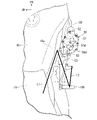
<クラッチアクチュエータの配置>
図15~図17に示すように、クラッチアクチュエータ50は、車両側面視で、燃料タンク18右側のニーグリップ部18aの鉛直下方に配置されている。クラッチアクチュエータ50は、図16の車両上面視で、燃料タンク18右側のニーグリップ部18aよりも車幅方向外側に張り出して配置されている。図中線L1は、運転者の脚の大腿部、線L2は、膝から下の下腿部、線L3は、足首から先の足部をそれぞれイメージしている。
<Arrangement of clutch actuator>
As shown in FIGS. 15 to 17, the clutch actuator 50 is arranged vertically below the knee grip portion 18a on the right side of the fuel tank 18 as viewed from the side of the vehicle. The clutch actuator 50 is arranged to protrude outward in the vehicle width direction from the knee grip portion 18a on the right side of the fuel tank 18 when viewed from the top of the vehicle in FIG. In the figure, the line L1 represents the thigh of the driver's leg, the line L2 represents the lower leg below the knee, and the line L3 represents the foot from the ankle.
運転者の脚は、車両側面視で、ニーグリップ部18aから後下方へ斜めに下腿部L2を延ばし、ステップ18bに足部L3を載せる。クラッチアクチュエータ50は、ニーグリップ部18aよりも車幅方向外側に張り出す。クラッチアクチュエータ50は、車両側面視で運転者の脚の下腿部L2を前方に避けた配置となる。これにより、運転者の脚の配置スペースに対するクラッチアクチュエータ50の干渉が抑えられる。クラッチアクチュエータ50は、運転者が脚を伸ばして足部L3を着地させた場合にも、車両側面視で運転者の脚の下腿部L2を前方に避けた配置となる。この点でも、運転者の脚の配置スペースに対するクラッチアクチュエータ50の干渉が抑えられる。
As for the driver's leg, when viewed from the side of the vehicle, the lower leg L2 extends obliquely rearward and downward from the knee grip portion 18a, and the foot L3 is placed on the step 18b. The clutch actuator 50 protrudes outward in the vehicle width direction from the knee grip portion 18a. The clutch actuator 50 is arranged to avoid the crus L2 of the driver's legs forward when viewed from the side of the vehicle. This suppresses interference of the clutch actuator 50 with the arrangement space of the driver's legs. Clutch actuator 50 is positioned so as to avoid forward lower leg L2 of the driver's leg when viewed from the side of the vehicle even when the driver extends his leg and lands foot L3. In this respect as well, the interference of the clutch actuator 50 with the arrangement space of the driver's legs is suppressed.
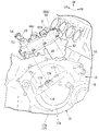
図17を参照し、右カバー17aは、以下の範囲を、車幅方向外側に膨出した膨出部17bとしている。前記範囲は、車両側面視でクラッチ装置26と同軸の円形の範囲である。膨出部17bにおける後上方に臨む部位には、カバー凹部17cが形成されている。カバー凹部17cは、残余の部位に対して外側面を車幅方向内側に変化させる。カバー凹部17cは、車両側面視で半円形状をなしている。
Referring to FIG. 17, the right cover 17a has the following range as a bulging portion 17b that bulges outward in the vehicle width direction. The range is a circular range coaxial with the clutch device 26 when viewed from the side of the vehicle. A cover concave portion 17c is formed in a portion of the bulging portion 17b facing rearward and upward. The cover recessed portion 17c changes the outer surface inward in the vehicle width direction with respect to the remaining portion. The cover recess 17c has a semicircular shape when viewed from the side of the vehicle.
カバー凹部17cの前記半円形状の弦部分は、車両側面視でレリーズシャフト53の軸方向と直交する直線状に形成されている。この弦部分は、膨出部17bの外側面を段差状に変化させる段差部17dを形成している。段差部17dは、車両側面視で後ろ下がりに傾斜している。段差部17dには、レリーズシャフト53の上部が斜め上後方に突出している。レリーズシャフト53は、カバー凹部17cの段差部17dを貫通して、カバー外側に突出している。クラッチアクチュエータ50は、カバー凹部17cに入り込むように配置された状態で、右カバー17aに取り付けられている。
The semicircular chord portion of the cover recess 17c is formed in a straight line perpendicular to the axial direction of the release shaft 53 when viewed from the side of the vehicle. This chord portion forms a stepped portion 17d that changes the outer surface of the bulging portion 17b in a stepped manner. The stepped portion 17d is inclined rearwardly downward when viewed from the side of the vehicle. The upper portion of the release shaft 53 protrudes obliquely upward and rearward from the stepped portion 17d. The release shaft 53 penetrates the stepped portion 17d of the cover concave portion 17c and protrudes outside the cover. The clutch actuator 50 is attached to the right cover 17a so as to be inserted into the cover recess 17c.
<レリーズシャフト>
図6~図8に示すように、レリーズシャフト53は、クラッチアクチュエータ50からの入力と、乗員の操作による入力と、を個別に受けて回動可能とするために、複数の要素に分割されている。
レリーズシャフト53は、上部を構成する上部レリーズシャフト61と、下部を構成する下部レリーズシャフト62と、中間レリーズシャフト63と、を備えている。中間レリーズシャフト63は、上部レリーズシャフト61の下端部と下部レリーズシャフト62の上端部とに跨って配置される。
<Release shaft>
As shown in FIGS. 6 to 8, the release shaft 53 is divided into a plurality of elements so as to be rotatable by separately receiving the input from the clutch actuator 50 and the input by the operation of the passenger. there is
The release shaft 53 includes an upper release shaft 61 forming an upper portion, a lower release shaft 62 forming a lower portion, and an intermediate release shaft 63 . The intermediate release shaft 63 is arranged across the lower end of the upper release shaft 61 and the upper end of the lower release shaft 62 .
上部レリーズシャフト61は、円柱状をなしている。上部レリーズシャフト61は、ギヤケース59の上ボス部59bに回転可能に支持されている。上部レリーズシャフト61は、上端部がギヤケース59の外側に突出している。上部レリーズシャフト61の上端部には、従動クラッチレバー54が一体回転可能に支持されている。従動クラッチレバー54には、リターンスプリング54sが取り付けられている。リターンスプリング54sは、クラッチ操作子の操作による回動(クラッチ切断方向の回動)とは逆方向の付勢力を従動クラッチレバー54に付与する。
The upper release shaft 61 has a cylindrical shape. The upper release shaft 61 is rotatably supported by the upper boss portion 59b of the gear case 59. As shown in FIG. An upper end portion of the upper release shaft 61 protrudes outside the gear case 59 . A driven clutch lever 54 is supported by the upper end of the upper release shaft 61 so as to be integrally rotatable. A return spring 54 s is attached to the driven clutch lever 54 . The return spring 54s applies an urging force to the driven clutch lever 54 in a direction opposite to the rotation (rotation in the clutch disengaging direction) due to the operation of the clutch operator.
下部レリーズシャフト62は、円柱状をなしている。下部レリーズシャフト62は、下部が右カバー17aの内側に回転可能に支持されている。下部レリーズシャフト62の下部は、ギヤケース59内に臨んでいる。この下部には、レリーズ機構38の偏心カム部38aが形成されている。下部レリーズシャフト62の下端部には、下部リターンスプリング62sが取り付けられている。下部リターンスプリング62sは、クラッチ切断方向の回動とは逆方向の付勢力を下部レリーズシャフト62に付与する。
The lower release shaft 62 has a cylindrical shape. A lower portion of the lower release shaft 62 is rotatably supported inside the right cover 17a. A lower portion of the lower release shaft 62 faces the inside of the gear case 59 . An eccentric cam portion 38a of the release mechanism 38 is formed in the lower portion. A lower return spring 62 s is attached to the lower end of the lower release shaft 62 . The lower return spring 62s applies an urging force to the lower release shaft 62 in a direction opposite to the rotation in the clutch disengaging direction.
上部レリーズシャフト61の下端部には、断面扇形をなして軸方向に延びる手動操作側カム61bが設けられている。
下部レリーズシャフト62の上端部には、断面扇形をなして軸方向に延びるクラッチ側カム62bが設けられている。クラッチ側カム62bは、周方向又は軸方向で手動操作側カム61bを避けた範囲に設けられている。
The lower end of the upper release shaft 61 is provided with a manual operation side cam 61b extending in the axial direction and having a fan-shaped cross section.
At the upper end of the lower release shaft 62, a clutch-side cam 62b extending in the axial direction and having a fan-shaped cross section is provided. The clutch side cam 62b is provided in a range that avoids the manual operation side cam 61b in the circumferential direction or the axial direction.
上部レリーズシャフト61の下端部(手動操作側カム61b)と、下部レリーズシャフト62の上端部(クラッチ側カム62b)とは、互いに周方向で避けつつ軸方向位置をラップさせている。又は、手動操作側カム61bとクラッチ側カム62bとは、互いに軸方向で避けつつ周方向位置をラップさせている。これにより、手動操作側カム61bの周方向一側面61b1で、クラッチ側カム62bの周方向他側面62b2を押圧し、下部レリーズシャフト62を回転させることが可能である(図9B、図10B参照)。
The lower end of the upper release shaft 61 (manual operation side cam 61b) and the upper end of the lower release shaft 62 (clutch side cam 62b) overlap each other in the axial direction while avoiding each other in the circumferential direction. Alternatively, the manual operation side cam 61b and the clutch side cam 62b overlap each other in the circumferential direction while avoiding each other in the axial direction. As a result, the one circumferential side surface 61b1 of the manual operation side cam 61b presses the other circumferential side surface 62b2 of the clutch side cam 62b, and the lower release shaft 62 can be rotated (see FIGS. 9B and 10B). .
手動操作側カム61bの周方向他側面61b2と、クラッチ側カム62bの周方向一側面62b1とは、周方向又は軸方向で互いに離間している。これにより、クラッチ側カム62bにクラッチアクチュエータ50からの入力があった場合には、上部レリーズシャフト61から独立して、下部レリーズシャフト62が回転可能である(図9A、図10A参照)。
The other circumferential side surface 61b2 of the manual operation side cam 61b and the one circumferential side surface 62b1 of the clutch side cam 62b are separated from each other in the circumferential direction or the axial direction. Accordingly, when the clutch-side cam 62b receives an input from the clutch actuator 50, the lower release shaft 62 can rotate independently of the upper release shaft 61 (see FIGS. 9A and 10A).
中間レリーズシャフト63は、円筒状をなしている。中間レリーズシャフト63は、上部レリーズシャフト61の下端部と、下部レリーズシャフト62の上端部と、の係合部分(上下シャフト係合部)を挿通可能である。中間レリーズシャフト63には、被動ギヤ63aが一体回転可能に支持されている。
中間レリーズシャフト63には、断面扇形をなして軸方向に延びる制御操作側カム63bが設けられている。
The intermediate release shaft 63 has a cylindrical shape. The intermediate release shaft 63 can be inserted through an engaging portion (upper and lower shaft engaging portion) between the lower end portion of the upper release shaft 61 and the upper end portion of the lower release shaft 62 . A driven gear 63a is supported by the intermediate release shaft 63 so as to be rotatable therewith.
The intermediate release shaft 63 is provided with a control operation side cam 63b extending in the axial direction and having a fan-shaped cross section.
中間レリーズシャフト63および被動ギヤ63aは、クラッチアクチュエータ50の他の構成部品に対する接触を抑えている。具体的に、中間レリーズシャフト63は、ギヤケース59に支持する軸受けの他には、以下の部位に内周部を接触させるのみである。その部位とは、上部レリーズシャフト61の下端部(手動操作側カム61b)、および下部レリーズシャフト62の上端部(クラッチ側カム62b)である。
中間レリーズシャフト63の制御操作側カム63bは、以下の部位に対して、軸方向でクリアランスを空けて係合している。その部位とは、上部レリーズシャフト61の手動操作側カム61b、および下部レリーズシャフト62のクラッチ側カム62bである。
また、被動ギヤ63aは、第二小径ギヤ58bにギヤ歯を接触させるのみである。これにより、制御ギヤである被動ギヤ63aのフリクションを極力低減し、レリーズシャフト53の制御の精度を向上させている。
Intermediate release shaft 63 and driven gear 63 a prevent contact with other components of clutch actuator 50 . Specifically, the intermediate release shaft 63 only contacts the bearings supported by the gear case 59, as well as the following parts. The parts are the lower end of the upper release shaft 61 (manual operation side cam 61b) and the upper end of the lower release shaft 62 (clutch side cam 62b).
The control operation side cam 63b of the intermediate release shaft 63 is engaged with the following parts with a clearance in the axial direction. These parts are the manual operation side cam 61b of the upper release shaft 61 and the clutch side cam 62b of the lower release shaft 62. As shown in FIG.
In addition, the driven gear 63a only brings the gear teeth into contact with the second small-diameter gear 58b. As a result, the friction of the driven gear 63a, which is the control gear, is reduced as much as possible, and the control accuracy of the release shaft 53 is improved.
中間レリーズシャフト63の制御操作側カム63bと、下部レリーズシャフト62のクラッチ側カム62bとは、互いに周方向で避けつつ軸方向位置をラップさせている。又は、制御操作側カム63bとクラッチ側カム62bとは、互いに軸方向で避けつつ周方向位置をラップさせている。これにより、制御操作側カム63bの周方向一側面63b1でクラッチ側カム62bの周方向他側面62b2を押圧し、下部レリーズシャフト62を回転させることが可能である。
The control operation side cam 63b of the intermediate release shaft 63 and the clutch side cam 62b of the lower release shaft 62 overlap each other in the axial direction while avoiding each other in the circumferential direction. Alternatively, the control operation side cam 63b and the clutch side cam 62b overlap each other in the circumferential direction while avoiding each other in the axial direction. As a result, the one circumferential side surface 63b1 of the control operation side cam 63b presses the other circumferential side surface 62b2 of the clutch side cam 62b, and the lower release shaft 62 can be rotated.
また、制御操作側カム63bは、上部レリーズシャフト61の手動操作側カム61bを、軸方向又は径方向で避けて配置されている。これにより、クラッチアクチュエータ50からの入力をクラッチ側カム62bに伝達する際、上部レリーズシャフト61から独立して、下部レリーズシャフト62を回転可能である。また、手動操作があった場合には、上部レリーズシャフト61を制御側の中間レリーズシャフト63から独立して回転可能である。
Also, the control operation side cam 63b is arranged to avoid the manual operation side cam 61b of the upper release shaft 61 in the axial direction or radial direction. This allows the lower release shaft 62 to rotate independently of the upper release shaft 61 when transmitting the input from the clutch actuator 50 to the clutch-side cam 62b. Further, when there is a manual operation, the upper release shaft 61 can be rotated independently of the intermediate release shaft 63 on the control side.
制御操作側カム63bの周方向他側面63b2と、クラッチ側カム62bの周方向一側面62b1とは、周方向で互いに離間している。これにより、クラッチ側カム62bに手動操作側カム63bからの入力があった場合には、中間レリーズシャフト63から独立して、下部レリーズシャフト62が回転可能である。
The other circumferential side surface 63b2 of the control operation side cam 63b and the one circumferential side surface 62b1 of the clutch side cam 62b are separated from each other in the circumferential direction. As a result, the lower release shaft 62 can rotate independently of the intermediate release shaft 63 when the clutch side cam 62b receives an input from the manual operation side cam 63b.
図11、図17を参照し、クラッチアクチュエータ50は、上部レリーズシャフト61および中間レリーズシャフト63を、ギヤケース59で回動可能に保持している。クラッチアクチュエータ50は、上部レリーズシャフト61および中間レリーズシャフト63を含んで、一体のアクチュエータユニット50Aを構成している。
11 and 17, clutch actuator 50 rotatably holds upper release shaft 61 and intermediate release shaft 63 with gear case 59 . Clutch actuator 50 includes upper release shaft 61 and intermediate release shaft 63 to form an integrated actuator unit 50A.
下部レリーズシャフト62は、右カバー17aに回転可能に保持されている。右カバー17aの前記カバー凹部17cの段差部17dには、開口部17eが設けられるとともに、ギヤケース59の締結部17fが設けられる。開口部17eからは、下部レリーズシャフト62の上端部が突出する。ギヤケース59における前記カバー凹部17cの段差部17dとの対向部分には、開口部59cが設けられる。開口部59cは、下部レリーズシャフト62の上端部をギヤケース59内に臨ませる。
The lower release shaft 62 is rotatably held by the right cover 17a. An opening 17e and a fastening portion 17f of the gear case 59 are provided in the stepped portion 17d of the cover recess 17c of the right cover 17a. The upper end of the lower release shaft 62 protrudes from the opening 17e. An opening 59c is provided in a portion of the gear case 59 facing the stepped portion 17d of the recessed cover 17c. The opening 59 c allows the upper end of the lower release shaft 62 to face the inside of the gear case 59 .
係る構成において、アクチュエータユニット50Aを右カバー17aに取り付けると、直線状のレリーズシャフト53が構成される。レリーズシャフト53は、上部レリーズシャフト61、中間レリーズシャフト63および下部レリーズシャフト62が相互に連結されて構成される。
In such a configuration, when the actuator unit 50A is attached to the right cover 17a, a linear release shaft 53 is constructed. The release shaft 53 is configured by connecting an upper release shaft 61, an intermediate release shaft 63, and a lower release shaft 62 to each other.
実施形態のパワーユニットPUは、クラッチ装置26の断接操作を電気制御で行わずに運転者の操作で行うマニュアルクラッチ式のパワーユニットに対し、以下のように構成可能である。すなわち、パワーユニットPUは、右カバー17aおよびレリーズシャフト53を交換し、アクチュエータユニット50Aを後付けすることで構成可能である。このため、機種違いのパワーユニットに対しても、アクチュエータユニット50Aを取り付け可能である。このため、多機種間でアクチュエータユニット50Aを共有して、容易にセミオートマチックの変速システム(自動クラッチ式変速システム)を構成可能である。
The power unit PU of the embodiment can be configured as follows for a manual clutch type power unit in which the connecting and disconnecting operation of the clutch device 26 is not performed by electric control but by the driver's operation. That is, the power unit PU can be configured by replacing the right cover 17a and the release shaft 53 and retrofitting the actuator unit 50A. Therefore, the actuator unit 50A can be attached to a power unit of a different model. Therefore, it is possible to easily configure a semi-automatic transmission system (automatic clutch type transmission system) by sharing the actuator unit 50A among many models.
<クラッチ制御>
次に、実施形態のクラッチ制御について、図12のグラフを参照して説明する。図12のグラフは、前記オートモードM1におけるクラッチ特性をイメージしている。図12のグラフにおいて、縦軸は従動クラッチレバー54に付与されるトルク(Nm)およびクラッチ容量(%)、横軸は従動クラッチレバー54の作動角(deg)をそれぞれ示している。従動クラッチレバー54の作動角は、下部レリーズシャフト62の作動角である。
<Clutch control>
Next, clutch control according to the embodiment will be described with reference to the graph of FIG. The graph in FIG. 12 represents the clutch characteristics in the auto mode M1. In the graph of FIG. 12 , the vertical axis indicates the torque (Nm) applied to the driven clutch lever 54 and the clutch capacity (%), and the horizontal axis indicates the operating angle (deg) of the driven clutch lever 54 . The operating angle of the driven clutch lever 54 is the operating angle of the lower release shaft 62 .
従動クラッチレバー54のトルクは、下部レリーズシャフト62の発生トルクである。このトルクは、以下の一次トルク値に、減速機構51の減速比を乗じて算出されるトルク値に相当する。前記一次トルク値は、モータ52への供給電流とモータ52が発生するトルクとの相関から、モータ52への供給電流値に基づき得られる。
以下、従動クラッチレバー54のトルクを従動クラッチレバートルクという。従動クラッチレバー作動角と従動クラッチレバートルクとの相関をグラフ中線L11で示す。従動クラッチレバー作動角とクラッチ容量との相関をグラフ中線L12で示す。線L11は、マニュアル操作が介入しない状態でクラッチ装置26を断接する際の、クラッチアクチュエータ50の出力値(基準出力値)を示す線でもある。
The torque of the driven clutch lever 54 is the torque generated by the lower release shaft 62 . This torque corresponds to a torque value calculated by multiplying the following primary torque value by the speed reduction ratio of the speed reduction mechanism 51 . The primary torque value is obtained based on the current value supplied to the motor 52 from the correlation between the current supplied to the motor 52 and the torque generated by the motor 52 .
Hereinafter, the torque of the driven clutch lever 54 will be referred to as driven clutch lever torque. A line L11 in the graph indicates the correlation between the driven clutch lever operating angle and the driven clutch lever torque. A line L12 in the graph indicates the correlation between the driven clutch lever operating angle and the clutch capacity. The line L11 is also a line indicating the output value (reference output value) of the clutch actuator 50 when the clutch device 26 is engaged and disengaged without intervention of manual operation.
ノーマルクローズクラッチのオートモードM1において、従動クラッチレバートルク(モータ出力)が「0」のとき、クラッチ装置26に対する操作入力(切断側への入力)はなく、クラッチ容量は100%となる。すなわち、クラッチ装置26は、接続状態を維持する。この状態は、図12の横軸の領域Aに相当する。領域Aは、従動クラッチレバー54の遊び領域である。領域Aでは、モータ出力がなく、従動クラッチレバートルクは「0」で推移する。領域Aでは、クラッチ装置26の作動がなく、クラッチ容量は100%で推移する。
In the auto mode M1 of the normally closed clutch, when the driven clutch lever torque (motor output) is "0", there is no operation input (disengagement side input) to the clutch device 26 and the clutch capacity is 100%. That is, the clutch device 26 maintains the connected state. This state corresponds to region A on the horizontal axis of FIG. A region A is a play region of the driven clutch lever 54 . In area A, there is no motor output and the driven clutch lever torque remains "0". In area A, the clutch device 26 is not operated and the clutch capacity remains at 100%.
図8を併せて参照し、領域Aでは、レリーズシャフト53の手動操作側カム61bの周方向一側面61b1が、クラッチ側カム62bの周方向他側面62b2を押圧しない。このとき、手動操作側カム61bは、リターンスプリング54sの付勢力により、クラッチ側カム62bから離間している(図8中鎖線で示す)。領域Aでは、従動クラッチレバー54は、手動操作側カム61bが、クラッチ側カム62bに対して、図中角度A1だけ接近離反可能な遊び状態にある。例えば、領域Aでは、制御操作側カム63bの周方向一側面63b1が、クラッチ側カム62bの周方向他側面62b2に当接した状態にある。
Also referring to FIG. 8, in region A, the one circumferential side surface 61b1 of the manual operation side cam 61b of the release shaft 53 does not press the other circumferential side surface 62b2 of the clutch side cam 62b. At this time, the manual operation side cam 61b is separated from the clutch side cam 62b by the biasing force of the return spring 54s (indicated by the dashed line in FIG. 8). In the region A, the driven clutch lever 54 is in a play state in which the manual operation side cam 61b can move toward and away from the clutch side cam 62b by an angle A1 in the figure. For example, in region A, one circumferential side surface 63b1 of the control operation side cam 63b is in contact with the other circumferential side surface 62b2 of the clutch side cam 62b.
図12を参照し、従動クラッチレバー作動角が増加して遊び領域Aを過ぎると、従動クラッチレバー作動角が半クラッチ領域Bに移行する。半クラッチ領域Bでは、モータ52の作動により、従動クラッチレバートルクが増加を開始する。
Referring to FIG. 12, when the driven clutch lever operating angle increases and passes through the play area A, the driven clutch lever operating angle shifts to the half-clutch area B. In the half-clutch region B, the driven clutch lever torque starts increasing due to the operation of the motor 52 .
図9Aを併せて参照し、半クラッチ領域Bでは、制御操作側カム63bがクラッチ側カム62bを押圧して、下部レリーズシャフト62を回転させる。従動クラッチレバートルクが増加すると、レリーズ機構38がクラッチ装置26をリフト作動させ、クラッチ容量を減少させる。すなわち、クラッチ装置26は、一部の動力伝達を可能とした半クラッチ状態となる。図12中符号SPは、遊び領域Aから半クラッチ領域Bに切り替わる作動の開始位置(作動開始位置)を示す。半クラッチ領域Bにおいて、マニュアル操作が介入すると、手動操作側カム61bがクラッチ側カム62bに当接する。このとき、手動操作側カム61bは、制御操作側カム63bと協働して、下部レリーズシャフト62を回転させる(図9B参照)。
Also referring to FIG. 9A, in the half-clutch region B, the control operation side cam 63b presses the clutch side cam 62b, causing the lower release shaft 62 to rotate. As the driven clutch lever torque increases, the release mechanism 38 lifts the clutch device 26 to reduce the clutch capacity. That is, the clutch device 26 is in a half-clutch state in which partial power transmission is possible. Symbol SP in FIG. 12 indicates the start position (operation start position) of the operation where the play area A is switched to the half-clutch area B. FIG. In the half-clutch region B, when the manual operation intervenes, the manual operation side cam 61b contacts the clutch side cam 62b. At this time, the manual operation side cam 61b cooperates with the control operation side cam 63b to rotate the lower release shaft 62 (see FIG. 9B).
図12を参照し、半クラッチ領域Bにおいて、従動クラッチレバートルクは、従動クラッチレバー作動角の増加に伴い急峻に増加し、クラッチ装置26を切断側に作動させる。例えば、半クラッチ領域Bの初期には、不図示のクラッチジャダースプリング反力の影響がある。これにより、半クラッチ領域Bの初期には、従動クラッチレバー作動角の増加に対する従動クラッチレバートルクの増加を緩やかにした減速領域B1が設定される。
半クラッチ領域Bにおいて、クラッチ容量は、従動クラッチレバートルクの増加に反比例するように、従動クラッチレバー作動角の増加に伴い急峻に減少する。半クラッチ領域Bの初期の減速領域B1において、クラッチ容量は、従動クラッチレバートルクの増加が緩やかなることに伴い、減少を緩やかにする。
Referring to FIG. 12, in the half-clutch region B, the driven clutch lever torque sharply increases as the driven clutch lever operating angle increases, causing the clutch device 26 to operate to the disengagement side. For example, at the beginning of the half-clutch region B, there is an influence of clutch judder spring reaction force (not shown). As a result, at the beginning of the half-clutch region B, a deceleration region B1 is set in which the increase in the driven clutch lever torque with respect to the increase in the driven clutch lever operating angle is moderate.
In the half-clutch region B, the clutch capacity sharply decreases as the driven clutch lever operating angle increases so as to be inversely proportional to the increase in driven clutch lever torque. In the initial deceleration region B1 of the half-clutch region B, the clutch capacity slows down as the driven clutch lever torque increases slowly.
従動クラッチレバー作動角が、半クラッチ領域Bの終点であるタッチポイントTPを過ぎると、従動クラッチレバートルクの増加は、減速領域B1よりも緩やかになる。従動クラッチレバー作動角におけるタッチポイントTP以降の領域は、例えば、クラッチ容量が「0」相当のまま推移するクラッチ切断領域Cとなる。クラッチ切断領域Cは、例えば、従動クラッチレバー54等が機械的な作動限界位置まで作動するための作動余裕領域である。クラッチ切断領域Cでは、従動クラッチレバートルクが微増する。この増加分は、クラッチ装置26のリフト部品の移動に伴うクラッチスプリング荷重の増加分に相当する。図12中符号EPは、クラッチ切断領域Cの終点であるフルリフト位置を示す。
When the driven clutch lever operating angle passes the touch point TP, which is the end point of the half-clutch area B, the increase in the driven clutch lever torque becomes more moderate than in the deceleration area B1. The region after the touch point TP in the driven clutch lever actuation angle is, for example, a clutch disengagement region C where the clutch capacity remains equivalent to "0". The clutch disengagement region C is, for example, an operation margin region for the driven clutch lever 54 and the like to operate up to the mechanical operation limit position. In the clutch disengagement region C, the driven clutch lever torque slightly increases. This increment corresponds to the increment of the clutch spring load accompanying the movement of the lift component of the clutch device 26 . Symbol EP in FIG.
例えば、クラッチ切断領域Cの中間には、待機位置DPが設定される。待機位置DPでは、以下の従動クラッチレバートルクが付与される。このときの従動クラッチレバートルクは、クラッチ装置26が接続を開始するタッチポイントTPのトルクよりも若干高い。タッチポイントTPでは、作動誤差により若干のトルク伝達が生じることがある。これに対し、待機位置DPのトルクまで従動クラッチレバートルクを付与することで、クラッチ装置26のトルク伝達は完全に遮断される。また、待機位置DPでは、フルリフト位置EPに対して若干低い従動クラッチレバートルクが付与されることで、クラッチ装置26の無効詰めを行うことが可能となる。すなわち、待機位置DPでは、クラッチ装置26における各部のガタや作動反力のキャンセル等が可能となり、クラッチ装置26の接続時の作動応答性を高めることができる。
For example, a standby position DP is set in the middle of the clutch disengagement region C. At the standby position DP, the following driven clutch lever torque is applied. The driven clutch lever torque at this time is slightly higher than the torque at the touch point TP at which the clutch device 26 starts to engage. At the touch point TP, some torque transfer may occur due to operating errors. On the other hand, by applying the driven clutch lever torque up to the torque of the standby position DP, the torque transmission of the clutch device 26 is completely interrupted. Further, at the standby position DP, a driven clutch lever torque slightly lower than that at the full lift position EP is applied, so that the clutch device 26 can be disabled. That is, at the standby position DP, it is possible to cancel the looseness of each part of the clutch device 26 and the reaction force of the action, and the like, and the action response when the clutch device 26 is engaged can be enhanced.
なお、クラッチ装置26が接続状態から切断側へ作動する際、作動開始位置SPおよびタッチポイントTPは以下のように定まる。すなわち、従動クラッチレバートルクが立ち上がるポイント(半クラッチ領域Bの始点)が作動開始位置SPである。また、クラッチ装置26が完全に切れるポイント(半クラッチ領域Bの終点)がタッチポイントTPである。
逆に、クラッチ装置26が切断状態から接続側へ作動する際、タッチポイントTPおよび作動開始位置SPは以下のように定まる。すなわち、クラッチ装置26が接続し始めるポイントがタッチポイントTPである。また、クラッチ装置26が完全に接続するポイントが作動開始位置SPである。
When the clutch device 26 operates from the connected state to the disengaged side, the operation start position SP and the touch point TP are determined as follows. That is, the point at which the driven clutch lever torque rises (the starting point of the half-clutch region B) is the operation start position SP. A touch point TP is the point at which the clutch device 26 is completely disengaged (the end point of the half-clutch region B).
Conversely, when the clutch device 26 operates from the disengaged state to the engaged side, the touch point TP and the operation start position SP are determined as follows. That is, the touch point TP is the point at which the clutch device 26 starts to engage. Further, the point at which the clutch device 26 is completely connected is the operation start position SP.
図13を参照し、半クラッチ領域Bにおいて、モータ52の駆動は、リフト荷重に基づき制御される。
係る制御では、まず、クラッチスプリング37の弾発力に基づき、予めクラッチスプリング荷重を設定する。次に、従動クラッチレバートルクに応じて、クラッチ装置26に作用するリフト荷重(クラッチスプリング荷重に抗する操作荷重)を推定する。そして、クラッチスプリング荷重からリフト荷重を減じた荷重を、実際にクラッチ装置26に作用させるクラッチ押付荷重とする。
Referring to FIG. 13, in half-clutch region B, the drive of motor 52 is controlled based on the lift load.
In such control, first, based on the elastic force of the clutch spring 37, the clutch spring load is set in advance. Next, the lift load acting on the clutch device 26 (the operation load against the clutch spring load) is estimated according to the driven clutch lever torque. Then, the load obtained by subtracting the lift load from the clutch spring load is used as the clutch pressing load that actually acts on the clutch device 26 .
クラッチ容量は、「クラッチ押付荷重/クラッチスプリング荷重」で求められる。クラッチ容量が目標値となるように、モータ52への供給電力を制御し、従動クラッチレバートルクひいてはリフト荷重を制御する。前記作動開始位置SPおよびタッチポイントTPの各々におけるモータ電流値およびレバー作動角は、予め既定値に設定する。あるいは、前記モータ電流値およびレバー作動角は、後述するように、自動二輪車1の電源オン時またはオフ時等に学習制御によって設定する。
Clutch capacity is determined by "clutch pressing load/clutch spring load". The electric power supplied to the motor 52 is controlled so that the clutch capacity becomes the target value, and the driven clutch lever torque and thus the lift load are controlled. A motor current value and a lever operation angle at each of the operation start position SP and the touch point TP are set to predetermined values in advance. Alternatively, the motor current value and the lever operating angle are set by learning control when the power of the motorcycle 1 is turned on or off, as will be described later.
センシング構成の一例として、以下の構成が挙げられる。すなわち、モータ制御装置(クラッチコントロール部40C)内に電流センサ40bを設け、この検出値をモータトルクに換算し、さらに従動クラッチレバートルク(クラッチ操作トルク)に換算することが挙げられる。
An example of the sensing configuration is the following configuration. That is, a current sensor 40b is provided in the motor control device (clutch control section 40C), and the detected value is converted into motor torque, and further converted into driven clutch lever torque (clutch operation torque).
図13に示すように、半クラッチ領域Bにおいて、前記クラッチレバーの操作(マニュアル操作)の介入があると、以下の作用がある。すなわち、予め設定した従動クラッチレバートルクの相関線L11に対し、従動クラッチレバートルクの実測値が減少する(図中F部参照)。このとき、従動クラッチレバートルクの減少量が予め定めた閾値d1を越えると、マニュアル操作の介入があったものと判定し、予め定めたマニュアル操作介入制御に移行する。
As shown in FIG. 13, when the clutch lever is operated (manually operated) in the half-clutch region B, the following effects occur. That is, the measured value of the driven clutch lever torque decreases with respect to the preset correlation line L11 of the driven clutch lever torque (see part F in the figure). At this time, when the amount of decrease in the driven clutch lever torque exceeds a predetermined threshold value d1, it is determined that manual operation intervention has occurred, and the control shifts to predetermined manual operation intervention control.
マニュアル操作介入制御では、例えば、マニュアル操作介入を検知してから、従動クラッチレバー作動角の増加分が予め定めた角度以上となるまで、以下のように制御する。すなわち、従動クラッチレバートルクが閾値d1だけ減少した後のトルクd2を維持するように、モータ52をフィードバック制御する。このときの電流制御中は、タッチポイントTP以降では角度に応じた電流制限を設けている。このため、電流制御の途中でモータ出力はほぼ0となる。その時の負荷が十分に低いので、マニュアル介入したと判断する。これにより、前記クラッチレバーの操作後に、急にモータ52からのトルクが無くなることによる違和感を抑止することができる。従動クラッチレバー作動角の増加分が規定角度以上となった後は、徐々に従動クラッチレバートルクを減少させる(図中G部参照)。これにより、前記違和感を抑えつつ、モータ52を駆動し続けることによる電力消費を抑えることができる。
In the manual operation intervention control, for example, after manual operation intervention is detected, the following control is performed until the increment of the driven clutch lever operating angle reaches or exceeds a predetermined angle. That is, the motor 52 is feedback-controlled so that the torque d2 after the driven clutch lever torque is reduced by the threshold value d1 is maintained. During the current control at this time, the current is limited according to the angle after the touch point TP. Therefore, the motor output becomes almost 0 during the current control. Since the load at that time is sufficiently low, it is determined that manual intervention has occurred. As a result, it is possible to prevent a feeling of strangeness due to sudden loss of torque from the motor 52 after the clutch lever is operated. After the increment of the driven clutch lever operating angle becomes equal to or greater than the specified angle, the driven clutch lever torque is gradually decreased (see G section in the figure). As a result, it is possible to suppress power consumption due to continuous driving of the motor 52 while suppressing the uncomfortable feeling.
クラッチ切断領域Cにおいて、モータ52の駆動は、レバー位置(角度)に基づき制御される。
前述のように、クラッチ切断領域Cでは、クラッチ装置26のリフトに伴う従動クラッチレバートルクの増加が少ない。このため、クラッチ切断領域Cでは、従動クラッチレバー作動角に基づき、モータ52への供給電力を制御する。これにより、クラッチ装置26が接続を開始するタッチポイントTP以降において、クラッチ装置26の切れ量をより細かく制御することが可能となる。
In the clutch disengagement region C, the drive of the motor 52 is controlled based on the lever position (angle).
As described above, in the clutch disengagement region C, the increase in the driven clutch lever torque accompanying the lift of the clutch device 26 is small. Therefore, in the clutch disengagement region C, the electric power supplied to the motor 52 is controlled based on the driven clutch lever operating angle. As a result, it is possible to more finely control the disengagement amount of the clutch device 26 after the touch point TP at which the clutch device 26 starts to be connected.
センシング構成の一例として、以下の構成が挙げられる。すなわち、第一リダクション軸57および第二リダクション軸58に、それぞれ第一回転角度センサ57dおよび第二回転角度センサ58dを設ける。そして、これら各センサの検出値を、従動クラッチレバー作動角(クラッチ操作角)に換算することが挙げられる。第一回転角度センサ57dおよび第二回転角度センサ58dは、フェール用に一対設けているが、これらの何れか一方のみとしてもよい。
An example of the sensing configuration is the following configuration. That is, the first reduction shaft 57 and the second reduction shaft 58 are provided with a first rotation angle sensor 57d and a second rotation angle sensor 58d, respectively. Then, the values detected by these sensors can be converted into driven clutch lever operating angles (clutch operating angles). A pair of the first rotation angle sensor 57d and the second rotation angle sensor 58d are provided for failure, but only one of them may be provided.
図13に示すように、クラッチ切断領域Cにおいて、前記クラッチレバーの操作(マニュアル操作)の介入があると、以下の作用がある。すなわち、予め設定した従動クラッチレバートルクの相関線L11に対し、従動クラッチレバートルクの実測値が減少する(図中H部参照)。
As shown in FIG. 13, when the clutch lever is operated (manually operated) in the clutch disengagement region C, the following effects occur. That is, the measured value of the driven clutch lever torque decreases with respect to the preset correlation line L11 of the driven clutch lever torque (see section H in the figure).
図10Aを併せて参照し、例えば、オートモードM1において、制御操作側カム63bがクラッチ側カム62bに付与するトルクは、待機位置DPに至るまでのトルクを上限とされる。クラッチ側カム62bが待機位置DPを越えてフルリフト位置EPに至るまでのトルクは、前記クラッチレバーを握り込むマニュアル操作が介入した場合に付与される。このとき、待機位置DPを越えるだけのトルクが、手動操作側カム61bからクラッチ側カム62bに付与される(図10B参照)。このとき、制御操作側カム63bはクラッチ側カム62bから離間し、モータ出力は実質0となる。
Also referring to FIG. 10A, for example, in the auto mode M1, the upper limit of the torque applied by the control operation side cam 63b to the clutch side cam 62b is the torque up to the standby position DP. The torque until the clutch-side cam 62b exceeds the standby position DP and reaches the full-lift position EP is applied when the manual operation of gripping the clutch lever intervenes. At this time, a torque that exceeds the standby position DP is applied from the manual operation side cam 61b to the clutch side cam 62b (see FIG. 10B). At this time, the control operation side cam 63b is separated from the clutch side cam 62b, and the motor output becomes substantially zero.
待機位置DPに至る手前であっても、従動クラッチレバー作動角がタッチポイントTPを越えたクラッチ切断領域Cにあると、以下の作用がある。すなわち、マニュアル操作の介入によって、従動クラッチレバートルクの実測値は実質0となる。したがって、クラッチ切断領域Cにおいて、従動クラッチレバートルクの実測値が実質0となる範囲に変化した場合には、マニュアル操作の介入があったものと判定する。そして、予め定めたマニュアル操作介入制御に移行する。
Even before reaching the standby position DP, if the driven clutch lever operating angle is in the clutch disengagement region C beyond the touch point TP, the following effects will occur. That is, the measured value of the driven clutch lever torque becomes substantially zero due to intervention of the manual operation. Therefore, when the measured value of the driven clutch lever torque changes to substantially 0 in the clutch disengagement region C, it is determined that manual intervention has occurred. Then, the control shifts to predetermined manual operation intervention control.
マニュアル操作介入制御では、例えば、マニュアル操作介入を検知してから従動クラッチレバー作動角の増加分が予め定めた角度以上となるまで、以下のように制御する。すなわち、従動クラッチレバー作動角が、実質的なクラッチ切断位置であるタッチポイントTPを維持するように、モータ出力を保持する。これにより、マニュアル操作の介入後にクラッチレバーが急に解放された場合にも、エンストの発生を抑止する。
In the manual operation intervention control, for example, the following control is performed from when the manual operation intervention is detected until the increment of the driven clutch lever operating angle reaches or exceeds a predetermined angle. That is, the motor output is maintained so that the driven clutch lever operating angle maintains the touch point TP, which is the substantial clutch disengagement position. As a result, even if the clutch lever is suddenly released after the intervention of the manual operation, the occurrence of the engine stall is suppressed.
このように、クラッチ装置26の状況に応じて、荷重(電流)制御と位置(角度)制御とを使い分けることで、より細やかなクラッチ制御(クラッチ装置26の状態や特性に応じた最適な制御)を行うことが可能となる。
実施形態では、従動クラッチレバー作動角(減速機構51のギヤ軸の回転角)を検出し、以下のように制御する。すなわち、予め設定した(又は学習した)タッチポイントTPまでの領域(半クラッチ領域B)では、電流値の基準を増した制御とした。タッチポイントTP以降の領域(クラッチ切断領域C)では、作動角の基準を増した制御とした。
In this way, by selectively using load (current) control and position (angle) control according to the state of the clutch device 26, finer clutch control (optimal control according to the state and characteristics of the clutch device 26) can be achieved. It is possible to do
In the embodiment, the driven clutch lever operating angle (the rotation angle of the gear shaft of the reduction mechanism 51) is detected and controlled as follows. In other words, in the region up to the preset (or learned) touch point TP (half-clutch region B), control is performed by increasing the current value reference. In the region after the touch point TP (clutch disengagement region C), the control was performed with an increased reference for the operating angle.
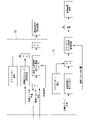
図18は、実施形態における半クラッチ領域Bとクラッチ切断領域Cとを切り替える切替制御に係る機能ブロック図である。
図中下段のブロック図では、半クラッチ領域Bにおけるモータ電流(クラッチ容量、荷重)の重み付けを増した制御として、以下の内容を示す。すなわち、予め定めた目標クラッチ容量に応じたモータ電流に、フリクション補正を加えて、目標電流値を求める。この目標電流値と現在クラッチ位置との関係から、マニュアル介入判断用電流制限を決定する。そして、半クラッチ制御中にクラッチ位置が切断領域に入ったら、マニュアル介入があったと判断する。図中符号71は、半クラッチ領域Bにおいて、クラッチ容量(荷重)に基づき、マニュアル介入判断用の情報を生成する第一情報生成部を示す。
FIG. 18 is a functional block diagram relating to switching control for switching between the half-clutch region B and the clutch-disengaged region C in the embodiment.
The block diagram in the lower part of the figure shows the following contents as the control in which the weight of the motor current (clutch capacity, load) in the half-clutch region B is increased. That is, a target current value is obtained by adding friction correction to a motor current corresponding to a predetermined target clutch capacity. Based on the relationship between the target current value and the current clutch position, the manual intervention determination current limit is determined. Then, when the clutch position enters the disengagement region during half-clutch control, it is determined that manual intervention has occurred. Reference numeral 71 in the figure denotes a first information generation section that generates information for manual intervention determination based on the clutch capacity (load) in the half-clutch region B. FIG.
図中上段のブロック図では、クラッチ切断領域Cにおけるクラッチ作動角(クラッチ位置)の重み付けを増した制御として、以下の内容を示す。すなわち、目標クラッチ位置と現在クラッチ位置との差に対し、さらにクラッチ作動速度を加味して、「速度/位置の偏差に応じた電流値(トルク)」を求める。これと並行して、目標クラッチ位置に応じて予め定めたベース電流に、フリクション補正を加えて、目標電流値を求める。この目標電流値と前記偏差に応じた電流値とを加えて、連続保持時電流制限を決定する。そして、クラッチ切断制御中に負荷電流が一定値以下になったら、マニュアル介入があったと判断する。図中符号72は、クラッチ切断領域Cにおいて、クラッチ位置に基づき、マニュアル介入判断用の情報を生成する第二情報生成部を示す。
In the upper block diagram of the figure, the following contents are shown as control with increased weighting of the clutch operating angle (clutch position) in the clutch disengagement region C. That is, the current value (torque) corresponding to the speed/position deviation is obtained by adding the clutch operating speed to the difference between the target clutch position and the current clutch position. In parallel with this, a target current value is obtained by adding friction correction to a base current predetermined according to the target clutch position. The target current value and the current value corresponding to the deviation are added to determine the current limit during continuous holding. Then, when the load current drops below a certain value during clutch disengagement control, it is determined that manual intervention has occurred. Reference numeral 72 in the figure denotes a second information generation section that generates information for manual intervention determination in the clutch disengagement region C based on the clutch position.
また、実施形態では、従動クラッチレバー作動角に対するモータ52の電流値(トルク値に換算)の変化を、予め定めたタイミングで学習(更新)する。これにより、クラッチ装置26の状況に応じた目標値(電流値)を設定する。この目標値とクラッチコントロール部40Cの電流センサ40bの検出値とに基づき、モータ52の駆動がフィードバック制御される。
In addition, in the embodiment, changes in the current value (converted to torque value) of the motor 52 with respect to the driven clutch lever operating angle are learned (updated) at predetermined timings. Thereby, a target value (current value) corresponding to the state of the clutch device 26 is set. Based on this target value and the detection value of the current sensor 40b of the clutch control section 40C, the drive of the motor 52 is feedback-controlled.
<制御基準値の補正>
次に、実施形態のタッチポイントTP等における電流と角度とを学習する制御について、図14のグラフを参照して説明する。図14のグラフは、図12、図13に示したクラッチ特性を示す相関線L11が変化する様を示す。この変化は、クラッチ板35の摩耗およびエンジン13の温度(例えば冷却水温)等に応じて生じる。図14において、縦軸は従動クラッチレバートルク(Nm)、横軸は従動クラッチレバー作動角(deg)をそれぞれ示している。
<Correction of control reference value>
Next, the control for learning the current and angle at the touch point TP etc. of the embodiment will be described with reference to the graph of FIG. The graph of FIG. 14 shows how the correlation line L11 indicating the clutch characteristics shown in FIGS. 12 and 13 changes. This change occurs depending on the wear of the clutch plate 35, the temperature of the engine 13 (for example, coolant temperature), and the like. In FIG. 14, the vertical axis indicates driven clutch lever torque (Nm), and the horizontal axis indicates driven clutch lever operating angle (deg).
実施形態では、例えば、自動二輪車1のメインスイッチ(電源)のオン時またはオフ時において、クラッチ容量制御の際の0点(作動開始位置SPおよびタッチポイントTP)を補正する。モータ52の電流制御では、温度変化がモータトルクに影響する。このため、相関線L11の高さが温度によって変化する(図中J参照)。そこで、例えば、エンジン温度が80度以上か否か(エンジン暖機後か否か)といった複数の温度範囲の各々で、0点の補正を行う。このときの0点はメモリに記憶し、次回のクラッチ容量制御に利用する。
In the embodiment, for example, when the main switch (power supply) of the motorcycle 1 is turned on or off, the zero point (operation start position SP and touch point TP) during clutch capacity control is corrected. In current control of the motor 52, temperature changes affect the motor torque. Therefore, the height of the correlation line L11 changes depending on the temperature (see J in the figure). Therefore, for example, 0 point correction is performed in each of a plurality of temperature ranges such as whether or not the engine temperature is 80 degrees or higher (whether or not the engine has been warmed up). The 0 point at this time is stored in the memory and used for the next clutch capacity control.
作動開始位置SPおよびタッチポイントTPの設定(学習)の手順の一例を説明する。まず、例えば、クラッチコントロール部40Cの電源オン時またはオフ時に、クラッチアクチュエータ50を作動させる。このとき、クラッチ装置26の切断までの電流値の変化を計測する。次に、遊び領域Aから半クラッチ領域Bに至る際の電流値の変化の傾き(変化率)を検出する。また、半クラッチ領域Bからクラッチ切断領域Cに至る際の電流値の変化の傾き(変化率)を検出する。前者の傾きが閾値以上となるポイントを作動開始位置SPとする。後者の傾きが閾値以下となるポイントをタッチポイントTPとする。
別案として、以下の部分を作動開始位置SPとして学習してもよい。その部分とは、クラッチ遊び領域からから電流をランプで増加させ、前記回転角度センサの角速度が加速したところから減速し始める部分(最高速度になる部分)である。
逆に、以下の部分をタッチポイントTPとして学習してもよい。その部分とは、クラッチ切断状態(領域で保持)からランプで電流を減少させ、前記回転角度センサの角速度が加速したところから減速し始める部分(最高速度になる部分)である。
An example of the procedure for setting (learning) the operation start position SP and the touch point TP will be described. First, for example, the clutch actuator 50 is operated when the power of the clutch control section 40C is turned on or off. At this time, the change in current value until the clutch device 26 is disengaged is measured. Next, the gradient (rate of change) of change in the current value from the play area A to the half-clutch area B is detected. In addition, the gradient (rate of change) of change in the current value from half-clutch region B to clutch disengagement region C is detected. The point at which the former inclination is equal to or greater than the threshold is defined as the operation start position SP. A touch point TP is defined as a point where the slope of the latter is equal to or less than the threshold.
Alternatively, the following portion may be learned as the operation start position SP. This portion is a portion where the current is ramped up from the clutch play area and the angular velocity of the rotation angle sensor accelerates and then decelerates (the maximum velocity).
Conversely, the following portions may be learned as touch points TP. This portion is a portion where the angular velocity of the rotation angle sensor starts decelerating from the point where the current is decreased by the ramp from the clutch disengaged state (holding in the region) (the portion where the angular velocity reaches the maximum speed).
また、上記同様のタイミングで、従動クラッチレバー作動角に規定値以上の減少が生じているか否かを判定する。従動クラッチレバー作動角が大きく減少している場合、クラッチ板35の磨耗が生じている虞がある。
Also, at the same timing as above, it is determined whether or not the driven clutch lever operating angle has decreased by a specified value or more. If the driven clutch lever operating angle is greatly reduced, there is a possibility that the clutch plate 35 is worn.
すなわち、ノーマルクローズクラッチにおいて、クラッチ板35が摩耗すると、リフターシャフト39がレリーズ機構38から離れる側に移動する。これにより、クラッチ板35が摩耗すると、レリーズ機構38の遊びが減る。これにより、レリーズシャフト53は、少ない作動角でクラッチ装置26を切断側に作動させる。これにより、遊び領域Aから半クラッチ領域Bに切り替わる作動開始位置SPにおいて、従動クラッチレバー作動角が減少する(図中K参照)。したがって、作動開始位置SPの従動クラッチレバー作動角が規定値以上に減少している場合、クラッチ板35の磨耗が生じていると予測することが可能である。クラッチ板35の摩耗を予測(検出)した場合には、メータ装置等に備えるインジケータ40d(図3参照)を利用して、ユーザに警告を行うことができる。
That is, in the normally closed clutch, when the clutch plate 35 wears, the lifter shaft 39 moves away from the release mechanism 38 . This reduces play in the release mechanism 38 when the clutch plate 35 wears. As a result, the release shaft 53 operates the clutch device 26 to the disengagement side with a small operating angle. As a result, the operating angle of the driven clutch lever decreases at the operation start position SP where the play area A is switched to the half-clutch area B (see K in the figure). Therefore, when the driven clutch lever operation angle at the operation start position SP has decreased to a specified value or more, it is possible to predict that the clutch plates 35 are worn. When the wear of the clutch plate 35 is predicted (detected), an indicator 40d (see FIG. 3) provided in a meter device or the like can be used to issue a warning to the user.
タッチポイントTP等におけるモータ電流とレバー作動角とは、自動二輪車1の電源オン時またはオフ時に毎回学習する。これにより、高い精度でタッチポイントTP等を利用した制御を行うことが可能となる。また、クラッチ板35の磨耗を予測(検出)することも可能となる。
レバー作動角とモータ電流との関係から、クラッチ装置26が接続を開始するタッチポイントTPでの、モータ電流とレバー作動角とを学習する。これにより、フリクションや磨耗、温度の影響を踏まえて、クラッチ制御を行うことが可能となる。
The motor current and lever operating angle at the touch point TP and the like are learned each time the power of the motorcycle 1 is turned on or off. This makes it possible to perform control using the touch point TP or the like with high accuracy. It is also possible to predict (detect) wear of the clutch plate 35 .
From the relationship between the lever operating angle and the motor current, the motor current and the lever operating angle at the touch point TP at which the clutch device 26 starts to engage are learned. This makes it possible to perform clutch control in consideration of the effects of friction, wear, and temperature.
<2モータ制御>
実施形態では、クラッチアクチュエータ50における二つのモータモータ521,522が協働して、レリーズシャフト53を駆動する(クラッチ装置26を断接させる)構成としてもよい。この場合、二つのモータ521,522で分担する荷重(負荷)を半分にすることで、各モータ521,522の小型化が可能となる。これにより、大型で単一のモータ52を設ける場合に比べて、モータ52のレイアウトの自由度が増す。このため、図15~図17に示すように、クラッチアクチュエータ50をパワーユニットPUの外側部に配置する場合にも、クラッチアクチュエータ50の車幅方向外側への張り出しを抑えやすい。したがって、クラッチ制御装置40Aの実質的な小型化を図ることが可能となる。
<2 motor control>
In the embodiment, the two motors 521 and 522 in the clutch actuator 50 may cooperate to drive the release shaft 53 (connect and disconnect the clutch device 26). In this case, by halving the load shared by the two motors 521 and 522, the size of each motor 521 and 522 can be reduced. This increases the degree of freedom in layout of the motor 52 compared to the case where a single large motor 52 is provided. Therefore, as shown in FIGS. 15 to 17, even when clutch actuator 50 is arranged on the outer side of power unit PU, it is easy to prevent clutch actuator 50 from projecting outward in the vehicle width direction. Therefore, it is possible to substantially reduce the size of the clutch control device 40A.
二つのモータ52を駆動させるにあたり、各モータ52の個体差から相互に抵抗値が異なる場合、以下の可能性がある。すなわち、各モータ52に同じDUTYを印加しても、二つのモータ52の一方だけ流れる電流が大きくなる可能性がある。すなわち、二つのモータ52に同じDUTYを印加しても、両者に流れる電流量は、固体バラツキおよび温度状況等に応じてばらつく可能性がある。
When driving the two motors 52, if the resistance values are different from each other due to individual differences in the motors 52, there are the following possibilities. That is, even if the same duty is applied to each motor 52, the current flowing through only one of the two motors 52 may increase. That is, even if the same DUTY is applied to the two motors 52, the amount of current flowing through both may vary depending on individual variations, temperature conditions, and the like.
図19を参照し、実施形態では、レリーズシャフト53を目標角度に制御するにあたり、内部ループで電流値をフィードバック制御する構成とした。すなわち、各モータ52において、目標電流と現在電流との差に基づくPID制御を行う。また、この制御と並行して、目標電流に応じて予め設定したベースDUTYを求め、これらを加算して各モータ52のDUTYを決定する構成とした。制御ループをカスケード構成にし、電流を制御することで、温度の影響は電流フィードバックループ内で解決することができる。図中符号73は、目標電流と現在電流とに基づき、各モータ52のDUTY情報を生成するDUTY情報生成部を示す。
With reference to FIG. 19, in the embodiment, in controlling the release shaft 53 to the target angle, the current value is feedback-controlled in the inner loop. That is, each motor 52 performs PID control based on the difference between the target current and the current current. In parallel with this control, a preset base duty is obtained according to the target current, and these are added to determine the duty of each motor 52 . By cascading the control loops and controlling the current, temperature effects can be resolved in the current feedback loop. Reference numeral 73 in the figure denotes a DUTY information generating section that generates DUTY information for each motor 52 based on the target current and the current current.
また、二つのモータ52を駆動させることで、各モータ52で分担する荷重を半分にすることが可能となる。このため、各モータ52の発熱量のばらつきを抑えることができる。これにより、クラッチアクチュエータ作動時における、各モータ52の温度影響を低減することができる。
Also, by driving two motors 52, the load shared by each motor 52 can be halved. Therefore, variations in the amount of heat generated by each motor 52 can be suppressed. As a result, it is possible to reduce the influence of temperature on each motor 52 when the clutch actuator is actuated.
クラッチアクチュエータ50において、通常時(非フェール時)は、複数(二つ)のモータ52の内の一つをレリーズシャフト53の駆動源とし、残りの一つは別用途としてもよい。例えば、残りの一つのモータ52は、フェールセーフ用として作動を控えたり、あるいは電流センサとして利用したりしてもよい。
In the clutch actuator 50, one of the plurality (two) of the motors 52 may be used as the drive source for the release shaft 53 during normal operation (non-failure), and the remaining one may be used for another purpose. For example, the remaining motor 52 may be deactivated for fail-safe purposes or used as a current sensor.
一つのモータ52のフェール時には、クラッチ位置を保持する際のクラッチアクチュエータ50のフリクションが大きくなる。また、クラッチ駆動の応答速度にも影響がある。
実施形態では、システム上で一方のモータ52が故障しても、ワンフェールの範囲では以下のように対応する。すなわち、一旦クラッチ開放(OFF)することで、車体挙動への影響を抑えている。
When one motor 52 fails, the friction of the clutch actuator 50 when holding the clutch position increases. It also affects the response speed of the clutch drive.
In the embodiment, even if one of the motors 52 fails in the system, the following measures are taken within the range of one-failure. That is, by releasing (OFF) the clutch once, the influence on the behavior of the vehicle body is suppressed.
図20を参照し、各モータ52は、通常時(非フェール時)には、共通のクラッチコントロール部40Cによって駆動制御される。一方のモータ52の電流供給線には、フェールセーフリレー40Fを介して、車載電源であるバッテリBTが接続されている。フェールセーフリレー40Fには、エンジンコントロール部40Eが、制御線を介して接続されている。図20では、一方のモータ52のみにフェールセーフリレー40Fを接続している。これに対し、二つのモータ52にそれぞれフェールセーフリレー40Fを接続した構成としてもよい。
With reference to FIG. 20, each motor 52 is driven and controlled by a common clutch control section 40C during normal operation (non-failure). A battery BT, which is an in-vehicle power supply, is connected to the current supply line of one motor 52 via a fail-safe relay 40F. An engine control section 40E is connected to the failsafe relay 40F via a control line. In FIG. 20, the failsafe relay 40F is connected only to one motor 52. In FIG. Alternatively, the two motors 52 may each be connected to a fail-safe relay 40F.
一方のモータ52に故障が生じた場合、以下の対応がなされる。すなわち、フェールセーフリレー40Fをエンジンコントロール部40E経由で駆動することで、フェールセーフリレー40Fが接続されたモータ52のコントロールを一時的に奪う。これにより、クラッチ切断から徐々に接続する制御を実現することができる。また、クラッチコントロール部40Cに故障が生じた場合にも同様に、フェールセーフリレー40Fが接続されたモータ52を、エンジンコントロール部40Eによって制御することができる。なお、エンジンコントロール部40Eおよびフェールセーフリレー40Fが故障した場合には、モータ52の駆動はクラッチコントロール部40Cによって継続される。
If one of the motors 52 fails, the following measures are taken. That is, by driving the fail-safe relay 40F via the engine control unit 40E, the motor 52 to which the fail-safe relay 40F is connected is temporarily deprived of control. As a result, it is possible to realize the control of gradually connecting the clutch from disengagement. Similarly, even if the clutch control section 40C fails, the motor 52 to which the failsafe relay 40F is connected can be controlled by the engine control section 40E. If the engine control section 40E and the failsafe relay 40F fail, the driving of the motor 52 is continued by the clutch control section 40C.
図21を参照し、二つのモータ521,522の一つが駆動不能となった場合(ワンフェール時)、残りのモータを駆動させてクラッチ装置26を切断状態とする。実施形態では、前記待機位置DP又はフルリフト位置EPまでクラッチ装置26を駆動させる(図中点M)。その後、クラッチ装置26を切断状態から徐々に接続する制御として、クラッチ装置26の制御位置(角度)を容量0ライン(タッチポイントTP相当)まで戻す(図中点N)。その後に、フェールセーフリレー40Fを間欠駆動して、クラッチ装置26を徐々に接続させる。この制御では、通常の制御ルート(クラッチコントロール部40Cによる制御)とは別ルート(エンジンコントロール部40Eによる制御)から、緊急的にモータ52を制御可能とする。このようにクラッチ装置26を間欠駆動して徐々に接続することで、車体挙動を穏やかに抑えることができる。
Referring to FIG. 21, when one of the two motors 521 and 522 becomes undrivable (during one-failure), the remaining motors are driven to disengage the clutch device 26 . In the embodiment, the clutch device 26 is driven to the standby position DP or the full lift position EP (point M in the figure). After that, as control for gradually connecting the clutch device 26 from the disengaged state, the control position (angle) of the clutch device 26 is returned to the capacity 0 line (corresponding to the touch point TP) (point N in the figure). After that, the fail-safe relay 40F is intermittently driven, and the clutch device 26 is gradually connected. In this control, the motor 52 can be urgently controlled from a different route (control by the engine control unit 40E) from the normal control route (control by the clutch control unit 40C). By intermittently driving and gradually connecting the clutch device 26 in this manner, the behavior of the vehicle body can be moderately suppressed.
以上説明したように、上記実施形態におけるクラッチ制御装置は、エンジン13と変速機21との間の動力伝達を断接するクラッチ装置26と、前記クラッチ装置26を作動させるための駆動力を出力するクラッチアクチュエータ50と、前記クラッチアクチュエータ50を駆動制御する制御部40と、を備える。前記クラッチアクチュエータ50は、前記駆動力を出力する複数のモータ521,522を備えている。
この構成によれば、クラッチアクチュエータ50が複数のモータ521,522を備えることで、各モータ521,522の負荷を低減して小型化を図ることができる。また、複数のモータ521,522によって、クラッチ駆動システムのフェールセーフを図ることができる。
As described above, the clutch control device in the above embodiment includes the clutch device 26 that connects and disconnects power transmission between the engine 13 and the transmission 21, and the clutch that outputs the driving force for operating the clutch device 26. An actuator 50 and a control section 40 that drives and controls the clutch actuator 50 are provided. The clutch actuator 50 includes a plurality of motors 521, 522 that output the driving force.
According to this configuration, since the clutch actuator 50 includes the plurality of motors 521 and 522, the loads on the motors 521 and 522 can be reduced and the size can be reduced. Moreover, the plurality of motors 521 and 522 can ensure fail-safe operation of the clutch drive system.
また、上記クラッチ制御装置において、前記制御部40は、前記複数のモータ521,522の各々に供給する電流をフィードバック制御する。
この構成によれば、各モータ521,522への供給電流を目標値に向けてフィードバック制御することで、複数のモータ521,522の間の負荷のばらつきを抑制することができる。
Further, in the above clutch control device, the control section 40 feedback-controls the current supplied to each of the plurality of motors 521 and 522 .
According to this configuration, by feedback-controlling the supply current to each of the motors 521 and 522 toward the target value, it is possible to suppress variations in load among the plurality of motors 521 and 522 .
また、上記クラッチ制御装置において、前記制御部40は、互いに独立したクラッチコントロール部40Cおよびエンジンコントロール部40Eを含む。前記複数のモータ521,522の各々は、前記クラッチコントロール部40Cおよびエンジンコントロール部40Eの何れかで独立して制御可能である。
この構成によれば、クラッチコントロール部40Cおよびエンジンコントロール部40Eの何れかによって、複数のモータ521,522の正常なものを駆動可能となる。このため、クラッチアクチュエータ50の駆動を継続することができる。この効果は、複数のモータ521,522の一つに故障が生じたりクラッチコントロール部40Cおよびエンジンコントロール部40Eの一つに不具合が生じたりして、複数のモータ521,522の一つが駆動不能になったとしても得られる。
In the above clutch control device, the control section 40 includes a clutch control section 40C and an engine control section 40E which are independent of each other. Each of the plurality of motors 521 and 522 can be independently controlled by either the clutch control section 40C or the engine control section 40E.
According to this configuration, the normal motors 521 and 522 can be driven by either the clutch control section 40C or the engine control section 40E. Therefore, the driving of the clutch actuator 50 can be continued. This effect is such that one of the plurality of motors 521 and 522 becomes inoperable when one of the plurality of motors 521 and 522 fails or one of the clutch control section 40C and the engine control section 40E malfunctions. Even if it becomes, it will be obtained.
また、上記クラッチ制御装置において、前記複数のモータ521,522の一つが駆動不能となった場合、前記複数のモータ521,522の残りによって、前記クラッチ装置26を一旦切断し、その後に徐々に前記クラッチ装置26を接続する。
この構成によれば、複数のモータ521,522の一つの駆動に異常が生じた場合にも、クラッチ装置26が接続状態に維持されることを抑止することができる。また、クラッチ装置26の切断後には、徐々に接続状態に移行することで、車両の挙動変化を抑制することができる。
Further, in the above clutch control device, when one of the plurality of motors 521, 522 becomes undrivable, the clutch device 26 is once disconnected by the remaining plurality of motors 521, 522, and then the clutch device 26 is gradually disengaged. The clutch device 26 is connected.
According to this configuration, it is possible to prevent the clutch device 26 from being maintained in the connected state even when an abnormality occurs in driving one of the plurality of motors 521 and 522 . Further, after the clutch device 26 is disengaged, by gradually shifting to the connected state, it is possible to suppress changes in the behavior of the vehicle.
また、上記クラッチ制御装置において、前記複数のモータ521,522の一つが駆動不能となった場合、前記複数のモータ521,522の残りを駆動する際の駆動電流は、フェール前の通常駆動時よりも大きく設定される。これにより、複数のモータ521,522の一つがフェールした場合に、動力が足りなくなることを無くすことができる。
一方、クラッチ装置26を一旦切断した後に接続する行程は、一サイクルしか行わない構成とすることで、以下の効果がある。すなわち、通常の制御量より大きい電流値でアクチュエータを駆動し、一サイクルでフェールの停止位置まで駆動して停止させる。これにより、最小限の作動により発熱などを抑えながら、フェールモードに移行することができる。
Further, in the above clutch control device, when one of the plurality of motors 521 and 522 becomes undrivable, the drive current for driving the rest of the plurality of motors 521 and 522 becomes is also set large. As a result, when one of the plurality of motors 521 and 522 fails, power shortage can be eliminated.
On the other hand, the process of once disengaging and then connecting the clutch device 26 is configured such that only one cycle is performed, thereby providing the following effects. That is, the actuator is driven with a current value larger than the normal control amount, driven to the fail stop position in one cycle, and stopped. As a result, it is possible to shift to the fail mode while suppressing heat generation with minimum operation.
なお、本発明は上記実施例に限られるものではない。例えば、クラッチ操作子は、クラッチレバーに限らず、クラッチペダルやその他の種々操作子であってもよい。クラッチ装置は、エンジンと変速機との間に配置されるものに限らず、原動機と変速機以外の任意の出力対象との間に配置されるものでもよい。原動機は内燃機関に限らず電気モータであってもよい。
上記実施形態のようにクラッチ操作を自動化した鞍乗り型車両への適用に限らない。例えば、マニュアルクラッチ操作を基本としながら、所定の条件下でマニュアルクラッチ操作を行わずに、駆動力を調整して変速を可能とする鞍乗り型車両(いわゆるクラッチ操作レスの変速装置を備える鞍乗り型車両)にも適用可能である。
また、前記鞍乗り型車両には、運転者が車体を跨いで乗車する車両全般が含まれ、自動二輪車(原動機付自転車及びスクータ型車両を含む)のみならず、三輪(前一輪かつ後二輪の他に、前二輪かつ後一輪の車両も含む)又は四輪の車両も含まれ、かつ電気モータを原動機に含む車両も含まれる。
そして、上記実施形態における構成は本発明の一例であり、当該発明の要旨を逸脱しない範囲で種々の変更が可能である。
It should be noted that the present invention is not limited to the above embodiments. For example, the clutch operator is not limited to the clutch lever, and may be a clutch pedal or other various operators. The clutch device is not limited to being arranged between the engine and the transmission, and may be arranged between the prime mover and any output object other than the transmission. The prime mover is not limited to an internal combustion engine, and may be an electric motor.
The application is not limited to a saddle type vehicle in which the clutch operation is automated as in the above embodiment. For example, a saddle-riding vehicle (a so-called saddle-riding vehicle equipped with a transmission that does not require a clutch operation) can shift gears by adjusting the driving force without manual clutch operation under predetermined conditions. type vehicle).
The saddle type vehicle includes all types of vehicles in which the driver straddles the vehicle body, not only motorcycles (including motorized bicycles and scooter type vehicles), but also three-wheeled vehicles (one front wheel and two rear wheels). In addition, vehicles with two front wheels and one rear wheel are also included) or four-wheel vehicles, and vehicles including an electric motor as a prime mover are also included.
The configuration in the above embodiment is an example of the present invention, and various modifications are possible without departing from the gist of the present invention.