WO2022208980A1 - Method for evaluating separation membrane module - Google Patents
Method for evaluating separation membrane module Download PDFInfo
- Publication number
- WO2022208980A1 WO2022208980A1 PCT/JP2021/042192 JP2021042192W WO2022208980A1 WO 2022208980 A1 WO2022208980 A1 WO 2022208980A1 JP 2021042192 W JP2021042192 W JP 2021042192W WO 2022208980 A1 WO2022208980 A1 WO 2022208980A1
- Authority
- WO
- WIPO (PCT)
- Prior art keywords
- separation membrane
- gas
- evaluation
- fluid
- membrane module
- Prior art date
Links
- 239000012528 membrane Substances 0.000 title claims abstract description 334
- 238000000926 separation method Methods 0.000 title claims abstract description 324
- 238000000034 method Methods 0.000 title claims abstract description 25
- 238000011156 evaluation Methods 0.000 claims abstract description 140
- 239000012530 fluid Substances 0.000 claims abstract description 131
- 239000011148 porous material Substances 0.000 claims description 62
- 239000010457 zeolite Substances 0.000 claims description 58
- HNPSIPDUKPIQMN-UHFFFAOYSA-N dioxosilane;oxo(oxoalumanyloxy)alumane Chemical compound O=[Si]=O.O=[Al]O[Al]=O HNPSIPDUKPIQMN-UHFFFAOYSA-N 0.000 claims description 57
- 229910021536 Zeolite Inorganic materials 0.000 claims description 56
- 230000007423 decrease Effects 0.000 claims description 23
- XLYOFNOQVPJJNP-UHFFFAOYSA-N water Substances O XLYOFNOQVPJJNP-UHFFFAOYSA-N 0.000 claims description 23
- 229910001868 water Inorganic materials 0.000 claims description 11
- 238000009835 boiling Methods 0.000 claims description 7
- 239000005416 organic matter Substances 0.000 claims description 7
- 230000007547 defect Effects 0.000 abstract description 31
- 230000015556 catabolic process Effects 0.000 abstract 1
- 238000006731 degradation reaction Methods 0.000 abstract 1
- 239000007789 gas Substances 0.000 description 140
- 239000000126 substance Substances 0.000 description 72
- 238000011084 recovery Methods 0.000 description 54
- 239000007788 liquid Substances 0.000 description 38
- 238000005259 measurement Methods 0.000 description 34
- 239000002131 composite material Substances 0.000 description 27
- MWUXSHHQAYIFBG-UHFFFAOYSA-N nitrogen oxide Inorganic materials O=[N] MWUXSHHQAYIFBG-UHFFFAOYSA-N 0.000 description 15
- CURLTUGMZLYLDI-UHFFFAOYSA-N Carbon dioxide Chemical compound O=C=O CURLTUGMZLYLDI-UHFFFAOYSA-N 0.000 description 14
- 238000007789 sealing Methods 0.000 description 14
- 239000010408 film Substances 0.000 description 13
- 230000000052 comparative effect Effects 0.000 description 12
- 238000007689 inspection Methods 0.000 description 12
- 125000004429 atom Chemical group 0.000 description 11
- 230000009467 reduction Effects 0.000 description 11
- 239000012466 permeate Substances 0.000 description 10
- 238000012512 characterization method Methods 0.000 description 9
- 239000013078 crystal Substances 0.000 description 9
- 230000006866 deterioration Effects 0.000 description 9
- 238000012360 testing method Methods 0.000 description 9
- UGFAIRIUMAVXCW-UHFFFAOYSA-N Carbon monoxide Chemical compound [O+]#[C-] UGFAIRIUMAVXCW-UHFFFAOYSA-N 0.000 description 8
- VYPSYNLAJGMNEJ-UHFFFAOYSA-N Silicium dioxide Chemical compound O=[Si]=O VYPSYNLAJGMNEJ-UHFFFAOYSA-N 0.000 description 8
- 229910002091 carbon monoxide Inorganic materials 0.000 description 8
- 229910002092 carbon dioxide Inorganic materials 0.000 description 7
- VNWKTOKETHGBQD-UHFFFAOYSA-N methane Chemical compound C VNWKTOKETHGBQD-UHFFFAOYSA-N 0.000 description 7
- 239000012855 volatile organic compound Substances 0.000 description 7
- LFQSCWFLJHTTHZ-UHFFFAOYSA-N Ethanol Chemical compound CCO LFQSCWFLJHTTHZ-UHFFFAOYSA-N 0.000 description 6
- 229910052782 aluminium Inorganic materials 0.000 description 6
- 150000001875 compounds Chemical class 0.000 description 6
- 229930195733 hydrocarbon Natural products 0.000 description 6
- 150000002430 hydrocarbons Chemical class 0.000 description 6
- 239000000463 material Substances 0.000 description 6
- 239000002994 raw material Substances 0.000 description 6
- 230000008929 regeneration Effects 0.000 description 6
- 238000011069 regeneration method Methods 0.000 description 6
- RWSOTUBLDIXVET-UHFFFAOYSA-N Dihydrogen sulfide Chemical compound S RWSOTUBLDIXVET-UHFFFAOYSA-N 0.000 description 5
- 238000010586 diagram Methods 0.000 description 5
- 238000001027 hydrothermal synthesis Methods 0.000 description 5
- 239000000203 mixture Substances 0.000 description 5
- 229910052698 phosphorus Inorganic materials 0.000 description 5
- 229920006395 saturated elastomer Polymers 0.000 description 5
- 229910052710 silicon Inorganic materials 0.000 description 5
- ZWEHNKRNPOVVGH-UHFFFAOYSA-N 2-Butanone Chemical compound CCC(C)=O ZWEHNKRNPOVVGH-UHFFFAOYSA-N 0.000 description 4
- QGZKDVFQNNGYKY-UHFFFAOYSA-N Ammonia Chemical compound N QGZKDVFQNNGYKY-UHFFFAOYSA-N 0.000 description 4
- GQPLMRYTRLFLPF-UHFFFAOYSA-N Nitrous Oxide Chemical compound [O-][N+]#N GQPLMRYTRLFLPF-UHFFFAOYSA-N 0.000 description 4
- GWEVSGVZZGPLCZ-UHFFFAOYSA-N Titan oxide Chemical compound O=[Ti]=O GWEVSGVZZGPLCZ-UHFFFAOYSA-N 0.000 description 4
- QVGXLLKOCUKJST-UHFFFAOYSA-N atomic oxygen Chemical compound [O] QVGXLLKOCUKJST-UHFFFAOYSA-N 0.000 description 4
- LELOWRISYMNNSU-UHFFFAOYSA-N hydrogen cyanide Chemical compound N#C LELOWRISYMNNSU-UHFFFAOYSA-N 0.000 description 4
- NNPPMTNAJDCUHE-UHFFFAOYSA-N isobutane Chemical compound CC(C)C NNPPMTNAJDCUHE-UHFFFAOYSA-N 0.000 description 4
- 239000001301 oxygen Substances 0.000 description 4
- 229910052760 oxygen Inorganic materials 0.000 description 4
- RVZRBWKZFJCCIB-UHFFFAOYSA-N perfluorotributylamine Chemical compound FC(F)(F)C(F)(F)C(F)(F)C(F)(F)N(C(F)(F)C(F)(F)C(F)(F)C(F)(F)F)C(F)(F)C(F)(F)C(F)(F)C(F)(F)F RVZRBWKZFJCCIB-UHFFFAOYSA-N 0.000 description 4
- 230000008569 process Effects 0.000 description 4
- 239000000377 silicon dioxide Substances 0.000 description 4
- 229910052815 sulfur oxide Inorganic materials 0.000 description 4
- QTBSBXVTEAMEQO-UHFFFAOYSA-N Acetic acid Chemical compound CC(O)=O QTBSBXVTEAMEQO-UHFFFAOYSA-N 0.000 description 3
- CSCPPACGZOOCGX-UHFFFAOYSA-N Acetone Chemical compound CC(C)=O CSCPPACGZOOCGX-UHFFFAOYSA-N 0.000 description 3
- IJGRMHOSHXDMSA-UHFFFAOYSA-N Atomic nitrogen Chemical compound N#N IJGRMHOSHXDMSA-UHFFFAOYSA-N 0.000 description 3
- RTZKZFJDLAIYFH-UHFFFAOYSA-N Diethyl ether Chemical compound CCOCC RTZKZFJDLAIYFH-UHFFFAOYSA-N 0.000 description 3
- LYCAIKOWRPUZTN-UHFFFAOYSA-N Ethylene glycol Chemical compound OCCO LYCAIKOWRPUZTN-UHFFFAOYSA-N 0.000 description 3
- OKKJLVBELUTLKV-UHFFFAOYSA-N Methanol Chemical compound OC OKKJLVBELUTLKV-UHFFFAOYSA-N 0.000 description 3
- MUBZPKHOEPUJKR-UHFFFAOYSA-N Oxalic acid Chemical compound OC(=O)C(O)=O MUBZPKHOEPUJKR-UHFFFAOYSA-N 0.000 description 3
- 150000001298 alcohols Chemical class 0.000 description 3
- PNEYBMLMFCGWSK-UHFFFAOYSA-N aluminium oxide Inorganic materials [O-2].[O-2].[O-2].[Al+3].[Al+3] PNEYBMLMFCGWSK-UHFFFAOYSA-N 0.000 description 3
- 239000000919 ceramic Substances 0.000 description 3
- KZHJGOXRZJKJNY-UHFFFAOYSA-N dioxosilane;oxo(oxoalumanyloxy)alumane Chemical compound O=[Si]=O.O=[Si]=O.O=[Al]O[Al]=O.O=[Al]O[Al]=O.O=[Al]O[Al]=O KZHJGOXRZJKJNY-UHFFFAOYSA-N 0.000 description 3
- 125000002485 formyl group Chemical group [H]C(*)=O 0.000 description 3
- 239000010410 layer Substances 0.000 description 3
- 238000012986 modification Methods 0.000 description 3
- 230000004048 modification Effects 0.000 description 3
- 229910052863 mullite Inorganic materials 0.000 description 3
- 150000007524 organic acids Chemical class 0.000 description 3
- 239000003960 organic solvent Substances 0.000 description 3
- 125000004430 oxygen atom Chemical group O* 0.000 description 3
- 230000035699 permeability Effects 0.000 description 3
- XTQHKBHJIVJGKJ-UHFFFAOYSA-N sulfur monoxide Chemical class S=O XTQHKBHJIVJGKJ-UHFFFAOYSA-N 0.000 description 3
- 239000002344 surface layer Substances 0.000 description 3
- VXNZUUAINFGPBY-UHFFFAOYSA-N 1-Butene Chemical compound CCC=C VXNZUUAINFGPBY-UHFFFAOYSA-N 0.000 description 2
- GVNVAWHJIKLAGL-UHFFFAOYSA-N 2-(cyclohexen-1-yl)cyclohexan-1-one Chemical compound O=C1CCCCC1C1=CCCCC1 GVNVAWHJIKLAGL-UHFFFAOYSA-N 0.000 description 2
- IKHGUXGNUITLKF-UHFFFAOYSA-N Acetaldehyde Chemical compound CC=O IKHGUXGNUITLKF-UHFFFAOYSA-N 0.000 description 2
- 101150065749 Churc1 gene Proteins 0.000 description 2
- LCGLNKUTAGEVQW-UHFFFAOYSA-N Dimethyl ether Chemical compound COC LCGLNKUTAGEVQW-UHFFFAOYSA-N 0.000 description 2
- VQTUBCCKSQIDNK-UHFFFAOYSA-N Isobutene Chemical compound CC(C)=C VQTUBCCKSQIDNK-UHFFFAOYSA-N 0.000 description 2
- LSDPWZHWYPCBBB-UHFFFAOYSA-N Methanethiol Chemical compound SC LSDPWZHWYPCBBB-UHFFFAOYSA-N 0.000 description 2
- LRHPLDYGYMQRHN-UHFFFAOYSA-N N-Butanol Chemical compound CCCCO LRHPLDYGYMQRHN-UHFFFAOYSA-N 0.000 description 2
- ATUOYWHBWRKTHZ-UHFFFAOYSA-N Propane Chemical compound CCC ATUOYWHBWRKTHZ-UHFFFAOYSA-N 0.000 description 2
- NBBJYMSMWIIQGU-UHFFFAOYSA-N Propionic aldehyde Chemical compound CCC=O NBBJYMSMWIIQGU-UHFFFAOYSA-N 0.000 description 2
- 102100038239 Protein Churchill Human genes 0.000 description 2
- NINIDFKCEFEMDL-UHFFFAOYSA-N Sulfur Chemical compound [S] NINIDFKCEFEMDL-UHFFFAOYSA-N 0.000 description 2
- RAHZWNYVWXNFOC-UHFFFAOYSA-N Sulphur dioxide Chemical compound O=S=O RAHZWNYVWXNFOC-UHFFFAOYSA-N 0.000 description 2
- MCMNRKCIXSYSNV-UHFFFAOYSA-N Zirconium dioxide Chemical compound O=[Zr]=O MCMNRKCIXSYSNV-UHFFFAOYSA-N 0.000 description 2
- 150000001299 aldehydes Chemical class 0.000 description 2
- 229910052783 alkali metal Inorganic materials 0.000 description 2
- 150000001340 alkali metals Chemical class 0.000 description 2
- RBFQJDQYXXHULB-UHFFFAOYSA-N arsane Chemical compound [AsH3] RBFQJDQYXXHULB-UHFFFAOYSA-N 0.000 description 2
- 230000008901 benefit Effects 0.000 description 2
- WPYMKLBDIGXBTP-UHFFFAOYSA-N benzoic acid Chemical compound OC(=O)C1=CC=CC=C1 WPYMKLBDIGXBTP-UHFFFAOYSA-N 0.000 description 2
- 239000011230 binding agent Substances 0.000 description 2
- IAQRGUVFOMOMEM-UHFFFAOYSA-N but-2-ene Chemical compound CC=CC IAQRGUVFOMOMEM-UHFFFAOYSA-N 0.000 description 2
- 125000002915 carbonyl group Chemical group [*:2]C([*:1])=O 0.000 description 2
- 150000001735 carboxylic acids Chemical class 0.000 description 2
- 239000000470 constituent Substances 0.000 description 2
- 150000001923 cyclic compounds Chemical class 0.000 description 2
- 230000003247 decreasing effect Effects 0.000 description 2
- 230000002950 deficient Effects 0.000 description 2
- ZWWCURLKEXEFQT-UHFFFAOYSA-N dinitrogen pentaoxide Chemical compound [O-][N+](=O)O[N+]([O-])=O ZWWCURLKEXEFQT-UHFFFAOYSA-N 0.000 description 2
- WFPZPJSADLPSON-UHFFFAOYSA-N dinitrogen tetraoxide Chemical compound [O-][N+](=O)[N+]([O-])=O WFPZPJSADLPSON-UHFFFAOYSA-N 0.000 description 2
- LZDSILRDTDCIQT-UHFFFAOYSA-N dinitrogen trioxide Chemical compound [O-][N+](=O)N=O LZDSILRDTDCIQT-UHFFFAOYSA-N 0.000 description 2
- DKDSFVCSLPKNPV-UHFFFAOYSA-N disulfur difluoride Chemical compound FSSF DKDSFVCSLPKNPV-UHFFFAOYSA-N 0.000 description 2
- 150000002148 esters Chemical class 0.000 description 2
- DNJIEGIFACGWOD-UHFFFAOYSA-N ethanethiol Chemical compound CCS DNJIEGIFACGWOD-UHFFFAOYSA-N 0.000 description 2
- 150000002170 ethers Chemical class 0.000 description 2
- 239000011521 glass Substances 0.000 description 2
- 229910001872 inorganic gas Inorganic materials 0.000 description 2
- 239000001282 iso-butane Substances 0.000 description 2
- 150000002576 ketones Chemical class 0.000 description 2
- 239000011777 magnesium Substances 0.000 description 2
- 230000007246 mechanism Effects 0.000 description 2
- QSHDDOUJBYECFT-UHFFFAOYSA-N mercury Chemical compound [Hg] QSHDDOUJBYECFT-UHFFFAOYSA-N 0.000 description 2
- 229910052753 mercury Inorganic materials 0.000 description 2
- BDAGIHXWWSANSR-UHFFFAOYSA-N methanoic acid Natural products OC=O BDAGIHXWWSANSR-UHFFFAOYSA-N 0.000 description 2
- 229960001730 nitrous oxide Drugs 0.000 description 2
- 235000005985 organic acids Nutrition 0.000 description 2
- FDPIMTJIUBPUKL-UHFFFAOYSA-N pentan-3-one Chemical compound CCC(=O)CC FDPIMTJIUBPUKL-UHFFFAOYSA-N 0.000 description 2
- 239000000843 powder Substances 0.000 description 2
- SUVIGLJNEAMWEG-UHFFFAOYSA-N propane-1-thiol Chemical compound CCCS SUVIGLJNEAMWEG-UHFFFAOYSA-N 0.000 description 2
- 230000001681 protective effect Effects 0.000 description 2
- 238000005086 pumping Methods 0.000 description 2
- 239000011347 resin Substances 0.000 description 2
- 229920005989 resin Polymers 0.000 description 2
- 239000011734 sodium Substances 0.000 description 2
- 239000002904 solvent Substances 0.000 description 2
- 238000001179 sorption measurement Methods 0.000 description 2
- 229910052717 sulfur Inorganic materials 0.000 description 2
- 239000011593 sulfur Substances 0.000 description 2
- QTJXVIKNLHZIKL-UHFFFAOYSA-N sulfur difluoride Chemical class FSF QTJXVIKNLHZIKL-UHFFFAOYSA-N 0.000 description 2
- SFZCNBIFKDRMGX-UHFFFAOYSA-N sulfur hexafluoride Chemical compound FS(F)(F)(F)(F)F SFZCNBIFKDRMGX-UHFFFAOYSA-N 0.000 description 2
- 229960000909 sulfur hexafluoride Drugs 0.000 description 2
- AKEJUJNQAAGONA-UHFFFAOYSA-N sulfur trioxide Chemical compound O=S(=O)=O AKEJUJNQAAGONA-UHFFFAOYSA-N 0.000 description 2
- 230000003746 surface roughness Effects 0.000 description 2
- SMZOUWXMTYCWNB-UHFFFAOYSA-N 2-(2-methoxy-5-methylphenyl)ethanamine Chemical compound COC1=CC=C(C)C=C1CCN SMZOUWXMTYCWNB-UHFFFAOYSA-N 0.000 description 1
- NIXOWILDQLNWCW-UHFFFAOYSA-N 2-Propenoic acid Natural products OC(=O)C=C NIXOWILDQLNWCW-UHFFFAOYSA-N 0.000 description 1
- MGWGWNFMUOTEHG-UHFFFAOYSA-N 4-(3,5-dimethylphenyl)-1,3-thiazol-2-amine Chemical compound CC1=CC(C)=CC(C=2N=C(N)SC=2)=C1 MGWGWNFMUOTEHG-UHFFFAOYSA-N 0.000 description 1
- OSWFIVFLDKOXQC-UHFFFAOYSA-N 4-(3-methoxyphenyl)aniline Chemical compound COC1=CC=CC(C=2C=CC(N)=CC=2)=C1 OSWFIVFLDKOXQC-UHFFFAOYSA-N 0.000 description 1
- 239000005711 Benzoic acid Substances 0.000 description 1
- LSNNMFCWUKXFEE-UHFFFAOYSA-M Bisulfite Chemical compound OS([O-])=O LSNNMFCWUKXFEE-UHFFFAOYSA-M 0.000 description 1
- OKTJSMMVPCPJKN-UHFFFAOYSA-N Carbon Chemical compound [C] OKTJSMMVPCPJKN-UHFFFAOYSA-N 0.000 description 1
- 229910000975 Carbon steel Inorganic materials 0.000 description 1
- OTMSDBZUPAUEDD-UHFFFAOYSA-N Ethane Chemical compound CC OTMSDBZUPAUEDD-UHFFFAOYSA-N 0.000 description 1
- VGGSQFUCUMXWEO-UHFFFAOYSA-N Ethene Chemical compound C=C VGGSQFUCUMXWEO-UHFFFAOYSA-N 0.000 description 1
- 239000005977 Ethylene Substances 0.000 description 1
- GWCPMNRTISDVKH-UHFFFAOYSA-N F.F.F.F.F.F.S Chemical compound F.F.F.F.F.F.S GWCPMNRTISDVKH-UHFFFAOYSA-N 0.000 description 1
- PXGOKWXKJXAPGV-UHFFFAOYSA-N Fluorine Chemical compound FF PXGOKWXKJXAPGV-UHFFFAOYSA-N 0.000 description 1
- DGAQECJNVWCQMB-PUAWFVPOSA-M Ilexoside XXIX Chemical compound C[C@@H]1CC[C@@]2(CC[C@@]3(C(=CC[C@H]4[C@]3(CC[C@@H]5[C@@]4(CC[C@@H](C5(C)C)OS(=O)(=O)[O-])C)C)[C@@H]2[C@]1(C)O)C)C(=O)O[C@H]6[C@@H]([C@H]([C@@H]([C@H](O6)CO)O)O)O.[Na+] DGAQECJNVWCQMB-PUAWFVPOSA-M 0.000 description 1
- FYYHWMGAXLPEAU-UHFFFAOYSA-N Magnesium Chemical compound [Mg] FYYHWMGAXLPEAU-UHFFFAOYSA-N 0.000 description 1
- XOBKSJJDNFUZPF-UHFFFAOYSA-N Methoxyethane Chemical compound CCOC XOBKSJJDNFUZPF-UHFFFAOYSA-N 0.000 description 1
- OAICVXFJPJFONN-UHFFFAOYSA-N Phosphorus Chemical compound [P] OAICVXFJPJFONN-UHFFFAOYSA-N 0.000 description 1
- ZLMJMSJWJFRBEC-UHFFFAOYSA-N Potassium Chemical compound [K] ZLMJMSJWJFRBEC-UHFFFAOYSA-N 0.000 description 1
- -1 S=SF 2 ) Chemical compound 0.000 description 1
- 229910052581 Si3N4 Inorganic materials 0.000 description 1
- XUIMIQQOPSSXEZ-UHFFFAOYSA-N Silicon Chemical compound [Si] XUIMIQQOPSSXEZ-UHFFFAOYSA-N 0.000 description 1
- UCKMPCXJQFINFW-UHFFFAOYSA-N Sulphide Chemical compound [S-2] UCKMPCXJQFINFW-UHFFFAOYSA-N 0.000 description 1
- XTXRWKRVRITETP-UHFFFAOYSA-N Vinyl acetate Chemical compound CC(=O)OC=C XTXRWKRVRITETP-UHFFFAOYSA-N 0.000 description 1
- 150000001242 acetic acid derivatives Chemical class 0.000 description 1
- 230000009471 action Effects 0.000 description 1
- 230000032683 aging Effects 0.000 description 1
- XAGFODPZIPBFFR-UHFFFAOYSA-N aluminium Chemical compound [Al] XAGFODPZIPBFFR-UHFFFAOYSA-N 0.000 description 1
- DKNWSYNQZKUICI-UHFFFAOYSA-N amantadine Chemical compound C1C(C2)CC3CC2CC1(N)C3 DKNWSYNQZKUICI-UHFFFAOYSA-N 0.000 description 1
- 229910021529 ammonia Inorganic materials 0.000 description 1
- 229910000070 arsenic hydride Inorganic materials 0.000 description 1
- 235000010233 benzoic acid Nutrition 0.000 description 1
- IRZWYOFWPMYFHG-UHFFFAOYSA-N butanal Chemical compound CCCC=O.CCCC=O IRZWYOFWPMYFHG-UHFFFAOYSA-N 0.000 description 1
- ZTQSAGDEMFDKMZ-UHFFFAOYSA-N butyric aldehyde Natural products CCCC=O ZTQSAGDEMFDKMZ-UHFFFAOYSA-N 0.000 description 1
- 229910052799 carbon Inorganic materials 0.000 description 1
- 239000001569 carbon dioxide Substances 0.000 description 1
- 239000010962 carbon steel Substances 0.000 description 1
- 239000003795 chemical substances by application Substances 0.000 description 1
- 239000002734 clay mineral Substances 0.000 description 1
- 229910052878 cordierite Inorganic materials 0.000 description 1
- 230000000593 degrading effect Effects 0.000 description 1
- JSKIRARMQDRGJZ-UHFFFAOYSA-N dimagnesium dioxido-bis[(1-oxido-3-oxo-2,4,6,8,9-pentaoxa-1,3-disila-5,7-dialuminabicyclo[3.3.1]nonan-7-yl)oxy]silane Chemical compound [Mg++].[Mg++].[O-][Si]([O-])(O[Al]1O[Al]2O[Si](=O)O[Si]([O-])(O1)O2)O[Al]1O[Al]2O[Si](=O)O[Si]([O-])(O1)O2 JSKIRARMQDRGJZ-UHFFFAOYSA-N 0.000 description 1
- XNMQEEKYCVKGBD-UHFFFAOYSA-N dimethylacetylene Natural products CC#CC XNMQEEKYCVKGBD-UHFFFAOYSA-N 0.000 description 1
- 238000007599 discharging Methods 0.000 description 1
- BPFZRKQDXVZTFD-UHFFFAOYSA-N disulfur decafluoride Chemical compound FS(F)(F)(F)(F)S(F)(F)(F)(F)F BPFZRKQDXVZTFD-UHFFFAOYSA-N 0.000 description 1
- CCIVGXIOQKPBKL-UHFFFAOYSA-M ethanesulfonate Chemical compound CCS([O-])(=O)=O CCIVGXIOQKPBKL-UHFFFAOYSA-M 0.000 description 1
- 239000011737 fluorine Substances 0.000 description 1
- 229910052731 fluorine Inorganic materials 0.000 description 1
- 235000019253 formic acid Nutrition 0.000 description 1
- 150000004675 formic acid derivatives Chemical class 0.000 description 1
- 239000001307 helium Substances 0.000 description 1
- 229910052734 helium Inorganic materials 0.000 description 1
- SWQJXJOGLNCZEY-UHFFFAOYSA-N helium atom Chemical compound [He] SWQJXJOGLNCZEY-UHFFFAOYSA-N 0.000 description 1
- 239000001257 hydrogen Substances 0.000 description 1
- 229910052739 hydrogen Inorganic materials 0.000 description 1
- 125000004435 hydrogen atom Chemical class [H]* 0.000 description 1
- 229910000037 hydrogen sulfide Inorganic materials 0.000 description 1
- SYJRVVFAAIUVDH-UHFFFAOYSA-N ipa isopropanol Chemical compound CC(C)O.CC(C)O SYJRVVFAAIUVDH-UHFFFAOYSA-N 0.000 description 1
- 238000002955 isolation Methods 0.000 description 1
- 229910052749 magnesium Inorganic materials 0.000 description 1
- 229910052751 metal Inorganic materials 0.000 description 1
- 239000002184 metal Substances 0.000 description 1
- 150000002739 metals Chemical class 0.000 description 1
- 238000002156 mixing Methods 0.000 description 1
- 239000002808 molecular sieve Substances 0.000 description 1
- 125000000896 monocarboxylic acid group Chemical group 0.000 description 1
- 229910052757 nitrogen Inorganic materials 0.000 description 1
- JCXJVPUVTGWSNB-UHFFFAOYSA-N nitrogen dioxide Inorganic materials O=[N]=O JCXJVPUVTGWSNB-UHFFFAOYSA-N 0.000 description 1
- 229910000069 nitrogen hydride Inorganic materials 0.000 description 1
- 239000001272 nitrous oxide Substances 0.000 description 1
- 235000013842 nitrous oxide Nutrition 0.000 description 1
- 150000002894 organic compounds Chemical class 0.000 description 1
- 235000006408 oxalic acid Nutrition 0.000 description 1
- 239000011574 phosphorus Substances 0.000 description 1
- 229920001721 polyimide Polymers 0.000 description 1
- 239000011591 potassium Substances 0.000 description 1
- 229910052700 potassium Inorganic materials 0.000 description 1
- 239000001294 propane Substances 0.000 description 1
- QQONPFPTGQHPMA-UHFFFAOYSA-N propylene Natural products CC=C QQONPFPTGQHPMA-UHFFFAOYSA-N 0.000 description 1
- 125000004805 propylene group Chemical group [H]C([H])([H])C([H])([*:1])C([H])([H])[*:2] 0.000 description 1
- 230000001172 regenerating effect Effects 0.000 description 1
- 230000008439 repair process Effects 0.000 description 1
- 238000012827 research and development Methods 0.000 description 1
- 229930195734 saturated hydrocarbon Natural products 0.000 description 1
- IJDNQMDRQITEOD-UHFFFAOYSA-N sec-butylidene Natural products CCCC IJDNQMDRQITEOD-UHFFFAOYSA-N 0.000 description 1
- 239000010703 silicon Substances 0.000 description 1
- HBMJWWWQQXIZIP-UHFFFAOYSA-N silicon carbide Chemical compound [Si+]#[C-] HBMJWWWQQXIZIP-UHFFFAOYSA-N 0.000 description 1
- 229910010271 silicon carbide Inorganic materials 0.000 description 1
- HQVNEWCFYHHQES-UHFFFAOYSA-N silicon nitride Chemical compound N12[Si]34N5[Si]62N3[Si]51N64 HQVNEWCFYHHQES-UHFFFAOYSA-N 0.000 description 1
- 229920006268 silicone film Polymers 0.000 description 1
- 229910052708 sodium Inorganic materials 0.000 description 1
- URGAHOPLAPQHLN-UHFFFAOYSA-N sodium aluminosilicate Chemical compound [Na+].[Al+3].[O-][Si]([O-])=O.[O-][Si]([O-])=O URGAHOPLAPQHLN-UHFFFAOYSA-N 0.000 description 1
- 239000010935 stainless steel Substances 0.000 description 1
- 229910001220 stainless steel Inorganic materials 0.000 description 1
- 239000000758 substrate Substances 0.000 description 1
- 150000003460 sulfonic acids Chemical class 0.000 description 1
- 150000003463 sulfur Chemical class 0.000 description 1
- QHMQWEPBXSHHLH-UHFFFAOYSA-N sulfur tetrafluoride Chemical compound FS(F)(F)F QHMQWEPBXSHHLH-UHFFFAOYSA-N 0.000 description 1
- 239000013076 target substance Substances 0.000 description 1
- JBQYATWDVHIOAR-UHFFFAOYSA-N tellanylidenegermanium Chemical compound [Te]=[Ge] JBQYATWDVHIOAR-UHFFFAOYSA-N 0.000 description 1
- 239000010409 thin film Substances 0.000 description 1
- 150000003573 thiols Chemical class 0.000 description 1
- 229930195735 unsaturated hydrocarbon Natural products 0.000 description 1
- 238000010792 warming Methods 0.000 description 1
- RUDFQVOCFDJEEF-UHFFFAOYSA-N yttrium(III) oxide Inorganic materials [O-2].[O-2].[O-2].[Y+3].[Y+3] RUDFQVOCFDJEEF-UHFFFAOYSA-N 0.000 description 1
Images


Classifications
-
- B—PERFORMING OPERATIONS; TRANSPORTING
- B01—PHYSICAL OR CHEMICAL PROCESSES OR APPARATUS IN GENERAL
- B01D—SEPARATION
- B01D65/00—Accessories or auxiliary operations, in general, for separation processes or apparatus using semi-permeable membranes
- B01D65/10—Testing of membranes or membrane apparatus; Detecting or repairing leaks
- B01D65/102—Detection of leaks in membranes
-
- B—PERFORMING OPERATIONS; TRANSPORTING
- B01—PHYSICAL OR CHEMICAL PROCESSES OR APPARATUS IN GENERAL
- B01D—SEPARATION
- B01D65/00—Accessories or auxiliary operations, in general, for separation processes or apparatus using semi-permeable membranes
- B01D65/10—Testing of membranes or membrane apparatus; Detecting or repairing leaks
- B01D65/104—Detection of leaks in membrane apparatus or modules
-
- B—PERFORMING OPERATIONS; TRANSPORTING
- B01—PHYSICAL OR CHEMICAL PROCESSES OR APPARATUS IN GENERAL
- B01D—SEPARATION
- B01D65/00—Accessories or auxiliary operations, in general, for separation processes or apparatus using semi-permeable membranes
- B01D65/10—Testing of membranes or membrane apparatus; Detecting or repairing leaks
- B01D65/106—Repairing membrane apparatus or modules
- B01D65/108—Repairing membranes
-
- B—PERFORMING OPERATIONS; TRANSPORTING
- B01—PHYSICAL OR CHEMICAL PROCESSES OR APPARATUS IN GENERAL
- B01D—SEPARATION
- B01D71/00—Semi-permeable membranes for separation processes or apparatus characterised by the material; Manufacturing processes specially adapted therefor
- B01D71/02—Inorganic material
- B01D71/028—Molecular sieves
- B01D71/0281—Zeolites
-
- B—PERFORMING OPERATIONS; TRANSPORTING
- B01—PHYSICAL OR CHEMICAL PROCESSES OR APPARATUS IN GENERAL
- B01D—SEPARATION
- B01D2321/00—Details relating to membrane cleaning, regeneration, sterilization or to the prevention of fouling
- B01D2321/42—Chemical regeneration
Definitions
- TECHNICAL FIELD The present invention relates to a method for evaluating a separation membrane module.
- Patent 1 discloses a separation membrane module in which a separation membrane structure in which a zeolite membrane is provided on a porous substrate is assembled in a casing.
- the characteristics of such a separation membrane module are determined by the performance of the zeolite membrane, the amount of leakage from defects present in the sealing portion and the zeolite membrane that seal between the separation membrane structure and the casing, and the like.
- Document 1 by making the dynamic molecular diameter of the inspection gas larger than 1.07 times the pore diameter of the zeolite membrane, the leakage inspection can be performed while suppressing the deterioration of the permeation performance of the zeolite membrane. Techniques to do so have been proposed.
- test liquid such as Fluorinert (registered trademark) having a molecular diameter larger than the pore size of the zeolite membrane is used to suppress the decrease in permeation rate of the zeolite membrane before and after inspection.
- a tubular separation membrane is wetted by supplying a liquid into a housing containing the tubular separation membrane and discharging the liquid before conducting a leak test of the tubular separation membrane.
- Techniques have been proposed to allow As a result, the amount of gas permeating through the pores of the tubular separation membrane is reduced, and the accuracy of determining the presence or absence of leakage is improved.
- the present invention is directed to a separation membrane module evaluation method, and aims to evaluate the characteristics of the separation membrane module with high accuracy.
- a method for evaluating a separation membrane module includes a) the step of supplying a performance-deteriorating gas having a property of reducing the permeation amount of the separation membrane to the primary side of the separation membrane; ) after the step of supplying an evaluation fluid to the primary side of the separation membrane and measuring the flow rate to the secondary side of the separation membrane.
- the characteristics of a separation membrane module can be evaluated with high accuracy.
- the permeation amount decrease rate of the separation membrane before and after the step a) is 30% or more.
- the evaluation fluid has a molecular diameter of 0.40 nm or less.
- the molecular diameter of the evaluation fluid is 1.06 times or less the pore diameter of the separation membrane.
- the separation membrane is an inorganic membrane.
- the separation membrane is a zeolite membrane.
- the zeolite constituting the separation membrane has a maximum number of ring members of 8 or less.
- the evaluation fluid has the same components as the performance-deteriorating gas.
- the performance-degrading gas contains at least one of water and organic matter.
- the difference between the pressure on the primary side and the pressure on the secondary side of the separation membrane in the step b) is 0.1 MPa or more.
- the method for evaluating a separation membrane module further comprises, after the step b), the step of recovering the permeation amount of the separation membrane that has been reduced by the performance-deteriorating gas to regenerate the separation membrane.
- the performance-degrading gas contains a total of 0.05 mol% or more of components having a boiling point of -10°C or higher under atmospheric pressure.
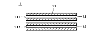
- FIG. 1 is a cross-sectional view of a separation membrane composite according to one embodiment
- FIG. FIG. 4 is a cross-sectional view showing an enlarged part of the separation membrane composite.
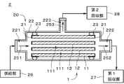
- FIG. 3 shows a separation device;
- FIG. 4 is a diagram showing the flow of separation of mixed gas;
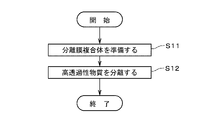
- FIG. 4 is a diagram showing the flow of evaluating the characteristics of a separation membrane module;
- FIG. 1 is a cross-sectional view of a separation membrane composite 1 that is part of a separation membrane module according to one embodiment of the present invention.
- FIG. 2 is a cross-sectional view showing an enlarged part of the separation membrane composite 1.
- a separation membrane composite 1 includes a support 11 and a separation membrane 12 .
- the separation membrane 12 is drawn with a thick line.
- the separation membrane 12 is shaded with diagonal lines, and the thickness of the separation membrane 12 is drawn thicker than it actually is.
- the support 11 is a porous member that is permeable to gas and liquid.
- the support 11 is an integrally formed continuous substantially columnar member.
- the support 11 is provided with a plurality of through holes 111 each extending in the longitudinal direction. That is, the support 11 is a so-called monolithic member.
- the outer shape of the support 11 is, for example, substantially cylindrical.
- a cross section perpendicular to the longitudinal direction of each through-hole 111 (that is, cell) is, for example, substantially circular.
- the diameter of the through-holes 111 is drawn larger than the actual number, and the number of the through-holes 111 is drawn smaller than the actual number.
- the length of the support 11 (that is, the length in the horizontal direction in FIG. 1) is, for example, 10 cm to 200 cm.
- the outer diameter of the support 11 is, for example, 0.5 cm to 30 cm.
- the distance between the central axes of adjacent through holes 111 is, for example, 0.3 mm to 10 mm.
- the surface roughness (Ra) of the support 11 is, for example, 0.1 ⁇ m to 5.0 ⁇ m, preferably 0.2 ⁇ m to 2.0 ⁇ m.
- the shape of the support 11 may be, for example, a honeycomb shape, a flat plate shape, a tubular shape, a cylindrical shape, a columnar shape, a polygonal columnar shape, or the like. When the shape of the support 11 is tubular or cylindrical, the thickness of the support 11 is, for example, 0.1 mm to 10 mm.
- the support 11 is made of a ceramic sintered body.
- Ceramic sintered bodies selected as the material for the support 11 include, for example, alumina, silica, mullite, zirconia, titania, yttria, silicon nitride, and silicon carbide.
- support 11 contains at least one of alumina, silica and mullite.
- the support 11 may contain an inorganic binder. At least one of titania, mullite, sinterable alumina, silica, glass frit, clay mineral, and sinterable cordierite can be used as the inorganic binder.
- the average pore size of the support 11 is, for example, 0.01 ⁇ m to 70 ⁇ m, preferably 0.05 ⁇ m to 25 ⁇ m.
- the average pore size of the support 11 near the surface where the separation membrane 12 is formed is 0.01 ⁇ m to 1 ⁇ m, preferably 0.05 ⁇ m to 0.5 ⁇ m.
- Average pore size can be measured, for example, by a mercury porosimeter, a perm porosimeter or a nanoperm porosimeter.
- D5 is, for example, 0.01 ⁇ m to 50 ⁇ m
- D50 is, for example, 0.05 ⁇ m to 70 ⁇ m
- D95 is, for example, 0.1 ⁇ m to 2000 ⁇ m.
- the porosity of the support 11 near the surface where the separation membrane 12 is formed is, for example, 20% to 60%.
- the support 11 has, for example, a multi-layer structure in which multiple layers with different average pore diameters are laminated in the thickness direction.
- the average pore size and sintered grain size in the surface layer including the surface on which separation membrane 12 is formed are smaller than the average pore size and sintered grain size in layers other than the surface layer.
- the average pore diameter of the surface layer of the support 11 is, for example, 0.01 ⁇ m to 1 ⁇ m, preferably 0.05 ⁇ m to 0.5 ⁇ m.
- the above materials can be used for each layer.
- the materials of the multiple layers forming the multilayer structure may be the same or different.
- the separation membrane 12 is a substantially cylindrical thin film provided on the inner surface of the through-hole 111 of the support 11 over substantially the entire inner surface.
- the separation membrane 12 is a dense porous membrane having fine pores.
- the separation membrane 12 can separate a specific substance from a mixed substance in which a plurality of types of substances are mixed by utilizing the molecular sieve action.
- the separation membrane 12 is, for example, an inorganic membrane, preferably a zeolite membrane.
- the zeolite membrane is at least one in which zeolite is formed in the form of a membrane on the surface of the support 11, and does not include an organic membrane in which zeolite particles are simply dispersed.
- a zeolite membrane can be used as a separation membrane that separates a specific substance from a mixed substance, as described above.
- a zeolite membrane is less permeable to other substances than the specific substance. In other words, the permeation amount of the other substance through the zeolite membrane is smaller than the permeation amount of the specific substance.
- the zeolite membrane may contain two or more types of zeolites with different structures and compositions.
- the thickness of the separation membrane 12 is, for example, 0.05 ⁇ m to 30 ⁇ m, preferably 0.1 ⁇ m to 20 ⁇ m, more preferably 0.5 ⁇ m to 10 ⁇ m. Separation performance is improved by increasing the thickness of the separation membrane 12 . When the separation membrane 12 is thinned, the permeation rate increases.
- the surface roughness (Ra) of the separation membrane 12 is, for example, 5 ⁇ m or less, preferably 2 ⁇ m or less, more preferably 1 ⁇ m or less, and even more preferably 0.5 ⁇ m or less.
- the pore diameter of the zeolite crystals contained in the separation membrane 12 (hereinafter also simply referred to as “the pore diameter of the separation membrane 12”) is 0.2 nm or more and 0.8 nm or less, more preferably 0.3 nm or more and It is 0.7 nm or less, more preferably 0.3 nm or more and 0.45 nm or less.
- the pore diameter of the separation membrane 12 is less than 0.2 nm, the amount of substances permeating through the separation membrane 12 may decrease. may result in insufficient selectivity.
- the pore diameter of the separation membrane 12 is the diameter of the pores in a direction substantially perpendicular to the maximum diameter of the pores of the zeolite crystals constituting the separation membrane 12 (i.e., the longest diameter that is the maximum distance between oxygen atoms) (i.e., short diameter).
- the pore diameter of the separation membrane 12 is smaller than the average pore diameter of the surface of the support 11 on which the separation membrane 12 is arranged.
- the minor diameter of the n-membered ring pores is the pore diameter of the separation membrane 12 .
- the minor diameter of the n-membered ring pore having the largest minor diameter is taken as the pore diameter of the separation membrane 12 .
- the n-membered ring is a portion in which the number of oxygen atoms constituting the pore-forming skeleton is n, and each oxygen atom is bonded to a T atom described later to form a ring structure.
- n-membered ring refers to a ring that forms a through hole (channel), and does not include a ring that does not form a through hole.
- An n-membered ring pore is a pore formed by an n-membered ring.
- the maximum number of ring members of the zeolite contained in the separation membrane 12 is preferably 8 or less (eg, 6 or 8).
- the pore diameter of the separation membrane 12, which is a zeolite membrane, is uniquely determined by the framework structure of the zeolite. iza-structure. It can be obtained from the values disclosed in org/databases/>.
- the type of zeolite that constitutes the separation membrane 12 is not particularly limited. (X-type, Y-type), GIS-type, IHW-type, LEV-type, LTA-type, LTJ-type, MEL-type, MFI-type, MOR-type, PAU-type, RHO-type, SOD-type, and SAT-type zeolite.
- the zeolite is an eight-membered ring zeolite, for example, AEI type, AFN type, AFV type, AFX type, CHA type, DDR type, ERI type, ETL type, GIS type, IHW type, LEV type, LTA type, LTJ type, RHO type, SAT type zeolite, and the like.
- the zeolite forming the separation membrane 12 contains, for example, aluminum (Al) as T atoms (that is, atoms positioned at the center of oxygen tetrahedrons (TO 4 ) forming the zeolite).
- the zeolite constituting the separation membrane 12 includes zeolite in which T atoms are composed of only silicon (Si) or Si and Al, AlPO-type zeolite in which T atoms are composed of Al and phosphorus (P), and zeolite whose T atoms are composed of Si.
- SAPO-type zeolite consisting of and Al and P
- MAPSO-type zeolite consisting of T atoms consisting of magnesium (Mg), Si, Al, and P
- ZnAPSO consisting of T atoms consisting of zinc (Zn), Si, Al, and P type zeolites and the like
- Some of the T atoms may be substituted with other elements.
- the isolation film 12 contains, for example, Si. Separation film 12 may contain any two or more of Si, Al and P, for example. Separation membrane 12 may contain an alkali metal. The alkali metal is, for example, sodium (Na) or potassium (K).
- the Si/Al ratio in the separation film 12 is, for example, 1 or more and 100,000 or less.
- the Si/Al ratio is the molar ratio of Si element to Al element contained in separation film 12 .
- the Si/Al ratio is preferably 5 or more, more preferably 20 or more, still more preferably 100 or more, and the higher the better.
- the Si/Al ratio in the separation film 12 can be adjusted by adjusting the mixing ratio of the Si source and the Al source in the raw material solution, which will be described later.
- the separation membrane 12 may include a membrane other than the zeolite membrane in addition to the zeolite membrane.
- the separation membrane 12 may be a membrane other than a zeolite membrane.
- FIG. 3 is a diagram showing the separation device 2.
- FIG. 4 is a diagram showing the flow of separation of the mixed substance by the separation device 2. As shown in FIG.
- a mixed substance containing multiple types of fluids that is, gas or liquid
- a highly permeable substance in the mixed substance is permeated through the separation membrane composite 1.
- separated from the mixture by Separation in the separation device 2 may be performed, for example, for the purpose of extracting a highly permeable substance (hereinafter also referred to as a "highly permeable substance”) from a mixed substance, and a low-permeable substance (hereinafter also referred to as a " (also referred to as "low-permeability substances”).
- the mixed substance (that is, mixed fluid) may be a mixed gas containing multiple types of gas, a mixed liquid containing multiple types of liquid, or a gas-liquid two-phase mixture containing both gas and liquid. It may be a fluid.
- Mixed substances include, for example, hydrogen (H 2 ), helium (He), nitrogen (N 2 ), oxygen (O 2 ), water (H 2 O), water vapor (H 2 O), carbon monoxide (CO), Carbon dioxide ( CO2 ), Nitrogen oxides, Ammonia ( NH3 ), Sulfur oxides, Hydrogen sulfide ( H2S ), Sulfur fluoride, Mercury (Hg), Arsine (AsH3) , Hydrogen cyanide (HCN), Sulfide Contains one or more of carbonyls (COS), C1-C8 hydrocarbons, organic acids, alcohols, mercaptans, esters, ethers, ketones and aldehydes.
- the above mentioned highly permeable substances are for example one or more of H2, N2 , O2 , H2O , CO2 and H2S .
- Nitrogen oxides are compounds of nitrogen and oxygen. Nitrogen oxides mentioned above include, for example, nitric oxide (NO), nitrogen dioxide (NO 2 ), nitrous oxide (also referred to as dinitrogen monoxide) (N 2 O), dinitrogen trioxide (N 2 O 3 ), dinitrogen tetroxide (N 2 O 4 ), dinitrogen pentoxide (N 2 O 5 ), and other gases called NO x (nox).
- NO nitric oxide
- NO 2 nitrogen dioxide
- NO 2 O nitrous oxide
- N 2 O 3 dinitrogen trioxide
- N 2 O 4 dinitrogen tetroxide
- N 2 O 5 dinitrogen pentoxide
- Sulfur oxides are compounds of sulfur and oxygen.
- the above sulfur oxides are gases called SOx (socks) such as sulfur dioxide (SO 2 ) and sulfur trioxide (SO 3 ).
- Sulfur fluoride is a compound of fluorine and sulfur.
- C1-C8 hydrocarbons are hydrocarbons having 1 or more and 8 or less carbons.
- the C3-C8 hydrocarbons may be straight chain compounds, side chain compounds and cyclic compounds.
- C2 to C8 hydrocarbons include saturated hydrocarbons (that is, those in which double bonds and triple bonds are not present in the molecule), unsaturated hydrocarbons (that is, those in which double bonds and/or triple bonds are present in the molecule). existing within).
- the organic acids mentioned above are carboxylic acids, sulfonic acids, and the like.
- Carboxylic acids are, for example, formic acid (CH 2 O 2 ), acetic acid (C 2 H 4 O 2 ), oxalic acid (C 2 H 2 O 4 ), acrylic acid (C 3 H 4 O 2 ) or benzoic acid (C 6 H 5 COOH) and the like.
- Sulfonic acid is, for example, ethanesulfonic acid (C 2 H 6 O 3 S).
- the organic acid may be a chain compound or a cyclic compound.
- the aforementioned alcohols are, for example, methanol (CH 3 OH), ethanol (C 2 H 5 OH), isopropanol (2-propanol) (CH 3 CH(OH)CH 3 ), ethylene glycol (CH 2 (OH)CH 2 (OH)) or butanol ( C4H9OH ), and the like.
- Mercaptans are organic compounds having hydrogenated sulfur (SH) at the end, and are also called thiols or thioalcohols.
- the mercaptans mentioned above are, for example, methyl mercaptan (CH 3 SH), ethyl mercaptan (C 2 H 5 SH) or 1-propanethiol (C 3 H 7 SH).
- esters are, for example, formate esters or acetate esters.
- ethers are, for example, dimethyl ether ((CH 3 ) 2 O), methyl ethyl ether (C 2 H 5 OCH 3 ) or diethyl ether ((C 2 H 5 ) 2 O).
- ketones mentioned above are, for example, acetone (( CH3 )2CO), methyl ethyl ketone ( C2H5COCH3 ) or diethylketone ( ( C2H5 ) 2CO ).
- aldehydes mentioned above are, for example, acetaldehyde (CH 3 CHO), propionaldehyde (C 2 H 5 CHO) or butanal (butyraldehyde) (C 3 H 7 CHO).
- the mixed substance separated by the separation device 2 is a mixed gas containing multiple types of gases.
- the separation device 2 includes a separation membrane module 20, a supply section 26, a first recovery section 27, and a second recovery section 28.
- the separation membrane module 20 includes a separation membrane composite 1 , a sealing portion 21 , a housing 22 and two sealing portions 23 . Separation membrane composite 1 , sealing portion 21 and sealing portion 23 are accommodated in housing 22 .
- the supply portion 26 , the first recovery portion 27 and the second recovery portion 28 are arranged outside the housing 22 and connected to the housing 22 .
- the sealing portions 21 are attached to both ends of the support 11 in the longitudinal direction (that is, the left-right direction in FIG. 3), and cover both longitudinal end surfaces of the support 11 and outer surfaces in the vicinity of the both end surfaces. It is a member that seals The sealing portion 21 prevents the inflow and outflow of gas and liquid from the both end faces of the support 11 .
- the sealing portion 21 is, for example, a plate-like or film-like member made of glass or resin. The material and shape of the sealing portion 21 may be changed as appropriate. Since the sealing portion 21 is provided with a plurality of openings that overlap with the plurality of through holes 111 of the support 11 , both longitudinal ends of the through holes 111 of the support 11 are covered by the sealing portion 21 . It has not been. Therefore, gas and liquid can flow in and out of the through hole 111 from both ends.
- the shape of the housing 22 is not particularly limited, it is, for example, a substantially cylindrical tubular member.
- the housing 22 is made of stainless steel or carbon steel, for example.
- the longitudinal direction of the housing 22 is substantially parallel to the longitudinal direction of the separation membrane composite 1 .
- a supply port 221 is provided at one longitudinal end of the housing 22 (that is, the left end in FIG. 3), and a first discharge port 222 is provided at the other end.
- a second discharge port 223 is provided on the side surface of the housing 22 .
- the supply portion 26 is connected to the supply port 221 .
- the first recovery section 27 is connected to the first discharge port 222 .
- the second recovery section 28 is connected to the second discharge port 223 .
- the internal space of the housing 22 is a closed space isolated from the surrounding space of the housing 22 .
- the two seal portions 23 are arranged along the entire circumference between the outer surface of the separation membrane composite 1 and the inner surface of the housing 22 near both ends in the longitudinal direction of the separation membrane composite 1 .
- Each seal portion 23 is a substantially annular member made of a material impermeable to gas and liquid.
- the seal portion 23 is, for example, an O-ring made of flexible resin.
- the seal portion 23 is in close contact with the outer surface of the separation membrane composite 1 and the inner surface of the housing 22 over the entire circumference. In the example shown in FIG. 3 , the sealing portion 23 is in close contact with the outer surface of the sealing portion 21 and indirectly in close contact with the outer surface of the separation membrane composite 1 through the sealing portion 21 . Between the seal portion 23 and the outer surface of the separation membrane composite 1 and between the seal portion 23 and the inner surface of the housing 22 are sealed, and little or no passage of gas and liquid is possible. be.
- the supply unit 26 supplies the mixed gas to the internal space of the housing 22 through the supply port 221 .
- the supply unit 26 includes, for example, a pumping mechanism such as a blower or a pump that pumps the mixed gas toward the housing 22 .
- the pumping mechanism includes, for example, a temperature control section and a pressure control section that control the temperature and pressure of the mixed gas supplied to the housing 22, respectively.
- the first recovery unit 27 and the second recovery unit 28 include, for example, a storage container that stores the gas drawn out from the housing 22, or a blower or pump that transfers the gas.
- the separation membrane composite 1 is prepared ( FIG. 4 : step S11). Specifically, the separation membrane composite 1 is attached inside the housing 22 . Subsequently, the supply unit 26 supplies a mixed gas containing a plurality of types of gases having different permeability to the separation membrane 12 into the housing 22 as indicated by an arrow 251 .
- the main components of the mixed gas are CO2 and CH4 .
- the mixed gas may contain gases other than CO2 and CH4 .
- the pressure of the mixed gas supplied from the supply portion 26 to the inside of the housing 22 (that is, the supply side pressure, which is the pressure on the primary side of the separation membrane 12) is, for example, 0.1 MPaG to 20.0 MPaG.
- the temperature of the mixed gas supplied from the supply unit 26 is, for example, 10.degree. C. to 250.degree.
- the mixed gas supplied from the supply part 26 to the housing 22 is introduced into each through-hole 111 of the support 11 from the left end of the separation membrane composite 1 in the figure.
- a highly permeable substance which is a gas with high permeability in the mixed gas, permeates through the separation membrane 12 provided on the inner surface of each through-hole 111 and the support 11 and is led out from the outer surface of the support 11. be done.
- a highly permeable substance eg, CO 2
- a low-permeable substance eg, CH 4
- the gas discharged from the outer surface of the support 11 (hereinafter referred to as "permeable substance") is guided to the second recovery section 28 via the second discharge port 223 as indicated by an arrow 253, Collected by the second collecting unit 28 .
- the pressure of the gas recovered by the second recovery section 28 (that is, the pressure on the secondary side of the separation membrane 12, that is, the pressure on the permeate side) is, for example, 0.0 MPaG.
- the difference between the feed side pressure and the permeate side pressure is, for example, 0.1 MPa to 20.0 MPa.
- the permeable substance may include a low-permeable substance that has permeated the separation membrane 12 in addition to the above-described high-permeable substance.
- gases excluding substances that have permeated the separation membrane 12 and the support 11 pass through the through-holes 111 of the support 11 from the left to the right in the drawing. , and is recovered by first recovery section 27 via first discharge port 222 as indicated by arrow 252 .
- the pressure of the gas recovered by the first recovery section 27 is, for example, substantially the same as the introduction pressure.
- the impermeable substance may include a highly permeable substance that has not permeated through the separation membrane 12 in addition to the low-permeable substance described above.
- the impermeable substance recovered by the first recovery section 27 may be, for example, circulated to the supply section 26 and supplied again into the housing 22 .
- the characteristics of the separation membrane module 20 are the performance of the separation membrane 12 (for example, the permeation amount of a highly permeable substance), the seal portion 23 that seals between the separation membrane composite 1 and the housing 22, and the It is determined by the amount of leakage from defects existing in the separation membrane 12 and the like.
- the amount of leakage refers to defects such as microscopic gaps between the seal portion 23 and the separation membrane composite 1 and/or the housing 22, and defects such as cracks and peeling in the separation membrane 12. It is the amount of mixed gas recovered by the part 28 .
- the mixed gas that has passed through these defects leaks into the space on the secondary side of the separation membrane 12 (that is, the space on the permeate side) without passing through the pores of the separation membrane 12. Not separated.
- the permeated substance that has passed through the pores of the separation membrane 12 (that is, separated by the separation membrane 12) and the mixed gas that has leaked from the defect of the separation membrane module 20 (that is, leaked) Both are recovered.
- FIG. 5 is a diagram showing the flow of evaluating the characteristics of the separation membrane module 20.
- FIG. Evaluation of the characteristics of the separation membrane module 20 is performed using the above-described separation device 2 shown in FIG.
- the performance-deteriorated gas which has the property of reducing the permeation amount of the separation membrane 12
- the performance-degraded gas supplied from the supply unit 26 to the housing 22 is introduced into each through hole 111 of the support 11 (that is, the primary side of the separation membrane 12), and is introduced into the pores of the separation membrane 12 (for example, the separation membrane 12 (near the pore entrance on the primary side) of (step S21).
- the performance-deteriorating gas partially or wholly blocks the pores of the separation membrane 12 by being adsorbed thereon. This prevents the later-described evaluation fluid or the like from passing through the pores of the separation membrane 12 .
- the performance-degraded gas is supplied to the primary side of the separation membrane 12 for a predetermined period of time.
- the performance-degraded gas may be a gas composed of one kind of substance, or a mixed gas containing two or more kinds of substances.
- the degraded gas includes, for example, at least one of water and organic matter.
- the degraded gas may be, for example, N2 gas containing less than the saturated amount of water vapor (ie, unsaturated water vapor), or air containing unsaturated water vapor.
- the performance-deteriorating gas may be air containing vapors of volatile organic compounds (hereinafter also referred to as “unsaturated VOCs (Volatile Organic Compounds)”) less than the amount of saturated vapors.
- the degraded gas may be a gas mixture containing CH4 and alcohol vapor.
- the performance-degrading gas preferably contains a component having a boiling point of ⁇ 10° C. or higher under atmospheric pressure. Thereby, the pores of the separation membrane 12 can be efficiently blocked.
- the performance-degrading gas preferably has a total concentration of 0.05 mol % or more of components having a boiling point of ⁇ 10° C. or higher under atmospheric pressure. Thereby, the pores of the separation membrane 12 can be blocked more efficiently.
- the upper limit of the total concentration of components with a boiling point of ⁇ 10° C. or higher under atmospheric pressure contained in the performance-degraded gas is not particularly limited as long as it is unsaturated, but considering the ease of regeneration treatment of the separation membrane 12 described later. Then, it is usually preferably 90 mol % or less.
- gas containing droplets is not used as the performance-degraded gas. If the gas containing droplets is used as the performance-degraded gas, it will take a long time to remove the liquid adsorbed in the pores of the separation membrane 12 in the regeneration treatment of the separation membrane 12, which will be described later, and the treatment cost will increase. , the separation performance of the separation membrane 12 after the regeneration treatment may deteriorate. Further, in the evaluation of the characteristics of the separation membrane module 20, which will be described later, the liquid may temporarily clog defects in the seal portion 23 and the separation membrane 12, resulting in deterioration in evaluation accuracy. For the same reason, liquids and gases containing saturated vapor are also not used as the degraded gas.
- step S22 the permeation amount reduction rate of the separation membrane 12 due to the performance-deteriorating gas is confirmed (step S22).
- a permeation amount measuring fluid for measuring the permeation amount decrease rate of the separation membrane 12 is supplied to the interior of the housing 22 by the supply unit 26, and is supplied into each through hole 111 of the support 11 (that is, separation (primary side of membrane 12). Part of the permeation amount measurement fluid permeates the separation membrane 12 and the support 11 and is recovered by the second recovery section 28 .
- the recovery amount of the permeation amount measurement fluid recovered by the second recovery unit 28 (that is, the amount of the permeation amount measurement fluid that has moved to the secondary side of the separation membrane 12) is increased to that in step S22 before step S21.
- a similar measurement is performed and compared with the collected amount of the permeation amount measurement fluid obtained in advance (that is, the collected amount before performance deterioration due to the performance deterioration gas), and the permeation amount decrease rate before and after step S22 is confirmed.
- the permeation amount reduction rate is obtained by dividing the recovered amount of the permeation amount measurement fluid after performance deterioration due to the performance deterioration gas by the recovery amount of the permeation amount measurement fluid before the performance deterioration, and subtracting the value obtained by dividing from 1. required by The permeation amount decrease rate is, for example, 30% or more, preferably 50% or more, and more preferably 60% or more.
- the permeation amount measurement fluid may be a fluid composed of one kind of substance, or a mixed fluid containing two or more kinds of substances.
- the permeation amount measurement fluid may be a gas, a liquid, or a gas-liquid two-phase fluid.
- the permeation amount measurement fluid is, for example, an inorganic gas such as N 2 gas or CO 2 gas.
- the permeation amount measurement fluid may contain at least one of water and organic matter as well as the degraded gas.
- the permeation amount measurement fluid may be liquid water.
- the permeation amount measurement fluid may be N2 gas containing saturated water vapor, or air containing saturated water vapor.
- the permeation measurement fluid may be a mixed gas containing CH4 and water vapor.
- the permeation amount measurement fluid may be a gas-liquid two-phase fluid containing CO 2 gas or air and droplets of HC, or a mixed gas containing CO 2 gas and alcohol vapor.
- the permeation amount measurement fluid may be a gas having the same components as the performance-deteriorating gas.
- step S22 the evaluation fluid for evaluating the characteristics of the separation membrane module 20 is supplied by the supply unit 26 to the inside of the housing 22, and is injected into each through-hole 111 of the support 11 (that is, the separation membrane 12). primary side). Part of the evaluation fluid permeates the separation membrane 12 and the support 11 and is recovered by the second recovery section 28 . Another portion of the evaluation fluid passes through defects in the seal portion 23 and the separation membrane 12 and is recovered by the second recovery portion 28 . Then, the recovery amount of the evaluation fluid recovered by the second recovery unit 28 (that is, the flow rate of the evaluation fluid to the secondary side of the separation membrane 12) is measured (step S23).
- the evaluation differential pressure which is the difference between the supply-side pressure and the permeate-side pressure in step S23, is, for example, 0.1 MPa or more.
- the differential pressure at evaluation is preferably 0.5 MPa or more, more preferably 1.0 MPa or more.
- the permeation of the evaluation fluid is inhibited by the performance-deteriorating gas. Therefore, in the evaluation fluid recovered by the second recovery unit 28, the evaluation fluid that has passed through the defect occupies the The percentage increases compared to when there is no reduction in permeation due to the degraded gas. As a result, the difference in the recovery amount of the evaluation fluid due to the presence or absence of the defect becomes significant.
- the evaluation fluid may be a fluid composed of one kind of substance, or a mixed fluid containing two or more kinds of substances.
- the evaluation fluid may be a gas, a liquid, or a gas-liquid two-phase fluid.
- the evaluation fluid is, for example, an inorganic gas such as N2 gas or CO2 gas.
- the evaluation fluid may contain a degrading gas.
- the molecular diameter of the evaluation fluid is, for example, greater than or equal to the molecular diameter of the permeation amount measurement fluid.
- the molecular diameter of the evaluation fluid refers to the remaining substances (hereinafter also referred to as "molecular diameter evaluation substances") after excluding substances with a content of 10% by volume or less from the substances contained in the evaluation fluid. Among them, it means the molecular diameter of the substance with the smallest molecular diameter.
- the substance for molecular diameter evaluation is the remaining substance from the substances contained in the fluid for evaluation, excluding the substances with a content rate of 10% by volume or less and the liquid substances. is.
- the evaluation fluid is a mixed fluid containing 2% by volume of water vapor and 98% by volume of air
- O2 and N2 in the air except for water vapor, whose content is 10% by volume or less, have a molecular diameter of It becomes an evaluation substance.
- O 2 (molecular diameter 0.35 nm) and N 2 (molecular diameter 0.36 nm) the molecular diameter 0.35 nm of O 2 having the smaller molecular diameter is taken as the molecular diameter of the evaluation fluid.
- the molecular diameter of O2 which has the smaller molecular diameter among O2 and N2 in the air, is 0.35 nm is taken as the molecular diameter of the evaluation fluid.
- the molecular diameter of the permeation amount measurement fluid is the same as that of the evaluation fluid.
- the molecular diameter of the evaluation fluid is, for example, 0.40 nm or less.
- the content of fluids with a molecular diameter of 0.40 nm or less in all substances for molecular diameter evaluation is preferably 80% by volume or more. .
- the molecular diameter of the evaluation fluid is, for example, 1.06 times or less the pore diameter of the separation membrane 12 .
- the evaluation fluid passes through the defect to perform the second recovery. Since it is collected by the unit 28, it becomes easier to determine the presence or absence of the defect.
- the fluid for evaluation is a mixed fluid containing a plurality of types of substances for molecular diameter evaluation
- the content of the fluid whose molecular diameter is 1.06 times or less the pore diameter of the separation membrane 12 in all the substances for molecular diameter evaluation is 70. % by volume or more.
- the pore diameter of the separation membrane 12 means the average pore diameter of the separation membrane 12 .
- the recovery amount of the evaluation fluid measured in step S23 (hereinafter also referred to as "measured recovery amount") is compared with the reference recovery amount, thereby evaluating the characteristics of the separation membrane module 20 (step S24).
- the reference recovery amount can be arbitrarily set according to the performance of the separation membrane 12, the specifications required for the separation membrane module 20, and the like.
- the reference recovery amount can be set as a value obtained by multiplying the permissible leakage amount of the evaluation fluid (that is, the leakage amount of the evaluation fluid that does not pass through the pores of the separation membrane 12) by a constant coefficient.
- step S24 if the measured recovery amount of the evaluation fluid is equal to or less than the reference recovery amount, the leakage amount of the evaluation fluid from the defect of the separation membrane module 20 (that is, the evaluation fluid that does not pass through the pores of the separation membrane 12 ) is small, and the separation membrane module 20 is judged to be in good condition.
- the measured recovery amount of the evaluation fluid is larger than the reference recovery amount, the leakage amount of the evaluation fluid in the separation membrane module 20 is large, and the separation membrane module 20 is judged to be in a defective state.
- the separation membrane module 20 is determined to be in a defective state, for example, the separation membrane module 20 is repaired (that is, replacement of the seal portion 23, repair of cracks in the separation membrane 12, etc.).
- the separation membrane 12 is regenerated to restore the permeation amount of the separation membrane 12 that has decreased due to the performance-deteriorated gas (step S25).
- the separation membrane composite 1 is heated to remove the performance-deteriorating gas adsorbed in the pores of the separation membrane 12 .
- the performance-deteriorated gas is a gas that does not substantially contain steam or a gas that contains unsaturated steam (that is, less than the saturated amount of steam). Gas can be easily removed.
- the separation membrane composite 1 is heated by, for example, supplying high-temperature dry air from the supply section 26 into the housing 22 .
- the moisture content of the dry air is, for example, 300 ppm or less.
- steps S21 to S25 may be performed during a process such as separation of the mixed gas by the separation membrane module 20. This makes it possible to detect deterioration of the characteristics of the separation membrane module 20 due to aging.
- step S22 it is not always necessary to supply the permeation amount measurement fluid to the separation membrane 12 and measure the amount recovered by the second recovery unit 28 after step S21, as long as the permeation amount decrease rate can be confirmed.
- the performance-degraded gas used in step S21 The permeation amount decrease rate in step S22 may be confirmed by extracting the corresponding permeation amount decrease rate from the information (hereinafter also referred to as "performance deterioration gas-decrease rate information").
- the performance-deteriorated gas-deterioration rate information includes a plurality of permeation amount decrease rates corresponding to the case where the supply time to the separation membrane 12 is changed or the content rate of the component is changed for each performance-deteriorated gas. may be
- Examples 1 to 7 the type of performance-deteriorated gas supplied to the separation membrane 12 in step S21, the rate of decrease in permeation amount due to the performance-deteriorated gas, the type of evaluation fluid supplied to the separation membrane 12 in step S23, and The evaluation time differential pressure, which is the difference between the supply-side pressure and the permeate-side pressure in step S23, is changed.
- the total concentration of components having a boiling point of ⁇ 10° C. or higher at atmospheric pressure contained in the performance-degrading gas was 0.05 mol % to 90 mol %.
- Comparative Example 1 the supply of the performance-degrading gas in step S21 is omitted.
- step S21 in step S21, a liquid organic solvent was supplied in place of the performance-degrading gas.
- the separation membrane module 20 which is known to be in good condition (that is, the amount of leakage from defects is small), is subjected to steps S21 to S21 described above. S24 was performed. Then, in the "evaluation" column, how well the measurement conditions such as the type of the performance-deteriorating gas, the rate of decrease in the amount of permeation, the type of the fluid for evaluation, and the differential pressure at the time of evaluation are suitable for evaluating the characteristics of the separation membrane module 20. evaluated.
- the separation membrane 12 is a DDR type zeolite membrane.
- the zeolite constituting the separation membrane 12 has an intrinsic pore diameter of 0.36 nm ⁇ 0.44 nm, and the pore diameter of the separation membrane 12 (that is, the short diameter of the zeolite) is 0.36 nm.
- the separation membrane composite 1 was produced as follows. First, the support 11 was immersed in a solution in which seed crystals were dispersed to adhere the seed crystals to the support 11 .
- the seed crystal is powder of DDR type zeolite produced by hydrothermal synthesis, or pulverized powder. Note that the seed crystal may be attached to the support 11 by a method other than the above. Subsequently, hydrothermal synthesis was performed by immersing the support 11 to which the seed crystals were attached in the raw material solution. As a result, DDR-type zeolite was grown using the seed crystals as nuclei, and a separation 12 that was a DDR-type zeolite membrane was formed on the support 11 .
- a raw material solution was prepared by dissolving a Si source, a structure-directing agent (hereinafter also referred to as "SDA"), and the like in a solvent.
- the composition of the raw material solution is 1.0SiO2:0.015SDA:0.12( CH2 ) 2 ( NH2 ) 2 .
- the solvent of the raw material solution is water, and the SDA contained in the raw material solution is 1-adamantanamine.
- the temperature during hydrothermal synthesis is preferably 120 to 200°C, for example 160°C.
- the hydrothermal synthesis time is preferably 10 to 100 hours, for example 30 hours. After completion of the hydrothermal synthesis, the support and the separation membrane 12 were washed and heat-treated to burn off the SDA in the separation membrane 12 and penetrate the micropores to obtain the separation membrane composite 1 described above.
- Example 1 air containing unsaturated VOCs (that is, VOC vapor less than the saturated vapor amount) was used as the performance-degrading gas in step S21. Isobutane and vinyl acetate were used as VOCs. In step S22, CO 2 gas was used as the fluid for measuring the permeation amount, and the pressure on the supply side and the pressure on the permeation side were set to 0.1 MPaG and atmospheric pressure, respectively, and the permeation amount decrease rate was determined at room temperature. The permeation amount decrease rate was 80%.
- Air was used as the evaluation fluid in step S23, and the differential pressure at evaluation, which is the difference between the supply-side pressure and the permeation-side pressure, was set to 1.0 MPa, and the measured recovery amount of the evaluation fluid was determined.
- the evaluation of the measurement conditions of Example 1 was "A".
- the " ⁇ ” mark in the evaluation column in Table 1 indicates that the measured recovery amount is 40% or less of the standard recovery amount, and that the measurement conditions are very suitable for evaluating the characteristics of the separation membrane module 20.
- the " ⁇ ” mark in the evaluation column indicates that the measured recovery amount is greater than 40% of the reference recovery amount and is 50% or less, and that the measurement conditions are suitable for the characteristic evaluation of the separation membrane module 20. show.
- the " ⁇ ” mark in the evaluation column indicates that the measured recovery amount is greater than 50% of the standard recovery amount and less than 100%, and although it is not as large as the " ⁇ " mark and the " ⁇ ” mark, the measurement conditions are separated. It is shown to be somewhat suitable for characterization of the membrane module 20.
- the "x" mark indicates that the measured recovery amount is 100% or more of the reference recovery amount, and the flow rate of the evaluation fluid that permeates the separation membrane 12 is large, so the separation membrane module 20 cannot be characterized. In addition, even if the regeneration of the separation membrane 12 in step S25 does not sufficiently recover the permeation amount of the separation membrane 12, it is included in the "x" mark.
- Example 2 is similar to Example 1, except that CO2 gas containing unsaturated VOCs was used as the degraded gas and evaluation fluid.
- the permeation amount reduction rate of Example 2 was 80%.
- the evaluation of Example 2 is “ ⁇ ”, and the measurement conditions are very suitable for characterization of the separation membrane module 20 .
- Example 3 is the same as Example 2 except that the differential pressure at the time of evaluation was set to 0.5 MPa.
- the permeation amount reduction rate of Example 3 was 80%.
- the evaluation of Example 3 is “ ⁇ ”, and the measurement conditions are suitable for characterization of the separation membrane module 20 .
- Example 4 is the same as Example 2 except that the differential pressure at the time of evaluation was set to 0.1 MPa.
- the permeation amount reduction rate of Example 4 was 80%.
- the evaluation of Example 4 is “ ⁇ ”, and the measurement conditions are suitable for characterization of the separation membrane module 20 to some extent.
- Example 5 is the same as Example 1, except that N 2 gas containing unsaturated water vapor is used as the performance-degrading gas and the evaluation fluid, and the pressure difference at the time of evaluation is 4.0 MPa.
- the permeation amount reduction rate of Example 5 was 30%.
- the evaluation of Example 5 is “ ⁇ ”, and the measurement conditions are suitable for characterization of the separation membrane module 20 to some extent.
- Example 6 was similar to Example 5, except that the water vapor content of the degraded gas was changed (specifically, the water vapor content was increased over Example 5 within the range of unsaturation). be.
- the permeation amount reduction rate of Example 6 was 50%.
- the evaluation of Example 6 is “ ⁇ ”, and the measurement conditions are suitable for characterization of the separation membrane module 20 .
- Example 7 is similar to Example 1 , except that CH4 gas containing less than saturated alcohol vapor (specifically, ethanol vapor) was used as the degraded gas and evaluation fluid.
- the permeation amount reduction rate of Example 7 was 70%.
- the evaluation of Example 7 is “A”, and the measurement conditions are very suitable for characterization of the separation membrane module 20 .
- Comparative Example 1 As described above, the performance-degrading gas was not supplied to the separation membrane 12, so the permeation amount decrease rate was 0%. N2 gas was used as the evaluation fluid, and the recovery amount of the evaluation fluid was measured for the same separation membrane module 20 as in Example 1 (that is, the separation membrane module 20 in good condition). Due to the high flow rate of the fluid, the condition of the separation membrane module 20 could not be determined to be good. That is, the evaluation of Comparative Example 1 was "x".
- Comparative Example 2 is the same as Comparative Example 1 except that a liquid organic solvent is supplied to the separation membrane 12 instead of the performance-deteriorating gas.
- the permeation amount decrease rate was 95%.
- the permeation amount of the separation membrane 12 was not sufficiently recovered even by the regeneration of the separation membrane 12 in step S25, so the evaluation of Comparative Example 2 was "x".
- the evaluation of the measurement conditions is improved by increasing the differential pressure at the time of evaluation.
- the differential pressure at the time of evaluation is more preferably 0.5 MPa or more, further preferably 1.0 MPa or more.
- the permeation amount decrease rate is more preferably 50% or more, further preferably 70% or more.
- the evaluation method of the separation membrane module 20 includes the step of supplying the performance-degraded gas having the property of reducing the permeation amount of the separation membrane 12 to the primary side of the separation membrane 12 (step S21); After that, a step of supplying the evaluation fluid to the primary side of the separation membrane 12 and measuring the flow rate to the secondary side of the separation membrane 12 (step S23).
- step S23 the flow rate of the evaluation fluid that permeates the separation membrane 12 (that is, passes through the pores of the separation membrane 12) is reduced. Therefore, in the evaluation fluid recovered by the second recovery unit 28, the ratio of the evaluation fluid that has passed through the defects in the seal portion 23, the separation membrane 12, and the like increases. As a result, the difference in the recovery amount of the evaluation fluid due to the presence or absence of the defect becomes significant, so the characteristics of the separation membrane module 20 can be evaluated with high accuracy.
- the evaluation fluid since the evaluation fluid is suppressed from permeating the separation membrane 12 due to the performance-degraded gas, the evaluation fluid does not necessarily permeate the separation membrane 12 with a molecular diameter larger than the pore diameter of the separation membrane 12. No fluids need to be used. In other words, compared to the case where the type of evaluation fluid is limited by the molecular diameter, the degree of freedom in selecting the evaluation fluid can be improved. As a result, compared with the case where the above-mentioned Fluorinert or the like has to be used as the evaluation fluid, the evaluation fluid can be released and recovered easily.
- the permeation amount decrease rate of the separation membrane 12 before and after step S21 is preferably 30% or more.
- the flow rate of the evaluation fluid that permeates the separation membrane 12 in step S23 can be suitably reduced.
- the difference in the recovery amount of the evaluation fluid due to the presence or absence of the defect is suitably made conspicuous, so that the characteristic evaluation of the separation membrane module 20 can be performed with higher accuracy.
- the molecular diameter of the evaluation fluid is preferably 0.40 nm or less. As a result, even if there is a relatively small defect (for example, a defect with a diameter of about 0.40 nm) in the seal portion 23 or the separation membrane 12, the evaluation fluid passes through the defect and passes through the second recovery portion. 28. Therefore, the characteristic evaluation of the separation membrane module 20 can be performed with higher accuracy.
- the molecular diameter of the evaluation fluid is preferably 1.06 times or less the pore diameter of the separation membrane 12.
- the separation membrane 12 is preferably an inorganic membrane. Thereby, the heat resistance and/or organic solvent resistance of the separation membrane module 20 can be improved.
- the separation membrane 12 is a zeolite membrane.
- the separation membrane 12 is a zeolite membrane.
- the maximum number of ring members of the zeolite constituting the separation membrane 12 is 8 or less.
- the evaluation fluid has the same components as the performance-deteriorating gas.
- the performance-deteriorating gas adsorbed in the pores of the separation membrane 12 in step S21 can be prevented from desorbing from the pores due to the supply of the evaluation fluid in step S23.
- the characteristic evaluation of the separation membrane module 20 can be simplified as compared with the case where the constituent components of the performance-degraded gas and the evaluation fluid are different from each other.
- the performance-deteriorating gas preferably contains at least one of water and organic matter.
- the permeation amount of the separation membrane 12 can be suitably reduced (that is, the permeation amount decrease rate can be increased).
- the separation membrane 12 is regenerated in step S25, the performance-degraded gas can be easily removed from the separation membrane 12.
- the difference between the pressure on the primary side and the pressure on the secondary side of the separation membrane 12 in step S23 is preferably 0.1 MPa or more.
- the differential pressure at the time of evaluation is more preferably 0.5 MPa or more, and even more preferably 1.0 MPa or more.
- the method for evaluating the separation membrane module 20 further includes, after step S23, the step of recovering the permeation amount of the separation membrane 12 that has decreased due to the performance-deteriorating gas and regenerating the separation membrane 12 (step S25). is preferred.
- the separation membrane module 20 after characteristic evaluation can be suitably used for separation of mixed substances and the like.
- the performance-degrading gas preferably contains a total of 0.05 mol% or more of components having a boiling point of -10°C or higher under atmospheric pressure. Thereby, the pores of the separation membrane 12 can be efficiently blocked.
- the performance-degraded gas used in step S21 does not necessarily contain water or organic matter, and a performance-degraded gas that does not contain both water and organic matter may be used in step S21.
- the permeation amount decrease rate of the separation membrane 12 before and after step S21 may be less than 30%.
- the components of the evaluation fluid used in step S23 may be different from or the same as the performance-degraded gas.
- the constituent components of the permeation amount measurement fluid used in step S22 may be different from or the same as those of the performance-degraded gas.
- the molecular diameter of the evaluation fluid may be larger than 1.06 times the pore diameter of the separation membrane 12. Moreover, the molecular diameter of the evaluation fluid may be larger than 0.40 nm. Furthermore, the molecular diameter of the evaluation fluid may be smaller than the molecular diameter of the permeation amount measurement fluid.
- the differential pressure at the time of evaluation in step S23 may be less than 0.1 MPa.
- step S25 may not necessarily be performed after steps S21 to S24 are completed.
- the separation membrane composite 1 may further include a functional membrane or a protective membrane laminated on the separation membrane 12 in addition to the support 11 and the separation membrane 12 .
- Such functional films and protective films may be inorganic films such as zeolite films, silica films or carbon films, or may be organic films such as polyimide films or silicone films.
- the maximum number of ring members of the zeolite that constitutes the separation membrane 12 may be greater than eight.
- the separation membrane 12 may be an inorganic membrane other than the zeolite membrane, or may be an organic membrane.
- the separation device 2 substances other than the substances exemplified in the above description may be separated from the mixed gas. Also, the structure of the separation device 2 is not limited to the above example, and may be modified in various ways.
- the present invention can be used, for example, to evaluate separation membrane modules used for separation and adsorption of various fluids.
Landscapes
- Chemical & Material Sciences (AREA)
- Chemical Kinetics & Catalysis (AREA)
- Life Sciences & Earth Sciences (AREA)
- Geology (AREA)
- Inorganic Chemistry (AREA)
- Separation Using Semi-Permeable Membranes (AREA)
Abstract
Description
[関連出願の参照]
本願は、2021年3月30日に出願された日本国特許出願JP2021-056936からの優先権の利益を主張し、当該出願の全ての開示は、本願に組み込まれる。 TECHNICAL FIELD The present invention relates to a method for evaluating a separation membrane module.
[Reference to related application]
This application claims the benefit of priority from Japanese Patent Application JP2021-056936 filed on March 30, 2021, the entire disclosure of which is incorporated herein.

20 分離膜モジュール
S11~S12,S21~S25 ステップ 12
Claims (12)
- 分離膜モジュールの評価方法であって、
a)分離膜の透過量を低下させる性質を有する性能低下ガスを前記分離膜の一次側に供給する工程と、
b)前記a)工程よりも後に、評価用流体を前記分離膜の一次側に供給し、前記分離膜の二次側への流量を測定する工程と、
を備える。 A method for evaluating a separation membrane module,
a) supplying to the primary side of the separation membrane a performance-deteriorating gas having a property of reducing the permeation amount of the separation membrane;
b) after step a), supplying an evaluation fluid to the primary side of the separation membrane and measuring the flow rate to the secondary side of the separation membrane;
Prepare. - 請求項1に記載の分離膜モジュールの評価方法であって、
前記a)工程の前後における前記分離膜の透過量低下率は30%以上であることを特徴とする。 The method for evaluating the separation membrane module according to claim 1,
The permeation amount decrease rate of the separation membrane before and after the step a) is 30% or more. - 請求項1または2に記載の分離膜モジュールの評価方法であって、
前記評価用流体の分子径は0.40nm以下であることを特徴とする。 The method for evaluating the separation membrane module according to claim 1 or 2,
The evaluation fluid has a molecular diameter of 0.40 nm or less. - 請求項1ないし3のいずれか1つに記載の分離膜モジュールの評価方法であって、
前記評価用流体の分子径は、前記分離膜の細孔径の1.06倍以下であることを特徴とする。 A method for evaluating a separation membrane module according to any one of claims 1 to 3,
The molecular diameter of the evaluation fluid is 1.06 times or less the pore diameter of the separation membrane. - 請求項1ないし4のいずれか1つに記載の分離膜モジュールの評価方法であって、
前記分離膜は無機膜であることを特徴とする。 A method for evaluating a separation membrane module according to any one of claims 1 to 4,
The separation membrane is characterized by being an inorganic membrane. - 請求項5に記載の分離膜モジュールの評価方法であって、
前記分離膜はゼオライト膜であることを特徴とする。 The method for evaluating the separation membrane module according to claim 5,
The separation membrane is a zeolite membrane. - 請求項6に記載の分離膜モジュールの評価方法であって、
前記分離膜を構成するゼオライトの最大員環数は8以下であることを特徴とする。 The method for evaluating the separation membrane module according to claim 6,
The zeolite constituting the separation membrane has a maximum number of ring members of 8 or less. - 請求項1ないし7のいずれか1つに記載の分離膜モジュールの評価方法であって、
前記評価用流体は前記性能低下ガスと構成成分が同一であることを特徴とする。 A method for evaluating a separation membrane module according to any one of claims 1 to 7,
The evaluation fluid is characterized by having the same components as the performance-deteriorating gas. - 請求項1ないし8のいずれか1つに記載の分離膜モジュールの評価方法であって、
前記性能低下ガスは、水および有機物のうち少なくとも一方を含むことを特徴とする。 A method for evaluating a separation membrane module according to any one of claims 1 to 8,
The performance-degrading gas contains at least one of water and organic matter. - 請求項1ないし9のいずれか1つに記載の分離膜モジュールの評価方法であって、
前記b)工程における前記分離膜の一次側の圧力と二次側の圧力との差は0.1MPa以上であることを特徴とする。 A method for evaluating a separation membrane module according to any one of claims 1 to 9,
The difference between the pressure on the primary side and the pressure on the secondary side of the separation membrane in the step b) is 0.1 MPa or more. - 請求項1ないし10のいずれか1つに記載の分離膜モジュールの評価方法であって、
前記b)工程よりも後に、前記性能低下ガスにより低下した前記分離膜の透過量を回復させて前記分離膜を再生させる工程をさらに備えることを特徴とする。 A method for evaluating a separation membrane module according to any one of claims 1 to 10,
It is characterized by further comprising, after the step b), the step of recovering the permeation amount of the separation membrane, which has been reduced by the performance-deteriorating gas, to regenerate the separation membrane. - 請求項1ないし11のいずれか1つに記載の分離膜モジュールの評価方法であって、
前記性能低下ガスは、大気圧下での沸点が-10℃以上である成分を合計0.05mol%以上含むことを特徴とする。 A method for evaluating a separation membrane module according to any one of claims 1 to 11,
The performance-degrading gas is characterized by containing a total of 0.05 mol % or more of components having a boiling point of −10° C. or higher under atmospheric pressure.
Priority Applications (3)
| Application Number | Priority Date | Filing Date | Title |
|---|---|---|---|
| BR112023019506A BR112023019506A2 (en) | 2021-03-30 | 2021-11-17 | SEPARATION MEMBRANE MODULE EVALUATION METHOD |
| JP2023510212A JP7592846B2 (en) | 2021-03-30 | 2021-11-17 | Separation membrane module evaluation method |
| US18/466,113 US20230415099A1 (en) | 2021-03-30 | 2023-09-13 | Method of evaluating separation membrane module |
Applications Claiming Priority (2)
| Application Number | Priority Date | Filing Date | Title |
|---|---|---|---|
| JP2021-056936 | 2021-03-30 | ||
| JP2021056936 | 2021-03-30 |
Related Child Applications (1)
| Application Number | Title | Priority Date | Filing Date |
|---|---|---|---|
| US18/466,113 Continuation US20230415099A1 (en) | 2021-03-30 | 2023-09-13 | Method of evaluating separation membrane module |
Publications (1)
| Publication Number | Publication Date |
|---|---|
| WO2022208980A1 true WO2022208980A1 (en) | 2022-10-06 |
Family
ID=83458513
Family Applications (1)
| Application Number | Title | Priority Date | Filing Date |
|---|---|---|---|
| PCT/JP2021/042192 WO2022208980A1 (en) | 2021-03-30 | 2021-11-17 | Method for evaluating separation membrane module |
Country Status (4)
| Country | Link |
|---|---|
| US (1) | US20230415099A1 (en) |
| JP (1) | JP7592846B2 (en) |
| BR (1) | BR112023019506A2 (en) |
| WO (1) | WO2022208980A1 (en) |
Citations (4)
| Publication number | Priority date | Publication date | Assignee | Title |
|---|---|---|---|---|
| JP2015186776A (en) * | 2014-03-26 | 2015-10-29 | 三菱化学株式会社 | Zeolite membrane evaluation method |
| WO2018180095A1 (en) * | 2017-03-30 | 2018-10-04 | 日本碍子株式会社 | Method for inspecting separation membrane module and method for manufacturing separation membrane module |
| WO2018179959A1 (en) * | 2017-03-30 | 2018-10-04 | 日本碍子株式会社 | Test method for separation membrane structure, manufacturing method for separation membrane module, and manufacturing method for separation membrane structure |
| JP2021023898A (en) * | 2019-08-07 | 2021-02-22 | 三菱ケミカル株式会社 | Leak inspection method for separation membrane module |
-
2021
- 2021-11-17 JP JP2023510212A patent/JP7592846B2/en active Active
- 2021-11-17 WO PCT/JP2021/042192 patent/WO2022208980A1/en active Application Filing
- 2021-11-17 BR BR112023019506A patent/BR112023019506A2/en unknown
-
2023
- 2023-09-13 US US18/466,113 patent/US20230415099A1/en active Pending
Patent Citations (4)
| Publication number | Priority date | Publication date | Assignee | Title |
|---|---|---|---|---|
| JP2015186776A (en) * | 2014-03-26 | 2015-10-29 | 三菱化学株式会社 | Zeolite membrane evaluation method |
| WO2018180095A1 (en) * | 2017-03-30 | 2018-10-04 | 日本碍子株式会社 | Method for inspecting separation membrane module and method for manufacturing separation membrane module |
| WO2018179959A1 (en) * | 2017-03-30 | 2018-10-04 | 日本碍子株式会社 | Test method for separation membrane structure, manufacturing method for separation membrane module, and manufacturing method for separation membrane structure |
| JP2021023898A (en) * | 2019-08-07 | 2021-02-22 | 三菱ケミカル株式会社 | Leak inspection method for separation membrane module |
Also Published As
| Publication number | Publication date |
|---|---|
| JPWO2022208980A1 (en) | 2022-10-06 |
| US20230415099A1 (en) | 2023-12-28 |
| BR112023019506A2 (en) | 2023-10-31 |
| JP7592846B2 (en) | 2024-12-02 |
Similar Documents
| Publication | Publication Date | Title |
|---|---|---|
| JP7257411B2 (en) | Gas separation method and gas separation device | |
| JP7174146B2 (en) | Zeolite membrane composite, method for producing zeolite membrane composite, method for treating zeolite membrane composite, and method for separation | |
| JP7220087B2 (en) | Zeolite membrane composite, method for producing zeolite membrane composite, and separation method | |
| JP2019150823A (en) | Zeolite membrane composite, and manufacturing method of the zeolite membrane composite | |
| US11498035B2 (en) | Zeolite membrane complex, method for producing zeolite membrane complex, and separation method | |
| US20230018523A1 (en) | Gas separation method and zeolite membrane | |
| JP7230176B2 (en) | Zeolite membrane composite, method for producing zeolite membrane composite, and separation method | |
| WO2022208980A1 (en) | Method for evaluating separation membrane module | |
| JP6979548B2 (en) | Zeolite Membrane Complex Manufacturing Method and Zeolite Membrane Complex | |
| JP7590869B2 (en) | Support, zeolite membrane composite, method for producing zeolite membrane composite, and separation method | |
| WO2022163690A1 (en) | Method for heat-treating film | |
| WO2023037886A1 (en) | Method for processing separation membrane composite, and processing apparatus for separation membrane composite | |
| JP7313544B2 (en) | Gas separation method and zeolite membrane | |
| WO2022255055A1 (en) | Mixed gas separation method and mixed gas separation device | |
| WO2023085372A1 (en) | Zeolite membrane composite and membrane reactor | |
| WO2023153172A1 (en) | Separation membrane composite, mixed gas separation apparatus, and method for producing separation membrane composite | |
| WO2023238557A1 (en) | Method for operating separation device and separation device | |
| WO2023162854A1 (en) | Zeolite membrane composite body, method for producing zeolite membrane composite body, and separation method | |
| WO2023162525A1 (en) | Zeolite membrane composite and separation method |
Legal Events
| Date | Code | Title | Description |
|---|---|---|---|
| 121 | Ep: the epo has been informed by wipo that ep was designated in this application |
Ref document number: 21935134 Country of ref document: EP Kind code of ref document: A1 |
|
| WWE | Wipo information: entry into national phase |
Ref document number: 2023510212 Country of ref document: JP |
|
| REG | Reference to national code |
Ref country code: BR Ref legal event code: B01A Ref document number: 112023019506 Country of ref document: BR |
|
| ENP | Entry into the national phase |
Ref document number: 112023019506 Country of ref document: BR Kind code of ref document: A2 Effective date: 20230922 |
|
| NENP | Non-entry into the national phase |
Ref country code: DE |
|
| 122 | Ep: pct application non-entry in european phase |
Ref document number: 21935134 Country of ref document: EP Kind code of ref document: A1 |