WO2022208843A1 - 学習データ処理装置、学習データ処理方法及び学習データ処理プログラム - Google Patents
学習データ処理装置、学習データ処理方法及び学習データ処理プログラム Download PDFInfo
- Publication number
- WO2022208843A1 WO2022208843A1 PCT/JP2021/014159 JP2021014159W WO2022208843A1 WO 2022208843 A1 WO2022208843 A1 WO 2022208843A1 JP 2021014159 W JP2021014159 W JP 2021014159W WO 2022208843 A1 WO2022208843 A1 WO 2022208843A1
- Authority
- WO
- WIPO (PCT)
- Prior art keywords
- image
- data
- learning
- learning data
- brightness
- Prior art date
- Legal status (The legal status is an assumption and is not a legal conclusion. Google has not performed a legal analysis and makes no representation as to the accuracy of the status listed.)
- Ceased
Links
Images










Classifications
-
- G—PHYSICS
- G06—COMPUTING OR CALCULATING; COUNTING
- G06T—IMAGE DATA PROCESSING OR GENERATION, IN GENERAL
- G06T7/00—Image analysis
Definitions
- Embodiments of the present invention relate to a learning data processing device, a learning data processing method, and a learning data processing program.
- Relighting is a technique for generating a relighted image by changing the lighting environment in the image to the desired one for the input image. This relighting technique uses deep learning to generate the desired relighted image from the input image.
- Non-Patent Document 1 a re-illuminated image is obtained using learning data in which an input image and a teacher image obtained by changing only the lighting environment from the input image are paired. Train a deep generative model that generates
- Non-Patent Document 2 prepares a special facility surrounded by a large number of cameras and lighting when creating such learning data in a real environment, and prepares various shooting conditions and lighting conditions. I suggest shooting with
- the input image used for learning is an image that does not have global shadows on the face region caused by the lighting environment being blocked by buildings or trees.
- a shadow removal method is proposed.
- Non-Patent Document 1 when a deep generative model that generates a re-illuminated image as in Non-Patent Document 1 is learned using the learning data created in Non-Patent Document 2, the number of lighting environment patterns in the learning data is reduced. . Therefore, after learning the deep generation model, when generating a relight image from an image with shadows or highlights that are not included in the training data as an input image, shadows or highlights are added to the generated relight image. It leaves highlights.
- Non-Patent Document 3 In order to remove the shadows in the re-illumination image, shadow removal processing like that of Non-Patent Document 3 is further required.
- the present invention seeks to provide a technique that makes it possible to implement the learning of deep generative models that are robust to shadows or highlights.
- a learning data processing device includes a data input section, a data extension section, and a data output section.
- the data input unit inputs an input image, an illumination environment of the input image, a teacher image that is an image obtained by changing only the illumination environment from the input image, an illumination environment of the teacher image, and a brightness change target area in the input image.
- Learning data used for learning the deep generative model is acquired, including the target region image shown in FIG.
- a data extension unit creates a brightness-adjusted image obtained by performing brightness adjustment on the input image, creates a mask image indicating a brightness-changed region to which brightness is to be changed, and extracts the target region image, the brightness-adjusted image, and the brightness-adjusted image. Synthesize the mask image to create a data augmented image.
- the data output unit creates new learning data by changing the input image in the learning data to the data augmentation image, and uses the new learning data as the learning data used for learning the deep generative model. Output.
- FIG. 1 is a block diagram showing an example of the configuration of a deep generative model learning system comprising a learning data processing device according to the first embodiment of the present invention.
- FIG. 2 is a diagram showing an example of a mask image data set possessed by the learning data processing device.
- FIG. 3 is a diagram illustrating an example of a hardware configuration of a learning data processing device;
- FIG. 4 is a flow chart showing an example of the processing operation of the learning data processing device.
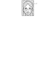
- FIG. 5 is a diagram showing an example of an input image that is one of learning data.
- FIG. 6 is a diagram showing an example of a target region image, which is one of learning data.
- FIG. 7 is a diagram showing an example of a shadow/highlight image created by the learning data processing device during processing.
- FIG. 1 is a block diagram showing an example of the configuration of a deep generative model learning system comprising a learning data processing device according to the first embodiment of the present invention.
- FIG. 2 is a diagram showing an example of
- FIG. 8 is a diagram showing another example of a shadow/highlight image.
- FIG. 9 is a diagram showing an example of a mask image.
- FIG. 10 is a diagram showing another example of the mask image.
- FIG. 11 is a diagram showing an example of a reverse shadow/highlight imparting area image to be combined.
- FIG. 12 is a diagram showing another example of a reverse shadow/highlight imparting area image to be combined.
- FIG. 13 is a diagram illustrating an example of a data augmented image created by the learning data processing device;
- FIG. 14 is a diagram showing another example of a data augmented image created by the learning data processing device.
- FIG. 15 is a flow chart showing an example of the processing operation of the learning data processing device according to the second embodiment of the present invention.
- FIG. 15 is a flow chart showing an example of the processing operation of the learning data processing device according to the second embodiment of the present invention.
- FIG. 16 is a block diagram showing an example of the configuration of a deep generative model learning system including a learning data processing device according to the third embodiment of the present invention.
- FIG. 17 is a flow chart showing an example of the processing operation of the learning data processing device according to the third embodiment.
- FIG. 1 is a block diagram showing an example of the configuration of a deep generative model learning system including a learning data processing device 100 according to the first embodiment of the present invention.
- the deep generative model learning system includes this learning data processing device 100 , a learning device 200 and a learning data storage unit 300 .
- the deep generative model learning system may be configured such that each of these units is integrated as one device or housing, or may be configured from a plurality of devices. Also, multiple devices may be remotely located and connected via a network.
- the learning data storage unit 300 stores learning data necessary for learning in the learning device 200.
- the learning data includes the input image and the lighting environment of the input image, the teacher image that is an image obtained by changing only the lighting environment from the input image, the lighting environment of the teacher image, and the brightness change target area, that is, the shadow or highlight in the input image. and a target area image showing the area to be applied (eg, a portion of a person's face).
- the lighting environment has, for example, either vector data using spherical harmonics or an environment map image expressing reflections around the image.
- One epoch is when all of the prepared learning data is transferred from the learning data storage unit 300 to the learning data processing device 100 once.
- the learning data processing device 100 performs data preprocessing including data extension on the learning data acquired from the learning data storage unit 300 .
- Data augmentation refers to a process of adding an image effect that simulates shadows or highlights to learning data.
- the learning data processing device 100 passes the preprocessed learning data to the learning device 200 .
- the learning device 200 uses the learning data passed from the learning data processing device 100 to learn the deep generative model.
- the learning device 200 uses the learned deep generation model to generate a re-illuminated image from an arbitrary input image.
- the input image may be acquired via the learning data processing device 100, or may be acquired via an input device or a network (not shown).
- the learning device 200 updates the parameters of the deep generative model and records the deep generative model by evaluating the generated re-illumination image and the learning data.
- the learning data processing device 100 includes a data input section 110, a data extension section 120 and a data output section .
- the data input unit 110 acquires the learning data, that is, the input image and the lighting environment of the input image, the teacher image and the lighting environment of the teacher image, and the target area image from the learning data storage unit 300 .
- the data input unit 110 passes the input image and the lighting environment of the input image and the teacher image and the lighting environment of the teacher image among the learning data to the data output unit 130 .
- the data input unit 110 uses random parameters to determine whether to perform data extension that increases the influence of illumination. Hand over to 120.
- the data extension unit 120 includes a luminance adjustment unit 121, a mask area creation unit 122, a mask image storage unit 123, and an image synthesis unit 124.
- the brightness adjustment unit 121 passes the input image passed from the data input unit 110 to the image synthesizing unit 124 . Also, the luminance adjustment unit 121 creates a shadow/highlight image, which is a luminance-adjusted image obtained by performing luminance adjustment on the input image. Then, the brightness adjustment unit 121 passes the created shadow/highlight image and the target region image passed from the data input unit 110 to the mask region generation unit 122 .
- the mask image storage unit 123 stores a mask image data set, which is a data set of irregular mask images.
- FIG. 2 is a diagram showing an example of this mask image data set.
- An existing data set may be used for the mask image, or an image created using Perlin noise may be used.
- the mask area creation unit 122 creates a shadow/highlight application area image indicating an area to be shaded or highlighted from the shadow/highlight image and the target area image passed from the brightness adjustment unit 121 and the mask image. do.
- the mask image may be a mask image stored in advance in the mask image storage unit 123, or may be created by subjecting the shadow/highlight image to arbitrary binarization processing.
- the mask area creation unit 122 can determine which of the pre-stored mask image and the created mask image is to be used using a random parameter.
- the mask area creating unit 122 passes the shadow/highlight image and the created shadow/highlight adding area image to the image synthesizing unit 124 .
- the image synthesizing unit 124 synthesizes the input image passed from the luminance adjusting unit 121, the shadow/highlight image and the shadow/highlight added area image passed from the mask area creating unit 122, and generates a data extension image. create.
- the image synthesizing unit 124 passes the created data augmented image to the data output unit 130 .
- the data output unit 130 normalizes or standardizes each of the input image and teacher image passed from the data input unit 110 when data extension is not performed. Then, the data output unit 130 passes the normalized or standardized input image and the lighting environment of the input image, and the normalized or standardized teacher image and the lighting environment of the teacher image to the learning device 200 as learning data.
- the data output unit 130 replaces the input image passed from the data input unit 110 with the data extended image passed from the image synthesis unit 124 of the data extension unit 120 . That is, in this case, the data output unit 130 normalizes or standardizes the input image rewritten to the data augmented image and the teacher image. Then, the data output unit 130 passes the normalized or standardized input image and the lighting environment of the input image, and the normalized or standardized teacher image and the lighting environment of the teacher image to the learning device 200 as learning data. That is, data output unit 130 passes new learning data different from the original learning data to learning device 200 .
- FIG. 3 is a diagram showing an example of the hardware configuration of the learning data processing device 100.
- the learning data processing device 100 includes a processor 11, a program memory 12, a data memory 13, an input/output interface 14, and a communication interface 15, for example.
- Program memory 12 , data memory 13 , input/output interface 14 and communication interface 15 are connected to processor 11 via bus 16 .
- the learning data processing device 100 may be composed of, for example, a general-purpose computer such as a personal computer.
- the processor 11 includes a multi-core/multi-threaded CPU (Central Processing Unit), and is capable of concurrently executing multiple pieces of information processing.
- a multi-core/multi-threaded CPU Central Processing Unit
- the program memory 12 includes, as a storage medium, a non-volatile memory such as a HDD (Hard Disk Drive) or an SSD (Solid State Drive) that can be written and read at any time, and a non-volatile memory such as a ROM (Read Only Memory). , and stores programs necessary for executing various control processes according to the first embodiment of the present invention by being executed by a processor 11 such as a CPU. That is, the processor 11 can function as the data input unit 110, the data expansion unit 120, and the data output unit 130 as shown in FIG. 1 by reading and executing the programs stored in the program memory 12.
- FIG. These processing function units may be realized by sequential processing of one CPU thread, or may be realized in a form in which simultaneous parallel processing is possible by separate CPU threads.
- these processing function units may be realized by separate CPUs. That is, the learning data processing device 100 may include multiple CPUs. In addition, at least some of these processing function units may include integrated circuits such as ASICs (Application Specific Integrated Circuits), FPGAs (field-programmable gate arrays), GPUs (Graphics Processing Units), and various other hardware circuits. may be implemented in the form of The programs stored in the program memory 12 can include a learning data processing program as shown in FIG.
- the data memory 13 uses, as a storage medium, a combination of a non-volatile memory such as an HDD or an SSD that can be written and read at any time, and a volatile memory such as a RAM (Random Access Memory). It is used to pre-store various data necessary for pre-processing data including
- a mask image data set storage area 13A for storing mask image data sets can be reserved. That is, the data memory 13 can function as the mask image storage unit 123 .
- a temporary storage area 13B can also be reserved for storing various data obtained and created during the process of pre-processing data including data extension.
- the input/output interface 14 is an interface with an input device such as a keyboard and mouse (not shown) and an output device such as a liquid crystal monitor.
- the input/output interface 14 may also include an interface with a memory card or disk medium reader/writer. If the mask image set is recorded on a memory card or disk medium and provided, the processor 11 can read it through the input/output interface 14 and store it in the mask image data set storage area 13A of the data memory 13. can.
- the communication interface 15 includes, for example, one or more wired or wireless communication interface units, and enables transmission and reception of various information with devices on the network according to the communication protocol used on the network.
- a wired interface for example, a wired LAN, a USB (Universal Serial Bus) interface, etc. are used.
- An interface that adopts the power wireless data communication standard, etc. is used.
- the processor 11 can receive and acquire learning data from the learning data storage unit 300 via the communication interface 15 .
- processor 11 can obtain mask image data sets from devices on the network.
- processor 11 can transmit learning data to learning device 200 via communication interface 15 .
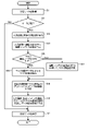
- FIG. 4 is a flowchart showing an example of the processing operation of the learning data processing device 100.
- FIG. When the user instructs execution of the learning data processing program from an input device (not shown) through the input/output interface 14, the processor 11 starts the operation shown in this flow chart. Alternatively, the processor 11 may start the operation shown in this flow chart in response to an execution instruction from the learning device 200 on the network via the communication interface.
- the processor 11 operates as the data input unit 110 to acquire learning data from the learning data storage unit 300 (step S11).
- the acquired learning data is stored in the temporary storage area 13B of the data memory 13 .
- the learning data includes the input image and the lighting environment of the input image, the teacher image and the lighting environment of the teacher image, and the target area image.
- step S12 determines whether or not to perform data expansion to increase the influence of illumination using random parameters. If data extension is not to be performed (NO in step S12), the processor 11 proceeds to the process of step S20, which will be described later.
- step S12 the processor 11 performs the operation as the luminance adjustment unit 121 and first acquires the input image and the target area image (step S13). . That is, the processor 11 reads out the input image and the target area image from the temporary storage area 13B. Passing the input image and the target area image from the data input unit 110 to the brightness adjustment unit 121 in the description of the configuration means saving and reading to the temporary storage area 13B in this manner. This also applies to the following description.
- FIG. 5 is a diagram showing an example of the input image I.
- FIG. 6 is a diagram showing an example of the target area image Mf .
- the processor 11 performs luminance adjustment on the entire input image I to create a shadow/highlight image (step S14).
- This brightness adjustment includes a brightness adjustment to decrease brightness when adding effect A simulating shadow as data extension, and a brightness adjustment increasing brightness when effect B simulating highlight is added as data extension.
- Brightness adjustment techniques may use, for example, linear correction and gamma correction, and are preselected by the user.
- the brightness adjustment parameter ⁇ the user sets the upper and lower limits in advance under the condition that ⁇ 1.0 for effect A and ⁇ >1.0 for effect B in both linear correction and gamma correction. and randomly determined within this range.
- a shadow/highlight image J whose luminance has been adjusted is created as shown in Equation 1 below.
- FIG. 7 is a diagram showing an example of a shadow/highlight image J that has undergone luminance adjustment in the case of adding an effect A imitating a shadow as data extension.
- the shadow/highlight image J in this case is a shadow image.
- FIG. 8 is a diagram showing an example of a shadow/highlight image J subjected to luminance adjustment in the case of adding an effect B simulating a highlight as data extension.
- the shadow/highlight image J in this case is a highlight image.
- the processor 11 stores the shadow/highlight image J thus created in the temporary storage area 13B.
- the processor 11 executes the operation as the mask area creating unit 122 and determines whether to use the mask image data set stored in advance in the mask image storage unit 123, that is, the mask image data set storage area 13A (step S15). ). That is, the processor 11 determines whether to use a mask image prepared in advance or to create a mask image from the shadow/highlight image J based on random parameters.
- the processor 11 acquires the mask image Md from the mask image data set stored in the mask image storage unit 123 using, for example, random parameters. (Step S16).
- FIG. 9 is a diagram showing an example of the acquired mask image Md .
- the processor 11 stores this acquired mask image Md in the temporary storage area 13B.
- the processor 11 selects the shadow/highlight image J stored in the temporary storage area 13B as data extension.
- a highlight image which is a shadow/highlight image J subjected to luminance adjustment when applying an effect B imitating , is read.
- the processor 11 creates a mask image Md by performing arbitrary binarization processing on the shadow/highlight image J (step S17).
- FIG. 10 is a diagram showing an example of a mask image Md created from this highlight image. The processor 11 stores this created mask image Md in the temporary storage area 13B.
- the processor 11 executes the operation as the image synthesizing unit 124, reads out the input image I, the shadow/highlight image J, and the shadow/highlight application area image M from the temporary storage area 13B, and converts them into the following numbers. 3 to create a data extended image I' (step S19).
- the shadow/highlight image J read here is a shadow image when the mask image Md is obtained from the mask image data set, a corresponding highlight image when the mask image Md is created from the shadow/highlight image J, becomes.
- the processor 11 can determine which shadow/highlight image J is to be read by storing it in the temporary storage area 13B in step S16 or step S17 and reading it. Alternatively, when the mask image Md is stored in the temporary storage area 13B in step S16 or S17, the shadow/highlight image J not used for image synthesis may be deleted from the temporary storage area 13B.
- FIG. 11 and 12 are diagrams showing an example of a reverse shadow/highlight imparting area image to be combined, indicated by 1-M in Equation 3.
- FIG. 11 corresponds to the mask image Md of FIG. 9, and
- FIG. 12 corresponds to the mask image Md of FIG.
- FIG. 13 shows a data augmented image I' created from the input image I, a shadow/highlight image J which is a shadow image, and the reversed shadow/highlight added area image 1-M in FIG. 12 shows a data augmented image I' created from I, a shadow/highlight image J which is a highlight image, and the reverse shadow/highlight imparting area image 1-M of FIG.
- the processor 11 then operates as the data output unit 130 and transmits learning data (step S20).
- step S12 the processor 11 reads out the input image and teacher image stored in the temporary storage area 13B, and normalizes or standardizes them. and store it again in the temporary storage area 13B. Then, the processor 11 reads out the input image, the lighting environment of the input image, and the teacher image and the lighting environment of the teacher image from the temporary storage area 13B, and transmits them to the learning device 200 via the communication interface 15 .
- the processor 11 stores the data in the temporary storage area 13B. read out the data augmented image I'. Then, the processor 11 normalizes or standardizes the data augmented image I', and saves the result as the input image I by overwriting the input image I already saved in the temporary storage area 13B. That is, the processor 11 rewrites the input image I stored in the temporary storage area 13B to the normalized or standardized data augmented image I'. The processor 11 also reads the teacher image stored in the temporary storage area 13B, normalizes or standardizes it, and stores it in the temporary storage area 13B again. Then, the processor 11 reads out the input image, the lighting environment of the input image, and the teacher image and the lighting environment of the teacher image from the temporary storage area 13B, and transmits them to the learning device 200 via the communication interface 15 .
- the data input unit 110 obtains the input image I and the lighting environment of the input image I from the learning data storage unit 300, and only the lighting environment from the input image I.
- Acquiring learning data used for learning a deep generative model including a teacher image that is a modified image, the lighting environment of the teacher image, and a target region image M f that indicates a brightness change target region in the input image I;
- the data extension unit 120 creates a shadow/highlight image J, which is a brightness adjusted image obtained by performing brightness adjustment on the input image I, and acquires or creates a mask image Md indicating a brightness change area to which brightness change is applied.
- the learning data processing device 100 uses the data output unit 130 to change the input image I in the learning data to the data augmented image I′ to create new learning data, and converts the new learning data into the deep generation model. It is output to the learning device 200 as learning data used for learning.
- the learning data processing apparatus 100 creates the data augmented image I′ based on the learning data, and creates new learning data including the data augmented image I′, so that the deep layer
- the number of pieces of learning data used for learning the generative model can be increased. Therefore, the learning device 200 can learn a deep generative model using learning data with increased influence of an irregular lighting environment, and realize learning of a deep generative model that is robust against shadows or highlights. becomes possible.
- the data extension unit 120 includes the brightness adjustment unit 121 that creates the shadow/highlight image J, which is a brightness adjusted image, by lowering the brightness of the entire input image I, and the target region image M f , the shadow/highlight image J and the mask image Md are combined to create a data augmented image I′ in which the portion corresponding to the luminance change area in the area corresponding to the luminance change target area in the input image I is darkened. and an image synthesizing unit 124 to create.
- the brightness adjustment unit 121 that creates the shadow/highlight image J, which is a brightness adjusted image, by lowering the brightness of the entire input image I, and the target region image M f , the shadow/highlight image J and the mask image Md are combined to create a data augmented image I′ in which the portion corresponding to the luminance change area in the area corresponding to the luminance change target area in the input image I is darkened.
- an image synthesizing unit 124 to create.
- the learning data processing apparatus 100 adds an image effect simulating a shadow to the learning data, thereby increasing the pattern of the lighting environment in the learning data in a pseudo manner. It is possible to realize robust deep generative model learning for shadows in the device 200 .
- the data extension unit 120 includes the brightness adjustment unit 121 that creates the shadow/highlight image J, which is a brightness adjustment image, by increasing the brightness of the entire input image I, and the target region image M f , the shadow/highlight image J and the mask image M d are combined to create a data augmented image I′ in which the portion corresponding to the luminance change area in the area corresponding to the luminance change target area in the input image I is brightened. and an image synthesizing unit 124 to create.
- the brightness adjustment unit 121 that creates the shadow/highlight image J, which is a brightness adjustment image, by increasing the brightness of the entire input image I, and the target region image M f , the shadow/highlight image J and the mask image M d are combined to create a data augmented image I′ in which the portion corresponding to the luminance change area in the area corresponding to the luminance change target area in the input image I is brightened.
- an image synthesizing unit 124 to create.
- the learning data processing apparatus 100 adds an image effect simulating a highlight to the learning data, thereby increasing the number of pseudo lighting environment patterns in the learning data. It is possible to realize robust deep generative model learning for highlights in the learning device 200 .
- the data expansion unit 120 includes the mask area creation unit 122 that creates the mask image Md by performing arbitrary binarization processing on the shadow/highlight image J, which is the brightness adjustment image. including.
- the learning data processing apparatus 100 creates a mask image Md based on the shadow/highlight image J, that is, the input image I, which is a luminance adjustment image, and uses this mask image Md . Since the data-extended image I' is generated as a result, the probability that the data-extended image I' deviating greatly from the input image I will be generated can be reduced.
- the data expansion unit 120 further extracts mask images from the mask image data set MIDS, which is a data set of irregular mask images stored in the mask image storage unit 123 in advance. It includes a mask region generator 122 that obtains M d .
- the learning data processing apparatus 100 can create the data augmented image I' using various mask images Md independent of the input image I, and the number of learning data can be reduced to It becomes possible to increase easily.
- a data-extended image obtained by adding an image effect simulating a shadow to the learning data, or a data-extended image I′ obtained by performing data extension adding an image effect simulating a highlight to the learning data. is creating That is, one of the data extension images I' is created. However, both of these two types of data extension images I' may be created.
- FIG. 15 is a flow chart showing an example of the processing operation of the learning data processing device according to the second embodiment of the present invention.
- the determination process of step S15 in the first embodiment is omitted, and the processor 11 obtains the mask image Md in step S16 and creates the mask image Md in step S17. do both.
- the processor 11 includes multi-threaded CPUs, these processes can be performed concurrently in separate threads.
- the process of step S16 and the process of step S17 may be performed sequentially. In this case, after performing the process of step S16, the process of step S17 may be performed, or the order may be reversed.
- step S18 the processor 11 creates two types of shadow/highlight addition area images M using the respective mask images M d , and in the process of step S19, two types of data extension images I ' to create.
- the processor 11 transmits learning data including these two types of data augmented images I' to the learning device 200 in step S20.
- the learning data processing apparatus 100 produces a shadow/highlight image J obtained by reducing the luminance of the entire input image I and a shadow/highlight image J obtained by increasing the luminance of the entire input image I. is used to obtain a data extension image I′ in which a portion corresponding to the brightness change region is darkened in the region corresponding to the brightness change target region in the input image I, and a data extension image in which a portion corresponding to the brightness change region is brightened Create an image I'.
- the learning data processing apparatus 100 adds image effects simulating shadows and highlights to the learning data, thereby increasing the number of pseudo lighting environment patterns in the learning data. This makes it possible to realize robust deep generative model learning for shadows and highlights in the learning device 200 .
- FIG. 16 is a block diagram showing an example of the configuration of a deep generative model learning system including the learning data processing device 100 according to the third embodiment of the present invention.
- a learning data processing apparatus 100 includes an evaluation unit 140 in addition to the configuration of the first embodiment. Then, the image synthesizing unit 124 of the data extension unit 120 adds the created data extension image I′ to the data output unit 130 and also passes it to the evaluation unit 140 .
- the evaluation unit 140 has an internal anomaly detection model and evaluates the data augmented image I'.
- the anomaly detection model consists of an image group A with shadows and highlights obtained from the actual image, and an image group B with shadows and highlights arbitrarily created so as to greatly deviate from the actual image. was used as learning data, and learning was performed using distance learning.
- the evaluation unit 140 acquires the data extension image I' from the data extension unit 120, inputs this data extension image I' to the anomaly detection model, and obtains an evaluation value. Then, when the evaluation value exceeds the threshold set by the user, the evaluation unit 140 regards the data extension image I′ as an image greatly deviating from the actual image, discards it, and returns the image to the data extension unit 120 again. , to perform data augmentation.
- FIG. 17 is a flow chart showing an example of the processing operation of the learning data processing device 100 according to the third embodiment. That is, following the processing of step S19, the processor 11 reads out the data augmented image I' stored in the temporary storage area 13B, and evaluates the data augmented image I' using the anomaly detection model learned in advance (step S31).
- step S32 determines whether the obtained evaluation value is equal to or less than the threshold. If the evaluation value is equal to or less than the threshold (YES in step S32), the data augmented image I' does not deviate greatly from the actual image, and is considered suitable for learning data of the learning device 200, and the process proceeds to step S20. . As a result, learning data including the data augmented image I′ is transmitted to the learning device 200 .
- the processor 11 temporarily determines that the data augmented image I′ is an image greatly deviating from the actual image.
- the data augmented image I' is deleted from the storage area 13B, and the process from step S13 is repeated. As a result, a new data augmented image I' can be created by changing the mask image.
- the evaluation unit 140 evaluates the data augmented image I′ created by the data extension unit 120, and the data augmented image I′ is larger than the actual image. If the image is a deviated image, the data extension unit 120 is caused to create the data extension image I′ again.
- the learning data processing device 100 evaluates the data augmented image I′ to create learning data that is not suitable for use in learning the deep generative model in the learning device 200. It is possible to prevent it from being done.
- the learning data processing device 100 may also include the evaluation unit 140 as in the third embodiment.
- the brightness adjustment unit 121 creates both a shadow image and a highlight image as the shadow/highlight image J, and the mask area creation unit 122 randomly selects one of them. shall be used for Instead of doing so, the brightness adjustment unit 121 randomly generates any image, and the mask area creation unit 122 uses a mask image corresponding to the shadow/highlight image J generated by the brightness adjustment unit 121. It is good to do.
- one data augmented image I' of one type is created, and in the second embodiment, two types of data augmented image I' are created one by one.
- the number of data extension images I' to be created may be increased by creating them.
- the shadow/highlight image J when the data augmented image I' is created in step S19, if the mask image Md has been obtained from the mask image data set, the shadow/highlight image J However, the highlight image may be used as the shadow/highlight image J in such a case as well. Which image to use as the shadow/highlight image J may be determined by a random parameter, or both may be used to create two types of data extension images I'.
- the learning data storage unit 300 may be configured as part of the learning data processing device 100 . That is, the data memory 13 may be provided with a storage area as the learning data storage unit 300 .
- the learning device 200 may incorporate the functions of the learning data processing device 100 of the embodiment.
- the method described in each embodiment can be executed by a computer (computer) as a program (software means), such as a magnetic disk (floppy (registered trademark) disk, hard disk, etc.), an optical disk (CD-ROM, DVD , MO, etc.), a semiconductor memory (ROM, RAM, flash memory, etc.), or the like, or may be transmitted and distributed via a communication medium.
- the programs stored on the medium also include a setting program for configuring software means (including not only execution programs but also tables and data structures) to be executed by the computer.
- a computer that realizes this apparatus reads a program recorded on a recording medium, and in some cases, builds software means by a setting program, and executes the above-described processes by controlling the operation by this software means.
- the term "recording medium" as used in this specification includes not only those for distribution, but also storage media such as magnetic disks, semiconductor memories, etc. provided in computers or devices connected via a network.
- the present invention is not limited to the above embodiments, and can be modified in various ways without departing from the gist of the invention at the implementation stage. Moreover, each embodiment may be implemented in combination as much as possible, in which case the combined effect can be obtained. Furthermore, the above-described embodiments include inventions at various stages, and various inventions can be extracted by appropriately combining a plurality of disclosed constituent elements.
Landscapes
- Engineering & Computer Science (AREA)
- Computer Vision & Pattern Recognition (AREA)
- Physics & Mathematics (AREA)
- General Physics & Mathematics (AREA)
- Theoretical Computer Science (AREA)
- Image Analysis (AREA)
Priority Applications (2)
| Application Number | Priority Date | Filing Date | Title |
|---|---|---|---|
| PCT/JP2021/014159 WO2022208843A1 (ja) | 2021-04-01 | 2021-04-01 | 学習データ処理装置、学習データ処理方法及び学習データ処理プログラム |
| JP2023510112A JPWO2022208843A1 (https=) | 2021-04-01 | 2021-04-01 |
Applications Claiming Priority (1)
| Application Number | Priority Date | Filing Date | Title |
|---|---|---|---|
| PCT/JP2021/014159 WO2022208843A1 (ja) | 2021-04-01 | 2021-04-01 | 学習データ処理装置、学習データ処理方法及び学習データ処理プログラム |
Publications (1)
| Publication Number | Publication Date |
|---|---|
| WO2022208843A1 true WO2022208843A1 (ja) | 2022-10-06 |
Family
ID=83458289
Family Applications (1)
| Application Number | Title | Priority Date | Filing Date |
|---|---|---|---|
| PCT/JP2021/014159 Ceased WO2022208843A1 (ja) | 2021-04-01 | 2021-04-01 | 学習データ処理装置、学習データ処理方法及び学習データ処理プログラム |
Country Status (2)
| Country | Link |
|---|---|
| JP (1) | JPWO2022208843A1 (https=) |
| WO (1) | WO2022208843A1 (https=) |
Cited By (1)
| Publication number | Priority date | Publication date | Assignee | Title |
|---|---|---|---|---|
| JP2024143813A (ja) * | 2023-03-30 | 2024-10-11 | 横河電機株式会社 | 装置、方法およびプログラム |
Citations (1)
| Publication number | Priority date | Publication date | Assignee | Title |
|---|---|---|---|---|
| JP2018161692A (ja) * | 2017-03-24 | 2018-10-18 | キヤノン株式会社 | 情報処理装置、情報処理方法およびプログラム |
-
2021
- 2021-04-01 WO PCT/JP2021/014159 patent/WO2022208843A1/ja not_active Ceased
- 2021-04-01 JP JP2023510112A patent/JPWO2022208843A1/ja active Pending
Patent Citations (1)
| Publication number | Priority date | Publication date | Assignee | Title |
|---|---|---|---|---|
| JP2018161692A (ja) * | 2017-03-24 | 2018-10-18 | キヤノン株式会社 | 情報処理装置、情報処理方法およびプログラム |
Cited By (1)
| Publication number | Priority date | Publication date | Assignee | Title |
|---|---|---|---|---|
| JP2024143813A (ja) * | 2023-03-30 | 2024-10-11 | 横河電機株式会社 | 装置、方法およびプログラム |
Also Published As
| Publication number | Publication date |
|---|---|
| JPWO2022208843A1 (https=) | 2022-10-06 |
Similar Documents
| Publication | Publication Date | Title |
|---|---|---|
| Chintha et al. | Recurrent convolutional structures for audio spoof and video deepfake detection | |
| CN110490960B (zh) | 一种合成图像生成方法及装置 | |
| US10901740B2 (en) | Synthetic depth image generation from cad data using generative adversarial neural networks for enhancement | |
| CN111275057B (zh) | 图像处理方法、装置及设备 | |
| JP6657137B2 (ja) | 情報処理装置、情報処理方法、及びプログラム | |
| JP6778670B2 (ja) | 情報処理装置、情報処理方法、及びプログラム | |
| KR20220098218A (ko) | 지도 학습을 위한 짝없는 데이터를 사용한 이미지-대-이미지 변환 | |
| CN109902018B (zh) | 一种智能驾驶系统测试案例的获取方法 | |
| US20170262623A1 (en) | Physics-based captcha | |
| CN113344777A (zh) | 基于三维人脸分解的换脸与重演方法及装置 | |
| CN107274358A (zh) | 基于cGAN算法的图像超分辨恢复技术 | |
| CN111310156B (zh) | 一种滑块验证码的自动识别方法及系统 | |
| CN116664422B (zh) | 图像高光处理方法、装置、电子设备及可读存储介质 | |
| JP7656721B2 (ja) | メディアアイテムからオブジェクトを細分化および除去すること | |
| KR102291041B1 (ko) | 게임 데이터 기반의 학습 장치 및 방법 | |
| US11170203B2 (en) | Training data generation method for human facial recognition and data generation apparatus | |
| WO2022208843A1 (ja) | 学習データ処理装置、学習データ処理方法及び学習データ処理プログラム | |
| CN114090968A (zh) | 用于数据集的所有权验证方法和装置 | |
| KR20220135890A (ko) | 인공지능 객체인식 모델을 위한 가상환경 기반 데이터 수집 방법 및 시스템 | |
| CN110070017B (zh) | 一种人脸假眼图像生成方法及装置 | |
| KR20230096901A (ko) | 자율 주행 차량의 학습을 위한 데이터 증식 방법 및 그를 위한 장치 | |
| CN114282651B (zh) | 光流预测模型的训练方法及系统和视频生成方法及系统 | |
| JP2023030207A (ja) | 学習装置、学習方法及び学習プログラム | |
| US20250336042A1 (en) | Lightweight image restoration | |
| US20250259346A1 (en) | Method, server, and computer program for generating relighted image based on object image |
Legal Events
| Date | Code | Title | Description |
|---|---|---|---|
| 121 | Ep: the epo has been informed by wipo that ep was designated in this application |
Ref document number: 21935005 Country of ref document: EP Kind code of ref document: A1 |
|
| WWE | Wipo information: entry into national phase |
Ref document number: 2023510112 Country of ref document: JP |
|
| NENP | Non-entry into the national phase |
Ref country code: DE |
|
| 122 | Ep: pct application non-entry in european phase |
Ref document number: 21935005 Country of ref document: EP Kind code of ref document: A1 |