WO2022208680A1 - Steering system for vehicle - Google Patents
Steering system for vehicle Download PDFInfo
- Publication number
- WO2022208680A1 WO2022208680A1 PCT/JP2021/013632 JP2021013632W WO2022208680A1 WO 2022208680 A1 WO2022208680 A1 WO 2022208680A1 JP 2021013632 W JP2021013632 W JP 2021013632W WO 2022208680 A1 WO2022208680 A1 WO 2022208680A1
- Authority
- WO
- WIPO (PCT)
- Prior art keywords
- steering
- angle
- steering angle
- control
- center
- Prior art date
- Legal status (The legal status is an assumption and is not a legal conclusion. Google has not performed a legal analysis and makes no representation as to the accuracy of the status listed.)
- Ceased
Links
Images



Classifications
-
- B—PERFORMING OPERATIONS; TRANSPORTING
- B62—LAND VEHICLES FOR TRAVELLING OTHERWISE THAN ON RAILS
- B62D—MOTOR VEHICLES; TRAILERS
- B62D6/00—Arrangements for automatically controlling steering depending on driving conditions sensed and responded to, e.g. control circuits
-
- B—PERFORMING OPERATIONS; TRANSPORTING
- B62—LAND VEHICLES FOR TRAVELLING OTHERWISE THAN ON RAILS
- B62D—MOTOR VEHICLES; TRAILERS
- B62D5/00—Power-assisted or power-driven steering
- B62D5/04—Power-assisted or power-driven steering electrical, e.g. using an electric servo-motor connected to, or forming part of, the steering gear
- B62D5/0457—Power-assisted or power-driven steering electrical, e.g. using an electric servo-motor connected to, or forming part of, the steering gear characterised by control features of the drive means as such
-
- B—PERFORMING OPERATIONS; TRANSPORTING
- B62—LAND VEHICLES FOR TRAVELLING OTHERWISE THAN ON RAILS
- B62D—MOTOR VEHICLES; TRAILERS
- B62D15/00—Steering not otherwise provided for
- B62D15/02—Steering position indicators ; Steering position determination; Steering aids
- B62D15/021—Determination of steering angle
- B62D15/0245—Means or methods for determination of the central position of the steering system, e.g. straight ahead position
-
- B—PERFORMING OPERATIONS; TRANSPORTING
- B62—LAND VEHICLES FOR TRAVELLING OTHERWISE THAN ON RAILS
- B62D—MOTOR VEHICLES; TRAILERS
- B62D5/00—Power-assisted or power-driven steering
- B62D5/001—Mechanical components or aspects of steer-by-wire systems, not otherwise provided for in this maingroup
- B62D5/005—Mechanical components or aspects of steer-by-wire systems, not otherwise provided for in this maingroup means for generating torque on steering wheel or input member, e.g. feedback
- B62D5/006—Mechanical components or aspects of steer-by-wire systems, not otherwise provided for in this maingroup means for generating torque on steering wheel or input member, e.g. feedback power actuated
-
- B—PERFORMING OPERATIONS; TRANSPORTING
- B62—LAND VEHICLES FOR TRAVELLING OTHERWISE THAN ON RAILS
- B62D—MOTOR VEHICLES; TRAILERS
- B62D5/00—Power-assisted or power-driven steering
- B62D5/04—Power-assisted or power-driven steering electrical, e.g. using an electric servo-motor connected to, or forming part of, the steering gear
- B62D5/0457—Power-assisted or power-driven steering electrical, e.g. using an electric servo-motor connected to, or forming part of, the steering gear characterised by control features of the drive means as such
- B62D5/046—Controlling the motor
-
- B—PERFORMING OPERATIONS; TRANSPORTING
- B62—LAND VEHICLES FOR TRAVELLING OTHERWISE THAN ON RAILS
- B62D—MOTOR VEHICLES; TRAILERS
- B62D6/00—Arrangements for automatically controlling steering depending on driving conditions sensed and responded to, e.g. control circuits
- B62D6/002—Arrangements for automatically controlling steering depending on driving conditions sensed and responded to, e.g. control circuits computing target steering angles for front or rear wheels
-
- B—PERFORMING OPERATIONS; TRANSPORTING
- B62—LAND VEHICLES FOR TRAVELLING OTHERWISE THAN ON RAILS
- B62D—MOTOR VEHICLES; TRAILERS
- B62D6/00—Arrangements for automatically controlling steering depending on driving conditions sensed and responded to, e.g. control circuits
- B62D6/008—Control of feed-back to the steering input member, e.g. simulating road feel in steer-by-wire applications
Definitions
- the present invention relates to a steer-by-wire steering system for a vehicle.
- a steer-by-wire steering system for a vehicle which includes a steering input mechanism such as a steering wheel configured to be operated by a vehicle operator, and a steering mechanism mechanically separated from the steering input mechanism and configured to change the steered angle of the wheels.
- the steering mechanism is driven by a steering actuator that generates a driving force to change the steering angle of the wheels.
- a reaction force actuator applies a reaction force to the steering input mechanism in response to the steering operation.
- a prior invention provides an improvement in the work efficiency in assembling a switch assembly including a steering angle sensor and a steering wheel to a steering shaft assembly (Patent Document 1).
- the steering shaft assembly is provided with a shaft positioning mechanism that positions and fixes the steering shaft to the housing in a rotationally fast manner.
- the switch assembly is provided with a collar positioning mechanism for positioning and fixing a pusher collar to the casing in a rotationally fast manner,
- a primary object of the present invention is to improve work efficiency when assembling a steering system without causing an increase in size or cost of the system.
- the output of the steering angle sensor can be corrected so that the steering angle (geometric steering center) at the time point of assembly corresponds to the control steering center by forwarding a prescribed input from the manual input switch to the control unit with the steering wheel positioned at the geometric steering center.
- the current steering angle (as determined by the angular position of the steering shaft) can be reset as the control steering center without the need for reassembling the steering wheel. Therefore, the work efficiency in assembling the steering system is improved. Further, since no physical positioning mechanism is required for the steering system, an increase in size and cost of the steering system can be avoided.
- control unit is configured to correct the output of the steering angle sensor when a predetermined time period has elapsed from a time point when the prescribed input is received, and temporarily stop driving the reaction force actuator until the predetermined time period has elapsed from the time point when the prescribed input is received.
- control unit may be configured to correct the output of the steering angle sensor when a predetermined time period has elapsed from a time point when the prescribed input is received, and temporarily reduce the target reaction force until the predetermined time period has elapsed from the time point when the prescribed input is received.
- control unit may be configured to correct the output of the steering angle sensor when a predetermined time period has elapsed from a time point when the prescribed input is received, and provide a dead zone in the deviation until the predetermined time period has elapsed from the time point when the prescribed input is received.
- the steering wheel is prevented from being turned by the reaction force actuator which may turn the steering wheel according to the steered state of the wheels under the control of the control unit.
- the worker is enabled to properly correct the output of the steering angle sensor without being hampered by the reaction force so that the geometrical steering center of the steering wheel coincides with the control steering center of the steering shaft.
- the steering system further comprises a physical stopper (43) that defines a physical maximum steering angle ( ⁇ mP) of the steering shaft in each rotational direction from the control steering center, and the control unit is configured to define a control maximum steering angle ( ⁇ mC) of the steering wheel in each rotational direction from the control steering center, the control maximum steering angle being smaller than the physical maximum steering angle, and drive the reaction force actuator so as to generate a steering limit reaction force (Tsl) that defines the control maximum steering angle.
- ⁇ mP physical maximum steering angle
- ⁇ mC control maximum steering angle
- Tsl steering limit reaction force
- the rotation of the steering shaft is regulated by the physical stopper so that problems such as damaging wire harness by excessive rotation of the steering shaft can be avoided.
- the control unit generates a steering limit reaction force to prevent the steering shaft from colliding with the physical stopper. As a result, the generation of collision noise and impact due to collision can be avoided. Since the maximum control angle of the steering wheel is set evenly each rotational direction from the control steering center, the maximum steering angle can be maintained to be even in both rotational directions.
- control unit sets the control maximum steering angle
- control unit prohibits correction of the output of the steering angle sensor when the prescribed input is received with the steering wheel set to a geometrical steering center thereof, and it is determined that the control maximum steering angle will exceed the physical maximum steering angle.
- the control unit prohibits the correction of the output of the steering angle sensor so that the maximum steering angle is prevented from becoming uneven in the two rotational directions.
- control unit sets the control maximum steering angle
- the control unit corrects the output of the steering angle sensor so that the current steering angle is brought closer to the control steering center as much as possible without causing the control maximum steering angle to exceed the physical maximum steering angle when the prescribed input is received with the steering wheel set to a geometrical steering center thereof, and it is determined that the control maximum steering angle will exceed the physical maximum steering angle.
- the geometrical steering center of the steering wheel can be brought as close to the control steering center of the steering wheel as possible without causing the control maximum steering angle to exceed the physical maximum steering angle.
- the control unit corrects the output of the steering angle sensor so that a geometrical steering center of the steering wheel coincides with the control steering center of the steering shaft, and change a ratio (K) of the steering angle to the steered angle to a smaller value so that the control maximum steering angle does not exceed the physical maximum steering angle when the prescribed input is received with the steering wheel set to the geometrical steering center, and it is determined that the control maximum steering angle will exceed the physical maximum steering angle.
- the output of the steering angle sensor is corrected so that the geometrical steering center of the steering wheel coincides with the mechanical steering sensor of the steering shaft.
- the steering system further includes a control steering center setting switch (37) provided in the vehicle for generating the prescribed input.
- a control steering center setting switch (37) provided in the vehicle for generating the prescribed input.
- the worker or the operator can easily correct the output of the steering angle sensor by operating the control steering center setting switch.
- the prescribed input may be an input from a vehicle diagnosis device (39) detachably connected to the vehicle.
- the user or the driver is prevented from accidentally correcting the output of the steering angle sensor while the vehicle is traveling.
- the present invention thus improves work efficiency when assembling a steering system without causing an increase in size or cost of the system.
- Figure 1 is a schematic diagram of a steering system according to an embodiment of the present invention.
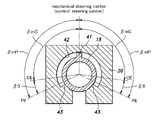
- Figure 2 is a simplified cross sectional view of a steering input mechanism.
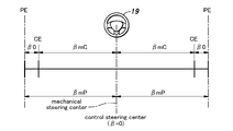
- Figure 3 is a schematic diagram illustrating an example of a relationship between a physical maximum steering angle and a control maximum steering angle when the steering input mechanism is correctly assembled.
- Figure 4 is a schematic diagram illustrating an example of output correction of a steering angle sensor in case of a small assembly error.
- Figure 5 is a schematic diagram illustrating a first example of output correction of the steering angle sensor in case of a large assembly error.
- Figure 6 is a schematic diagram illustrating a second example of output correction of the steering angle sensor in case of a large assembly error.
- Figure 7 is a schematic diagram illustrating a third example of output correction of the steering angle sensor in case of a large assembly error.
- a steering system 1 for a vehicle 2 is described in the following.
- the steering system 1 consists of a steer-by-wire (SBW) steering system.
- the vehicle 2 fitted with the steering system 1 is a four-wheeled vehicle having left and right front wheels 3 and left and right rear wheels (not shown in the drawings).
- the left and right front wheels 3 are supported by a vehicle body 8 (only the outline of a lower part thereof is shown in Figure 1) via respective knuckles 7 so that the steered angle ⁇ of the front wheels 3 can be changed, and the front wheels 3 thus serve as steerable wheels.
- the steered angle ⁇ refers to the angle of the front wheels 3 with respect to the fore and aft direction in plan view.
- the steering system 1 thus changes the steered angle ⁇ of the front wheels 3.
- the steering system 1 includes a steering input mechanism 10 rotatably provided on the vehicle body 8, a steering mechanism 11 for steering the front wheels 3, a steering actuator 12 for applying a driving force to the steering mechanism 11, a reaction force actuator 13 that applies a reaction torque T to the steering input mechanism 10, and a control unit 15 that controls the reaction force actuator 13 and the steering actuator 12.
- the steering system 1 may be a redundant system that includes a plurality of sets each individually provided with a steering actuator 12, a reaction force actuator 13, and a control unit 15.
- the steering input mechanism 10 accepts a steering operation by the vehicle operator.
- the steering input mechanism 10 includes a steering shaft 18 rotatably supported by the vehicle body 8 and a steering wheel 19 provided at an end of the steering shaft 18.
- the steering shaft 18 is rotatably supported by a steering column 20 provided on the vehicle body 8, and has a rear end thereof projecting rearward from the steering column 20.
- the steering wheel 19 is connected to the rear end of the steering shaft 18 so as to rotate integrally with the steering shaft 18.
- the steering shaft 18 is connected to the steering wheel 19 so as to transmit a rotational movement of the steering wheel 19 to the steering shaft 18.
- the reaction force actuator 13 consists of an electric motor which is connected to the steering shaft 18 via a gear mechanism. When the reaction force actuator 13 is driven, the driving force is transmitted to the steering shaft 18 as a rotational force. The reaction force actuator 13 applies a rotational torque to the steering input mechanism 10. The torque applied to the steering input mechanism 10 by the reaction force actuator 13 in response to the steering operation is called a reaction torque T.
- the steering system 1 is further provided with a steering angle sensor 21 that detects the rotational angle of the steering shaft 18 around the central axis thereof as a steering angle ⁇ .
- the steering angle is given as a rotational angle of the steering shaft 18 relative to a prescribed control steering center (which coincides with a mechanical steering center of the steering mechanism except for special cases which will be discussed hereinafter).
- the steering angle sensor 21 may be a per se known rotary encoder.
- the steering system 1 is provided with a torque sensor 22 that detects the torque applied to the steering shaft 18 as a steering torque Ts.
- the torque sensor 22 detects the steering torque Ts applied to a part of the steering shaft 18 located between the steering wheel 19 and the reaction force actuator 13.
- the steering torque Ts is determined by the operating torque applied to the steering wheel 19 by the vehicle operator and the reaction torque T applied to the steering shaft 18 by the reaction force actuator 13.
- the torque sensor 22 may consist of a per se known torque sensor such as a magnetostrictive torque sensor or a strain gauge, or, alternatively, the steering torque may be estimated from the value of the electric current flowing through the electric motor of the reaction force actuator 13.
- the steering system 1 further includes a first rotational angle sensor 23 that detects the rotational angle ⁇ of the reaction force actuator 13.
- the first rotational angle sensor 23 may be a per se known resolver or rotary encoder.
- the steering mechanism 11 has a rack 26 extending in the vehicle lateral direction.
- the rack 26 is supported by a gear housing 27 so as to be movable in the vehicle lateral direction.
- the left and right ends of the rack 26 are respectively connected to knuckles 7 that support the left and right front wheels 3 via respective tie rods 30.
- the steering mechanism 11 is mechanically separated from the steering input mechanism 10.
- the steering actuator 12 consists of an electric motor.
- the steering actuator 12 moves the rack 26 in the vehicle lateral direction according to the signal from the control unit 15, and changes the steered angle ⁇ of the left and right front wheels 3 accordingly.
- the steering system 1 is further provided with a second rotational angle sensor 31 that detects the rotational angle ⁇ of the steering actuator 12.
- the second rotational angle sensor 31 may be a per se known resolver or rotary encoder.
- the steering system 1 has a steered angle sensor 32 that detects the steered angle ⁇ of the front wheels 3.
- the steered angle sensor 32 consists of a rack stroke sensor that detects the rack position (the position of the rack 26 along the lateral direction of the vehicle), and the steered angle ⁇ of the front wheels 3 is determined from the rack position.
- the control unit 15 consists of an electronic control unit including a CPU, memory, a storage device for storing a program, and the like.
- the steering angle sensor 21, the torque sensor 22, the first rotational angle sensor 23, the second rotational angle sensor 31, and the steered angle sensor 32 are connected to the control unit 15. Based on the signals from these sensors, the control unit 15 acquires signals corresponding to the steering angle ⁇ , the steering torque Ts, the rotational angle ⁇ of the reaction force actuator 13, the rotational angle ⁇ of the steering actuator 12, and the steered angle ⁇ . Further, the control unit 15 is connected to a vehicle speed sensor 33, a yaw rate sensor 34, and a lateral acceleration sensor 35, and acquires signals corresponding to the vehicle speed V, the yaw rate ⁇ , and the lateral acceleration Gy.
- the control unit 15 is connected to the reaction force actuator 13 and the steering actuator 12 to control the reaction force actuator 13 and the steering actuator 12.
- the control unit 15 controls the steering actuator 12 according to the steering angle ⁇ , and controls the reaction force actuator 13 according to the steered angle ⁇ .
- the control unit 15 computes the target steered angle ⁇ t according to the steering angle ⁇ detected by the steering angle sensor 21.
- the gear ratio K may be preferably 2 to 30, and may be more preferably 8.
- control unit 15 performs a feedback control of the steering actuator 12 according to the deviation ⁇ .
- the first current value A1 supplied to the steering actuator 12 is increased, the output of the steering actuator 12 is increased, and the amount of change in the steered angle ⁇ is increased.
- the control unit 15 computes the target reaction torque Tt to be generated in the reaction force actuator 13 according to the steered state of the front wheels 3 in particular according to the deviation ⁇ .
- the target reaction torque Tt may be computed by multiplying ⁇ by a predetermined coefficient.
- the control unit 15 computes a second current value A2 to be supplied to the reaction force actuator 13 according to the computed target reaction torque Tt.
- the second current value A2 to be supplied to the reaction force actuator 13 may be determined in relation with the target reaction torque Tt by referring to a predetermined map.
- the control unit 15 may determine the second current value A2 according to the deviation ⁇ by referring to a predetermined map.
- the target reaction torque Tt and the second current value A2 are each greater in value as the deviation ⁇ of the steered angle ⁇ increases.
- the control unit 15 supplies the second current value A2 to the reaction force actuator 13, and generates a corresponding driving force in the reaction force actuator 13.
- the driving force generated by the reaction force actuator 13 is applied to the steering shaft 18 as a reaction torque T that opposes the operation input of the vehicle operator.
- the vehicle operator can receive a reaction force (resistance force) against the steering operation applied to the steering wheel 19.
- the vehicle 2 is provided with a control steering center setting switch 37 as a manual input switch for transmitting a steering center setting signal S to the control unit 15.
- the control steering center setting switch 37 is configured to accept a manual input, and to generate a steering center setting signal S when the manual input is received.
- the control steering center setting switch 37 may be provided in a vehicle diagnosis device 39 which is provided separately from the vehicle 2, and can be selectively connected to the control unit 15.
- FIG. 2 is a schematic cross-sectional view of the steering input mechanism 10.
- the steering shaft 18 is rotatably supported by the steering column 20.
- a protrusion 41 is formed on the outer surface of the steering shaft 18, and a receiving groove 42 for receiving the protrusion 41 is formed on the steering column 20.
- the receiving groove 42 is formed on the inner periphery of the steering column 20 over an angular range smaller than 360 degrees, and the end walls defining the respective ends of the receiving groove 42 form physical stoppers 43 that limit the movement of the protrusion 41.
- the protrusion 41 When the steering wheel 19 is turned clockwise, the protrusion 41 eventually comes into contact with the physical stopper 43 on the right side.
- the angular position where the protrusion 41 abuts on the physical stopper 43 on the right side is the physical end PE on the right side of the steering shaft 18.
- the protrusion 41 When the steering wheel 19 is turned counterclockwise, the protrusion 41 eventually comes into contact with the physical stopper 43 on the left side.
- the angular position where the protrusion 41 abuts on the physical stopper 43 on the left side is the physical end PE on the left side of the steering shaft 18.
- the center between the physical end PE on the right side and the physical end PE on the left side is the mechanical steering center of the steering shaft 18.
- the angular range from the mechanical steering center of the steering shaft 18 to the physical end PE on the right side is the physical maximum steering angle ⁇ mP on the right side
- the angular range from the mechanical steering center of the steering shaft 18 to the physical end PE on the left side is the physical maximum steering angle ⁇ mP on the left side.
- the left and right physical stoppers 43 each define the left or the right physical maximum steering angle ⁇ mP of the steering shaft 18.
- an impact noise is generated, and the impact may impair the mechanical durability of the steering input mechanism 10. It is therefore desirable to avoid such noise and the impairment of durability.
- the front wheels 3 can be steered only up to the physical end PE in each direction.
- the physical end PE can be defined in various ways, but is usually defined by the stroke end of the rack 26, commonly referred to as the "rack end".
- the center between the left and right stroke ends of the rack 26 is the mechanical steering center of the steering mechanism 11 which usually coincides with the position of the front wheels 3 when the vehicle is traveling straight, or when the steered angle ⁇ of the steering mechanism 11 is 0 °.
- a control end CE which is the control rotation limit of the steering shaft 18, is set for each rotational direction at an angle smaller than the angle of the physical end PE by an angle ⁇ 0.
- the control steering center should correspond to the geometric steering center of the steering wheel 19.
- the angular range from the control steering center of the steering shaft 18 to the control end CE on the right side is defined as the control maximum steering angle ⁇ mC on the right side
- the angular range from the control steering center of the steering shaft 18 to the control end CE on the left side is defined as the control maximum steering angle ⁇ mC on the left side.
- the target steered angle ⁇ t is related to the steering angle ⁇ in such a manner that the steered angle ⁇ of the front wheels 3 increases as the steering angle ⁇ increases.
- the command to the steering actuator 12 is limited to the control maximum steering angle corresponding to the control maximum steering angle ⁇ mC.
- the front wheels 3 are steered only up to the maximum control steered angle.
- the maximum control steered angle is smaller than the maximum physical steered angle.
- the reaction torque T that is applied to the steering input mechanism 10 is normally controlled so as to increase in dependence on the deviation ⁇ in the steered angle ⁇ from the target steered angle ⁇ t.
- the control unit 15 applies a steering limit reaction torque Tsl to the steering input mechanism 10 to prevent the steering input mechanism 10 from being turned beyond the control maximum steering angle ⁇ mC.
- the steering limit reaction torque Tsl is a value substantially greater than the normal value of the reaction torque T that could be generated in other situations.
- the control unit 15 computes a second current value A2 that is required to be supplied to the reaction force actuator 13 to generate the steering limit reaction torque Tsl.
- the steering limit reaction force torque Ts1 is applied to the steering input mechanism 10.
- the driver recognizes that the steered angle ⁇ of the front wheels 3 has reached the maximum angle due to the reaction force received from the steering input mechanism 10, and is thereby urged not to turn the steering input mechanism 10 excessively.
- the steering system 1 is provided with a physical stopper 43 that defines the physical maximum steering angle ⁇ mP on the left and right sides of the steering shaft 18. Therefore, problems such as damaging wire harness by excessive rotation of the steering shaft 18 can be avoided.
- control unit 15 sets a control maximum steering angle ⁇ mC smaller than the physical maximum steering angle ⁇ mP, and drives the reaction force actuator 13 so as to generate a steering limit reaction torque Tsl that defines the control maximum steering angle ⁇ mC.
- the control unit 15 generates the steering limit reaction torque Tsl, the steering shaft 18 is prevented from colliding with the physical stopper 43. As a result, the generation of collision noise and impact even when the steering wheel 19 is turned excessively. Since the maximum control steering angle ⁇ mC of the steering wheel 19 is set on each side of the geometric steering center of the steering wheel 19 (clockwise rotation and counter-clockwise rotation), the maximum steering angle of the steering wheel 19 is evenly distributed to the left and right.
- Figure 3 is a diagram showing the relationship between the physical maximum steering angle ⁇ mP and the control maximum steering angle ⁇ mC as a result of a proper assembly work.
- the steering wheel 19 is assembled to the steering shaft 18 properly so that the geometric steering center of the steering wheel 19 coincides with the mechanical steering center (which is the same as the control steering center in this case) of the steering shaft 18.
- the angular displacement of the steering wheel 19 from the geometric steering center as perceived by the drive are in agreement with each other.
- the steering wheel 19 may be assembled to the steering shaft 18 in such a manner that the geometric steering center of the steering wheel 19 is offset from the mechanical steering center of the steering shaft 18. It is also possible that the geometric steering center of the steering wheel 19 may be offset from the mechanical steering center of the steering shaft 18 when the steering wheel 19 is removed from the steering shaft 18 and reassembled during post-factory maintenance.
- Figure 4 is a diagram illustrating the process of correcting the output of the steering angle sensor 21 when a small assembly error was made when installing the steering wheel 19.
- the steering wheel 19 is assembled to the steering shaft 18 such that the steering wheel 19 is turned slightly to the left from the geometric steering center thereof when the steering shaft 18 is at the mechanical steering center.
- the steering wheel 19 is assembled to the steering shaft 18 such that the steering wheel 19 is at the geometrical steering center while the steering shaft 18 is slightly turned to the right from the mechanical steering center thereof.
- the person who has performed the assembly work can readily correct the output of the steering angle sensor 21 by operating the control steering center setting switch 37 and inputting the steering center setting signal S to the control unit 15. More specifically, the worker manually operates the control steering center setting switch 37 in a state where the steering wheel 19 is placed at the geometric steering center as shown in Figure 4 (B).
- the control steering center setting switch 37 When the control steering center setting switch 37 is operated, the steering center setting signal S is generated, and the steering center setting signal S is forwarded to the control unit 15.
- the worker can correct the output of the steering angle sensor 21 such that the steering angle ⁇ at that time is the value corresponding to the control steering center.
- the output of the steering angle sensor 21 can be reset to the value corresponding to the mechanical steering center while the steering wheel 19 is held at the geometrical steering center thereof without requiring the steering wheel 19 to be reassembled. Therefore, the work efficiency in assembling the steering system 1 can be improved. Further, since no physical positioning mechanism is required for the steering system 1, an increase in size and cost of the steering system 1 can be avoided.
- the control steering center setting switch 37 may be a switch provided on the vehicle 2 as described above. By providing the control steering center setting switch 37 in the vehicle 2, the worker can easily correct the output of the steering angle sensor 21 by operating the control steering center setting switch 37.
- control steering center setting switch 37 may be a switch provided in the vehicle diagnosis device 39 that is separate from the vehicle 2 as mentioned above.
- the vehicle diagnosis device 39 when the worker operates the control steering center setting switch 37 of the vehicle diagnosis device 39, the vehicle diagnosis device 39 generates the steering center setting signal S, and the steering center setting signal S is forwarded from the vehicle diagnosis device 39 to the control unit 15. Since the steering center setting signal S is an input from the vehicle diagnosis device 39 selectively connected to the vehicle 2, the user of the vehicle or the driver is prevented from erroneously correcting the output of the steering angle sensor 21, for instance, when the vehicle 2 is traveling.
- control unit 15 may correct the output of the steering angle sensor 21 such that the current steering angle corresponds to the mechanical steering center after elapsing of a prescribed time period from the time point of receiving the steering center setting signal S. Further, the control unit 15 may temporarily stop driving the reaction force actuator 13 until the prescribed time period has elapsed from the time point of receiving the steering center setting signal S.
- the steering wheel 19 is prevented from being turned by the reaction force which may be generated by the reaction force actuator 13 according to the steering state of the front wheels 3 under the control of the control unit 15. Therefore, the worker can correct the output of the steering angle sensor 21 such that the current steering angle corresponds to the control steering center while the steering wheel 19 is held at the geometric steering center without the fear of the reaction force disturbing this calibration process.
- control unit 15 may correct the output of the steering angle sensor 21 when a predetermined time has elapsed from the time when the prescribed input is received, and temporarily reduce the target reaction torque Tt from the time when the predetermined input is received until the predetermined time has elapsed.
- control unit 15 may set a dead zone in the deviation ⁇ between the target steered angle ⁇ t and the steered angle ⁇ that is used for setting the target reaction torque Tt from the time when the prescribed input is received until the predetermined time has elapsed.
- the steering wheel 19 is prevented from being turned by the reaction force actuator which may turn the steering wheel according to the steered state of the wheels under the control of the control unit 15.
- the worker is enabled to properly correct the output of the steering angle sensor 21 without being hampered by the reaction force so that the geometrical steering center of the steering wheel coincides with the mechanical steering center of the steering shaft.
- FIG 5 is an explanatory diagram of a first example of output correction of the steering angle sensor 21 in the case of a large assembly error.
- the steering wheel 19 is assembled to the steering shaft 18 with its geometric steering center significantly angularly deviated to the right from the mechanical steering center of the steering shaft 18 as compared with the case of Figure 4 (B).
- the control unit 15 corrects the output of the steering angle sensor 21 so that the current steering angle ⁇ is a value corresponding to the control steering center, the control maximum steering angle ⁇ mC exceeds the physical maximum steering angle ⁇ mP.
- the control end CE on the corresponding side is more advanced in angle than the corresponding physical end PE. Therefore, in such a case, the control unit 15 prohibits the correction of the output of the steering angle sensor 21.
- control unit 15 prohibits the correction of the output of the steering angle sensor 21 to prevent the maximum steering angle from becoming uneven between right and left.
- FIG 6 is an explanatory diagram of a second example of output correction of the steering angle sensor 21 in the case of a large assembly error.
- the steering wheel 19 is assembled to the steering shaft 18 such that the geometrical steering center of the steering wheel is significantly angularly deviated from the mechanical steering center of the steering shaft 18 to the right. Therefore, when the control unit 15 corrects the output of the steering angle sensor 21 so that the current steering angle ⁇ is a value corresponding to the control steering center, the control maximum steering angle ⁇ mC exceeds the physical maximum steering angle ⁇ mP.
- the control unit 15 corrects the output of the steering angle sensor 21 so that the current steering angle ⁇ is brought closer to the mechanical steering center as much as possible without causing the control maximum steering angle ⁇ mC to exceed the physical maximum steering angle ⁇ mP when the prescribed input is received with the current steering angle set to the geometric steering center. More specifically, the control unit 15 corrects the output of the steering angle sensor 21 so that the right control end CE is equal to or smaller in angle than the right physical end PE.
- the geometrical steering center of the steering wheel 19 can be brought practically as close to the control steering center as possible without causing the control maximum steering angle ⁇ mC to exceed the physical maximum steering angle ⁇ mP.
- FIG 7 is an explanatory diagram of a third example of output correction of the steering angle sensor 21 in the case of a large assembly error.
- the steering wheel 19 is assembled to the steering shaft 18 such that the geometrical steering center of the steering wheel is significantly angularly deviated from the mechanical steering center of the steering shaft 18 to the right. Therefore, when the control unit 15 corrects the output of the steering angle sensor 21 so that the current steering angle ⁇ is a value corresponding to the control steering center, the control maximum steering angle ⁇ mC exceeds the physical maximum steering angle ⁇ mP.
- the output of the steering angle sensor 21 is corrected so that the steering angle ⁇ of the steering shaft 18 is at the control steering center when the steering wheel is placed at the geometric steering center.
- the control unit 15 changes the ratio K so that the maximum control angle ⁇ mC is within the physical maximum steering angle ⁇ mP so that the maximum steered angle of the front wheels 3 is maintained, and the maximum steering angle is prevented from becoming uneven between the left and the right.
- the physical stopper 43 may be provided so that the steering shaft 18 can rotate over an angular range larger than 360 degrees.
- the physical stopper 43 may be provided so as to selectively protrude into the receiving groove 42.
- the physical stopper 43 may be eliminated so that the steering shaft 18 may be rotatable without limitation. In this case, since the physical end PE does not exist, it is not necessary to limit the correction as described with reference to Figures 5 to 7.
- control unit 15 may set the steering angle sensor 21 so that the average value of the steering angle ⁇ (which may be suitably weighted) during the prescribed time period starting from the time point of inputting the steering center setting signal S is set as the value corresponding to the mechanical steering center.
- each member and part can be appropriately changed without deviating from the gist of the present invention.
- all of the components shown in the above embodiments are not necessarily essential to the present invention, and can be appropriately selected and omitted without departing from the gist of the present invention.
- steering system 2 vehicle 3: front wheel 10: steering input mechanism 11: steering mechanism 12: steering actuator 13: reaction force actuator 15: control unit 18: steering shaft 19: steering wheel 20: steering column 21: steering angle sensor 32: steering angle sensor 37: control steering center setting switch 39: vehicle diagnosis device 43: physical stopper ⁇ : steered angle ⁇ t: target steered angle ⁇ : steering angle ⁇ mP: physical maximum steering angle ⁇ mC: control maximum steering angle T: reaction torque Tsl: steering limit reaction torque Tt: target reaction torque
Landscapes
- Engineering & Computer Science (AREA)
- Chemical & Material Sciences (AREA)
- Combustion & Propulsion (AREA)
- Transportation (AREA)
- Mechanical Engineering (AREA)
- Steering Control In Accordance With Driving Conditions (AREA)
- Power Steering Mechanism (AREA)
Abstract
Description
the steering angle β of the steering
3: front wheel 10: steering input mechanism
11: steering mechanism 12: steering actuator
13: reaction force actuator 15: control unit
18: steering shaft 19: steering wheel
20: steering column 21: steering angle sensor
32: steering angle sensor 37: control steering center setting switch
39: vehicle diagnosis device 43: physical stopper
α: steered angle αt: target steered angle
β: steering angle βmP: physical maximum steering angle
βmC: control maximum steering angle T: reaction torque
Tsl: steering limit reaction torque Tt: target reaction torque
Claims (10)
- A steering system for a vehicle, comprising:
a steering wheel configured to be operated by a driver;
a steering shaft connected to the steering wheel in a rotational movement transmitting manner;
a steering mechanism mechanically separated from the steering shaft, and configured to steer wheels of the vehicle;
a steering angle sensor that detects a steering angle about a control steering center given as an angular position of the steering shaft corresponding to a straight traveling state of the vehicle;
a steering actuator that provides a driving force to the steering mechanism;
a steered angle sensor that detects a steered angel of the wheels;
a reaction force actuator that applies a reaction force to the steering wheel in response to a steering operation; and
a control unit configured to determine a target steered angle according to the steering angle and drive the steering actuator so as to cause the steered angle to coincide with the target steered angle, and to determine a target reaction force according to a steered state of the wheels and drive the reaction force actuator so as to cause the reaction force to coincide with the target reaction force,
wherein the control unit is configured to correct an output of the steering angle sensor in such a manner that the current steering angle corresponds to the control steering center when a prescribed input is received. - The steering system for a vehicle according to claim 1, wherein the control unit is configured to correct the output of the steering angle sensor when a predetermined time period has elapsed from a time point when the prescribed input is received, and temporarily stop driving the reaction force actuator until the predetermined time period has elapsed from the time point when the prescribed input is received.
- The steering system for a vehicle according to claim 1, wherein the control unit is configured to correct the output of the steering angle sensor when a predetermined time period has elapsed from a time point when the prescribed input is received, and temporarily reduce the target reaction force until the predetermined time period has elapsed from the time point when the prescribed input is received.
- The steering system for a vehicle according to claim 1, wherein the control unit is configured to correct the output of the steering angle sensor when a predetermined time period has elapsed from a time point when the prescribed input is received, and provide a dead zone in the deviation until the predetermined time period has elapsed from the time point when the prescribed input is received.
- The steering system for a vehicle according to any one of claims 1 to 4, further comprising a physical stopper that defines a physical maximum steering angle of the steering shaft in each rotational direction,
wherein the control unit is configured to define a control maximum steering angle (βmC) of the steering wheel in each rotational direction from the control steering center, the control maximum steering angle being smaller than the physical maximum steering angle, and drive the reaction force actuator so as to generate a steering limit reaction force (Tsl) that defines the control maximum steering angle. - The steering system for a vehicle according to claim 5, wherein the control unit prohibits correction of the output of the steering angle sensor when the prescribed input is received with the steering wheel set to a geometrical steering center thereof, and it is determined that the control maximum steering angle will exceed the physical maximum steering angle.
- The steering system for a vehicle according to claim 5, wherein the control unit corrects the output of the steering angle sensor so that the current steering angle is brought closer to the control steering center as much as possible without causing the control maximum steering angle to exceed the physical maximum steering angle when the prescribed input is received with the steering wheel set to a geometrical steering center thereof, and it is determined that the control maximum steering angle will exceed the physical maximum steering angle.
- The steering system for a vehicle according to claim 5, wherein the control unit corrects the output of the steering angle sensor so that a geometrical steering center of the steering wheel coincides with the control steering center of the steering shaft, and change a ratio of the steering angle to the steered angle to a smaller value so that the control maximum steering angle does not exceed the physical maximum steering angle when the prescribed input is received with the steering wheel set to a geometrical steering center thereof, and it is determined that the control maximum steering angle will exceed the physical maximum steering angle.
- The steering system for a vehicle according to any one of claims 1 to 8, further comprising a control steering center setting switch provided in the vehicle for generating the prescribed input.
- The steering system for a vehicle according to any one of claims 1 to 8, wherein the prescribed input is an input from a vehicle diagnosis device detachably connected to the vehicle.
Priority Applications (5)
| Application Number | Priority Date | Filing Date | Title |
|---|---|---|---|
| CN202180045183.7A CN115916628B (en) | 2021-03-30 | 2021-03-30 | Steering system for vehicles |
| US18/002,568 US12528537B2 (en) | 2021-03-30 | 2021-03-30 | Steering system for vehicle |
| JP2022521097A JP7418562B2 (en) | 2021-03-30 | 2021-03-30 | vehicle steering system |
| PCT/JP2021/013632 WO2022208680A1 (en) | 2021-03-30 | 2021-03-30 | Steering system for vehicle |
| DE112021002439.6T DE112021002439T5 (en) | 2021-03-30 | 2021-03-30 | STEERING SYSTEM FOR VEHICLE |
Applications Claiming Priority (1)
| Application Number | Priority Date | Filing Date | Title |
|---|---|---|---|
| PCT/JP2021/013632 WO2022208680A1 (en) | 2021-03-30 | 2021-03-30 | Steering system for vehicle |
Publications (1)
| Publication Number | Publication Date |
|---|---|
| WO2022208680A1 true WO2022208680A1 (en) | 2022-10-06 |
Family
ID=75581571
Family Applications (1)
| Application Number | Title | Priority Date | Filing Date |
|---|---|---|---|
| PCT/JP2021/013632 Ceased WO2022208680A1 (en) | 2021-03-30 | 2021-03-30 | Steering system for vehicle |
Country Status (5)
| Country | Link |
|---|---|
| US (1) | US12528537B2 (en) |
| JP (1) | JP7418562B2 (en) |
| CN (1) | CN115916628B (en) |
| DE (1) | DE112021002439T5 (en) |
| WO (1) | WO2022208680A1 (en) |
Families Citing this family (5)
| Publication number | Priority date | Publication date | Assignee | Title |
|---|---|---|---|---|
| DE102020200861B4 (en) * | 2020-01-24 | 2023-10-12 | Robert Bosch Gesellschaft mit beschränkter Haftung | Method for operating a steering system |
| JP7495281B2 (en) * | 2020-06-18 | 2024-06-04 | 株式会社ジェイテクト | Steering gear |
| JP7400745B2 (en) * | 2021-01-15 | 2023-12-19 | トヨタ自動車株式会社 | Vehicle steering system |
| WO2023046273A1 (en) * | 2021-09-22 | 2023-03-30 | Thyssenkrupp Presta Ag | Method for controlling a steer-by-wire steering system of a road vehicle with feedback actuator position calibration |
| DE102024210162A1 (en) * | 2024-10-21 | 2026-04-23 | Volkswagen Aktiengesellschaft | Steer-by-wire steering system for a motor vehicle, motor vehicle and method for operating a steer-by-wire steering system |
Citations (4)
| Publication number | Priority date | Publication date | Assignee | Title |
|---|---|---|---|---|
| JP2010264942A (en) | 2009-05-18 | 2010-11-25 | Toyota Motor Corp | Steer-by-wire steering device |
| US20170305455A1 (en) * | 2014-10-17 | 2017-10-26 | Nsk Ltd. | Electric power steering apparatus |
| US20190367079A1 (en) * | 2018-06-01 | 2019-12-05 | Jtekt Corporation | Steering Control Device |
| US20210031831A1 (en) * | 2019-07-29 | 2021-02-04 | Toyota Motor Engineering & Manufacturing North America, Inc. | System and method for calibrating a steering wheel neutral position |
Family Cites Families (20)
| Publication number | Priority date | Publication date | Assignee | Title |
|---|---|---|---|---|
| US6097286A (en) * | 1997-09-30 | 2000-08-01 | Reliance Electric Technologies, Llc | Steer by wire system with feedback |
| US6705419B2 (en) * | 2002-01-30 | 2004-03-16 | Delphi Technologies, Inc. | Drive-by-wire steering systems having a center feel mechanism and methods of providing |
| US6895357B2 (en) * | 2002-09-30 | 2005-05-17 | Continental Teves, Inc. | Offset calibration of a semi-relative steering wheel angle sensor |
| JP4019918B2 (en) * | 2002-11-28 | 2007-12-12 | 日本精工株式会社 | Integrated design system for electric power steering system |
| US6691009B1 (en) * | 2003-01-13 | 2004-02-10 | Visteon Global Technologies, Inc. | System and method of controlling a vehicle steer-by-wire system applying multivariable decoupling control |
| JP4294573B2 (en) * | 2004-11-02 | 2009-07-15 | 本田技研工業株式会社 | Steering device |
| US7295907B2 (en) * | 2005-06-14 | 2007-11-13 | Trw Automotive U.S. Llc | Recovery of calibrated center steering position after loss of battery power |
| US8950520B2 (en) * | 2006-07-07 | 2015-02-10 | Hydro-Gear Limited Partnership | Front steering module for a zero turn radius vehicle |
| EP2020361B1 (en) | 2007-08-02 | 2012-06-27 | Nissan Motor Co., Ltd. | Vehicle steering control apparatus |
| CN102648119B (en) * | 2009-06-29 | 2016-01-20 | 沃尔沃拉斯特瓦格纳公司 | For the method and system at run duration assisting vehicle chaufeur |
| JP5430505B2 (en) * | 2010-06-25 | 2014-03-05 | トヨタ自動車株式会社 | Vehicle control device |
| JP5967208B2 (en) | 2012-09-28 | 2016-08-10 | 日産自動車株式会社 | Steering control device |
| JP5900659B2 (en) | 2013-01-11 | 2016-04-06 | 日産自動車株式会社 | Vehicle travel control apparatus and vehicle travel control method |
| DE102016009684A1 (en) | 2016-08-10 | 2018-02-15 | Thyssenkrupp Ag | Control of a steer-by-wire steering system |
| JP7133393B2 (en) * | 2018-08-23 | 2022-09-08 | 株式会社ジェイテクト | steering controller |
| JP7047738B2 (en) | 2018-12-07 | 2022-04-05 | 株式会社デンソー | Steering system |
| JP2020163989A (en) | 2019-03-29 | 2020-10-08 | 株式会社ジェイテクト | Steering control device |
| DE102019120205A1 (en) * | 2019-07-25 | 2021-01-28 | Zf Automotive Germany Gmbh | Rotation limiter, steering system and method for limiting a rotary movement in a steering system |
| US11724733B2 (en) * | 2020-09-23 | 2023-08-15 | Steering Solutions Ip Holding Corporation | Torque-based directional control in steer-by-wire steering systems |
| GB2601827B (en) * | 2020-12-14 | 2024-12-04 | Zf Automotive Uk Ltd | Steering column assembly |
-
2021
- 2021-03-30 DE DE112021002439.6T patent/DE112021002439T5/en active Pending
- 2021-03-30 CN CN202180045183.7A patent/CN115916628B/en active Active
- 2021-03-30 WO PCT/JP2021/013632 patent/WO2022208680A1/en not_active Ceased
- 2021-03-30 JP JP2022521097A patent/JP7418562B2/en active Active
- 2021-03-30 US US18/002,568 patent/US12528537B2/en active Active
Patent Citations (4)
| Publication number | Priority date | Publication date | Assignee | Title |
|---|---|---|---|---|
| JP2010264942A (en) | 2009-05-18 | 2010-11-25 | Toyota Motor Corp | Steer-by-wire steering device |
| US20170305455A1 (en) * | 2014-10-17 | 2017-10-26 | Nsk Ltd. | Electric power steering apparatus |
| US20190367079A1 (en) * | 2018-06-01 | 2019-12-05 | Jtekt Corporation | Steering Control Device |
| US20210031831A1 (en) * | 2019-07-29 | 2021-02-04 | Toyota Motor Engineering & Manufacturing North America, Inc. | System and method for calibrating a steering wheel neutral position |
Also Published As
| Publication number | Publication date |
|---|---|
| DE112021002439T5 (en) | 2023-04-06 |
| CN115916628A (en) | 2023-04-04 |
| US20230234637A1 (en) | 2023-07-27 |
| JP2023523115A (en) | 2023-06-02 |
| CN115916628B (en) | 2026-03-13 |
| JP7418562B2 (en) | 2024-01-19 |
| US12528537B2 (en) | 2026-01-20 |
Similar Documents
| Publication | Publication Date | Title |
|---|---|---|
| US12528537B2 (en) | Steering system for vehicle | |
| CN102105342B (en) | Vehicle steering device and control method thereof | |
| JP3185022B2 (en) | Vehicle steering system | |
| US12515734B2 (en) | Steering system for vehicle | |
| JP4788618B2 (en) | Vehicle steering system | |
| JP4941723B2 (en) | Vehicle steering system | |
| JP4421426B2 (en) | Steering device | |
| CN113815716A (en) | steering system | |
| JP7830797B2 (en) | Method for the operation of a vehicle's steering system | |
| JP4506509B2 (en) | Steering control device | |
| US20170240202A1 (en) | Steering system having a pressure sensor | |
| JP5018166B2 (en) | Steering device | |
| WO2023046270A1 (en) | Method for controlling a steer-by-wire steering system of a road vehicle with garage mode | |
| CN108382452A (en) | Bearing calibration, assembly method and motor vehicles | |
| CN114945504B (en) | Method for operating a steering system | |
| WO2021049001A1 (en) | Vehicle steering system | |
| JP4858694B2 (en) | Variable transmission ratio steering device | |
| JP3665487B2 (en) | Vehicle steering device | |
| JP4857627B2 (en) | Vehicle steering apparatus and vehicle steering method | |
| EP4442539A1 (en) | Motor control device for steer-by-wire steering device | |
| JP7507540B2 (en) | Control device for vehicle steering system | |
| JP2008062668A (en) | Vehicle steering device | |
| JP2003252223A (en) | Steering angle detection device | |
| JP2005162067A (en) | Steering gear for vehicle |
Legal Events
| Date | Code | Title | Description |
|---|---|---|---|
| ENP | Entry into the national phase |
Ref document number: 2022521097 Country of ref document: JP Kind code of ref document: A |
|
| 121 | Ep: the epo has been informed by wipo that ep was designated in this application |
Ref document number: 21720009 Country of ref document: EP Kind code of ref document: A1 |
|
| 122 | Ep: pct application non-entry in european phase |
Ref document number: 21720009 Country of ref document: EP Kind code of ref document: A1 |
|
| WWG | Wipo information: grant in national office |
Ref document number: 18002568 Country of ref document: US |