WO2022201941A1 - 投射装置および投射方法 - Google Patents
投射装置および投射方法 Download PDFInfo
- Publication number
- WO2022201941A1 WO2022201941A1 PCT/JP2022/005239 JP2022005239W WO2022201941A1 WO 2022201941 A1 WO2022201941 A1 WO 2022201941A1 JP 2022005239 W JP2022005239 W JP 2022005239W WO 2022201941 A1 WO2022201941 A1 WO 2022201941A1
- Authority
- WO
- WIPO (PCT)
- Prior art keywords
- light
- projection
- modulation
- modulator
- light source
- Prior art date
- Legal status (The legal status is an assumption and is not a legal conclusion. Google has not performed a legal analysis and makes no representation as to the accuracy of the status listed.)
- Ceased
Links
Images









Classifications
-
- G—PHYSICS
- G03—PHOTOGRAPHY; CINEMATOGRAPHY; ANALOGOUS TECHNIQUES USING WAVES OTHER THAN OPTICAL WAVES; ELECTROGRAPHY; HOLOGRAPHY
- G03B—APPARATUS OR ARRANGEMENTS FOR TAKING PHOTOGRAPHS OR FOR PROJECTING OR VIEWING THEM; APPARATUS OR ARRANGEMENTS EMPLOYING ANALOGOUS TECHNIQUES USING WAVES OTHER THAN OPTICAL WAVES; ACCESSORIES THEREFOR
- G03B21/00—Projectors or projection-type viewers; Accessories therefor
- G03B21/14—Details
- G03B21/142—Adjusting of projection optics
-
- G—PHYSICS
- G02—OPTICS
- G02F—OPTICAL DEVICES OR ARRANGEMENTS FOR THE CONTROL OF LIGHT BY MODIFICATION OF THE OPTICAL PROPERTIES OF THE MEDIA OF THE ELEMENTS INVOLVED THEREIN; NON-LINEAR OPTICS; FREQUENCY-CHANGING OF LIGHT; OPTICAL LOGIC ELEMENTS; OPTICAL ANALOGUE/DIGITAL CONVERTERS
- G02F1/00—Devices or arrangements for the control of the intensity, colour, phase, polarisation or direction of light arriving from an independent light source, e.g. switching, gating or modulating; Non-linear optics
- G02F1/01—Devices or arrangements for the control of the intensity, colour, phase, polarisation or direction of light arriving from an independent light source, e.g. switching, gating or modulating; Non-linear optics for the control of the intensity, phase, polarisation or colour
-
- G—PHYSICS
- G03—PHOTOGRAPHY; CINEMATOGRAPHY; ANALOGOUS TECHNIQUES USING WAVES OTHER THAN OPTICAL WAVES; ELECTROGRAPHY; HOLOGRAPHY
- G03B—APPARATUS OR ARRANGEMENTS FOR TAKING PHOTOGRAPHS OR FOR PROJECTING OR VIEWING THEM; APPARATUS OR ARRANGEMENTS EMPLOYING ANALOGOUS TECHNIQUES USING WAVES OTHER THAN OPTICAL WAVES; ACCESSORIES THEREFOR
- G03B21/00—Projectors or projection-type viewers; Accessories therefor
- G03B21/005—Projectors using an electronic spatial light modulator but not peculiar thereto
- G03B21/006—Projectors using an electronic spatial light modulator but not peculiar thereto using LCD's
-
- H—ELECTRICITY
- H04—ELECTRIC COMMUNICATION TECHNIQUE
- H04B—TRANSMISSION
- H04B10/00—Transmission systems employing electromagnetic waves other than radio-waves, e.g. infrared, visible or ultraviolet light, or employing corpuscular radiation, e.g. quantum communication
- H04B10/11—Arrangements specific to free-space transmission, i.e. transmission through air or vacuum
Definitions
- the present disclosure relates to projection devices and the like that project spatial light signals.
- optical signals propagating in space are transmitted and received without using media such as optical fibers.
- a projection optical system such as a projection lens is required for projecting a spatial light signal.
- Patent Document 1 discloses a projection display device including a phase modulation type spatial light modulator.
- the apparatus of Patent Document 1 includes light emitting means including a light source that emits coherent light, image light generating means that modulates the light emitted by the light emitting means to generate image light, and projection means that projects the image light.
- a phase modulation type spatial light modulator is arranged either between the light emitting means and the image light generating means or between the image light generating means and the projecting means.
- a projection lens system (also called a projection optical system) is used to project modulated light modulated by a spatial light modulator as projection light.
- a projection lens system also called a projection optical system
- An object of the present disclosure is to provide a projection device or the like that omits a projection optical system and can be miniaturized.
- a projection device includes a light source that emits parallel light, a spatial light modulator that includes a modulator that modulates the phase of the parallel light emitted from the light source, and a plurality of A modulation area is set, a phase image corresponding to projection light projected in a plurality of projection directions is set in each of the plurality of modulation areas, and the phase images corresponding to the projection light are set for the plurality of modulation areas. and a control unit that controls the light sources so that parallel light is emitted toward each of them.
- a plurality of modulation regions are set in a spatial light modulator modulation unit having a modulation unit that modulates the phase of parallel light emitted from a light source that emits parallel light, and a plurality of projection
- a phase image corresponding to the projection light projected toward the direction is set in each of the plurality of modulation regions, and parallel light is irradiated toward each of the plurality of modulation regions set with the phase image corresponding to the projection light.
- the light source is controlled so as to project the projection light modulated in each of the plurality of modulation regions.
- FIG. 1 is a conceptual diagram showing an example of the configuration of a projection device according to a first embodiment
- FIG. 4 is a conceptual diagram showing an example of an optical path of parallel light emitted from a light source of the projection device according to the first embodiment
- FIG. FIG. 4 is a conceptual diagram for explaining an example of an optical path of projection light modulated by a modulation section of a spatial light modulator of the projection device according to the first embodiment
- 4 is a conceptual diagram for explaining an example of an optical path of projection light projected from the projection device according to the first embodiment
- FIG. It is a conceptual diagram showing an example of a configuration of a projection device according to a second embodiment.
- FIG. 7 is a conceptual diagram showing an example of optical paths of parallel light emitted from the light source of the projection device according to the second embodiment
- FIG. 7 is a conceptual diagram showing an example of optical paths of reflected light reflected by a reflecting mirror of the projection device according to the second embodiment
- FIG. 10 is a conceptual diagram for explaining an example of an optical path of projection light modulated by a modulation section of a spatial light modulator of a projection device according to a second embodiment
- FIG. 10 is a conceptual diagram for explaining an example of an optical path of projection light projected from a projection device according to a second embodiment
- FIG. 11 is a conceptual diagram showing an example of the configuration of a projection device according to a third embodiment
- FIG. 11 is a conceptual diagram showing an example of an optical path of parallel light emitted from a light source of a projection device according to a third embodiment
- FIG. 12 is a conceptual diagram for explaining a composite image set on the display section of the spatial light modulator of the projection device according to the third embodiment
- FIG. 11 is a conceptual diagram for explaining an example of an optical path of projection light modulated by a modulation section of a spatial light modulator of a projection device according to a third embodiment
- FIG. 11 is a conceptual diagram for explaining an example of an optical path of projection light projected from a projection device according to a third embodiment
- FIG. 11 is a conceptual diagram for explaining an example of a focus position of projection light projected from a projection device according to a third embodiment; It is a conceptual diagram which shows an example of a structure of the projection apparatus which concerns on 4th Embodiment. It is a conceptual diagram which shows an example of position change of the light source of the projection apparatus which concerns on 4th Embodiment. It is a conceptual diagram which shows an example of position change of the light source of the projection apparatus which concerns on 4th Embodiment.
- FIG. 14 is a conceptual diagram showing another example of changing the position of the light source of the projection device according to the fourth embodiment; FIG. 14 is a conceptual diagram showing another example of changing the position of the light source of the projection device according to the fourth embodiment; FIG.
- FIG. 11 is a conceptual diagram showing an example of the configuration of a projection device according to a fifth embodiment;
- FIG. 11 is a conceptual diagram showing an example of the configuration of a projection device according to a sixth embodiment;
- FIG. 4 is a conceptual diagram for explaining an application example 1 of each embodiment;
- FIG. 10 is a conceptual diagram for explaining a projection device of application example 2 of each embodiment; It is a conceptual diagram for demonstrating the application example 2 of each embodiment.
- It is a block diagram showing an example of hardware constitutions which realize a control part of a projection device concerning each embodiment.
- the directions of arrows in the drawings show examples, and do not limit the directions of light and signals.
- the lines indicating the trajectory of light in the drawing are conceptual and do not accurately represent the actual traveling direction or state of light.
- changes in the traveling direction and state of light due to refraction, reflection, and diffusion at the interface between air and matter may be omitted, or a luminous flux may be represented by a single line.
- the projection apparatus of the present embodiment is used for optical space communication and distance measurement in which optical signals propagating in space (hereinafter also referred to as spatial optical signals) are transmitted and received without using a medium such as an optical fiber.
- the projection device of the present embodiment may be used for applications other than optical space communication and distance measurement as long as it is used for projecting spatial light.
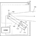
- FIG. 1 and 2 are conceptual diagrams showing an example of the configuration of the projection device 10 of this embodiment.
- Projection device 10 includes a plurality of light sources 11 , spatial light modulator 15 , and controller 17 .
- a plurality of light sources 11 and spatial light modulators 15 constitute a projection section 100 .
- FIG. 1 is a lateral view of the internal configuration of the projection device 10.
- FIG. 2 is a top view of the internal configuration of the projection device 10.
- FIG. 1 and 2 illustrate lines indicating the trajectory of light. 1 and 2 are conceptual, and do not accurately represent the positional relationship between components, the traveling direction of light, and the like. Although only a single light source 11 is shown in FIG.
- the projection device 10 of this embodiment includes a plurality of light sources 11 (11A, 11B, 11C) as shown in FIG.
- the light source 11A, the light source 11B, and the light source 11C are referred to as the light source 11 without the alphabet at the end.
- the light source 11 includes an emitter 111 and a collimator 112.
- the emitter 111 emits laser light 101 in a predetermined wavelength band under the control of the controller 17 .
- the wavelength of laser light 101 emitted from light source 11 is not particularly limited.
- the emitter 111 emits laser light 101 in the visible or infrared wavelength band.
- near-infrared rays of 800 to 900 nanometers (nm) can raise the laser class, so the sensitivity can be improved by about an order of magnitude compared to other wavelength bands.
- GaN gallium arsenide
- infrared laser light 101 in a wavelength band of 1.55 micrometers ( ⁇ m) can be emitted.
- a high output laser light source of about 100 milliwatts (mW) can be used.
- mW milliwatts
- the collimator 112 converts the laser light 101 emitted from the emitter 111 into parallel light 102 .
- Laser light 101 emitted from emitter 111 is converted into parallel light 102 by collimator 112 and emitted from light source 11 .
- the parallel light 102 emitted from the light source 11 travels toward the modulation section 150 of the spatial light modulator 15 .
- the incident angle of the parallel light 102 is set non-perpendicular to the modulating section 150 of the spatial light modulator 15 .
- the emission axis of the parallel light 102 emitted from the light source 11 is oblique to the modulation section 150 of the spatial light modulator 15 .
- the spatial light modulator 15 has a modulating section 150 irradiated with the parallel light 102 .
- the modulating section 150 is divided into a plurality of modulating regions associated with each of the plurality of light sources 11 .
- modulating section 150 is divided into modulating area 155A, modulating area 155B, and modulating area 155C.
- each of the plurality of modulation regions 155 set in the modulation section 150 is irradiated with the parallel light 102 emitted from each of the plurality of light sources 11 .
- the parallel light 102A emitted from the light source 11A is applied to the modulation area 155A.
- the parallel light 102B emitted from the light source 11B is applied to the modulation area 155B.
- the parallel light 102C emitted from the light source 11C is applied to the modulation area 155C.
- a pattern (also referred to as a phase image) corresponding to the image to be displayed is set according to the control of the control section 17. .
- a phase image for displaying the same image may be set, or a phase image for displaying a different image may be set.
- Light modulated by a plurality of modulation regions 155 set in the modulation section 150 of the spatial light modulator 15 is projected as projection light 105 .
- FIG. 3 is a conceptual diagram for explaining an example of projection of the projection light 105 modulated by the plurality of modulation areas 155 set in the modulation section 150.
- FIG. The parallel light 102 irradiated onto each of the plurality of modulation regions 155 is projected in a projection direction corresponding to the incident direction of the parallel light 102 at a diffraction angle corresponding to the pixel pitch and wavelength.
- the parallel light 102A irradiated onto the modulation area 155A is modulated by the modulation area 155A and projected as projection light 105A.
- the parallel light 102B irradiated to the modulation area 155B is modulated by the modulation area 155B and projected as projection light 105B.
- the parallel light 102C applied to the modulation area 155C is modulated by the modulation area 155C and projected as projection light 105C.
- each of the plurality of projection lights 105 modulated by the plurality of modulation regions 155 are projected in different projection directions so as not to overlap each other.
- Each of the plurality of projected lights 105 may overlap each other or may be spaced apart.
- the projection direction of each of the plurality of projection lights 105 is arbitrarily set.
- FIG. 4 is a conceptual diagram for explaining an example of the projection surface 180 on which an image corresponding to the projection light 105 modulated by the plurality of modulation regions 155 is displayed.
- An image corresponding to projection light 105A modulated by modulation region 155A is displayed on projection surface 180A.
- An image corresponding to projection light 105B modulated by modulation region 155B is displayed on projection surface 180B.
- An image corresponding to projection light 105C modulated by modulation region 155C is displayed on projection surface 180C.
- the images formed by the plurality of projection lights 105 modulated by the plurality of modulation regions 155 are displayed within a range that does not overlap each other.
- the images formed by the multiple projected lights 105 may overlap each other or may be displayed on spaced projection surfaces 180 .
- a projection surface 180 on which an image formed by a plurality of projection lights 105 is displayed is arbitrarily set.
- the spatial light modulator 15 is realized by a spatial light modulator using ferroelectric liquid crystal, homogeneous liquid crystal, vertically aligned liquid crystal, or the like.
- the spatial light modulator 15 can be realized by LCOS (Liquid Crystal on Silicon).
- the spatial light modulator 15 may be implemented by a MEMS (Micro Electro Mechanical System).
- the phase modulation type spatial light modulator 15 the energy can be concentrated on the image portion by sequentially switching the location where the projection light 105 is projected. Therefore, when the phase modulation type spatial light modulator 15 is used, if the output of the light source 11 is the same, the image can be displayed brighter than in other methods.
- the modulation section 150 of the spatial light modulator 15 is divided into a plurality of modulation regions 155 (also called tiling).
- the modulation section 150 is divided into rectangular modulation regions 155 (also called tiles) of the desired aspect ratio.
- a phase image generated by iterative Fourier transform is assigned to each of the plurality of tiles set in the modulation unit 150 .
- Each of the multiple tiles is composed of multiple pixels.
- a phase image corresponding to the image to be projected is set in each of the plurality of tiles.
- the phase images set for each of the plurality of tiles may be the same or different.
- each of the tiles is composed of 256 ⁇ 256 pixels or 512 ⁇ 512 pixels.
- the number of pixels forming a tile is set to the n-th power of 2 resolution (n is a natural number) in order to improve the calculation speed of the phase image.
- a phase image generated by iterative Fourier transform is tiled on each of the plurality of tiles assigned to the modulation unit 150 .
- each of the plurality of tiles is set with a pre-generated phase image.
- the projection light 105 forming an image corresponding to the phase image of each tile is emitted.
- the more tiles set in the modulation unit 150 the clearer the image can be displayed, but the lower the number of pixels in each tile, the lower the resolution. Therefore, the size and number of tiles set in the modulation section 150 are set according to the application. For example, if the number of tiles is less than 6, the projected image may be disturbed, so the number of tiles is preferably set to 6 or more.
- the control unit 17 controls the light source 11 and the spatial light modulator 15 .
- the control unit 17 is implemented by a microcomputer including a processor and memory.
- the control unit 17 sets the phase image corresponding to the image to be projected in the modulation unit 150 according to the tiling aspect ratio set in the modulation unit 150 of the spatial light modulator 15 .
- the control unit 17 individually sets phase images in each of the plurality of modulation regions 155 assigned to the modulation unit 150 .
- the control unit 17 individually sets a phase image corresponding to an image according to a purpose such as image display, communication, distance measurement, etc., in each of the plurality of modulation regions 155 assigned to the modulation unit 150 .
- the phase image of the image to be projected may be stored in advance in a storage unit (not shown).
- the shape and size of the projected image are not particularly limited.
- the control unit 17 adjusts the spatial light so that the parameter that determines the difference between the phase of the parallel light 102 irradiated to the modulating unit 150 of the spatial light modulator 15 and the phase of the projection light 105 reflected by the modulating unit 150 is changed. Drive the modulator 15 .
- a parameter that determines the difference between the phase of the parallel light 102 irradiated to the modulating section 150 of the spatial light modulator 15 and the phase of the projection light 105 reflected by the modulating section 150 is an optical parameter such as a refractive index or an optical path length. It is a parameter related to physical characteristics.
- the control section 17 adjusts the refractive index of the modulation section 150 by changing the voltage applied to the modulation section 150 of the spatial light modulator 15 .
- the parallel light 102 irradiated to the modulating section 150 is properly diffracted based on the refractive index of each section of the modulating section 150 . That is, the phase distribution of the parallel light 102 irradiated to the modulating section 150 of the phase modulation type spatial light modulator 15 is modulated according to the optical characteristics of the modulating section 150 .
- the method of moving the spatial light modulator 15 by the controller 17 is determined according to the modulation method of the spatial light modulator 15 .
- the control unit 17 drives the emitter 111 of the light source 11 with the phase image corresponding to the displayed image set in each of the plurality of modulation regions 155 assigned to the modulation unit 150 .
- the modulation section 150 of the spatial light modulator 15 is irradiated with the parallel light 102 emitted from the light source 11 in accordance with the timing at which the phase images are set in each of the plurality of modulation regions 155 .
- the parallel light 102 irradiated to each of the multiple modulation regions 155 is modulated in each modulation region 155 .
- the projection light 105 modulated in each of the multiple modulation regions 155 is projected from the projection device 10 toward the projection surface 180 associated with the projection light 105 .
- the projection device of this embodiment includes a plurality of light sources, spatial light modulators, and a controller.
- a plurality of light sources and spatial light modulators constitute a projection section.
- a plurality of light sources are associated with each of a plurality of modulation regions set in the modulation section of the spatial light modulator.
- Each of the plurality of light sources is arranged to emit parallel light toward the associated modulation region.
- Each of the plurality of light sources emits parallel light toward the associated modulation region.
- the spatial light modulator has a modulating section that modulates the phases of parallel lights emitted from a plurality of light sources.
- the controller sets a plurality of modulation areas in the modulation section of the spatial light modulator.
- the controller sets a phase image corresponding to projection light projected in a plurality of projection directions in each of the plurality of modulation regions.
- the controller controls each of the plurality of light sources so that parallel light is emitted toward each of the plurality of modulation regions in which the phase images corresponding to the projected light are set.
- the projection apparatus of this embodiment projects the light in the Fraunhofer region modulated by the modulation unit of the spatial light modulator without using a projection optical system. Therefore, according to this embodiment, it is possible to realize a compact projection apparatus in which a projection optical system is omitted.
- the projection device of this embodiment includes a reflecting mirror that reflects parallel light emitted from the light source toward a plurality of modulation areas set in the display section of the spatial light modulator.
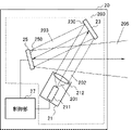
- FIG. 5 is a conceptual diagram showing an example of the configuration of the projection device 20 of this embodiment.
- the projection device 20 has a light source 21 , a reflector 23 , a spatial light modulator 25 and a controller 27 .
- Light source 21 , reflector 23 , and spatial light modulator 25 constitute projection section 200 .
- FIG. 5 is a lateral view of the internal configuration of the projection device 20. As shown in FIG.
- the light source 21 includes an emitter 211 and a collimator 212.
- the emitter 211 emits laser light 201 in a predetermined wavelength band under the control of the controller 27 .
- the collimator 212 converts the laser light 201 emitted from the emitter 211 into parallel light 202 .
- the emitter 211 has the same configuration as the emitter 111 of the first embodiment.
- the collimator 212 has the same configuration as the collimator 112 of the first embodiment.
- Laser light 201 emitted from emitter 211 is converted into parallel light 202 by collimator 212 and emitted from light source 21 .
- a parallel light 202 emitted from the light source 21 travels toward the reflecting surface 230 of the reflecting mirror 23 .
- the reflecting mirror 23 has a reflecting surface 230 that reflects the parallel light 202 emitted from the light source 21 .
- Reflecting surface 230 of reflecting mirror 23 reflects parallel light 202 emitted from light source 21 toward modulating section 250 of spatial light modulator 25 .
- Each of the reflecting areas 230 of the reflecting mirror 23 is associated with each of the plurality of reflecting areas.
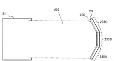
- FIG. 6 is a conceptual diagram showing an example in which the parallel light 202 emitted from the light source 21 is irradiated onto a plurality of reflecting areas 235 formed on the reflecting surface 230 of the reflecting mirror 23.
- parallel light 202 is assumed to travel from light source 21 toward reflecting surface 230 of reflecting mirror 23 .
- a reflective area 235A, a reflective area 235B, and a reflective area 236C are formed on the reflective surface 230 .
- Reflective area 235A, reflective area 235B, and reflective area 236C are formed at an angle to each other so as to reflect parallel light 202 from the light source in different directions.
- FIG. 7 is a conceptual diagram for explaining the optical path of the reflected light 203 of the parallel light 202 reflected by the reflecting surface 230 of the reflecting mirror 23.
- the modulation section 250 of the spatial light modulator 25 is divided into a plurality of modulation regions 255 .
- Reflected light 203 reflected by each of the plurality of reflection areas 235 on the reflecting surface 230 of the reflector 23 travels toward the modulation area 255 associated with each of the plurality of reflection areas 235 .
- Reflected light 203A travels toward modulation region 255A.
- Reflected light 203B travels toward modulation region 255B.
- Reflected light 203C travels toward modulation region 255C.
- the spatial light modulator 25 has a modulating section 250 irradiated with the reflected light 203 .
- the modulating section 250 is divided into a plurality of modulating regions 255 associated with each of the plurality of reflective regions 235 .
- modulation section 250 is divided into modulation region 255A, modulation region 255B, and modulation region 255C.
- a pattern also referred to as a phase image
- the spatial light modulator 25 has the same configuration as the spatial light modulator 15 of the first embodiment.
- each of the plurality of modulation regions 255 set in the modulation section 250 is irradiated with the reflected light 203 reflected by each of the plurality of reflection regions 235 .
- Reflected light 203B reflected by reflective area 235B is applied to modulation area 255B.
- Reflected light 203C reflected by reflective area 235C is applied to modulation area 255C.
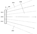
- FIG. 8 is a conceptual diagram for explaining an example of projection of projection light 205 modulated by a plurality of modulation regions 255.
- FIG. The parallel light 202 irradiated onto each of the plurality of modulation regions 255 is projected in a projection direction corresponding to the incident direction of the parallel light 202 at a diffraction angle corresponding to the pixel pitch and wavelength.
- the parallel light 202 applied to the modulation area 255A is modulated by the modulation area 255A and projected as projection light 205A.
- the parallel light 202 applied to the modulation area 255B is modulated by the modulation area 255B and projected as projection light 205B.
- the parallel light 202 applied to the modulation area 255C is modulated by the modulation area 255C and projected as projection light 205C.
- each of the plurality of projection lights 205 modulated by the plurality of modulation regions 255 are projected in different projection directions so as not to overlap each other.
- Each of the plurality of projected lights 205 may overlap each other or may be spaced apart.
- the projection direction of each of the plurality of projection lights 205 is arbitrarily set.
- FIG. 9 is a conceptual diagram for explaining an example of a projection surface 280 on which an image corresponding to projection light 205 modulated by multiple modulation regions 255 is displayed.
- An image corresponding to projection light 205A modulated by modulation region 255A is displayed on projection surface 280A.
- An image corresponding to projection light 205B modulated by modulation region 255B is displayed on projection surface 280B.
- An image corresponding to projection light 205C modulated by modulation region 255C is displayed on projection surface 280C.
- images formed by the plurality of projection lights 205 modulated by the plurality of modulation regions 255 are displayed within a range that does not overlap each other.
- the images formed by multiple projected lights 205 may overlap each other or may be displayed on spaced projection surfaces 280 .
- a projection surface 280 on which an image formed by a plurality of projection lights 205 is displayed is arbitrarily set.
- a control unit 27 controls the light source 21 and the spatial light modulator 25 .
- the control unit 27 is implemented by a microcomputer including a processor and memory.
- the controller 27 has the same configuration as the controller 17 of the first embodiment.
- the control unit 27 drives the emitter 211 of the light source 21 with the phase image corresponding to the displayed image set in each of the plurality of modulation regions 255 assigned to the modulation unit 250 .
- the modulation section 250 of the spatial light modulator 25 is irradiated with the reflected light 203 corresponding to the parallel light 202 emitted from the light source 21 in accordance with the timing at which the phase images are set in each of the plurality of modulation regions 255. be done.
- Reflected light 203 applied to each of the multiple modulation regions 255 is modulated in each modulation region 255 .
- the projection light 205 modulated in each of the multiple modulation regions 255 is projected from the projection device 20 toward the projection surface 280 associated with the projection light 205 .
- the projection device of this embodiment includes a light source, a reflector, a spatial light modulator, and a controller.
- the light source, reflector, and spatial light modulator constitute a projection section.
- the light source emits parallel light.
- the reflecting mirror has a plurality of reflecting areas associated with each of the plurality of modulation areas set in the modulating section of the spatial light modulator.
- the reflecting mirror is arranged so as to reflect parallel light emitted from the light source toward the plurality of modulation regions in the plurality of reflection regions associated with each of the plurality of modulation regions.
- the spatial light modulator has a modulating section that modulates the phase of reflected light reflected by each of the plurality of reflective areas.
- the controller sets a plurality of modulation areas in the modulation section of the spatial light modulator.
- the controller sets a phase image corresponding to projection light projected in a plurality of projection directions in each of the plurality of modulation regions.
- the control unit controls the light source so that parallel light is emitted toward each of the plurality of modulation regions in which the phase image corresponding to the projection light is set.
- the projection apparatus of this embodiment projects the light in the Fraunhofer region modulated by the modulation unit of the spatial light modulator without using a projection optical system. Therefore, according to this embodiment, it is possible to realize a compact projection apparatus in which a projection optical system is omitted.
- the projection apparatus of this embodiment includes a 0th-order light remover that blocks 0th-order light that may be included in projection light.
- a zero-order light remover is added to the projection apparatus of the first embodiment will be described below.
- a zero-order light remover may be added to the projection apparatus of the second embodiment.
- FIGS. 10 and 11 are conceptual diagrams showing an example of the configuration of the projection device 30 of this embodiment.
- Projection device 30 includes a plurality of light sources 31 , spatial light modulator 35 , zero-order light remover 36 , and controller 37 .
- a plurality of light sources 31 , zero-order light remover 36 , and spatial light modulator 35 constitute projection section 300 .
- FIG. 10 is a lateral view of the internal configuration of the projection device 30.
- FIG. 11 is a top view of the internal configuration of the projection device 30.
- FIG. 10 and 11 illustrate lines indicating the trajectory of light.
- FIGS. 10 and 11 are conceptual and do not accurately represent the positional relationship between constituent elements, the traveling direction of light, and the like.
- the projection device 30 of this embodiment includes a plurality of light sources 31 (31A, 31B, 31C) as shown in FIG.
- the light source 31A, the light source 31B, and the light source 31C are referred to as the light source 31 without the alphabet at the end.
- the light source 31 includes an emitter 311 and a collimator 312.
- the emitter 311 emits laser light 301 in a predetermined wavelength band under the control of the controller 37 .
- the collimator 312 converts the laser light 301 emitted from the emitter 311 into parallel light 302 .
- the emitter 311 has the same configuration as the emitter 111 of the first embodiment.
- the collimator 312 has the same configuration as the collimator 112 of the first embodiment.
- Laser light 301 emitted from emitter 311 is converted into parallel light 302 by collimator 312 and emitted from light source 31 .
- the parallel light 302 emitted from the light source 31 travels toward the modulation section 350 of the spatial light modulator 35 .
- the spatial light modulator 35 has a modulating section 350 irradiated with parallel light 302 .
- the modulating section 350 is divided into a plurality of modulating regions 355 associated with each of the plurality of light sources 31 .
- modulation section 350 is divided into modulation region 355A, modulation region 355B, and modulation region 355C.
- the spatial light modulator 35 has the same configuration as the spatial light modulator 15 of the first embodiment.
- each of the multiple modulation regions 355 is irradiated with the parallel light 302 emitted from each of the multiple light sources 31 .
- the parallel light 302A emitted from the light source 31A is applied to the modulation area 355A.
- the parallel light 302B emitted from the light source 31B is applied to the modulation area 355B.
- the parallel light 302C emitted from the light source 31C is applied to the modulation area 355C.
- a virtual lens image In this embodiment, an example using a virtual lens pattern (hereinafter referred to as a virtual lens image) will be described.
- a pattern obtained by synthesizing a phase distribution hereinafter referred to as a phase image
- a virtual lens image hereinafter referred to as a synthesized image
- the phase image is a pattern in which the phase distribution corresponding to the image to be displayed is arranged in tiles.
- a virtual lens image is a lens pattern for condensing an image to be displayed on a projection surface to a desired focal length.
- a synthesized image is a pattern obtained by synthesizing the phase image and the virtual lens image.
- FIG. 12 is an example of a phase image 351, a virtual lens image 352, and a composite image 353.
- a synthesized image 353 is generated by synthesizing the phase image 351 and the virtual lens image 352 .
- the synthetic image 353 generated in advance may be stored in a storage unit (not shown).
- FIG. 12 is an example, and does not limit the phase image 351, the virtual lens image 352, and the composite image 353.
- FIG. The wavefront of light can be controlled by phase control. When the phase changes spherically, there is a spherical difference in the wavefront and a lens effect occurs. That is, the virtual lens image 352 spherically changes the phase of the parallel light 302 irradiated to the modulation unit 350 of the spatial light modulator 35 to generate a lens effect that condenses the light to a predetermined focal length.
- the 0th order light remover 36 includes a holding member 361 and a light absorbing member 363 .
- the holding member 361 is a member that holds the light absorbing member 363 .
- the light absorbing member 363 is fixed on the optical path of the zero-order light included in the projection light 305 by the holding member 361 .
- the holding member 361 is made of a material that easily transmits the projection light 305, such as glass or plastic.
- the holding member 361 is made of plastic, it is preferable to use a material that is uniform on the entire surface and has little phase unevenness so that retardation is less likely to occur.
- a plastic material with suppressed birefringence is suitable.
- the holding member 361 may be configured to include a wire for fixing the light absorbing member 363 .
- the peripheral edge of the holding member 361 can be formed into a frame shape, a wire rod can be stretched inside the opening of the frame, and the light absorbing member 363 can be fixed by the stretched wire rod.
- the holding member 361 is made of a wire material
- a material that does not easily deteriorate due to the irradiation of the projection light 305 may be used, or a thin wire material may be used so that the passage of the projection light 305 is less likely to be blocked. Just do it.
- the light absorbing member 363 is held by the holding member 361 .
- the light absorbing member 363 is arranged on the optical path of the 0th order light included in the projection light 305 .
- a black body such as carbon is used for the light absorbing member 363 .
- the light absorbing member 363 made of a material that selectively absorbs light of a specific wavelength may be used.
- FIG. 13 is a conceptual diagram for explaining an example of projection of projection light 305 modulated by a plurality of modulation regions 355.
- FIG. A zero-order light remover 36 is arranged on the optical path of the projection light 305 .
- the holding member 361 is omitted and the light absorbing member 363 is illustrated.
- the parallel light 302 applied to each of the multiple modulation areas 355 is modulated based on the composite image set on each of the modulation areas 355 .
- the projection light 305 modulated based on the composite image set in each of the modulation regions 355 travels in the projection direction corresponding to the incident direction of the parallel light 302 .
- Zero-order light contained in the projected light 305 is absorbed by the light absorbing member 363 .
- the parallel light 302A irradiated to the modulation area 355A is modulated by the modulation area 355A, the zero-order light is removed by the light absorbing member 363, and projected as projection light 305A.
- the parallel light 302B irradiated onto the modulation region 355B is modulated by the modulation region 355B, the zero-order light is removed by the light absorbing member 363, and projected as projection light 305B.
- the parallel light 302C irradiated onto the modulation region 355C is modulated by the modulation region 355C, the zero-order light is removed by the light absorbing member 363, and projected as projection light 305C.
- each of the plurality of projection lights 305 modulated by the plurality of modulation regions 355 are projected in different projection directions so as not to overlap each other.
- Each of the plurality of projected lights 305 may overlap each other or may be spaced apart.
- the projection direction of each of the plurality of projection lights 305 is arbitrarily set.
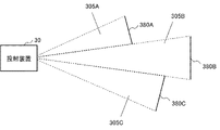
- FIG. 14 is a conceptual diagram for explaining an example of a projection surface 380 on which an image corresponding to projection light 305 modulated by multiple modulation regions 355 is displayed.
- An image corresponding to projection light 305A modulated by modulation region 355A is displayed on projection surface 380A.
- An image corresponding to projection light 305B modulated by modulation region 355B is displayed on projection surface 380B.
- An image corresponding to projection light 305C modulated by modulation region 355C is displayed on projection surface 380C.
- the image formed by the plurality of projection lights 305 modulated by the plurality of modulation regions 355 has the 0th order light removed by the light absorbing member 363 .
- Images formed by the plurality of projected lights 305 are displayed within a range that does not overlap each other.
- the images formed by the multiple projected lights 305 may overlap each other or may be displayed on spaced projection surfaces 380 .
- a projection surface 380 on which an image formed by a plurality of projection lights 305 is displayed is arbitrarily set.
- the controller 37 controls the light source 31 and the spatial light modulator 35 .
- the control unit 37 is implemented by a microcomputer including a processor and memory.
- the controller 37 has the same configuration as the controller 17 of the first embodiment.
- the control unit 37 drives the emitter 311 of the light source 31 in a state in which the synthesized image corresponding to the image to be displayed is set in each of the plurality of modulation regions 355 .
- the modulator 350 of the spatial light modulator 35 is irradiated with the parallel light 302 emitted from the light source 31 in accordance with the timing at which the composite image is set in each of the plurality of modulation regions 355 .
- the parallel light 302 irradiated to each of the multiple modulation regions 355 is modulated in each modulation region 355 .
- the projection light 305 modulated in each of the multiple modulation regions 355 is projected from the projection device 30 toward the projection surface 380 associated with the projection light 305 .
- FIG. 15 is a conceptual diagram for explaining an example of the focus position of the projection light 305 projected from the projection device 30.
- the projection device 30 can set different composite images in a plurality of modulation areas 355 set in the modulation section 350 of the spatial light modulator 35 .
- the focus position of the projection light 305 can be set for each of the plurality of modulation regions 355 by generating the composite image set in the plurality of modulation regions 355 using virtual lens images having focal lengths different from each other.
- the focus position of the projection light 305A is set to the projection surface 380A
- the focus position of the projection light 305B is set to the projection surface 380B
- the focus position of the projection light 305C is set to the projection surface 380C.
- the projection device of this embodiment includes a light source, a spatial light modulator, a zero-order light shield, and a controller.
- the light source, zero-order light blocker, and spatial light modulator constitute a projection section.
- the light source emits parallel light.
- the spatial light modulator has a modulation section that modulates the phase of parallel light emitted from the light source.
- the zero-order light shield includes a light absorbing member that shields zero-order light contained in projection light.
- the 0th-order light shield is arranged so that the light absorbing member is positioned on the optical path of the 0th-order light included in the projection light.
- the controller sets a plurality of modulation areas in the modulation section of the spatial light modulator.
- the controller sets a phase image corresponding to projection light projected in a plurality of projection directions in each of the plurality of modulation regions.
- the control unit controls the light source so that parallel light is emitted toward each of the plurality of modulation regions in which the phase image corresponding to the projection light is set.
- the projection device of this embodiment includes a 0th-order light remover that removes 0th-order light contained in projection light. Therefore, according to this embodiment, it is possible to project the projection light from which the zero-order light has been removed.
- the control unit generates a synthesized image obtained by synthesizing a phase image corresponding to an image displayed by projection light and a virtual lens image for condensing light at a desired focal length. It is set in each of a plurality of modulation regions set in the modulation section of the modulator. According to this aspect, the focus position of the projection light can be controlled by setting the synthesized image obtained by synthesizing the virtual lens image in the modulation section of the spatial light modulator and adjusting the projection angle of the projection light.
- control unit sets a synthesized image synthesized using virtual lens images with different focal lengths in each of a plurality of modulation regions set in the modulation unit of the spatial light modulator.
- an image can be displayed according to a plurality of focus positions by setting a composite image in which virtual lens images with different magnifications are synthesized for each of the plurality of modulation regions.
- the projection device of this embodiment can change the position of the light source, and can change the emission direction of the parallel light emitted from the light source.
- An example in which the projection apparatus of the first embodiment is configured such that the position of the light source can be changed will be described below.
- the projection apparatus of the second and third embodiments may be configured such that the position of the light source can be changed.
- FIG. 16 is a conceptual diagram showing an example of the configuration of the projection device 40 of this embodiment.
- Projection device 40 includes a plurality of light sources 41 , spatial light modulator 45 , controller 47 , and position change mechanism 48 .
- a plurality of light sources 41 , spatial light modulators 45 , and position changing mechanism 48 constitute projection section 400 .
- FIG. 16 is a lateral view of the internal configuration of the projection device 40. As shown in FIG. FIG. 16 illustrates lines indicating the trajectory of light. FIG. 16 is conceptual and does not accurately represent the positional relationship between each component, the traveling direction of light, and the like.
- the projection device 40 of this embodiment includes a plurality of light sources 41 as in other embodiments. Only one of the plurality of light sources 41 is illustrated in the drawings relating to the present embodiment.
- the light source 41 includes an emitter 411 and a collimator 412.
- the emitter 411 emits laser light 401 in a predetermined wavelength band under the control of the controller 47 .
- the collimator 412 converts the laser light 401 emitted from the emitter 411 into parallel light 402 .
- the emitter 411 has the same configuration as the emitter 111 of the first embodiment.
- the collimator 412 has the same configuration as the collimator 112 of the first embodiment.
- Laser light 401 emitted from emitter 411 is converted into parallel light 402 by collimator 412 and emitted from light source 41 .
- a parallel light 402 emitted from the light source 41 travels toward the modulation section 450 of the spatial light modulator 45 .
- the light source 41 is installed movably inside the projection device 40 .
- the position of the light source 41 is changed by the operation of the position changing mechanism 48 under the control of the controller 47 .
- the light source 41 is installed so that the angle of the optical axis of the parallel light 402 that irradiates the modulation section 450 of the spatial light modulator 45 can be adjusted.
- the light source 41 is movably arranged on a rail (not shown).
- the light source 41 is installed so as to move along an arc centered on the central portion of the modulation section 450 of the spatial light modulator 45 .
- a method of moving the light source 41 is not particularly limited.
- the spatial light modulator 45 has a modulating section 450 irradiated with parallel light 402 .
- the modulating section 450 is divided into a plurality of modulating regions associated with each of the plurality of light sources 41 .
- the spatial light modulator 45 has the same configuration as the spatial light modulator 15 of the first embodiment.
- Each of the plurality of modulation regions set in the modulation section 450 is irradiated with the parallel light 402 emitted from each of the plurality of light sources 41 .
- the parallel light 402 emitted by each of the plurality of light sources 41 is modulated by each of the plurality of modulation regions set in the modulation section 450 and projected as projection light 405 .
- the position changing mechanism 48 independently moves each of the plurality of light sources 41 under the control of the controller 47 .
- the position changing mechanism 48 is a mechanism for independently moving a plurality of light sources 41 installed so as to adjust the angle of the optical axis of the parallel light 402 that irradiates the modulation section 450 of the spatial light modulator 45.
- the position changing mechanism 48 is implemented by a mechanism that independently moves a plurality of light sources 41 that are movably arranged on rails (not shown).
- the position changing mechanism 48 is implemented by a mechanism that independently moves the plurality of light sources 41 that are installed so as to move on an arc centered on the central portion of the modulation section 450 of the spatial light modulator 45.
- the position changing mechanism 48 may be a mechanism that moves the plurality of light sources 41 in conjunction with each other.
- a method of moving the light source 41 is not particularly limited.
- the control unit 47 controls the light source 41, the spatial light modulator 45, and the position changing mechanism 48.
- the control unit 47 is implemented by a microcomputer including a processor and memory.
- the controller 47 has the same configuration as the controller 17 of the first embodiment except for controlling the position changing mechanism 48 .
- the control unit 47 drives the emitter 411 of the light source 41 while the phase image corresponding to the displayed image is set in each of the plurality of modulation regions assigned to the modulation unit 450 .
- the modulator 450 of the spatial light modulator 45 is irradiated with the parallel light 402 emitted from the light source 41 in accordance with the timing at which the phase images are set in each of the plurality of modulation regions.
- the parallel light 402 applied to each of the plurality of modulation regions is modulated in each modulation region.
- the projection light 405 modulated in each of the multiple modulation regions is projected from the projection device 40 toward the projection surface associated with the projection light 405 .
- the control unit 47 controls the position changing mechanism 48 to change the position of the light source 41 .
- the control unit 47 changes the projection direction of the projection light 405 by controlling the position changing mechanism 48 so as to change the incident angle of the parallel light 402 with respect to the modulation unit 450 of the spatial light modulator 45 .
- the control unit 47 changes the projection direction of the projection light 405 according to instructions from an external system (not shown) that manages the projection device 40 .
- the control unit 47 changes the projection direction of the projection light 405 based on preset conditions.
- the timing of changing the projection direction of the projection light 405 can be set arbitrarily.
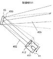
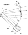
- FIGS. 17A and 17B are conceptual diagrams for explaining an example of changing the projection direction of the projection light 405 by changing the position of the light source 41.
- FIG. in the control example V1 of FIG. 17A the light source 41 is moved toward the lower left direction of the drawing. As a result, the projection direction of the projection light 405 is changed toward the upper right direction in the drawing.
- control example V2 of FIG. 7B the light source 41 is moved toward the upper right direction of the drawing. As a result, the projection direction of the projection light 405 is changed toward the lower right direction in the drawing.
- the control section 47 may be configured to independently control the positions of a plurality of light sources 41 . Further, the control unit 47 may be configured to interlock and control the positions of the plurality of light sources 41 .
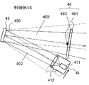
- FIGS. 18A and 18B are conceptual diagrams for explaining another example of changing the projection direction of the projection light 405 by changing the position of the light source 41.
- FIG. In the example of FIGS. 18A and 18B, a 0th-order light remover 46 for blocking 0th-order light is arranged on the optical path of projection light 405 .
- the zero-order light remover 46 has the same configuration as the zero-order light remover 36 of the third embodiment.
- the zero-order light remover 46 includes a holding member 461 and a light absorbing member 463 .
- the zero-order light remover 46 is installed movably like the light source 41 .
- the light absorbing member 463 is arranged on the optical path of the zero-order light included in the projection light 405 by the holding member 461 .
- the holding member 461 is installed movably inside the projection device 40 .
- the position of the holding member 461 is changed in conjunction with the movement of the light source 41 by the operation of the position changing mechanism 48 under the control of the controller 47 .
- the light source 41 and the zero-order light remover 46 are connected by a link mechanism (not shown).
- control example V3 of FIG. 18A the light source 41 is moved toward the lower left direction of the drawing. In conjunction with the movement of the light source 41, the zero-order light remover 46 is moved upward in the drawing. As a result, the projected light 405 changes its projection direction toward the upper right in the drawing, and the 0th order light is removed by the 0th order light remover 46 .
- control example V4 of FIG. 18B the light source 41 is moved toward the upper right direction of the drawing. In conjunction with the movement of the light source 41, the zero-order light remover 46 is moved downward in the drawing. As a result, the projected light 405 changes its projection direction toward the lower right direction in the drawing, and the 0th order light is removed by the 0th order light remover 46 .
- 18A and 18B show only one 0th-order light remover 46, the 0th-order light remover 46 is provided for each of a plurality of modulation regions set in the modulation section 450 of the spatial light modulator 45. is installed in
- the projection device of this embodiment includes a light source, a position changing mechanism, a spatial light modulator, and a controller.
- the light source, repositioning mechanism, and spatial light modulator constitute a projection section.
- the light source emits parallel light.
- a position changing mechanism changes the position of the light source.
- the spatial light modulator has a modulation section that modulates the phase of parallel light emitted from the light source.
- the controller controls the position changing mechanism to change the projection direction of the projection light.
- the controller sets a plurality of modulation areas in the modulation section of the spatial light modulator.
- the controller sets a phase image corresponding to projection light projected in a plurality of projection directions in each of the plurality of modulation regions.
- the control unit controls the light source so that parallel light is emitted toward each of the plurality of modulation regions in which the phase image corresponding to the projection light is set.
- the projection device of this embodiment includes a position changing mechanism that changes the position of the light source. Therefore, according to this embodiment, by changing the position of the light source, the optical axis of the parallel light emitted from the light source can be changed, and the projection direction of the projection light can be controlled. According to the present embodiment, the projection direction of projection light can be changed more greatly than when the projection direction of projection light is controlled by changing the phase image displayed on the display section of the spatial light modulator.
- the projection device of this embodiment has a configuration in which a light receiver for receiving light is added.
- a light receiver is added to the projection device of the first embodiment will be described below.
- a light receiver may be added to the projection apparatus of the second to fourth embodiments.
- FIG. 19 is a conceptual diagram showing an example of the configuration of the projection device 50 of this embodiment.
- Projection device 50 includes a plurality of light sources 51 , spatial light modulator 55 , controller 57 , and light receiver 59 .
- a plurality of light sources 51 and spatial light modulators 55 constitute a projection section 500 .
- FIG. 19 is a lateral view of the internal configuration of the projection device 50. As shown in FIG. FIG. 19 illustrates lines indicating the trajectory of light.
- FIG. 19 is conceptual, and does not accurately represent the positional relationship between each component, the traveling direction of light, and the like. Although only a single light source 51 is shown in FIG. 19, the projection device 50 of this embodiment is assumed to have a plurality of light sources 51 as in the other embodiments.
- the light source 51 includes an emitter 511 and a collimator 512.
- the emitter 511 emits laser light 501 in a predetermined wavelength band under the control of the controller 57 .
- the collimator 512 converts the laser light 501 emitted from the emitter 511 into parallel light 502 .
- the emitter 511 has the same configuration as the emitter 111 of the first embodiment.
- the collimator 512 has the same configuration as the collimator 112 of the first embodiment.
- Laser light 501 emitted from emitter 511 is converted into parallel light 502 by collimator 512 and emitted from light source 51 .
- a parallel light 502 emitted from the light source 51 travels toward the modulation section 550 of the spatial light modulator 55 .
- the spatial light modulator 55 has a modulating section 550 irradiated with parallel light 502 .
- the modulating section 550 is divided into a plurality of modulating regions associated with each of the plurality of light sources 51 .
- the spatial light modulator 55 has the same configuration as the spatial light modulator 15 of the first embodiment.
- Each of the plurality of modulation regions set in the modulation section 550 is irradiated with parallel light 502 emitted from each of the plurality of light sources 51 .
- the parallel light 502 emitted by each of the plurality of light sources 51 is modulated by each of the plurality of modulation regions set in the modulation section 550 and projected as projection light 505 .
- the light receiver 59 has at least one light receiving element that receives light.
- the light receiver 59 may have a plurality of light receiving elements.
- the light-receiving surface of the light receiver 59 faces an object to be communicated or distance-measured.
- the light receiving surface of the light receiver 59 is oriented in the same direction as the projection direction of the projected light 505 .
- a light receiving element included in the light receiver 59 receives light in the wavelength band to be received.
- the light receiving element receives light in the visible region.
- the light receiving element receives light in the infrared region.
- the light-receiving element receives, for example, light with a wavelength in the 1.5 ⁇ m (micrometer) band.
- the wavelength band of light received by the light receiving element is not limited to the 1.5 ⁇ m band.
- the wavelength band of light received by the light receiving element can be arbitrarily set according to the wavelength of the light to be received.
- the wavelength band of light received by the light receiving element may be set to, for example, 0.8 ⁇ m band, 1.55 ⁇ m band, or 2.2 ⁇ m band.
- the wavelength band of light received by the light receiving element may be, for example, the 0.8 to 1 ⁇ m band.
- the shorter the wavelength band of light the smaller the absorption by moisture in the atmosphere, which is advantageous for light reception during rainfall.
- the light receiving element cannot read the light when it is saturated with intense sunlight. Therefore, a color filter for selectively passing the light in the wavelength band to be received may be provided in the preceding stage of the light receiving element.
- the light receiving element converts the received light into an electrical signal.
- the light receiving element can be realized by an element such as a photodiode or a phototransistor.
- the light receiving element is realized by an avalanche photodiode.
- a light-receiving element realized by an avalanche photodiode can handle high-speed communication.
- the light-receiving element may be realized by an element other than a photodiode, a phototransistor, or an avalanche photodiode as long as it can convert light into an electric signal.
- the light receiving area of the light receiving element included in the light receiver 59 is as small as possible.
- the light receiving area of the light receiving element has a diameter of about 0.1 to 0.3 mm (millimeters).
- a condenser lens may be provided for condensing the light on the light receiving area of the light receiving element.
- the condensing lens is configured to efficiently guide light arriving from any direction to the light receiving area of the light receiving element.
- a controller 57 controls the light source 51 and the spatial light modulator 55 .
- the controller 57 receives an electrical signal based on the light received by the light receiver 59 .
- the control unit 57 is implemented by a microcomputer including a processor and memory.
- the controller 57 has the same configuration as the controller 17 of the first embodiment except that it receives an electrical signal from the photodetector 59 .
- the control unit 57 drives the emitter 511 of the light source 51 with the phase image corresponding to the displayed image set in each of the plurality of modulation regions assigned to the modulation unit 550 .
- the modulator 550 of the spatial light modulator 55 is irradiated with the parallel light 502 emitted from the light source 51 in accordance with the timing at which the phase images are set in each of the plurality of modulation regions.
- the parallel light 502 applied to each of the plurality of modulation regions is modulated in each modulation region.
- the projection light 505 modulated in each of the multiple modulation regions is projected from the projection device 50 toward the projection surface associated with the projection light 505 .
- the control unit 57 receives a signal based on the light received by the light receiver 59 .
- the controller 37 sets the projection direction of the projection light 505 according to a signal based on the light received by the light receiver 59 .
- the controller 57 uses a signal based on the light received by the light receiver 59 to measure the distance to the object.
- the controller 57 decodes the spatial light signal received by the light receiver 59 .
- the controller 57 outputs the decoded signal to another system or device (not shown).
- control unit 57 measures the distance to the projection target according to the time it takes for the light projected from the projection device 50 to return after being reflected by the projection target.
- the control unit 57 may measure the distance to the projection target based on the image data captured by the camera using the principle of triangulation. Also, the distance between the projection device 50 and the projection target may be measured by an external system (not shown).
- the projection device of this embodiment includes a light source, a spatial light modulator, a light receiver, and a controller.
- the light source, repositioning mechanism, and spatial light modulator constitute a projection section.
- the light source emits parallel light.
- the spatial light modulator has a modulation section that modulates the phase of parallel light emitted from the light source.
- the controller controls the position changing mechanism to change the projection direction of the projection light.
- the light receiver receives light coming from the projection direction of the projection light.
- the controller sets a plurality of modulation areas in the modulation section of the spatial light modulator.
- the controller sets a phase image corresponding to projection light projected in a plurality of projection directions in each of the plurality of modulation regions.
- the control unit controls the light source so that parallel light is emitted toward each of the plurality of modulation regions in which the phase image corresponding to the projection light is set.
- the projection device of this embodiment can receive light arriving from the projection direction of the projection light with the light receiver. Therefore, according to this embodiment, it is possible to realize optical space communication for transmitting and receiving spatial optical signals.
- FIG. 20 is a block diagram showing an example of the configuration of the projection device 60 of this embodiment.
- Projection device 60 includes light source 61 , spatial light modulator 65 , and controller 67 .
- Light source 61 and spatial light modulator 65 constitute projection section 600 .
- FIG. 20 is a lateral view of the internal configuration of the projection device 60. As shown in FIG. FIG. 20 illustrates lines indicating the trajectory of light.
- FIG. 20 is conceptual, and does not accurately represent the positional relationship between each component, the traveling direction of light, and the like.
- the light source 61 emits parallel light.
- the spatial light modulator 65 has a modulating section 650 that modulates the phase of the parallel light 602 emitted from the light source 61 .
- the control section 67 sets a plurality of modulation areas in the modulation section 650 of the spatial light modulator 65 .
- the control unit 67 sets a phase image corresponding to the projection light 605 projected in a plurality of projection directions in each of the plurality of modulation regions.
- the control unit 67 controls the light source 61 so that the parallel light 602 is emitted toward each of the plurality of modulation regions in which the phase images corresponding to the projection light 605 are set.
- the projection apparatus of this embodiment projects the light in the Fraunhofer region modulated by the modulation unit of the spatial light modulator without using a projection optical system. Therefore, according to this embodiment, the projection optical system is omitted, and a compact projection apparatus can be realized.
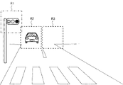
- FIG. 21 is a conceptual diagram for explaining application example 1 of each embodiment.
- FIG. 21 shows an example in which projection light is projected forward from an automobile equipped with a projection device.
- roads drive on the left side, and light-emitting surfaces of traffic signals and illumination of street lamps are placed above the left side of the road.
- vehicles heading in the same direction run on the left side of the road, and vehicles heading in the opposite direction run on the right side of the road.
- an area R1 that can include the light emitting surface of the traffic signal, an area R2 that can include vehicles traveling in the same direction, and an area R3 that can include vehicles traveling in the opposite direction are set.
- the projection device can independently change the projection directions of the plurality of light sources. Therefore, the projection device can project different projection light toward each of the regions R1, R2, and R3. For example, if a traffic signal or a streetlight is provided with a communication device, the projection device can perform spatial optical communication with the communication device while the traffic signal or the streetlight is within the range of region R1. can. For example, the projection device may measure the inter-vehicle distance to a vehicle traveling ahead. For example, the projection device may individually communicate with communication targets located within regions R1-R3.
- the communication device may individually measure the distances to distance targets located within the regions R1 to R3.
- the projection device communicates with a communication target located within any one of the areas R1 to R3, and measures the distance to the distance measurement target located within any of the areas R1 to R3.
- the projection device may measure the distance to a vehicle located within the region R2, and switch to communicate with the vehicle according to the distance to the vehicle.
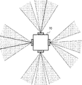
- FIG. 22 is a conceptual diagram for explaining application example 2 (projection device 70) of each embodiment.
- FIG. 22 is a view looking down on the projection device 70 from an upper viewpoint.
- the projection device 70 includes at least two sets of projection units that project projection light in different projection directions.
- the projection device 70 includes four sets of projection units included in the projection device of each embodiment.
- the four sets of projection units included in the projection device 70 are combined so as to project projection light in different projection directions.
- each projection unit is arranged with the projection direction shifted by 90 degrees. It is assumed that the modulation section of the spatial light modulator included in each projection section is divided into three modulation regions. In this application example, it is assumed that the projection angle of the projection light modulated by each modulation area is set to 20 degrees.
- each of the projection lights projected toward the left, upper, right, and lower four directions is composed of projection lights modulated in three modulation regions.
- the projection light projected toward the left side is an example in which the projection light projected at a projection angle of 20 degrees is projected without gaps.
- the total projection angle of the projection light projected toward the left side is 60 degrees.
- Projection light projected upward is an example in which projection light projected at a projection angle of 20 degrees is projected at unbalanced intervals.
- the projection light projected toward the right side is an example in which the projection light projected at a projection angle of 20 degrees is projected with equal intervals.
- the total projection angle of the projection light projected toward the left side is set to 90 degrees.
- the projection light projected downward is an example in which the projection light projected at a projection angle of 20 degrees is projected with an equal interval.
- the total projection angle of the projection light projected downward is arbitrarily set.
- projection light can be projected toward 360 degrees around the projection device 70 .
- the projection direction and the projection angle of the projection light projected from the four sets of projection units may be fixed, or the projection direction and the projection angle may be changed.
- Projection device 70 may be configured to include the number of projection units according to the application.
- the projection device 70 may be configured by combining two sets of projection units.
- the projection device 70 may be configured by combining a plurality of projection devices.
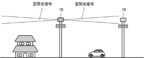
- FIG. 23 is a conceptual diagram for explaining an arrangement example of the projection device 70 of this application example.
- the example of FIG. 23 is an example in which the projection device 70 is arranged above a utility pole.
- the projection device 70 may have a function of wireless communication. Since there are few obstacles on the upper part of the utility pole, it is suitable for free-space optical communication for transmitting and receiving spatial optical signals.
- a spatial optical communication network can be constructed in which spatial optical signals are transmitted and received between the projection devices 70 .
- the projection device 70 located in the middle of the network relays the spatial optical signal transmitted from one projection device 70 to another projection device 70. It may be configured as a repeater.
- the projection device of this application example includes a plurality of projection units each including at least one light source and a spatial light modulator.
- the plurality of projection units are arranged with the projection directions facing in mutually different directions.
- the projection light can be projected over a wide range centered on the projection device.
- communication using a spatial light signal becomes possible between projection devices installed on a plurality of utility poles.
- wireless communication may be performed between the wireless device and the projection device installed in a car, house, or the like.
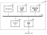
- control device 90 of FIG. 24 the hardware configuration for executing the processing of the control unit according to each embodiment of the present disclosure will be described by taking the control device 90 of FIG. 24 as an example.
- the control device 90 is implemented in the form of a microcomputer.
- the control device 90 of FIG. 24 is a configuration example for executing the processing of the control unit of each embodiment, and does not limit the scope of the present disclosure.
- the control device 90 includes a processor 91, a main storage device 92, an auxiliary storage device 93, an input/output interface 95, and a communication interface 96.
- the interface is abbreviated as I/F (Interface).
- Processor 91 , main storage device 92 , auxiliary storage device 93 , input/output interface 95 , and communication interface 96 are connected to each other via bus 98 so as to enable data communication.
- the processor 91 , the main storage device 92 , the auxiliary storage device 93 and the input/output interface 95 are connected to a network such as the Internet or an intranet via a communication interface 96 .
- the processor 91 loads the program stored in the auxiliary storage device 93 or the like into the main storage device 92 .
- the processor 91 executes programs developed in the main memory device 92 .
- a configuration using a software program installed in the control device 90 may be used.
- the processor 91 executes processing by the control unit according to this embodiment.
- the main storage device 92 has an area in which programs are expanded.
- a program stored in the auxiliary storage device 93 or the like is developed in the main storage device 92 by the processor 91 .
- the main memory device 92 is realized by a volatile memory such as a DRAM (Dynamic Random Access Memory). Further, as the main storage device 92, a non-volatile memory such as MRAM (Magnetoresistive Random Access Memory) may be configured/added.
- the auxiliary storage device 93 stores various data such as programs.
- the auxiliary storage device 93 is implemented by a local disk such as a hard disk or flash memory. It should be noted that it is possible to store various data in the main storage device 92 and omit the auxiliary storage device 93 .
- the input/output interface 95 is an interface for connecting the control device 90 and peripheral devices based on standards and specifications.
- a communication interface 96 is an interface for connecting to an external system or device through a network such as the Internet or an intranet based on standards and specifications.
- the input/output interface 95 and the communication interface 96 may be shared as an interface for connecting with external devices.
- Input devices such as a keyboard, mouse, and touch panel may be connected to the control device 90 as necessary. These input devices are used to enter information and settings.
- touch panel When a touch panel is used as an input device, the display screen of the display device may also serve as an interface of the input device. Data communication between the processor 91 and the input device may be mediated by the input/output interface 95 .
- control device 90 may be equipped with a display device for displaying information.
- control device 90 is preferably provided with a display control device (not shown) for controlling the display of the display device.
- the display device may be connected to the control device 90 via the input/output interface 95 .
- control device 90 may be equipped with a drive device. Between the processor 91 and a recording medium (program recording medium), the drive device mediates reading of data and programs from the recording medium, writing of processing results of the control device 90 to the recording medium, and the like.
- the drive device may be connected to the control device 90 via the input/output interface 95 .
- the above is an example of the hardware configuration for enabling the control unit according to each embodiment of the present invention.
- the hardware configuration of FIG. 24 is an example of the hardware configuration for executing arithmetic processing of the control unit according to each embodiment, and does not limit the scope of the present invention.
- the scope of the present invention also includes a program that causes a computer to execute processing related to the control unit according to each embodiment. Further, the scope of the present invention also includes a program recording medium on which the program according to each embodiment is recorded.
- the recording medium can be implemented as an optical recording medium such as a CD (Compact Disc) or a DVD (Digital Versatile Disc).
- the recording medium may be implemented by a semiconductor recording medium such as a USB (Universal Serial Bus) memory or an SD (Secure Digital) card. Also, the recording medium may be realized by a magnetic recording medium such as a flexible disk, or other recording medium. When a program executed by a processor is recorded on a recording medium, the recording medium corresponds to a program recording medium.
- a semiconductor recording medium such as a USB (Universal Serial Bus) memory or an SD (Secure Digital) card.
- SD Secure Digital
- the recording medium may be realized by a magnetic recording medium such as a flexible disk, or other recording medium.
- the constituent elements of the control unit of each embodiment may be combined arbitrarily. Also, the constituent elements of the control unit of each embodiment may be realized by software or by a circuit.
Landscapes
- Physics & Mathematics (AREA)
- General Physics & Mathematics (AREA)
- Optics & Photonics (AREA)
- Nonlinear Science (AREA)
- Electromagnetism (AREA)
- Engineering & Computer Science (AREA)
- Computer Networks & Wireless Communication (AREA)
- Signal Processing (AREA)
- Liquid Crystal (AREA)
- Projection Apparatus (AREA)
Priority Applications (2)
| Application Number | Priority Date | Filing Date | Title |
|---|---|---|---|
| JP2023508761A JP7613556B2 (ja) | 2021-03-22 | 2022-02-10 | 投射装置および投射方法 |
| US18/281,987 US20240168363A1 (en) | 2021-03-22 | 2022-02-10 | Projection device and projection method |
Applications Claiming Priority (2)
| Application Number | Priority Date | Filing Date | Title |
|---|---|---|---|
| JP2021-047565 | 2021-03-22 | ||
| JP2021047565 | 2021-03-22 |
Publications (1)
| Publication Number | Publication Date |
|---|---|
| WO2022201941A1 true WO2022201941A1 (ja) | 2022-09-29 |
Family
ID=83395562
Family Applications (1)
| Application Number | Title | Priority Date | Filing Date |
|---|---|---|---|
| PCT/JP2022/005239 Ceased WO2022201941A1 (ja) | 2021-03-22 | 2022-02-10 | 投射装置および投射方法 |
Country Status (3)
| Country | Link |
|---|---|
| US (1) | US20240168363A1 (https=) |
| JP (1) | JP7613556B2 (https=) |
| WO (1) | WO2022201941A1 (https=) |
Cited By (1)
| Publication number | Priority date | Publication date | Assignee | Title |
|---|---|---|---|---|
| JP2023032469A (ja) * | 2021-08-27 | 2023-03-09 | Necプラットフォームズ株式会社 | 投射装置、投射制御方法、およびプログラム |
Citations (2)
| Publication number | Priority date | Publication date | Assignee | Title |
|---|---|---|---|---|
| US20080056723A1 (en) * | 2005-08-09 | 2008-03-06 | Randy Clinton Giles | Multiple access free space laser communication method and apparatus |
| WO2018223646A1 (en) * | 2017-06-08 | 2018-12-13 | Boe Technology Group Co., Ltd. | A dual-image projection apparatus, a head-up display apparatus, and a vehicle vision auxiliary system |
-
2022
- 2022-02-10 JP JP2023508761A patent/JP7613556B2/ja active Active
- 2022-02-10 US US18/281,987 patent/US20240168363A1/en active Pending
- 2022-02-10 WO PCT/JP2022/005239 patent/WO2022201941A1/ja not_active Ceased
Patent Citations (2)
| Publication number | Priority date | Publication date | Assignee | Title |
|---|---|---|---|---|
| US20080056723A1 (en) * | 2005-08-09 | 2008-03-06 | Randy Clinton Giles | Multiple access free space laser communication method and apparatus |
| WO2018223646A1 (en) * | 2017-06-08 | 2018-12-13 | Boe Technology Group Co., Ltd. | A dual-image projection apparatus, a head-up display apparatus, and a vehicle vision auxiliary system |
Cited By (2)
| Publication number | Priority date | Publication date | Assignee | Title |
|---|---|---|---|---|
| JP2023032469A (ja) * | 2021-08-27 | 2023-03-09 | Necプラットフォームズ株式会社 | 投射装置、投射制御方法、およびプログラム |
| JP7623249B2 (ja) | 2021-08-27 | 2025-01-28 | Necプラットフォームズ株式会社 | 投射装置、投射制御方法、およびプログラム |
Also Published As
| Publication number | Publication date |
|---|---|
| JPWO2022201941A1 (https=) | 2022-09-29 |
| US20240168363A1 (en) | 2024-05-23 |
| JP7613556B2 (ja) | 2025-01-15 |
Similar Documents
| Publication | Publication Date | Title |
|---|---|---|
| JP5858185B2 (ja) | 光投射装置および車載用前照灯 | |
| JP7613556B2 (ja) | 投射装置および投射方法 | |
| JP7613557B2 (ja) | 投射装置および投射方法 | |
| US20240348754A1 (en) | Projection device, projection control method, and recording medium | |
| US20240283537A1 (en) | Transmitter, transmission device, communication device, and communication system | |
| JP7589824B2 (ja) | 投射装置および通信装置 | |
| CN211123505U (zh) | 大幅面可控偏振图案生成装置 | |
| WO2023026460A1 (ja) | 受信装置および通信装置 | |
| US20240056192A1 (en) | Transmitter, transmission device, communication device, and communication system | |
| US20240027741A1 (en) | Light receiving device, reception device, communication device, and communication system | |
| US20240171286A1 (en) | Light reception device, reception device, and communication device | |
| US20250279833A1 (en) | Transmitter, transmission device, communication device, and communication system | |
| JP7622858B2 (ja) | 送光装置、通信装置、制御方法、およびプログラム | |
| US20250300736A1 (en) | Transmission device and communication device | |
| US20240056185A1 (en) | Transmission device, communication device, and communication system | |
| US20240353745A1 (en) | Projection device, projection control method, and recording medium | |
| JP7574943B2 (ja) | 通信制御装置、通信装置、通信制御方法、およびプログラム | |
| US20240129037A1 (en) | Transmitter, transmission device, communication device, and communication system | |
| US20230418003A1 (en) | Receiver, reception device, communication device, and communication system | |
| US20240129036A1 (en) | Transmitter, transmission device, communication device, and communication system | |
| KR20120055893A (ko) | 레이저를 이용한 패턴형성장치 | |
| JP2024117218A (ja) | 受信装置、通信装置、および通信システム | |
| JP2024131328A (ja) | 送信器、送信装置、通信装置、および通信システム | |
| WO2023042304A1 (ja) | 受信制御装置、受信制御方法、および記録媒体 | |
| WO2023026462A1 (ja) | 送光装置および通信装置 |
Legal Events
| Date | Code | Title | Description |
|---|---|---|---|
| 121 | Ep: the epo has been informed by wipo that ep was designated in this application |
Ref document number: 22774742 Country of ref document: EP Kind code of ref document: A1 |
|
| WWE | Wipo information: entry into national phase |
Ref document number: 2023508761 Country of ref document: JP |
|
| WWE | Wipo information: entry into national phase |
Ref document number: 18281987 Country of ref document: US |
|
| NENP | Non-entry into the national phase |
Ref country code: DE |
|
| 122 | Ep: pct application non-entry in european phase |
Ref document number: 22774742 Country of ref document: EP Kind code of ref document: A1 |