WO2022201877A1 - Lens barrel - Google Patents
Lens barrel Download PDFInfo
- Publication number
- WO2022201877A1 WO2022201877A1 PCT/JP2022/003798 JP2022003798W WO2022201877A1 WO 2022201877 A1 WO2022201877 A1 WO 2022201877A1 JP 2022003798 W JP2022003798 W JP 2022003798W WO 2022201877 A1 WO2022201877 A1 WO 2022201877A1
- Authority
- WO
- WIPO (PCT)
- Prior art keywords
- lens
- fixed
- holding frame
- cam
- moving
- Prior art date
Links
- 230000003287 optical effect Effects 0.000 claims abstract description 99
- 230000007246 mechanism Effects 0.000 claims abstract description 60
- 230000002093 peripheral effect Effects 0.000 claims abstract description 59
- 230000005540 biological transmission Effects 0.000 claims abstract description 14
- 238000003384 imaging method Methods 0.000 claims description 10
- 230000000149 penetrating effect Effects 0.000 claims description 6
- 238000011156 evaluation Methods 0.000 description 9
- 230000004075 alteration Effects 0.000 description 3
- 238000010586 diagram Methods 0.000 description 3
- 230000009471 action Effects 0.000 description 2
- 230000008859 change Effects 0.000 description 2
- 239000000428 dust Substances 0.000 description 2
- 230000006866 deterioration Effects 0.000 description 1
- 230000000694 effects Effects 0.000 description 1
- 229920001971 elastomer Polymers 0.000 description 1
- 239000000806 elastomer Substances 0.000 description 1
- 238000003780 insertion Methods 0.000 description 1
- 230000037431 insertion Effects 0.000 description 1
- 238000007689 inspection Methods 0.000 description 1
- 238000004519 manufacturing process Methods 0.000 description 1
- 238000000034 method Methods 0.000 description 1
- 230000004048 modification Effects 0.000 description 1
- 238000012986 modification Methods 0.000 description 1
- 230000035515 penetration Effects 0.000 description 1
- 238000007789 sealing Methods 0.000 description 1
Images


Classifications
-
- G—PHYSICS
- G02—OPTICS
- G02B—OPTICAL ELEMENTS, SYSTEMS OR APPARATUS
- G02B7/00—Mountings, adjusting means, or light-tight connections, for optical elements
- G02B7/02—Mountings, adjusting means, or light-tight connections, for optical elements for lenses
- G02B7/04—Mountings, adjusting means, or light-tight connections, for optical elements for lenses with mechanism for focusing or varying magnification
- G02B7/10—Mountings, adjusting means, or light-tight connections, for optical elements for lenses with mechanism for focusing or varying magnification by relative axial movement of several lenses, e.g. of varifocal objective lens
- G02B7/102—Mountings, adjusting means, or light-tight connections, for optical elements for lenses with mechanism for focusing or varying magnification by relative axial movement of several lenses, e.g. of varifocal objective lens controlled by a microcomputer
-
- G—PHYSICS
- G02—OPTICS
- G02B—OPTICAL ELEMENTS, SYSTEMS OR APPARATUS
- G02B7/00—Mountings, adjusting means, or light-tight connections, for optical elements
- G02B7/02—Mountings, adjusting means, or light-tight connections, for optical elements for lenses
- G02B7/04—Mountings, adjusting means, or light-tight connections, for optical elements for lenses with mechanism for focusing or varying magnification
- G02B7/10—Mountings, adjusting means, or light-tight connections, for optical elements for lenses with mechanism for focusing or varying magnification by relative axial movement of several lenses, e.g. of varifocal objective lens
-
- G—PHYSICS
- G03—PHOTOGRAPHY; CINEMATOGRAPHY; ANALOGOUS TECHNIQUES USING WAVES OTHER THAN OPTICAL WAVES; ELECTROGRAPHY; HOLOGRAPHY
- G03B—APPARATUS OR ARRANGEMENTS FOR TAKING PHOTOGRAPHS OR FOR PROJECTING OR VIEWING THEM; APPARATUS OR ARRANGEMENTS EMPLOYING ANALOGOUS TECHNIQUES USING WAVES OTHER THAN OPTICAL WAVES; ACCESSORIES THEREFOR
- G03B17/00—Details of cameras or camera bodies; Accessories therefor
-
- H—ELECTRICITY
- H04—ELECTRIC COMMUNICATION TECHNIQUE
- H04N—PICTORIAL COMMUNICATION, e.g. TELEVISION
- H04N23/00—Cameras or camera modules comprising electronic image sensors; Control thereof
- H04N23/50—Constructional details
- H04N23/55—Optical parts specially adapted for electronic image sensors; Mounting thereof
Definitions
- the present invention relates to a lens barrel.
- Patent Document 1 discloses a technique of adjusting the eccentricity of the first lens (26A) constituting the rear fixed focus lens (26) by rotating a rotating member (54) having a gear (54A). ing.
- the lens is rotated at a fixed focus, and eccentricity can be adjusted.
- the lens interval cannot be adjusted.
- a predetermined portion of the lens frame that holds the lens Adjustment members such as shims and washers are arranged between the lens frames that hold the respective lenses. By changing the thickness and the number of adjustment members as necessary, the lens interval is adjusted to a desired dimension.
- the lens adjustment interval is limited by the lineup of shims and washers, making fine adjustment of the lens interval difficult.
- it is necessary to replace the shims and washers that have already been incorporated when adjusting the lens interval it is necessary to disassemble the lens barrel for the replacement.
- the number of man-hours is increased, and there is a risk that dust may enter the interior of the lens barrel or the lens may be damaged when the lens barrel is disassembled.
- after adjusting the lens spacing it is necessary to reassemble the lens barrel in order to evaluate its performance.
- the present invention has been made in view of such problems, and an object of the present invention is to provide a lens barrel capable of finely adjusting the lens spacing of movable zoom lens groups from the outside. Let's try.
- a lens barrel that internally holds a lens system having a plurality of lens groups each having one or more optical elements, the lens barrel along the optical axis direction a fixed barrel formed with a guide groove into which the cam follower enters; a cam barrel rotatably provided with respect to the fixed barrel and having a cam groove in which the cam follower enters and is inclined with respect to the optical axis direction; and a lens group
- At least one of the moving lens groups constitutes a moving mechanism unit that changes the focal length or the focus position by moving at least one lens group as a moving lens group in the optical axis direction, and an adjustment moving lens group that is at least one moving lens group.
- an adjusting mechanism for adjusting the position of one optical element in the optical axis direction the moving mechanism having a cam follower attached thereto, and adjusting the optical axis along with the relative rotation of the cam barrel with respect to the fixed barrel; and a movable lens holding frame that holds at least a part of the optical element of the movable lens group.
- a drive transmission portion provided on the outer peripheral side of the linear movable lens holding frame, an inner peripheral engaging portion formed on the inner peripheral surface of the movable holding frame, and an inner peripheral engaging portion on the outer peripheral surface of the movable lens holding frame. It is formed in an engaged state, and rotates with respect to the inner peripheral engagement portion to move the movable lens holding frame in the optical axis direction when an external force is transmitted in the rotational direction through the drive transmission portion.
- a lens barrel is provided comprising: a buttress;
- the adjustment moving lens group has at least a first adjustment moving lens subgroup and a second adjustment moving lens subgroup, and a first adjustment moving lens subgroup.
- the groups are held in a moving holding frame and the second adjustment moving lens subgroup is held in a movable lens holding frame.
- the position fixing mechanism includes a screw hole penetrating the cylindrical portion of the movable holding frame, a fixing screw screwed into the screw hole, a fixing screw passing through the fixing barrel, and a screw hole and the screw hole.
- the fixed-side through-hole and the cam barrel are passed through and the fixing screw is inserted. and a cam-side through-hole existing on the same straight line as the hole.
- the fixed-side through hole is provided at a position that does not interfere with the fixed-side hole portion, and the cam-side through hole is preferably provided at a position where they do not interfere.
- the movable holding frame is provided with a positioning engaging portion for positioning an adjusting jig to be inserted from the outside. preferable.
- an elastic member is arranged in the gap between the movable holding frame and the movable lens holding frame to urge both members in a direction to separate them from each other. preferably.
- the other aspect of the present invention further includes a plurality of fixed side holes and cam side holes provided at positions separated from each other in the optical axis direction.
- Another aspect of the present invention is preferably an imaging apparatus including the lens barrel according to the invention described above and an imaging device arranged on the telephoto side of the lens barrel.
- an image display device having a lens barrel and an image display element arranged on the telephoto side of the lens barrel.
- the present invention it is possible to provide a lens barrel capable of finely adjusting the lens spacing of the movable zoom lens group from the outside.
- FIG. 4 is a cross-sectional view of the lens barrel cut along the optical axis according to the embodiment of the present invention, showing a state in which the third lens group (zoom lens group) is positioned on the wide-angle side (wide-angle side); is. 2 is a diagram showing a state in which a third lens group (zoom lens group) shown in FIG. 1 is positioned on the telephoto side (telephoto side); FIG. 2 is a partial cross-sectional view showing an enlarged part of a zoom mechanism section of the lens barrel shown in FIG. 1; FIG. 1. It is a figure which shows the positional relationship of the guide groove and cam groove with which the zoom mechanism part of the lens-barrel shown in FIG.
- FIG. 1 is provided, (A) is the figure which expanded the zoom mechanism part into planar shape, (B) is a zoom mechanism. It is a cross-sectional view of the part. 2 is a perspective view showing a state in which the vicinity of a fixed side hole portion of the lens barrel shown in FIG. 1 is cut along a plane perpendicular to the optical axis; FIG. FIG. 2 is a plan view of the zoom mechanism of the lens barrel shown in FIG. 1 and shows a state in which a lens held via a moving frame is positioned on the telephoto side (telephoto side); FIG. 2 is a plan view of the zoom mechanism portion of the lens barrel shown in FIG. 1 and shows a state in which a lens held via a moving frame is positioned on the wide angle side (wide side).
- FIG. 3 is an exploded perspective view showing the configuration of an adjusting jig used in the present embodiment;
- a lens barrel according to one embodiment of the present invention will be described below with reference to the drawings.
- the object side is the front side (X1 side), and the side where it is attached to the camera body (telephoto side). is the rear side (X2 side).
- a direction perpendicular to the optical axis direction (X direction) is defined as a radial direction
- a side away from the optical axis A1 is defined as an outer diameter side
- a direction approaching the optical axis A1 is defined as an inner diameter side.
- the direction of rotation about the optical axis A1 is defined as the circumferential direction.
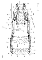
- FIG. 1 is a cross-sectional view of a lens barrel 10 according to an embodiment of the present invention cut along the optical axis A1. It is a figure which shows the state located.
- FIG. 2 is a diagram showing a state in which the third lens group 57A (adjustable movable lens group) shown in FIG. 1 is positioned on the telephoto side (telephoto side).
- the configuration of the lens barrel 10 is omitted as appropriate, and a plurality of lenses including convex lenses and concave lenses are illustrated in a state in which they are appropriately combined into one. etc. are omitted (the same applies to other figures).
- the lens barrel 10 of the present embodiment has a plurality of cylindrical portions and a lens system composed of a plurality of lenses (optical elements). A portion 30 , a focus mechanism portion 40 , and a zoom mechanism portion 50 . Also, the lens system has a plurality of lens groups each having one or more lenses, and part of the lens groups is configured as a moving lens group that moves along the optical axis direction (X direction) during zooming and focusing. .
- the outer cylinder 20 is a normal member that covers the outer peripheral side of each member of the lens barrel 10 .
- the outer cylinder 20 may be configured by combining a plurality of tubular members, or may be configured from a single tubular member.
- the fixed lens unit 30 is attached at its end to a camera body (not shown) of a camera device, which is an example of an imaging device having an imaging element. That is, the fixed lens section 30 is located on the rear side (X2 side) of the zoom mechanism section 50 in the optical axis direction (X direction).
- the fixed lens unit 30 has a fixed barrel 31, and a lens holding frame 32 is arranged inside the fixed barrel 31.
- a first lens group 33A which is one of the lens groups composed of a plurality of lenses 33, is arranged on the inner cylinder side of the fixed lens portion 30 with a lens holding frame 32 interposed therebetween.
- Each lens 33 of the first lens group 33A is fixed to the fixed barrel 31 and the lens holding frame 32 so as not to move.
- the lens holding frame 32 may be provided for each lens 33 or may hold several lenses 33 .
- the first lens group 33A is a lens group that does not move along the optical axis direction (X direction) during focusing and zooming.
- the focus mechanism section 40 is located on the front side (X1 side) in the optical axis direction (X direction) of the zoom mechanism section 50 .
- the focus mechanism section 40 includes a fixed barrel 41 similar to the fixed barrel 31 described above, and a lens holding frame 42 is arranged inside the fixed barrel 41 . Through this lens holding frame 42, therefore, a second lens group 43A, which is one of the lens groups composed of a plurality of lenses 43, is provided on the inner cylinder side of the focus mechanism section 40 through the lens holding frame 42. are placed.
- the lenses 43 of the second lens group 43A include those that can move in the optical axis direction (X direction) as the moving frames 44 and 45 move in the optical axis direction (X direction). Focus adjustment is possible by moving the lenses 431 and 432 (lenses 431 and 432). In this case, lenses 431 and 432 are each one of the moving lens groups.
- the second lens group 43A includes two moving lens groups consisting of a lens 431 or a lens 432, and two lenses that are arranged on the X1 side of the lens 431 and between the lens 431 and the lens 432 and that do not move during focusing. It consists of four lens groups with
- the moving frame 44 and the moving frame 45 are located on the rear side (X2 side) of the lens 43 on the front side (X1 side) in the optical axis direction (X direction).
- lens 431 is preferably moved.
- the lens holding frame 42 may be provided for each lens 43 or may hold several lenses 43 .
- FIG. 3 is a partial cross-sectional view showing an enlarged part of the zoom mechanism section 50.
- the zoom mechanism section 50 includes a fixed barrel 51, a cam barrel 52, a cam follower 53, a moving frame 54, a fixed lens holding frame 55, a movable lens holding frame 56, a lens It has a third lens group 57A, which is one of the moving lens groups composed of 571, 572, and 573 and which moves during zooming.
- the zoom mechanism section 50 also has a moving frame 58 and a lens 574 .
- the lens 571 corresponds to the first adjustment moving lens subgroup
- the lenses 572 and 573 correspond to the second adjustment moving lens subgroup.
- the fixed cylinder 51 is a cylindrical member, and most of it is arranged on the inner cylinder side of the cam cylinder 52 .
- the fixed barrel 51 is integrally fixed with the fixed barrels 31 and 41 via screws or the like.
- the fixed barrel 51 is provided so as not to move or rotate in the optical axis direction (X direction), like the fixed barrel 31 and the fixed barrel 41 described above.
- the fixed barrel 51 is provided with a long groove-shaped guide groove 511 along the optical axis direction (X direction) so as to pass through the inner barrel side (inner side) and the outer side of the fixed barrel 51 .
- a cam follower 53 which will be described later, is slidably positioned in the guide groove 511 .
- the cam follower 53 moves integrally with moving frames 54 and 58, which will be described later, and the tip of the cam follower 53 on the outer diameter side of the lens barrel 10 is located in a cam groove 521, which will be described later.
- the cam barrel 52 is a tubular member arranged facing the outer peripheral surface 51 a of the fixed barrel 51 and is rotatably attached to the fixed barrel 51 .
- 4A and 4B are diagrams showing the positional relationship between the guide groove 511 and the cam groove 521.
- FIG. 4A is a plan view of the zoom mechanism section 50, and FIG. be.
- a cam groove 521 having a predetermined length is provided on the inner cylinder side of the cam cylinder 52 .
- the cam groove 521 has a concave cross section and is formed obliquely with respect to the optical axis direction (X direction). Further, the tip of the cam follower 53 on the outer diameter side is inserted into the cam groove 521 .
- the cam follower 53 also enters the guide groove 511.
- the position of the cam follower 53 is restricted to a position where the guide groove 511 and the cam groove 521 overlap (overlapping position).
- the cam groove 521 is formed obliquely with respect to the optical axis direction (X direction)
- the cam follower 53 positioned at the overlapping position moves in the optical axis direction (X direction).
- the moving frames 54 and 58, the fixed lens holding frame 55, the movable lens holding frame 56 and the third lens group 57A also move in the optical axis direction (X direction) via the cam follower 53.
- cam follower 53 attached to the outer diameter side of the flange portion 542 of the moving frame 54 enters both the guide groove 511 and the cam groove 521 at the overlapping position.
- cam follower 53 attached to the outer diameter side of the flange portion 581 of the moving frame 58 also enters both the guide groove 511 and the cam groove 521 at the overlapping position.
- the moving frame 54 corresponds to a part of the moving holding frame.
- the moving frame 54 is a member that moves inside the fixed barrel 51 as the cam follower 53 moves when the cam barrel 52 is rotated by an external force.
- the moving frame 54 is located on the front side (X1 side) in the optical axis direction (X direction) of the moving frame 58, and is used to move the lenses 571, 572, and 573 in the optical axis direction (X direction).
- the moving frame 58 is positioned on the rear side (X2 side) in the optical axis direction (X direction) of the moving frame 58, and is a frame member for moving the lens 574 in the optical axis direction (X direction). .
- the moving frame 54 is provided with a tubular portion 541 and a flange portion 542 .
- the moving frame 58 is a frame member for holding only the lens 574 and is not long in the optical axis direction (X direction). Therefore, although the moving frame 58 is provided with the flange portion 581 , a tubular portion corresponding to the tubular portion 541 is not provided. However, the moving frame 58 may be provided with a cylindrical portion.
- the tubular portion 541 of the moving frame 54 is a tubular portion, and the fixed lens holding frame 55 is held by the inner tubular portion on the front side (X1 side) in the optical axis direction (X direction). ing.
- a positioning recess 54a is provided at the end of the moving frame 54 on the front side (X1 side) in the optical axis direction (X1 direction).
- the positioning concave portion 54a is a concave portion into which the tip of a rod portion 633 described later is inserted, and the adjusting jig 60 is positioned with respect to the moving frame 54 by the insertion thereof.
- the flange portion 542 is a portion that protrudes radially outward from the rear side (X2 side) of the cylindrical portion 541 in the optical axis direction (X direction).
- the flange portions 542 are provided in a predetermined number (preferably three or more) in the circumferential direction of the tubular portion 541, and the flange portions 542 protrude at predetermined intervals in the circumferential direction. That is, the flange portion 542 is not provided over the entire circumference of the tubular portion 541 .
- the moving frame 54 is also provided with a first screw hole 543 (described later).
- the fixed lens holding frame 55 is arranged on the inner diameter side of the moving frame 54, and is a cylindrical member ( frame member). Note that the fixed lens holding frame 55 corresponds to a part of the movable holding frame.
- the fixed lens holding frame 55 is fixed to the front side (X1 side) of the moving frame 54 via an attachment flange portion 555 which will be described later, and does not move relative to the moving frame 54 .
- the fixed lens holding frame 55 is arranged on the outer diameter side of the movable lens holding frame 56 , and the inner peripheral side faces the outer peripheral side of the movable lens holding frame 56 .
- the fixed lens holding frame 55 is arranged so as to protrude rearward (X2 side) in the optical axis direction (X direction) from the movable lens holding frame 56. It is arranged so as to protrude forward (X1 side) in the optical axis direction (X direction) from the holding frame 55 .
- an upright wall 551 is provided upright toward the outer diameter side.
- An enlarged diameter portion 552 is provided from the tip of the outer diameter side of 551 toward the front side (X1 side).
- the enlarged diameter portion 552 is located radially outside the rear (X2 side) portion (referred to as a cylindrical portion 553) of the fixed lens holding frame 55 in the optical axis direction (X direction).
- a female screw portion 554 which will be described later, is provided on the inner surface side of the enlarged diameter portion 552 .
- the cylindrical portion 553 is provided with a second screw hole 556, which will be described later.
- a mounting flange portion 555 projecting radially outward is provided on the frontmost side of the enlarged diameter portion 552 in the optical axis direction (X direction). is attached to the front side (X1 side) of the moving frame 54 via screws or the like.
- the movable lens holding frame 56 is a tubular member (frame member) for holding the lenses 572 and 573 that constitute the third lens group 57A.
- the movable lens holding frame 56 is arranged radially inward of the fixed lens holding frame 55 , and its outer peripheral side faces the inner peripheral side of the fixed lens holding frame 55 . Further, the movable lens holding frame 56 is arranged so as to protrude forward (X1 side) in the optical axis direction (X direction) from the fixed lens holding frame 55 .
- a standing wall 561 standing toward the outer diameter side.
- a diameter-enlarged portion 562 is provided from the front side (X1 side).
- the standing wall 561 faces the standing wall 551 with a gap S formed therebetween.
- a wave spring W1 (corresponding to an elastic member) is arranged in this gap S, and this wave spring W1 exerts an urging force in a direction to separate the standing walls 551 and 561 from each other.
- the enlarged diameter portion 562 is located radially outside the rear (X2 side) portion (referred to as a cylindrical portion 563) of the movable lens holding frame 56 in the optical axis direction (X direction).
- a male threaded portion 564 as described later is provided on the outer surface side of the enlarged diameter portion 562 .
- annular flange portion 565 protrudes toward the outer diameter side.
- a gear portion 566 which will be described later, is formed on the outer peripheral surface located.
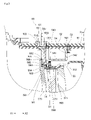
- FIG. 5 is a perspective view showing a state in which the vicinity of the fixed side hole 512 of the lens barrel 10 is cut along a plane perpendicular to the optical axis A1. 5, the outer cylinder 20 is omitted.
- the adjustment mechanism of this embodiment adjusts the distance between the lens 571 and the lenses 572 and 573 .
- This adjustment mechanism includes a fixed side hole portion 512, a cam side hole portion 522, a female screw portion 554 (corresponding to the inner peripheral engaging portion), a male screw portion 564 (the outer peripheral engaging portion), and a gear portion 566 ( corresponding to the drive transmission unit).
- a fixed side hole 512 is provided so as to pass through the fixed barrel 51 at a portion of the fixed barrel 51 that does not interfere with the guide groove 511 .
- a cam-side hole 522 is provided in a portion of the cam cylinder 52 that does not interfere with the cam groove 521 so as to penetrate the cam cylinder 52 .
- These fixed side hole portion 512 and cam side hole portion 522 are provided at positions where the fixed side hole portion 512 and the cam side hole portion 522 overlap when the cam barrel 52 is rotated with respect to the fixed barrel 51. there is That is, by inserting an adjusting jig, which will be described later, into the fixed side hole portion 512 and the cam side hole portion 522 , it is possible to make the adjusting jig protrude inside the cam cylinder 52 .
- the position where the fixed-side hole portion 512 and the cam-side hole portion 522 overlap is that the inner cylinder side of the fixed cylinder 51 and the outer cylinder side of the cam cylinder 52 overlap the fixed-side hole portion 512 and the cam-side hole portion. Communicate via the portion 522 (the inner cylinder side of the fixed cylinder 51 can be seen from the outer cylinder side of the cam cylinder 52).
- the fixed side hole portion 512 has a slit-shaped long groove portion 512a and a shaft groove portion 512b in the central portion in the longitudinal direction of the long groove portion 512a.
- the cam-side hole portion 522 has a slit-shaped long groove portion 522a and a shaft groove portion 522b in the longitudinal central portion of the long groove portion 522a.
- the adjustment gear 61 of the adjustment jig 60 is inserted into the long groove portions 512a and 522a.
- the rotary shaft 62 of the adjustment jig 60 is inserted into the shaft grooves 512b and 522b. That is, the adjusting jig 60 can be inserted into both the cam-side hole portion 522 and the fixed-side hole portion 512 .
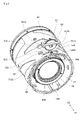
- FIGS. 6 and 7 when the fixed side hole portion 512 and the cam side hole portion 522 do not overlap and are misaligned, the adjustment gear 61 of the adjustment jig 60 is displaced. Even if the tip can be inserted into the cam-side hole 522 , the tip of the adjustment gear 61 collides with the outer peripheral surface 51 a of the fixed cylinder 51 and cannot be inserted into the fixed-side hole 512 .
- 6 is a plan view of the zoom mechanism unit 50 and shows a state in which the lens 571 held via the moving frame 54 is positioned on the telephoto side (telephoto side).
- FIG. 7 is a plan view of the zoom mechanism unit 50 and shows a state in which the lens 571 held via the moving frame 54 is positioned on the wide angle side (wide side).
- Such alignment of the fixed side hole portion 512 and the cam side hole portion 522 can be performed by rotating the cam tube 52 relative to the fixed tube 51 .
- a female screw portion 554 is provided on the inner surface side of the enlarged diameter portion 552 of the fixed lens holding frame 55 described above.
- a male screw portion 564 is provided on the outer surface side of the expanded diameter portion 562 of the movable lens holding frame 56 described above.
- the female threaded portion 554 and the male threaded portion 564 are screwed together. Therefore, when the movable lens holding frame 56 is rotated with respect to the fixed lens holding frame 55 by the adjustment jig 60, the movable lens holding frame 56 moves in the optical axis direction (X direction) with respect to the fixed lens holding frame 55. It is possible. Thereby, the distance between the lens 571 held by the fixed lens holding frame 55 and the lenses 572 and 573 held by the movable lens holding frame 56 can be adjusted.
- a gear portion 566 is provided on the outer peripheral surface of the annular flange portion 565 of the movable lens holding frame 56 .
- the gear portion 566 is a portion that meshes with an adjustment gear 61 of an adjustment jig 60, which will be described later.
- the gear portion 566 rotates.
- the movable lens holding frame 56 is configured to move in the optical axis direction (X direction) with respect to the fixed lens holding frame 55 .
- This position fixing mechanism has a first screw hole 543 , a second screw hole 556 , a fixing screw S ⁇ b>1 , a fixed side through hole 513 and a cam side through hole 523 .
- the first screw hole 543 corresponds to a screw hole.
- the moving frame 54 is provided with a first screw hole 543 penetrating the tubular portion 541, and a fixing screw S1 is screwed into the first screw hole 543.
- the fixed lens holding frame 55 is provided with a second screw hole 556 penetrating the cylindrical portion 553, and the fixing screw S1 described above is screwed into the second screw hole 556.
- the first screw hole 543 and the second screw hole 556 are aligned so that their positions in the optical axis direction (X direction) and circumferential direction are the same. Therefore, when the fixing screw S1 is screwed into the first screw hole 543 , the fixing screw S1 is also screwed into the second screw hole 556 and protrudes to the inner diameter side of the cylindrical portion 553 .
- the fixing screw S1 abuts on the outer peripheral surface of the movable lens holding frame 56. As shown in FIG. That is, after the optical performance evaluation described later is completed, the fixing screw S1 is screwed into the first screw hole 543 and the second screw hole 556 to bring the tip of the fixing screw S1 into contact with the movable lens holding frame 56. Then, the positions of the fixed lens holding frame 55 and the movable lens holding frame 56 are fixed and do not change. Thereby, the relative positions of the lens 571 and the lenses 572 and 573 are fixed.
- the fixing screw S1 is preferably a set screw without a head. In this case, the fixing screw S1 can be brought into a state in which it does not protrude from the first screw hole 543 toward the outer diameter side.
- a screw having a head may be used as the fixing screw S1.
- the fixed cylinder 51 is formed with a fixed side through hole 513 penetrating through the fixed cylinder 51 .
- the fixing screw S ⁇ b>1 and a tool for screwing the fixing screw S ⁇ b>1 are inserted into the fixed-side through hole 513 .
- the cam cylinder 52 is formed with a cam-side through hole 523 that penetrates the cam cylinder 52.
- This cam-side through hole 523 also has the above-described fixing screw S1 and this screw. A tool for screwing in the fixing screw S1 is inserted.
- the cam-side hole portion 522 is aligned with the fixed-side hole portion 512 , the cam-side through hole 523 and the first screw hole 543 , the second screw hole 556 and the fixed-side through hole 513 They are positioned so as to exist on the same straight line.
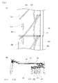
- FIG. 8 is an exploded perspective view showing the configuration of the adjusting jig 60.
- the adjusting jig 60 has an adjusting gear 61, a rotary shaft 62, and a gear support portion 63.
- the adjustment gear 61 is a member that is rotatably supported by the rotary shaft 62 and meshes with the gear portion 566 described above. Therefore, when the adjusting gear 61 rotates, the movable lens holding frame 56 can be rotated.
- the rotating shaft 62 is a shaft-like member that rotatably supports the adjusting gear 61 .
- the gear support portion 63 is a portion that rotatably supports the adjustment gear 61 .
- the gear support portion 63 has a base portion 631 , a shaft support portion 632 and a rod portion 633 .
- the base portion 631 is a frame-shaped portion having an elongated hole 631a into which the adjusting gear 61 can be inserted, and supports the adjusting gear 61 through the rotating shaft 62 so as to be rotatable.
- Abutment projections 631b protruding downward are provided on both ends of the base portion 631 in the longitudinal direction. As a result, the rest of the base portion 631 is prevented from coming into contact with the outer peripheral surface of the cam cylinder 52, so that the adjustment gear 61 can rotate stably.
- the shaft support portion 632 is a portion that protrudes further downward from the lower surface of the center of the base portion 631 in the longitudinal direction, and is a portion that is inserted into the above-described shaft groove portions 512b and 522b.
- the shaft support portion 632 is provided with a hole portion 632a into which the rotating shaft 62 is inserted. Therefore, the shaft support portion 632 rotatably supports the adjustment gear 61 via the rotation shaft 62 .
- the rod portion 633 is a rod-shaped portion that protrudes downward from one shaft support portion 632 .
- the rod portion 633 may be provided completely separately from the one shaft support portion 632 .
- This rod portion 633 is a portion that is fitted into the positioning recess 54a provided on the outer peripheral surface of the moving frame 54 on the front side (X1 side). A relative position is defined.
- the lens 571 held by the fixed lens holding frame 55 and the movable lens holding frame 56 are moved from the outside of the lens barrel 10 using the adjustment jig 60 .
- the distance between the held lenses 572 and 573 can be adjusted.
- the cam cylinder 52 is rotated relative to the fixed cylinder 51 so that the fixed-side hole 512 and the cam-side hole 522 are positioned in a communicating position (overlapping position).
- the adjusting gear 61 of the adjusting jig 60 is inserted into the fixed-side hole 512 and the cam-side hole 522 so that the rod portion 633 of the gear support portion 63 enters the positioning concave portion 54a of the moving frame 54. Align.
- the tooth profile of the adjustment gear 61 is in a state of meshing with the gear portion 566 provided on the annular flange portion 565 of the movable lens holding frame 56 . That is, relative rotation between the fixed barrel 51 and the cam barrel 52 causes the movable lens holding frame 56 to move in the optical axis direction (X direction) via the moving frame 54 .
- the gear portion 566 also moves in the direction perpendicular to the optical axis direction (X direction). It overlaps with the fixed side hole portion 512 and the cam side hole portion 522 .
- the contact projection 631b of the base portion 631 is in contact with the outer peripheral surface of the cam cylinder 52 .
- the screw action between the female threaded portion 554 and the male threaded portion 564 causes the movable lens holding frame 56 to move toward the fixed lens holding frame 55 in the optical axis direction (X direction). ).
- the distance (lens spacing) between the lenses 572 and 573 held by the movable lens holding frame 56 and the lens 571 held by the fixed lens holding frame 55 changes. Therefore, after setting an appropriate lens spacing, optical performance evaluation such as various aberrations is evaluated, and as a result, if the lens spacing needs to be readjusted, the adjustment gear 61 is rotated again, and the fixed lens holding frame is rotated.
- the movable lens holding frame 56 is moved in the optical axis direction (X direction) with respect to 55 .
- optical performance evaluation falls within the prescribed standards.
- the fixing screw S1 is screwed into the first screw hole 543 and the second screw hole 556, and the tip of the fixing screw S1 is brought into contact with the movable lens holding frame 56.
- the positions of the fixed lens holding frame 55 and the movable lens holding frame 56 are fixed and do not change, so that the relative positions of the lens 571 and the lenses 572 and 573 are fixed.
- the cam side hole portion 522 and the cam It is preferable to block the side through hole 523 and the like with a tape or the like.
- the lens barrel 10 configured as described above includes a fixed barrel 51 in which a guide groove 511 is formed along the optical axis direction (X direction) and into which the cam follower 53 is inserted, and a fixed barrel 51 that is rotatable relative to the fixed barrel 51. , a cam cylinder 52 having a cam groove 521 in which the cam follower 53 is inserted and inclined with respect to the optical axis direction (X direction), and a third lens group 57A (moving lens group, A zoom mechanism unit 50 that changes the focal length by moving an adjustment moving lens group), and a third lens group 57A (moving lens group, adjustment moving lens group) that is at least one of the lens groups. and an adjustment mechanism for adjusting the position of at least one lens 573 (optical element, first adjustment moving lens) in the optical axis direction (X direction).
- the zoom mechanism 50 (moving mechanism) has a cam follower 53 and a moving frame 54 that moves in the optical axis direction (X direction) as the cam barrel 52 rotates relative to the fixed barrel 51. (moving holding frame), a movable lens holding frame 56 that holds at least one lens 573 (optical element, second adjusting moving lens subgroup) of the third lens group 57A (moving lens group, adjustment moving lens group), contains.
- the adjustment mechanism includes a fixed side hole 512 that penetrates the fixed barrel 51 and a cam barrel 52 that penetrates and is aligned with the fixed side hole 512 when the cam barrel 52 rotates with respect to the fixed barrel 51 .
- a gear portion 566 drive transmission portion
- a female threaded portion 554 inner peripheral engagement portion
- a female threaded portion 554 outer peripheral engaging portion
- a male screw portion 564 peripheral engaging portion
- the adjusting gear 61 of the adjusting jig 60 is fixed from the outside. It is inserted into the side hole portion 512 and the cam side hole portion 522 to engage the adjustment gear 61 of the adjustment jig 60 with the gear portion 566 (driving transmission portion).
- the lens barrel 10 can be disassembled. There is no need to adjust the lens spacing of the third lens group 57A (moving lens group, adjustment moving lens group). In addition, after disassembling the lens barrel 10 and adjusting the lens spacing of the third lens group 57A (moving lens group, adjustment moving lens group), it is not necessary to assemble the lens barrel 10 again. , the man-hours can be reduced. In addition, when the lens barrel 10 is disassembled and assembled, it is possible to prevent problems such as dust from entering the interior and scratches on the lens.
- the gear portion 566 driving transmission portion
- the adjustment gear 61 the engagement between the female screw portion 554 (inner peripheral engaging portion) and the female screw portion 554 (inner peripheral engaging portion) is caused.
- the movable lens holding frame 56 moves in the optical axis direction (X direction) with respect to the fixed lens holding frame 55 (moving holding frame).
- the adjustment of the lens interval of the moving lens group) is no longer restricted by the line-up of shims and washers, and fine adjustment of the lens interval to 0.01 mm or less, for example, becomes possible.
- the fixed side hole portion 512 and the cam side hole portion 522 can be adjusted while viewing the projected image and measured values of the lens barrel 10. It is possible to finely adjust the lens spacing of the third lens group 57A (moving lens group, adjustment moving lens group) by inserting the adjusting jig 60 from the outside through the optical performance.
- the ratings can be within the prescribed standards.
- the third lens group 57A (adjustable movable lens group) has at least lens 571 (first adjustable movable lens subgroup) and lenses 572 and 573 (second adjustable movable lens subgroup).
- the lens 571 (first adjustable movable lens subgroup) is held by the fixed lens holding frame 55 (movable holding frame)
- the lenses 572 and 573 (second adjustable movable lens subgroup) are held by the movable lens holding frame 56.
- the lens 571 (first adjustment moving lens subgroup) held by the fixed lens holding frame 55 (moving holding frame) and the lenses 572 and 573 held by the movable lens holding frame 56 (second adjustment moving It is possible to finely adjust the lens spacing between the lens subgroups.
- this embodiment includes a position fixing mechanism that fixes the positions of the fixed lens holding frame 55 and the movable lens holding frame 56 after the adjustment of the gap between the fixed lens holding frame 55 and the movable lens holding frame 56 is completed.
- the position fixing mechanism includes a first screw hole 543 (screw hole) penetrating the cylindrical portion 541 of the moving frame 54 (moving holding frame) and a fixing screw screwed into the first screw hole 543 (screw hole). S1 and the fixed cylinder 51 are penetrated to allow the fixing screw S1 to pass therethrough.
- cam-side hole portion 522 When the cam-side hole portion 522 is aligned with the fixed-side hole portion 512 and the cam-side hole portion 522 is aligned with the fixed-side hole portion 512 while the screw S1 is inserted, it is aligned with the first screw hole 543, the second screw hole 556, and the fixed-side through hole 513. and a cam-side through-hole 523 existing in the .
- the fixing screw S1 is inserted into the fixed side hole 512 and the cam side hole. 522 and screwed into the first screw hole 543 (screw hole), the tip of the fixing screw S1 can be brought into contact with the movable lens holding frame 56 .
- the positions of the fixed lens holding frame 55 and the movable lens holding frame 56 can be fixed and not changed, thereby fixing the relative positions of the lens 571 and the lenses 572 and 573. can.
- the fixed-side through hole 513 is provided at a position that does not interfere with the fixed-side hole portion 512
- the cam-side through hole 523 is provided at a position that does not interfere with the cam-side hole portion 522.
- the fixing screw S1 can be inserted through the fixed-side through hole 513 and the cam-side through hole 523. , the fixing screw S1 can be screwed into the first screw hole 543 (screw hole).
- the moving frame 54 is provided with a positioning concave portion 54a (positioning engagement portion) for positioning the adjusting jig 60 to be inserted from the outside.
- the adjusting jig 60 can be positioned at an appropriate position with respect to the gear portion 566. This makes it possible to easily adjust the lens spacing of the third lens group 57A (adjustable movable lens group).
- a wave spring W1 (elastic member) is provided in the gap S between the fixed lens holding frame 55 (movable holding frame) and the movable lens holding frame 56 to urge both members in a direction to separate them from each other. are placed.
- only one fixed side hole 512 and one cam side hole 522 are provided in the optical axis direction (X direction).
- a configuration in which a plurality of fixed side holes 512 and cam side holes 522 are provided in the optical axis direction (X direction) may be adopted.
- a set of the fixed side hole 512 and the cam side hole 522 can be provided, for example, on the wide angle side (wide side) and the telephoto side (telephoto side).
- the moving frame 54, the fixed lens holding frame 55, and the movable lens holding frame 56 are positioned on the wide-angle side (wide side), and the optical performance is evaluated while the lens spacing of the third lens group 57A (adjustable moving lens group) is adjusted. can make adjustments.
- the lens interval of the third lens group 57A (adjustable movable lens group) is adjusted while the optical performance is evaluated by positioning the moving frame 54, the fixed lens holding frame 55 and the movable lens holding frame 56 on the telephoto side (telephoto side). can do As a result, it is possible to realize a state in which the optical performance is within a predetermined standard on both the wide angle side (wide side) and the telephoto side (telephoto side) without disassembling the lens barrel 10 .
- the lens 571 first adjustment movement lens subgroup
- the lenses 572 and 573 second adjustment movement
- the lens interval of the lens group is adjusted.
- the adjustment mechanism similar to that of the present embodiment may be used to adjust the lens spacing of other lenses in the third lens group 57A (adjustment moving lens group).
- the lens spacing in the second lens group 43A of the focus mechanism section 40 may be adjusted using an adjustment mechanism similar to that of the present embodiment. Accordingly, the focal length or focus position may be changed.
- all the third lens group 57A (lenses 571, 572, 573) are held in the movable lens holding frame 56, the fixed lens holding frame 55 is omitted, and the third lens group is adjusted to the entire optical system by the adjustment mechanism.
- the position of 57A may be adjusted (the distance between the third lens group 57A and the adjacent lens group in the optical axis direction of the third lens group 57A may be adjusted).
- the lens barrel 10 is attached to an imaging device such as a camera body of a camera device, and when the lens barrel 10 is attached to the camera body, it constitutes an interchangeable lens camera.
- the lens barrel 10 may be attached to a camera body in which lenses cannot be exchanged.
- the lens barrel 10 may be attached to a separate optical device such as a projection device such as a projector device.
- the moving frame 54 is provided with the positioning recess 54a (positioning engaging portion) for positioning the adjustment jig 60 to be inserted from the outside.
- the fixed lens holding frame 55 may be provided with a positioning recess (positioning engaging portion) similar to the positioning recess 54a.
- the positioning engaging portion is not limited to the positioning concave portion, and may be a positioning convex portion.
- the moving frame 54 and the fixed lens holding frame 55 are described as separate members, but the moving frame 54 and the fixed lens holding frame 55 do not move in the optical axis direction during zooming ( It is integrated both during movement in the X direction) and during adjustment by the adjusting mechanism. Therefore, since the fixed lens holding frame 55 can be regarded as a part of the moving frame 54, the moving frame 54 and the fixed lens holding frame 55 may be one member. For example, by connecting the front (X1 side) end of the moving frame 54 and the rear (X2 side) end of the fixed lens holding frame 55, both members can be integrally molded. In that case, the tubular portion 541 of the moving frame 54 and the tubular portion 553 of the fixed lens holding frame 55 are integrated into one tubular portion. The screw hole 543 becomes unnecessary and there is only one screw hole.
- the gear portion 566 is described as the drive transmission portion.
- the drive transmission portion is not limited to the gear portion, and may have, for example, an uneven portion on which the tip of a pin inserted from the outside is caught.
- the female threaded portion 554 is described as the inner peripheral engaging portion
- the male threaded portion 564 is described as the outer peripheral engaging portion.
- the inner peripheral engaging portion is not limited to the female screw portion 554 and the outer peripheral engaging portion is not limited to the male screw portion 564 .
- a helical cam groove is formed on the inner peripheral surface of the tubular portion 553, and this cam groove is used as an inner peripheral engaging portion
- a cam follower is formed on the outer peripheral surface of the tubular portion 563, and the cam follower is formed on the outer peripheral surface. It is good also as an engagement part.
- a cam follower is formed on the inner peripheral surface of the cylindrical portion 553, and this cam follower serves as an inner peripheral engaging portion, and a spiral cam groove is formed on the outer peripheral surface of the cylindrical portion 563, and this cam groove is formed on the outer peripheral surface. It is good also as an engagement part.
- the wave spring W1 is described as an elastic member, but the elastic member is not limited to the wave spring W1.
- an elastic body such as a coil spring or elastomer may be used as the elastic member.
- an image pickup device having an image sensor is not limited to a camera device.
- various inspection devices may be used as imaging devices.
- an image display device having an image display element may include the above lens barrel. In that case, it is possible to employ a configuration in which an image display element is arranged on the telephoto side of the lens barrel according to the above embodiment.
- Female screw part (inner circumference 555... Mounting flange portion 556... Second screw hole (corresponding to screw hole) 561... Standing wall 562... Enlarged diameter part 563... Cylindrical part 564... Male screw part (peripheral engaging part) 565... Annular flange part 566... Gear part (corresponding to drive transmission part) 571... Lens (corresponding to adjustment moving lens group and first adjusting moving lens sub group) 572... Lens (adjusting movement lens group and second adjustment moving lens subgroup), 573... lens (corresponding to adjustment moving lens group, second adjustment moving lens subgroup and optical element), 581... flange portion, 631... base portion, 631a... long hole , 631b... Abutment convex part 632... Axial support part 632a... Hole part 633... Rod part A1... Optical axis S... Gap S1... Fixing screw W1... Wave spring (corresponding to elastic member)
Abstract
Description
Another aspect of the present invention is preferably an imaging apparatus including the lens barrel according to the invention described above and an imaging device arranged on the telephoto side of the lens barrel.
図1は、本発明の一実施の形態に係るレンズ鏡筒10を光軸A1に沿って切断した断面図であり、広角側(ワイド側)に第3レンズ群57A(調整移動レンズ群)が位置している状態を示す図である。また、図2は、図1に示す第3レンズ群57A(調整移動レンズ群)が望遠側(テレ側)に位置している状態を示す図である。なお、図1、図2では、適宜、レンズ鏡筒10の構成を必要に応じて省略して示していると共に、凸レンズおよび凹レンズを含む複数のレンズを適宜、1つにまとめた状態で図示する等の省略を行っている(他の図でも同様)。 [About configuration]
FIG. 1 is a cross-sectional view of a
次に、調整機構について説明する。図5は、レンズ鏡筒10のうち、固定側孔部512付近を光軸A1に垂直な平面で切断した状態を示す斜視図である。なお、図5においては、外筒20は省略された状態で示されている。本実施の形態の調整機構は、レンズ571とレンズ572,573との間隔の調整を行うものである。この調整機構は、固定側孔部512と、カム側孔部522と、雌ネジ部554(内周係合部に対応)と、雄ネジ部564(外周係合部)と、ギヤ部566(駆動伝達部に対応)とを備えている。 (Regarding the adjustment mechanism)
Next, the adjustment mechanism will be explained. FIG. 5 is a perspective view showing a state in which the vicinity of the fixed
上述した調整機構での、固定レンズ保持枠55(レンズ571)と可動レンズ保持枠56(レンズ572,573)の間隔調整が終了した後に、両者の位置を固定するために、レンズ鏡筒10には位置固定機構が設けられている。この位置固定機構は、第1ネジ孔543と、第2ネジ孔556と、固定用ネジS1と、固定側貫通孔513と、カム側貫通孔523とを有している。なお、第1ネジ孔543は、ネジ孔に対応する。 (Regarding the position fixing mechanism)
After the adjustment of the distance between the fixed lens holding frame 55 (lens 571) and the movable lens holding frame 56 (
以上のような構成のレンズ鏡筒10においては、調整用治具60を用いて、レンズ鏡筒10の外部から、固定レンズ保持枠55に保持されているレンズ571と、可動レンズ保持枠56に保持されているレンズ572,573の間隔調整を行える。 [About action]
In the
以上のような構成のレンズ鏡筒10は、光軸方向(X方向)に沿うと共にカムフォロワ53が入り込むガイド溝511が形成されている固定筒51と、固定筒51に対して回転可能に設けられ、カムフォロワ53が入り込むと共に光軸方向(X方向)に対して傾斜しているカム溝521を有するカム筒52と、レンズ群のうちの少なくとも一つである第3レンズ群57A(移動レンズ群、調整移動レンズ群)を移動させることで、焦点距離を変化させるズーム機構部50と、レンズ群のうちの少なくとも一つである第3レンズ群57A(移動レンズ群、調整移動レンズ群)を構成する少なくとも一つのレンズ573(光学素子、第1調整移動レンズ)の光軸方向(X方向)の位置を調整するための調整機構と、を備えている。 [About effect]
The
以上、本発明の一実施の形態について説明したが、本発明はこれ以外にも種々変形可能となっている。以下、それについて述べる。 [Modification]
Although one embodiment of the present invention has been described above, the present invention can be variously modified. This will be discussed below.
Claims (9)
- 一枚以上の光学素子を有するレンズ群を複数有するレンズ系を内部に保持するレンズ鏡筒であって、
光軸方向に沿うと共にカムフォロワが入り込むガイド溝が形成されている固定筒と、
前記固定筒に対して回転可能に設けられ、前記カムフォロワが入り込むと共に前記光軸方向に対して傾斜しているカム溝を有するカム筒と、
前記レンズ群のうち少なくとも一つのレンズ群を移動レンズ群として光軸方向に移動させることで、焦点距離またはピント位置を変化させる移動機構部と、
少なくとも一つの前記移動レンズ群である調整移動レンズ群を構成する少なくとも一つの前記光学素子の前記光軸方向の位置を調整するための調整機構と、
を備え、
前記移動機構部は、
前記カムフォロワが取り付けられていると共に、前記固定筒に対する前記カム筒の相対的な回転に伴って光軸方向に移動する移動保持枠と、
前記移動レンズ群の少なくとも一部の光学素子を保持する可動レンズ保持枠と、
を含み、
前記調整機構は、
前記固定筒を貫く固定側孔部と、
前記カム筒を貫くと共に該カム筒が前記固定筒に対して回転した際に前記固定側孔部に対して位置合わせされるカム側孔部と、
前記固定側孔部および前記カム側孔部が位置合わせされた状態でこれらと同一直線上の前記可動レンズ保持枠の外周側に設けられる駆動伝達部と、
前記移動保持枠の内周面に形成されている内周係合部と、
前記可動レンズ保持枠の外周面に前記内周係合部と係合する状態で形成され、前記駆動伝達部を介して回転方向へ外力が伝達された際に、前記内周係合部に対して回転することで前記光軸方向へ前記可動レンズ保持枠を移動させる外周係合部と、
を有することを特徴とするレンズ鏡筒。 A lens barrel internally holding a lens system having a plurality of lens groups each having one or more optical elements,
a fixed cylinder formed with a guide groove along the optical axis direction and into which the cam follower is inserted;
a cam cylinder provided rotatably with respect to the fixed cylinder and having a cam groove into which the cam follower is inserted and which is inclined with respect to the optical axis direction;
a moving mechanism that changes a focal length or a focus position by moving at least one of the lens groups as a moving lens group in an optical axis direction;
an adjustment mechanism for adjusting the position in the optical axis direction of at least one optical element that constitutes an adjustment moving lens group that is at least one of the moving lens groups;
with
The moving mechanism unit
a movement holding frame to which the cam follower is attached and which moves in the optical axis direction as the cam barrel rotates relative to the fixed barrel;
a movable lens holding frame that holds at least a part of the optical element of the movable lens group;
including
The adjustment mechanism is
a fixed side hole extending through the fixed cylinder;
a cam-side hole that penetrates the cam barrel and is aligned with the fixed-side hole when the cam barrel rotates with respect to the fixed barrel;
a drive transmission portion provided on the outer peripheral side of the movable lens holding frame on the same straight line with the fixed side hole and the cam side hole in a state where they are aligned;
an inner peripheral engaging portion formed on the inner peripheral surface of the moving holding frame;
It is formed on the outer peripheral surface of the movable lens holding frame in a state of being engaged with the inner peripheral engaging portion, and when an external force is transmitted in the rotational direction via the drive transmission portion, the an outer periphery engaging portion that rotates to move the movable lens holding frame in the optical axis direction;
A lens barrel characterized by having: - 請求項1記載のレンズ鏡筒であって、
前記調整移動レンズ群は、少なくとも第1調整移動レンズ小群および第2調整移動レンズ小群を有し、
前記第1調整移動レンズ小群は、前記移動保持枠に保持され、
前記第2調整移動レンズ小群は、前記可動レンズ保持枠に保持される、
ことを特徴とするレンズ鏡筒。 The lens barrel according to claim 1,
the adjusting moving lens group has at least a first adjusting moving lens subgroup and a second adjusting moving lens subgroup;
The first adjustment moving lens subgroup is held by the movement holding frame,
The second adjustment moving lens subgroup is held by the movable lens holding frame,
A lens barrel characterized by: - 請求項1または2記載のレンズ鏡筒であって、
前記調整機構での前記固定レンズ保持枠と前記可動レンズ保持枠の間隔の調整が終了した後に、両者の位置を固定する位置固定機構を備え、
前記位置固定機構は、
前記移動保持枠が備える筒状部を貫くネジ孔と、
前記ネジ孔に捻じ込まれる固定用ネジと、
前記固定筒を貫通し、前記固定用ネジを挿通させると共に、前記ネジ孔と同一直線上に存在する固定側貫通孔と、
前記カム筒を貫通し、前記固定用ネジを挿通させると共に、前記固定側孔部に対して前記カム側孔部が位置合わせされた際に、前記ネジ孔および前記固定側貫通孔と同一直線上に存在するカム側貫通孔と、
を備えることを特徴とするレンズ鏡筒。 3. The lens barrel according to claim 1 or 2,
a position fixing mechanism for fixing the positions of the fixed lens holding frame and the movable lens holding frame after the adjustment of the gap between the fixed lens holding frame and the movable lens holding frame by the adjustment mechanism is completed;
The position fixing mechanism is
a screw hole penetrating the cylindrical portion of the moving holding frame;
a fixing screw to be screwed into the screw hole;
a fixed-side through-hole that passes through the fixed cylinder and allows the fixing screw to pass therethrough, and that exists on the same straight line as the screw hole;
The fixing screw penetrates through the cam cylinder, and is on the same straight line as the screw hole and the fixed-side through hole when the cam-side hole is aligned with the fixed-side hole. A cam-side through-hole present in
A lens barrel comprising: - 請求項3記載のレンズ鏡筒であって、
前記固定側貫通孔は、前記固定側孔部と干渉しない位置に設けられていると共に、
前記カム側貫通孔は、前記カム側孔部とは干渉しない位置に設けられている、
ことを特徴とするレンズ鏡筒。 The lens barrel according to claim 3,
The fixed-side through hole is provided at a position that does not interfere with the fixed-side hole,
The cam-side through hole is provided at a position that does not interfere with the cam-side hole,
A lens barrel characterized by: - 請求項1から4のいずれか1項に記載のレンズ鏡筒であって、
前記移動保持枠には、外部から挿入する調整用治具の位置決めを行うための位置決め係合部が設けられている、
ことを特徴とするレンズ鏡筒。 The lens barrel according to any one of claims 1 to 4,
The moving holding frame is provided with a positioning engaging portion for positioning an adjustment jig inserted from the outside.
A lens barrel characterized by: - 請求項1から5のいずれか1項に記載のレンズ鏡筒であって、
前記移動保持枠と前記可動レンズ保持枠の間の隙間には、両部材を互いに離間させる向きに付勢する弾性部材が配置されている、
ことを特徴とするレンズ鏡筒。 The lens barrel according to any one of claims 1 to 5,
An elastic member is arranged in a gap between the movable holding frame and the movable lens holding frame to urge both members in a direction to separate them from each other.
A lens barrel characterized by: - 請求項5記載のレンズ鏡筒であって、
複数の前記固定側孔部および前記カム側孔部が前記光軸方向において離れた位置に設けられている、
ことを特徴とするレンズ鏡筒。 The lens barrel according to claim 5,
wherein the plurality of fixed side holes and the plurality of cam side holes are provided at positions separated in the optical axis direction,
A lens barrel characterized by: - 請求項1から7のいずれか1項に記載のレンズ鏡筒と、当該レンズ鏡筒の望遠側に配置される撮像素子とを有する撮像装置。 An imaging apparatus comprising the lens barrel according to any one of claims 1 to 7, and an imaging element arranged on the telephoto side of the lens barrel.
- 請求項1から7のいずれか1項に記載のレンズ鏡筒と、当該レンズ鏡筒の望遠側に配置される画像表示素子とを有する画像表示装置。 An image display device comprising the lens barrel according to any one of claims 1 to 7 and an image display element arranged on the telephoto side of the lens barrel.
Priority Applications (3)
| Application Number | Priority Date | Filing Date | Title |
|---|---|---|---|
| JP2023508735A JPWO2022201877A1 (en) | 2021-03-23 | 2022-02-01 | |
| US18/550,465 US20240053577A1 (en) | 2021-03-23 | 2022-02-01 | Lens barrel |
| EP22774679.9A EP4318068A1 (en) | 2021-03-23 | 2022-02-01 | Lens barrel |
Applications Claiming Priority (2)
| Application Number | Priority Date | Filing Date | Title |
|---|---|---|---|
| JP2021-048784 | 2021-03-23 | ||
| JP2021048784 | 2021-03-23 |
Publications (1)
| Publication Number | Publication Date |
|---|---|
| WO2022201877A1 true WO2022201877A1 (en) | 2022-09-29 |
Family
ID=83396776
Family Applications (1)
| Application Number | Title | Priority Date | Filing Date |
|---|---|---|---|
| PCT/JP2022/003798 WO2022201877A1 (en) | 2021-03-23 | 2022-02-01 | Lens barrel |
Country Status (4)
| Country | Link |
|---|---|
| US (1) | US20240053577A1 (en) |
| EP (1) | EP4318068A1 (en) |
| JP (1) | JPWO2022201877A1 (en) |
| WO (1) | WO2022201877A1 (en) |
Citations (4)
| Publication number | Priority date | Publication date | Assignee | Title |
|---|---|---|---|---|
| JPH0996750A (en) * | 1995-09-29 | 1997-04-08 | Fuji Photo Optical Co Ltd | Tracking mechanism for camera |
| JPH11337799A (en) * | 1998-05-26 | 1999-12-10 | Ricoh Co Ltd | Lens barrel |
| WO2012128203A1 (en) * | 2011-03-24 | 2012-09-27 | 富士フイルム株式会社 | Lens device |
| WO2012128202A1 (en) * | 2011-03-23 | 2012-09-27 | 富士フイルム株式会社 | Lens device |
-
2022
- 2022-02-01 JP JP2023508735A patent/JPWO2022201877A1/ja active Pending
- 2022-02-01 EP EP22774679.9A patent/EP4318068A1/en active Pending
- 2022-02-01 US US18/550,465 patent/US20240053577A1/en active Pending
- 2022-02-01 WO PCT/JP2022/003798 patent/WO2022201877A1/en active Application Filing
Patent Citations (4)
| Publication number | Priority date | Publication date | Assignee | Title |
|---|---|---|---|---|
| JPH0996750A (en) * | 1995-09-29 | 1997-04-08 | Fuji Photo Optical Co Ltd | Tracking mechanism for camera |
| JPH11337799A (en) * | 1998-05-26 | 1999-12-10 | Ricoh Co Ltd | Lens barrel |
| WO2012128202A1 (en) * | 2011-03-23 | 2012-09-27 | 富士フイルム株式会社 | Lens device |
| WO2012128203A1 (en) * | 2011-03-24 | 2012-09-27 | 富士フイルム株式会社 | Lens device |
Also Published As
| Publication number | Publication date |
|---|---|
| EP4318068A1 (en) | 2024-02-07 |
| US20240053577A1 (en) | 2024-02-15 |
| JPWO2022201877A1 (en) | 2022-09-29 |
Similar Documents
| Publication | Publication Date | Title |
|---|---|---|
| JP4953874B2 (en) | Lens barrel, imaging device, and information terminal device | |
| JP5779179B2 (en) | Lens unit | |
| US9354419B2 (en) | Adjustment device, lens barrel, and optical apparatus | |
| KR101084861B1 (en) | Lens barrel and camera including it | |
| US6570719B2 (en) | Lens barrel and method of assembling the same | |
| JP6533961B2 (en) | Lens barrel and optical axis adjustment method | |
| US10995831B2 (en) | Lens barrel and cam follower | |
| JP2010169915A (en) | Projection lens and method for manufacturing projection lens | |
| JP2008046439A (en) | Lens barrel with tilt adjusting mechanism | |
| US8125722B2 (en) | Lens device | |
| US7782557B2 (en) | Lens position adjusting device | |
| WO2022201877A1 (en) | Lens barrel | |
| US10495841B2 (en) | Lens barrel and imaging device | |
| JP5388624B2 (en) | Lens barrel and optical apparatus having the same | |
| JP5776179B2 (en) | Alignment mechanism, lens barrel and optical equipment | |
| US20210003907A1 (en) | Cam follower and lens barrel | |
| KR102658881B1 (en) | Camera lens assembly | |
| JP6929128B2 (en) | Manufacturing method of lens barrel | |
| JP2005274837A (en) | Eccentricity adjustment method of zoom lens | |
| JP6645291B2 (en) | Lens barrel | |
| WO2021065104A1 (en) | Lens barrel, lens device, and method for manufacturing lens barrel | |
| JP2010271525A (en) | Lens barrel and assembling method thereof | |
| JP2009244585A (en) | Lens barrel | |
| JP6828521B2 (en) | Alignment structure of the lens barrel and the lens barrel | |
| JP6805898B2 (en) | Rotational advance / retreat mechanism of lens barrel and lens barrel |
Legal Events
| Date | Code | Title | Description |
|---|---|---|---|
| 121 | Ep: the epo has been informed by wipo that ep was designated in this application |
Ref document number: 22774679 Country of ref document: EP Kind code of ref document: A1 |
|
| ENP | Entry into the national phase |
Ref document number: 2023508735 Country of ref document: JP Kind code of ref document: A |
|
| WWE | Wipo information: entry into national phase |
Ref document number: 18550465 Country of ref document: US |
|
| WWE | Wipo information: entry into national phase |
Ref document number: 2022774679 Country of ref document: EP |
|
| NENP | Non-entry into the national phase |
Ref country code: DE |
|
| ENP | Entry into the national phase |
Ref document number: 2022774679 Country of ref document: EP Effective date: 20231023 |