WO2022201412A1 - 描画処理装置、描画処理システム、描画処理方法、および描画処理プログラム - Google Patents
描画処理装置、描画処理システム、描画処理方法、および描画処理プログラム Download PDFInfo
- Publication number
- WO2022201412A1 WO2022201412A1 PCT/JP2021/012490 JP2021012490W WO2022201412A1 WO 2022201412 A1 WO2022201412 A1 WO 2022201412A1 JP 2021012490 W JP2021012490 W JP 2021012490W WO 2022201412 A1 WO2022201412 A1 WO 2022201412A1
- Authority
- WO
- WIPO (PCT)
- Prior art keywords
- target
- buffer
- rendering
- unit
- applicable
- Prior art date
- Legal status (The legal status is an assumption and is not a legal conclusion. Google has not performed a legal analysis and makes no representation as to the accuracy of the status listed.)
- Ceased
Links
Images













Classifications
-
- G—PHYSICS
- G06—COMPUTING OR CALCULATING; COUNTING
- G06T—IMAGE DATA PROCESSING OR GENERATION, IN GENERAL
- G06T15/00—Three-dimensional [3D] image rendering
Definitions
- the present disclosure relates to a drawing processing device that performs processing for drawing drawing information, a drawing processing system using the drawing processing device, a drawing processing method, and a drawing processing program.
- a 2D, 3D, etc. model drawing target may be displayed on a display device such as a display.
- a two-dimensional drawing target is drawn as it is in a drawing destination buffer, which is a drawing destination buffer, but a three-dimensional drawing target is projected two-dimensionally and then drawn in the drawing destination buffer.
- the draw target is drawn, if the center of a pixel in the draw destination buffer is included in the draw target, the pixel is filled. For this reason, for example, a small drawing target with a drawing size of less than 1 pixel disappears from the display screen without being drawn if the drawing target is not positioned at the center of the pixel.
- the entire scene including the drawing target is enlarged and drawn at a high resolution in a detail buffer, which is a buffer separate from the drawing destination buffer, and the detail buffer is drawn.
- a technique called supersampling is disclosed that reduces the size to the same size as the drawing destination buffer.
- Patent Document 1 is disclosed as a technique for drawing a drawing target in detail.
- a drawing processing device virtually divides each pixel vertically and horizontally into four, with one pixel being 16 sub-pixels, and among the 16 sub-pixels included in each pixel,
- a technology that aggregates the number of sub-pixels that exist inside, calculates the ratio of that number for each pixel as an alpha value that represents transparency, and uses the calculated alpha value to perform alpha blending between the drawing target and the background. is disclosed.
- the above-described supersampling and conventional rendering processing devices require rendering of the entire scene. For example, in order to draw a small drawing target of less than one pixel so as not to disappear from the display screen, it is necessary to draw the drawing target with a correspondingly higher magnification or a greater number of pixel divisions. However, if there are objects with a large difference in drawing size in the scene, if the whole scene is drawn with the magnification or division number corresponding to the smallest object, the other objects will also have high resolution or division number. Since drawing is performed with a large number, the drawing processing load increases.
- the present disclosure has been made to solve the above problems, and when drawing targets with a large difference in drawing size coexist in the same scene, draw so that the drawing targets do not disappear from the display screen. It is an object of the present invention to provide a drawing processing device, a drawing processing system, a drawing processing method, and a drawing processing program that can reduce the drawing processing load caused by drawing.
- the drawing processing apparatus includes an application determination unit that determines whether a drawing target is an applicable drawing target to which detailed drawing processing is applied or an unapplied drawing target to which detailed drawing processing is not applied. , a drawing unit that draws a drawing target determined by the application determination unit as an unapplied drawing target to a drawing destination buffer, and a drawing target determined by the application determination unit as an applicable drawing target has a resolution higher than that of the rendering destination buffer. An enlargement drawing part that expands and draws to the buffer, and a calculation part that reduces the detail buffer to the same size as the drawing destination buffer and calculates the alpha value that represents the transparency of the drawing target based on the drawing of the reduced detail buffer. a blend processing unit for alpha-blending a drawing target applied to a drawing destination buffer with an alpha value; and an output control unit for controlling to output a scene drawn in the alpha-blended drawing destination buffer to an output device.
- a drawing processing system includes an input device that receives input of a drawing target, a drawing processing device that performs drawing processing of drawing a drawing target as a scene in a drawing buffer, and an output device that outputs a scene.
- the device acquires a drawing target from the input device, and determines whether the drawing target is an applicable drawing target to which detailed drawing processing is applied or an unapplied drawing target to which detailed drawing processing is not applied.
- a drawing unit that draws a drawing target determined by the application determining unit as an inapplicable drawing target to a drawing destination buffer; and a drawing target determined as an applicable drawing target by the application determining unit from the drawing destination buffer
- An alpha value that represents the transparency of the object to be drawn based on the enlarged drawing part that expands and draws to the detail buffer, which is also high resolution, and reduces the detail buffer to the same size as the drawing destination buffer, based on the reduced detail buffer drawing
- a calculation unit that calculates , a blend processing unit that alpha-blends the drawing target applied to the drawing destination buffer with the alpha value, and an output control unit that controls so that the scene drawn in the alpha-blended drawing destination buffer is output to the output device.
- a drawing processing method includes a step of determining whether a drawing target is an applicable drawing target to which detailed drawing processing is applied or an unapplied drawing target to which detailed drawing processing is not applied; a step of drawing a drawing target determined as an applicable drawing target in a drawing destination buffer; a step of enlarging and drawing the drawing target determined as an applicable drawing target in a detail buffer having a higher resolution than the drawing destination buffer; reducing the buffer to the same size as the drawing destination buffer, calculating an alpha value representing the transparency of the applied drawing target based on the drawing of the reduced detail buffer; and controlling to output the scene drawn in the alpha-blended drawing destination buffer to an output device.
- a drawing processing program includes processing for determining whether a drawing target is an applicable drawing target to which detailed drawing processing is applied or an unapplied drawing target to which detailed drawing processing is not applied; A process of drawing a drawing target determined as an applicable drawing target to a drawing destination buffer, a process of enlarging and drawing a drawing target determined as an applicable drawing target to a detail buffer having a higher resolution than the drawing destination buffer, and a detailed drawing process.
- the buffer is reduced to the same size as the drawing destination buffer, and based on the drawing of the reduced detail buffer, the alpha value representing the transparency of the applied drawing target is calculated, and the alpha value is applied to the drawing destination buffer. and a process of controlling the scene drawn in the alpha-blended drawing destination buffer to be output to the output device.
- the application determination unit determines whether the drawing target is an applicable drawing target to which detailed drawing processing for drawing in detail is applied or an unapplied drawing target to which detailed drawing processing is not applied, and the drawing unit Renders the drawing target determined by the application determination unit to be an unapplied drawing target in the rendering destination buffer, and the enlargement rendering unit renders the rendering target determined by the application determination unit to be an applicable rendering target to have a higher resolution than the rendering destination buffer.
- the calculation unit reduces the detail buffer to the same size as the drawing destination buffer, calculates the alpha value that represents the transparency of the applied drawing target based on the drawing in the reduced detail buffer, and performs blending
- the part alpha blends the drawing target applied to the drawing destination buffer with the alpha value
- the output control part controls to output the scene drawn in the alpha blended drawing destination buffer to the output device, so there is no difference in drawing size in the same scene
- the drawing processing load can be reduced by drawing the objects so as not to disappear from the display screen.
- FIG. 1 is a block diagram of a drawing processing system including a drawing processing device according to Embodiment 1;
- FIG. 1 is a hardware configuration diagram of a drawing processing system according to Embodiment 1;
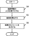
- FIG. 4 is a flowchart showing the operation of the drawing processing system according to Embodiment 1; It is an example of drawing information according to the first embodiment. 4 is a flowchart showing the operation of the drawing processing device according to Embodiment 1;
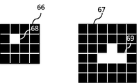
- 3A and 3B are diagrams of a drawing destination buffer and a detail buffer for enlarged drawing according to the first embodiment;
- FIG. FIG. 10 is a conceptual diagram showing roughly estimating the area of a drawing target by projecting a three-dimensional drawing target into two dimensions using a bounding box;
- FIG. 10 is a conceptual diagram showing roughly estimating the area of a drawing target by projecting a three-dimensional drawing target into two dimensions using a bounding box;
- FIG. 11 is a diagram in which a rendering result of rendering a polygon model for non-application rendering in a rendering destination buffer and the polygon model for non-application rendering are superimposed;
- FIG. 10 is a diagram showing a rendering result of rendering a non-applicable rendering target polygon model to a rendering destination buffer;
- FIG. 11 is a diagram in which a drawing result of drawing a polygon model to be applied drawing in a detailed buffer, a drawing result of drawing another polygon model to be applied drawing in a detail buffer, and a plurality of polygon models to be applied drawing are superimposed.
- FIG. 10 is a diagram showing a drawing result of drawing a polygon model to be applied drawing in the detail buffer and a drawing result of drawing another polygon model to be applied drawing in the detail buffer;
- FIG. 10 is a diagram showing a drawing result of drawing a polygon model to be applied drawing in the detail buffer and a drawing result of drawing another polygon model to be applied drawing in the detail buffer;
- FIG. 10 is a diagram showing a detail buffer that is a reduced detail buffer
- FIG. 4 is a diagram showing pixel correspondences between a detail buffer and a reduced detail buffer
- FIG. 10 is a diagram showing a rendering result of rendering all polygon models in a rendering destination buffer
- 8 is a block diagram of a drawing processing system including a drawing processing device according to Embodiment 2
- FIG. 9 is a flowchart showing operations of a drawing processing system according to Embodiment 2 of the present disclosure
- 9 is a flowchart showing operations of a drawing processing device according to Embodiment 2 of the present disclosure
- 10 is a block diagram of a drawing processing system including a drawing processing device according to Embodiment 3
- FIG. 11 is a flow chart showing the operation of a drawing processing device according to Embodiment 3 of the present disclosure
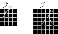
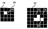
- FIG. FIG. 10 is a diagram showing a comparative relationship between a detail buffer corresponding to a polygon model to be applied drawing in the third embodiment, another detail buffer corresponding to a polygon model to be applied drawing, and the detail buffer of the first embodiment
- FIG. 14 is a diagram showing a detailed buffer corresponding to a polygon model to be applied drawing and another detailed buffer corresponding to another polygon model to be applied drawing according to the third embodiment
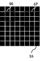
- FIG. 10 is a diagram schematically showing position information, which is information indicating which position in the drawing destination buffer the detail buffer corresponds to;
- FIG. 12 is a diagram schematically showing position information, which is information indicating to which position in the drawing destination buffer another detail buffer corresponds;
- FIG. 11 is a diagram schematically showing position information in which information indicating which position in the drawing destination buffer the detail buffer corresponds to and information indicating which position in the drawing destination buffer the other detail buffer corresponds to; be.
- the result of drawing a polygon model to be applied drawing to the detail buffer, the drawing result of drawing another polygon model to be applied drawing to another detail buffer, the polygon model to be applied drawing, and the polygon model to be applied drawing. is superimposed.
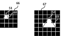
- FIG. 10 is a diagram showing a drawing result of drawing a polygon model to be applied drawing in a detail buffer and a drawing result of drawing another polygon model to be applied drawing in another detail buffer;
- FIG. 12 illustrates a detail buffer that is a reduced detail buffer and a detail buffer that is a reduced detail buffer;
- FIG. 10 illustrates pixel correspondences between a detail buffer and a reduced detail buffer and pixel correspondences
- Embodiment 1 a case where the present disclosure is applied to a case where drawing targets with a large drawing size difference are mixed in the same scene in drawing information that is information for drawing the entire scene will be described below. do.
- a drawing target is divided into a drawing target to which detailed drawing processing is applied and then drawn to a drawing destination buffer, and a drawing target to which detailed drawing processing is not applied and which is drawn to a drawing destination buffer. It is divided into non-applicable drawing targets that are drawn as they are.
- the drawing processing system draws the non-applicable drawing target to the drawing destination buffer as it is, enlarges the applicable drawing target to the detail buffer, which is a buffer separate from the drawing destination buffer, and then draws the alpha Calculate the value and the RGB values representing the color, and shrink the detail buffer to the same size as the destination buffer.
- the drawing processing system draws the applied drawing object in the drawing destination buffer by alpha-blending the RGB values of the applied drawing object with the alpha value of the applied drawing object calculated for the drawing destination buffer. By doing so, it is not necessary to apply detailed drawing processing to the entire scene, so the drawing processing load can be reduced by drawing so as not to cause the drawing target to disappear from the display screen. Details will be described below.
- FIG. 1 is a block diagram of a drawing processing system 1 including a drawing processing device 100 according to the first embodiment.
- the drawing processing system 1 uses an input device 4 for inputting tag information indicating whether or not to apply detailed drawing processing to each drawing object included in the drawing information and drawing information, and using the drawing information and the tag information, A drawing processing device 100 for drawing drawing information and an output device 5 for outputting a scene processed by the drawing processing device 100 are provided.
- the input device 4 receives, for example, the drawing information of the entire scene including the drawing target information such as the polygon model input by the user.
- the user tags each drawing object as to whether it is an applicable drawing object or an inapplicable drawing object by looking at the drawing size, brightness, importance, and the like.
- the input device 4 receives an input from the user for tagging each drawing target as tag information.
- the drawing processing device 100 performs a drawing process of drawing the drawing target included in the drawing information as a scene in the drawing destination buffer. Specifically, the rendering processing device 100 renders the non-applicable rendering target tagged as not applying the detailed rendering processing to the rendering destination buffer.
- the drawing processing device 100 enlarges and draws the application drawing target tagged as applying the detail drawing processing to a detail buffer, which is a buffer different from the drawing destination buffer.
- the drawing processing device 100 calculates the alpha value from the ratio of the drawn area at the time of enlargement.
- the drawing processing unit 100 calculates RGB values from the average values of the colors of the pixels that were colored during enlargement.
- the drawing processing unit 100 reduces the detail buffer to the same size as the drawing destination buffer.
- the drawing processing device 100 alpha blends the RGB values with the calculated alpha value and draws the applied drawing target in the drawing destination buffer. In this way, the rendering processing device 100 does not apply the detailed rendering processing to all rendering targets, but applies the detailed rendering processing only to the applicable rendering targets that require the detailed rendering processing, thereby reducing the rendering processing load. can be reduced.
- the output device 5 outputs the scene drawn in the drawing destination buffer by the drawing processing device 100 .
- the output device 5 is, for example, a display device such as a display, and displays the scene drawn in the drawing destination buffer by the drawing processing device 100 .
- the drawing processing device 100 includes an acquisition unit 101 that acquires drawing information including a drawing target and tag information from the input device 4, a creation unit 102 that creates a drawing buffer and a detail buffer, and a drawing target using the tag information.
- An application determination unit 106 for determining whether or not to perform detailed drawing processing, a rendering unit 107 for rendering non-applicable rendering targets tagged as not applying detailed rendering processing to a rendering destination buffer, and tagging when detailed rendering processing is applied.
- an enlargement drawing unit 108 for enlarging and drawing the applied drawing target to the detail buffer, and a calculating unit 109 for calculating the alpha value and RGB value of the applied drawing target and reducing the detail buffer to the same size as the drawing destination buffer.
- a blend processing unit 110 for alpha-blending the RGB values with alpha values to draw the applied drawing target in the drawing destination buffer
- an output control unit 111 for controlling output of the scene drawn in the drawing destination buffer to the output device 5.
- a drawing destination storage unit 103 for storing a drawing destination buffer
- an enlarged drawing storage unit 104 for storing a detailed buffer for enlarged drawing
- a reduced drawing storage unit 105 for storing a detailed buffer for reduction.
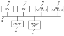
- the drawing processing system 1 includes a bus 41 , a CPU (Central Processing Unit) 42 , a main memory 43 , a GPU (Graphics Processing Unit) 44 , a graphic memory 45 , an input interface 46 and an output interface 47 .
- a CPU Central Processing Unit
- main memory 43 main memory
- GPU Graphics Processing Unit
- graphic memory 45 input interface 46 and output interface 47 .
- a bus 41 is a signal path that electrically connects devices and exchanges data.
- the devices and devices of the drawing processing system 1 are connected via communication.
- the communication used may be wired communication or wireless communication.
- the CPU 42 reads and executes programs stored in the main memory 43 . Specifically, the CPU 42 loads at least part of the OS (Operating System) stored in the main memory 42 and executes the program while executing the OS.
- the CPU 42 is connected to another device via the bus 41 and controls the device.
- the CPU 42 may be an IC (Integrated Circuit) that performs processing, and may be a microprocessor, microcomputer, or DSP (Digital Signal Processor).
- the main memory 43 stores programs and OSs describing software, firmware, or a combination of software and firmware.
- the main memory 43 also stores various information and the like.
- the main memory 43 is, for example, a volatile semiconductor memory such as RAM (Random Access Memory), ROM (Read Only Memory), flash memory, EPROM (Erasable Programmable Read Only Memory), EEPROM (Electrically Erasable Programmable Read Only).
- RAM Random Access Memory
- ROM Read Only Memory
- flash memory EPROM (Erasable Programmable Read Only Memory), EEPROM (Electrically Erasable Programmable Read Only).
- Non-volatile semiconductor memories such as HDDs (Hard Disk Drives), portable recording media such as magnetic disks, flexible disks, optical disks, compact disks, mini disks, and DVDs (Digital Versatile Discs).
- the GPU 44 reads the program stored in the graphic memory 45 and executes drawing processing. Specifically, the GPU 44 loads at least part of the OS stored in the graphic memory 45, and executes the drawing processing program while executing the OS.
- the acquisition unit 101, the creation unit 102, the application determination unit 16, the drawing unit 107, the enlarged drawing unit 108, the calculation unit 109, the blend processing unit 110, and the output control unit 111 of the drawing processing device 100 are: It is realized by the GPU 44 reading the program loaded into the graphic memory 45 and executing it.
- the graphic memory 45 stores programs and OSs describing software, firmware, or a combination of software and firmware. Also, the graphic memory 45 stores various information and the like.
- the graphic memory 45 includes, for example, volatile semiconductor memory such as RAM, ROM, flash memory, EPROM, EEPROM, nonvolatile semiconductor memory such as HDD, magnetic disk, flexible disk, optical disk, compact disk, mini disk, and DVD. A portable recording medium or the like.
- the acquisition unit 101, the creation unit 102, the application determination unit 106, the drawing unit 107, the enlarged drawing unit 108, the calculation unit 109, the blend processing unit 110, and the output control unit 111 of the drawing processing device 100 are: It is implemented by a program stored in the graphic memory 45 .
- a drawing destination storage unit 103 for storing a drawing destination buffer, an enlarged drawing storage unit 104 for storing a detailed buffer for enlarged drawing, and a reduced drawing storage unit 105 for storing a detailed buffer for reducing drawing are all connected to each other. Realized by memory 45 .
- Graphic memory 45 includes acquisition unit 101, creation unit 102, application determination unit 106, drawing unit 107, enlargement drawing unit 108, calculation unit 109, blend processing unit 110, and Each function with the output control unit 111 may be realized by separate memories. Also, the drawing destination storage unit 103, the enlarged drawing storage unit 104, and the reduced drawing storage unit 105 may be realized by separate memories.
- the processing including the drawing processing performed by the drawing processing device 100 is performed by the GPU 44 and the graphic memory 45, and the processing other than the processing including the drawing processing performed by the drawing processing device 100 is performed by the CPU 42 and the main memory 43.
- the drawing processing system 1 may be provided with either the CPU 42 or the GPU 44, and the provided one may realize all the processing. Alternatively, the drawing processing system 1 may be provided with only one of the main memory 43 and the graphic memory 45, and the provided memory may realize the same function as the other memory.
- Information of each part may be stored in either the main memory 43 or the graphic memory 45 . Information of each part may be stored by combining the main memory 43 and the graphic memory 45 .
- the input interface 46 is a device that allows input of drawing information and tag information.
- the input interface 46 is, for example, input using a keyboard, mouse, voice input, etc., and reception of information via communication.
- the input device 4 is implemented by an input interface 46 .
- the output interface 47 is a device that outputs rendered scenes.
- the output interface 47 is, for example, a display device such as a display or a projector.
- the output device 5 is implemented by an output interface 47 .
- Each function of the drawing processing system 1 can be realized by hardware, software, firmware, or a combination thereof.
- Each function of the drawing processing system 1 may be partly realized by dedicated hardware and partly realized by software or firmware.
- a part of the drawing processing system 1 realizes its function by a processing circuit as dedicated hardware, and the remaining part realizes its function by reading and executing a program stored in the memory by the CPU. good too.
- Software, firmware, or a combination of software and firmware may be described as a program.
- FIG. 3 is a flow chart showing the operation of the drawing processing system 1 according to the first embodiment. The operation of the drawing processing system 1 will be described below with reference to FIG.
- step S1 the input device 4 accepts input of drawing information including a drawing target.
- drawing information including a drawing target.
- a user uses a mouse, a keyboard, or the like to specify drawing information and input it to the input device 4, and the input device 4 receives the input.
- the drawing information received by the input device 4 may be drawing information received via communication, drawing information automatically extracted that satisfies a predetermined criterion, or drawing information extracted by machine learning, even if the drawing information is not specified by the user. Any information such as drawing information can be used.
- the drawing target is a three-dimensional polygon model and the drawing information includes information on the drawing target, which is the polygon model.
- the information of the object to be drawn, which is a polygon model includes RGB values, position information, and the like.
- FIG. 4 is an example of drawing information according to the first embodiment.
- the drawing information includes a polygon model 51, a polygon model 52, and a polygon model 53 to be drawn.
- the polygon models 51 to 53 are displayed as if drawn on a buffer of the same size as the drawing buffer so that the drawing flow can be easily understood.
- the input device 4 receives input of drawing information and tag information indicating whether a drawing target included in the received drawing information is an applicable drawing target or an unapplied drawing target.
- the tag information corresponds to each drawing target.
- the user can determine whether the polygon model to be drawn is large enough to avoid detailed drawing processing, or whether the polygon model to be drawn is large enough to be drawn in detail. Determine whether the size is small enough to process.
- the user uses the mouse, keyboard, voice input, etc., to tag each drawing target as non-applicable drawing targets that are determined to be large size, and applicable drawing targets that are determined to be small size.
- the tag information is input to the input device 4 .
- the input device 4 receives the input.
- the user determines that the size of the polygon models 51 and 52 is small enough to perform the detailed drawing process for the drawing information of FIG. 4, and the polygon model 53 is not subjected to the detailed drawing process. Assume that the user determines that the size is large enough to be acceptable.
- the input device 4 receives, input by the user, tag information tagged with the polygon model 51 as the applicable drawing target, tag information tagged with the polygon model 52 as the applicable drawing target, and the polygon model 53 . Suppose that it receives tag information tagged as being an inapplicable drawing target.
- the criterion for determining whether a drawing target is an applicable drawing target or an inapplicable drawing target is not limited to the size of the drawing target.
- the user may determine whether it is an applicable drawing target or an unapplied drawing target based on luminance, importance, or the like.
- the user may determine whether an object is an applicable drawing target or an unapplied drawing target based on a combination of drawing size, brightness, importance, and the like.
- the user may set a drawing target with a high degree of importance as an applicable drawing target and a drawing target with a low degree of importance as an unapplied drawing target.
- the user regards the drawing target as an applicable drawing target, and the other drawing targets as non-applicable drawing targets. good too. Whether the drawing target is the applicable drawing target or the non-applying drawing target may be determined according to the user's preference.
- the input device 4 transmits the drawing information and the tag information to the drawing processing device 100, and proceeds to step S2.
- step S2 the drawing processing device 100 receives drawing information and tag information from the input device 4.
- the drawing processing device 100 performs drawing processing using the received drawing information and tag information. Details will be described later.
- the drawing processing device 100 controls the output device 5 to output the scene drawn in the drawing destination buffer, and proceeds to step S3.
- step S3 the output device 5 outputs the scene drawn in the drawing destination buffer to a display device such as a display under the control of the drawing processing device 100.
- a display device such as a display under the control of the drawing processing device 100.
- step S3 Even after executing step S3, the process returns to step S1, and the above process is repeated until there is a trigger to end the process, such as turning off the power or performing an end operation. Although the above processing is repeated, it may be performed only once.
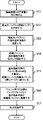
- FIG. 5 is a flow chart showing the operation of the rendering processing device 100 according to the first embodiment. The operation of the rendering processing apparatus 100 will be described below with reference to FIG.
- step S ⁇ b>11 the acquisition unit 101 acquires drawing information and tag information from the input device 4 .
- the acquisition unit 101 transmits the drawing information and the tag information to the creation unit 102, and proceeds to step S12.
- step S ⁇ b>12 the creation unit 102 receives the drawing information and the tag information from the acquisition unit 101 and creates a drawing destination buffer in the drawing destination storage unit 103 .
- the creating unit 102 also creates a detailed buffer for enlarged drawing in the enlarged drawing storage unit 104 . All applicable drawing objects are drawn in the detail buffer. Note that the detail buffer for enlarged drawing has a higher resolution than the drawing destination buffer.
- FIG. 6 is a diagram of the drawing destination buffer 55 and the detail buffer 56 for enlarged drawing according to the first embodiment.
- the drawing destination buffer 55 is 8 pixels long by 8 pixels wide, for a total of 64 pixels.
- the detail buffer 56 for enlarged drawing is 16 pixels high by 16 pixels wide, for a total of 256 pixels. That is, it is assumed that the detail buffer 56 for enlarged drawing has an enlargement ratio four times that of the drawing destination buffer 55 . Since the enlargement ratio corresponds to the resolution, the resolution of the detail buffer 56 at the time of enlarged drawing is four times that of the drawing destination buffer 55 .
- the enlargement ratio of the detail buffer when enlarging the drawing destination buffer may be determined in advance, or may be determined by the user upon receipt of input from the user, or may be determined by the drawing size of the drawing target.
- the method of determining the enlargement ratio is not limited, for example, it is determined according to the size of the image.
- the creation unit 102 may calculate the area of each drawing target, or use a bounding box or the like to roughly estimate the area of each drawing target. You may In the case of a three-dimensional object to be drawn, the size of the object to be drawn is calculated after the object to be drawn is projected and transformed into two dimensions.
- FIG. 7 is a conceptual diagram showing how a bounding box 80 is used to project and transform a three-dimensional drawing target 81 into a two-dimensional drawing target 81 to roughly calculate the area of the drawing target 81 .
- a three-dimensional drawing target 81 in the shape of a house is surrounded by a bounding box 80, and the area 82 of the bounding box 80 corresponding to the surface to be projected and transformed into two dimensions is divided by three. It is assumed to be an approximate value of the area of the drawing object 81 when the dimensional drawing object 81 is projected and transformed into two dimensions.
- one surface of the bounding box 80 exactly overlaps the surface to be projected and transformed into two dimensions. , the approximate value of the area of the drawing object 81 when the three-dimensional drawing object 81 is projected and transformed into two dimensions can be obtained. Also, although parallel projection has been described with reference to FIG. 7, perspective projection or the like is also applicable.
- the bounding box 80 is used to project the three-dimensional drawing object 81 into two dimensions, and the area of the drawing object 81 is roughly calculated.
- the drawing processing load can be reduced compared to obtaining the area of . Note that the more complicated the shape of the drawing target 81, the higher the drawing processing load. Roughly estimating the area increases the effect of reducing the drawing processing load.
- the creation unit 102 transmits the drawing information and the tag information to the application determination unit 106, and proceeds to step S13.
- step S13 the application determination unit 106 receives the drawing information and the tag information from the creation unit 102, and uses the tag information to determine whether the drawing target is an applicable drawing target or an unapplied drawing target. .
- the application determination unit 106 transmits the drawing information and all of the tag information of the drawing target that is the non-applicable drawing target to the drawing unit 107 .
- the drawing unit 107 receives the drawing information and the tag information of the non-applicable drawing target from the application determining unit 106 , and draws the non-applicable drawing target in the drawing destination buffer of the drawing destination storage unit 103 .
- the applicability determination unit 106 transmits the drawing information and the tag information of the polygon model 53 tagged as being the non-applicable drawing target to the drawing unit 107 with respect to the drawing information of FIG. .
- the rendering unit 107 receives the rendering information from the application determination unit 106 and the tag information of the polygon model 53 tagged as being the non-applicable rendering target, and stores the polygon model 53 in the rendering destination buffer 55 of the rendering destination storage unit 103 . to draw.
- FIG. 8 is a diagram in which the drawing result 54 obtained by drawing the non-applicable drawing target polygon model 53 in the drawing destination buffer 55 and the non-applicable drawing target polygon model 53 are superimposed.
- the rendering unit 107 fills the pixels in the rendering destination buffer 55 with RGB values associated with the rendering target included in the rendering information so as to resemble the shape of the polygon model 53.
- FIG. 9 is a diagram showing a drawing result 54 obtained by drawing the non-applied drawing target polygon model 53 in the drawing destination buffer 55 .
- FIG. 9 eliminates the superimposed display of the polygon model 53 of FIG. 8 and shows only the actual rendering result 54 .
- the drawing unit 107 when the drawing unit 107 finishes drawing the non-applicable drawing target in the drawing destination buffer, the drawing unit 107 notifies the application processing unit 106 and the blend processing unit 110 of the end of drawing in the drawing destination buffer. It transmits, and it progresses to step S14.
- step S ⁇ b>14 when the application determination unit 106 receives the notification of the end of drawing to the drawing destination buffer from the drawing unit 107 , the application determination unit 106 transmits the drawing information and the tag information of the drawing target, which is the applicable drawing target, to the enlargement drawing unit 108 . do.
- the application determining unit 106 adds the drawing information, the tag information of the polygon model 51 tagged as the applicable drawing target, and the tag as the applicable drawing target to the drawing information of FIG.
- the tag information of the attached polygon model 52 is transmitted to the enlargement drawing unit 108 .
- the enlarged drawing unit 108 receives the drawing information and the tag information of the drawing target, which is the applicable drawing target, from the application determining unit 106, and enlarges and draws the applicable drawing target in the detail buffer of the enlarged drawing storage unit 104.
- the enlargement drawing unit 108 receives the drawing information from the application determination unit 106, the tag information of the polygon model 51 tagged as the applicable drawing target, and the polygon model 51 tagged as the applicable drawing target. It receives the tag information of the model 52 and enlarges and draws the polygon models 51 to 52 in the detail buffer 56 of the enlarged drawing storage unit 104 .
- the enlargement ratio for enlarging and drawing the polygon models 51 to 52 in the detail buffer 56 is the same as the enlargement ratio for the detail buffer 56 with respect to the drawing destination buffer 55 .
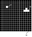
- FIG. 10 shows a drawing result 57 obtained by drawing a polygon model 51 to be applied drawing in the detail buffer 56, a drawing result 58 obtained by drawing another polygon model 52 to be applied drawing in the detail buffer 56, and a plurality of polygon models to be applied drawing. 51 and 52 are superimposed.
- the enlargement rendering unit 108 enlarges the polygon models 51-52 by a factor of four, which is the same as the enlargement ratio of the detail buffer 56 with respect to the rendering destination buffer 55, and enlarges the polygon models 51-52.
- Pixels in the detail buffer 56 are filled with the RGB values associated with the drawing object contained in the drawing information so as to resemble the shape.
- FIG. 11 shows a drawing result 57 obtained by drawing the polygon model 51 to be applied drawing in the detail buffer 56 and a drawing result 58 obtained by drawing another polygon model 52 to be applied drawing in the detail buffer 56 .
- FIG. 11 eliminates the superimposed display of the polygon models 51-52 of FIG. 10 and shows only the actual drawing results 57-58.
- the polygon model 51 is drawn in the drawing destination buffer 55 as it is, the polygon model 51 does not include the center of the pixel and disappears without being drawn. , the polygon model 51 is drawn without disappearing because the center of the pixel is included in one pixel.
- the enlargement drawing unit 108 transmits a notice of completion of enlargement drawing to the calculation unit 109, and proceeds to step S15.
- step S ⁇ b>15 upon receiving the enlarged drawing end notification from the enlarged drawing unit 108 , the calculation unit 109 reduces the detail buffer stored in the enlarged drawing storage unit 104 to the same size as the drawing destination buffer, and performs reduced drawing. Stored in the storage unit 105 .
- the reduction ratio when the calculation unit 109 reduces the detail buffer to the same size as the drawing destination buffer is the reciprocal of the enlargement ratio of the detail buffer to the drawing destination buffer when the detail buffer was created.
- the calculating unit 109 calculates the alpha value of each pixel in the drawing destination buffer of the applied drawing target from the ratio of filled pixels in the detail buffer before reduction using the reduction ratio.
- the calculating unit 109 calculates the RGB value of each pixel in the drawing destination buffer of the applied drawing target from the average value of the RGB values of the filled pixels in the detail buffer before reduction using the reduction ratio.
- the calculation unit 109 reduces the detail buffer to the same size as the drawing destination buffer using the reduction ratio and the RGB value of each pixel, and stores the alpha value and RGB value for each pixel.
- the calculation unit 109 upon receiving the notification of the end of enlarged drawing from the enlarged drawing unit 108, stores the detail buffer 56 stored in the enlarged drawing storage unit 104 in the drawing at the time when the detail buffer 56 was created.
- the size of the detail buffer 56 is reduced to 1/4, which is the reciprocal of 4 times the enlargement ratio of the detail buffer 56 with respect to the destination buffer 55, so that the size of the destination buffer 55 is the same.
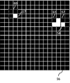
- FIG. 12 is a diagram showing a detail buffer 59 obtained by reducing the detail buffer 56.
- FIG. FIG. 12 shows a detail buffer 59 obtained by reducing the detail buffer 56 stored in the enlarged drawing storage unit 104 which the calculation unit 109 wants to create finally to 1/4 times.
- a drawing result 57 obtained by drawing the polygon model 51 in the detail buffer 56 is reflected in one pixel 60 in FIG.
- a drawing result 58 obtained by drawing the polygon model 52 in the detail buffer 56 is reflected in one pixel 61 to 62 in FIG.
- FIG. 13 is a diagram showing pixel correspondences between the detail buffer 56 and the reduced detail buffer 59 .
- a range 60 including a drawing result 57 obtained by drawing the polygon model 51 in FIG. 13 in the detail buffer 56 corresponds to one pixel 60 in FIG.
- a range 61 including a part of the rendering result 58 obtained by rendering the polygon model 52 in FIG. 13 in the detail buffer 56 corresponds to one pixel 61 in FIG. 13 corresponds to one pixel 62 in FIG.
- the calculation unit 109 calculates the alpha value of each pixel in the rendering destination buffer 55 of the polygon models 51 and 52 from the ratio of filled pixels in the detail buffer 56 before reduction using a reduction ratio of 1/4. . Specifically, since the range 60 in FIG. 13 corresponds to one pixel 60 in FIG. 12, if one pixel is painted in the range 60 in FIG. .25. Therefore, the alpha value of 1 pixel 60 in FIG. 12 can be calculated as 0.25. The calculator 109 stores an alpha value of 0.25 in one pixel 60 in FIG. The value in one pixel 60 of FIG. 12 represents the alpha value.
- the alpha value of 1 pixel 61 in FIG. 12 can be calculated as 0.75.
- the calculator 109 stores an alpha value of 0.75 in one pixel 61 in FIG.
- the value in one pixel 61 in FIG. 12 represents the alpha value.
- 13 corresponds to one pixel 62 in FIG. 12, so if one pixel is painted in the range 62 in FIG. Become. Therefore, the alpha value of 1 pixel 62 in FIG. 12 can be calculated as 0.25.
- the calculator 109 stores an alpha value of 0.25 in the 1 pixel 62 of FIG.
- the value in one pixel 62 of FIG. 12 represents the alpha value.
- the calculation unit 109 calculates each pixel in the drawing destination buffer 55 of the polygon models 51 and 52 from the average value of the RGB values of the filled pixels in the detail buffer 56 before reduction using a reduction ratio of 1/4. Calculate the RGB values of . Specifically, among the four pixels in FIG. 13 corresponding to one pixel in FIG. 12, the average value of the RGB values of the filled pixels is taken as the RGB value of one pixel in FIG.
- one pixel 60 in FIG. 12 has the same RGB values as the polygon model 51, and one pixel 61 to 62 in FIG. If there are multiple polygon models with different RGB values among the 4 pixels in FIG. 13 corresponding to 1 pixel of 12, the pixels will not have the same RGB values as the polygon model and will be filled with multiple polygon models. is the RGB value of one pixel in FIG. By doing so, the calculation unit 109 can calculate the optimum RGB values.
- the calculation unit 109 stores in the reduced drawing storage unit 105 the reduced detail buffer 59 including the alpha value and RGB value information for each pixel of each applicable drawing target.
- the calculation unit 109 transmits a notification of completion of calculation processing to the blend processing unit 110, and proceeds to step S16.
- step S ⁇ b>16 the blend processing unit 110 receives from the rendering unit 107 the notification of the end of rendering to the rendering destination buffer, and upon receiving the notification of the end of the calculation processing from the calculation unit 109 , the blend processing unit 110 stores the result in the rendering destination storage unit 103 .
- the detail buffer stored in the reduced drawing storage unit 105 is alpha-blended for each pixel with respect to the drawing destination buffer, and the applied drawing object is drawn in the drawing destination buffer.
- the blend processing unit 110 receives from the rendering unit 107 the notification of the end of rendering to the rendering destination buffer, and from the calculation unit 109 the notification of the end of calculation processing.
- the blend processing unit 110 renders the rendering destination buffer 55 stored in the rendering destination storage unit 103 with an alpha value of 0.25 for one pixel 60 of the detail buffer 59 stored in the reduced rendering storage unit 105 .
- the blend processing unit 110 assigns an alpha value of 0.0 for one pixel 61 of the detail buffer 59 stored in the reduced drawing storage unit 105 to the drawing destination buffer 55 stored in the rendering destination storage unit 103 .
- the blend processing unit 110 sets the alpha value of 0.0 for one pixel 62 of the detail buffer 59 stored in the reduced drawing storage unit 105 to the drawing destination buffer 55 stored in the rendering destination storage unit 103 .
- FIG. 14 is a drawing showing the result of drawing all the polygon models in the drawing destination buffer 55.
- FIG. A drawing result 63 is obtained by drawing the polygon model 51 in the drawing destination buffer 55 .
- Drawing results 64 and 65 are obtained by drawing the polygon model 52 in the drawing destination buffer 55 .
- a drawing result 54 is obtained by drawing the polygon model 53 in the drawing destination buffer 55 .
- the drawing result 54 in FIG. 14 is the same as the drawing result 54 in FIG.
- the blend processing unit 110 transmits a notification of the end of alpha blending to the output control unit 111, and proceeds to step S17.
- step S ⁇ b>17 the output control unit 111 receives the alpha blend end notification from the blend processing unit 110 and controls the output device 5 to output the drawing destination buffer stored in the drawing destination storage unit 103 .
- the output control unit 111 receives an alpha blend end notification from the blend processing unit 110 and outputs the scene drawn in the drawing destination buffer 55 stored in the drawing destination storage unit 103 .
- the display device which is the output device 5, is controlled.
- step S17 Even after executing step S17, the process returns to step S11, and the above process is repeated until there is a trigger to end the process, such as turning off the power or performing an end operation. Although the above processing is repeated, it may be performed only once.
- the rendering unit 107 selects a rendering target determined as an unapplied rendering target by the application determination unit 106 as a rendering destination stored in the rendering destination storage unit 103. Rendering is performed in a buffer, and the drawing target determined by the application determination unit 106 to be the applicable drawing target is enlarged by the enlargement rendering unit 108 to a detail buffer having a higher resolution than the rendering destination buffer stored in the enlargement drawing storage unit 104. , the calculation unit 109 calculates the alpha value representing the transparency of the applied drawing target, reduces the detail buffer to the same size as the drawing destination buffer, and the blend processing unit 110 transfers the calculated alpha value to the drawing destination buffer.
- the applied drawing target is alpha-blended, and the output control unit 111 controls to output the alpha-blended drawing destination buffer to the output device 5. Therefore, when drawing targets with a large drawing size difference coexist in the same scene, the entire scene is not required to be drawn with a high resolution or with a large number of divisions, the drawing processing load can be reduced by drawing the drawing target so as not to disappear from the display screen.
- Embodiment 2 In the first embodiment, in the drawing processing system 1, the input device 4 receives input of drawing information and tag information, the acquisition unit 101 acquires the drawing information and tag information from the input device 4, and the application determination unit 106 receives Using the tag information, it was determined whether the drawing target was the applicable drawing target or the non-applying drawing target.
- the input device 6 In the second embodiment, as shown in FIGS. 15 to 17, in the drawing processing system 2, the input device 6 only receives input of drawing information, and the obtaining unit 201 obtains the drawing information from the input device 6. , the application determination unit 202 determines whether the drawing target is the applicable drawing target or the non-applied drawing target based on the drawing information.
- the drawing processing system 2 automatically determines whether the drawing target is an applicable drawing target or an unapplied drawing target. load can be reduced.
- the drawing processing system 1 collectively draws both the non-applicable drawing target and the applicable drawing target. I will draw. Other than that, it is the same as the first embodiment.
- the configurations and operations described in Embodiment 1 are denoted by the same reference numerals, and duplicate descriptions are omitted.
- the present disclosure is applied to the case where the drawing information, which is the information for drawing the entire scene, includes drawing objects with a large drawing size difference in the same scene.
- drawing information which is the information for drawing the entire scene
- drawing objects with a large drawing size difference in the same scene.
- FIG. 15 is a block diagram of the drawing processing system 2 including the drawing processing device 200 according to the second embodiment.
- the drawing processing system 2 includes an input device 6 to which drawing information is input, a drawing processing device 200 that uses the drawing information to draw the drawing information, and an output that outputs the scene processed by the drawing processing device 200.
- the input device 4 of FIG. instead of the input device 6, an acquisition unit 201, an application determination unit 202, a drawing unit 203, an enlarged drawing unit 204, a calculation unit 205, a blend processing unit 207, an end determination unit 206, and an accumulation A storage unit 208 is added as a configuration of the functional block diagram.
- the input device 6 accepts, for example, only the drawing information of the entire scene including the drawing target information such as the polygon model input by the user.
- the drawing processing device 200 includes an acquisition unit 201 that acquires drawing information from the input device 6, a creation unit 102 that creates a drawing buffer and a detail buffer, and a device that determines whether or not to perform detailed drawing processing on a drawing target from the drawing information.
- a determination unit 202, a rendering unit 203 that draws an unapplied drawing target tagged as not applying detailed drawing processing to a drawing destination buffer, and an applicable drawing target tagged as applying detailed drawing processing is expanded to the detailed buffer.
- a calculation unit 205 that calculates the alpha value and RGB values of the applicable drawing target and reduces the detail buffer to the same size as the drawing destination buffer; an end judgment unit 206 for judging the end based on whether or not there is a drawing target that has not been drawn in the buffer; a blend processing unit 207 for alpha-blending the RGB values with the alpha value and drawing the applied drawing target in the drawing destination buffer; An output control unit 111 for controlling output of a scene drawn in a drawing destination buffer to the output device 5, a drawing destination storage unit 103 for storing the drawing destination buffer, and an enlarged drawing storage for storing a detailed buffer for enlarged drawing. a reduction drawing storage unit 105 for storing detail buffers used for reduction;
- a hardware configuration diagram of the drawing processing system 2 is the same as that of FIG. 2 of the first embodiment.
- the hardware configuration of the input device 6 is the same as that of the input device 4.
- the hardware configuration of the acquisition unit 201 is the same as that of the acquisition unit 101 .
- the hardware configuration of the application determination unit 202 is the same as that of the application determination unit 106 .
- the hardware configuration of the rendering unit 203 is the same as that of the rendering unit 107 .
- the hardware configuration of the enlarged drawing unit 204 is the same as that of the enlarged drawing unit 108 .
- the hardware configuration of the calculator 205 is the same as that of the calculator 109 .
- the hardware configuration of the blend processing unit 207 is the same as that of the blend processing unit 110 .
- the termination determination unit 206 is implemented by a program stored in the graphic memory 45, and is implemented by reading and executing the program loaded into the graphic memory 45 by the GPU 44.
- the accumulation storage unit 208 is implemented by the graphic memory 45 .
- graphic memory 45 may implement the functions of the end determination unit 206 and the functions of other units in separate memories. Also, the accumulation storage unit 208 and other storage units may be realized by separate memories. Other than that, the hardware configuration is the same as that of the first embodiment.
- FIG. 16 is a flowchart showing the operation of the drawing processing system 2 according to Embodiment 2 of the present disclosure. The operation of the drawing processing system 2 will be described below with reference to FIG.
- step S4 the input device 6 accepts input of drawing information.
- drawing information For example, a user uses a mouse, a keyboard, or the like to specify drawing information and input it to the input device 6, and the input device 6 receives the input.
- the drawing information received by the input device 6 is automatically extracted from the drawing information received via communication and the drawing information that satisfies a predetermined criterion without being specified by the user. Any drawing information may be used, such as drawing information extracted by machine learning.
- the rendering target is a three-dimensional polygon model and the rendering information includes information on the rendering target, which is the polygon model.
- Embodiment 2 as in Embodiment 1, a case where the present disclosure is applied to FIG. 4 will be described below.
- the input device 6 transmits the drawing information to the drawing processing device 200, and proceeds to step S5.
- step S ⁇ b>5 the drawing processing device 200 receives drawing information from the input device 6 .
- the drawing processing device 200 performs drawing processing using the received drawing information. Details will be described later.
- the drawing processing device 200 controls the output device 5 to output the scene drawn in the drawing destination buffer, and proceeds to step S6.
- step S6 the output device 5 outputs the scene drawn in the drawing destination buffer to a display device such as a display under the control of the drawing processing device 200, as in step S3 of the first embodiment.
- step S6 Even after executing step S6, the process returns to step S4, and the above process is repeated until there is a trigger to end the process, such as turning off the power or performing an end operation. Although the above processing is repeated, it may be performed only once.
- FIG. 17 is a flowchart showing the operation of the drawing processing device 200 according to Embodiment 2 of the present disclosure. The operation of the rendering processing device 200 will be described below with reference to FIG.
- step S21 the acquisition unit 201 acquires drawing information from the input device 6.
- the acquisition unit 201 transmits the drawing information to the creation unit 102, and proceeds to step S22.
- step S22 the creation unit 102 receives the drawing information from the acquisition unit 201.
- the creation unit 102 transmits the drawing information to the application determination unit 202, and proceeds to step S23.
- step S22 is the same as step S12 of the first embodiment.
- all applicable drawing targets are drawn in the detail buffer, but in the second embodiment, one applicable drawing target is drawn.
- the application determination unit 202 receives the drawing information from the creation unit 102.
- the application determination unit 202 uses the drawing information to determine whether one of the drawing targets included in the drawing information is an applicable drawing target or an unapplied drawing target.
- the application determination unit 202 calculates the area s of the object to be drawn and determines whether or not the area s is less than the threshold value X that is determined and stored in advance.
- Threshold X is a size large enough for the user not to perform detailed drawing processing on the drawing target, such as 1.0 pixels or 5.0 pixels, or a size small enough to perform detailed drawing processing. do it.
- the area s of the object to be drawn may be calculated by calculating the area of the object to be drawn itself, or by roughly estimating the area of the object to be drawn using a bounding box, etc. good too.
- the approximate area value of the polygon model 51 in FIG. 4 is 0.4 pixels
- the approximate area value of the polygon model 52 is 1.8 pixels
- the approximate area value of the polygon model 53 is 16 pixels.
- it is 8 pixels.
- the predetermined threshold value X is 2.0 pixels.
- the application determination unit 202 determines No in step S23.
- the application determining unit 202 determines that detailed drawing processing is not necessary because the drawing size of the drawing target is large, and generates tag information indicating that the drawing target is an unapplied drawing target.
- the application determining unit 202 transmits the drawing information and the tag information of the drawing target that is the non-applicable drawing target to the drawing unit 203, and proceeds to step S24.
- Step S23 No.
- the applicability determining unit 202 generates tag information indicating that the polygon model 53 is an unapplied drawing target because the drawing size of the polygon model 53 is large and detailed drawing processing is not required.
- the applicability determining unit 202 transmits the drawing information and the tag information of the polygon model 53 tagged as the non-applicable drawing target to the drawing unit 203, and proceeds to step S24.
- the application determination unit 202 determines Yes in step S23.
- the application determining unit 202 generates tag information indicating that the drawing target is an applicable drawing target, assuming that the drawing size of the drawing target is small and therefore detailed drawing processing needs to be performed.
- the application determining unit 202 transmits the drawing information and the tag information of the drawing target, which is the applicable drawing target, to the enlargement drawing unit 204, and proceeds to step S25.
- step S23 Yes.
- the application determination unit 202 generates tag information indicating that the polygon model 51 is an object of application drawing, because the drawing size of the polygon model 51 is small and detailed drawing processing needs to be performed.
- the application determining unit 202 transmits the drawing information and the tag information of the polygon model 51 tagged as the applicable drawing target to the enlargement drawing unit 204, and proceeds to step S25.
- the approximate value of the area of the polygon model 52 is 1.8 pixels, which is less than the predetermined threshold value of 2.0 pixels. : Yes.
- the application determination unit 202 generates tag information indicating that the polygon model 52 is an object of application drawing, because the drawing size of the polygon model 52 is small and detailed drawing processing needs to be performed.
- the application determination unit 202 transmits the drawing information and the tag information of the polygon model 52 tagged as the application drawing target to the enlargement drawing unit 204, and proceeds to step S25.
- step S ⁇ b>24 the drawing unit 203 receives the drawing information and the tag information of the non-applicable drawing target from the application determination unit 202 , and draws the non-applicable drawing target in the drawing destination buffer of the drawing destination storage unit 103 . do.
- the drawing unit 203 receives the drawing information from the applicability determination unit 202 and the tag information of the polygon model 53 tagged as the non-applicable drawing target, and stores the drawing destination in the drawing destination storage unit 103. Draw the polygon model 53 in the buffer 55 .
- a diagram in which a drawing result 54 obtained by drawing the polygon model 53 in the drawing destination buffer 55 and the polygon model 53 are superimposed is the same as FIG. 8 of the first embodiment.
- a drawing result 54 obtained by drawing the polygon model 53 in the drawing destination buffer 55 is the same as FIG. 9 of the first embodiment.
- the drawing unit 203 When the drawing unit 203 finishes drawing one non-applicable drawing target in the drawing destination buffer, the drawing unit 203 transmits a notification of the end of drawing to the drawing destination buffer to the end determination unit 206, and proceeds to step S27.
- step S ⁇ b>25 the enlargement drawing unit 204 receives the drawing information and the tag information of the drawing target to be applied drawing from the application determination unit 202 , and enlarges the application drawing target to the detail buffer of the enlargement drawing storage unit 104 . draw.
- the enlargement drawing unit 204 receives the drawing information from the application determination unit 202 and the tag information of the polygon model 51 tagged as the application drawing target.
- the enlargement drawing unit 204 receives the drawing information from the application determination unit 202 and the tag information of the polygon model 52 tagged as the application drawing target.
- the enlargement rendering unit 204 enlarges and renders the polygon model 51 or the polygon model 52 in the detail buffer 56 of the enlargement rendering storage unit 104 .
- the enlargement ratio for enlarging and drawing the polygon model 51 or polygon model 52 in the detail buffer 56 is the same as the enlargement ratio for the detail buffer 56 with respect to the drawing destination buffer 55 .
- a drawing result 57 obtained by drawing the polygon model 51 in the detail buffer 56, a drawing result 58 obtained by drawing the polygon model 52 in the detail buffer 56, and the polygon model 51 and the polygon model 52 are superimposed on each other. It is the same. However, in the second embodiment, since the drawing processing system 2 draws drawing targets one by one, the polygon model 51 and the polygon model 52 are not drawn at the same time, and only one of the polygon models is drawn. .
- a drawing result 57 of the polygon model 51 drawn in the detail buffer 56 and a drawing result 58 of the polygon model 52 drawn in the detail buffer 56 are the same as FIG. 11 of the first embodiment.
- the drawing processing system 2 since the drawing processing system 2 draws drawing targets one by one, the polygon model 51 and the polygon model 52 are not drawn at the same time, and only one of the polygon models is drawn. .
- the enlargement rendering unit 204 When the enlargement rendering unit 204 finishes rendering one application rendering target in the detail buffer, it sends a notification of the end of enlargement rendering to the calculation unit 205, and proceeds to step S26.
- step S26 the calculation unit 205 calculates the alpha value and RGB value of each pixel in the drawing destination buffer of one application drawing target.
- a diagram showing a detail buffer 59 obtained by reducing the detail buffer 56 is the same as FIG. 12 of the first embodiment.
- a diagram showing pixel correspondence between the detail buffer 56 and the detail buffer 59 is the same as FIG. 13 of the first embodiment.
- the drawing processing system 2 draws drawing targets one by one, so the polygon model 51 and the polygon model 52 are not drawn at the same time.
- the calculation unit 205 transmits the alpha value and RGB value information for each pixel of one applicable rendering target to the end determination unit 206, and proceeds to step S27. Otherwise, step S26 is the same as step S15 of the first embodiment.
- step S27 when the end determination unit 206 receives the notification of the end of drawing to the drawing destination buffer from the drawing unit 203 or the notification of the end of calculation processing from the calculation unit 205, the drawing to the drawing destination buffer is performed. Determine whether there is another object to draw.
- step S27 Yes.
- the process returns to step S23 to perform drawing processing.
- Render processing of the rendering target that is not
- the accumulation storage unit 208 stores it in the reduced drawing storage unit 105 .
- step S27 No.
- the end determination unit 206 collectively transmits the rendered detail buffers stored in the accumulation storage unit 208 to the blend processing unit 207, and proceeds to step S28.
- the end determination unit 206 determines Yes in step S27. If the rendering process of the polygon model 53 has been completed, the end determination unit 206 receives a notification from the rendering unit 203 that rendering to the rendering destination buffer has ended, and there is still a rendering target to be rendered in the rendering destination buffer, then step Returning to S23, drawing processing is performed on the drawing target that has not been subjected to drawing processing.
- the end determination unit 206 receives the drawing processing of the polygon model 51 or the polygon model 52 from the calculation unit 205, receives the notification of the end of the calculation processing from the calculation unit 205, and still has drawing targets to be drawn in the drawing destination buffer. If so, store the detail buffer that has undergone the drawing process stored in the reduced drawing storage unit 105 in the accumulation storage unit 208 so that a new detailed buffer can be created in the reduced drawing storage unit 105, and then return to step S23. , draws a drawing object that has not been drawn.
- step S27 No.
- the end determination unit 206 collectively transmits the rendered detail buffers stored in the accumulation storage unit 208 to the blend processing unit 207, and proceeds to step S28.
- step S28 the blend processing unit 207 collectively receives all the detail buffers that have undergone drawing processing for the applicable drawing target from the end determination unit 206.
- the blend processing unit 110 alpha-blends one detail buffer and the drawing destination buffer. do.
- the blend processing unit 207 performs alpha-blending of one detail buffer and the drawing destination buffer in order by the number of detail buffers.
- the method of alpha blending is the same as step S16 of the first embodiment.
- a drawing showing the result of drawing all the polygon models in the drawing destination buffer 55 is the same as FIG. 14 of the first embodiment.
- step S28 is the same as step S16 of the first embodiment.
- step S ⁇ b>29 the output control unit 111 receives an alpha blend end notification from the blend processing unit 207 . Otherwise, step S29 is the same as step S17 of the first embodiment.
- step S29 Even after executing step S29, the process returns to step S21, and the above process is repeated until there is a trigger to end the process, such as turning off the power or performing an end operation. Although the above processing is repeated, it may be performed only once.
- the rendering unit 203 selects a rendering target that has been determined as an inapplicable rendering target by the application determination unit 202 as a rendering destination stored in the rendering destination storage unit 103.
- the drawing target is drawn in a buffer, and the drawing target determined by the application determination unit 202 to be the applicable drawing target is enlarged by the enlargement drawing unit 204 to a detail buffer having a higher resolution than the drawing destination buffer stored in the enlargement drawing storage unit 104.
- the calculation unit 205 calculates the alpha value representing the transparency of the applied drawing target, reduces the detail buffer to the same size as the drawing destination buffer, and the blend processing unit 207 transfers the calculated alpha value to the drawing destination buffer.
- the applied drawing target is alpha-blended, and the output control unit 111 controls to output the alpha-blended drawing destination buffer to the output device 5. Therefore, when drawing targets with a large drawing size difference coexist in the same scene, the entire scene is not required to be drawn with a high resolution or with a large number of divisions, the drawing processing load can be reduced by drawing the drawing target so as not to disappear from the display screen.
- the drawing processing system 2 receives only drawing information input by the input device 6. It is determined from the information whether the drawing target is an applicable drawing target or an unapplied drawing target. With this determination, there is no need for the user or the like to input the tag information to the input device 6, and the drawing processing system 2 automatically determines whether the drawing target is an applicable drawing target or an unapplied drawing target. load can be reduced.
- the application determination unit 202 calculates the area s of the object to be drawn and determines whether or not the area s is less than the threshold value X set and stored in advance.
- the threshold value may be changed for each object to be drawn based on the luminance value and importance of each object. For example, if the brightness value of the drawing target is lower than the threshold Y, the brightness is low and the threshold X is decreased, and if the brightness value of the drawing target is higher than the threshold Y, the brightness is high and the threshold X is increased.
- a drawing target with low luminance is not applicable drawing target even if its area is smaller, so the probability of being determined as an unapplied drawing target increases, and the drawing processing load is reduced. can be done.
- a drawing target with a high brightness is not treated as an inapplicable drawing target unless it has a larger area, so the probability of being determined as an applicable drawing target increases and it becomes more difficult to erase.
- the threshold value X is reduced. If it is higher than Z, the threshold X is increased as the importance is high.
- a drawing target with a low degree of importance will not be an applicable drawing target even if it has a smaller area, so the probability of being determined as an unapplied drawing target increases, and the drawing processing load can be reduced. be able to.
- a drawing target with a high degree of importance is not treated as an unapplied drawing target unless it has a larger area, so the probability of being determined as an applicable drawing target increases, making it more difficult to erase.
- Embodiment 3 In the first embodiment, in the drawing processing system 1, the creation unit 102 creates one detail buffer in the enlarged drawing storage unit 104 in which all the applicable drawing objects are to be drawn, and the enlargement drawing unit 108 stores the details in the detail buffer. Enlarged and drawn all applicable drawing targets.
- the allocation creation unit 302 creates a detailed buffer corresponding to the range of each applicable drawing target in the enlarged drawing storage unit 303, and the enlarged drawing unit 304 stores the applicable drawing target. Enlarges and draws the applicable drawing target in the detail buffer corresponding to the range of .
- the present disclosure is applied to the case where the drawing information, which is the information for drawing the entire scene, includes drawing objects with a large drawing size difference in the same scene.
- drawing information which is the information for drawing the entire scene
- drawing objects with a large drawing size difference in the same scene.
- FIG. 18 is a block diagram of the drawing processing system 3 including the drawing processing device 300 according to the third embodiment.
- the drawing processing system 3 uses an input device 4 for inputting tag information indicating whether or not to apply detailed drawing processing to each drawing target included in the drawing information and drawing information, and the drawing information and the tag information, A drawing processing device 300 for drawing drawing information and an output device 5 for outputting a scene processed by the drawing processing device 300 are provided.
- a creating unit 301, an enlarged drawing unit 304, a calculating unit 305, a blend processing unit 307, an enlarged drawing storage unit 303, a reduced drawing storage unit 306, and an allocation creating unit 302 constitute the functional block diagram. join as
- the drawing processing device 300 includes an acquisition unit 101 that acquires drawing information and tag information from the input device 4, a creation unit 301 that creates a drawing buffer, and a judgment as to whether or not to perform detailed drawing processing on a drawing target using the tag information.
- a drawing unit 107 that draws an unapplied drawing target tagged as not applying detailed drawing processing to a drawing destination buffer;
- a calculation unit 109 that reduces each detail buffer to the same size as the drawing destination buffer, a blend processing unit 307 that alpha blends the RGB values with the alpha value and draws the applied drawing target in the drawing destination buffer, and the output device 5 with the drawing destination.
- An output control unit 111 that controls output of a scene drawn in a buffer, a drawing destination storage unit 103 that stores a drawing destination buffer, and an enlarged drawing storage unit 303 that stores each detail buffer corresponding to each applicable drawing target. , and a reduced drawing storage unit 306 for storing each detail buffer when reducing.
- a hardware configuration diagram of the drawing processing system 3 is the same as that of FIG. 2 of the first embodiment.
- the hardware configuration of the creation unit 301 is the same as that of the creation unit 102.
- the hardware configuration of the enlarged drawing unit 304 is the same as that of the enlarged drawing unit 108 .
- the hardware configuration of the calculator 305 is the same as that of the calculator 109 .
- the hardware configuration of the blend processing unit 307 is the same as that of the blend processing unit 110 .
- the hardware configuration of the enlarged drawing storage unit 303 is the same as that of the enlarged drawing storage unit 104 .
- the hardware configuration of the reduced drawing storage unit 306 is the same as that of the reduced drawing storage unit 105 .
- the allocation creation unit 302 is implemented by a program stored in the graphic memory 45, and implemented by reading and executing the program loaded into the graphic memory 45 by the GPU 44. FIG. Note that the graphic memory 45 may implement the functions of the allocation creation unit 302 and the functions of other units with separate memories.
- a flowchart showing the operation of the drawing processing system 3 according to the third embodiment of the present disclosure is the same as that of FIG. 3 of the first embodiment.
- FIG. 19 is a flow chart showing the operation of the drawing processing device 300 according to Embodiment 3 of the present disclosure. The operation of the rendering processing device 300 will be described below with reference to FIG.
- step S31 the acquisition unit 101 transmits the drawing information and the tag information to the creation unit 301, and proceeds to step S32. Otherwise, step S31 is the same as step S11 of the first embodiment.
- step S32 the creation unit 301 creates only the drawing destination buffer and does not create the detail buffer.
- the creation unit 301 transmits the drawing information and the tag information to the application determination unit 106, and proceeds to step S33. Otherwise, step S32 is the same as step S12 of the first embodiment.
- step S ⁇ b>33 the application determination unit 106 receives drawing information and tag information from the creation unit 301 .
- the rendering unit 107 transmits a notification of completion of rendering to the rendering destination buffer to the application processing unit 106 and the blend processing unit 307, and proceeds to step S34. Otherwise, step S33 is the same as step S13 of the first embodiment.
- step S ⁇ b>34 when the application determination unit 106 receives the notification from the drawing unit 107 that the drawing to the drawing destination buffer has ended, the application determination unit 106 transmits the drawing information and the tag information of the drawing target, which is the applicable drawing target, to the allocation creation unit 302 . do.
- the application determining unit 106 adds the drawing information, the tag information of the polygon model 51 tagged as the applicable drawing target, and the tag as the applicable drawing target to the drawing information of FIG.
- the tag information of the attached polygon model 52 is transmitted to the assignment creation unit 302 .
- the assignment creation unit 302 receives the drawing information and the tag information of the drawing target, which is the applicable drawing target, from the application determination unit 106, and stores a detailed buffer for enlarged drawing corresponding to each applicable drawing target in the enlarged drawing storage unit 303. to create Each corresponding apply draw target will be drawn in each detail buffer. Note that the detail buffer for enlarged drawing has a higher resolution than the drawing destination buffer. Further, the allocation creation unit 302 creates position information indicating which position in the rendering destination buffer each detail buffer corresponds to, and stores the position information in each detail buffer.
- the assignment creation unit 302 receives the drawing information from the application determination unit 106, the tag information of the polygon model 51 tagged as the applicable drawing target, and the polygon model 51 tagged as the applicable drawing target. It receives the tag information of the model 52 .
- the assignment creating unit 302 creates a detail buffer 66 for enlarged drawing corresponding to the polygon model 51 in the enlarged drawing storage unit 303 .
- the allocation creating unit 302 creates a detail buffer 67 for enlarged drawing corresponding to the polygon model 52 in the enlarged drawing storage unit 303 .
- the polygon model 51 is drawn in the detail buffer 66, and the polygon model 52 is drawn in the detail buffer 67, respectively. Note that the detail buffers 66 and 67 have higher resolution than the drawing destination buffer 55 .
- FIG. 20 shows a detail buffer 66 corresponding to the polygon model 51 to be applied drawing in the third embodiment, another detail buffer 67 corresponding to another polygon model 52 to be applied drawing, and the detail buffer 56 of the first embodiment.
- the detail buffers 66 and 67 are assumed to have four times the enlargement ratio of the drawing destination buffer 55, which is the same as in the first embodiment.
- the detail buffer 56 of the first embodiment and the detail buffers 66 to 67 of the third embodiment have the same enlargement ratio. Since the enlargement ratio corresponds to the resolution, the resolution of the detail buffers 66 to 67 when performing enlarged drawing is four times that of the drawing destination buffer 55 .
- the detail buffer 56 for enlarged drawing in the first embodiment has 16 pixels vertically and 16 pixels horizontally, for a total of 256 pixels.
- the detail buffer 66 for enlarged drawing in the third embodiment has a total of 16 pixels, ie, 4 pixels vertically and 4 pixels horizontally. is 6 pixels and the width is 6 pixels, for a total of 36 pixels.
- the size of the detail buffer to be created is smaller than in the first embodiment, and the amount of memory used can be reduced.
- FIG. 21 is a diagram showing the detail buffer 66 corresponding to the polygon model 51 to be applied drawing and another detail buffer 67 corresponding to the polygon model 52 to be another drawing target in the third embodiment.
- the detail buffer 66 and the detail buffer 67 have the same enlargement ratio, but the enlargement ratio may be different according to the size of each object to be drawn.
- the drawing processing system 3 can set the enlargement rate according to the size of each applicable drawing object. Therefore, the drawing processing load can be reduced.
- the assignment creation unit 302 includes position information 70 indicating to which position in the drawing destination buffer 55 the detail buffer 66 corresponds and information indicating to which position in the drawing destination buffer 55 the detail buffer 67 corresponds.
- Position information 71 which is information, is created.
- the allocation creating unit 302 stores the position information 70 in the detail buffer 66 and the position information 71 in the detail buffer 67 .
- FIG. 22 is a diagram schematically showing position information 70, which is information indicating to which position in the drawing destination buffer 55 the detail buffer 66 corresponds.
- position information 70 is information indicating to which position in the drawing destination buffer 55 the detail buffer 66 corresponds.
- a dotted line range 66 on the drawing destination buffer 55 corresponds to the position of the detail buffer 66 .
- FIG. 23 is a diagram schematically showing position information 71, which is information indicating to which position in the rendering destination buffer 55 the other detail buffer 67 corresponds.
- position information 71 is information indicating to which position in the rendering destination buffer 55 the other detail buffer 67 corresponds.
- a dotted line range 67 on the drawing destination buffer 55 corresponds to the position of the detail buffer 67 .
- the position information is divided for each polygon model to be applied drawing.
- the enlarged drawing storage unit 303 may store them together.
- FIG. 24 shows positional information summarizing information indicating to which position in the drawing destination buffer 55 the detail buffer 66 corresponds and information indicating to which position in the drawing destination buffer 55 another detail buffer 67 corresponds. It is a figure which showed simulatively.
- a dotted line range 66 on the drawing destination buffer 55 corresponds to the position of the detail buffer 66
- a dotted line range 67 on the drawing destination buffer 55 corresponds to the position of the detail buffer 67 .
- the enlargement ratio of the detail buffers 66 and 67 of the third embodiment with respect to the drawing destination buffer 55 may be determined in advance, or may be determined by receiving an input from the user.
- the method of determining the enlargement ratio is not limited, for example, it may be determined by the user, or it may be determined according to the drawing size of the object to be drawn. For example, if it is determined according to the drawing size of the drawing target, the allocation creation unit 302 may calculate the area of each drawing target, or use a bounding box or the like to calculate the area of each drawing target. You can make an estimate.
- the size of the object to be drawn is calculated after the object to be drawn is projected and transformed into two dimensions.
- the method of estimating the area of each object to be drawn using a bounding box or the like is the same as in FIG. 7 of the first embodiment.
- the range of the detail buffer 66 when enlarging and drawing corresponding to the polygon model 51 is the range in which the entire polygon model 51 can be drawn.
- the range of the detail buffer 67 for enlarged drawing corresponding to the polygon model 52 is the range in which the entire polygon model 52 can be drawn.
- the range of the detail buffer corresponding to the applicable drawing target may be predetermined in the same way as the enlargement ratio, or may be determined by the user upon receipt of input from the user, or may be determined by the drawing size of the drawing target.
- the method of determining the range is not limited, for example, it can be determined according to the size of . For example, when it is determined according to the drawing size of the drawing target, it is the same as how to decide the enlargement ratio.
- the allocation creation unit 302 may create the detail buffer with a wider range than the applicable drawing target.
- the allocation creation unit 302 transmits the drawing information and the tag information of the drawing target, which is the applicable drawing target, to the enlargement drawing unit 304, and proceeds to step S35.
- the assignment creation unit 302 generates drawing information, tag information of the polygon model 51 tagged as the applicable drawing target, and tag information of the polygon model 52 tagged as the applicable drawing target. to the enlargement rendering unit 304 .
- step S ⁇ b>35 when the enlargement drawing unit 304 receives the drawing information and the tag information of the drawing target to be applied drawing from the assignment creating unit 302 , the enlargement drawing unit 304 stores each drawing target to be applied to each detail buffer of the enlargement drawing storage unit 303 . Enlarge and draw the drawing target.
- the enlargement drawing unit 304 receives the drawing information from the assignment creating unit 302, the tag information of the polygon model 51 tagged as the applicable drawing target, and the polygon model 51 tagged as the applicable drawing target. It receives the tag information of the model 52 .
- the enlarged drawing unit 304 enlarges and draws the polygon model 51 in the detail buffer 66 of the enlarged drawing storage unit 303 .
- the enlargement drawing unit 304 also enlarges and draws the polygon model 52 in the detail buffer 67 of the enlargement drawing storage unit 303 .
- the enlargement ratio for enlarging and drawing the polygon model 51 in the detail buffer 66 is the same as the enlargement ratio for the detail buffer 66 with respect to the drawing destination buffer 55 .
- the enlargement ratio for enlarging and drawing the polygon model 52 in the detail buffer 67 is the same as the enlargement ratio of the detail buffer 67 for the drawing destination buffer 55 .
- FIG. 25 shows a drawing result 68 obtained by drawing a polygon model 51 to be applied drawing in the detail buffer 66, a drawing result 69 obtained by drawing another polygon model 52 to be applied drawing in another detail buffer 67, and a polygon model to be applied drawing. 51 and another polygon model 52 to be applied drawing are superimposed.
- the drawing result 68 of FIG. Pixels in the detail buffer 66 are filled with the RGB values associated with the drawing object contained in the drawing information so as to resemble the shape of 51 .
- the rendering result 69 of FIG. Pixels in the detail buffer 67 are filled with RGB values associated with the drawing object included in the drawing information.
- the drawing result 68 of the third embodiment is the same as the drawing result 57 of FIG. 10 of the first embodiment.
- the drawing result 69 of the third embodiment is the same as the drawing result 58 of FIG. 10 of the first embodiment.
- FIG. 26 is a diagram showing a drawing result 68 obtained by drawing the polygon model 51 to be applied drawing in the detail buffer 66 and a drawing result 69 obtained by drawing another polygon model 52 to be applied drawing in another detail buffer 67 . .
- FIG. 26 eliminates the superimposed display of the polygon models 51-52 of FIG. 25 and shows only the actual drawing results 68-69.
- the drawing result 68 of the third embodiment is the same as the drawing result 57 of FIG. 11 of the first embodiment.
- the drawing result 69 of the third embodiment is the same as the drawing result 58 of FIG. 11 of the first embodiment.
- the enlargement rendering unit 304 transmits a notification of completion of enlargement rendering to the calculation unit 305, and proceeds to step S36.
- step S ⁇ b>36 upon receiving the enlarged drawing end notification from the enlarged drawing unit 304 , the calculation unit 305 reduces each detail buffer stored in the enlarged drawing storage unit 303 to the same size as the drawing destination buffer. Stored in the drawing storage unit 306 .
- each reduction ratio when the calculation unit 305 reduces each detail buffer to the same size as the drawing destination buffer is the ratio of each enlargement ratio of each detail buffer to the drawing destination buffer when each detail buffer is created. Reciprocal.
- the calculation unit 305 calculates the alpha value of each pixel in the drawing destination buffer to be applied drawing from the ratio of filled pixels in each detail buffer before reduction.
- the calculation unit 305 calculates the RGB value of each pixel in the drawing destination buffer of each applicable drawing target from the average value of the RGB values of the filled pixels in each detail buffer before reduction using each reduction ratio. .
- the calculation unit 305 reduces each detail buffer to the same size as the drawing destination buffer using each reduction ratio and each pixel's RGB value, and stores the alpha value and RGB value for each pixel. Note that the calculation unit 305 stores the position information stored in each detail buffer as it is when reducing each detail buffer to the same size as the drawing destination buffer.
- the calculation unit 305 upon receiving the notification of the end of enlarged drawing from the enlarged drawing unit 304, stores the detail buffer 66 stored in the enlarged drawing storage unit 303 in the drawing when the detail buffer 66 was created.
- the size of the detail buffer 66 is reduced to 1/4, which is the reciprocal of 4 times the enlargement ratio of the detail buffer 66 with respect to the destination buffer 55, so that the size of the destination buffer 55 is the same.
- the calculation unit 305 converts the detail buffer 67 stored in the enlarged drawing storage unit 303 to 1/1, which is the reciprocal of four times the enlargement ratio of the detail buffer 67 to the drawing destination buffer 55 when the detail buffer 67 was created. It is reduced by four times to be the same size as the drawing destination buffer 55.
- FIG. 27 is a diagram showing a detail buffer 72 obtained by reducing the detail buffer 66 and a detail buffer 73 obtained by reducing another detail buffer 67.
- FIG. FIG. 27 shows a detailed buffer 72 obtained by reducing the detail buffer 66 stored in the enlarged drawing storage unit 303 to be finally created by the calculation unit 305 by a factor of 4, and a detail buffer 67 by a factor of 1/4.
- Detail buffer 73 A rendering result 68 of rendering the polygon model 51 in the detail buffer 66 is reflected in one pixel 74 rendered in the detail buffer 72 in FIG.
- a drawing result 69 of the polygon model 52 drawn in the detail buffer 67 is reflected in one pixel 75 to 76 drawn in the detail buffer 73 in FIG.
- the detail buffer 72 also stores the position information 70 stored in the detail buffer 66 .
- the detail buffer 73 stores the position information 71 stored in the detail buffer 67 .
- FIG. 28 is a diagram showing pixel correspondence between the detail buffer 66 and the reduced detail buffer 72 and pixel correspondence between another detail buffer 67 and the reduced detail buffer 73 .
- a range 74 including a drawing result 68 obtained by drawing the polygon model 51 in FIG. 28 in the detail buffer 66 corresponds to one pixel 74 in FIG. 28 corresponds to one pixel 75 in FIG.
- a range 76 including part of the drawing result 69 obtained by drawing the polygon model 52 in FIG. 28 in the detail buffer 67 corresponds to one pixel 76 in FIG.
- the calculation unit 305 calculates the alpha value of each pixel in the rendering destination buffer 55 of the polygon models 51 and 52 from the ratio of filled pixels in the detail buffers 66 and 67 before reduction using a reduction ratio of 1/4.
- the calculation method is the same as in step S15 of the first embodiment. 12 is FIG. 27, FIG. 13 is FIG. 28, range 60 is range 74, 1 pixel 60 is 1 pixel 74, range 61 is range 75, 1 pixel 61 is 1 pixel 75, Range 62 replaces range 76 and 1 pixel 62 replaces 1 pixel 76 .
- the calculation unit 305 uses a reduction ratio of 1/4 times to calculate the average value of the RGB values of the filled pixels in the detail buffers 66 and 67 before reduction, in the rendering destination buffer 55 of the polygon models 51 and 52.
- the method of calculating the RGB values of each pixel is also the same as in step S15 of the first embodiment. 12 is replaced with FIG. 27, FIG. 13 is replaced with FIG.
- the calculation unit 305 stores the reduced detail buffers 72 to 73 including the alpha value and RGB value information for each pixel of each applied drawing target in the reduced drawing storage unit 306 .
- the calculation unit 305 transmits a notification of completion of calculation processing to the blend processing unit 307, and proceeds to step S37.
- step S ⁇ b>37 the blend processing unit 307 receives from the rendering unit 107 the notification of the end of rendering to the rendering destination buffer, and upon receiving the notification of the end of the calculation processing from the calculation unit 305 , the reduced rendering storage unit 306 stores the Each detail buffer stored in the reduced drawing storage unit 306 is converted to an alpha value for each pixel with respect to the drawing destination buffer stored in the drawing destination storage unit 103 using the position information of each detail buffer stored in the storage unit 103 . alpha blends the RGB values and draws the applied drawing target in the drawing destination buffer.
- the blend processing unit 307 receives from the rendering unit 107 the notification of the end of rendering to the rendering destination buffer, and from the calculation unit 305 the notification of the end of calculation processing.
- the blend processing unit 307 stores the reduced drawing storage unit 306 in the drawing destination buffer 55 of FIG.
- a part of the polygon model 52 to be applied drawing is drawn in the drawing destination buffer 55 by alpha blending the RGB values with the alpha value for one pixel 75 of the detail buffer 73 of FIG.
- the blend processing unit 307 places an alpha pixel for one pixel of the drawing result 75 of the part of the polygon model 52 in FIG.
- the blend processing unit 307 stores the reduced drawing storage unit 306 in the drawing destination buffer 55 of FIG.
- a part of the polygon model 52 to be applied drawing is drawn in the drawing destination buffer 55 by alpha blending the RGB values with the alpha value for one pixel 76 of the detail buffer 73 of FIG.
- the blend processing unit 307 places an alpha pixel for one pixel of the drawing result 76 of the part of the polygon model 52 in FIG.
- a drawing showing the result of drawing all the polygon models in the drawing destination buffer 55 is similar to FIG.
- the blend processing unit 307 transmits a notification of the end of alpha blending to the output control unit 111, and proceeds to step S38.
- step S ⁇ b>38 the output control unit 111 receives an alpha blend end notification from the blend processing unit 307 . Otherwise, step S38 is the same as step S17 of the first embodiment.
- step S38 Even after executing step S38, the process returns to step S31, and the above process is repeated until there is a trigger to end the process, such as turning off the power or performing an end operation. Although the above processing is repeated, it may be performed only once.
- the rendering unit 107 selects a rendering target determined as an unapplied rendering target by the application determining unit 106 as a rendering destination stored in the rendering destination storage unit 103. Rendering is performed in a buffer, and the rendering target determined by the application determination unit 106 to be the applicable rendering target is enlarged by the enlargement rendering unit 304 to a detail buffer having a higher resolution than the rendering destination buffer stored in the enlargement rendering storage unit 303.
- the calculation unit 305 calculates the alpha value representing the transparency of the applied drawing target, reduces the detail buffer to the same size as the drawing destination buffer, and the blend processing unit 307 transfers the calculated alpha value to the drawing destination buffer.
- the applied drawing target is alpha-blended, and the output control unit 111 controls to output the alpha-blended drawing destination buffer to the output device 5. Therefore, when drawing targets with a large drawing size difference coexist in the same scene, the entire scene is not required to be drawn with a high resolution or with a large number of divisions, the drawing processing load can be reduced by drawing the drawing target so as not to disappear from the display screen.
- the drawing processing system 3 has the allocation creation unit 302 create a detailed buffer corresponding to the range of each applicable drawing target in the enlarged drawing storage unit 303, and the enlarged drawing unit 304 Enlarge and draw the applicable drawing target in the detail buffer corresponding to the range.
- the drawing processing system 3 only needs to create a detailed buffer corresponding to the range of the applicable drawing target when the ratio of the range not used for drawing of the applicable drawing target is high, so the buffer is created wastefully. is not required and memory usage can be reduced.
- the drawing processing system 3 can set the enlargement ratio according to the size of each applicable drawing object, it is not necessary to match the enlargement ratio of the applied drawing object with the smallest size with the enlargement ratio of the other applied drawing objects. Therefore, the drawing processing load can be reduced.
- the calculation unit uses each reduction ratio, calculates the ratio of filled pixels in each detail buffer before reduction to the drawing of the applicable drawing target. Since the alpha value of each pixel in the destination buffer is calculated, the brightness value of the drawing target can be determined according to the size of the drawing target to achieve the appropriate brightness. In addition, it is not limited to pixels, and may be an area.
- the drawing processing systems 1 to 3 use the reduction ratio to calculate the drawing of the applicable drawing target from the average value of the RGB values of the pixels filled in the detail buffer before reduction. Calculate the RGB value of each pixel in the destination buffer.
- a conventional drawing processing system calculates the average value of RGB values of all pixels including unpainted pixels when converting a plurality of pixels into one pixel.
- the drawing processing system calculates the average value of the RGB values of all pixels including the unfilled pixels, the value of the unfilled RGB values will be 2 when alpha-blending to the drawing buffer. As a result, the RGB values of the background are emphasized more than the actual ones.
- the calculation unit calculates the drawing destination of the applicable drawing target from the average value of the RGB values of the pixels filled in the detail buffer before reduction using the reduction ratio.
- a more appropriate RGB value can be calculated by calculating the RGB value of each pixel in the buffer.
- the drawing processing systems 1 to 3 draw the non-applicable drawing target and then draw the applicable drawing target in order.
- the order of drawing may be reversed, or the drawing of non-applied drawing targets and the drawing of applicable drawing targets may be processed in random order.
- the drawing processing systems 1 to 3 may draw the plurality of non-applicable drawing targets in order, or may draw the non-applicable drawing targets in parallel at the same time.
- the drawing processing systems 1 to 3 may draw the plurality of applicable drawing targets in order, or may draw the applicable drawing targets in parallel at the same time.
- the drawing processing systems 1 to 3 are provided with a plurality of storage units.
- the processing may be performed by dividing the storage unit into a plurality of units.
- the drawing processing system 1 of Embodiment 1 includes the enlarged drawing storage unit 104 and the reduced drawing storage unit 105 separately, they may be processed collectively in the same storage unit. When processing collectively, the storage unit is overwritten.
- the drawing processing apparatuses 100 to 300 of the drawing processing systems 1 to 3 have a plurality of storage units, the storage units may be provided in another device such as a cloud.
- the drawing processing devices 100 to 300 may exchange information with the storage unit through communication.
- the creation unit 102 created the rendering destination buffer and the detail buffer in step S12, but the rendering destination buffer and the detail buffer may be created in advance. Further, after the creation unit 102 creates the drawing destination buffer in step S12, the creation unit 102 may create the detail buffer between steps S13 and S14.
- the drawing destination buffer can be created at any time before drawing is done in the drawing destination buffer.
- the detail buffer can be created any time before drawing is done in the detail buffer.
- the drawing destination buffer may be created at any time before drawing is performed in the drawing destination buffer.
- the detail buffer can be created any time before drawing is done in the detail buffer.
- the drawing processing systems 1 to 3 used the bounding box 80 when calculating the approximate value of the area of each drawing target. , or a shape such as a triangular pyramid that has fewer vertices than the calculation of the area of the object to be drawn and whose area is easier to calculate. A combination of these may also be used.
- the bounding box or the like can be used not only for approximating the area of a three-dimensional object to be drawn, but also for estimating the area of a two-dimensional object to be drawn.
- the sphere is replaced with a circle
- the rugby ball shape is replaced with an ellipse
- the triangular prism and triangular pyramid are replaced with a shape that has few vertices and is easy to approximate, such as a triangle.
- the drawing processing systems 1 to 3 are applied, for example, when the object to be drawn is a polygon model, which is one surface model of three-dimensional graphics. It can also be applied to models, solid models, point models, etc. The drawing processing systems 1 to 3 can also be applied when the drawing target is two-dimensional graphics instead of three-dimensional graphics.
- the drawing processing systems 1 to 3 are applied, for example, when displaying a drawing in RGB colors where the drawing target is represented by RGB values. It can also be applied when displaying
- the drawing processing device, the drawing processing system, the drawing processing method, and the drawing processing program shown in the above-described embodiments are merely examples, and can be configured in combination with other devices as appropriate. It is not limited to the configuration of the embodiment alone.
- 1 to 3 drawing processing system 4, 6 input device, 5 output device, 41 bus, 42 CPU, 43 main memory, 44 GPU, 45 graphic memory, 46 input interface, 47 output interface, 51-53 polygon model, 54, 57-58, 63-65, 68-69 drawing results, 55 draw destination buffer, 56, 59, 66-67, 72-73 detail buffers, 60-62, 74-76 1 pixel, 70-71 location information, 80 bounding box, 81 drawing object, 82 area, 100 to 300 drawing processing device, 101, 201 acquisition unit, 102, 301 creation unit, 103 drawing destination storage unit, 104, 303 enlarged drawing storage unit; 105, 306 reduced drawing storage unit, 106, 202 application determination unit, 107, 203 drawing unit, 108, 204, 304 enlarged drawing unit, 109, 205, 305 calculator, 110, 207, 307 blend processing unit, 111 output control unit, 206 end determination unit, 208 Accumulation Storage Unit, 302 Allocation Creation Unit.
Landscapes
- Engineering & Computer Science (AREA)
- Computer Graphics (AREA)
- Physics & Mathematics (AREA)
- General Physics & Mathematics (AREA)
- Theoretical Computer Science (AREA)
- Image Generation (AREA)
Abstract
従来の描画処理装置では、シーンの中に、描画サイズ差が大きい描画対象が混在する場合、一番小さい描画対象に対応した倍率あるいは分割数でシーン全体を描画すると、描画処理負荷が大きくなってしまう問題があった。 描画処理装置(100)内に、描画対象が適用描画対象と不適用描画対象とのいずれであるかを判定する適用判定部(106)と、不適用描画対象を描画先バッファ(55)に描画する描画部(107)と、適用描画対象を描画先バッファ(55)よりも高解像度である詳細バッファ(56)に拡大して描画する拡大描画部(108)と、適用描画対象のアルファ値を算出し、詳細バッファ(56)を描画先バッファ(55)と同じサイズに縮小する算出部(109)と、アルファ値で描画先バッファ(55)に適用描画対象をアルファブレンドするブレンド処理部(110)とを設ける。
Description
本開示は、描画情報を描画するための処理を行う描画処理装置、前記描画処理装置を用いる描画処理システム、描画処理方法、および描画処理プログラムに関するものである。
ディスプレイなどの表示装置に2次元、3次元などのモデルの描画対象を表示させることがある。その際、2次元の描画対象はそのまま描画先のバッファである描画先バッファに描画されるが、3次元の描画対象は2次元に投影されてから描画先バッファに描画される。描画対象が描画される際、描画先バッファのピクセルの中心が描画対象に含まれると、当該ピクセルが塗りつぶされる。そのため、例えば、描画サイズが1ピクセル未満の小さい描画対象などは、ピクセルの中心に描画対象が位置していない場合、描画されずに表示画面上から消失するという問題があった。
このように描画対象を表示画面上から消失させないようにする技術として、描画先バッファとは別のバッファである詳細バッファに高解像度で描画対象を含むシーン全体を拡大して描画し、詳細バッファを描画先バッファと同じ大きさに縮小するスーパーサンプリングという技術が開示されている。
また、描画対象を詳細に描画する技術として特許文献1の技術が開示されている。特許文献1には、描画処理装置が、各ピクセルを仮想的に縦方向、横方向に4分割し、1ピクセルを16サブピクセルとし、各ピクセルに含まれる16個のサブピクセルのうち、描画対象の内部に存在するサブピクセルの数を集計し、ピクセルごとにその数の割合を透過度を表すアルファ値として算出し、その算出したアルファ値を用いて描画対象と背景とをアルファブレンドするという技術が開示されている。
しかし、上記したスーパーサンプリング及び従来の描画処理装置では、シーン全体を描画する必要がある。例えば、1ピクセル未満の小さい描画対象などを表示画面上から消失させないように描画するには、その分高い倍率あるいはピクセルの分割数を多くして描画対象を描画する必要がある。しかし、シーンの中に、描画サイズ差が大きい描画対象が混在する場合、一番小さい描画対象に対応した倍率あるいは分割数でシーン全体を描画すると、他の描画対象も高解像度、あるいは分割数を多くして描画するため、描画処理負荷が大きくなってしまう。
本開示は、上記のような問題を解決するためになされたものであって、同一シーンに描画サイズ差が大きい描画対象が混在する場合に、描画対象を表示画面上から消失させないように描画することによる描画処理負荷を低減させることができる描画処理装置、描画処理システム、描画処理方法、および描画処理プログラムを提供することを目的とする。
本開示に係る描画処理装置は、描画対象が詳細に描画を行う詳細描画処理を適用する適用描画対象と詳細描画処理を適用しない不適用描画対象とのいずれであるかを判定する適用判定部と、適用判定部によって不適用描画対象と判定された描画対象を描画先バッファに描画する描画部と、適用判定部によって適用描画対象と判定された描画対象を描画先バッファよりも高解像度である詳細バッファに拡大して描画する拡大描画部と、詳細バッファを描画先バッファと同じサイズに縮小し、縮小した詳細バッファの描画に基づき、適用描画対象の透過度を表すアルファ値を算出する算出部と、アルファ値で描画先バッファに適用描画対象をアルファブレンドするブレンド処理部と、アルファブレンドした描画先バッファに描画されたシーンを出力装置に出力するように制御する出力制御部とを備える。
本開示に係る描画処理システムは、描画対象の入力を受け付ける入力装置と、描画対象を描画バッファにシーンとして描画する描画処理を行う描画処理装置と、シーンを出力する出力装置とを備え、描画処理装置は、入力装置から描画対象を取得する取得部と、描画対象が詳細に描画を行う詳細描画処理を適用する適用描画対象と詳細描画処理を適用しない不適用描画対象とのいずれであるかを判定する適用判定部と、適用判定部によって不適用描画対象と判定された描画対象を描画先バッファに描画する描画部と、適用判定部によって適用描画対象と判定された描画対象を描画先バッファよりも高解像度である詳細バッファに拡大して描画する拡大描画部と、詳細バッファを描画先バッファと同じサイズに縮小し、縮小した詳細バッファの描画に基づき、適用描画対象の透過度を表すアルファ値を算出する算出部と、アルファ値で描画先バッファに適用描画対象をアルファブレンドするブレンド処理部と、アルファブレンドした描画先バッファに描画されたシーンを出力装置に出力するように制御する出力制御部とを備える。
本開示に係る描画処理方法は、描画対象が詳細に描画を行う詳細描画処理を適用する適用描画対象と詳細描画処理を適用しない不適用描画対象とのいずれであるかを判定するステップと、不適用描画対象と判定された描画対象を描画先バッファに描画するステップと、適用描画対象と判定された描画対象を描画先バッファよりも高解像度である詳細バッファに拡大して描画するステップと、詳細バッファを描画先バッファと同じサイズに縮小し、縮小した詳細バッファの描画に基づき、適用描画対象の透過度を表すアルファ値を算出するステップと、アルファ値で描画先バッファに適用描画対象をアルファブレンドするステップと、アルファブレンドした描画先バッファに描画されたシーンを出力装置に出力するように制御するステップとを有する。
本開示に係る描画処理プログラムは、描画対象が詳細に描画を行う詳細描画処理を適用する適用描画対象と詳細描画処理を適用しない不適用描画対象とのいずれであるかを判定する処理と、不適用描画対象と判定された描画対象を描画先バッファに描画する処理と、適用描画対象と判定された描画対象を描画先バッファよりも高解像度である詳細バッファに拡大して描画する処理と、詳細バッファを描画先バッファと同じサイズに縮小し、縮小した詳細バッファの描画に基づき、適用描画対象の透過度を表すアルファ値を算出する処理と、アルファ値で描画先バッファに適用描画対象をアルファブレンドする処理と、アルファブレンドした描画先バッファに描画されたシーンを出力装置に出力するように制御する処理とを実行させる。
本開示によれば、適用判定部が描画対象が詳細に描画を行う詳細描画処理を適用する適用描画対象と詳細描画処理を適用しない不適用描画対象とのいずれであるかを判定し、描画部が適用判定部によって不適用描画対象と判定された描画対象を描画先バッファに描画し、拡大描画部が適用判定部によって適用描画対象と判定された描画対象を描画先バッファよりも高解像度である詳細バッファに拡大して描画し、算出部が詳細バッファを描画先バッファと同じサイズに縮小し、縮小した詳細バッファの描画に基づき、適用描画対象の透過度を表すアルファ値を算出し、ブレンド処理部がアルファ値で描画先バッファに適用描画対象をアルファブレンドし、出力制御部がアルファブレンドした描画先バッファに描画されたシーンを出力装置に出力するように制御するので、同一シーンに描画サイズ差が大きい描画対象が混在する場合に、描画対象を表示画面上から消失させないように描画することによる描画処理負荷を低減させることができる。
実施の形態1.
実施の形態1では、一例として、シーン全体の描画の情報である描画情報内に、同一シーンに描画サイズ差が大きい描画対象が混在している場合について、本開示を適用した場合を以下に説明する。
実施の形態1では、一例として、シーン全体の描画の情報である描画情報内に、同一シーンに描画サイズ差が大きい描画対象が混在している場合について、本開示を適用した場合を以下に説明する。
本開示を適用する描画処理システムでは、まず描画対象が、詳細に描画を行う詳細描画処理を適用してから描画先バッファに描画する適用描画対象と、詳細描画処理は適用せず、描画先バッファにそのまま描画する不適用描画対象とに分けられる。描画処理システムは、不適用描画対象を描画先バッファにそのまま描画し、適用描画対象を描画先バッファとは別のバッファである詳細バッファに拡大描画してから、適用描画対象の透過度を表すアルファ値と色を表すRGB値とを算出し、詳細バッファを描画先バッファと同じ大きさに縮小する。描画処理システムは、描画先バッファに対して算出した適用描画対象のアルファ値で適用描画対象のRGB値をアルファブレンドすることにより、適用描画対象を描画先バッファに描画する。このようにすることによって、シーン全体について詳細描画処理を適用しなくてもいいため、描画対象を表示画面上から消失させないように描画することによる描画処理負荷を低減させることができる。以下に詳細に説明する。
図1は、実施の形態1に係る描画処理装置100を含む描画処理システム1のブロック図である。描画処理システム1は、描画情報に含まれる各描画対象において詳細描画処理を適用するか否かのタグ情報と描画情報とが入力される入力装置4と、描画情報とタグ情報とを用いて、描画情報を描画する処理を行う描画処理装置100と、描画処理装置100で処理されたシーンを出力する出力装置5とを備えている。
入力装置4は、例えば、ユーザーによって入力されたポリゴンモデルなどの描画対象の情報を含むシーン全体の描画情報を受け付ける。ユーザーは、各描画対象に対して、描画サイズの大きさ、輝度、重要度などを見て、適用描画対象と不適用描画対象とのいずれであるかのタグ付けをする。入力装置4は、ユーザーによって各描画対象に対するタグ付けをタグ情報として入力を受け付ける。
描画処理装置100は、描画情報に含まれる描画対象を描画先バッファにシーンとして描画する描画処理を行う。具体的には、描画処理装置100は、詳細描画処理を適用しないとタグ付けされた不適用描画対象を描画先バッファに描画する。描画処理装置100は、詳細描画処理を適用するとタグ付けされた適用描画対象を描画先バッファとは別のバッファである詳細バッファに拡大して描画する。描画処理装置100は、拡大時の描画された面積の割合からアルファ値を算出する。描画処理装置部100は、拡大時に色が塗られたピクセルの色の平均値からRGB値を算出する。描画処理装置部100は、詳細バッファを描画先バッファと同じサイズに縮小する。描画処理装置100は、算出したアルファ値でRGB値をアルファブレンドして適用描画対象を描画先バッファに描画する。このように、描画処理装置100は、すべての描画対象に対して詳細描画処理を適用するのではなく、詳細描画処理が必要な適用描画対象にのみ詳細描画処理を適用するため、描画処理負荷を低減させることができる。
出力装置5は、描画処理装置100で描画先バッファに描画されたシーンを出力する。出力装置5は、例えば、ディスプレイなどの表示装置であり、描画処理装置100で描画先バッファに描画されたシーンを表示する。
次に描画処理装置100について、同様に図1を用いて、以下に説明する。
描画処理装置100は、入力装置4から描画対象を含む描画情報とタグ情報とを取得する取得部101と、描画バッファと詳細バッファとを作成する作成部102と、タグ情報を用いて描画対象を詳細描画処理するか否か判定する適用判定部106と、詳細描画処理を適用しないとタグ付けされた不適用描画対象を描画先バッファに描画する描画部107と、詳細描画処理を適用するとタグ付けされた適用描画対象を詳細バッファに拡大して描画する拡大描画部108と、適用描画対象のアルファ値とRGB値とを算出し、詳細バッファを描画先バッファと同じサイズに縮小する算出部109と、アルファ値でRGB値をアルファブレンドして適用描画対象を描画先バッファに描画するブレンド処理部110と、出力装置5に描画先バッファに描画されたシーンを出力するよう制御する出力制御部111と、描画先バッファを記憶する描画先記憶部103と、拡大描画する際の詳細バッファを記憶する拡大描画記憶部104と、縮小する際の詳細バッファを記憶する縮小描画記憶部105とを備えている。
次に、実施の形態1に係る描画処理システム1のハードウェア構成について説明する。
図2は、実施の形態1に係る描画処理システム1のハードウェア構成図である。図2を用いて、実施の形態1に係る描画処理装置100を含む描画処理システム1の構成について説明する。
描画処理システム1は、一例として、バス41、CPU(Central Processing Unit)42、メインメモリ43、GPU(Graphics Processing Unit)44、グラフィックメモリ45、入力インターフェース46、出力インターフェース47とで構成されている。
バス41は、各装置間を電気的に接続し、データのやり取りを行う信号経路である。描画処理システム1の装置間及び機器間は通信を介して接続されている。用いる通信については、有線通信でも無線通信でもよい。
CPU42は、メインメモリ43に格納されるプログラムを読み込み、実行する。具体的には、CPU42は、メインメモリ42に記憶したOS(Operating System)の少なくとも一部をロードし、OSを実行しながら、プログラムを実行する。CPU42は、バス41を介して他の装置と接続し、当該装置を制御する。CPU42は、プロセッシングを行うIC(Integrated Circuit)であればいいので、マイクロプロセッサ、マイクロコンピュータ、DSP(Digital Signal Processor)であってもよい。
メインメモリ43は、ソフトウェア、ファームウェア、またはソフトウェアとファームウェアの組み合わせが記述されたプログラム、OSを記憶する。また、メインメモリ43は、各種情報等を記憶する。メインメモリ43は、例えば、RAM(Random Access Memory)等の揮発性の半導体メモリ、ROM(Read Only Memory)、フラッシュメモリ、EPROM(Erasable Programmable Read Only Memory)、EEPROM(Electrically Erasable Programmable Read Only Memory)、HDD(Hard Disk Drive)等の不揮発性の半導体メモリ、磁気ディスク、フレキシブルディスク、光ディスク、コンパクトディスク、ミニディスク、DVD(Digital Versatile Disc)といった可搬記録媒体等である。
GPU44は、グラフィックメモリ45に格納されるプログラムを読み込み、描画処理を実行する。具体的には、GPU44は、グラフィックメモリ45に記憶したOSの少なくとも一部をロードし、OSを実行しながら、描画処理のプログラムを実行する。描画処理装置100の取得部101と、作成部102と、適用判定部16と、描画部107と、拡大描画部108と、算出部109と、ブレンド処理部110と、出力制御部111とは、GPU44がグラフィックメモリ45にロードしたプログラムを読み込み、実行することにより実現する。
グラフィックメモリ45は、ソフトウェア、ファームウェア、またはソフトウェアとファームウェアの組み合わせが記述されたプログラム、OSを記憶する。また、グラフィックメモリ45は、各種情報等を記憶する。グラフィックメモリ45は、例えば、RAM等の揮発性の半導体メモリ、ROM、フラッシュメモリ、EPROM、EEPROM、HDD等の不揮発性の半導体メモリ、磁気ディスク、フレキシブルディスク、光ディスク、コンパクトディスク、ミニディスク、DVDといった可搬記録媒体等である。描画処理装置100の取得部101と、作成部102と、適用判定部106と、描画部107と、拡大描画部108と、算出部109と、ブレンド処理部110と、出力制御部111とは、グラフィックメモリ45に記憶するプログラムによって実現する。また、描画先バッファを記憶する描画先記憶部103と、拡大描画する際の詳細バッファを記憶する拡大描画記憶部104と、縮小する際の詳細バッファを記憶する縮小描画記憶部105とは、グラフィックメモリ45によって実現される。
なお、グラフィックメモリ45は、描画処理装置100の取得部101と、作成部102と、適用判定部106と、描画部107と、拡大描画部108と、算出部109と、ブレンド処理部110と、出力制御部111との機能それぞれを別々のメモリで実現してもよい。また、描画先記憶部103と、拡大描画記憶部104と、縮小描画記憶部105それぞれを別々のメモリで実現してもよい。
実施の形態1では、描画処理装置100が行う描画処理を含む処理は、GPU44及びグラフィックメモリ45で行い、描画処理装置100が行う描画処理を含む処理以外の処理は、CPU42及びメインメモリ43で行う。なお、描画処理システム1は、CPU42とGPU44のどちらか一方だけ備えていて、備えている方がすべての処理を実現してもよい。また、描画処理システム1は、メインメモリ43とグラフィックメモリ45のどちらか一方だけ備えていて、備えているメモリが備えていない方のメモリと同様の機能を実現してもよい。各部の情報等は、メインメモリ43、グラフィックメモリ45のどちらに記憶されてもよい。また、各部の情報等は、メインメモリ43、グラフィックメモリ45を組み合わせて記憶されてもよい。
入力インターフェース46は、描画情報及びタグ情報を入力可能とする装置である。入力インターフェース46は、例えば、キーボード、マウス、音声入力などでの入力、通信を介した情報の受信などである。入力装置4は、入力インターフェース46にて実現する。
出力インターフェース47は、描画されたシーンを出力する装置である。出力インターフェース47は、例えば、ディスプレイ、プロジェクターなどの表示装置である。出力装置5は、出力インターフェース47にて実現する。
なお、描画処理システム1の各機能は、ハードウェア、ソフトウェア、ファームウェア、またはこれらの組み合わせにより実現できる。描画処理システム1の各機能について、一部を専用のハードウェアで実現し、一部をソフトウェアまたはファームウェアで実現するようにしてもよい。例えば、描画処理システム1の一部は専用のハードウェアとしての処理回路でその機能を実現し、残りの部分はCPUがメモリに格納されたプログラムを読み出して実行することによってその機能を実現してもよい。ソフトウェア、ファームウェア、またはソフトウェアとファームウェアの組み合わせはプログラムとして記述されていればよい。
次に、描画処理システム1の動作について説明する。
図3は、実施の形態1に係る描画処理システム1の動作を示すフローチャートである。図3を用いて、描画処理システム1の動作を以下に説明する。
ステップS1において、入力装置4は、描画対象を含む描画情報の入力を受け付ける。例えば、ユーザーがマウス、キーボードなどを用いて、描画情報を指定して入力装置4に入力し、入力装置4は、当該入力を受け付ける。
なお、入力装置4が受け付ける描画情報は、ユーザーが指定しなくても、通信を介して受信した描画情報、予め定められた基準を満たしたものを自動的に抽出した描画情報、機械学習で抽出した描画情報など、どのようなものでもよい。実施の形態1では、例えば、描画対象を3次元のポリゴンモデルとし、描画情報はポリゴンモデルである描画対象の情報を含んでいるとする。ポリゴンモデルである描画対象の情報とは、RGB値、位置情報などである。
図4は、実施の形態1の描画情報の一例である。描画情報は、描画対象であるポリゴンモデル51と、ポリゴンモデル52と、ポリゴンモデル53とを含むとする。なお、図4では、描画の流れがわかりやすいように描画バッファと同じ大きさのバッファの上にポリゴンモデル51~53が描画されているように表示している。
図3に戻って、入力装置4は、描画情報と共に、受け付けた描画情報に含まれる描画対象において、適用描画対象と不適用描画対象とのいずれであるかのタグ情報の入力を受け付ける。なお、タグ情報は、各描画対象に対応している。
例えば、ユーザーは、描画対象ごとに、描画サイズの大きさを基に、描画対象であるポリゴンモデルが詳細描画処理を行わなくてもいいほど大きいサイズか、それとも描画対象であるポリゴンモデルが詳細描画処理を行うほど小さいサイズかを判定する。ユーザーは、マウス、キーボード、音声入力などを用いて、大きいサイズであると判定した描画対象を不適用描画対象、小さいサイズと判定した描画対象を適用描画対象として、描画対象ごとにタグ付けをしたタグ情報を入力装置4に入力する。入力装置4は、当該入力を受け付ける。
実施の形態1では、図4の描画情報に対して、ポリゴンモデル51~52は、詳細描画処理を行うほど小さいサイズであるとユーザーに判定されて、ポリゴンモデル53は、詳細描画処理を行わなくてもいいほど大きいサイズであるとユーザーに判定されたとする。入力装置4は、ユーザーによって入力された、ポリゴンモデル51が適用描画対象であるとタグ付けされたタグ情報と、ポリゴンモデル52が適用描画対象であるとタグ付けされたタグ情報と、ポリゴンモデル53が不適用描画対象であるとタグ付けされたタグ情報とを受け付けたとする。
なお、適用描画対象と不適用描画対象とのいずれであるかを判定する基準は、描画対象のサイズの大きさに限らない。例えば、ユーザーは、輝度、重要度などを基準に適用描画対象と不適用描画対象とのいずれであるかを判定してもよい。また、ユーザーは、描画サイズの大きさ、輝度、重要度などを組み合わせたものを基準に適用描画対象と不適用描画対象とのいずれであるかを判定してもよい。具体的には、ユーザーは、重要度が高く描画対象が消えてほしくないと判定した描画対象を適用描画対象、重要度が低い描画対象を不適用描画対象としてもよい。また、ユーザーは、描画対象のサイズが予め定められたサイズ以下で、描画対象の輝度が予め定められた輝度以上であった場合、適用描画対象とし、それ以外の描画対象を不適用描画対象としてもよい。描画対象が適用描画対象と不適用描画対象とのいずれであるかの判断は、ユーザーの好みで判定してもよい。
図3に戻って、入力装置4は、描画情報とタグ情報とを描画処理装置100に送信し、ステップS2に進む。
ステップS2において、描画処理装置100は、入力装置4から描画情報とタグ情報とを受信する。描画処理装置100は、受信した描画情報とタグ情報とを用いて、描画処理を行う。詳細については、後述する。描画処理装置100は、描画先バッファに描画されたシーンを出力するように出力装置5を制御し、ステップS3に進む。
ステップS3において、出力装置5は、描画処理装置100の制御によって、描画先バッファに描画されたシーンをディスプレイなどの表示装置に出力する。
ステップS3を実行した後もステップS1に戻り、電源をOFFにすること、あるいは終了操作がなされる等の処理の終了のトリガーがあるまで上記のような処理を繰り返す。なお、上記のような処理を繰り返すとしたが、繰り返さず一回行うだけでもよい。
次に、描画処理装置100の動作について説明する。
図5は、実施の形態1に係る描画処理装置100の動作を示すフローチャートである。図5を用いて、描画処理装置100の動作を以下に説明する。
ステップS11において、取得部101は、入力装置4から描画情報とタグ情報とを取得する。取得部101は、描画情報とタグ情報とを作成部102に送信し、ステップS12に進む。
ステップS12において、作成部102は、取得部101から描画情報とタグ情報とを受信し、描画先記憶部103に描画先バッファを作成する。また、作成部102は、拡大描画記憶部104に拡大描画する際の詳細バッファを作成する。当該詳細バッファには、適用描画対象すべてが描画されることになる。なお、拡大描画する際の詳細バッファは、描画先バッファより高解像度である。
図6は、実施の形態1の描画先バッファ55及び拡大描画する際の詳細バッファ56の図である。実施の形態1では、描画先バッファ55は、縦が8ピクセルで、横が8ピクセルの合計64ピクセルとする。拡大描画する際の詳細バッファ56は、縦が16ピクセルで、横が16ピクセルの合計256ピクセルとする。つまり、拡大描画する際の詳細バッファ56は、描画先バッファ55より4倍の拡大率であるとする。当該拡大率は、解像度に対応するため、拡大描画する際の詳細バッファ56は、描画先バッファ55より4倍の解像度となる。
なお、描画先バッファに対する拡大描画する際の詳細バッファの拡大率は、予め決められていてもよいし、ユーザーからの入力の受付によってユーザーが決められるようにしてもよいし、描画対象の描画サイズの大きさに対応して決めるなど、拡大率の決め方は限定しない。例えば、描画対象の描画サイズの大きさに対応して決める場合は、作成部102は、描画対象ごとの面積を計算してもよいし、バウンディングボックスなどを用いて描画対象ごとの面積の概算をしてもよい。なお、3次元の描画対象の場合は、描画対象を2次元に投影変換してから、描画対象の大きさを計算する。
図7は、バウンディングボックス80を用いて3次元の描画対象81を2次元に投影変換して描画対象81の面積を概算することを示した概念図である。例えば、描画対象81の面積を概算する方法としては、家の形をした3次元の描画対象81をバウンディングボックス80で囲み、2次元に投影変換したい面に対応するバウンディングボックス80の面積82を3次元の描画対象81を2次元に投影変換したときの描画対象81の面積の概算値とする。
なお、図7は2次元に投影変換したい面にちょうどバウンディングボックス80の1面が重なっていたが、バウンディングボックス80の1面が重ならなくても、2次元に投影変換したい面にバウンディングボックス80を投影変換すれば、3次元の描画対象81を2次元に投影変換したときの描画対象81の面積の概算値は求まる。また、図7は平行投影について説明したが、透視投影などでも適用可能である。
このように、バウンディングボックス80を用いて3次元の描画対象81を2次元に投影変換して描画対象81の面積を概算することで、描画対象81をそのまま2次元に投影変換して描画対象81の面積を求めるよりも描画処理負荷を低減することができる。なお、描画対象81が複雑な形ほど描画処理負荷が高くなるため、描画対象81が複雑な形ほどバウンディングボックス80を用いて3次元の描画対象81を2次元に投影変換して描画対象81の面積を概算すると描画処理負荷の低減の効果が高くなる。
図5に戻って、作成部102は、描画情報とタグ情報とを適用判定部106に送信し、ステップS13に進む。
ステップS13において、適用判定部106は、作成部102から描画情報とタグ情報とを受信し、タグ情報を用いて、描画対象が適用描画対象と不適用描画対象とのいずれであるかを判定する。適用判定部106は、描画情報と、不適用描画対象である描画対象のタグ情報のすべてとを描画部107に送信する。描画部107は、適用判定部106から描画情報と、不適用描画対象である描画対象のタグ情報とを受信し、描画先記憶部103の描画先バッファに不適用描画対象を描画する。
実施の形態1では、適用判定部106は、図4の描画情報に対して、描画情報と、不適用描画対象であるとタグ付けされたポリゴンモデル53のタグ情報とを描画部107に送信する。描画部107は、適用判定部106から描画情報と、不適用描画対象であるとタグ付けされたポリゴンモデル53のタグ情報とを受信し、描画先記憶部103の描画先バッファ55にポリゴンモデル53を描画する。
図8は、不適用描画対象のポリゴンモデル53を描画先バッファ55に描画した描画結果54と不適用描画対象のポリゴンモデル53とを重畳した図である。図8の描画結果54のように、描画部107は、ポリゴンモデル53の形に類似するように描画先バッファ55のピクセルを描画情報に含まれる描画対象に付随したRGB値で塗りつぶす。
図9は、不適用描画対象のポリゴンモデル53を描画先バッファ55に描画した描画結果54を示した図である。図9は図8のポリゴンモデル53の重畳表示をなくし、実際の描画結果54のみを示している。
図5に戻って、描画部107が描画先バッファに不適用描画対象を描画し終えたら、描画部107は、描画先バッファへの描画の終了の通知を適用処理部106とブレンド処理部110に送信し、ステップS14に進む。
ステップS14において、適用判定部106は、描画部107から描画先バッファへの描画の終了の通知を受信すると、描画情報と、適用描画対象である描画対象のタグ情報とを拡大描画部108に送信する。
実施の形態1では、適用判定部106は、図4の描画情報に対して、描画情報と、適用描画対象であるとタグ付けされたポリゴンモデル51のタグ情報と、適用描画対象であるとタグ付けされたポリゴンモデル52のタグ情報とを拡大描画部108に送信する。
拡大描画部108は、適用判定部106から描画情報と、適用描画対象である描画対象のタグ情報とを受信し、拡大描画記憶部104の詳細バッファに適用描画対象を拡大描画する。
実施の形態1では、拡大描画部108は、適用判定部106から描画情報と、適用描画対象であるとタグ付けされたポリゴンモデル51のタグ情報と、適用描画対象であるとタグ付けされたポリゴンモデル52のタグ情報とを受信し、拡大描画記憶部104の詳細バッファ56にポリゴンモデル51~52を拡大描画する。なお、詳細バッファ56にポリゴンモデル51~52を拡大描画する際の拡大率は、描画先バッファ55に対する詳細バッファ56の拡大率と同様である。
図10は、適用描画対象のポリゴンモデル51を詳細バッファ56に描画した描画結果57と別の適用描画対象のポリゴンモデル52を詳細バッファ56に描画した描画結果58と適用描画対象の複数のポリゴンモデル51~52とを重畳した図である。図10の描画結果57~58のように、拡大描画部108は、ポリゴンモデル51~52を、描画先バッファ55に対する詳細バッファ56の拡大率と同じ4倍に拡大し、ポリゴンモデル51~52の形に類似するように詳細バッファ56のピクセルを描画情報に含まれる描画対象に付随したRGB値で塗りつぶす。
図11は、適用描画対象のポリゴンモデル51を詳細バッファ56に描画した描画結果57と別の適用描画対象のポリゴンモデル52を詳細バッファ56に描画した描画結果58を示した図である。図11は図10のポリゴンモデル51~52の重畳表示をなくし、実際の描画結果57~58のみを示している。図4からわかるように、ポリゴンモデル51を描画先バッファ55にそのまま描画していれば、ポリゴンモデル51はピクセルの中心を含まないため、描画されず消えてしまうが、ポリゴンモデル51を詳細バッファ56に拡大描画すると、ポリゴンモデル51は1ピクセルにおいて当該ピクセルの中心を含むため、消えることなく描画される。
図5に戻って、拡大描画部108は、拡大描画の終了の通知を算出部109に送信し、ステップS15に進む。
ステップS15において、算出部109は、拡大描画部108から拡大描画の終了の通知を受信すると、拡大描画記憶部104に記憶されている詳細バッファを描画先バッファと同じ大きさに縮小し、縮小描画記憶部105に記憶する。具体的には、算出部109が詳細バッファを描画先バッファと同じ大きさに縮小する際の縮小率は、詳細バッファを作成した際の描画先バッファに対する詳細バッファの拡大率の逆数となる。算出部109は、縮小率を用いて、縮小前の詳細バッファの塗りつぶされたピクセルの割合から、適用描画対象の描画先バッファにおける各ピクセルのアルファ値を算出する。また、算出部109は、縮小率を用いて、縮小前の詳細バッファの塗りつぶされたピクセルのRGB値の平均値から、適用描画対象の描画先バッファにおける各ピクセルのRGB値を算出する。算出部109は、縮小率及び各ピクセルのRGB値を用いて、詳細バッファを描画先バッファと同じ大きさに縮小し、各ピクセルにおいて、アルファ値とRGB値とを記憶する。
実施の形態1では、算出部109は、拡大描画部108から拡大描画の終了の通知を受信すると、拡大描画記憶部104に記憶されている詳細バッファ56を、詳細バッファ56を作成した際の描画先バッファ55に対する詳細バッファ56の拡大率4倍の逆数である1/4倍に縮小し、描画先バッファ55と同じ大きさにする。
図12は、詳細バッファ56を縮小した詳細バッファ59を示した図である。図12は、算出部109が最終的に作成したい拡大描画記憶部104に記憶されている詳細バッファ56を1/4倍に縮小した詳細バッファ59である。ポリゴンモデル51を詳細バッファ56に描画した描画結果57が図12の1ピクセル60に反映されている。ポリゴンモデル52を詳細バッファ56に描画した描画結果58が図12の1ピクセル61~62に反映されている。
図13は、詳細バッファ56と縮小した詳細バッファ59とのピクセルの対応を示した図である。図13のポリゴンモデル51を詳細バッファ56に描画した描画結果57を含む範囲60が図12の1ピクセル60に対応する。また、図13のポリゴンモデル52を詳細バッファ56に描画した描画結果58の一部を含む範囲61が図12の1ピクセル61に対応する。さらに、図13のポリゴンモデル52を詳細バッファ56に描画した描画結果58の一部を含む範囲62が図12の1ピクセル62に対応する。
算出部109は、1/4倍の縮小率を用いて、縮小前の詳細バッファ56の塗りつぶされたピクセルの割合から、ポリゴンモデル51~52の描画先バッファ55における各ピクセルのアルファ値を算出する。具体的には、図13の範囲60が図12の1ピクセル60に対応するため、図13で範囲60の中で1ピクセル塗られているとすると、範囲60の中で塗りつぶされた割合は0.25となる。したがって、図12の1ピクセル60のアルファ値は0.25と算出できる。算出部109は、図12の1ピクセル60に、0.25というアルファ値を記憶させる。図12の1ピクセル60の中の値は、アルファ値を表す。
同様に、図13の範囲61が図12の1ピクセル61に対応するため、図13で範囲61の中で3ピクセル塗られているとすると、範囲61の中で塗りつぶされた割合は0.75となる。したがって、図12の1ピクセル61のアルファ値は0.75と算出できる。算出部109は、図12の1ピクセル61に、0.75というアルファ値を記憶させる。図12の1ピクセル61の中の値は、アルファ値を表す。また、図13の範囲62が図12の1ピクセル62に対応するため、図13で範囲62の中で1ピクセル塗られているとすると、範囲62の中で塗りつぶされた割合は0.25となる。したがって、図12の1ピクセル62のアルファ値は0.25と算出できる。算出部109は、図12の1ピクセル62に、0.25というアルファ値を記憶させる。図12の1ピクセル62の中の値は、アルファ値を表す。
また、算出部109は、1/4倍の縮小率を用いて、縮小前の詳細バッファ56の塗りつぶされたピクセルのRGB値の平均値から、ポリゴンモデル51~52の描画先バッファ55における各ピクセルのRGB値を算出する。具体的には、図12の1ピクセルに対応する図13の4ピクセルのうち、塗りつぶされたピクセルのRGB値の平均値を図12の1ピクセルのRGB値とする。
例えば、ポリゴンモデル51の元々のRGB値を、R=R1、G=G1、B=B1、ポリゴンモデル52の元々のRGB値を、R=R2、G=G2、B=B2とする。図12の1ピクセル60のRGB値については、図13でポリゴンモデル51により1ピクセルしか塗りつぶされていないため、R=R1、G=G1、B=B1がそのまま平均値となり、R=R1、G=G1、B=B1が図12の1ピクセル60のRGB値と算出される。算出部109は、図12の1ピクセル60に、R=R1、G=G1、B=B1というRGB値を記憶させ、図12の1ピクセル60は、R=R1、G=G1、B=B1というRGB値で色が塗られる。
図12の1ピクセル61のRGB値については、図13でポリゴンモデル52により3ピクセル塗りつぶされているため、3ピクセルのRGB値の平均が図12の1ピクセル61のRGB値と算出される。つまり、R=(R2+R2+R2)/3=R2、G=(G2+G2+G2)/3=G2、B=(B2+B2+B2)/3=B2が平均値となり、R=R2、G=G2、B=B2が図12の1ピクセル61のRGB値と算出される。算出部109は、図12の1ピクセル61に、R=R2、G=G2、B=B2というRGB値を記憶させ、図12の1ピクセル61は、R=R2、G=G2、B=B2というRGB値で色が塗られる。
図12の1ピクセル62のRGB値については、図13でポリゴンモデル52により1ピクセルしか塗りつぶされていないため、R=R2、G=G2、B=B2がそのまま平均値となり、R=R2、G=G2、B=B2が図12の1ピクセル62のRGB値と算出される。算出部109は、図12の1ピクセル62に、R=R2、G=G2、B=B2というRGB値を記憶させ、図12の1ピクセル62は、R=R2、G=G2、B=B2というRGB値で色が塗られる。
実施の形態1では、RGB値の算出の結果、図12の1ピクセル60はポリゴンモデル51と同じRGB値、図12の1ピクセル61~62はポリゴンモデル52と同じRGB値となったが、図12の1ピクセルに対応する図13の4ピクセルの中にRGB値の異なる複数のポリゴンモデルが存在していた場合、ポリゴンモデルと同じRGB値とはならず、複数のポリゴンモデルによって塗りつぶされたピクセルのRGB値の平均値が図12の1ピクセルのRGB値となる。このようにすることで、算出部109は、最適なRGB値を算出することができる。
図5に戻って、算出部109は、各適用描画対象の1ピクセルごとのアルファ値及びRGB値の情報を含めて縮小した詳細バッファ59を縮小描画記憶部105に記憶する。算出部109は、算出処理の終了の通知をブレンド処理部110に送信し、ステップS16に進む。
ステップS16において、ブレンド処理部110は、描画部107から描画先バッファへの描画の終了の通知を受信し、算出部109から算出処理の終了の通知を受信すると、描画先記憶部103に記憶されている描画先バッファに対して、縮小描画記憶部105に記憶されている詳細バッファを、1ピクセルごとにアルファ値でRGB値をアルファブレンドして適用描画対象を描画先バッファに描画する。
実施の形態1では、ブレンド処理部110は、描画部107から描画先バッファへの描画の終了の通知を受信し、算出部109から算出処理の終了の通知を受信する。
ブレンド処理部110は、描画先記憶部103に記憶されている描画先バッファ55に対して、縮小描画記憶部105に記憶されている詳細バッファ59の1ピクセル60についてアルファ値である0.25でRGB値であるR=R1、G=G1、B=B1をアルファブレンドする。また、ブレンド処理部110は、描画先記憶部103に記憶されている描画先バッファ55に対して、縮小描画記憶部105に記憶されている詳細バッファ59の1ピクセル61についてアルファ値である0.75でRGB値であるR=R2、G=G2、B=B2をアルファブレンドする。さらに、ブレンド処理部110は、描画先記憶部103に記憶されている描画先バッファ55に対して、縮小描画記憶部105に記憶されている詳細バッファ59の1ピクセル62についてアルファ値である0.25でRGB値であるR=R2、G=G2、B=B2をアルファブレンドする。
図14は、全てのポリゴンモデルを描画先バッファ55に描画した描画結果を示した図である。ポリゴンモデル51を描画先バッファ55に描画したのが描画結果63となる。描画結果63は、1ピクセル60についてアルファ値である0.25でRGB値であるR=R1、G=G1、B=B1をアルファブレンドした結果であり、模擬的に縦縞で塗られている。
ポリゴンモデル52を描画先バッファ55に描画したのが描画結果64~65となる。ポリゴンモデル52の一部である描画結果64は、1ピクセル61についてアルファ値である0.75でRGB値であるR=R2、G=G2、B=B2をアルファブレンドした結果であり、模擬的に斜線で塗られている。ポリゴンモデル52の一部である描画結果65は、1ピクセル62についてアルファ値である0.25でRGB値であるR=R2、G=G2、B=B2をアルファブレンドした結果であり、模擬的に横縞で塗られている。
ポリゴンモデル53を描画先バッファ55に描画したのが描画結果54となる。図14の描画結果54は、図9の描画結果54と同様である。
図5に戻って、ブレンド処理部110は、アルファブレンドの終了の通知を出力制御部111に送信し、ステップS17に進む。
ステップS17において、出力制御部111は、ブレンド処理部110からアルファブレンドの終了の通知を受信し、描画先記憶部103に記憶されている描画先バッファを出力するように出力装置5を制御する。
実施の形態1では、出力制御部111は、ブレンド処理部110からアルファブレンドの終了の通知を受信し、描画先記憶部103に記憶されている描画先バッファ55に描画されたシーンを出力するように出力装置5である表示装置を制御する。
ステップS17を実行した後もステップS11に戻り、電源をOFFにすること、あるいは終了操作がなされる等の処理の終了のトリガーがあるまで上記のような処理を繰り返す。なお、上記のような処理を繰り返すとしたが、繰り返さず一回行うだけでもよい。
以上述べたように、実施の形態1の描画処理システム1は、適用判定部106によって不適用描画対象と判定された描画対象を、描画部107が描画先記憶部103に記憶されている描画先バッファに描画し、適用判定部106によって適用描画対象と判定された描画対象を、拡大描画部108が拡大描画記憶部104に記憶されている描画先バッファよりも高解像度である詳細バッファに拡大して描画し、算出部109が適用描画対象の透過度を表すアルファ値を算出し、詳細バッファを描画先バッファと同じサイズに縮小し、ブレンド処理部110が算出されたアルファ値で描画先バッファに適用描画対象をアルファブレンドし、出力制御部111がアルファブレンドした描画先バッファを出力装置5に出力するように制御するため、同一シーンに描画サイズ差が大きい描画対象が混在する場合に、シーン全体を高解像度、あるいは分割数を多くして描画する必要がないため、描画対象を表示画面上から消失させないように描画することによる描画処理負荷を低減させることができる。
実施の形態2.
実施の形態1では、描画処理システム1は、入力装置4が描画情報とタグ情報との入力を受け付け、取得部101が入力装置4から描画情報とタグ情報とを取得し、適用判定部106がタグ情報を用いて、描画対象が適用描画対象であるか、それとも不適用描画対象であるかを判定した。実施の形態2では、図15~図17に示すように、描画処理システム2は、入力装置6が受け付けるのは描画情報の入力だけであり、取得部201が入力装置6から描画情報を取得し、適用判定部202が描画情報から描画対象が適用描画対象であるか、それとも不適用描画対象であるかを判定する。
実施の形態1では、描画処理システム1は、入力装置4が描画情報とタグ情報との入力を受け付け、取得部101が入力装置4から描画情報とタグ情報とを取得し、適用判定部106がタグ情報を用いて、描画対象が適用描画対象であるか、それとも不適用描画対象であるかを判定した。実施の形態2では、図15~図17に示すように、描画処理システム2は、入力装置6が受け付けるのは描画情報の入力だけであり、取得部201が入力装置6から描画情報を取得し、適用判定部202が描画情報から描画対象が適用描画対象であるか、それとも不適用描画対象であるかを判定する。
当該判定により、ユーザーがタグ情報を入力装置6に入力する必要がなく、描画処理システム2が自動で描画対象が適用描画対象と不適用描画対象とのいずれであるかを判定するため、ユーザーの負荷を低減できる。
なお、実施の形態1では、描画処理システム1は、不適用描画対象も適用描画対象もまとめて描画をしていたが、実施の形態2では、描画処理システム2は、描画対象を1つずつ描画していく。それ以外は、実施の形態1と同様である。以下の説明において実施の形態1で説明した構成及び動作については、同一符号を付して、重複する説明を省略する。
実施の形態2でも実施の形態1と同様に、一例として、シーン全体の描画の情報である描画情報内に、同一シーンに描画サイズ差が大きい描画対象が混在している場合について、本開示を適用した場合を以下に説明する。
図15は、実施の形態2に係る描画処理装置200を含む描画処理システム2のブロック図である。描画処理システム2は、描画情報が入力される入力装置6と、描画情報を用いて、描画情報を描画する処理を行う描画処理装置200と、描画処理装置200で処理されたシーンを出力する出力装置5とを備えている。
実施の形態2では、実施の形態1の図1の入力装置4と、取得部101と、適用判定部106と、描画部107と、拡大描画部108と、算出部109と、ブレンド処理部110との代わりに、入力装置6と、取得部201と、適用判定部202と、描画部203と、拡大描画部204と、算出部205と、ブレンド処理部207と、終了判定部206と、蓄積記憶部208とが機能ブロック図の構成として加わる。
入力装置6は、例えば、ユーザーによって入力されたポリゴンモデルなどの描画対象の情報を含むシーン全体の描画情報のみを受け付ける。
描画処理装置200は、入力装置6から描画情報を取得する取得部201と、描画バッファと詳細バッファとを作成する作成部102と、描画情報から描画対象を詳細描画処理するか否か判定する適用判定部202と、詳細描画処理を適用しないとタグ付けされた不適用描画対象を描画先バッファに描画する描画部203と、詳細描画処理を適用するとタグ付けされた適用描画対象を詳細バッファに拡大して描画する拡大描画部204と、適用描画対象のアルファ値とRGB値とを算出し、詳細バッファを描画先バッファと同じサイズに縮小する算出部205と、描画情報内に描画先バッファあるいは詳細バッファに描画していない描画対象があるか否かで終了を判定する終了判定部206と、アルファ値でRGB値をアルファブレンドして適用描画対象を描画先バッファに描画するブレンド処理部207と、出力装置5に描画先バッファに描画されたシーンを出力するよう制御する出力制御部111と、描画先バッファを記憶する描画先記憶部103と、拡大描画する際の詳細バッファを記憶する拡大描画記憶部104と、縮小する際の詳細バッファを記憶する縮小描画記憶部105と、ブレンド処理部207でアルファブレンドする詳細バッファを記憶する蓄積記憶部208とを備えている。
次に、実施の形態2に係る描画処理システム2のハードウェア構成について説明する。描画処理システム2のハードウェア構成図は、実施の形態1の図2と同様である。
ただし、入力装置6のハードウェア構成は入力装置4と同様である。取得部201のハードウェア構成は取得部101と同様である。適用判定部202のハードウェア構成は適用判定部106と同様である。描画部203のハードウェア構成は描画部107と同様である。拡大描画部204のハードウェア構成は拡大描画部108と同様である。算出部205のハードウェア構成は算出部109と同様である。ブレンド処理部207のハードウェア構成はブレンド処理部110と同様である。終了判定部206は、グラフィックメモリ45に記憶するプログラムによって実現され、GPU44がグラフィックメモリ45にロードしたプログラムを読み込み、実行することにより実現する。蓄積記憶部208は、グラフィックメモリ45によって実現される。
なお、グラフィックメモリ45は、終了判定部206の機能と他の部の機能とのそれぞれを別々のメモリで実現してもよい。また、蓄積記憶部208と、他の記憶部とのそれぞれを別々のメモリで実現してもよい。それ以外は、実施の形態1のハードウェア構成と同様である。
次に、描画処理システム2の動作について説明する。
図16は、本開示の実施の形態2に係る描画処理システム2の動作を示すフローチャートである。図16を用いて、描画処理システム2の動作を以下に説明する。
ステップS4において、入力装置6は、描画情報の入力を受け付ける。例えば、ユーザーがマウス、キーボードなどを用いて、描画情報を指定して入力装置6に入力し、入力装置6は、当該入力を受け付ける。
なお、入力装置6が受け付ける描画情報は、実施の形態1と同様に、ユーザーが指定しなくても、通信を介して受信した描画情報、予め定められた基準を満たしたものを自動的に抽出した描画情報、機械学習で抽出した描画情報など、どのようなものでもよい。実施の形態2では、実施の形態1と同様に、例えば、描画対象を3次元のポリゴンモデルとし、描画情報はポリゴンモデルである描画対象の情報を含んでいるとする。
実施の形態2では、実施の形態1と同様に、図4に本開示を適用した場合を以下に説明する。入力装置6は、描画情報を描画処理装置200に送信し、ステップS5に進む。
ステップS5において、描画処理装置200は、入力装置6から描画情報を受信する。描画処理装置200は、受信した描画情報を用いて、描画処理を行う。詳細については、後述する。描画処理装置200は、描画先バッファに描画されたシーンを出力するように出力装置5を制御し、ステップS6に進む。
ステップS6において、出力装置5は、実施の形態1のステップS3と同様に、描画処理装置200の制御によって、描画先バッファに描画されたシーンをディスプレイなどの表示装置に出力する。
ステップS6を実行した後もステップS4に戻り、電源をOFFにすること、あるいは終了操作がなされる等の処理の終了のトリガーがあるまで上記のような処理を繰り返す。なお、上記のような処理を繰り返すとしたが、繰り返さず一回行うだけでもよい。
次に、描画処理装置200の動作について説明する。
図17は、本開示の実施の形態2に係る描画処理装置200の動作を示すフローチャートである。図17を用いて、描画処理装置200の動作を以下に説明する。
ステップS21において、取得部201は、入力装置6から描画情報を取得する。取得部201は、描画情報を作成部102に送信し、ステップS22に進む。
ステップS22において、作成部102は、取得部201から描画情報を受信する。作成部102は、描画情報を適用判定部202に送信し、ステップS23に進む。それ以外は、ステップS22は、実施の形態1のステップS12と同様である。ただし、実施の形態1では、当該詳細バッファには、適用描画対象すべてが描画されるが、実施の形態2では、適用描画対象が1つ描画されることになる。
ステップS23において、適用判定部202は、作成部102から描画情報を受信する。適用判定部202は、描画情報を用いて、描画情報に含まれる描画対象の1つについて、描画対象が適用描画対象であるか、それとも不適用描画対象であるかを判定する。実施の形態2では、例えば、適用判定部202は、描画対象の面積sを算出して、面積sが予め定めて記憶しておいた閾値X未満か否かを判定する。閾値Xは、1.0ピクセルや5.0ピクセルなど、ユーザーが描画対象に対して詳細描画処理を行わなくてもいいほど大きいサイズか、それとも詳細描画処理を行うほど小さいサイズかを好みで決定すればよい。
描画対象の面積sを算出する方法は、描画対象そのものの面積を計算してもよいし、実施の形態1の図7のように、バウンディングボックスなどを用いて描画対象の面積の概算をしてもよい。実施の形態2では、例えば、図4のポリゴンモデル51の面積の概算値が0.4ピクセル、ポリゴンモデル52の面積の概算値が1.8ピクセル、ポリゴンモデル53の面積の概算値が16.8ピクセルであったとする。また、予め定めておいた閾値Xが2.0ピクセルであったとする。
適用判定部202は、描画対象の面積sが予め定めておいた閾値X以上の場合は、ステップS23:Noとなる。適用判定部202は、描画対象の描画サイズが大きいため、詳細描画処理を行う必要がないとして、当該描画対象は不適用描画対象であるというタグ情報を生成する。適用判定部202は、描画情報と、不適用描画対象である描画対象のタグ情報とを描画部203に送信し、ステップS24に進む。
実施の形態2では、ポリゴンモデル53の場合は、ポリゴンモデル53の面積の概算値が16.8ピクセルであり、予め定めておいた閾値である2.0ピクセル以上となるため、ポリゴンモデル53は、ステップS23:Noとなる。適用判定部202は、ポリゴンモデル53の描画サイズが大きいため、詳細描画処理を行う必要がないとして、ポリゴンモデル53は不適用描画対象であるというタグ情報を生成する。適用判定部202は、描画情報と、不適用描画対象であるとタグ付けされたポリゴンモデル53のタグ情報とを描画部203に送信し、ステップS24に進む。
一方、適用判定部202は、描画対象の面積sが予め定めておいた閾値X未満の場合は、ステップS23:Yesとなる。適用判定部202は、描画対象の描画サイズが小さいため、詳細描画処理を行う必要があるとして、当該描画対象は適用描画対象であるというタグ情報を生成する。適用判定部202は、描画情報と、適用描画対象である描画対象のタグ情報とを拡大描画部204に送信し、ステップS25に進む。
実施の形態2では、ポリゴンモデル51の場合は、ポリゴンモデル51の面積の概算値が0.4ピクセルであり、予め定めておいた閾値である2.0ピクセル未満となるため、ポリゴンモデル51は、ステップS23:Yesとなる。適用判定部202は、ポリゴンモデル51の描画サイズが小さいため、詳細描画処理を行う必要があるとして、ポリゴンモデル51は適用描画対象であるというタグ情報を生成する。適用判定部202は、描画情報と、適用描画対象であるとタグ付けされたポリゴンモデル51のタグ情報とを拡大描画部204に送信し、ステップS25に進む。
同様に、ポリゴンモデル52の場合は、ポリゴンモデル52の面積の概算値が1.8ピクセルであり、予め定めておいた閾値である2.0ピクセル未満となるため、ポリゴンモデル52は、ステップS23:Yesとなる。適用判定部202は、ポリゴンモデル52の描画サイズが小さいため、詳細描画処理を行う必要があるとして、ポリゴンモデル52は適用描画対象であるというタグ情報を生成する。適用判定部202は、描画情報と、適用描画対象であるとタグ付けされたポリゴンモデル52のタグ情報とを拡大描画部204に送信し、ステップS25に進む。
ステップS24において、描画部203は、適用判定部202から描画情報と、不適用描画対象である描画対象のタグ情報とを受信し、描画先記憶部103の描画先バッファに不適用描画対象を描画する。
実施の形態2では、描画部203は、適用判定部202から描画情報と、不適用描画対象であるとタグ付けされたポリゴンモデル53のタグ情報とを受信し、描画先記憶部103の描画先バッファ55にポリゴンモデル53を描画する。
ポリゴンモデル53を描画先バッファ55に描画した描画結果54とポリゴンモデル53とを重畳した図は、実施の形態1の図8と同様である。また、ポリゴンモデル53を描画先バッファ55に描画した描画結果54を示した図は、実施の形態1の図9と同様である。
描画部203が描画先バッファに1つの不適用描画対象を描画し終えたら、描画部203は、描画先バッファへの描画の終了の通知を終了判定部206に送信し、ステップS27に進む。
一方、ステップS25において、拡大描画部204は、適用判定部202から描画情報と、適用描画対象である描画対象のタグ情報とを受信し、拡大描画記憶部104の詳細バッファに適用描画対象を拡大描画する。
実施の形態2では、拡大描画部204は、適用判定部202から描画情報と、適用描画対象であるとタグ付けされたポリゴンモデル51のタグ情報を受信する。あるいは、拡大描画部204は、適用判定部202から描画情報と、適用描画対象であるとタグ付けされたポリゴンモデル52のタグ情報とを受信する。拡大描画部204は、拡大描画記憶部104の詳細バッファ56にポリゴンモデル51あるいはポリゴンモデル52を拡大描画する。なお、詳細バッファ56にポリゴンモデル51あるいはポリゴンモデル52を拡大描画する際の拡大率は、描画先バッファ55に対する詳細バッファ56の拡大率と同様である。
ポリゴンモデル51を詳細バッファ56に描画した描画結果57とポリゴンモデル52を詳細バッファ56に描画した描画結果58とポリゴンモデル51とポリゴンモデル52とを重畳した図は、実施の形態1の図10と同様である。ただし、実施の形態2では、描画処理システム2は、描画対象を1つずつ描画していくため、ポリゴンモデル51とポリゴンモデル52とは同時には描画されず、一方のポリゴンモデルのみが描画される。
また、ポリゴンモデル51を詳細バッファ56に描画した描画結果57とポリゴンモデル52を詳細バッファ56に描画した描画結果58を示した図は、実施の形態1の図11と同様である。ただし、実施の形態2では、描画処理システム2は、描画対象を1つずつ描画していくため、ポリゴンモデル51とポリゴンモデル52とは同時には描画されず、一方のポリゴンモデルのみが描画される。
拡大描画部204は、詳細バッファに1つの適用描画対象を描画し終えたら、拡大描画の終了の通知を算出部205に送信し、ステップS26に進む。
ステップS26において、算出部205は、1つの適用描画対象の描画先バッファにおける各ピクセルのアルファ値とRGB値とを算出する。詳細バッファ56を縮小した詳細バッファ59を示した図は、実施の形態1の図12と同様である。詳細バッファ56と詳細バッファ59とのピクセルの対応を示した図は、実施の形態1の図13と同様である。ただし、実施の形態2では、描画処理システム2は、描画対象を1つずつ描画していくため、ポリゴンモデル51とポリゴンモデル52とは同時には描画されない。算出部205は、1つの適用描画対象の1ピクセルごとのアルファ値及びRGB値の情報を終了判定部206に送信し、ステップS27に進む。それ以外は、ステップS26は、実施の形態1のステップS15と同様である。
ステップS27において、終了判定部206は、描画部203から描画先バッファへの描画の終了の通知を受信、あるいは算出部205から算出処理の終了の通知を受信した場合、描画先バッファに描画すべき描画対象が他にあるか否かを判定する。
終了判定部206は、まだ描画部203あるいは拡大描画部204にて描画の処理をする描画処理をしておらず、描画先バッファに描画すべき描画対象がある場合は、ステップS27:Yesとなる。終了判定部206は、描画部203から描画先バッファへの描画の終了の通知を受信し、かつ描画先バッファに描画すべき描画対象がまだある場合は、ステップS23に戻って、描画処理をしていない描画対象を描画処理する。終了判定部206は、算出部205から算出処理の終了の通知を受信し、かつ描画先バッファに描画すべき描画対象がまだある場合は、蓄積記憶部208に縮小描画記憶部105に記憶させていた描画処理をした詳細バッファを記憶させ、縮小描画記憶部105に新しい詳細バッファを作成できるようにしてから、ステップS23に戻って、描画処理をしていない描画対象を描画処理する。
一方、終了判定部206は、まだ描画処理をしておらず、描画先バッファに描画すべき描画対象がない場合は、ステップS27:Noとなる。終了判定部206は、蓄積記憶部208に記憶させた描画処理をした詳細バッファを一括でブレンド処理部207に送信し、ステップS28に進む。
実施の形態2では、終了判定部206は、ポリゴンモデル51と、ポリゴンモデル52と、ポリゴンモデル53とのうち、1つでも描画処理をしていないものがある場合は、ステップS27:Yesとなる。終了判定部206は、ポリゴンモデル53の描画処理がされ、描画部203から描画先バッファへの描画の終了の通知を受信し、かつ描画先バッファに描画すべき描画対象がまだある場合は、ステップS23に戻って、描画処理をしていない描画対象を描画処理する。
終了判定部206は、算出部205からポリゴンモデル51あるいはポリゴンモデル52の描画処理がされ、算出部205から算出処理の終了の通知を受信し、かつ描画先バッファに描画すべき描画対象がまだある場合は、蓄積記憶部208に縮小描画記憶部105に記憶させていた描画処理をした詳細バッファを記憶させ、縮小描画記憶部105に新しい詳細バッファを作成できるようにしてから、ステップS23に戻って、描画処理をしていない描画対象を描画処理する。
一方、終了判定部206は、ポリゴンモデル51~53のすべての描画処理をした場合は、ステップS27:Noとなる。終了判定部206は、蓄積記憶部208に記憶させた描画処理をした詳細バッファを一括でブレンド処理部207に送信し、ステップS28に進む。
ステップS28において、ブレンド処理部207は、終了判定部206から適用描画対象の描画処理をした詳細バッファのすべてを一括で受信する。実施の形態1では、ブレンド処理部110は、詳細バッファ1つと描画先バッファとをアルファブレンドしたが、実施の形態2では、ブレンド処理部207は、複数の詳細バッファと描画先バッファとをアルファブレンドする。具体的には、ブレンド処理部207は、詳細バッファ1つと描画先バッファとをアルファブレンドする処理を詳細バッファの数だけ順番に行う。アルファブレンドの方法は、実施の形態1のステップS16と同様である。全てのポリゴンモデルを描画先バッファ55に描画した描画結果を示した図は、実施の形態1の図14と同様である。
ブレンド処理部207は、アルファブレンドの終了の通知を出力制御部111に送信し、ステップS29に進む。それ以外は、ステップS28は、実施の形態1のステップS16と同様である。
ステップS29において、出力制御部111は、ブレンド処理部207からアルファブレンドの終了の通知を受信する。それ以外は、ステップS29は、実施の形態1のステップS17と同様である。
ステップS29を実行した後もステップS21に戻り、電源をOFFにすること、あるいは終了操作がなされる等の処理の終了のトリガーがあるまで上記のような処理を繰り返す。なお、上記のような処理を繰り返すとしたが、繰り返さず一回行うだけでもよい。
以上述べたように、実施の形態2の描画処理システム2は、適用判定部202によって不適用描画対象と判定された描画対象を、描画部203が描画先記憶部103に記憶されている描画先バッファに描画し、適用判定部202によって適用描画対象と判定された描画対象を、拡大描画部204が拡大描画記憶部104に記憶されている描画先バッファよりも高解像度である詳細バッファに拡大して描画し、算出部205が適用描画対象の透過度を表すアルファ値を算出し、詳細バッファを描画先バッファと同じサイズに縮小し、ブレンド処理部207が算出されたアルファ値で描画先バッファに適用描画対象をアルファブレンドし、出力制御部111がアルファブレンドした描画先バッファを出力装置5に出力するように制御するため、同一シーンに描画サイズ差が大きい描画対象が混在する場合に、シーン全体を高解像度、あるいは分割数を多くして描画する必要がないため、描画対象を表示画面上から消失させないように描画することによる描画処理負荷を低減させることができる。
また、実施の形態2においては、描画処理システム2は、入力装置6が受け付けるのは描画情報の入力だけであり、取得部201が入力装置6から描画情報を取得し、適用判定部202が描画情報から描画対象が適用描画対象と不適用描画対象とのいずれであるかを判定する。当該判定により、ユーザーなどがタグ情報を入力装置6に入力する必要がなく、描画処理システム2が自動で描画対象が適用描画対象と不適用描画対象とのいずれであるかを判定するため、ユーザーの負荷を低減できる。
実施の形態2のステップS23において、例えば、適用判定部202は、描画対象の面積sを算出して、面積sが予め定めて記憶しておいた閾値X未満か否かを判定したが、描画対象ごとの輝度値、重要度などで描画対象ごとに閾値を変更させてもよい。例えば、描画対象の輝度値が閾値Yよりも低い場合は、輝度が低いとして閾値Xを小さくし、描画対象の輝度値が閾値Yよりも高い場合は、輝度が高いとして閾値Xを大きくする。当該閾値Xの変更をすることで、輝度が低い描画対象は、より面積が小さくても適用描画対象とならないため、不適用描画対象と判定される確率が高くなり、描画処理負荷を低減させることができる。一方、輝度が高い描画対象は、より面積が大きくないと不適用描画対象とならないため、適用描画対象と判定される確率が高くなり、より消えにくくなる。同様に、例えば、描画対象に予め重要度が付与されている場合、描画対象の重要度が閾値Zよりも低い場合は、重要度が低いとして閾値Xを小さくし、描画対象の重要度が閾値Zよりも高い場合は、重要度が高いとして閾値Xを大きくする。当該閾値Xの変更をすることで、重要度が低い描画対象は、より面積が小さくても適用描画対象とならないため、不適用描画対象と判定される確率が高くなり、描画処理負荷を低減させることができる。一方、重要度が高い描画対象は、より面積が大きくないと不適用描画対象とならないため、適用描画対象と判定される確率が高くなり、より消えにくくなる。
実施の形態3.
実施の形態1では、描画処理システム1は、作成部102が拡大描画記憶部104に適用描画対象すべてが描画されることになる詳細バッファを1つ作成し、拡大描画部108が当該詳細バッファに適用描画対象すべてを拡大描画した。実施の形態3では、図18~図28に示すように、割り当て作成部302が拡大描画記憶部303に適用描画対象ごとの範囲に対応した詳細バッファを作成し、拡大描画部304が適用描画対象の範囲に対応した詳細バッファに当該適用描画対象を拡大描画する。
実施の形態1では、描画処理システム1は、作成部102が拡大描画記憶部104に適用描画対象すべてが描画されることになる詳細バッファを1つ作成し、拡大描画部108が当該詳細バッファに適用描画対象すべてを拡大描画した。実施の形態3では、図18~図28に示すように、割り当て作成部302が拡大描画記憶部303に適用描画対象ごとの範囲に対応した詳細バッファを作成し、拡大描画部304が適用描画対象の範囲に対応した詳細バッファに当該適用描画対象を拡大描画する。
当該描画により、適用描画対象の描画に使用しない範囲の割合が高い場合に、適用描画対象の範囲に対応した詳細バッファを作成するだけでいいため、無駄にバッファを作成する必要がなく、メモリの使用量を低減することができる。また、それぞれの適用描画対象のサイズに応じて拡大率を設定できるため、一番サイズが小さい適用描画対象の拡大率に他の適用描画対象の拡大率を合わせなくてもいいため、描画処理負荷を低減させることができる。それ以外は、実施の形態1と同様である。以下の説明において実施の形態1で説明した構成及び動作については、同一符号を付して、重複する説明を省略する。
実施の形態3でも実施の形態1と同様に、一例として、シーン全体の描画の情報である描画情報内に、同一シーンに描画サイズ差が大きい描画対象が混在している場合について、本開示を適用した場合を以下に説明する。
図18は、実施の形態3に係る描画処理装置300を含む描画処理システム3のブロック図である。描画処理システム3は、描画情報に含まれる各描画対象において詳細描画処理を適用するか否かのタグ情報と描画情報とが入力される入力装置4と、描画情報とタグ情報とを用いて、描画情報を描画する処理を行う描画処理装置300と、描画処理装置300で処理されたシーンを出力する出力装置5とを備えている。
実施の形態3では、実施の形態1の図1の作成部102と、拡大描画部108と、算出部109と、ブレンド処理部110と、拡大描画記憶部104と、縮小描画記憶部105との代わりに、作成部301と、拡大描画部304と、算出部305と、ブレンド処理部307と、拡大描画記憶部303と、縮小描画記憶部306と、割り当て作成部302とが機能ブロック図の構成として加わる。
描画処理装置300は、入力装置4から描画情報とタグ情報とを取得する取得部101と、描画バッファを作成する作成部301と、タグ情報を用いて描画対象を詳細描画処理するか否か判定する適用判定部106と、詳細描画処理を適用しないとタグ付けされた不適用描画対象を描画先バッファに描画する描画部107と、詳細描画処理を適用するとタグ付けされた適用描画対象の範囲に対応した詳細バッファをそれぞれ作成する割り当て作成部302と、各適用描画対象をそれぞれ対応する詳細バッファに拡大して描画する拡大描画部304と、適用描画対象のアルファ値とRGB値とを算出し、各詳細バッファを描画先バッファと同じサイズに縮小する算出部109と、アルファ値でRGB値をアルファブレンドして適用描画対象を描画先バッファに描画するブレンド処理部307と、出力装置5に描画先バッファに描画されたシーンを出力するよう制御する出力制御部111と、描画先バッファを記憶する描画先記憶部103と、各適用描画対象に対応する各詳細バッファを記憶する拡大描画記憶部303と、縮小する際の各詳細バッファを記憶する縮小描画記憶部306とを備えている。
次に、実施の形態3に係る描画処理システム3のハードウェア構成について説明する。描画処理システム3のハードウェア構成図は、実施の形態1の図2と同様である。
ただし、作成部301のハードウェア構成は作成部102と同様である。拡大描画部304のハードウェア構成は拡大描画部108と同様である。算出部305のハードウェア構成は算出部109と同様である。ブレンド処理部307のハードウェア構成はブレンド処理部110と同様である。拡大描画記憶部303のハードウェア構成は拡大描画記憶部104と同様である。縮小描画記憶部306のハードウェア構成は縮小描画記憶部105と同様である。割り当て作成部302は、グラフィックメモリ45に記憶するプログラムによって実現され、GPU44がグラフィックメモリ45にロードしたプログラムを読み込み、実行することにより実現する。なお、グラフィックメモリ45は、割り当て作成部302の機能と他の部の機能とのそれぞれを別々のメモリで実現してもよい。
次に、描画処理システム3及び描画処理装置300の動作について説明する。
本開示の実施の形態3に係る描画処理システム3の動作を示すフローチャートは、実施の形態1の図3と同様である。
図19は、本開示の実施の形態3に係る描画処理装置300の動作を示すフローチャートである。図19を用いて、描画処理装置300の動作を以下に説明する。
ステップS31において、取得部101は、描画情報とタグ情報とを作成部301に送信し、ステップS32に進む。それ以外は、ステップS31は、実施の形態1のステップS11と同様である。
ステップS32において、作成部301は、描画先バッファのみを作成し、詳細バッファを作成しない。作成部301は、描画情報とタグ情報とを適用判定部106に送信し、ステップS33に進む。それ以外は、ステップS32は、実施の形態1のステップS12と同様である。
ステップS33において、適用判定部106は、作成部301から描画情報とタグ情報とを受信する。描画部107は、描画先バッファへの描画の終了の通知を適用処理部106とブレンド処理部307に送信し、ステップS34に進む。それ以外は、ステップS33は、実施の形態1のステップS13と同様である。
ステップS34において、適用判定部106は、描画部107から描画先バッファへの描画の終了の通知を受信すると、描画情報と、適用描画対象である描画対象のタグ情報とを割り当て作成部302に送信する。
実施の形態3では、適用判定部106は、図4の描画情報に対して、描画情報と、適用描画対象であるとタグ付けされたポリゴンモデル51のタグ情報と、適用描画対象であるとタグ付けされたポリゴンモデル52のタグ情報とを割り当て作成部302に送信する。
割り当て作成部302は、適用判定部106から描画情報と、適用描画対象である描画対象のタグ情報とを受信し、拡大描画記憶部303に適用描画対象ごとに対応する拡大描画する際の詳細バッファを作成する。各詳細バッファには、対応する各適用描画対象が描画されることになる。なお、拡大描画する際の詳細バッファは、描画先バッファより高解像度である。また、割り当て作成部302は、各詳細バッファが描画先バッファのどこの位置に対応するかという情報である位置情報を作成し、各詳細バッファに記憶させる。
実施の形態3では、割り当て作成部302は、適用判定部106から描画情報と、適用描画対象であるとタグ付けされたポリゴンモデル51のタグ情報と、適用描画対象であるとタグ付けされたポリゴンモデル52のタグ情報とを受信する。割り当て作成部302は、拡大描画記憶部303にポリゴンモデル51に対応する拡大描画する際の詳細バッファ66を作成する。また、割り当て作成部302は、拡大描画記憶部303にポリゴンモデル52に対応する拡大描画する際の詳細バッファ67を作成する。詳細バッファ66には、ポリゴンモデル51が、詳細バッファ67には、ポリゴンモデル52が、それぞれ描画されることになる。なお、詳細バッファ66~67は、描画先バッファ55より高解像度である。
図20は、実施の形態3の適用描画対象のポリゴンモデル51に対応する詳細バッファ66と別の適用描画対象のポリゴンモデル52に対応する別の詳細バッファ67と実施の形態1の詳細バッファ56との対比関係を示した図である。実施の形態3では、詳細バッファ66~67は、実施の形態1と同じ描画先バッファ55の4倍の拡大率であるとする。つまり、実施の形態1の詳細バッファ56と、実施の形態3の詳細バッファ66~67とは、同じ拡大率であるとする。当該拡大率は、解像度に対応するため、拡大描画する際の詳細バッファ66~67は、描画先バッファ55より4倍の解像度となる。
ここで、実施の形態1の拡大描画する際の詳細バッファ56は、縦が16ピクセルで、横が16ピクセルの合計256ピクセルである。一方、実施の形態3の拡大描画する際の詳細バッファ66は、縦が4ピクセルで、横が4ピクセルの合計16ピクセルであり、実施の形態3の拡大描画する際の詳細バッファ67は、縦が6ピクセルで、横が6ピクセルの合計36ピクセルである。実施の形態3では、詳細バッファ66~67以外の範囲の詳細バッファは作成しないため、実施の形態1よりも作成する詳細バッファの大きさが小さくなり、メモリの使用量を低減することができる。
図21は、実施の形態3の適用描画対象のポリゴンモデル51に対応する詳細バッファ66と別の適用描画対象のポリゴンモデル52に対応する別の詳細バッファ67を示した図である。なお、実施の形態3では、詳細バッファ66と詳細バッファ67とは、同じ拡大率であるとしたが、それぞれの描画対象のサイズに合わせて、拡大率は違ってもいい。これにより、描画処理システム3は、それぞれの適用描画対象のサイズに応じて拡大率を設定できるため、一番サイズが小さい適用描画対象の拡大率に他の適用描画対象の拡大率を合わせなくてもいいため、描画処理負荷を低減させることができる。
また、割り当て作成部302は、詳細バッファ66が描画先バッファ55のどこの位置に対応するかという情報である位置情報70と、詳細バッファ67が描画先バッファ55のどこの位置に対応するかという情報である位置情報71とを作成する。割り当て作成部302は、詳細バッファ66に位置情報70を、詳細バッファ67に位置情報71を記憶させる。
図22は、詳細バッファ66が描画先バッファ55のどこの位置に対応するかという情報である位置情報70を模擬的に示した図である。描画先バッファ55上の点線の範囲66が詳細バッファ66の位置に対応する。
図23は、別の詳細バッファ67が描画先バッファ55のどこの位置に対応するかという情報である位置情報71を模擬的に示した図である。描画先バッファ55上の点線の範囲67が詳細バッファ67の位置に対応する。
なお、実施の形態3では、適用描画対象のポリゴンモデルごとに位置情報を分けたが、適用描画対象のポリゴンモデルすべてがそれぞれ描画先バッファ55のどこの位置に対応するかという情報として位置情報を1つにまとめて、拡大描画記憶部303が記憶していてもよい。
図24は、詳細バッファ66が描画先バッファ55のどこの位置に対応するかという情報と、別の詳細バッファ67が描画先バッファ55のどこの位置に対応するかという情報とをまとめた位置情報を模擬的に示した図である。描画先バッファ55上の点線の範囲66が詳細バッファ66の位置に対応し、描画先バッファ55上の点線の範囲67が詳細バッファ67の位置に対応する。
なお、実施の形態1の詳細バッファ56と同様に、実施の形態3の詳細バッファ66~67の描画先バッファ55に対する拡大率は、予め決められていてもよいし、ユーザーからの入力の受付によってユーザーが決められるようにしてもよいし、描画対象の描画サイズの大きさに対応して決められるなど、拡大率の決め方は限定しない。例えば、描画対象の描画サイズの大きさに対応して決められる場合は、割り当て作成部302は、描画対象ごとの面積を計算してもよいし、バウンディングボックスなどを用いて描画対象ごとの面積の概算をしてもよい。なお、3次元の描画対象の場合は、描画対象を2次元に投影変換してから、描画対象の大きさを計算する。バウンディングボックスなどを用いて描画対象ごとの面積の概算をする方法は、実施の形態1の図7と同様である。
また、ポリゴンモデル51に対応する拡大描画する際の詳細バッファ66の範囲は、ポリゴンモデル51全体が描画できる範囲である。ポリゴンモデル52に対応する拡大描画する際の詳細バッファ67の範囲は、ポリゴンモデル52全体が描画できる範囲である。適用描画対象に対応する詳細バッファの範囲は、拡大率と同様に、予め決められていてもよいし、ユーザーからの入力の受付によってユーザーが決められるようにしてもよいし、描画対象の描画サイズの大きさに対応して決められるなど、範囲の決め方は限定しない。例えば、描画対象の描画サイズの大きさに対応して決められる場合は、拡大率の決め方と同様である。なお、割り当て作成部302は、適用描画対象よりも範囲に余裕を持たせて詳細バッファを作成してもよい。
図19に戻って、割り当て作成部302は、描画情報と、適用描画対象である描画対象のタグ情報とを拡大描画部304に送信し、ステップS35に進む。実施の形態3では、割り当て作成部302は、描画情報と、適用描画対象であるとタグ付けされたポリゴンモデル51のタグ情報と、適用描画対象であるとタグ付けされたポリゴンモデル52のタグ情報とを拡大描画部304に送信する。
ステップS35において、拡大描画部304は、割り当て作成部302から描画情報と、適用描画対象である描画対象のタグ情報とを受信すると、拡大描画記憶部303の各詳細バッファに適用描画対象である各描画対象を拡大描画する。
実施の形態3では、拡大描画部304は、割り当て作成部302から描画情報と、適用描画対象であるとタグ付けされたポリゴンモデル51のタグ情報と、適用描画対象であるとタグ付けされたポリゴンモデル52のタグ情報とを受信する。拡大描画部304は、拡大描画記憶部303の詳細バッファ66にポリゴンモデル51を拡大描画する。また、拡大描画部304は、拡大描画記憶部303の詳細バッファ67にポリゴンモデル52を拡大描画する。なお、詳細バッファ66にポリゴンモデル51を拡大描画する際の拡大率は、描画先バッファ55に対する詳細バッファ66の拡大率と同様である。詳細バッファ67にポリゴンモデル52を拡大描画する際の拡大率は、描画先バッファ55に対する詳細バッファ67の拡大率と同様である。
図25は、適用描画対象のポリゴンモデル51を詳細バッファ66に描画した描画結果68と別の適用描画対象のポリゴンモデル52を別の詳細バッファ67に描画した描画結果69と適用描画対象のポリゴンモデル51と別の適用描画対象のポリゴンモデル52とを重畳した図である。実施の形態1と同様に、図25の描画結果68のように、拡大描画部304は、ポリゴンモデル51を、描画先バッファ55に対する詳細バッファ66の拡大率と同じ4倍に拡大し、ポリゴンモデル51の形に類似するように詳細バッファ66のピクセルを描画情報に含まれる描画対象に付随したRGB値で塗りつぶす。同様に、図25の描画結果69のように、拡大描画部304は、ポリゴンモデル52を、描画先バッファ55に対する詳細バッファ67の拡大率と同じ4倍に拡大し、ポリゴンモデル52の形に類似するように詳細バッファ67のピクセルを描画情報に含まれる描画対象に付随したRGB値で塗りつぶす。実施の形態3の描画結果68は、実施の形態1の図10の描画結果57と同じになる。実施の形態3の描画結果69は、実施の形態1の図10の描画結果58と同じになる。
図26は、適用描画対象のポリゴンモデル51を詳細バッファ66に描画した描画結果68と別の適用描画対象のポリゴンモデル52を別の詳細バッファ67に描画した描画結果69とを示した図である。図26は図25のポリゴンモデル51~52の重畳表示をなくし、実際の描画結果68~69のみを示している。実施の形態1と同様に、図4からわかるように、ポリゴンモデル51を描画先バッファ55にそのまま描画していれば、ポリゴンモデル51はピクセルの中心を含まないため、描画されず消えてしまうが、ポリゴンモデル51を詳細バッファ66に拡大描画すると、ポリゴンモデル51は1ピクセルにおいて当該ピクセルの中心を含むため、消えることなく描画される。図25と同様に、実施の形態3の描画結果68は、実施の形態1の図11の描画結果57と同じになる。実施の形態3の描画結果69は、実施の形態1の図11の描画結果58と同じになる。
図19に戻って、拡大描画部304は、拡大描画の終了の通知を算出部305に送信し、ステップS36に進む。
ステップS36において、算出部305は、拡大描画部304から拡大描画の終了の通知を受信すると、拡大描画記憶部303に記憶されている各詳細バッファを描画先バッファと同じ大きさに縮小し、縮小描画記憶部306に記憶する。具体的には、算出部305が各詳細バッファを描画先バッファと同じ大きさに縮小する際の各縮小率は、各詳細バッファを作成した際の描画先バッファに対する各詳細バッファの各拡大率の逆数となる。算出部305は、各縮小率を用いて、縮小前の各詳細バッファの塗りつぶされたピクセルの割合から、適用描画対象の描画先バッファにおける各ピクセルのアルファ値を算出する。また、算出部305は、各縮小率を用いて、縮小前の各詳細バッファの塗りつぶされたピクセルのRGB値の平均値から、各適用描画対象の描画先バッファにおける各ピクセルのRGB値を算出する。算出部305は、各縮小率及び各ピクセルのRGB値を用いて、各詳細バッファを描画先バッファと同じ大きさに縮小し、各ピクセルにおいて、アルファ値とRGB値とを記憶する。なお、算出部305は、各詳細バッファを描画先バッファと同じ大きさに縮小する際、各詳細バッファが記憶している位置情報はそのまま記憶させるようにする。
実施の形態3では、算出部305は、拡大描画部304から拡大描画の終了の通知を受信すると、拡大描画記憶部303に記憶されている詳細バッファ66を、詳細バッファ66を作成した際の描画先バッファ55に対する詳細バッファ66の拡大率4倍の逆数である1/4倍に縮小し、描画先バッファ55と同じ大きさにする。同様に、算出部305は、拡大描画記憶部303に記憶されている詳細バッファ67を、詳細バッファ67を作成した際の描画先バッファ55に対する詳細バッファ67の拡大率4倍の逆数である1/4倍に縮小し、描画先バッファ55と同じ大きさにする。
図27は、詳細バッファ66を縮小した詳細バッファ72及び別の詳細バッファ67を縮小した詳細バッファ73を示した図である。図27は、算出部305が最終的に作成したい拡大描画記憶部303に記憶されている詳細バッファ66を1/4倍に縮小した詳細バッファ72と、詳細バッファ67を1/4倍に縮小した詳細バッファ73である。ポリゴンモデル51を詳細バッファ66に描画した描画結果68が、図27の詳細バッファ72に描画された1ピクセル74に反映されている。ポリゴンモデル52を詳細バッファ67に描画した描画結果69が、図27の詳細バッファ73に描画された1ピクセル75~76に反映されている。また、詳細バッファ72は、詳細バッファ66が記憶していた位置情報70を記憶する。詳細バッファ73は、詳細バッファ67が記憶していた位置情報71を記憶する。
図28は、詳細バッファ66と縮小した詳細バッファ72とのピクセルの対応及び別の詳細バッファ67と縮小した詳細バッファ73とのピクセルの対応を示した図である。図28のポリゴンモデル51を詳細バッファ66に描画した描画結果68を含む範囲74が図27の1ピクセル74に対応する。また、図28のポリゴンモデル52を詳細バッファ67に描画した描画結果69の一部を含む範囲75が図27の1ピクセル75に対応する。さらに、図28のポリゴンモデル52を詳細バッファ67に描画した描画結果69の一部を含む範囲76が図27の1ピクセル76に対応する。
算出部305が、1/4倍の縮小率を用いて、縮小前の詳細バッファ66~67の塗りつぶされたピクセルの割合から、ポリゴンモデル51~52の描画先バッファ55における各ピクセルのアルファ値を算出する方法は、実施の形態1のステップS15と同様である。ただし、算出部109が算出部305、図12が図27、図13が図28、範囲60が範囲74、1ピクセル60が1ピクセル74、範囲61が範囲75、1ピクセル61が1ピクセル75、範囲62が範囲76、1ピクセル62が1ピクセル76に置き換わる。
また、算出部305が、1/4倍の縮小率を用いて、縮小前の詳細バッファ66~67の塗りつぶされたピクセルのRGB値の平均値から、ポリゴンモデル51~52の描画先バッファ55における各ピクセルのRGB値を算出する方法も、実施の形態1のステップS15と同様である。ただし、算出部109が算出部305、図12が図27、図13が図28、1ピクセル60が1ピクセル74、1ピクセル61が1ピクセル75、1ピクセル62が1ピクセル76に置き換わる。
図19に戻って、算出部305は、各適用描画対象の1ピクセルごとのアルファ値及びRGB値の情報含めて縮小した詳細バッファ72~73を縮小描画記憶部306に記憶する。算出部305は、算出処理の終了の通知をブレンド処理部307に送信し、ステップS37に進む。
ステップS37において、ブレンド処理部307は、描画部107から描画先バッファへの描画の終了の通知を受信し、算出部305から算出処理の終了の通知を受信すると、縮小描画記憶部306に記憶されている各詳細バッファの位置情報を用いて、描画先記憶部103に記憶されている描画先バッファに対して、縮小描画記憶部306に記憶されている各詳細バッファを、1ピクセルごとにアルファ値でRGB値をアルファブレンドして適用描画対象を描画先バッファに描画する。
実施の形態3では、ブレンド処理部307は、描画部107から描画先バッファへの描画の終了の通知を受信し、算出部305から算出処理の終了の通知を受信する。
ブレンド処理部307は、詳細バッファ72に記憶されている位置情報70を用いて、描画先記憶部103に記憶されている図9の描画先バッファ55に対して、縮小描画記憶部306に記憶されている図27の詳細バッファ72の1ピクセル74についてアルファ値でRGB値をアルファブレンドして適用描画対象であるポリゴンモデル51を描画先バッファ55に描画する。具体的には、ブレンド処理部307は、図9の描画先バッファ55に対して、位置情報70に対応した位置に、図27のポリゴンモデル51の描画結果74の1ピクセルについて、アルファ値である0.25でRGB値であるR=R1、G=G1、B=B1をアルファブレンドする。
同様に、ブレンド処理部307は、詳細バッファ73に記憶されている位置情報71を用いて、描画先記憶部103に記憶されている図9の描画先バッファ55に対して、縮小描画記憶部306に記憶されている図27の詳細バッファ73の1ピクセル75についてアルファ値でRGB値をアルファブレンドして適用描画対象であるポリゴンモデル52の一部を描画先バッファ55に描画する。具体的には、ブレンド処理部307は、図9の描画先バッファ55に対して、位置情報71に対応した位置に、図27のポリゴンモデル52の一部の描画結果75の1ピクセルについて、アルファ値である0.75でRGB値であるR=R2、G=G2、B=B2をアルファブレンドする。
ブレンド処理部307は、詳細バッファ73に記憶されている位置情報71を用いて、描画先記憶部103に記憶されている図9の描画先バッファ55に対して、縮小描画記憶部306に記憶されている図27の詳細バッファ73の1ピクセル76についてアルファ値でRGB値をアルファブレンドして適用描画対象であるポリゴンモデル52の一部を描画先バッファ55に描画する。具体的には、ブレンド処理部307は、図9の描画先バッファ55に対して、位置情報71に対応した位置に、図27のポリゴンモデル52の一部の描画結果76の1ピクセルについて、アルファ値である0.25でRGB値であるR=R2、G=G2、B=B2をアルファブレンドする。
全てのポリゴンモデルを描画先バッファ55に描画した描画結果を示した図は、図14と同様である。ただし、描画結果63は、1ピクセル74についてアルファ値である0.25でRGB値であるR=R1、G=G1、B=B1をアルファブレンドした結果であり、模擬的に縦縞で塗られている。ポリゴンモデル52の一部である描画結果64は、1ピクセル75についてアルファ値である0.75でRGB値であるR=R2、G=G2、B=B2をアルファブレンドした結果であり、模擬的に斜線で塗られている。ポリゴンモデル52の一部である描画結果65は、1ピクセル76についてアルファ値である0.25でRGB値であるR=R2、G=G2、B=B2をアルファブレンドした結果であり、模擬的に横縞で塗られている。
ブレンド処理部307は、アルファブレンドの終了の通知を出力制御部111に送信し、ステップS38に進む。
ステップS38において、出力制御部111は、ブレンド処理部307からアルファブレンドの終了の通知を受信する。それ以外は、ステップS38は、実施の形態1のステップS17と同様である。
ステップS38を実行した後もステップS31に戻り、電源をOFFにすること、あるいは終了操作がなされる等の処理の終了のトリガーがあるまで上記のような処理を繰り返す。なお、上記のような処理を繰り返すとしたが、繰り返さず一回行うだけでもよい。
以上述べたように、実施の形態3の描画処理システム3は、適用判定部106によって不適用描画対象と判定された描画対象を、描画部107が描画先記憶部103に記憶されている描画先バッファに描画し、適用判定部106によって適用描画対象と判定された描画対象を、拡大描画部304が拡大描画記憶部303に記憶されている描画先バッファよりも高解像度である詳細バッファに拡大して描画し、算出部305が適用描画対象の透過度を表すアルファ値を算出し、詳細バッファを描画先バッファと同じサイズに縮小し、ブレンド処理部307が算出されたアルファ値で描画先バッファに適用描画対象をアルファブレンドし、出力制御部111がアルファブレンドした描画先バッファを出力装置5に出力するように制御するため、同一シーンに描画サイズ差が大きい描画対象が混在する場合に、シーン全体を高解像度、あるいは分割数を多くして描画する必要がないため、描画対象を表示画面上から消失させないように描画することによる描画処理負荷を低減させることができる。
また、実施の形態3においては、描画処理システム3は、割り当て作成部302が拡大描画記憶部303に適用描画対象ごとの範囲に対応した詳細バッファを作成し、拡大描画部304が適用描画対象の範囲に対応した詳細バッファに当該適用描画対象を拡大描画する。当該描画により、描画処理システム3は、適用描画対象の描画に使用しない範囲の割合が高い場合に、適用描画対象の範囲に対応した詳細バッファを作成するだけでいいため、無駄にバッファを作成する必要がなく、メモリの使用量を低減することができる。また、描画処理システム3は、それぞれの適用描画対象のサイズに応じて拡大率を設定できるため、一番サイズが小さい適用描画対象の拡大率に他の適用描画対象の拡大率を合わせなくてもいいため、描画処理負荷を低減させることができる。
また、実施の形態1~3においては、描画処理システム1~3は、算出部が、各縮小率を用いて、縮小前の各詳細バッファの塗りつぶされたピクセルの割合から、適用描画対象の描画先バッファにおける各ピクセルのアルファ値を算出するため、描画対象の輝度値を描画対象のサイズに応じて決定し、適切な輝度にすることができる。なお、ピクセルに限らず、面積であればよい。
実施の形態1~3においては、描画処理システム1~3は、算出部が、縮小率を用いて、縮小前の詳細バッファの塗りつぶされたピクセルのRGB値の平均値から、適用描画対象の描画先バッファにおける各ピクセルのRGB値を算出する。従来の描画処理システムは、複数のピクセルから1つのピクセルにする際のRGB値の平均値を算出する方法は、塗りつぶされていないピクセルも含めたすべてのピクセルのRGB値の平均値を算出する。しかし、本開示で、描画処理システムが塗りつぶされていないピクセルも含めたすべてのピクセルのRGB値の平均値を算出すると、描画バッファにアルファブレンドする際に、塗りつぶされていないRGB値の値が2度計算されることになるので、実際よりも背景のRGB値が強調されたRGB値となってしまう。これを防ぐために、本開示の描画処理システム1~3は、算出部が、縮小率を用いて、縮小前の詳細バッファの塗りつぶされたピクセルのRGB値の平均値から、適用描画対象の描画先バッファにおける各ピクセルのRGB値を算出することで、より適切なRGB値を算出することができる。
なお、実施の形態1~3において、描画処理システム1~3は、不適用描画対象の描画をしてから、適用描画対象の描画をするように順番に処理していたが、同時に並列に描画してもいいし、描画の順番を逆にしてもよいし、不適用描画対象の描画と適用描画対象の描画とをランダムな順番に処理してもよい。また、不適用描画対象が複数ある場合は、描画処理システム1~3は、複数の不適用描画対象を順番に描画してもよいし、同時に並列に不適用描画対象を描画してもよい。同様に、適用描画対象が複数ある場合は、描画処理システム1~3は、複数の適用描画対象を順番に描画してもよいし、同時に並列に適用描画対象を描画してもよい。
実施の形態1~3において、描画処理システム1~3は、複数の記憶部を備えているが、すべてまとめて同じ記憶部で処理してもよいし、一部をまとめて同じ記憶部で処理してもよいし、さらに複数に記憶部を分けて処理してもよい。例えば、実施の形態1の描画処理システム1は、拡大描画記憶部104と縮小描画記憶部105とは別々に備えているが、同じ記憶部でまとめて処理してもよい。まとめて処理する場合は、記憶部は上書き保存となる。また、描画処理システム1~3は、描画処理装置100~300が複数の記憶部を備えていたが、記憶部はクラウドなど別の装置に備えられていてもよい。描画処理装置100~300は、通信によって記憶部と情報を授受すればよい。
実施の形態1において、描画処理システム1は、ステップS12において作成部102が描画先バッファと詳細バッファとを作成したが、予め描画先バッファと詳細バッファとが作成されていてもよい。また、ステップS12において作成部102が描画先バッファを作成した後、ステップS13とステップS14との間で、作成部102が詳細バッファを作成してもよい。描画先バッファの作成は、描画先バッファに描画がなされる前であればいつもでよい。また、詳細バッファの作成は、詳細バッファに描画がなされる前であればいつもでよい。同様に、実施の形態2~3においても、描画先バッファの作成は、描画先バッファに描画がなされる前であればいつもでよい。また、詳細バッファの作成は、詳細バッファに描画がなされる前であればいつもでよい。
実施の形態1~3において、描画処理システム1~3は、描画対象ごとの面積の概算値を算出する場合にバウンディングボックス80を用いたが、ボックスでなくても、球、ラグビーボール型、三角柱、三角錐などの描画対象の面積の算出よりも頂点数が少なく面積が算出しやすい形状でもよい。また、これらの組合せでもよい。なお、バウンディングボックスなどは、3次元の描画対象の面積の概算だけでなく、2次元の描画対象の面積の概算にも用いることができる。この場合、球は円、ラグビーボール型は楕円、三角柱及び三角錐は三角形などの頂点が少なく概算しやすい形状に置き換わる。
実施の形態1~3において、描画処理システム1~3は、例えば、描画対象が3次元グラフィックスのサーフェースモデルの1つであるポリゴンモデルである場合について適用したが、ポリゴンモデル以外のサーフェースモデル、ソリットモデル、ポイントモデルなどでも適用できる。また、描画対象が3次元グラフィックスではなく、描画対象が2次元グラフィックスである場合にも、描画処理システム1~3を適用できる。
実施の形態1~3において、描画処理システム1~3は、例えば、描画対象がRGB値で表されるRGBカラーの描画を表示する場合に適用したが、グレースケール、HSBカラーで表される描画を表示する場合にも適用できる。
ところで、上記した実施の形態に示した描画処理装置、描画処理システム、描画処理方法、および描画処理プログラムは一例に過ぎず、適宜、他の装置と組み合わせて構成することが出来るものであって、実施の形態単独の構成に限られるものではない。
1~3 描画処理システム、 4, 6 入力装置、
5 出力装置、 41 バス、 42 CPU、
43 メインメモリ、 44 GPU、
45 グラフィックメモリ、 46 入力インターフェース、
47 出力インターフェース、 51~53 ポリゴンモデル、
54, 57~58, 63~65, 68~69 描画結果、
55 描画先バッファ、
56, 59, 66~67, 72~73 詳細バッファ、
60~62, 74~76 1ピクセル、
70~71 位置情報、 80 バウンディングボックス、
81 描画対象、 82 面積、
100~300 描画処理装置、 101, 201 取得部、
102, 301 作成部、 103 描画先記憶部、
104, 303 拡大描画記憶部、
105, 306 縮小描画記憶部、
106, 202 適用判定部、 107, 203 描画部、
108, 204, 304 拡大描画部、
109, 205, 305 算出部、
110, 207, 307 ブレンド処理部、
111 出力制御部、 206 終了判定部、
208 蓄積記憶部、 302 割り当て作成部。
5 出力装置、 41 バス、 42 CPU、
43 メインメモリ、 44 GPU、
45 グラフィックメモリ、 46 入力インターフェース、
47 出力インターフェース、 51~53 ポリゴンモデル、
54, 57~58, 63~65, 68~69 描画結果、
55 描画先バッファ、
56, 59, 66~67, 72~73 詳細バッファ、
60~62, 74~76 1ピクセル、
70~71 位置情報、 80 バウンディングボックス、
81 描画対象、 82 面積、
100~300 描画処理装置、 101, 201 取得部、
102, 301 作成部、 103 描画先記憶部、
104, 303 拡大描画記憶部、
105, 306 縮小描画記憶部、
106, 202 適用判定部、 107, 203 描画部、
108, 204, 304 拡大描画部、
109, 205, 305 算出部、
110, 207, 307 ブレンド処理部、
111 出力制御部、 206 終了判定部、
208 蓄積記憶部、 302 割り当て作成部。
Claims (13)
- 描画対象が詳細に描画を行う詳細描画処理を適用する適用描画対象と前記詳細描画処理を適用しない不適用描画対象とのいずれであるかを判定する適用判定部と、
前記適用判定部によって前記不適用描画対象と判定された前記描画対象を描画先バッファに描画する描画部と、
前記適用判定部によって前記適用描画対象と判定された前記描画対象を前記描画先バッファよりも高解像度である詳細バッファに拡大して描画する拡大描画部と、
前記適用描画対象の透過度を表すアルファ値を算出し、前記詳細バッファを前記描画先バッファと同じサイズに縮小する算出部と、
前記アルファ値で前記描画先バッファに前記適用描画対象をアルファブレンドするブレンド処理部と、
アルファブレンドした前記描画先バッファに描画されたシーンを出力装置に出力するように制御する出力制御部と
を備えた描画処理装置。
- 前記適用描画対象の面積に応じて、前記描画先バッファに対する前記詳細バッファの拡大率を算出し、前記拡大率で前記詳細バッファを作成する作成部を備え、
前記拡大描画部は、前記詳細バッファと同じ拡大率で、前記適用描画対象と判定された前記描画対象を前記詳細バッファに拡大して描画する
請求項1に記載の描画処理装置。
- 前記作成部は、前記適用描画対象よりも頂点数が少ない形状で概算した面積を前記適用描画対象の面積として、前記描画先バッファに対する前記詳細バッファの拡大率を算出する
請求項2に記載の描画処理装置。
- 前記適用描画対象ごとの面積に応じて、前記描画先バッファに対する前記適用描画対象ごとの前記詳細バッファの拡大率を算出し、前記拡大率で前記適用描画対象ごとの前記詳細バッファを作成する割り当て作成部を備え、
前記拡大描画部は、前記適用描画対象ごとの前記詳細バッファと同じ拡大率で、前記適用描画対象と判定されたそれぞれの前記描画対象を前記適用描画対象ごとの前記詳細バッファに拡大して描画する
請求項1に記載の描画処理装置。
- 前記割り当て作成部は、前記適用描画対象よりも頂点数が少ない形状で概算した面積を前記適用描画対象の面積として、前記描画先バッファに対する前記適用描画対象ごとの前記詳細バッファの拡大率を算出する
請求項4に記載の描画処理装置。
- 前記算出部は、縮小した前記詳細バッファの塗りつぶされた面積の割り合いから前記適用描画対象の前記アルファ値を算出する
請求項1から5のいずれか1項に記載の描画処理装置。
- 前記算出部は、縮小した前記詳細バッファの塗りつぶされたピクセルの色を表すRGB値の平均値から、前記適用描画対象の前記RGB値を算出し、
前記ブレンド処理部は、前記アルファ値で前記RGB値をアルファブレンドして前記適用描画対象を前記描画先バッファに描画する
請求項1から6のいずれか1項に記載の描画処理装置。
- 前記描画対象が前記適用描画対象と前記不適用描画対象とのいずれであるかの情報であるタグ情報を取得する取得部を備え、
前記適用判定部は、前記タグ情報を用いて、前記描画対象が前記適用描画対象と前記不適用描画対象とのいずれであるかを判定する
請求項1から7のいずれか1項に記載の描画処理装置。
- 前記適用判定部は、前記描画対象の面積を用いて、前記描画対象が前記適用描画対象と前記不適用描画対象とのいずれであるかを判定する
請求項1から7のいずれか1項に記載の描画処理装置。
- 前記適用判定部は、前記描画対象の輝度、または前記描画対象に予め付与された重要度のうち少なくとも1つを用いて、前記描画対象が前記適用描画対象であるか前記不適用描画対象であるかを判定に用いる閾値を変動させる
請求項9に記載の描画処理装置。
- 描画対象の入力を受け付ける入力装置と、
前記描画対象を描画バッファにシーンとして描画する描画処理を行う描画処理装置と、
前記シーンを出力する出力装置とを備え、
前記描画処理装置は、
前記入力装置から前記描画対象を取得する取得部と、
前記描画対象が詳細に描画を行う詳細描画処理を適用する適用描画対象と前記詳細描画処理を適用しない不適用描画対象とのいずれであるかを判定する適用判定部と、
前記適用判定部によって前記不適用描画対象と判定された前記描画対象を前記描画先バッファに描画する描画部と、
前記適用判定部によって前記適用描画対象と判定された前記描画対象を前記描画先バッファよりも高解像度である詳細バッファに拡大して描画する拡大描画部と、
前記適用描画対象の透過度を表すアルファ値を算出し、前記詳細バッファを前記描画先バッファと同じサイズに縮小する算出部と、
前記アルファ値で前記描画先バッファに前記適用描画対象をアルファブレンドするブレンド処理部と、
アルファブレンドした前記描画先バッファに描画された前記シーンを出力装置に出力するように制御する出力制御部と
を備えた描画処理システム。
- 描画対象が詳細に描画を行う詳細描画処理を適用する適用描画対象と前記詳細描画処理を適用しない不適用描画対象とのいずれであるかを判定するステップと、
前記不適用描画対象と判定された前記描画対象を描画先バッファに描画するステップと、
前記適用描画対象と判定された前記描画対象を前記描画先バッファよりも高解像度である詳細バッファに拡大して描画するステップと、
前記適用描画対象の透過度を表すアルファ値を算出し、前記詳細バッファを前記描画先バッファと同じサイズに縮小するステップと、
前記アルファ値で前記描画先バッファに前記適用描画対象をアルファブレンドするステップと、
アルファブレンドした前記描画先バッファに描画されたシーンを出力装置に出力するように制御するステップと
を有する描画処理方法。
- 描画対象が詳細に描画を行う詳細描画処理を適用する適用描画対象と前記詳細描画処理を適用しない不適用描画対象とのいずれであるかを判定する処理と、
前記不適用描画対象と判定された前記描画対象を描画先バッファに描画する処理と、
前記適用描画対象と判定された前記描画対象を前記描画先バッファよりも高解像度である詳細バッファに拡大して描画する処理と、
前記適用描画対象の透過度を表すアルファ値を算出し、前記詳細バッファを前記描画先バッファと同じサイズに縮小する処理と、
前記アルファ値で前記描画先バッファに前記適用描画対象をアルファブレンドする処理と、
アルファブレンドした前記描画先バッファに描画されたシーンを出力装置に出力するように制御する処理と
を実行させる描画処理プログラム。
Priority Applications (2)
| Application Number | Priority Date | Filing Date | Title |
|---|---|---|---|
| JP2022558056A JP7444276B2 (ja) | 2021-03-25 | 2021-03-25 | 描画処理装置、描画処理システム、描画処理方法、および描画処理プログラム |
| PCT/JP2021/012490 WO2022201412A1 (ja) | 2021-03-25 | 2021-03-25 | 描画処理装置、描画処理システム、描画処理方法、および描画処理プログラム |
Applications Claiming Priority (1)
| Application Number | Priority Date | Filing Date | Title |
|---|---|---|---|
| PCT/JP2021/012490 WO2022201412A1 (ja) | 2021-03-25 | 2021-03-25 | 描画処理装置、描画処理システム、描画処理方法、および描画処理プログラム |
Publications (1)
| Publication Number | Publication Date |
|---|---|
| WO2022201412A1 true WO2022201412A1 (ja) | 2022-09-29 |
Family
ID=83395438
Family Applications (1)
| Application Number | Title | Priority Date | Filing Date |
|---|---|---|---|
| PCT/JP2021/012490 Ceased WO2022201412A1 (ja) | 2021-03-25 | 2021-03-25 | 描画処理装置、描画処理システム、描画処理方法、および描画処理プログラム |
Country Status (2)
| Country | Link |
|---|---|
| JP (1) | JP7444276B2 (ja) |
| WO (1) | WO2022201412A1 (ja) |
Citations (3)
| Publication number | Priority date | Publication date | Assignee | Title |
|---|---|---|---|---|
| JP2005346605A (ja) * | 2004-06-07 | 2005-12-15 | Matsushita Electric Ind Co Ltd | アンチエイリアス描画方法およびこれを用いた描画装置 |
| JP2010146255A (ja) * | 2008-12-18 | 2010-07-01 | Mitsubishi Electric Corp | ベクトル図形描画装置 |
| WO2014087541A1 (ja) * | 2012-12-07 | 2014-06-12 | 三菱電機株式会社 | 図形描画装置 |
-
2021
- 2021-03-25 WO PCT/JP2021/012490 patent/WO2022201412A1/ja not_active Ceased
- 2021-03-25 JP JP2022558056A patent/JP7444276B2/ja active Active
Patent Citations (3)
| Publication number | Priority date | Publication date | Assignee | Title |
|---|---|---|---|---|
| JP2005346605A (ja) * | 2004-06-07 | 2005-12-15 | Matsushita Electric Ind Co Ltd | アンチエイリアス描画方法およびこれを用いた描画装置 |
| JP2010146255A (ja) * | 2008-12-18 | 2010-07-01 | Mitsubishi Electric Corp | ベクトル図形描画装置 |
| WO2014087541A1 (ja) * | 2012-12-07 | 2014-06-12 | 三菱電機株式会社 | 図形描画装置 |
Also Published As
| Publication number | Publication date |
|---|---|
| JP7444276B2 (ja) | 2024-03-06 |
| JPWO2022201412A1 (ja) | 2022-09-29 |
Similar Documents
| Publication | Publication Date | Title |
|---|---|---|
| US10867434B2 (en) | Variable rate shading | |
| US10546412B2 (en) | Variable rate shading | |
| JP6563048B2 (ja) | スクリーンの位置によって異なる解像度のターゲットの複数レンダリングのテクスチャ・マッピングの傾き調整 | |
| US10235799B2 (en) | Variable rate deferred passes in graphics rendering | |
| US8044955B1 (en) | Dynamic tessellation spreading for resolution-independent GPU anti-aliasing and rendering | |
| US6982723B1 (en) | Method and apparatus for eliminating unwanted steps at edges in graphic representations in the line raster | |
| US10388063B2 (en) | Variable rate shading based on temporal reprojection | |
| JP4542153B2 (ja) | 組込式デバイスにおける柔軟なアンチエイリアス処理 | |
| JP5763195B2 (ja) | ディスプレイ上でのピクセルレンダリング | |
| BR112019012641A2 (pt) | renderização foveada em arquiteturas em bloco | |
| KR102499397B1 (ko) | 그래픽스 파이프라인을 수행하는 방법 및 장치 | |
| US10504281B2 (en) | Tracking pixel lineage in variable rate shading | |
| CN109978750A (zh) | 执行基于采样的渲染的图形处理器和操作其的方法 | |
| US5977983A (en) | Method and apparatus for adjusting graphics processing procedures based on a selectable speed/quality gauge | |
| US8416260B1 (en) | Sigma buffer for rendering small objects | |
| JP7460641B2 (ja) | 光強度画像を生成するための装置及び方法 | |
| KR102282189B1 (ko) | 밉맵 생성 방법 및 장치 | |
| JP7444276B2 (ja) | 描画処理装置、描画処理システム、描画処理方法、および描画処理プログラム | |
| US10504462B2 (en) | Non-linear processing of two-dimensional data | |
| KR100723421B1 (ko) | 포인트 보간에 의한 렌더링 방법, 포인트 보간에 의한 렌더링 장치 및 기록매체 | |
| US10255717B2 (en) | Geometry shadow maps with per-fragment atomics | |
| WO2022201413A1 (ja) | 描画処理装置、描画処理システム、描画処理方法、および描画処理プログラム | |
| JP2003187260A (ja) | 描画処理プログラム、描画処理プログラムを記録した記録媒体、描画処理装置及び方法 | |
| CN119327107A (zh) | 画面显示方法及装置、计算设备、计算机可读存储介质 |
Legal Events
| Date | Code | Title | Description |
|---|---|---|---|
| ENP | Entry into the national phase |
Ref document number: 2022558056 Country of ref document: JP Kind code of ref document: A |
|
| 121 | Ep: the epo has been informed by wipo that ep was designated in this application |
Ref document number: 21933022 Country of ref document: EP Kind code of ref document: A1 |
|
| NENP | Non-entry into the national phase |
Ref country code: DE |
|
| 122 | Ep: pct application non-entry in european phase |
Ref document number: 21933022 Country of ref document: EP Kind code of ref document: A1 |