WO2022201395A1 - 制御システム及び制御方法 - Google Patents
制御システム及び制御方法 Download PDFInfo
- Publication number
- WO2022201395A1 WO2022201395A1 PCT/JP2021/012385 JP2021012385W WO2022201395A1 WO 2022201395 A1 WO2022201395 A1 WO 2022201395A1 JP 2021012385 W JP2021012385 W JP 2021012385W WO 2022201395 A1 WO2022201395 A1 WO 2022201395A1
- Authority
- WO
- WIPO (PCT)
- Prior art keywords
- base station
- station system
- representative
- control
- systems
- Prior art date
- Legal status (The legal status is an assumption and is not a legal conclusion. Google has not performed a legal analysis and makes no representation as to the accuracy of the status listed.)
- Ceased
Links
Images



Classifications
-
- H—ELECTRICITY
- H04—ELECTRIC COMMUNICATION TECHNIQUE
- H04W—WIRELESS COMMUNICATION NETWORKS
- H04W24/00—Supervisory, monitoring or testing arrangements
- H04W24/04—Arrangements for maintaining operational condition
-
- H—ELECTRICITY
- H04—ELECTRIC COMMUNICATION TECHNIQUE
- H04W—WIRELESS COMMUNICATION NETWORKS
- H04W16/00—Network planning, e.g. coverage or traffic planning tools; Network deployment, e.g. resource partitioning or cells structures
- H04W16/22—Traffic simulation tools or models
-
- H—ELECTRICITY
- H04—ELECTRIC COMMUNICATION TECHNIQUE
- H04W—WIRELESS COMMUNICATION NETWORKS
- H04W24/00—Supervisory, monitoring or testing arrangements
- H04W24/08—Testing, supervising or monitoring using real traffic
-
- H—ELECTRICITY
- H04—ELECTRIC COMMUNICATION TECHNIQUE
- H04W—WIRELESS COMMUNICATION NETWORKS
- H04W28/00—Network traffic management; Network resource management
- H04W28/02—Traffic management, e.g. flow control or congestion control
- H04W28/10—Flow control between communication endpoints
Definitions
- the present invention relates to control systems and control methods.
- Patent Document 1 describes that by increasing the number of virtual nodes in operation in a partial communication area where a sudden increase in traffic has occurred, a decrease in communication speed due to lack of resources is suppressed. Further, Patent Literature 1 describes suppressing an increase in power consumption of a server by reducing the number of operating virtual nodes in a partial communication area in which a sudden decrease in traffic has occurred.
- Patent Document 1 When the technology described in Patent Document 1 is used to control the operation of a base station system, it is necessary to monitor the traffic in the area covered by each base station system. If there are many, the monitoring burden is heavy.
- the present invention has been made in view of the above circumstances, and one of its purposes is to provide a control system and a control method that can reduce the monitoring load when controlling the operation of a base station system.
- a control system monitors the operating status of a representative base station system among a plurality of base station systems included in a base station system group associated with operating trends of base station systems.
- control means executes the operation control when the value indicating the operation status of the representative base station system satisfies a predetermined condition.
- control means executes the operation control in response to a height of the operational status of the representative base station system exceeding a predetermined height.
- prediction means for predicting traffic volume in an area covered by the base station system for each of the plurality of base station systems included in the base station system group, prediction means for predicting traffic volume in an area covered by the base station system, the plurality of base station systems included in the base station system group when normal operation control based on the amount of traffic predicted for each of the base station systems is being executed for each of the base station systems, the operational status of the representative base station system exceeds a predetermined level; Accordingly, the control means controls at least one of the base station systems included in the base station system group, which includes the base station system different from the representative base station system, to the representative base station system Exceptional operation control is executed according to the operating status of
- prediction means for each of the plurality of base station systems included in the base station system group, prediction means for predicting traffic volume in an area covered by the base station system, the base station system group included in the base station system group.
- the control means controls at least one of the base station systems included in the base station system group, including the base station system different from the representative base station system.
- exceptional operation control is executed according to the operation status of the representative base station system.
- one aspect of the present invention further includes classification means for classifying a plurality of base station systems into a plurality of base station system groups each associated with an operating trend of the base station system.
- the classification means may classify the plurality of base station systems into a plurality of base station system groups based on the characteristics of the areas covered by the base station systems.
- the classification means may classify the plurality of base station systems into a plurality of base station system groups based on trends in traffic transitions or capacity transitions in areas covered by the base station systems.
- the classification means classifies the plurality of base station systems based on trends in traffic volume or capacity for each time slot, day of the week, or day of the week in the area covered by the base station system, It may be classified into a plurality of base station system groups.
- the classification means classifies the plurality of base station systems into a plurality of base station systems based on trends in traffic transitions or capacity transitions associated with user attributes of users communicating in areas covered by the base station systems. They may be classified into base station system groups.
- one aspect of the present invention further includes selection means for selecting the representative base station system from among the plurality of base station systems included in the base station system group.
- control means executes power consumption control.
- a control method comprises the steps of: monitoring the operation status of a representative base station system among a plurality of base station systems included in a base station system group associated with an operation trend of a base station system; executing operation control according to the operation status of the representative base station system for at least one of the base station systems included in the base station system group, including the base station system different from the base station system; ,including.
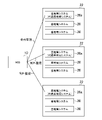
- FIG. 4 is an explanatory diagram schematically showing an example of classification of a base station system and exception monitoring;
- FIG. 3 is a functional block diagram showing an example of functions implemented in the NOS according to one embodiment of the present invention;
- FIG. 4 is a flow diagram showing an example of the flow of processing performed by the NOS according to one embodiment of the present invention;
- FIG. 4 is a flow diagram showing an example of the flow of processing performed by the NOS according to one embodiment of the present invention;
- FIG. 1 is a diagram showing an example of a communication system 1 according to one embodiment of the present invention.
- a communication system 1 includes a network operating system (NOS) 10, multiple core network systems 12, and multiple base station devices 14.
- NOS network operating system
- the NOS 10, core network system 12, and base station device 14 are connected to a computer network 16 such as the Internet.
- the core network system 12 is EPC (Evolved Packet Core) in the 4th generation mobile communication system (hereinafter referred to as 4G) and AMF (Access and Mobility) in the 5th generation mobile communication system (hereinafter referred to as 5G). Management Function), SMF (Session Management Function), UPF (User Plane Function), etc. It is a system equivalent to 5GC (5G Core Network).
- the core network system 12 according to this embodiment is implemented by a group of servers arranged in a plurality of data centers provided at various locations. A plurality of servers are arranged in each data center. Although two core network systems 12 are shown in FIG. 1, the number of core network systems 12 according to the present embodiment is not limited to two, and may be one or three or more. may be
- the base station device 14 is a computer system equipped with an antenna 14a, which corresponds to eNB (eNodeB) in 4G or gNB (NR base station) in 5G.
- the base station device 14 according to this embodiment includes one or more servers. Note that the base station device 14 may be implemented by a group of servers arranged in a data center.
- vDU virtual DU
- vCU virtual CU
- RAN Radio Access Network
- DUs and CUs which are components of the RAN in 5G, may be arranged in the base station device 14 or may be incorporated in a part of the core network system 12 .
- the base station system 20 when the RAN components are not incorporated in the core network system 12, the base station system 20 (see FIG. 3) in the following description refers to a system corresponding to the base station device 14. do. Also, in the case where the components of the RAN are incorporated in the core network system 12, the base station system 20 in the following description refers to a system including the base station device 14 and the relevant components of the core network system 12. and
- the NOS 10 is configured on a cloud platform, for example, and includes a processor 10a, a storage unit 10b, and a communication unit 10c, as shown in FIG.
- the processor 10a is a program-controlled device such as a microprocessor that operates according to programs installed in the NOS 10.
- the storage unit 10b is, for example, a storage element such as ROM or RAM, a solid state drive (SSD), a hard disk drive (HDD), or the like.
- the storage unit 10b stores programs and the like executed by the processor 10a.
- the communication unit 10c is, for example, a communication interface such as a NIC or a wireless LAN module.
- the communication unit 10 c exchanges data with the core network system 12 and the base station device 14 via the computer network 16 .
- the communication system 1 provides network services such as voice communication services and data communication services to users who use UE (User Equipment) 18 .
- network services such as voice communication services and data communication services to users who use UE (User Equipment) 18 .
- the network services provided in this embodiment are not limited to voice communication services and data communication services.
- the network service provided in this embodiment may be, for example, an IoT service.
- a container-type application execution environment such as Docker is installed in the servers arranged in the core network system 12 and the base station device 14, and containers are deployed to these servers. and can be operated.
- a cluster Kernetes cluster
- a container management tool such as Kubernetes may be constructed.
- a container-type application may then be executed on the constructed cluster.
- the network services provided in this embodiment are implemented by CNFs (Cloud-native Network Functions), which are container-based functional units.
- CNFs Cloud-native Network Functions
- the NOS 10 monitors multiple base station systems 20 included in the communication system 1 .
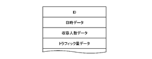
- the NOS 10 acquires parameter data indicating parameter values such as various performance indicators such as capacity and traffic volume in each base station system 20, the data structure of which is illustrated in FIG. 2, for example.
- each base station system 20 may sequentially transmit parameter data to the NOS 10 .
- the NOS 10 may then receive parameter data transmitted from each base station system 20 .
- the NOS 10 may sequentially access each base station system 20 and collect parameter data from that base station system 20 .
- the parameter data acquired from the base station system 20 includes an ID that is identification information of the base station system 20, date and time data indicating a specific date and time such as the number of people accommodated and traffic volume, Capacity data indicating the capacity of the station system 20, traffic volume data indicating the traffic volume of the base station system 20, and the like are included.
- the NOS 10 for example, at intervals of a predetermined unit time t1 (for example, 30 minutes), for each base station system 20, based on the parameter data received from the base station system 20, performs the following in the base station system 20:
- the traffic volume in unit time t1 is predicted.
- the NOS 10, for example, at intervals of a predetermined unit time t1, based on the number of people accommodated in the unit time t1, the amount of traffic, and the time associated with the unit time t1 (for example, the beginning or end of the unit time t1) may predict traffic volume.
- prediction of traffic volume may be executed using a trained machine learning model.
- the NOS 10 controls power consumption in each base station system 20 based on the predicted traffic volume.
- the optimal processor frequency for example, CPU frequency
- the NOS 10 may control the CPU frequency of the CPU operating in each base station system 20 so that the determined frequency is obtained for each base station system 20 .
- the NOS 10 may determine the optimum CPU frequency based on the parameter data, for example, by executing a predetermined power reduction algorithm.
- normal operation control operation control based on the predicted traffic volume as described above will be referred to as normal operation control. Also, monitoring (for example, acquisition of parameter data) executed in normal operation control is called normal monitoring.
- exceptional operation control is executed separately from the normal operation control described above.
- exceptional operation control in this embodiment, for example, as shown in FIG. It is classified into a base station system group 22 including the base station system 20 .
- the base station system group 22 classified in this manner is associated with the operating tendency of the base station system 20 .
- the base station system 20 may be classified based on the characteristics of the area covered by the base station system 20.
- the base station systems 20 may be classified based on the usage of the area covered by the base station system 20, daytime population density, nighttime population density, and the like. More specifically, for example, a plurality of base station systems 20 included in the communication system 1 may be a downtown area base station system group in which the area covered is a downtown area, or a residential area in which the area covered is a residential area. It may be classified into a base station system group, a business district base station system group covering a business district, and the like.
- the base station system 20 may be classified. For example, the base station systems 20 may be classified based on the user attributes (gender, age, generation, etc.) of users who communicate in the area covered by the base station systems 20 . Also, the base station system 20 may be classified based on multiple combinations of the above items.
- the plurality of base station systems 20 included in the communication system 1 may be classified into a base station system group 22 with heavy traffic during the daytime and a base station system group 22 with heavy traffic at night. Also, the plurality of base station systems 20 included in the communication system 1 may be classified into a base station system group 22 with heavy traffic on weekdays and a base station system group 22 with heavy traffic on holidays.
- the plurality of base station systems 20 included in the communication system 1 are divided into a base station system group 22 with a large amount of traffic during the daytime on weekdays, a group of base station systems 22 with a large amount of traffic during the nighttime on weekdays, and a group of base station systems 22 with a large amount of traffic during the daytime on holidays.
- a plurality of base station systems 20 included in the communication system 1 may be classified based on a combination of age, gender, and time period. For example, classification such as base station system group 22 with a large amount of daytime traffic by men in their twenties may be performed.
- a representative base station system 20a is selected from among the plurality of base station systems 20 included in the base station system group 22.
- a representative base station system 20 a may be randomly selected from among the plurality of base station systems 20 included in the base station system group 22 .
- the base station system 20 located in the geographical center among the plurality of base station systems 20 included in the base station system group 22 may be selected as the representative base station system 20a in the base station system group 22.
- the number of representative base station systems 20a selected in the base station system group 22 may be one or plural.
- the operating status of the representative base station system 20a is monitored in order to detect the occurrence of a predetermined exceptional situation.
- This monitoring is hereinafter referred to as exception monitoring.
- the CPU usage rate, power consumption, CPU frequency, traffic volume, and number of people accommodated in the area covered by the representative base station system 20a of the representative base station system 20a are monitored.
- exceptional monitoring monitoring of items other than the above-described normal monitoring items may be performed. For example, the value of a parameter such as a performance index not shown in the parameter data used for normal operation control (for example, the CPU utilization value) may be monitored.
- the base station system group 22 including the representative base station system 20a responds to the detection.
- Exceptional operation control which is predetermined operation control, is executed.
- the CPU usage rate of the representative base station system 20a exceeds a predetermined value.
- power consumption control may be performed to maximize power consumption in all base station systems 20 included in the base station system group 22 to which the representative base station system 20a belongs.
- the CPU frequency of all the base station systems 20 included in the base station system group 22 to which the representative base station system 20a belongs is set to the maximum CPU frequency that can be set in the base station system 20. may be controlled.
- exception monitoring is performed only for the representative base station system 20a. Then, in response to the occurrence of an exceptional situation in the representative base station system 20a, exceptional operation control is executed for at least one base station system 20 included in the base station system group 22 to which the representative base station system 20a belongs.
- FIG. 4 is a functional block diagram showing an example of functions implemented in the NOS 10 according to this embodiment. It should be noted that the NOS 10 according to the present embodiment need not implement all the functions shown in FIG. 4, and may implement functions other than the functions shown in FIG.
- the NOS 10 functionally includes, for example, a normal monitoring unit 30, a prediction unit 32, a classification unit 34, a selection unit 36, an exception monitoring unit 38, and an operation control unit 40. included.
- the normal monitoring unit 30 and the exception monitoring unit 38 are mainly implemented by the communication unit 10c.
- the prediction unit 32 and the selection unit 36 are mainly implemented by the processor 10a.
- the classification unit 34 is mainly implemented by the processor 10a and the storage unit 10b.
- the operation control unit 40 is mainly implemented by the processor 10a and the communication unit 10c.
- the above functions may be implemented by having the NOS 10, which is a computer, execute a program containing instructions corresponding to the above functions, which is installed in the NOS 10. Also, this program may be supplied to the NOS 10 via a computer-readable information storage medium such as an optical disk, magnetic disk, magnetic tape, or magneto-optical disk, or via the Internet or the like.
- a computer-readable information storage medium such as an optical disk, magnetic disk, magnetic tape, or magneto-optical disk, or via the Internet or the like.
- the normal monitoring unit 30 performs normal monitoring on a plurality of base station systems 20 in this embodiment, for example.
- the normal monitoring unit 30 acquires parameter data from each of the multiple base station systems 20 .
- the prediction unit 32 predicts the traffic volume in the area covered by each base station system 20 for each of the plurality of base station systems 20 .
- the classification unit 34 classifies a plurality of base station systems 20 included in the communication system 1 into a plurality of base station system groups 22 each associated with an operating tendency of the base station system 20 .
- the classification unit 34 may classify the multiple base station systems 20 included in the communication system 1 into multiple base station system groups 22 based on the characteristics of the areas covered by the base station systems 20 .
- the classification unit 34 shows map data indicating the geographical distribution of the core network system 12 and the base station devices 14, the usage of each district, the daytime population density and nighttime population density of each district, and the like. Statistical data or the like may be stored. Then, the classification unit 34 may classify the plurality of base station systems 20 into the plurality of base station system groups 22 based on data such as map data and statistical data.
- the classification unit 34 classifies the plurality of base station systems 20 included in the communication system 1 into a plurality of base station system groups 22 based on trends in traffic transitions or capacity transitions in areas covered by the base station systems 20. can be classified. In this case, the classifying unit 34 classifies the plurality of base station systems 20 included in the communication system 1 according to the traffic volume or the capacity of each time zone, day of the week, or day of the week in the area covered by the base station system 20. A plurality of base station system groups 22 may be classified based on trends.
- the classification unit 34 classifies the plurality of base station systems 20 included in the communication system 1 according to trends in traffic transitions or capacity transitions associated with user attributes of users who communicate in areas covered by the base station systems 20. Based on this, it may be classified into a plurality of base station system groups 22 .
- the classification unit 34 may accumulate communication histories of communications using the communication system 1 . Then, based on the accumulated communication history, the classification unit 34 may identify trends in traffic transition or capacity transition in the area covered by each base station system 20 for each base station system 20 . For example, based on the accumulated communication history, the classification unit 34, for each base station system 20, traffic volume or Capacity trends may be identified. Here, trends in traffic volume or capacity may be specified for each user attribute.
- the classifying unit 34 based on the parameter data acquired by the normal monitoring unit 30, the classifying unit 34 identifies trends in traffic transition or capacity transition in the area covered by the base station system 20 for each base station system 20. good too.
- the classification unit 34 classifies the plurality of base station systems 20 included in the communication system 1 into a plurality of base station system groups 22 based on the trend of traffic volume or number of people accommodated in this manner. good too.
- the selecting unit 36 selects the representative base station system 20a from among the multiple base station systems 20 included in the base station system group 22.
- the selection unit 36 may randomly select the representative base station system 20 a from among the plurality of base station systems 20 included in the base station system group 22 . Further, for example, the selection unit 36 selects the geographically most central base station system 20 among the plurality of base station systems 20 included in the base station system group 22 as the representative base station system 20a in the base station system group 22. may be elected.
- the selection unit 36 may select one representative base station system 20a for one base station system group 22, or may select a plurality of representative base station systems 20a.
- the exception monitoring unit 38 monitors the operation status of the representative base station system 20a among the plurality of base station systems 20 included in the base station system group 22 associated with the operation trend of the base station system 20. do.
- the monitoring by the exception monitoring unit 38 is, for example, the exception monitoring described above.
- the operation control unit 40 executes normal operation control for each of the plurality of base station systems 20 based on the amount of traffic predicted for that base station system 20 .
- the operation control unit 40 includes at least one base station included in the base station system group 22 to which the representative base station system 20a belongs, which includes a base station system 20 different from the representative base station system 20a.
- Exceptional operation control which is operation control according to the operation status of the representative base station system 20a, is executed for the system 20.
- the operation control unit 40 may execute exceptional operation control when the value indicating the operation status of the representative base station system 20a satisfies a predetermined condition. For example, the operation control unit 40 may execute exceptional operation control in response to the operating status of the representative base station system 20a exceeding a predetermined height. Here, when normal operation control is being executed, exceptional operation control may be executed in response to the height of the operational status of the representative base station system 20a exceeding a predetermined height. .
- the operation control unit 40 may transmit a control signal related to the operation control to the base station system 20 that is the target of operation control. Then, the base station system 20 that receives the control signal may perform operation control according to the control signal.
- the operation control unit 40 may perform power consumption control such as control to change the CPU frequency.
- the operation control unit 40 when the value indicating the CPU usage rate of the representative base station system 20a monitored by the exception monitoring unit 38 exceeds a predetermined threshold, A base station system group 22 including the base station system 20a may be identified. Then, the operation control unit 40 may perform operation control to increase the CPU frequency for at least one base station system 20 included in the identified base station system group 22 . For example, the operation control unit 40 performs operation control to set at least one base station system 20 included in the specified base station system group 22 to the highest CPU frequency that can be set in the base station system 20. may In this way, the CPU frequencies of the CPUs of the servers included in the base station system 20 whose operation is to be controlled are changed.
- the operating status monitored by the exception monitoring unit 38 is not limited to the CPU usage rate as in the above example. For example, CPU frequency, power consumption, capacity, traffic volume, etc. may be monitored.
- the operation control unit 40 may execute the exceptional operation control. For example, when the actual traffic volume is greater than the predicted traffic volume by a predetermined amount or more, or when the actual traffic volume is greater than or equal to the predicted traffic volume by a predetermined amount or more, exceptional operation control is executed. You may do so.
- the prediction unit 32 waits until prediction timing occurs at intervals of a predetermined unit time t1 (S101).
- the prediction unit 32 predicts the traffic volume in the next unit time t1 based on the parameter data acquired in the most recent unit time t1 for each of the plurality of base station systems 20 (S102). .
- the operation control unit 40 determines the optimum CPU frequency for each of the plurality of base station systems 20 based on the amount of traffic predicted in the processing shown in S102 (S103).
- the operation control unit 40 may store in advance a table in which the traffic volume is associated with the optimum CPU frequency, and the optimum CPU frequency may be determined based on the table.
- the optimal CPU frequency may be determined using a trained machine learning model.
- the operation control unit 40 executes normal operation control to control the CPU of the server included in the base station system 20 to the CPU frequency determined in the processing shown in S102. Then (S104), the process returns to S101.
- the exception monitoring unit 38 monitors the operation status of the representative base station system 20a (S201).
- S201 for example, the CPU usage rate of the representative base station system 20a is monitored.
- the operation control unit 40 controls the representative base station system 20a in which the occurrence of the predetermined exception has been detected. is specified (S202). For example, when the value indicating the CPU usage rate of the representative base station system 20a exceeds a predetermined threshold, the base station system group 22 including the representative base station system 20a is identified.
- the operation control unit 40 executes exceptional operation control for all base station systems 20 included in the base station system group 22 specified in the process shown in S202 (S203), and returns to the process shown in S201.
- exceptional operation control for all the base station systems 20 included in the base station system group 22 specified in the processing shown in S202, control is performed so that the CPU of the server included in the base station system 20 has the highest CPU frequency that can be set. Exceptional operation control is performed. In the present embodiment, for example, exceptional operation control is also executed for the representative base station system 20a included in the base station system group 22 specified in the processing shown in S202.
- Exception monitoring performed in the process shown in S201 may be performed, for example, at intervals of a predetermined time t2 (eg, 5 minutes).
- the representative base station system 20a may sequentially (for example, at intervals of 5 minutes) transmit to the NOS 10 CPU usage rate data indicating the CPU usage rate of the representative base station system 20a.
- the NOS 10 may receive the CPU utilization data transmitted from the representative base station system 20a.
- the NOS 10 may access the representative base station system 20a sequentially (for example, at intervals of 5 minutes) and collect CPU utilization data indicating the CPU utilization from the representative base station system 20a.
- the representative base station system 20a may transmit an exception notification to the NOS 10 when the value indicating the CPU usage rate of the representative base station system 20a exceeds a predetermined threshold. Then, the exception monitoring unit 38 may receive the exception notification. In this case, receiving the exception notification corresponds to detecting the occurrence of the above-described exception situation. Then, the processes shown in S202 and S203 described above may be executed in response to the reception of the exception notification.
- normal monitoring may be performed only for the representative base station system 20a. Then, for at least one base station system 20 included in the base station system group 22 to which the representative base station system 20a belongs, including the base station system 20 different from the representative base station system 20a, the representative base station system 20a Normal operation control may be performed according to the predicted traffic volume. In this way, not only exceptional monitoring but also normal monitoring is not performed for the base station system 20 other than the representative base station system 20a, so that the monitoring load can be further reduced.
- the operation control for another base station system 20 according to the operation status of the representative base station system 20a may be operation control for lowering power consumption (power saving control) such as operation control for lowering the CPU frequency. .
- the normal operation control and the exceptional operation control according to this embodiment are not limited to the control for changing the CPU frequency as in the above example.
- operation control such as scale-out or scale-down of servers included in the base station system 20 may be executed.
- some or all of the functions shown in FIG. 4 may be performed by the base station system 20.
Landscapes
- Engineering & Computer Science (AREA)
- Computer Networks & Wireless Communication (AREA)
- Signal Processing (AREA)
- Mobile Radio Communication Systems (AREA)
Abstract
基地局システムの動作制御を行う際の監視負担を低減できる制御システム及び制御方法を提供する。例外監視部(34)は、基地局システムの稼働傾向に対応付けられる基地局システム群に含まれる複数の基地局システムのうちの代表基地局システムの稼働状況を監視する。動作制御部(36)は、代表基地局システムとは異なる基地局システムを含む、基地局システム群に含まれる少なくとも1つの基地局システムに対して、代表基地局システムの稼働状況に応じた動作制御を実行する。
Description
本発明は、制御システム及び制御方法に関する。
特許文献1には、急激なトラフィックの増加が生じた部分通信エリアの仮想ノードの稼働数を増大させることで、リソース不足のために通信速度が低下することを抑制することが記載されている。また、特許文献1には、急激なトラフィックの減少が生じた部分通信エリアの仮想ノードの稼働数を減少させることで、サーバの消費電力が増大することを抑制することが記載されている。
特許文献1に記載の技術を用いて基地局システムの動作制御を行う場合、それぞれの基地局システムについて、当該基地局システムがカバーするエリアのトラフィックを監視する必要があるため、基地局システムの数が多い場合は、監視負担が大きい。
本発明は上記実情に鑑みてなされたものであって、その目的の一つは、基地局システムの動作制御を行う際の監視負担を低減できる制御システム及び制御方法を提供することにある。
上記課題を解決するために、本発明に係る制御システムは、基地局システムの稼働傾向に対応付けられる基地局システム群に含まれる複数の基地局システムのうちの代表基地局システムの稼働状況を監視する監視手段と、前記代表基地局システムとは異なる前記基地局システムを含む、前記基地局システム群に含まれる少なくとも1つの前記基地局システムに対して、前記代表基地局システムの稼働状況に応じた動作制御を実行する制御手段と、を含む。
本発明の一態様では、前記制御手段は、前記代表基地局システムの稼働状況を示す値が所定の条件を満たしたことに応じて、前記動作制御を実行する。
また、本発明の一態様では、前記制御手段は、前記代表基地局システムの稼働状況の高さが所定の高さを超えたことに応じて、前記動作制御を実行する。
あるいは、前記基地局システム群に含まれる複数の基地局システムのそれぞれについて、当該基地局システムがカバーするエリアにおけるトラフィック量を予測する予測手段、をさらに含み、前記基地局システム群に含まれる前記複数の基地局システムのそれぞれに対して当該基地局システムについて予測されるトラフィック量に基づく通常動作制御が実行されている際に、前記代表基地局システムの稼働状況の高さが所定の高さを超えたことに応じて、前記制御手段は、前記代表基地局システムとは異なる前記基地局システムを含む、前記基地局システム群に含まれる少なくとも1つの前記基地局システムに対して、前記代表基地局システムの稼働状況に応じた例外動作制御を実行する。
あるいは、前記基地局システム群に含まれる前記複数の基地局システムのそれぞれについて、当該基地局システムがカバーするエリアにおけるトラフィック量を予測する予測手段、をさらに含み、前記基地局システム群に含まれる前記複数の基地局システムのそれぞれに対して当該基地局システムについて予測されるトラフィック量に基づく通常動作制御が実行されている際に、前記代表基地局システムの実際のトラフィック量と予測されるトラフィック量との違いが所定の条件を満足したことに応じて、前記制御手段は、前記代表基地局システムとは異なる前記基地局システムを含む、前記基地局システム群に含まれる少なくとも1つの前記基地局システムに対して、前記代表基地局システムの稼働状況に応じた例外動作制御を実行する。
また、本発明の一態様では、複数の基地局システムを、それぞれ基地局システムの稼働傾向に対応付けられる複数の基地局システム群に分類する分類手段、をさらに含む。
この態様では、前記分類手段は、前記複数の前記基地局システムを、前記基地局システムがカバーするエリアの特性に基づいて、複数の基地局システム群に分類してもよい。
また、前記分類手段は、前記複数の前記基地局システムを、前記基地局システムがカバーするエリアにおけるトラフィック推移又は収容人数推移の傾向に基づいて、複数の基地局システム群に分類してもよい。
この場合、前記分類手段は、前記複数の前記基地局システムを、前記基地局システムがカバーするエリアにおける時間帯毎、曜日毎、又は、曜日帯毎のトラフィック量又は収容人数の傾向に基づいて、複数の基地局システム群に分類してもよい。
また、前記分類手段は、前記複数の前記基地局システムを、前記基地局システムがカバーするエリアで通信を行うユーザのユーザ属性に対応付けられるトラフィック推移又は収容人数推移の傾向に基づいて、複数の基地局システム群に分類してもよい。
また、本発明の一態様では、前記基地局システム群に含まれる前記複数の前記基地局システムのうちから、前記代表基地局システムを選出する選出手段、をさらに含む。
また、本発明の一態様では、前記制御手段は、消費電力制御を実行する。
また、本発明に係る制御方法は、基地局システムの稼働傾向に対応付けられる基地局システム群に含まれる複数の基地局システムのうちの代表基地局システムの稼働状況を監視するステップと、前記代表基地局システムとは異なる前記基地局システムを含む、前記基地局システム群に含まれる少なくとも1つの前記基地局システムに対して、前記代表基地局システムの稼働状況に応じた動作制御を実行するステップと、を含む。
以下、本発明の一実施形態について図面に基づき詳細に説明する。
図1は、本発明の一実施形態に係る通信システム1の一例を示す図である。図1に示すように、本実施形態に係る通信システム1には、ネットワークオペレーティングシステム(NOS)10、複数のコアネットワークシステム12、及び、複数の基地局装置14が含まれる。NOS10、コアネットワークシステム12、基地局装置14は、インターネット等のコンピュータネットワーク16に接続されている。
コアネットワークシステム12は、第4世代移動通信システム(以下、4Gと呼ぶ。)におけるEPC(Evolved Packet Core)や、第5世代移動通信システム(以下、5Gと呼ぶ。)における、AMF(Access and Mobility Management Function)、SMF(Session Management Function)、UPF(User Plane Function)等を含む5GC(5G Core Network)に相当するシステムである。本実施形態に係るコアネットワークシステム12は、様々なロケーションに設けられた複数のデータセンタに配置されたサーバ群によって実装されている。各データセンタには、複数のサーバが配置されている。なお、図1には2つのコアネットワークシステム12が示されているが、本実施形態に係るコアネットワークシステム12の数は2つには限定されず、1つであってもよいし3つ以上であってもよい。
基地局装置14は、4GにおけるeNB(eNodeB)や、5GにおけるgNB(NR基地局)に相当する、アンテナ14aを備えたコンピュータシステムである。本実施形態に係る基地局装置14には、1又は複数のサーバが含まれる。なお、基地局装置14がデータセンタに配置されたサーバ群によって実装されていても構わない。
また、4GにおけるRAN(Radio Access Network)の構成要素であるvDU(virtual DU)やvCU(virtual CU)は、基地局装置14に配置されてもよいしコアネットワークシステム12の一部に組み込まれていてもよい。また、5GにおけるRANの構成要素であるDUやCUについても同様に、基地局装置14に配置されてもよいしコアネットワークシステム12の一部に組み込まれていてもよい。
本実施形態において、RANの構成要素がコアネットワークシステム12に組み込まれていない場合については、以下の説明における基地局システム20(図3参照)は、基地局装置14に相当するシステムを指すこととする。また、RANの構成要素がコアネットワークシステム12に組み込まれている場合については、以下の説明における基地局システム20は、基地局装置14とコアネットワークシステム12の当該構成要素とを含むシステムを指すこととする。
本実施形態に係るNOS10は、例えば、クラウド基盤上に構成されており、図1に示すように、プロセッサ10a、記憶部10b、通信部10c、が含まれる。プロセッサ10aは、NOS10にインストールされるプログラムに従って動作するマイクロプロセッサ等のプログラム制御デバイスである。記憶部10bは、例えばROMやRAM等の記憶素子や、ソリッドステートドライブ(SSD)、ハードディスクドライブ(HDD)などである。記憶部10bには、プロセッサ10aによって実行されるプログラムなどが記憶される。通信部10cは、例えば、NICや無線LANモジュールなどといった通信インタフェースである。通信部10cは、コンピュータネットワーク16を介して、コアネットワークシステム12、基地局装置14との間でデータを授受する。
本実施形態に係る通信システム1によって、音声通信サービスやデータ通信サービス等のネットワークサービスが、UE(User Equipment)18を利用するユーザに提供されることとなる。
なお、本実施形態において提供されるネットワークサービスは音声通信サービスやデータ通信サービスには限定されない。本実施形態において提供されるネットワークサービスは、例えば、IoTサービスであっても構わない。
また、本実施形態では、コアネットワークシステム12や基地局装置14に配置されているサーバには、ドッカー(Docker)などのコンテナ型のアプリケーション実行環境がインストールされており、これらのサーバにコンテナをデプロイして稼働させることができるようになっている。これらのサーバにおいて、クバネテス(Kubernetes)等のコンテナ管理ツールによって管理されるクラスタ(クバネテスクラスタ)が構築されていてもよい。そして、構築されたクラスタ上でコンテナ型のアプリケーションが実行されてもよい。
そして、本実施形態において提供されるネットワークサービスは、コンテナベースの機能ユニットであるCNF(Cloud-native Network Function)によって実装される。
本実施形態では例えば、NOS10が、通信システム1に含まれる複数の基地局システム20を監視する。当該監視において、NOS10は、例えば、図2にデータ構造が例示されている、各基地局システム20における収容人数やトラフィック量などといった各種の性能指標等のパラメータの値を示すパラメータデータを取得する。ここで例えば、それぞれの基地局システム20が、逐次、パラメータデータをNOS10に送信してもよい。そして、NOS10が、各基地局システム20から送信されるパラメータデータを受信してもよい。あるいは、NOS10が、逐次、それぞれの基地局システム20にアクセスして、当該基地局システム20からパラメータデータを収集してもよい。
基地局システム20から取得されるパラメータデータには、例えば、図2に示すように、当該基地局システム20の識別情報であるID、収容人数やトラフィック量などの特定日時を示す日時データ、当該基地局システム20の収容人数を示す収容人数データ、当該基地局システム20のトラフィック量を示すトラフィック量データ、などが含まれる。
そして、NOS10は、例えば、所定の単位時間t1(例えば、30分)間隔で、各基地局システム20について、当該基地局システム20から受信したパラメータデータに基づいて、当該基地局システム20における次の単位時間t1におけるトラフィック量を予測する。NOS10は、例えば、所定の単位時間t1間隔で、当該単位時間t1における収容人数、トラフィック量、及び、当該単位時間t1に対応付けられる時刻(例えば、当該単位時間t1の始期又は終期)に基づいて、トラフィック量を予測してもよい。ここで、学習済の機械学習モデルを用いて、トラフィック量の予測が実行されてもよい。
そして、NOS10は、各基地局システム20について、予測されるトラフィック量に基づいて、当該基地局システム20における電力消費量を制御する。ここで例えば、予測されるトラフィック量に見合った節電(省電力での動作)が実行されるよう、当該基地局システム20において最適なプロセッサの周波数(例えば、CPU周波数)が決定されてもよい。そして、NOS10は、各基地局システム20について、決定される周波数となるよう、当該基地局システム20において動作するCPUのCPU周波数を制御してもよい。
ここでNOS10は、例えば、所定の電力削減アルゴリズムを実行することで、パラメータデータに基づいて、最適なCPU周波数を決定してもよい。
以下、以上で説明したような、予測されるトラフィック量に基づく動作制御を、通常動作制御と呼ぶこととする。また、通常動作制御において実行される監視(例えば、パラメータデータの取得)を、通常監視と呼ぶこととする。
本実施形態では例えば、以上で説明した通常動作制御とは別に、例外動作制御が実行される。例外動作制御を実行するために、本実施形態では例えば、図3に示すように、通信システム1に含まれる複数の基地局システム20が、基地局システム20の稼働傾向に基づいて、それぞれ複数の基地局システム20を含む基地局システム群22に分類される。このようにして分類された基地局システム群22は、基地局システム20の稼働傾向に対応付けられるものとなる。
ここで例えば、基地局システム20がカバーするエリアの特性に基づいて基地局システム20が分類されてもよい。
例えば、基地局システム20がカバーしているエリアの用途や昼間人口密度や夜間人口密度などに基づいて、基地局システム20が分類されてもよい。より具体的には例えば、通信システム1に含まれる複数の基地局システム20が、カバーしているエリアが繁華街である繁華街基地局システム群、カバーしているエリアが住宅街である住宅地基地局システム群、カバーしているエリアがビジネス街であるビジネス街基地局システム群、などに分類されてもよい。
また、基地局システム20がカバーするエリアにおけるトラフィック推移又は収容人数推移の傾向(例えば、時間帯毎、曜日毎、又は、曜日帯毎のトラフィック量又は収容人数の傾向)に基づいて、基地局システム20が分類されてもよい。例えば、基地局システム20がカバーするエリアで通信を行うユーザのユーザ属性(性別、年齢、年代など)に基づいて、基地局システム20が分類されてもよい。また、以上の項目のうちの複数の組合せに基づいて、基地局システム20が分類されてもよい。
例えば、通信システム1に含まれる複数の基地局システム20が、昼間のトラフィック量が多い基地局システム群22と夜間のトラフィック量が多い基地局システム群22とに分類されてもよい。また、通信システム1に含まれる複数の基地局システム20が、平日のトラフィック量が多い基地局システム群22と休日のトラフィック量が多い基地局システム群22とに分類されてもよい。
また、通信システム1に含まれる複数の基地局システム20が、平日の昼間のトラフィック量が多い基地局システム群22、平日の夜間のトラフィック量が多い基地局システム群22、休日の昼間のトラフィック量が多い基地局システム群22、休日の夜間のトラフィック量が多い基地局システム群22、に分類されてもよい。
また、例えば、通信システム1に含まれる複数の基地局システム20が、年代と性別と時間帯との組合せに基づいて分類されてもよい。例えば、20代の男性による昼間のトラフィック量が多い基地局システム群22、などのような分類が行われてもよい。
そして、本実施形態では例えば、それぞれの基地局システム群22について、当該基地局システム群22に含まれる複数の基地局システム20のうちから、代表基地局システム20aが選出される。ここで例えば、基地局システム群22に含まれる複数の基地局システム20のうちからランダムに代表基地局システム20aが選出されてもよい。また例えば、基地局システム群22に含まれる複数の基地局システム20のうち地理的に最も中心にある基地局システム20が、当該基地局システム群22における代表基地局システム20aとして選出されてもよい。なお、基地局システム群22において選出される代表基地局システム20aは1つであってもよいし複数であってもよい。
そして、本実施形態では、所定の例外状況の発生を検出するために、代表基地局システム20aの稼働状況の監視が行われる。以下、この監視を例外監視と呼ぶこととする。ここでは例えば、代表基地局システム20aのCPU使用率、電力消費量、CPU周波数、トラフィック量、当該基地局システム20でカバーされるエリアにおける収容人数などが監視される。例外監視においては、上述の通常監視の監視項目ではない項目の監視が実行されてもよい。例えば、通常動作制御に用いられるパラメータデータには示されていない性能指標等のパラメータの値(例えば、CPU使用率の値)が監視されてもよい。
そして、本実施形態では、例外監視において代表基地局システム20aにおいて所定の例外状況が発生したことが検出されたら、当該検出に応じて、当該代表基地局システム20aが含まれる基地局システム群22に対して所定の動作制御である例外動作制御が実行される。
例えば、代表基地局システム20aのCPU使用率が所定値を超えた状況が発生したとする。この場合、例えば、当該代表基地局システム20aが属する基地局システム群22に含まれるすべての基地局システム20において消費電力量が最大となる消費電力制御が実行されてもよい。より具体的には例えば、当該代表基地局システム20aが属する基地局システム群22に含まれるすべての基地局システム20のCPU周波数が、当該基地局システム20において設定可能な最高のCPU周波数となるよう制御されてもよい。
なお、所定の例外状況が発生した代表基地局システム20aが属する基地局システム群22に含まれるすべての基地局システム20について、画一的な例外動作制御が行われる必要はない。例えば所定の例外状況が発生した代表基地局システム20aが属する基地局システム群22に含まれる基地局システム20のそれぞれについて、当該基地局システム20の稼働状況に応じた例外動作制御が実行されてもよい。また、所定の例外状況が発生した代表基地局システム20aが属する基地局システム群22に含まれる複数の基地局システム20のうちの一部だけに対して例外動作制御が実行されるようにしてもよい。
例えば通常時に基地局システム20において省電力での動作が実行されている際に、トラフィック量の突発的な増加が発生し、CPU使用率が突発的に高くなることがある。このような場合は、突発的に増加したトラフィック量を処理できるよう省電力での動作を直ちに解除することが望ましい。
ここで、トラフィック量の突発的な増加などの例外状況の発生の監視をすべての基地局システム20に対して行うとなると監視負担が大きい。
本実施形態では、上述のように、例外監視は代表基地局システム20aだけに対してしか行われない。そして、代表基地局システム20aにおける例外状況の発生に応じて、当該代表基地局システム20aが属する基地局システム群22に含まれる少なくとも1つの基地局システム20に対する例外動作制御が実行される。
このようにして、本実施形態によれば、基地局システム20の動作制御を行う際の監視負担を低減できることとなる。
以下、上述の動作制御を中心に、本実施形態に係るNOS10の機能、及び、NOS10で実行される処理について、さらに説明する。
図4は、本実施形態に係るNOS10で実装される機能の一例を示す機能ブロック図である。なお、本実施形態に係るNOS10で、図4に示す機能のすべてが実装される必要はなく、また、図4に示す機能以外の機能が実装されていても構わない。
図4に示すように、本実施形態に係るNOS10には、機能的には例えば、通常監視部30、予測部32、分類部34、選出部36、例外監視部38、動作制御部40、が含まれる。
通常監視部30、例外監視部38は、通信部10cを主として実装される。予測部32、選出部36は、プロセッサ10aを主として実装される。分類部34は、プロセッサ10a及び記憶部10bを主として実装される。動作制御部40は、プロセッサ10a及び通信部10cを主として実装される。
以上の機能は、コンピュータであるNOS10にインストールされた、以上の機能に対応する指令を含むプログラムをNOS10で実行することにより実装されてもよい。また、このプログラムは、例えば、光ディスク、磁気ディスク、磁気テープ、光磁気ディスク等のコンピュータ読み取り可能な情報記憶媒体を介して、あるいは、インターネットなどを介してNOS10に供給されてもよい。
通常監視部30は、本実施形態では例えば、複数の基地局システム20に対して通常監視を実行する。例えば、通常監視部30は、複数の基地局システム20のそれぞれから、パラメータデータを取得する。
予測部32は、本実施形態では例えば、複数の基地局システム20のそれぞれについて、当該基地局システム20がカバーするエリアにおけるトラフィック量を予測する。
分類部34は、本実施形態では例えば、通信システム1に含まれる複数の基地局システム20を、それぞれ基地局システム20の稼働傾向に対応付けられる複数の基地局システム群22に分類する。
分類部34は、通信システム1に含まれる複数の基地局システム20を、基地局システム20がカバーするエリアの特性に基づいて、複数の基地局システム群22に分類してもよい。この場合、例えば、分類部34に、コアネットワークシステム12や基地局装置14の地理的な分布や各地区の用途を示す地図データや、各地区の昼間人口密度や夜間人口密度などが示されている統計データなどが記憶されていてもよい。そして、分類部34が、地図データや統計データなどのデータに基づいて、複数の基地局システム20を、複数の基地局システム群22に分類してもよい。
また、分類部34は、通信システム1に含まれる複数の基地局システム20を、基地局システム20がカバーするエリアにおけるトラフィック推移又は収容人数推移の傾向に基づいて、複数の基地局システム群22に分類してもよい。この場合、分類部34は、通信システム1に含まれる複数の基地局システム20を、基地局システム20がカバーするエリアにおける時間帯毎、曜日毎、又は、曜日帯毎のトラフィック量又は収容人数の傾向に基づいて、複数の基地局システム群22に分類してもよい。
また、分類部34は、通信システム1に含まれる複数の基地局システム20を、基地局システム20がカバーするエリアで通信を行うユーザのユーザ属性に対応付けられるトラフィック推移又は収容人数推移の傾向に基づいて、複数の基地局システム群22に分類してもよい。
例えば、分類部34に、通信システム1を利用した通信における通信履歴が蓄積されるようにしてもよい。そして、分類部34が、蓄積された通信履歴に基づいて、それぞれの基地局システム20について、当該基地局システム20がカバーするエリアにおけるトラフィック推移又は収容人数推移の傾向を特定してもよい。例えば、分類部34が、蓄積された通信履歴に基づいて、それぞれの基地局システム20について、当該基地局システム20がカバーするエリアにおける時間帯毎、曜日毎、又は、曜日帯毎のトラフィック量又は収容人数の傾向を特定してもよい。ここで、ユーザ属性別に、トラフィック量又は収容人数の傾向が特定されてもよい。
また、分類部34は、通常監視部30が取得するパラメータデータに基づいて、それぞれの基地局システム20について、当該基地局システム20がカバーするエリアにおけるトラフィック推移又は収容人数推移の傾向を特定してもよい。
そして、分類部34は、このようにして特定されるトラフィック量又は収容人数の傾向に基づいて、通信システム1に含まれる複数の基地局システム20を、複数の基地局システム群22に分類してもよい。
選出部36は、本実施形態では例えば、複数の基地局システム群22のそれぞれについて、当該基地局システム群22に含まれる複数の基地局システム20のうちから、代表基地局システム20aを選出する。
選出部36は、基地局システム群22に含まれる複数の基地局システム20のうちからランダムに代表基地局システム20aを選出してもよい。また例えば、選出部36は、基地局システム群22に含まれる複数の基地局システム20のうち地理的に最も中心にある基地局システム20を、当該基地局システム群22における代表基地局システム20aとして選出してもよい。
なお、選出部36は、1つの基地局システム群22について、1つの代表基地局システム20aを選出してもよいし、複数の代表基地局システム20aを選出してもよい。
例外監視部38は、本実施形態では例えば、基地局システム20の稼働傾向に対応付けられる基地局システム群22に含まれる複数の基地局システム20のうちの代表基地局システム20aの稼働状況を監視する。例外監視部38による監視は、例えば、上述した例外監視である。
動作制御部40は、本実施形態では例えば、複数の基地局システム20のそれぞれに対して、当該基地局システム20について予測されるトラフィック量に基づく通常動作制御を実行する。
また、動作制御部40は、本実施形態では例えば、代表基地局システム20aとは異なる基地局システム20を含む、当該代表基地局システム20aが属する基地局システム群22に含まれる少なくとも1つの基地局システム20に対して、代表基地局システム20aの稼働状況に応じた動作制御である例外動作制御を実行する。
動作制御部40は、代表基地局システム20aの稼働状況を示す値が所定の条件を満たしたことに応じて、例外動作制御を実行してもよい。例えば、動作制御部40は、代表基地局システム20aの稼働状況の高さが所定の高さを超えたことに応じて、例外動作制御を実行してもよい。ここで、通常動作制御が実行されている際に、代表基地局システム20aの稼働状況の高さが所定の高さを超えたことに応じて、例外動作制御が実行されるようにしてもよい。
また、代表基地局システム20aの稼働状況の高さが所定の高さを超えたことに応じて、当該代表基地局システム20aが属する基地局システム群22に含まれるすべての基地局システム20に対して例外動作制御が実行されてもよい。また、代表基地局システム20aの稼働状況の高さが所定の高さを超えたことに応じて、当該代表基地局システム20aが属する基地局システム群22に含まれる一部の基地局システム20に対して例外動作制御が実行されてもよい。
通常動作制御や例外動作制御において、例えば、動作制御部40が、動作制御の対象となる基地局システム20に対して当該動作制御に係る制御信号を送信してもよい。そして、当該制御信号を受信した基地局システム20が、当該制御信号に応じた動作制御を実行してもよい。
また、上述のように、通常動作制御や例外動作制御において、動作制御部40が、CPU周波数を変更させる制御などといった、消費電力制御を実行してもよい。
例えば、上述の例のように、動作制御部40は、例外監視部38によって監視されている代表基地局システム20aのCPU使用率を示す値が所定の閾値を超えたことに応じて、当該代表基地局システム20aが含まれる基地局システム群22を特定してもよい。そして、動作制御部40は、特定される基地局システム群22に含まれる少なくとも1つの基地局システム20に対して、CPU周波数を上げる動作制御を実行してもよい。例えば、動作制御部40は、特定される基地局システム群22に含まれる少なくとも1つの基地局システム20に対して、当該基地局システム20において設定可能な最高のCPU周波数にさせる動作制御を実行してもよい。このようにして、動作制御の対象となる基地局システム20に含まれるサーバ群のCPUのCPU周波数が変更されることとなる。
なお、例外監視部38によって監視される稼働状況は上述の例のようなCPU使用率には限定されない。例えば、CPU周波数、電力消費量、収容人数、トラフィック量、などが監視されてもよい。
また、本実施形態において、上述の通常動作制御が実行されている際に、代表基地局システム20aの実際のトラフィック量と予測されるトラフィック量との違いが所定の条件を満足したことに応じて、動作制御部40が例外動作制御を実行してもよい。例えば、実際のトラフィック量が予測されるトラフィック量よりも所定量以上大きくなった、あるいは、実際のトラフィック量が予測されるトラフィック量の所定倍以上となった際に、例外動作制御が実行されるようにしてもよい。
ここで、本実施形態に係るNOS10で行われる通常動作制御に係る処理の流れの一例を、図5に例示するフロー図を参照しながら説明する。
まず、予測部32は、所定の単位時間t1間隔で発生する予測タイミングが到来するまで待機する(S101)。
予測タイミングが到来すると、予測部32は、複数の基地局システム20のそれぞれについて、直近の単位時間t1で取得されたパラメータデータに基づいて、次の単位時間t1におけるトラフィック量を予測する(S102)。
そして、動作制御部40が、複数の基地局システム20のそれぞれについて、S102に示す処理で予測されたトラフィック量に基づいて、最適なCPU周波数を決定する(S103)。ここで例えば、動作制御部40には予めトラフィック量と最適なCPU周波数とを対応付けたテーブルが記憶されており、当該テーブルに基づいて最適なCPU周波数を決定されてもよい。また、学習済の機械学習モデルを用いて、最適なCPU周波数が決定されてもよい。
そして、動作制御部40が、複数の基地局システム20のそれぞれについて、当該基地局システム20に含まれるサーバのCPUがS102に示す処理で決定されたCPU周波数となるよう制御する通常動作制御を実行して(S104)、S101に示す処理に戻る。
次に、本実施形態に係るNOS10で行われる例外動作制御に係る処理の流れの一例を、図6に例示するフロー図を参照しながら説明する。本処理例に示す処理においては、複数の代表基地局システム20aのそれぞれについて、例外監視部38による稼働状況の監視が行われていることとする。
まず、例外監視部38が、代表基地局システム20aの稼働状況を監視する(S201)。S201に示す処理では、例えば、代表基地局システム20aのCPU使用率が監視される。
そして、例外監視部38によって、監視中の稼働状況における所定の例外状況の発生が検出されたことに応じて、動作制御部40は、所定の例外状況の発生が検出された代表基地局システム20aが含まれる基地局システム群22を特定する(S202)。例えば、代表基地局システム20aのCPU使用率を示す値が所定の閾値を超えたことに応じて、当該代表基地局システム20aが含まれる基地局システム群22が特定される。
そして、動作制御部40が、S202に示す処理で特定された基地局システム群22に含まれるすべての基地局システム20について、例外動作制御を実行して(S203)、S201に示す処理に戻る。例えば、S202に示す処理で特定された基地局システム群22に含まれるすべての基地局システム20について、当該基地局システム20に含まれるサーバのCPUが設定可能な最高のCPU周波数となるよう制御する例外動作制御が実行される。本実施形態では例えば、S202に示す処理で特定された基地局システム群22に含まれる代表基地局システム20aに対しても、例外動作制御が実行される。
S201に示す処理で実行される例外監視は、例えば、所定時間t2(例えば、5分)間隔で実行されてもよい。ここで例えば、代表基地局システム20aが、逐次(例えば5分間隔で)、当該代表基地局システム20aのCPU使用率を示すCPU使用率データをNOS10に送信してもよい。そして、NOS10が、代表基地局システム20aから送信される当該CPU使用率データを受信してもよい。あるいは、NOS10が、逐次(例えば5分間隔で)、代表基地局システム20aにアクセスして、当該代表基地局システム20aからCPU使用率を示すCPU使用率データを収集してもよい。
あるいは、代表基地局システム20aのCPU使用率を示す値が所定の閾値を超えたことに応じて、当該代表基地局システム20aが例外通知をNOS10に送信してもよい。そして、例外監視部38が当該例外通知を受信してもよい。この場合、例外通知の受信が、上述の例外状況の発生の検出に相当する。そして、当該例外通知の受信に応じて、上述のS202及びS203に示す処理が実行されるようにしてもよい。
なお、本発明は上述の実施形態に限定されるものではない。
例えば、上述の通常動作制御でも、代表基地局システム20aだけに対して通常監視が行われるようにしてもよい。そして、代表基地局システム20aとは異なる基地局システム20を含む、当該代表基地局システム20aが属する基地局システム群22に含まれる少なくとも1つの基地局システム20に対して、代表基地局システム20aについて予測されるトラフィック量に応じた通常動作制御が実行されてもよい。このようにすれば、代表基地局システム20aではない基地局システム20については例外監視だけでなく通常監視も行われないため、監視負担はさらに低減できることとなる。
また、代表基地局システム20aの稼働状況に応じた、別の基地局システム20に対する動作制御は、CPU周波数を下げる動作制御などといった消費電力を下げる動作制御(省電力制御)であっても構わない。
また、本実施形態に係る通常動作制御や例外動作制御は、上述の例のようなCPU周波数を変更させる制御には限定されない。例えば、例外動作制御において、基地局システム20に含まれるサーバのスケールアウト、あるいは、スケールダウンなどの動作制御が実行されてもよい。
また、例えば、図4に示されている機能の一部又は全部が、基地局システム20で実行されてもよい。
Claims (13)
- 基地局システムの稼働傾向に対応付けられる基地局システム群に含まれる複数の基地局システムのうちの代表基地局システムの稼働状況を監視する監視手段と、
前記代表基地局システムとは異なる前記基地局システムを含む、前記基地局システム群に含まれる少なくとも1つの前記基地局システムに対して、前記代表基地局システムの稼働状況に応じた動作制御を実行する制御手段と、
を含むことを特徴とする制御システム。 - 前記制御手段は、前記代表基地局システムの稼働状況を示す値が所定の条件を満たしたことに応じて、前記動作制御を実行する、
ことを特徴とする請求項1に記載の制御システム。 - 前記制御手段は、前記代表基地局システムの稼働状況の高さが所定の高さを超えたことに応じて、前記動作制御を実行する、
ことを特徴とする請求項1又は2に記載の制御システム。 - 前記基地局システム群に含まれる複数の基地局システムのそれぞれについて、当該基地局システムがカバーするエリアにおけるトラフィック量を予測する予測手段、をさらに含み、
前記基地局システム群に含まれる前記複数の基地局システムのそれぞれに対して当該基地局システムについて予測されるトラフィック量に基づく通常動作制御が実行されている際に、前記代表基地局システムの稼働状況の高さが所定の高さを超えたことに応じて、前記制御手段は、前記代表基地局システムとは異なる前記基地局システムを含む、前記基地局システム群に含まれる少なくとも1つの前記基地局システムに対して、前記代表基地局システムの稼働状況に応じた例外動作制御を実行する、
ことを特徴とする請求項1に記載の制御システム。 - 前記基地局システム群に含まれる前記複数の基地局システムのそれぞれについて、当該基地局システムがカバーするエリアにおけるトラフィック量を予測する予測手段、をさらに含み、
前記基地局システム群に含まれる前記複数の基地局システムのそれぞれに対して当該基地局システムについて予測されるトラフィック量に基づく通常動作制御が実行されている際に、前記代表基地局システムの実際のトラフィック量と予測されるトラフィック量との違いが所定の条件を満足したことに応じて、前記制御手段は、前記代表基地局システムとは異なる前記基地局システムを含む、前記基地局システム群に含まれる少なくとも1つの前記基地局システムに対して、前記代表基地局システムの稼働状況に応じた例外動作制御を実行する、
ことを特徴とする請求項1に記載の制御システム。 - 複数の基地局システムを、それぞれ基地局システムの稼働傾向に対応付けられる複数の基地局システム群に分類する分類手段、をさらに含む、
ことを特徴とする請求項1から5のいずれか一項に記載の制御システム。 - 前記分類手段は、前記複数の前記基地局システムを、前記基地局システムがカバーするエリアの特性に基づいて、複数の基地局システム群に分類する、
ことを特徴とする請求項6に記載の制御システム。 - 前記分類手段は、前記複数の前記基地局システムを、前記基地局システムがカバーするエリアにおけるトラフィック推移又は収容人数推移の傾向に基づいて、複数の基地局システム群に分類する、
ことを特徴とする請求項6又は7に記載の制御システム。 - 前記分類手段は、前記複数の前記基地局システムを、前記基地局システムがカバーするエリアにおける時間帯毎、曜日毎、又は、曜日帯毎のトラフィック量又は収容人数の傾向に基づいて、複数の基地局システム群に分類する、
ことを特徴とする請求項8に記載の制御システム。 - 前記分類手段は、前記複数の前記基地局システムを、前記基地局システムがカバーするエリアで通信を行うユーザのユーザ属性に対応付けられるトラフィック推移又は収容人数推移の傾向に基づいて、複数の基地局システム群に分類する、
ことを特徴とする請求項6から9のいずれか一項に記載の制御システム。 - 前記基地局システム群に含まれる前記複数の前記基地局システムのうちから、前記代表基地局システムを選出する選出手段、をさらに含む、
ことを特徴とする請求項1から10のいずれか一項に記載の制御システム。 - 前記制御手段は、消費電力制御を実行する、
ことを特徴とする請求項1から11のいずれか一項に記載の制御システム。 - 基地局システムの稼働傾向に対応付けられる基地局システム群に含まれる複数の基地局システムのうちの代表基地局システムの稼働状況を監視するステップと、
前記代表基地局システムとは異なる前記基地局システムを含む、前記基地局システム群に含まれる少なくとも1つの前記基地局システムに対して、前記代表基地局システムの稼働状況に応じた動作制御を実行するステップと、
を含むことを特徴とする制御方法。
Priority Applications (2)
| Application Number | Priority Date | Filing Date | Title |
|---|---|---|---|
| PCT/JP2021/012385 WO2022201395A1 (ja) | 2021-03-24 | 2021-03-24 | 制御システム及び制御方法 |
| US18/043,038 US12621684B2 (en) | 2021-03-24 | Control system and control method |
Applications Claiming Priority (1)
| Application Number | Priority Date | Filing Date | Title |
|---|---|---|---|
| PCT/JP2021/012385 WO2022201395A1 (ja) | 2021-03-24 | 2021-03-24 | 制御システム及び制御方法 |
Publications (1)
| Publication Number | Publication Date |
|---|---|
| WO2022201395A1 true WO2022201395A1 (ja) | 2022-09-29 |
Family
ID=83395388
Family Applications (1)
| Application Number | Title | Priority Date | Filing Date |
|---|---|---|---|
| PCT/JP2021/012385 Ceased WO2022201395A1 (ja) | 2021-03-24 | 2021-03-24 | 制御システム及び制御方法 |
Country Status (1)
| Country | Link |
|---|---|
| WO (1) | WO2022201395A1 (ja) |
Cited By (4)
| Publication number | Priority date | Publication date | Assignee | Title |
|---|---|---|---|---|
| JPWO2024161502A1 (ja) * | 2023-01-31 | 2024-08-08 | ||
| JP2025500010A (ja) * | 2022-02-27 | 2025-01-07 | 楽天モバイル株式会社 | トラフィックパターン利用のエネルギー最適化方法及びシステム |
| WO2025069256A1 (ja) * | 2023-09-27 | 2025-04-03 | 日本電気株式会社 | クラウドネイティブコアネットワークシステム、mme、及び、方法 |
| JP7666678B1 (ja) | 2024-02-28 | 2025-04-22 | 沖電気工業株式会社 | トラヒック予測装置、トラヒック予測プログラム及びトラヒック予測方法 |
Citations (3)
| Publication number | Priority date | Publication date | Assignee | Title |
|---|---|---|---|---|
| WO2009075246A1 (ja) * | 2007-12-12 | 2009-06-18 | Nec Corporation | 無線アクセス網管理装置、設備計画支援システム及びそれらに用いる設備計画支援方法 |
| WO2012001772A1 (ja) * | 2010-06-29 | 2012-01-05 | 富士通株式会社 | 制御装置及び方法、並びにノード装置 |
| JP2016005099A (ja) * | 2014-06-16 | 2016-01-12 | 日本電信電話株式会社 | 無線通信システム及び無線通信方法 |
-
2021
- 2021-03-24 WO PCT/JP2021/012385 patent/WO2022201395A1/ja not_active Ceased
Patent Citations (3)
| Publication number | Priority date | Publication date | Assignee | Title |
|---|---|---|---|---|
| WO2009075246A1 (ja) * | 2007-12-12 | 2009-06-18 | Nec Corporation | 無線アクセス網管理装置、設備計画支援システム及びそれらに用いる設備計画支援方法 |
| WO2012001772A1 (ja) * | 2010-06-29 | 2012-01-05 | 富士通株式会社 | 制御装置及び方法、並びにノード装置 |
| JP2016005099A (ja) * | 2014-06-16 | 2016-01-12 | 日本電信電話株式会社 | 無線通信システム及び無線通信方法 |
Cited By (7)
| Publication number | Priority date | Publication date | Assignee | Title |
|---|---|---|---|---|
| JP2025500010A (ja) * | 2022-02-27 | 2025-01-07 | 楽天モバイル株式会社 | トラフィックパターン利用のエネルギー最適化方法及びシステム |
| JP7769794B2 (ja) | 2022-02-27 | 2025-11-13 | 楽天モバイル株式会社 | トラフィックパターン利用のエネルギー最適化方法及びシステム |
| JPWO2024161502A1 (ja) * | 2023-01-31 | 2024-08-08 | ||
| WO2024161502A1 (ja) * | 2023-01-31 | 2024-08-08 | 日本電信電話株式会社 | 通信制御装置、無線アクセスシステム、通信制御方法およびプログラム |
| WO2025069256A1 (ja) * | 2023-09-27 | 2025-04-03 | 日本電気株式会社 | クラウドネイティブコアネットワークシステム、mme、及び、方法 |
| JP7666678B1 (ja) | 2024-02-28 | 2025-04-22 | 沖電気工業株式会社 | トラヒック予測装置、トラヒック予測プログラム及びトラヒック予測方法 |
| JP2025131131A (ja) * | 2024-02-28 | 2025-09-09 | 沖電気工業株式会社 | トラヒック予測装置、トラヒック予測プログラム及びトラヒック予測方法 |
Also Published As
| Publication number | Publication date |
|---|---|
| US20230328550A1 (en) | 2023-10-12 |
Similar Documents
| Publication | Publication Date | Title |
|---|---|---|
| WO2022201395A1 (ja) | 制御システム及び制御方法 | |
| CN111262906B (zh) | 分布式边缘计算服务系统下的移动用户终端任务卸载方法 | |
| Lai et al. | Cost-effective user allocation in 5G NOMA-based mobile edge computing systems | |
| CN105009475B (zh) | 考虑到用户设备(ue)移动性的用于准入控制和资源可用性预测的方法和系统 | |
| CN109951821A (zh) | 基于移动边缘计算的最小化车辆能耗任务卸载方案 | |
| CN120201496B (zh) | 基于人工智能的应急指挥融合通信系统资源动态调度方法 | |
| EP2842363B1 (en) | Heterogeneous network policy based management with probability reporting and policy self-allocation | |
| US11706719B2 (en) | Dynamic operation parameter optimization and modulation of a wireless network | |
| Li et al. | Deployment of edge servers in 5G cellular networks | |
| US10271334B2 (en) | System and method for controlling the distribution of antenna beams between an access network and a backhaul link based on network traffic conditions | |
| Munir et al. | Intelligent service fulfillment for software defined networks in smart city | |
| CN119325114B (zh) | 一种无线网络通信方法及系统 | |
| EP3644646A1 (en) | Load-balancing method and apparatus | |
| US20240349320A1 (en) | Deploying resources in a network | |
| JP6309647B2 (ja) | モバイルセルラネットワークにおける電力消費量最適化のための方法 | |
| CN114553964A (zh) | 一种联播系统的管控方法、装置、设备及联播系统 | |
| KR101924628B1 (ko) | 트래픽 오프로딩을 제어하기 위한 장치 및 방법 | |
| CN120560802A (zh) | 一种支持多地域算力主机的协同任务调度方法 | |
| US12621684B2 (en) | Control system and control method | |
| Darwish | A survey of predictive maintenance and self-optimization in telecom field based on machine learning | |
| US12538176B2 (en) | Control system and control method | |
| WO2023100255A1 (ja) | 制御システム及び制御方法 | |
| JP2016163112A (ja) | 通信監視システム | |
| WO2023100256A1 (ja) | 消費電力制御システム及び消費電力制御方法 | |
| Skulysh et al. | Resource sharing challenge for micro operator pattern in 5G SDN/NFV network |
Legal Events
| Date | Code | Title | Description |
|---|---|---|---|
| 121 | Ep: the epo has been informed by wipo that ep was designated in this application |
Ref document number: 21933005 Country of ref document: EP Kind code of ref document: A1 |
|
| NENP | Non-entry into the national phase |
Ref country code: DE |
|
| 122 | Ep: pct application non-entry in european phase |
Ref document number: 21933005 Country of ref document: EP Kind code of ref document: A1 |
|
| NENP | Non-entry into the national phase |
Ref country code: JP |