WO2022201250A1 - モータ制御システム、モータ制御装置、残寿命推定方法 - Google Patents
モータ制御システム、モータ制御装置、残寿命推定方法 Download PDFInfo
- Publication number
- WO2022201250A1 WO2022201250A1 PCT/JP2021/011746 JP2021011746W WO2022201250A1 WO 2022201250 A1 WO2022201250 A1 WO 2022201250A1 JP 2021011746 W JP2021011746 W JP 2021011746W WO 2022201250 A1 WO2022201250 A1 WO 2022201250A1
- Authority
- WO
- WIPO (PCT)
- Prior art keywords
- motor
- bearing
- time
- unit
- motor control
- Prior art date
- Legal status (The legal status is an assumption and is not a legal conclusion. Google has not performed a legal analysis and makes no representation as to the accuracy of the status listed.)
- Ceased
Links
Images






Classifications
-
- H—ELECTRICITY
- H02—GENERATION; CONVERSION OR DISTRIBUTION OF ELECTRIC POWER
- H02P—CONTROL OR REGULATION OF ELECTRIC MOTORS, ELECTRIC GENERATORS OR DYNAMO-ELECTRIC CONVERTERS; CONTROLLING TRANSFORMERS, REACTORS OR CHOKE COILS
- H02P29/00—Arrangements for regulating or controlling electric motors, appropriate for both AC and DC motors
Definitions
- the disclosed embodiments relate to a motor control system, a motor control device, and a remaining life estimation method.
- Patent Literature 1 describes a method for predicting the remaining life of a rolling bearing.
- C is the dynamic load rating of the bearing
- P is the load acting on the bearing
- N is the operating speed of the bearing.
- the present invention has been made in view of such problems, and provides a motor control system, a motor control device, and a remaining life estimation method that can estimate the remaining life from the current point in time that matches actual driving conditions. for the purpose.
- a motor having a bearing and a motor control device for controlling the motor are provided, and the motor control device controls the operation time of the motor.
- a motor having a bearing and a motor control device for controlling the motor are provided, and the motor control device is an information recording device for recording specification information about the motor. and a total life time calculation unit that calculates the total life time of the bearing or lubricant of the bearing from the start of operation of the motor based on the current operating conditions of the motor and the specification information.
- a motor control system is applied.
- a motor having a bearing and a motor control device for controlling the motor are provided, and the motor control device integrates the operation time of the motor, Based on the current operating conditions of the above, the total life time of the bearing or the lubricant of the bearing from the start of operation of the motor is calculated, and the first accumulated operating time accumulated by the operating time accumulating unit is calculated as the above
- a motor control system that converts a second accumulated operating time based on current operating conditions, and subtracts the second accumulated operating time from the total life time to calculate the remaining life time of the bearing or the lubricant. Applies.
- a motor control device for controlling a motor having a bearing, comprising: an operating time accumulating unit for accumulating an operating time of the motor; a total life time calculation unit for calculating the total life time of the bearing or the lubricant of the bearing from the start of operation of the motor; a cumulative operating time conversion unit for converting into a second cumulative operating time based on the operating conditions of (1), and calculating the remaining life time of the bearing or the lubricant by subtracting the second cumulative operating time from the total life time A motor control device having a remaining life time calculation unit is applied.
- a motor control device for controlling a motor having bearings, comprising: an information recording unit for recording specification information about the motor; a current operating condition of the motor; and a total life time calculation unit that calculates the total life time of the bearing or the lubricant of the bearing from the start of operation of the motor based on the specification information.
- a remaining life estimation method for estimating the remaining life of a bearing provided in a motor or a lubricant for the bearing, comprising: accumulating an operating time of the motor; Calculating the total life time of the bearing or the lubricant from the start of operation of the motor based on the current operating conditions, and calculating the accumulated first accumulated operating time based on the current operating conditions
- a remaining life estimating method comprising: converting into a second accumulated operating time; and calculating the remaining life time of the bearing or the lubricant by subtracting the second accumulated operating time from the total life time. applies.
- FIG. 3 is a block diagram showing an example of a functional configuration related to motor control of a control unit;
- FIG. It is a block diagram showing an example of a functional configuration related to remaining life estimation of a control part.
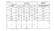
- 4 is a table showing an example of motor specification information used for calculating the rolling fatigue life.
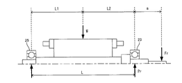
- FIG. 3 is an explanatory diagram for explaining dimensions of a motor included in specification information;
- 4 is a table showing an example of motor specification information used for calculating the life of grease.
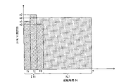
- FIG. 4 is an explanatory diagram showing an example of a rolling fatigue life calculated using an average rotation speed of a motor, and a track record of accumulated operation time and rotation speed;
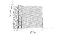
- FIG. 5 is an explanatory diagram showing an example of actual results of rolling fatigue life calculated by the method of the embodiment and operating time converted from the current rotational speed;
- FIG. 5 is an explanatory diagram showing an example of grease life calculated using the average bearing temperature of the motor, and actual results of accumulated operating time and bearing temperature;
- FIG. 4 is an explanatory diagram showing an example of actual results of grease life calculated by the method of the embodiment and operating time converted from the current bearing temperature;
- 4 is a flow chart showing an example of a processing procedure executed by a control unit; It is a block diagram showing the example of hardware constitutions of a motor control device.
- the motor control system 1 has a host controller 3, a motor control device 5, and a motor 7.
- the host controller 3 is a control device that controls the entire motor control system 1 .
- the host controller 3 transmits a control command for controlling the motor 7 to the motor control device 5 .
- a control command is, for example, a position command, a speed command, or the like.
- the host controller 3 is a computer having, for example, an arithmetic unit (CPU), a recording device, an input device, and the like.
- the host controller 3 may be a programmable logic controller (PLC).
- the motor control device 5 includes, for example, a control unit 9 (see FIG. 2 described later) having an arithmetic unit (CPU), a recording device, an input device, etc., and a power conversion unit 11 (see FIG. 2 described later) that supplies power to the motor 7. ), etc.
- the power converter 11 converts power such as frequency, current, and voltage by switching a semiconductor switch, for example.
- the motor control device 5 supplies power to the motor 7 and controls the operation of the motor 7 based on the control command received from the host controller 3 .
- the motor control device 5 may be an inverter device that variably controls the rotation speed of the motor 7, for example.
- the motor control device 5 may be, for example, a servo amplifier used for controlling the motor 7, which is a servo motor.
- the motor control device 5 may be a matrix converter that converts AC power into AC power of different frequencies by switches arranged in a matrix.
- the motor 7 is, for example, an AC motor controlled by the motor control device 5.
- the motor 7 may be any motor provided with bearings, such as an induction motor or a synchronous motor.
- the motor 7 has a stator 13 , a rotor 15 , a frame 17 , brackets 19 and 21 and bearings 23 and 25 .
- Brackets 19 and 21 include load-side bracket 19 and anti-load-side bracket 21 .
- the bearings 23 and 25 are rolling bearings, for example, and include a load side bearing 23 and an anti-load side bearing 25 .
- the "load side” is the direction in which the load is attached to the motor 7, for example, the direction in which the shaft 31 protrudes in FIG. 1 (right side in FIG. 1).
- the "anti-load side” is the direction opposite to the load side (left side in FIG. 1).
- the stator 13 is provided on the inner periphery of the frame 17.
- the stator 13 has a stator core 27 and stator windings 29 .
- the rotor 15 has a shaft 31 and a rotor core 33 provided on the outer circumference of the shaft 31 .
- the rotor core 33 is arranged so as to radially face the stator core 27 .
- the load side bracket 19 is arranged on the load side of the frame 17 (right side in FIG. 1), and the anti-load side bracket 21 is arranged on the anti-load side of the frame 17 (left side in FIG. 1).
- the load-side bearing 23 is fixed to the load-side bracket 19
- the anti-load-side bearing 25 is fixed to the anti-load-side bracket 21 .
- the shaft 31 is rotatably supported around the rotation axis AX by the load-side bearing 23 and the anti-load-side bearing 25 .
- the load-side bearing 23 is configured to be larger in size than the anti-load-side bearing 25, but the size is not limited to this and may be the same size.
- the "axial direction” is the direction along the rotation axis AX of the shaft 31, and the "radial direction” is the radial direction about the rotation axis AX.
- the configuration of the motor control system 1 described above is an example, and is not limited to the content described above.
- the host controller 3 and the motor control device 5 may be configured as a single control device, or each control device may be configured by a plurality of control devices.
- the motor control device 5 has the control section 9 and the power conversion section 11 described above.
- Power conversion unit 11 has converter unit 35 , smoothing capacitor 37 , and inverter unit 39 .
- the converter unit 35 converts AC power supplied from the AC power supply 41 into DC power.
- the smoothing capacitor 37 is connected in parallel with the DC power supply to the positive DC bus 43 and the negative DC bus 45 and smoothes the DC power converted by the converter section 35 .
- the inverter unit 39 converts the DC power into AC power based on the control signal Cs from the control unit 9 and supplies the AC power to the motor 7 to drive the motor 7 .
- the control signal Cs is, for example, a PWM signal or the like.
- the control section 9 mainly controls the inverter section 39 based on a control command (for example, a position command Pc) from the host controller 3 .
- the position detector 47 optically or magnetically detects the rotational position (also referred to as the rotational angle) of the motor 7 to generate position data Pd and transmit it to the control unit 9 .
- the position detector 47 may be, for example, an optical encoder or the like that outputs a pulse signal.
- the control unit 9 acquires the received position data Pd as a feedback motor position Pf (see FIG. 3).
- the control unit 9 converts the received position data Pd into a speed by, for example, difference calculation or the like, and acquires it as a feedback motor speed Vf (see FIG. 3).
- the form of the position data Pd output by the position detector 47 is not particularly limited, and includes various forms such as pulse signal, serial data, and analog sine wave.
- the position detector 47 does not necessarily have to be provided.
- the position detector 47 may not be provided.
- FIG. 3 illustrates a case where the control command from the host controller 3 is, for example, the position command Pc.
- control unit 9 has a position control unit 49, a speed control unit 51, a torque control unit 53, and a differentiator 55.
- the position control unit 49 generates a speed command Vc based on the position deviation Pe between the position command Pc from the host controller 3 and the motor position Pf fed back from the position detector 47 .
- the differentiator 55 converts the position data Pd received from the position detector 47 into speed by, for example, difference calculation, and outputs the motor speed Vf.
- the speed control unit 51 generates a torque command Tc based on the speed deviation Ve between the speed command Vc and the motor speed Vf output from the differentiator 55 .
- the torque control unit 53 converts the torque command Tc from the speed control unit 51 into a current command, generates a voltage command from the current command and a fed-back motor current (not shown), and generates a control signal Cs based on the voltage command. to generate The control signal Cs is output to the inverter section 39 .
- control unit 9 The configuration of the control unit 9 described above is an example, and is not limited to the content described above.
- the command received from the host controller 3 is a speed command
- the position control section 49 becomes unnecessary.
- the speed control unit 51 may generate the torque command Tc based on the speed deviation Ve between the speed command Vc from the host controller 3 and the motor speed Vf.
- the motor control device 5 may perform, for example, V/F control that keeps the ratio between the voltage and the frequency output from the power converter 11 constant. Further, the motor control device 5 divides the current flowing through the motor 7 into a current component that generates torque and a current component that generates magnetic flux in the rotor. Vector control that controls as a quantity may be performed.
- control unit 9 includes an information acquiring unit 57, an operating time integrating unit 59, a specification information recording unit 61, a total life time calculating unit 63, an integrated operating time converting unit 65, a residual It has a life time calculation section 67 and an information output section 69 .
- the information acquisition unit 57 acquires information related to the current operating conditions of the motor 7.
- the "information related to operating conditions” includes, for example, the number of rotations of the motor 7, bearing temperature, shaft end load, model, etc., but may include information other than these.
- the "current operating conditions” are the initial conditions for starting the operation of the motor 7 if the operating conditions are not changed, and the current operating conditions after the change if the operating conditions are changed while the motor 7 is operating. (operating conditions from the present to the time of the next operating condition change).
- the information acquisition section 57 may acquire the number of revolutions based on the speed command Vc output from the position control section 49 described above, for example. For example, when the motor control device 5 performs V/F control or the like, the information acquisition section 57 may acquire the number of revolutions based on the frequency command.
- the information acquisition unit 57 receives input from a user via an input device 913 (see FIG. 13 described later) provided in the motor control device 5, for example, or an external input device (not shown) communicably connected to the motor control device 5, for example. You can get the information you entered.
- the information acquisition section 57 may acquire necessary information by performing a predetermined calculation based on the information input by the user and the specification information recorded in the specification information recording section 61 .
- the specification information includes the temperature rise value of the load side bearing 23
- the actual temperature of the load side bearing 23 may be estimated by adding the temperature rise value to the ambient temperature of the motor 7 input by the user. .
- the information acquisition unit 57 may acquire information from the detection signal of a sensor that detects information related to the current operating conditions of the motor 7 .
- the information acquisition unit 57 may acquire the number of revolutions based on the position data Pd output from the position detector 47, which is an example of a sensor.
- the information acquisition unit 57 may acquire the ambient temperature or bearing temperature of the motor 7 from the thermometer.
- a thermometer that detects the coil temperature of the motor 7, which is an example of a sensor may be installed.
- the specification information includes correlation information between the temperature rise value of the coil and the temperature rise value of the coil and the bearing.
- the actual temperature of bearing 23 may be estimated.
- the operating time accumulator 59 accumulates the operating time (also called operating time) of the motor 7 .
- the operating time accumulating unit 59 accumulates the operating time of the motor 7 and the consumption life associated with the operating condition at that time for each operating time.
- the cumulative consumption life may be the sum of the product of the operating time and the number of revolutions.
- the cumulative consumption life may be the sum of the product of the operating time and the bearing temperature.
- the operating time accumulator 59 When the bearing or grease is replaced, the operating time accumulator 59 resets the cumulative operating time of each along with the replacement.
- the operating time accumulator 59 may calculate the cumulative consumption life as the sum of the product of the operating time and the operating conditions in the same manner as described above, even when the operating conditions are other than the above-described rotational speed and bearing temperature.
- the specification information recording unit 61 (an example of the information recording unit) records various specification information regarding the motor 7 driven by the motor control device 5 and the bearings 23 and 25 .
- the specification information includes motor dimensions, motor test data, rating information of the bearings 23 and 25, and the like.
- the specification information recording unit 61 may record specification information regarding the motors 7 of a plurality of models. In this case, the specification information on all motor models provided by the motor manufacturer may be recorded, or the specification information limited to the model of the motor to be controlled based on the rated output capacity of the motor control device 5 may be recorded. Information may be recorded. When the specification information about a plurality of models of motors is recorded in the specification information recording unit 61, the user may select which model of motor the specification information is to be used.
- the specification information recorded in the specification information recording unit 61 and the operating time information recorded in the operating time accumulating unit 59 of the motor control device 5 before updating are updated. It can be handed over to the specification information recording unit 61 and the operation time accumulating unit 59 of the motor control device 5 later.
- the total life time calculation unit 63 calculates the total life time of the load side bearing 23 or the grease (an example of lubricant) of the load side bearing 23 from the start of operation of the motor 7 based on the current operating conditions of the motor.
- the total life time calculator 63 has a rolling fatigue life calculator 71 and a grease life calculator 73 .
- the rolling fatigue life calculator 71 calculates the rolling fatigue life of the load side bearing 23 .
- the rolling fatigue life is the life until damage such as flaking occurs on the rolling surface of the rolling bearing.
- the grease life calculator 73 calculates the grease life of the load-side bearing 23 .
- the grease life is the life until the grease of the rolling bearing deteriorates and causes seizure.
- the rolling fatigue life calculation unit 71 calculates the rolling fatigue life L(h) based on the specification information of the motor and the following formula 1.
- FIG. 5 shows an example of motor specification information used to calculate the rolling fatigue life L(h).
- the unit of the rolling fatigue life L (h) is time (h), but it may be the total number of revolutions.
- the rolling fatigue life calculator 71 calculates the rolling fatigue life L(h) based on the following formula 2 in the case of a roller bearing.
- a1 is the reliability factor
- a2 is the bearing characteristic factor
- a3 is the usage condition factor.
- All of the coefficients a1, a2, and a3 are values in the range of 0 to 1, and are set according to the user's judgment according to the actual operating conditions of the motor 7.
- FIG. n is the current number of revolutions of the motor 7, which is obtained based on, for example, the speed command Vc as described above.
- C is the rating information of the bearing included in the specification information, which is the basic dynamic load rating (N).
- Pr is the bearing load that is the radial load of the load side bearing 23 .
- the rolling fatigue life calculation unit 71 calculates the bearing load Pr based on the specification information of the motor and the following formula 3.
- Fr is the shaft end load, which is the radial load on the load side of the shaft 31 of the motor 7, and is input by the user via an input device, for example.
- W is the resultant force obtained by the sum of the mass of the rotor 15 of the motor 7 and the unbalanced magnetic attraction force between the stator 13 and the rotor 15, and L1 is the action of the resultant force W from the center position of the anti-load side bearing 25.
- a is the axial distance from the center position of the load side bearing 23 to the point of application of the shaft end load Fr
- L2 is the axial distance from the point of action of the resultant force W to the center position of the load side bearing 23
- L is the total distance of L1 and L2.
- the rolling fatigue life calculator 71 calculates the rolling fatigue life L(h) based on the current actual rotation speed n of the motor 7 .
- FIG. 7 shows an example of motor specification information used to calculate the grease life Log(L). Although information related to the dimensions of the motor described above is also used, it is omitted in FIG. 7 because it is the same as in FIG.
- n is the current rotation speed of the motor 7, which is obtained based on, for example, the speed command Vc as described above.
- N and C are rating information of the load side bearing 23 included in the specification information
- N is the allowable rotation speed (r/min)
- C is the basic dynamic load rating (N).
- T is the actual temperature of the bearing, and as described above, for example, based on the ambient temperature input by the user via the input device and the bearing temperature rise value (K) or the coil temperature rise value (K) included in the specification information may be estimated using
- the bearing load Pr is calculated based on Equation 3 described above. Calculation formula 4 can be applied to various types of grease by changing the coefficient depending on the grease to be used.
- the grease life calculation unit 73 calculates the grease life based on the current actual rotation speed n of the motor 7 and the current estimated bearing temperature of the load side bearing 23 .
- the total life time calculation unit 63 may use the shorter of the calculated rolling fatigue life L (h) and grease life L (h) as the total life time of the load side bearing 23 .
- the accumulated operating time conversion unit 65 converts the accumulated operating time ⁇ T1 (an example of the first accumulated operating time) accumulated by the operating time accumulating unit 59 into the accumulated operating time ⁇ T2 (second accumulated operating time) based on the current operating conditions. Example of time).
- the cumulative operating time conversion section 65 may convert the cumulative operating time using, for example, the aforementioned cumulative consumption life. For example, as shown in FIG.
- the remaining life time calculation unit 67 calculates the remaining life time of the load side bearing 23 or grease by subtracting the integrated operating time ⁇ T2 from the total life time.
- a case of calculating the remaining life time of the bearing for example, when the rolling fatigue life L(h) is shorter than the grease life L(h) will be described.
- FIG. 9 shows the rolling fatigue life L(h) calculated based on the rotational speed n3, which is the current operating condition, based on Equations 1 to 3 described above.
- FIG. 8 shows, as a comparative example with respect to the embodiment, the rolling fatigue life Lo calculated using the average rotational speed n0 of the motor 7 based on the above-described calculation formulas 1 to 3.
- the rolling fatigue life Lo is the total life time when the motor 7 continues to operate from the start of operation at the average rotation speed n0. Therefore, when the number of rotations of the motor 7 fluctuates as shown in FIG. 8, the remaining life time RL1 may deviate from the actual operating conditions of the motor 7.
- FIG. 8 shows, as a comparative example with respect to the embodiment, the rolling fatigue life Lo calculated using the average rotational speed n0 of the motor 7 based on the above-described calculation formulas 1 to 3.
- the current rotation speed n3, which is the actual operating condition of the motor 7, is used to calculate the rolling fatigue life L(h).
- the rolling fatigue life L(h) is the total life time when the motor 7 continues to operate from the start of operation at the number of revolutions n3, which is the current operating condition.
- the accumulated operating time is converted using the current rotation speed n3 and subtracted from the rolling fatigue life L(h) to calculate the remaining life time RL2. Therefore, it is possible to estimate the remaining life time from the current time that matches the current actual operating conditions, regardless of the fluctuation in the number of revolutions of the motor 7 before the current time.
- the remaining life time RL2 is longer than the remaining life time RL1 by the amount that the rotation speed n3, which is the current actual operating condition, is lower than the average rotation speed n0 shown in FIG.
- FIG. 11 shows the grease life L(h) calculated based on the bearing temperature t3, which is the current operating condition, based on the calculation formulas 3 and 4 described above.
- FIG. 10 shows, as a comparative example with respect to the embodiment, the grease life Lo calculated using the average bearing temperature t0 of the motor 7 based on the calculation formulas 3 and 4 described above.
- the grease life Lo is the total life time when the motor 7 continues to operate from the start of operation at the average bearing temperature t0. Therefore, when the bearing temperature of the load-side bearing 23 fluctuates, for example, as shown in FIG.
- the grease life L(h) is calculated using the current bearing temperature t3 of the load side bearing 23, which is the actual operating condition of the motor 7.
- the grease life L(h) is the total life time when the motor 7 continues to operate from the start of operation at the bearing temperature t3, which is the current operating condition.
- the accumulated operating time is converted using the current bearing temperature t3 and subtracted from the grease life L(h) to calculate the remaining life time RL2. Therefore, it is possible to estimate the remaining life time from the current time that matches the current actual operating conditions, regardless of the fluctuations in the bearing temperature of the load-side bearing 23 before the current time.
- the remaining life time RL2 is shorter than the remaining life time RL1 by the amount that the bearing temperature t3, which is the current actual operating condition, is higher than the average bearing temperature t0 shown in FIG.
- the remaining life time RL2 is the remaining life time when the operation is continued under the current operating conditions of the rotation speed n3 and the bearing temperature t3. For this reason, if the operating conditions are changed in the future, in the same way as above, the changed operating conditions will be used to accumulate the operating hours, calculate the total life time, convert the accumulated operating hours, and calculate the remaining life time. Calculation and the like may be performed again. In this way, by recalculating the remaining life time each time the operating conditions are changed, it is possible to further improve the accuracy of estimating the remaining life time.
- the information output unit 69 outputs the calculated remaining life time RL2.
- the information output unit 69 may display, for example, via an output device 915 (see FIG. 13 described later) such as a display device of the motor control device 5, or may be connected to the motor control device 5 so as to be communicable. It may be transmitted to an external output device (not shown).
- the processing in the information acquiring unit 57, the operating time accumulating unit 59, the specification information recording unit 61, the total life time calculating unit 63, the accumulated operating time converting unit 65, the remaining life time calculating unit 67, the information output unit 69, etc. is not limited to these examples of sharing of processing, for example, processing may be performed by a smaller number of processing units (for example, one processing unit), or processing may be performed by more subdivided processing units.
- the above processing and the like of the control unit 9 may be implemented by a program executed by the CPU 901 (see FIG. 13) described later, or part or all of it may be implemented by an actual device such as an ASIC, FPGA, or other electric circuit. may be
- step S10 the control unit 9 integrates the operation time of the motor 7 by the operation time integration unit 59.
- the control unit 9 integrates the operation time of the motor 7 and calculates an integrated consumption life ⁇ CL, which is the sum of products of each operation time and the operating conditions at that time.
- step S20 the control unit 9 uses the information acquisition unit 57 to acquire information such as the motor model, shaft end load Fr, and ambient temperature.
- information acquisition unit 57 uses the information acquisition unit 57 to acquire information such as the motor model, shaft end load Fr, and ambient temperature.
- the information may be acquired based on an input by the user or a sensor signal.
- step S ⁇ b>30 the control unit 9 causes the total life time calculation unit 63 to calculate the load from the start of operation of the motor 7 according to the current operating conditions of the motor 7 and the specification information recorded in the specification information recording unit 61 . Calculate the total life time of the side bearing 23 or grease.
- the current operating conditions of the motor 7 are, for example, the number of revolutions and the bearing temperature.
- the rotational speed may be obtained, for example, based on the speed command Vc, and the bearing temperature may be obtained, for example, based on the ambient temperature and the bearing temperature rise value included in the specification information.
- the controller 9 uses the rolling fatigue life calculator 71 to calculate the rolling fatigue life L(h) and the grease life calculator 73 to calculate the grease life L(h).
- the control unit 9 may use the shorter one of these times as the total life time of the load-side bearing 23 .
- step S40 the control unit 9 causes the integrated operating time conversion unit 65 to convert the integrated operating time ⁇ T1 integrated in step S10 into the integrated operating time ⁇ T2 based on the integrated life consumption ⁇ CL and the current operating conditions of the motor 7. Convert to
- step S50 the control unit 9 causes the remaining life time calculation unit 67 to calculate the accumulated operating time converted in upper step S40 from the rolling fatigue life L (h) or grease life L (h) calculated in step S30. By subtracting ⁇ T2, the remaining life time RL2 of the load side bearing 23 or grease is calculated.
- step S60 the control unit 9 causes the information output unit 69 to output the remaining life time RL2 calculated in step S50.
- the remaining life time RL2 calculated in step S50.
- various modes of outputting the remaining life time RL2 in step S60 are conceivable. good. This completes the flowchart.
- processing procedure is an example, and at least part of the above procedure may be deleted or changed, and procedures other than the above may be added. Moreover, the order of at least part of the above procedures may be changed, and a plurality of procedures may be combined into a single procedure.
- the motor control system 1 of the embodiment has the motor 7 having the bearings 23 and 25 and the motor control device 5 that controls the motor 7 .
- an operating time accumulating unit 59 for accumulating the operating time; and a total life time calculating unit 63 for calculating the total life time of the load side bearing 23 or grease from the start of operation of the motor 7 based on the current operating conditions of the motor 7.
- an integrated operating time conversion unit 65 that converts the integrated operating time ⁇ T1 integrated by the operating time accumulating unit 59 into an integrated operating time ⁇ T2 based on the current operating conditions; and a remaining life time calculator 67 that calculates the remaining life time RL2 of the side bearing 23 or the grease.
- the total life time of the load side bearing 23 or the grease of the load side bearing 23 is calculated based on the current operating conditions of the motor 7 .
- the total service life of the load-side bearing 23 or grease from the start of motor operation matches the actual operating conditions based on the current actual operating conditions.
- the operating time of the motor 7 is accumulated, and the accumulated operating time ⁇ T1 is added to the accumulated operating time ⁇ T2 corresponding to the current operating conditions.
- the remaining life time is calculated by subtracting the integrated operating time ⁇ T2 from the calculated total life time of the load-side bearing 23 or grease.
- the remaining life time of the load-side bearing 23 or the grease that matches the actual operating conditions of the motor 7 from the present time.
- the accuracy of life prediction is improved, and an efficient maintenance plan for the motor 7 can be made.
- the motor control device 5 has a specification information recording unit 61 that records specification information about the motor 7, and the total life time calculation unit 63 stores the specification information recorded in the specification information recording unit 61. You may calculate the total life time of the load side bearing 23 or grease based on.
- the non-disclosed specification information as described above is recorded in the specification information recording unit 61 of the motor control device 5 . Therefore, the total life time calculation unit 63 of the motor control device 5 can calculate the total life time of the load side bearing 23 or the grease based on the recorded specification information. Thereby, the user can grasp the remaining life time of the load side bearing 23 or the grease without inquiring the motor manufacturer.
- the specification information may include the unbalanced magnetic attraction force between the stator 13 and rotor 15 of the motor 7.
- the unbalanced magnetic attraction force of a motor is not disclosed to users, and it is information that can only be obtained by contacting the motor manufacturer.
- the motor control device 5 since the specification information recorded in the specification information recording unit 61 of the motor control device 5 includes the unbalanced magnetic attractive force, the motor control device 5 adjusts the load side bearing based on the specification information. 23 total life time can be calculated. This allows the user to grasp the more accurate remaining life time RL2 of the load-side bearing 23 or grease without inquiring of the motor manufacturer.
- the motor control device 5 may have an information acquisition section 57 that acquires information regarding the current operating conditions of the motor 7 .
- the information acquisition unit 57 of the motor control device 5 acquires information regarding the current operating conditions of the motor 7 .
- the mode of acquisition is not particularly limited. For example, information input by a user may be acquired, information may be acquired from a detection signal of a sensor, or a command of the motor control device 5 may be acquired.
- This makes it possible to calculate the total life time of the load-side bearing 23 or grease that matches the actual operating conditions of the motor 7 from the start of the motor operation based on the acquired current operating conditions.
- the accumulated operating time ⁇ T1 can be added to the accumulated operating time ⁇ T2 under the acquired current operating conditions. Therefore, it is possible to accurately estimate the remaining life time RL2 from the present time of the load-side bearing 23 or the grease that matches the actual operating conditions of the motor 7 .
- the information acquisition unit 57 acquires at least one of the rotation speed, the temperature of the load-side bearing 23, and the load-side shaft end load Fr of the motor 7 as information related to the current operating conditions of the motor 7. good too.
- the information acquisition unit 57 acquires the current rotational speed of the motor 7, the temperature of the load-side bearing 23, and the load-side shaft end load Fr of the motor 7 as information related to the current operating conditions. It is possible to calculate the total life time of the load-side bearing 23 or grease with higher accuracy that matches the actual operating conditions of the vehicle.
- the motor control device 5 has a control unit 9 that generates a command for controlling the motor 7, and the information acquisition unit 57 obtains You may acquire the rotation speed based on the produced
- control unit 9 has a position control unit 49 that generates a speed command Vc for controlling the rotational speed of the motor 7 based on the position command Pc, and the information acquisition unit 57 obtains the current speed of the motor 7. As the information related to the operating conditions, the number of rotations based on the speed command Vc output from the position control section 49 may be acquired.
- the control unit 9 generates a speed command Vc for controlling the rotation speed of the motor 7, and controls the rotation speed (number of rotations) of the motor 7 so as to follow the command speed.
- the information acquisition unit 57 acquires the number of revolutions as the current operating condition of the motor 7 based on the speed command Vc generated by the position control unit 49 .
- wiring from a sensor (such as the position detector 47) that detects the number of revolutions is not necessary, and the user's input operation is saved. be able to.
- the specification information includes the temperature rise value of the load side bearing 23, the information acquisition unit 57 acquires the ambient temperature of the motor 7, and based on the ambient temperature and the temperature rise value, the load side The temperature of bearing 23 may be estimated.
- the user only needs to input the ambient temperature of the motor 7, so the user's trouble can be reduced and the convenience can be improved. Moreover, since it is not necessary to separately install a thermometer or the like for measuring the temperature of the bearing, the configuration can be simplified and the cost can be reduced.
- the motor control device 5 has a specification information recording unit 61 that records specification information about the motors 7 of a plurality of models. After acquiring the model, the total life time calculation unit 63 may calculate the total life time of the load side bearing 23 or the grease based on the specification information corresponding to the model of the motor 7 acquired by the information acquisition unit 57. .
- the total life time calculator 63 can refer to the specification information corresponding to the acquired model information of the motor 7 to calculate the total life time of the load side bearing 23 or the grease. Therefore, instead of the dedicated motor control system 1 in which the motor control device 5 can estimate the remaining life of the motor 7 of a specific model, a system capable of estimating the remaining life of various types of motors 7 is realized. can. Therefore, the versatility of the motor control system 1 can be improved.
- a motor control system 1 of the embodiment includes a motor 7 having bearings 23 and 25 and a motor control device 5 that controls the motor 7.
- the motor control device 5 records specification information about the motor 7. Based on the specification information recording unit 61 and the current operating conditions and specification information of the motor 7, the total life time of the load side bearing 23 or the grease of the load side bearing 23 from the start of operation of the motor 7 is calculated.
- a configuration including a total life time calculation unit 63 may also be used.
- the total life time calculation unit 63 of the motor control device 5 is based on the recorded specification information. can be used to calculate the total life time of the load side bearing 23 or grease. Thereby, the user can grasp the remaining life time of the load side bearing 23 or the grease without inquiring the motor manufacturer.
- the rolling fatigue life calculation unit 71 and the grease life calculation unit 73 calculate the rolling fatigue life based on the specification information of the motor 7 and the non-load side bearing 25, and the above-described calculation formulas 1, 2, and 4.
- L(h) and grease life L(h) can be calculated.
- the bearing load Pr which is the radial load of the anti-load side bearing 25, can be calculated, for example, based on Equation 5 below.
- the problems to be solved by the invention and the effects of the invention are not limited to the contents described above. That is, the present invention can solve problems not described above, achieve effects not described above, solve only a part of the problems described, or achieve one of the effects described. Sometimes only the part is played.
- the motor control device 5 includes, for example, a CPU 901, a ROM 903, a RAM 905, a dedicated integrated circuit 907 constructed for a specific application such as an ASIC or FPGA, an input device 913, and an output device. 915 , a recording device 917 , a drive 919 , a connection port 921 and a communication device 923 . These components are connected via a bus 909 and an input/output interface 911 so as to be able to transmit signals to each other.
- the program can be recorded in, for example, the ROM 903, the RAM 905, the recording device 917 including a hard disk, and the like.
- the program is temporarily or non-temporarily (permanently) recorded on a removable recording medium 925 such as a magnetic disk such as a flexible disk, an optical disk such as various CDs, MO disks, and DVDs, or a semiconductor memory. You can also keep Such a recording medium 925 can also be provided as so-called package software.
- the programs recorded on these recording media 925 may be read by the drive 919 and recorded on the recording device 917 via the input/output interface 911, bus 909, or the like.
- the program can also be recorded, for example, on a download site, another computer, another recording device, etc. (not shown).
- the program is transferred via a network NW such as LAN or Internet, and the communication device 923 receives this program.
- NW such as LAN or Internet
- the program received by the communication device 923 may be recorded in the recording device 917 via the input/output interface 911, the bus 909, or the like.
- the program can be recorded in an appropriate external connection device 927, for example.
- the program may be transferred via an appropriate connection port 921 and recorded in the recording device 917 via the input/output interface 911, bus 909, or the like.
- the CPU 901 executes various processes in accordance with the programs recorded in the recording device 917 to obtain the information acquisition unit 57, the operation time integration unit 59, the specification information recording unit 61, and the total life time calculation unit 63. , the integrated operation time conversion unit 65, the remaining life time calculation unit 67, the information output unit 69, and the like.
- the CPU 901 may, for example, directly read out the program from the recording device 917 and execute it, or load the program once into the RAM 905 and execute it.
- the CPU 901 receives a program via the communication device 923 , the drive 919 , or the connection port 921 , for example, the received program may be directly executed without being recorded in the recording device 917 .
- the CPU 901 may perform various processing based on signals and information input from an input device 913 such as a mouse, keyboard, microphone, touch panel (not shown), etc., as necessary.
- an input device 913 such as a mouse, keyboard, microphone, touch panel (not shown), etc., as necessary.
- the CPU 901 may output the result of executing the above processing from an output device 915 such as a display device or an audio output device. It may be transmitted via the port 921 or may be recorded in the recording device 917 or the recording medium 925 .
- an output device 915 such as a display device or an audio output device. It may be transmitted via the port 921 or may be recorded in the recording device 917 or the recording medium 925 .
Landscapes
- Engineering & Computer Science (AREA)
- Power Engineering (AREA)
- Control Of Electric Motors In General (AREA)
Abstract
【課題】実運転状況に合致した現時点からの残寿命を推定する。 【解決手段】モータ制御システム1は、軸受23,25を備えたモータ7と、モータ7を制御するモータ制御装置5と、を有し、モータ制御装置5は、モータ7の運転時間を積算する運転時間積算部59と、モータ7の現在の運転条件に基づいて、モータ7の稼動開始からの負荷側軸受23又はグリースの総寿命時間を算出する総寿命時間算出部63と、運転時間積算部59により積算された積算運転時間ΣT1を、現在の運転条件に基づいて積算運転時間ΣT2に換算する積算運転時間換算部65と、総寿命時間から積算運転時間ΣT2を減じて負荷側軸受23又はグリースの残寿命時間RL2を算出する残寿命時間算出部67と、を有する。
Description
開示の実施形態は、モータ制御システム、モータ制御装置、及び残寿命推定方法に関する。
特許文献1には、転がり軸受の残存寿命予測方法が記載されている。この転がり軸受の残存寿命予測方法では、残存寿命Ldhを、実質的に次式Ldh=0.032×{(1×10⁶)/60N}×(C/P)3.37に基づいて予測する。ここで、Cは軸受の動定格荷重、Pは軸受に作用する荷重、Nは軸受の使用回転数である。
上記従来技術の残存寿命予測方法では、実際の運転条件に基づく実運転状況に合致した現時点からの残寿命を推定することができなかった。
本発明はこのような問題点に鑑みてなされたものであり、実運転状況に合致した現時点からの残寿命を推定することができるモータ制御システム、モータ制御装置、及び残寿命推定方法を提供することを目的とする。
上記課題を解決するため、本発明の一の観点によれば、軸受を備えたモータと、前記モータを制御するモータ制御装置と、を有し、前記モータ制御装置は、前記モータの運転時間を積算する運転時間積算部と、前記モータの現在の運転条件に基づいて、前記モータの稼動開始からの前記軸受または前記軸受の潤滑材の総寿命時間を算出する総寿命時間算出部と、前記運転時間積算部により積算された第1の積算運転時間を、前記現在の運転条件に基づいて第2の積算運転時間に換算する積算運転時間換算部と、前記総寿命時間から前記第2の積算運転時間を減じて前記軸受または前記潤滑材の残寿命時間を算出する残寿命時間算出部と、を有する、モータ制御システムが適用される。
また、本発明の別の観点によれば、軸受を備えたモータと、前記モータを制御するモータ制御装置と、を有し、前記モータ制御装置は、前記モータに関する諸元情報を記録する情報記録部と、前記モータの現在の運転条件と前記諸元情報とに基づいて、前記モータの稼動開始からの前記軸受または前記軸受の潤滑材の総寿命時間を算出する総寿命時間算出部と、を有する、モータ制御システムが適用される。
また、本発明の別の観点によれば、軸受を備えたモータと、前記モータを制御するモータ制御装置と、を有し、前記モータ制御装置は、前記モータの運転時間を積算し、前記モータの現在の運転条件に基づいて、前記モータの稼動開始からの前記軸受または前記軸受の潤滑材の総寿命時間を算出し、前記運転時間積算部により積算された第1の積算運転時間を、前記現在の運転条件に基づいて第2の積算運転時間に換算し、前記総寿命時間から前記第2の積算運転時間を減じて前記軸受または前記潤滑材の残寿命時間を算出する、モータ制御システムが適用される。
また、本発明の別の観点によれば、軸受を備えたモータを制御するモータ制御装置であって、前記モータの運転時間を積算する運転時間積算部と、前記モータの現在の運転条件に基づいて、前記モータの稼動開始からの前記軸受または前記軸受の潤滑材の総寿命時間を算出する総寿命時間算出部と、前記運転時間積算部により積算された第1の積算運転時間を、前記現在の運転条件に基づいて第2の積算運転時間に換算する積算運転時間換算部と、前記総寿命時間から前記第2の積算運転時間を減じて前記軸受または前記潤滑材の残寿命時間を算出する残寿命時間算出部と、を有する、モータ制御装置が適用される。
また、本発明の別の観点によれば、軸受を備えたモータを制御するモータ制御装置であって、前記モータに関する諸元情報を記録する情報記録部と、前記モータの現在の運転条件と前記諸元情報とに基づいて、前記モータの稼動開始からの前記軸受または前記軸受の潤滑材の総寿命時間を算出する総寿命時間算出部と、を有する、モータ制御装置が適用される。
また、本発明の別の観点によれば、モータが備える軸受または前記軸受の潤滑材の残寿命を推定する残寿命推定方法であって、前記モータの運転時間を積算することと、前記モータの現在の運転条件に基づいて、前記モータの稼動開始からの前記軸受または前記潤滑材の総寿命時間を算出することと、積算された第1の積算運転時間を、前記現在の運転条件に基づいて第2の積算運転時間に換算することと、前記総寿命時間から前記第2の積算運転時間を減じて前記軸受または前記潤滑材の残寿命時間を算出することと、を有する、残寿命推定方法が適用される。
本発明によれば、実運転状況に合致した現時点からの残寿命を推定することができる。
以下、実施の形態について図面を参照しつつ説明する。
<1.モータ制御システムの全体構成>
図1を参照しつつ、実施形態に係るモータ制御システムの全体構成の一例について説明する。
図1を参照しつつ、実施形態に係るモータ制御システムの全体構成の一例について説明する。
図1に示すように、モータ制御システム1は、上位コントローラ3と、モータ制御装置5と、モータ7とを有する。
上位コントローラ3は、モータ制御システム1全体の制御を行う制御装置である。上位コントローラ3は、モータ7を制御するための制御指令をモータ制御装置5に送信する。制御指令は、例えば位置指令や速度指令等である。上位コントローラ3は、例えば演算装置(CPU)、記録装置、入力装置等を有するコンピュータである。上位コントローラ3は、プログラマブルロジックコントローラ(PLC)でもよい。
モータ制御装置5は、例えば演算装置(CPU)、記録装置、入力装置等を有する制御部9(後述の図2参照)と、モータ7に電力を供給する電力変換部11(後述の図2参照)等を有する。電力変換部11は、例えば半導体スイッチのスイッチングにより、周波数、電流、電圧等の電力の変換を行う。モータ制御装置5は、上位コントローラ3から受信した制御指令に基づいてモータ7へ電力を供給し、モータ7の動作を制御する。モータ制御装置5は、例えばモータ7の回転数を可変に制御するインバータ装置でもよい。モータ制御装置5は、例えばサーボモータであるモータ7の制御に用いられるサーボアンプでもよい。モータ制御装置5は、マトリックス状に配置されたスイッチにより交流電力を周波数の異なる交流電力に変換するマトリックスコンバータでもよい。
モータ7は、モータ制御装置5により制御される例えば交流モータである。モータ7は、軸受を備えたモータであればよく、例えば誘導モータでもよいし同期モータでもよい。モータ7は、固定子13と、回転子15と、フレーム17と、ブラケット19,21と、軸受23,25とを有する。ブラケット19,21は、負荷側ブラケット19と反負荷側ブラケット21とを含む。軸受23,25は例えば転がり軸受であり、負荷側軸受23と反負荷側軸受25とを含む。「負荷側」とはモータ7に対して負荷が取り付けられる方向、図1では例えばシャフト31が突出する方向(図1中右側)である。「反負荷側」とは負荷側の反対方向(図1中左側)である。
固定子13は、フレーム17の内周に設けられる。固定子13は、固定子鉄心27と、固定子巻線29とを有する。回転子15は、シャフト31と、シャフト31の外周に設けられた回転子鉄心33とを有する。回転子鉄心33は、固定子鉄心27と径方向に対向するように配置される。
負荷側ブラケット19は、フレーム17の負荷側(図1中右側)に配置され、反負荷側ブラケット21は、フレーム17の反負荷側(図1中左側)に配置されている。負荷側軸受23は、負荷側ブラケット19に固定され、反負荷側軸受25は、反負荷側ブラケット21に固定されている。シャフト31は、負荷側軸受23と反負荷側軸受25により、回転軸心AX周りに回転自在に支持されている。図1に示す例では、例えば負荷側軸受23が反負荷側軸受25よりもサイズが大きく構成されているが、これに限らず同等のサイズとしてもよい。
実施形態において「軸方向」とはシャフト31の回転軸心AXに沿った方向、「径方向」とは回転軸心AXを中心とする半径方向である。
上述したモータ制御システム1の構成は一例であり、上述の内容に限定されるものではない。例えば、上位コントローラ3とモータ制御装置5とは、単一の制御装置として構成されてもよいし、各制御装置が複数の制御装置で構成されてもよい。
<2.モータ制御装置の機能構成>
図2を参照しつつ、モータ制御装置5の機能構成の一例について説明する。
図2を参照しつつ、モータ制御装置5の機能構成の一例について説明する。
図2に示すように、モータ制御装置5は、前述の制御部9と電力変換部11とを有する。電力変換部11は、コンバータ部35と、平滑コンデンサ37と、インバータ部39とを有する。
コンバータ部35は、交流電源41から供給される交流電力を直流電力に変換する。平滑コンデンサ37は、正側直流母線43及び負側直流母線45に対して直流電源と並列に接続され、コンバータ部35により変換された直流電力を平滑化する。インバータ部39は、制御部9からの制御信号Csに基づき直流電力を交流電力に変換し、モータ7に供給してモータ7を駆動する。制御信号Csは例えばPWM信号等である。
制御部9は、上位コントローラ3からの制御指令(例えば位置指令Pc)に基づき、主としてインバータ部39の制御を行う。
位置検出器47は、モータ7の回転位置(回転角度ともいう)を光学的または磁気的に検出して位置データPdを生成し、制御部9に送信する。位置検出器47は、例えばパルス信号を出力する光学式のエンコーダ等でもよい。制御部9は、受信した位置データPdをフィードバックされたモータ位置Pf(図3参照)として取得する。制御部9は、受信した位置データPdを例えば差分演算等で速度に変換し、フィードバックされたモータ速度Vf(図3参照)として取得する。位置検出器47が出力する位置データPdの形態は、特に限定されるものではなく、例えばパルス信号、シリアルデータ、アナログ正弦波等、種々の形態を含む。
なお、位置検出器47は必ずしも設ける必要はない。例えばV/F制御やベクトル制御を行う場合等、位置データPd等をフィードバックせずにモータ7を制御する場合には、位置検出器47を設けない構成としてもよい。
<3.制御部のモータ制御に関わる機能構成>
図3を参照しつつ、制御部9のモータ制御に関わる機能構成の一例について説明する。図3では、上位コントローラ3からの制御指令が例えば位置指令Pcである場合について説明する。
図3を参照しつつ、制御部9のモータ制御に関わる機能構成の一例について説明する。図3では、上位コントローラ3からの制御指令が例えば位置指令Pcである場合について説明する。
図3に示すように、制御部9は、位置制御部49と、速度制御部51と、トルク制御部53と、差分器55とを有する。
位置制御部49は、上位コントローラ3からの位置指令Pcと位置検出器47からフィードバックされたモータ位置Pfとの位置偏差Peに基づき、速度指令Vcを生成する。差分器55は、位置検出器47から受信した位置データPdを例えば差分演算等により速度に変換し、モータ速度Vfを出力する。速度制御部51は、速度指令Vcと差分器55から出力されたモータ速度Vfとの速度偏差Veに基づき、トルク指令Tcを生成する。トルク制御部53は、速度制御部51からのトルク指令Tcを電流指令に変換し、当該電流指令とフィードバックされたモータ電流(図示省略)から電圧指令を生成し、当該電圧指令に基づき制御信号Csを生成する。制御信号Csは、インバータ部39に出力される。
上述した制御部9の構成は一例であり、上述の内容に限定されるものではない。例えば、上位コントローラ3から受信する指令が速度指令である場合には、位置制御部49は不要となる。この場合、速度制御部51は、上位コントローラ3からの速度指令Vcとモータ速度Vfとの速度偏差Veに基づきトルク指令Tcを生成すればよい。
なお、モータ制御装置5は、上述の位置制御や速度制御に代えて、例えば電力変換部11から出力される電圧と周波数の比を一定にするV/F制御を行ってもよい。またモータ制御装置5は、モータ7に流れる電流を、トルクを発生する電流成分と回転子に磁束を発生させる電流成分とに分けて考え、モータ7の回転磁界の磁束の方向と大きさをベクトル量として制御するベクトル制御を行ってもよい。
<4.制御部の残寿命推定に関わる機能構成>
図4を参照しつつ、制御部9の残寿命推定に関わる機能構成の一例について説明する。負荷側軸受23は反負荷側軸受25よりも負荷が大きいため、寿命が短くなるのが一般的である。このため、実施形態では負荷側軸受23の残寿命を推定する場合について説明する。
図4を参照しつつ、制御部9の残寿命推定に関わる機能構成の一例について説明する。負荷側軸受23は反負荷側軸受25よりも負荷が大きいため、寿命が短くなるのが一般的である。このため、実施形態では負荷側軸受23の残寿命を推定する場合について説明する。
図4に示すように、制御部9は、情報取得部57と、運転時間積算部59と、諸元情報記録部61と、総寿命時間算出部63と、積算運転時間換算部65と、残寿命時間算出部67と、情報出力部69とを有する。
情報取得部57は、モータ7の現在の運転条件に関わる情報を取得する。「運転条件に関わる情報」には、例えばモータ7の回転数、軸受温度、軸端荷重、機種等が含まれるが、これら以外の情報が含まれてもよい。「現在の運転条件」とは、運転条件の変更がない場合はモータ7の稼動開始の初期条件であり、モータ7の稼動中に運転条件を変更した場合には、変更後の現時点の運転条件(現在から次回の運転条件変更時までの間の運転条件)である。
情報取得部57による情報の取得態様は様々な態様が考えられる。情報取得部57は、例えば前述の位置制御部49から出力される速度指令Vcに基づいて回転数を取得してもよい。情報取得部57は、例えばモータ制御装置5がV/F制御等を行う場合には周波数指令に基づいて回転数を取得してもよい。情報取得部57は、例えばモータ制御装置5が備える入力装置913(後述の図13参照)、又は、例えばモータ制御装置5と通信可能に接続された外部入力装置(図示省略)を介してユーザが入力した情報を取得してもよい。この場合、情報取得部57は、ユーザが入力した情報と、諸元情報記録部61に記録された諸元情報とに基づいて、所定の演算を行って必要な情報を取得してもよい。例えば諸元情報が負荷側軸受23の温度上昇値を含んでいる場合、ユーザにより入力されたモータ7の周囲温度に温度上昇値を加算して負荷側軸受23の実温度を推定してもよい。
情報取得部57は、モータ7の現在の運転条件に関わる情報を検出するセンサの検出信号から情報を取得してもよい。例えば情報取得部57は、センサの一例である位置検出器47から出力される位置データPdに基づいて回転数を取得してもよい。例えばセンサの一例であるモータ7の周囲温度又は軸受温度を検出する温度計を設置した場合には、情報取得部57は温度計からモータ7の周囲温度又は軸受温度等を取得してもよい。例えばセンサの一例であるモータ7のコイル温度を検出する温度計を設置してもよい。この場合、例えば諸元情報にコイルの温度上昇値とコイル及び軸受の温度上昇値の相関情報を含めておき、情報取得部57は温度計から取得したコイル温度と諸元情報に基づいて負荷側軸受23の実温度を推定してもよい。
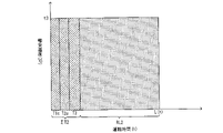
運転時間積算部59は、モータ7の運転時間(稼働時間ともいう)を積算する。運転時間積算部59は、モータ7の運転時間を積算すると共に、各運転時間についてその時の運転条件と関連付けた消費寿命を積算する。例えば運転条件を回転数とする場合、積算消費寿命は運転時間と回転数の積の合計としてもよい。具体的には、例えば後述の図8に示すように、モータ7を回転数n1で運転時間T1、回転数n2で運転時間T2、回転数n3で運転時間T3だけ運転した場合、積算運転時間ΣT1はΣT1=T1+T2+T3となる。積算消費寿命ΣCLはΣCL=T1×n1+T2×n2+T3×n3(図8中斜線ハッチング部分の面積)となる。
例えば運転条件を軸受温度とする場合、積算消費寿命は運転時間と軸受温度の積の合計としてもよい。具体的には、例えば後述の図10に示すように、軸受温度t1で運転時間T1、軸受温度t2で運転時間T2、軸受温度t3で運転時間T3だけ運転した場合、積算運転時間ΣT1はΣT1=T1+T2+T3となる。積算消費寿命ΣCLはΣCL=T1×t1+T2×t2+T3×t3(図10中斜線ハッチング部分の面積)となる。
運転時間積算部59は、軸受またはグリースが交換された場合には、交換に伴ってそれぞれの運転時間の積算をリセットする。運転時間積算部59は、運転条件が上述した回転数や軸受温度以外の場合でも、上記と同様に積算消費寿命を運転時間と運転条件の積の合計として算出してもよい。
諸元情報記録部61(情報記録部の一例)は、モータ制御装置5により駆動されるモータ7及び軸受23,25に関する各種の諸元情報を記録する。諸元情報には、モータの寸法、モータの試験データ、軸受23,25の定格情報等が含まれている。諸元情報記録部61は、複数の機種のモータ7に関する諸元情報を記録してもよい。この場合、モータメーカが提供している全機種のモータに関する諸元情報を記録してもよいし、モータ制御装置5の定格出力の容量に基づいて制御対象となるモータの機種に限定した諸元情報を記録してもよい。諸元情報記録部61に複数の機種のモータに関する諸元情報を記録する場合には、どの機種のモータの諸元情報を使用するかをユーザが選択してもよい。
なお、モータ制御装置5が更新された場合、更新前のモータ制御装置5の諸元情報記録部61に記録された諸元情報および運転時間積算部59に記録された運転時間情報は、それぞれ更新後のモータ制御装置5の諸元情報記録部61および運転時間積算部59に引き継ぐことができる。
総寿命時間算出部63は、モータの現在の運転条件に基づいて、モータ7の稼動開始からの負荷側軸受23又は負荷側軸受23のグリース(潤滑材の一例)の総寿命時間を算出する。総寿命時間算出部63は、転がり疲れ寿命算出部71とグリース寿命算出部73とを有する。転がり疲れ寿命算出部71は、負荷側軸受23の転がり疲れ寿命を算出する。転がり疲れ寿命とは、転がり軸受の転走面に例えばフレーキング等の損傷が起こるまでの寿命である。グリース寿命算出部73は、負荷側軸受23のグリース寿命を算出する。グリース寿命とは、転がり軸受のグリースが劣化して焼き付きを起こすまでの寿命である。
転がり疲れ寿命算出部71は、モータの諸元情報と次の計算式1に基づいて転がり疲れ寿命L(h)を算出する。図5に、転がり疲れ寿命L(h)の算出に使用されるモータの諸元情報の一例を示す。転がり疲れ寿命L(h)の単位は時間(h)であるが、総回転数としてもよい。

なお、上記計算式1は玉軸受用の計算式である。転がり疲れ寿命算出部71は、ころ軸受の場合には次の計算式2に基づいて転がり疲れ寿命L(h)を算出する。

計算式1及び計算式2において、a1は信頼度係数、a2は軸受特性係数、a3は使用条件係数である。a1,a2,a3のいずれの係数も0~1の範囲の値であり、モータ7の実運転状況に応じてユーザの判断で設定される。nはモータ7の現在の回転数であり、前述のように例えば速度指令Vcに基づいて取得される。図5に示すように、Cは諸元情報に含まれる軸受の定格情報であり、基本動定格荷重(N)である。
Prは負荷側軸受23のラジアル荷重である軸受荷重である。転がり疲れ寿命算出部71は、モータの諸元情報と次の計算式3に基づいて軸受荷重Prを算出する。

計算式3において、Frはモータ7のシャフト31の負荷側のラジアル荷重である軸端荷重であり、例えばユーザが入力装置を介して入力する。図5及び図6に示すように、W,L1,a,L(=L1+L2)は諸元情報に含まれるモータの寸法に関わる情報である。Wはモータ7の回転子15の質量及び固定子13と回転子15との間の不平衡磁気吸引力との和によって求められる合力、L1は反負荷側軸受25の中心位置から合力Wの作用点までの軸方向距離、aは負荷側軸受23の中心位置から軸端荷重Frの作用点までの軸方向距離、L2は合力Wの作用点から負荷側軸受23の中心位置までの軸方向距離、LはL1とL2の合計距離である。
以上のようにして、転がり疲れ寿命算出部71は、モータ7の現時点の実際の回転数nに基づく転がり疲れ寿命L(h)を算出する。
グリース寿命算出部73は、モータの諸元情報と次の計算式4(引用元:NSK Technical Journal No. 667(1999) 「NSKにおける潤滑グリースの研究開発」)に基づいてグリース寿命Log(L)を算出する。なお、単位を時間(h)としたグリース寿命L(h)は、Log(L)=Xとした場合にL(h)=10xとなる。図7に、グリース寿命Log(L)の算出に使用されるモータの諸元情報の一例を示す。なお、上述したモータの寸法に関わる情報も使用されるが、図5と同様であるため図7では図示を省略している。

計算式4において、nはモータ7の現在の回転数であり、前述のように例えば速度指令Vcに基づいて取得される。図7に示すように、N及びCは諸元情報に含まれる負荷側軸受23の定格情報であり、Nは許容回転数(r/min)、Cは基本動定格荷重(N)である。Tは軸受の実温度であり、前述のように例えばユーザが入力装置を介して入力した周囲温度と諸元情報に含まれる軸受温度上昇値(K)又はコイル温度上昇値(K)とに基づいて推定されてもよい。軸受荷重Prは上述した計算式3に基づいて算出される。なお、計算式4は使用するグリースにより係数を変えることで、多様なグリースに対応可能である。
以上のようにして、グリース寿命算出部73は、モータ7の現時点の実際の回転数nと負荷側軸受23の現時点の推定軸受温度に基づくグリース寿命を算出する。
総寿命時間算出部63は、算出された転がり疲れ寿命L(h)とグリース寿命L(h)のうち、時間の短い方を負荷側軸受23の総寿命時間としてもよい。
積算運転時間換算部65は、運転時間積算部59により積算された積算運転時間ΣT1(第1の積算運転時間の一例)を、現在の運転条件に基づいて積算運転時間ΣT2(第2の積算運転時間の一例)に換算する。積算運転時間換算部65は、例えば前述の積算消費寿命を使用して換算してもよい。例えば後述の図9に示すように、転がり疲れ寿命の残寿命を算出する場合において、現時点の運転条件が回転数n3である場合、積算運転時間ΣT2は、積算消費寿命ΣCL(ΣCL=T1×n1+T2×n2+T3×n3)を回転数n3で除した時間、つまりΣT2=ΣCL/n3=(T1×n1+T2×n2+T3×n3)/n3となる。図9では、図8との比較を容易とするため、換算された運転時間T1をT1c(=T1×n1/n3)、換算された運転時間T2をT2c(=T2×n2/n3)と表記している。積算運転時間ΣT2は、ΣT2=T1c+T2c+T3となる。
例えば後述の図11に示すように、グリース寿命の残寿命を算出する場合において、現時点の運転条件が軸受温度t3である場合、積算運転時間ΣT2は、積算消費寿命ΣCL(ΣCL=T1×t1+T2×t2+T3×t3)を軸受温度t3で除した時間、つまりΣT2=ΣCL/t3=(T1×t1+T2×t2+T3×t3)/t3となる。図11では、図10との比較を容易とするため、換算された運転時間T1をT1c(=T1×t1/t3)、換算された運転時間T2をT2c(=T2×t2/t3)と表記している。積算運転時間ΣT2は、ΣT2=T1c+T2c+T3となる。
残寿命時間算出部67は、総寿命時間から積算運転時間ΣT2を減じることで、負荷側軸受23又はグリースの残寿命時間を算出する。例えば転がり疲れ寿命L(h)の方がグリース寿命L(h)よりも短かった場合等、軸受の残寿命時間を算出する場合について説明する。例えば図9には、上述した計算式1乃至計算式3に基づいて、現時点の運転条件である回転数n3に基づいて算出された転がり疲れ寿命L(h)が図示されている。この例では、残寿命時間算出部67は、残寿命時間RL2を、RL2=L(h)-ΣT2(=T1c+T2c+T3)として算出する。
図8には、実施形態に対する比較例として、上述した計算式1乃至計算式3に基づいて、モータ7の平均回転数n0を使用して算出された転がり疲れ寿命Loが図示されている。残寿命時間算出部67は、残寿命時間RL1を、RL1=Lo-ΣT1(=T1+T2+T3)として算出する。転がり疲れ寿命Loは、モータ7が平均回転数n0で稼働開始から運転を継続した場合の総寿命時間である。このため、例えば図8に示すようにモータ7の回転数が変動する場合、残寿命時間RL1はモータ7の実運転状況と乖離する可能性がある。
実施形態の手法では、図9に示すように、モータ7の実運転状況である現在の回転数n3を用いて転がり疲れ寿命L(h)を算出する。転がり疲れ寿命L(h)は、モータ7が現在の運転条件である回転数n3で稼働開始から運転を継続した場合の総寿命時間である。実施形態では、積算運転時間を現在の回転数n3を用いて換算し、転がり疲れ寿命L(h)から差し引いて残寿命時間RL2を算出する。したがって、モータ7の現在より前の回転数の変動に関わりなく、現在の実運転状況に合致した現時点からの残寿命時間を推定することができる。例えば図9では、現在の実運転状況である回転数n3が図8に示す平均回転数n0よりも低い分、残寿命時間RL2が残寿命時間RL1よりも長くなっている。
例えばグリース寿命L(h)の方が転がり疲れ寿命L(h)よりも短かった場合等、グリースの残寿命時間を算出する場合について説明する。例えば図11には、上述した計算式3及び計算式4に基づいて、現時点の運転条件である軸受温度t3に基づいて算出されたグリース寿命L(h)が図示されている。この例では、残寿命時間算出部67は、残寿命時間RL2を、RL2=L(h)-ΣT2(=T1c+T2c+T3)として算出する。
図10には、実施形態に対する比較例として、上述した計算式3及び計算式4に基づいて、モータ7の平均軸受温度t0を使用して算出されたグリース寿命Loが図示されている。残寿命時間算出部67は、残寿命時間RL1を、RL1=Lo-ΣT1(=T1+T2+T3)として算出する。グリース寿命Loは、モータ7が平均軸受温度t0で稼働開始から運転を継続した場合の総寿命時間である。このため、例えば図10に示すように負荷側軸受23の軸受温度が変動する場合、残寿命時間RL1はモータ7の実運転状況と乖離する可能性がある。
実施形態の手法では、図11に示すように、モータ7の実運転状況である現在の負荷側軸受23の軸受温度t3を用いてグリース寿命L(h)を算出する。グリース寿命L(h)は、モータ7が現在の運転条件である軸受温度t3で稼働開始から運転を継続した場合の総寿命時間である。実施形態では、積算運転時間を現在の軸受温度t3を用いて換算し、グリース寿命L(h)から差し引いて残寿命時間RL2を算出する。したがって、負荷側軸受23の現在より前の軸受温度の変動に関わりなく、現在の実運転状況に合致した現時点からの残寿命時間を推定することができる。例えば図11では、現在の実運転状況である軸受温度t3が図10に示す平均軸受温度t0よりも高い分、残寿命時間RL2が残寿命時間RL1よりも短くなっている。
なお、残寿命時間RL2は、現在の運転条件である回転数n3や軸受温度t3で今後も運転を継続した場合の残寿命時間である。このため、今後運転条件が変更された場合には、上記と同様にして、当該変更された運転条件を用いて運転時間の積算、総寿命時間の算出、積算運転時間の換算、残寿命時間の算出等を改めて行えばよい。このようにして、運転条件が変更される度に残寿命時間を再算出することで、残寿命時間の推定精度をより向上することができる。
情報出力部69は、算出された残寿命時間RL2を出力する。情報出力部69による残寿命時間RL2の出力態様は様々な態様が考えられる。情報出力部69は、例えばモータ制御装置5が有する表示装置等の出力装置915(後述の図13参照)を介して表示してもよく、又は、例えばモータ制御装置5と通信可能に接続された外部出力装置(図示省略)に対して送信してもよい。
上述した情報取得部57、運転時間積算部59、諸元情報記録部61、総寿命時間算出部63、積算運転時間換算部65、残寿命時間算出部67、情報出力部69等における処理等は、これらの処理の分担の例に限定されるものではなく、例えば、更に少ない数の処理部(例えば1つの処理部)で処理されてもよく、また、更に細分化された処理部により処理されてもよい。制御部9の上記処理等は、後述するCPU901(図13参照)が実行するプログラムにより実装されてもよいし、その一部又は全部がASICやFPGA、その他の電気回路等の実際の装置により実装されてもよい。
<5.制御部の処理手順>
次に、図12を参照しつつ、制御部9により実行される処理手順の一例について説明する。
次に、図12を参照しつつ、制御部9により実行される処理手順の一例について説明する。
ステップS10では、制御部9は、運転時間積算部59により、モータ7の運転時間を積算する。制御部9は、モータ7の運転時間を積算すると共に、各運転時間とその時の運転条件との積の合計である積算消費寿命ΣCLを算出する。
ステップS20では、制御部9は、情報取得部57により、モータ機種、軸端荷重Fr、周囲温度等の情報を取得する。前述のように本ステップS20における情報の取得態様は様々な態様が考えられ、例えばユーザによる入力、センサ信号に基づく取得等でもよい。
ステップS30では、制御部9は、総寿命時間算出部63により、諸元情報記録部61に記録された諸元情報とモータ7の現在の運転条件に応じて、モータ7の稼働開始からの負荷側軸受23又はグリースの総寿命時間を算出する。前述のように、モータ7の現在の運転条件は例えば回転数や軸受温度等である。回転数は例えば速度指令Vcに基づいて取得されてもよいし、軸受温度は例えば周囲温度と諸元情報に含まれる軸受の温度上昇値とに基づいて取得されてもよい。制御部9は、転がり疲れ寿命算出部71により転がり疲れ寿命L(h)を算出すると共に、グリース寿命算出部73によりグリース寿命L(h)を算出する。制御部9は、これらのうち時間の短い方を負荷側軸受23の総寿命時間としてもよい。
ステップS40では、制御部9は、積算運転時間換算部65により、上記ステップS10で積算された積算運転時間ΣT1を、積算消費寿命ΣCLとモータ7の現在の運転条件とに基づいて積算運転時間ΣT2に換算する。
ステップS50では、制御部9は、残寿命時間算出部67により、上記ステップS30で算出された転がり疲れ寿命L(h)又はグリース寿命L(h)から、上位ステップS40で換算された積算運転時間ΣT2を減じることで、負荷側軸受23又はグリースの残寿命時間RL2を算出する。
ステップS60では、制御部9は、情報出力部69により、上記ステップS50で算出された残寿命時間RL2を出力する。前述のように本ステップS60における残寿命時間RL2の出力態様は様々な態様が考えられ、例えばモータ制御装置5が有する表示装置等で表示したり、外部出力装置に対してデータを送信してもよい。以上により、本フローチャートを終了する。
なお、上述した処理手順は一例であって、上記手順の少なくとも一部を削除又は変更してもよいし、上記以外の手順を追加してもよい。また、上記手順の少なくとも一部の順番を変更してもよいし、複数の手順が単一の手順にまとめられてもよい。
<6.実施形態の効果>
以上説明したように、実施形態のモータ制御システム1は、軸受23,25を備えたモータ7と、モータ7を制御するモータ制御装置5と、を有し、モータ制御装置5は、モータ7の運転時間を積算する運転時間積算部59と、モータ7の現在の運転条件に基づいて、モータ7の稼動開始からの負荷側軸受23又はグリースの総寿命時間を算出する総寿命時間算出部63と、運転時間積算部59により積算された積算運転時間ΣT1を、現在の運転条件に基づいて積算運転時間ΣT2に換算する積算運転時間換算部65と、総寿命時間から積算運転時間ΣT2を減じて負荷側軸受23又はグリースの残寿命時間RL2を算出する残寿命時間算出部67と、を有する。
以上説明したように、実施形態のモータ制御システム1は、軸受23,25を備えたモータ7と、モータ7を制御するモータ制御装置5と、を有し、モータ制御装置5は、モータ7の運転時間を積算する運転時間積算部59と、モータ7の現在の運転条件に基づいて、モータ7の稼動開始からの負荷側軸受23又はグリースの総寿命時間を算出する総寿命時間算出部63と、運転時間積算部59により積算された積算運転時間ΣT1を、現在の運転条件に基づいて積算運転時間ΣT2に換算する積算運転時間換算部65と、総寿命時間から積算運転時間ΣT2を減じて負荷側軸受23又はグリースの残寿命時間RL2を算出する残寿命時間算出部67と、を有する。
実施形態では、モータ7の現在の運転条件に基づいて負荷側軸受23又は当該負荷側軸受23のグリースの総寿命時間を算出する。これにより、現時点の実際の運転条件に基づく実運転状況に合致した負荷側軸受23又はグリースのモータ稼動開始からの総寿命時間を計算できる。またユーザにとっては、稼動開始からの総寿命時間よりも、稼動中である現時点からの残寿命を提示した方が利便性が向上する。そこで、モータ7の運転時間を積算しておき、積算された積算運転時間ΣT1を現在の運転条件に応じた積算運転時間ΣT2に積算する。そして、算出した負荷側軸受23又はグリースの総寿命時間から積算運転時間ΣT2を減じることにより、残寿命時間を算出する。これにより、モータ7の実運転状況に合致した負荷側軸受23又はグリースの現時点からの残寿命時間を推定することができる。その結果、寿命予測の精度が向上し、モータ7に対して効率的なメンテナンス計画を立てることができる。
実施形態において、モータ制御装置5は、モータ7に関する諸元情報を記録する諸元情報記録部61を有し、総寿命時間算出部63は、諸元情報記録部61に記録された諸元情報に基づいて負荷側軸受23又はグリースの総寿命時間を算出してもよい。
軸受の総寿命時間を計算するには、例えばモータの内部寸法、固定子と回転子との間の磁気吸引力、回転子の質量、軸受温度の上昇値等、ユーザには公開されていないモータ等に関する諸元情報が必要となる場合がある。このため、ユーザは計算することができず、モータメーカに問い合わせするのが一般的である。
実施形態では、上記のような公開されていない諸元情報が、モータ制御装置5の諸元情報記録部61に記録されている。したがって、モータ制御装置5の総寿命時間算出部63が記録された諸元情報に基づいて負荷側軸受23又はグリースの総寿命時間を算出できる。これにより、ユーザはモータメーカに問い合わせすることなく、負荷側軸受23又はグリースの残寿命時間を把握することができる。
実施形態において、諸元情報は、モータ7の固定子13と回転子15との間における不平衡磁気吸引力を含んでもよい。
一般にモータの不平衡磁気吸引力はユーザには公開されておらず、モータメーカに問い合わせしなければ把握できない情報である。実施形態では、モータ制御装置5の諸元情報記録部61に記録された諸元情報に不平衡磁気吸引力が含まれているので、モータ制御装置5が当該諸元情報に基づいて負荷側軸受23の総寿命時間を算出できる。これにより、ユーザはモータメーカに問い合わせすることなく、より精度の高い負荷側軸受23又はグリースの残寿命時間RL2を把握することができる。
実施形態において、モータ制御装置5は、モータ7の現在の運転条件に関わる情報を取得する情報取得部57を有してもよい。
実施形態では、モータ制御装置5の情報取得部57がモータ7の現在の運転条件に関わる情報を取得する。取得の態様は特に限定されるものではなく、例えばユーザが操作入力した情報を取得したり、センサの検出信号から情報を取得したり、モータ制御装置5の指令を取得してもよい。これにより、取得した現在の運転条件に基づいてモータ7の実運転状況に合致した負荷側軸受23又はグリースのモータ稼動開始からの総寿命時間を計算できる。また、積算された積算運転時間ΣT1を取得した現在の運転条件における積算運転時間ΣT2に積算することができる。したがって、モータ7の実運転状況に合致した負荷側軸受23又はグリースの現時点からの残寿命時間RL2を精度よく推定することができる。
実施形態において、情報取得部57は、モータ7の現在の運転条件に関わる情報として、回転数、負荷側軸受23の温度、モータ7の負荷側の軸端荷重Frの少なくとも1つを取得してもよい。
軸受やグリースの総寿命を計算する場合に、回転数、軸受温度、軸端荷重等について、例えば平均回転数、平均軸受温度、予め設定された軸端荷重等を使用する場合、これらのパラメータはモータ7の使用環境や稼動状況によってユーザごとに異なるので、実運転状況との乖離が発生する可能性がある。実施形態では、情報取得部57が現在の運転条件に関わる情報として、現時点のモータ7の回転数、負荷側軸受23の温度、モータ7の負荷側の軸端荷重Frを取得するので、モータ7の実運転状況に合致したより精度の高い負荷側軸受23又はグリースの総寿命時間を計算できる。
実施形態において、モータ制御装置5は、モータ7を制御するための指令を生成する制御部9を有し、情報取得部57は、モータ7の現在の運転条件に関わる情報として、制御部9により生成された指令に基づく回転数を取得してもよい。
これにより、モータ7の実運転状況に合致した負荷側軸受23又はグリースの現時点からの残寿命時間RL2を推定することができる。また、モータ制御装置5自身が生成する指令を用いて寿命を計算するので、回転数を検出するセンサ(位置検出器47等)からの配線が不要となると共に、ユーザの入力操作の手間を省くことができる。
実施形態において、制御部9は、位置指令Pcに基づいてモータ7の回転速度を制御するための速度指令Vcを生成する位置制御部49を有し、情報取得部57は、モータ7の現在の運転条件に関わる情報として、位置制御部49から出力された速度指令Vcに基づく回転数を取得してもよい。
制御部9は、モータ7の回転速度を制御するための速度指令Vcを生成し、当該指令速度に追従するようにモータ7の回転速度(回転数)を制御する。実施形態では、情報取得部57が現在のモータ7の運転条件として、位置制御部49が生成する速度指令Vcに基づいて回転数を取得する。これにより、モータ7の実運転状況に合致した負荷側軸受23又はグリースの現時点からの残寿命時間RL2を推定することができる。また、モータ制御装置5自身が生成する指令を用いて寿命を計算するので、回転数を検出するセンサ(位置検出器47等)からの配線が不要となると共に、ユーザの入力操作の手間を省くことができる。
実施形態において、諸元情報は、負荷側軸受23の温度の上昇値を含んでおり、情報取得部57は、モータ7の周囲温度を取得し、当該周囲温度と温度上昇値に基づいて負荷側軸受23の温度を推定してもよい。
この場合には、例えばユーザはモータ7の周囲温度を入力するだけでよいので、ユーザの手間を軽減でき利便性を向上できる。また、軸受の温度を測定する温度計等を別途設置することが不要となるので、構成の簡素化及びコストを削減できる。
実施形態において、モータ制御装置5は、複数の機種のモータ7に関する諸元情報を記録する諸元情報記録部61を有し、情報取得部57は、モータ制御装置5で駆動されるモータ7の機種を取得し、総寿命時間算出部63は、情報取得部57により取得されたモータ7の機種に対応する諸元情報に基づいて負荷側軸受23又はグリースの総寿命時間を算出してもよい。
この場合には、総寿命時間算出部63は、取得されたモータ7の機種情報に対応する諸元情報を参照して負荷側軸受23又はグリースの総寿命時間を算出することができる。したがって、モータ制御装置5が特定の機種のモータ7に対してのみ残寿命を推定可能な専用のモータ制御システム1ではなく、様々な機種のモータ7に対して残寿命を推定可能なシステムを実現できる。したがって、モータ制御システム1の汎用性を向上できる。
実施形態のモータ制御システム1は、軸受23,25を備えたモータ7と、モータ7を制御するモータ制御装置5と、を有し、モータ制御装置5は、モータ7に関する諸元情報を記録する諸元情報記録部61と、モータ7の現在の運転条件と諸元情報とに基づいて、モータ7の稼動開始からの負荷側軸受23または当該負荷側軸受23のグリースの総寿命時間を算出する総寿命時間算出部63と、を有する構成としてもよい。
この場合、モータ7の現時点の実際の運転条件に基づく実運転状況に合致した負荷側軸受23又はグリースのモータ稼動開始からの総寿命時間を計算できる。したがって、例えばモータ7の運転時間を積算しておき、算出した負荷側軸受23又はグリースの総寿命時間から積算運転時間を減じることにより、モータ7の実運転状況に合致した負荷側軸受23又はグリースの現時点からの残寿命時間を精度良く推定することが可能となる。また、一般に公開されていない諸元情報が、モータ制御装置5の諸元情報記録部61に記録されているので、モータ制御装置5の総寿命時間算出部63が記録された諸元情報に基づいて負荷側軸受23又はグリースの総寿命時間を算出できる。これにより、ユーザはモータメーカに問い合わせすることなく、負荷側軸受23又はグリースの残寿命時間を把握することができる。
<7.変形例>
なお、開示の実施形態は、上記に限られるものではなく、その趣旨及び技術的思想を逸脱しない範囲内で種々の変形が可能である。
なお、開示の実施形態は、上記に限られるものではなく、その趣旨及び技術的思想を逸脱しない範囲内で種々の変形が可能である。
例えば、以上では負荷側軸受23又はそのグリースの残寿命時間を算出する場合について説明したが、反負荷側軸受25又はそのグリースの残寿命時間を算出することも可能である。この場合、転がり疲れ寿命算出部71及びグリース寿命算出部73は、モータ7及び反負荷側軸受25の諸元情報と、前述の計算式1、計算式2及び計算式4に基づいて転がり疲れ寿命L(h)及びグリース寿命L(h)を算出すればよい。反負荷側軸受25のラジアル荷重である軸受荷重Prは、例えば次の計算式5に基づいて算出することができる。

なお、モータ7が縦型になる場合は、回転子15の質量が軸方向(アキシアル)に作用することになる。また、装置によっては軸端にアキシアル荷重が作用する場合がある。この場合には、公知の計算式にて等価ラジアル荷重に置き換えることで対応可能である。
発明が解決しようとする課題や発明の効果は、前記した内容に限定されるものではない。すなわち、本発明によって、上述されていない課題を解決したり、上述されていない効果を奏することもでき、また、記載されている課題の一部のみを解決したり、記載されている効果の一部のみを奏することがある。
<8.モータ制御装置のハードウェア構成例>
次に、図13を参照しつつ、モータ制御装置5のハードウェア構成例について説明する。なお、図13中では、モータ制御装置5のモータ7に駆動電力を給電する機能に係る構成を適宜省略して図示している。
次に、図13を参照しつつ、モータ制御装置5のハードウェア構成例について説明する。なお、図13中では、モータ制御装置5のモータ7に駆動電力を給電する機能に係る構成を適宜省略して図示している。
図13に示すように、モータ制御装置5は、例えば、CPU901と、ROM903と、RAM905と、ASIC又はFPGA等の特定の用途向けに構築された専用集積回路907と、入力装置913と、出力装置915と、記録装置917と、ドライブ919と、接続ポート921と、通信装置923とを有する。これらの構成は、バス909や入出力インターフェース911を介し相互に信号を伝達可能に接続されている。
プログラムは、例えば、ROM903やRAM905、ハードディスク等を含む記録装置917等に記録しておくことができる。
また、プログラムは、例えば、フレキシブルディスクなどの磁気ディスク、各種のCD・MOディスク・DVD等の光ディスク、半導体メモリ等のリムーバブルな記録媒体925に、一時的又は非一時的(永続的)に記録しておくこともできる。このような記録媒体925は、いわゆるパッケージソフトウエアとして提供することもできる。この場合、これらの記録媒体925に記録されたプログラムは、ドライブ919により読み出されて、入出力インターフェース911やバス909等を介し上記記録装置917に記録されてもよい。
また、プログラムは、例えば、ダウンロードサイト・他のコンピュータ・他の記録装置等(図示せず)に記録しておくこともできる。この場合、プログラムは、LANやインターネット等のネットワークNWを介し転送され、通信装置923がこのプログラムを受信する。そして、通信装置923が受信したプログラムは、入出力インターフェース911やバス909等を介し上記記録装置917に記録されてもよい。
また、プログラムは、例えば、適宜の外部接続機器927に記録しておくこともできる。この場合、プログラムは、適宜の接続ポート921を介し転送され、入出力インターフェース911やバス909等を介し上記記録装置917に記録されてもよい。
そして、CPU901が、上記記録装置917に記録されたプログラムに従い各種の処理を実行することにより、上記の情報取得部57、運転時間積算部59、諸元情報記録部61、総寿命時間算出部63、積算運転時間換算部65、残寿命時間算出部67、情報出力部69等による処理が実現される。この際、CPU901は、例えば、上記記録装置917からプログラムを直接読み出して実行してもよいし、RAM905に一旦ロードした上で実行してもよい。更にCPU901は、例えば、プログラムを通信装置923やドライブ919、接続ポート921を介し受信する場合、受信したプログラムを記録装置917に記録せずに直接実行してもよい。
また、CPU901は、必要に応じて、例えばマウス・キーボード・マイク・タッチパネル(図示省略)等の入力装置913から入力する信号や情報に基づいて各種の処理を行ってもよい。
そして、CPU901は、上記の処理を実行した結果を、例えば表示装置や音声出力装置等の出力装置915から出力してもよく、さらにCPU901は、必要に応じてこの処理結果を通信装置923や接続ポート921を介し送信してもよく、上記記録装置917や記録媒体925に記録させてもよい。
また、以上既に述べた以外にも、上記実施形態や各変形例による手法を適宜組み合わせて利用しても良い。その他、一々例示はしないが、上記実施形態や各変形例は、その趣旨を逸脱しない範囲内において、種々の変更が加えられて実施されるものである。
1 モータ制御システム
3 上位コントローラ
5 モータ制御装置
7 モータ
49 位置制御部
57 情報取得部
59 運転時間積算部
61 諸元情報記録部(情報記録部)
63 総寿命時間算出部
65 積算運転時間換算部
67 残寿命時間算出部
69 情報出力部
71 転がり疲れ寿命算出部
73 グリース寿命算出部
3 上位コントローラ
5 モータ制御装置
7 モータ
49 位置制御部
57 情報取得部
59 運転時間積算部
61 諸元情報記録部(情報記録部)
63 総寿命時間算出部
65 積算運転時間換算部
67 残寿命時間算出部
69 情報出力部
71 転がり疲れ寿命算出部
73 グリース寿命算出部
Claims (14)
- 軸受を備えたモータと、
前記モータを制御するモータ制御装置と、を有し、
前記モータ制御装置は、
前記モータの運転時間を積算する運転時間積算部と、
前記モータの現在の運転条件に基づいて、前記モータの稼動開始からの前記軸受または前記軸受の潤滑材の総寿命時間を算出する総寿命時間算出部と、
前記運転時間積算部により積算された第1の積算運転時間を、前記現在の運転条件に基づいて第2の積算運転時間に換算する積算運転時間換算部と、
前記総寿命時間から前記第2の積算運転時間を減じて前記軸受または前記潤滑材の残寿命時間を算出する残寿命時間算出部と、
を有する、モータ制御システム。 - 前記モータ制御装置は、
前記モータに関する諸元情報を記録する情報記録部を有し、
前記総寿命時間算出部は、
前記情報記録部に記録された前記諸元情報に基づいて前記軸受または前記潤滑材の総寿命時間を算出する、
請求項1に記載のモータ制御システム。 - 前記諸元情報は、
前記モータの固定子と回転子との間における不平衡磁気吸引力を含む、
請求項2に記載のモータ制御システム。 - 前記モータ制御装置は、
前記モータの現在の運転条件に関わる情報を取得する情報取得部を有する、
請求項1乃至3のいずれか1項に記載のモータ制御システム。 - 前記情報取得部は、
前記モータの現在の運転条件に関わる情報として、回転数、前記軸受の温度、前記モータの負荷側のラジアル荷重の少なくとも1つを取得する、
請求項4に記載のモータ制御システム。 - 前記モータ制御装置は、
前記モータを制御するための指令を生成する制御部を有し、
前記情報取得部は、
前記モータの現在の運転条件に関わる情報として、前記制御部により生成された前記指令に基づく回転数を取得する、
請求項4又は5に記載のモータ制御システム。 - 前記制御部は、
位置指令に基づいて前記モータの回転速度を制御するための速度指令を生成する位置制御部を有し、
前記情報取得部は、
前記位置制御部から出力された前記速度指令に基づく回転数を取得する、
請求項6に記載のモータ制御システム。 - 前記諸元情報は、
前記軸受の温度の上昇値を含んでおり、
前記情報取得部は、
前記モータの周囲温度を取得し、当該周囲温度と前記上昇値に基づいて前記軸受の温度を推定する、
請求項4乃至7のいずれか1項に記載のモータ制御システム。 - 前記モータ制御装置は、
複数の機種の前記モータに関する諸元情報を記録する情報記録部を有し、
前記情報取得部は、
前記モータ制御装置で駆動される前記モータの機種を取得し、
前記総寿命時間算出部は、
前記情報取得部により取得された前記モータの機種に対応する前記諸元情報に基づいて前記軸受または前記潤滑材の総寿命時間を算出する、
請求項4乃至8のいずれか1項に記載のモータ制御システム。 - 軸受を備えたモータと、
前記モータを制御するモータ制御装置と、を有し、
前記モータ制御装置は、
前記モータに関する諸元情報を記録する情報記録部と、
前記モータの現在の運転条件と前記諸元情報とに基づいて、前記モータの稼動開始からの前記軸受または前記軸受の潤滑材の総寿命時間を算出する総寿命時間算出部と、
を有する、モータ制御システム。 - 軸受を備えたモータと、
前記モータを制御するモータ制御装置と、を有し、
前記モータ制御装置は、
前記モータの運転時間を積算し、
前記モータの現在の運転条件に基づいて、前記モータの稼動開始からの前記軸受または前記軸受の潤滑材の総寿命時間を算出し、
前記運転時間積算部により積算された第1の積算運転時間を、前記現在の運転条件に基づいて第2の積算運転時間に換算し、
前記総寿命時間から前記第2の積算運転時間を減じて前記軸受または前記潤滑材の残寿命時間を算出する、
モータ制御システム。 - 軸受を備えたモータを制御するモータ制御装置であって、
前記モータの運転時間を積算する運転時間積算部と、
前記モータの現在の運転条件に基づいて、前記モータの稼動開始からの前記軸受または前記軸受の潤滑材の総寿命時間を算出する総寿命時間算出部と、
前記運転時間積算部により積算された第1の積算運転時間を、前記現在の運転条件に基づいて第2の積算運転時間に換算する積算運転時間換算部と、
前記総寿命時間から前記第2の積算運転時間を減じて前記軸受または前記潤滑材の残寿命時間を算出する残寿命時間算出部と、
を有する、モータ制御装置。 - 軸受を備えたモータを制御するモータ制御装置であって、
前記モータに関する諸元情報を記録する情報記録部と、
前記モータの現在の運転条件と前記諸元情報とに基づいて、前記モータの稼動開始からの前記軸受または前記軸受の潤滑材の総寿命時間を算出する総寿命時間算出部と、
を有する、モータ制御装置。 - モータが備える軸受または前記軸受の潤滑材の残寿命を推定する残寿命推定方法であって、
前記モータの運転時間を積算することと、
前記モータの現在の運転条件に基づいて、前記モータの稼動開始からの前記軸受または前記潤滑材の総寿命時間を算出することと、
積算された第1の積算運転時間を、前記現在の運転条件に基づいて第2の積算運転時間に換算することと、
前記総寿命時間から前記第2の積算運転時間を減じて前記軸受または前記潤滑材の残寿命時間を算出することと、
を有する、残寿命推定方法。
Priority Applications (2)
| Application Number | Priority Date | Filing Date | Title |
|---|---|---|---|
| PCT/JP2021/011746 WO2022201250A1 (ja) | 2021-03-22 | 2021-03-22 | モータ制御システム、モータ制御装置、残寿命推定方法 |
| JP2023508170A JP7473738B2 (ja) | 2021-03-22 | 2021-03-22 | モータ制御システム、モータ制御装置、残寿命推定方法 |
Applications Claiming Priority (1)
| Application Number | Priority Date | Filing Date | Title |
|---|---|---|---|
| PCT/JP2021/011746 WO2022201250A1 (ja) | 2021-03-22 | 2021-03-22 | モータ制御システム、モータ制御装置、残寿命推定方法 |
Publications (1)
| Publication Number | Publication Date |
|---|---|
| WO2022201250A1 true WO2022201250A1 (ja) | 2022-09-29 |
Family
ID=83395359
Family Applications (1)
| Application Number | Title | Priority Date | Filing Date |
|---|---|---|---|
| PCT/JP2021/011746 Ceased WO2022201250A1 (ja) | 2021-03-22 | 2021-03-22 | モータ制御システム、モータ制御装置、残寿命推定方法 |
Country Status (2)
| Country | Link |
|---|---|
| JP (1) | JP7473738B2 (ja) |
| WO (1) | WO2022201250A1 (ja) |
Citations (4)
| Publication number | Priority date | Publication date | Assignee | Title |
|---|---|---|---|---|
| JP2004309221A (ja) * | 2003-04-03 | 2004-11-04 | Mitsubishi Electric Corp | 寿命評価装置 |
| JP2011053144A (ja) * | 2009-09-03 | 2011-03-17 | Ebara Corp | 空冷式真空ポンプの軸受寿命予知方法及び軸受寿命予知装置 |
| WO2019163020A1 (ja) * | 2018-02-21 | 2019-08-29 | 株式会社安川電機 | モータ制御システム、モータ制御装置、及びベアリング寿命診断方法 |
| JP2020008472A (ja) * | 2018-07-10 | 2020-01-16 | ファナック株式会社 | 温度推定装置、寿命評価装置、およびロボットシステム |
-
2021
- 2021-03-22 JP JP2023508170A patent/JP7473738B2/ja active Active
- 2021-03-22 WO PCT/JP2021/011746 patent/WO2022201250A1/ja not_active Ceased
Patent Citations (4)
| Publication number | Priority date | Publication date | Assignee | Title |
|---|---|---|---|---|
| JP2004309221A (ja) * | 2003-04-03 | 2004-11-04 | Mitsubishi Electric Corp | 寿命評価装置 |
| JP2011053144A (ja) * | 2009-09-03 | 2011-03-17 | Ebara Corp | 空冷式真空ポンプの軸受寿命予知方法及び軸受寿命予知装置 |
| WO2019163020A1 (ja) * | 2018-02-21 | 2019-08-29 | 株式会社安川電機 | モータ制御システム、モータ制御装置、及びベアリング寿命診断方法 |
| JP2020008472A (ja) * | 2018-07-10 | 2020-01-16 | ファナック株式会社 | 温度推定装置、寿命評価装置、およびロボットシステム |
Also Published As
| Publication number | Publication date |
|---|---|
| JPWO2022201250A1 (ja) | 2022-09-29 |
| JP7473738B2 (ja) | 2024-04-23 |
Similar Documents
| Publication | Publication Date | Title |
|---|---|---|
| CN104160612B (zh) | 用于控制电动机的系统 | |
| JP6333772B2 (ja) | 同期電動機の温度推定装置 | |
| US8773049B2 (en) | System for use in controlling motor torque and method of assembling same | |
| JP6540911B1 (ja) | モータ制御システム、モータ制御装置、及びベアリング寿命診断方法 | |
| CN109095301B (zh) | 一种电梯控制方法、装置、设备和介质 | |
| JP2008029193A (ja) | 同期電動機のパラメータ調整方法およびその方法を使用する可変速駆動装置 | |
| US7357041B2 (en) | Rotation detection device | |
| JP7361780B2 (ja) | オイルポンプの始動を制御するための方法 | |
| WO2013043937A2 (en) | Reducing tonal excitations in a computer system | |
| Kojabadi et al. | MRAS-based adaptive speed estimator in PMSM drives | |
| JP2004069689A (ja) | 電動モータによる駆動システムの慣性モーメントを決定する方法 | |
| JP7473738B2 (ja) | モータ制御システム、モータ制御装置、残寿命推定方法 | |
| JP4197474B2 (ja) | 電動スクリュー圧縮機 | |
| CN120092169A (zh) | 使用稀疏驱动回归模型进行感应电机的偏心严重性估计的系统和方法 | |
| Liu et al. | Speed estimation with parameters identification of PMSM based on MRAS | |
| Zhang et al. | A low-intrusion load and efficiency evaluation method for in-service motors using vibration tests with an accelerometer | |
| JP2020034473A (ja) | ファンモータの寿命予測方法およびファンモータの寿命予測装置 | |
| WO2025226266A1 (en) | System and method for estimating remaining useful lifetime of electrical machines | |
| KR100575556B1 (ko) | 자기베어링 주축의 고정밀 진동제어 방법 | |
| CN112234890B (zh) | 一种直线电机推力波动的抑制方法、相关设备和介质 | |
| CN112234893B (zh) | 一种直线电机推力波动的抑制方法、相关设备和介质 | |
| CN112234892B (zh) | 一种直线电机推力波动的抑制方法、相关设备和介质 | |
| Kodkin et al. | Identification of AC drivers from the families of frequency characteristics | |
| KR20090061478A (ko) | 모터 제어 장치 및 그 제어 방법 | |
| Chowdhury | A feed back control system for plain bearings using film thickness measurement |
Legal Events
| Date | Code | Title | Description |
|---|---|---|---|
| 121 | Ep: the epo has been informed by wipo that ep was designated in this application |
Ref document number: 21932863 Country of ref document: EP Kind code of ref document: A1 |
|
| WWE | Wipo information: entry into national phase |
Ref document number: 2023508170 Country of ref document: JP |
|
| NENP | Non-entry into the national phase |
Ref country code: DE |
|
| 122 | Ep: pct application non-entry in european phase |
Ref document number: 21932863 Country of ref document: EP Kind code of ref document: A1 |