WO2022196828A1 - 油処理担体及び油処理方法 - Google Patents
油処理担体及び油処理方法 Download PDFInfo
- Publication number
- WO2022196828A1 WO2022196828A1 PCT/JP2022/012895 JP2022012895W WO2022196828A1 WO 2022196828 A1 WO2022196828 A1 WO 2022196828A1 JP 2022012895 W JP2022012895 W JP 2022012895W WO 2022196828 A1 WO2022196828 A1 WO 2022196828A1
- Authority
- WO
- WIPO (PCT)
- Prior art keywords
- oil
- porous substrate
- degrading bacteria
- water
- treatment
- Prior art date
- Legal status (The legal status is an assumption and is not a legal conclusion. Google has not performed a legal analysis and makes no representation as to the accuracy of the status listed.)
- Ceased
Links
Images






Classifications
-
- C—CHEMISTRY; METALLURGY
- C02—TREATMENT OF WATER, WASTE WATER, SEWAGE, OR SLUDGE
- C02F—TREATMENT OF WATER, WASTE WATER, SEWAGE, OR SLUDGE
- C02F3/00—Biological treatment of water, waste water, or sewage
-
- C—CHEMISTRY; METALLURGY
- C02—TREATMENT OF WATER, WASTE WATER, SEWAGE, OR SLUDGE
- C02F—TREATMENT OF WATER, WASTE WATER, SEWAGE, OR SLUDGE
- C02F3/00—Biological treatment of water, waste water, or sewage
- C02F3/02—Aerobic processes
- C02F3/10—Packings; Fillings; Grids
-
- C—CHEMISTRY; METALLURGY
- C02—TREATMENT OF WATER, WASTE WATER, SEWAGE, OR SLUDGE
- C02F—TREATMENT OF WATER, WASTE WATER, SEWAGE, OR SLUDGE
- C02F3/00—Biological treatment of water, waste water, or sewage
- C02F3/34—Biological treatment of water, waste water, or sewage characterised by the microorganisms used
-
- C—CHEMISTRY; METALLURGY
- C12—BIOCHEMISTRY; BEER; SPIRITS; WINE; VINEGAR; MICROBIOLOGY; ENZYMOLOGY; MUTATION OR GENETIC ENGINEERING
- C12N—MICROORGANISMS OR ENZYMES; COMPOSITIONS THEREOF; PROPAGATING, PRESERVING, OR MAINTAINING MICROORGANISMS; MUTATION OR GENETIC ENGINEERING; CULTURE MEDIA
- C12N11/00—Carrier-bound or immobilised enzymes; Carrier-bound or immobilised microbial cells; Preparation thereof
- C12N11/14—Enzymes or microbial cells immobilised on or in an inorganic carrier
-
- E—FIXED CONSTRUCTIONS
- E02—HYDRAULIC ENGINEERING; FOUNDATIONS; SOIL SHIFTING
- E02B—HYDRAULIC ENGINEERING
- E02B15/00—Cleaning or keeping clear the surface of open water; Apparatus therefor
- E02B15/04—Devices for cleaning or keeping clear the surface of open water from oil or like floating materials by separating or removing these materials
- E02B15/10—Devices for removing the material from the surface
-
- Y—GENERAL TAGGING OF NEW TECHNOLOGICAL DEVELOPMENTS; GENERAL TAGGING OF CROSS-SECTIONAL TECHNOLOGIES SPANNING OVER SEVERAL SECTIONS OF THE IPC; TECHNICAL SUBJECTS COVERED BY FORMER USPC CROSS-REFERENCE ART COLLECTIONS [XRACs] AND DIGESTS
- Y02—TECHNOLOGIES OR APPLICATIONS FOR MITIGATION OR ADAPTATION AGAINST CLIMATE CHANGE
- Y02W—CLIMATE CHANGE MITIGATION TECHNOLOGIES RELATED TO WASTEWATER TREATMENT OR WASTE MANAGEMENT
- Y02W10/00—Technologies for wastewater treatment
- Y02W10/10—Biological treatment of water, waste water, or sewage
Definitions
- An embodiment of the present invention relates to an oil treatment carrier and an oil treatment method.
- JP-A-2004-50072 Japanese Patent Application Laid-Open No. 2005-261310
- the present invention has been made in view of the above, and promotes the treatment of oil that has spread on the water surface, mousse and settled in water or the bottom of the water, or spilled into the soil.
- An object of the present invention is to provide an oil treatment carrier and an oil treatment method that reduce the environmental impact of the treatment carrier.
- the oil treatment carrier of the embodiment has gas and liquid permeability and comprises a porous base material carrying oil-degrading bacteria.
- the oil treatment carrier having a porous base material that has gas and liquid permeability and supports oil-degrading bacteria is an oil film to be treated that floats on the surface of the water area to be treated.
- FIG. 1 is an explanatory diagram of a method for producing an oil-treated carrier according to an embodiment.
- FIG. 2 is an explanatory diagram of a method for producing a porous substrate.
- FIG. 3 is a schematic explanatory diagram of the first embodiment.
- FIG. 4 is a diagram showing changes in the amount of oil in the first embodiment and the first comparative example.
- FIG. 5 is a diagram showing changes in the amount of oil in the second embodiment and the second comparative example.
- FIG. 6 is a state explanatory diagram of the third embodiment.
- FIG. 7 is a diagram showing changes in the amount of dissolved oxygen in water in the third example and the third comparative example.
- FIG. 8 is a diagram showing changes in the amount of oil in the third embodiment and the third comparative example.
- FIG. 1 is an explanatory diagram of a method for producing an oil-treated carrier according to an embodiment.
- FIG. 2 is an explanatory diagram of a method for producing a porous substrate.
- FIG. 3 is a
- FIG. 9 is a diagram showing changes in the amount of oil in the fourth embodiment and the fourth comparative example.
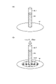
- FIG. 10 is an explanatory diagram of decomposition processing of oil in soil.
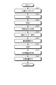
- FIG. 11 is a processing flow chart of decomposition processing of soil oil.
- FIG. 12 is an explanatory diagram of oil extraction processing after decomposition.
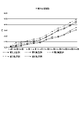
- FIG. 13 is an explanatory diagram of the soil oil decomposition test results.
- FIG. 1 is an explanatory diagram of a method for producing an oil-treated carrier according to an embodiment.
- oil-degrading bacteria are collected at the site of oil treatment (step S11), and cultured in a predetermined culture medium (step S12).
- oil-degrading bacteria that are suitable for the surrounding environment, it can be expected to further increase the oil-degrading capacity. Since culturing takes a certain amount of time, it is also possible to use oil-degrading bacteria that have been collected in an environment that is more similar to the local environment and have been cultured in advance. In this case, the oil-degrading bacteria collected and cultured at the site may be added for treatment.
- a porous substrate having air permeability and water permeability (permeability) is produced (step S13).
- waste glass is used to create a porous substrate.
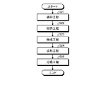
- FIG. 2 is an explanatory diagram of a method for producing a porous substrate.
- waste glass is crushed using a glass crusher (crusher) (step S21).
- the crushed waste glass is put into a glass crusher (granulator) and crushed to a predetermined particle size (step S22).
- a predetermined foaming agent or the like is added to the crushed waste glass, and the mixture is fired in a continuous firing furnace at a predetermined temperature for a predetermined time so as to have a desired specific gravity and strength (step S23).
- the desired specific gravity is 0.8 or more and 0.9 or less when the oil treatment carrier is used on the water surface, and 1.1 or more when the oil treatment carrier is used on the bottom of the water. be done.
- the desired strength is, for example, a strength that does not easily break due to waves or other influences when the oil treatment carrier is spread and left standing. Furthermore, even when oil treatment carriers (foam glass) come into contact with each other or other hard objects such as rocks, the strength is such that the shape can be maintained to some extent for a predetermined period of time.
- a strength that can maintain the shape of the oil-treated carrier to some extent during the scheduled recovery period. is. It should be noted that it is not limited to these, as long as it has a strength capable of maintaining the shape and function sufficient for the intended oil treatment for a predetermined period of time.
- by optimizing the type and amount of foaming agent added and adjusting the baking time to make the internal pores more continuous and to reduce the number of independent pores it is possible to improve air permeability and water permeability.
- the oil treatment carrier is used floating on the surface of water, it is prepared so as to leave appropriate independent pores in order to prevent sinking due to a decrease in buoyancy due to excessive water penetration.
- the obtained fired glass is molded into a predetermined size (diameter) or less by a molding device to form a porous substrate (step S24). Then, it is classified according to the application to be described later to obtain a porous substrate having a desired size (step S25).
- the porous substrate is formed as foamed glass whose main component is silicon dioxide (SiO 2 ), which exists most abundantly in nature. Therefore, unlike resin-made porous substrates, it does not cause the generation of microplastics and the like, so it does not become a source of pollution in the ocean, etc., and is an environmentally friendly material.
- SiO 2 silicon dioxide
- the cultured oil-degrading bacteria are supported on the prepared porous substrate (step S14).
- the sterilized porous substrate is immersed in a container containing oil-degrading bacteria and a nutrient solution of oil-degrading bacteria at a predetermined temperature for a predetermined time at a predetermined temperature suitable for culturing oil-degrading bacteria.
- oil-degrading bacteria adhere to the pores and surfaces of the porous substrate.
- the porous base material to which the oil-degrading bacteria are adhered is taken out from the container and left to stand still.
- the porous base material is placed again in the container containing the oil-degrading bacteria and the nutrient solution of the oil-degrading bacteria, and immersed for a predetermined time at a predetermined temperature suitable for culturing the oil-degrading bacteria to make the oil-degrading bacteria more porous. After depositing in the pores and on the surface of the substrate, it is drained.
- the porous substrate taken out of the container is left in an incubator at a predetermined temperature suitable for the oil-degrading bacteria to be supported, and for a predetermined time, colonies of oil-degrading bacteria are formed in the pores and on the surface of the porous substrate. (Colonies; cell clumps) are formed (colonization of oil-degrading bacteria) to form oil-treated carriers (step S15).
- the oil treatment carrier of this application is basically used outdoors, so it is assumed that it will be sprayed alone.
- mesh containers such as stainless steel (mesh containers) and mesh bags are filled with oil treatment carriers that carry oil-degrading bacteria, and the position where oil comes in contact is You can also set it to Also in this case, from the viewpoint of generating microplastics, it is desirable that the mesh container and the mesh bag are non-resin-based.
- FIG. 3 is a schematic explanatory diagram of the first embodiment.
- the first embodiment is an embodiment for treating oil floating and spreading on the surface of water such as oceans and rivers.
- the specific gravity of the porous base material 10A constituting the oil treatment carrier 10 is 0.8 or more and 0.9 or less. This is so that the oil treatment carrier 10 floats like an iceberg with its upper part protruding above the water surface.
- the oil-degrading bacteria 10B used in the present application are aerobic bacteria, the size (diameter) T1 of the thin portion of the oil treatment carrier 10 is set to be larger than the thickness T2 of the oil film OF to be treated. be.
- the oil-degrading bacteria 10B used in the present application are aerobic bacteria, the size (diameter) T1 of the thin portion of the oil treatment carrier 10 is set to be larger than the thickness T2 of the oil film OF to be treated. be.
- part of the upper surface of the oil treatment carrier 10 is positioned (protrudes) into the atmosphere above the oil film OF, and part of the lower surface of the oil treatment carrier 10 is positioned above the oil film OF. will be positioned (protruded) in the water WA below (sea water or fresh water).
- the specific surface area of the porous substrate 10A is more preferably 4.0 m 2 /g or more, more preferably 5.0 m 2 /g or more, and 10 m 2 /g or more. is more preferred, 20 m 2 /g or more is particularly preferred, and 40 m 2 /g or more is most preferred. Therefore, it is preferable to use a material with a larger specific surface area based on a manufacturing method corresponding to the properties (specific gravity, size, etc.) of the porous substrate 10A defined according to the purpose of use of the oil treatment carrier 10.
- the oil treatment carrier 10 of the first embodiment has gas and liquid permeability, that is, air permeability and water permeability, the porous base material 10A of the oil treatment carrier 10 It is possible for the oil-degrading bacteria 10B carried in the septum to utilize oxygen in the atmosphere and nutrients and water from water required for the oil-degrading treatment.
- oil decomposition may stop.
- oxygen is supplied to the oil-degrading bacteria 10B supported on the porous base material 10A even when the oil covers the water surface. 10B activities continue.
- the oil-degrading bacteria 10B can quickly perform the oil-degrading treatment over a long period of time compared to the case where oxygen, nutrients and water are not sufficiently obtained.
- oil films oil floating in wastewater treatment facilities such as seas, rivers, ponds, lakes, marshes, factories, etc. over a long period of time.
- This second embodiment is an embodiment for treating oil that has sunk to the bottom of water such as the bottom of the sea, the bottom of a river, or the bottom of a lake.
- the specific gravity of the porous base material 10A constituting the oil treatment carrier 10 is set to 1.1 or more. This is to ensure that the oil treatment carrier 10 sinks to the bottom of the water.
- the porous substrate 10A have the same specific surface area as in the first embodiment.
- an air diffuser to supply oxygen necessary for the activity or growth of the oil-degrading bacteria 10B.
- the size of the porous base material 10A is preferably 100 mm or less from the viewpoint of ease of handling and the effective amount of the oil-degrading bacteria 10B supported per unit weight. This is because it is thought that if the length exceeds 100 mm, the effective contact area and contact time of the carried oil-degrading bacteria will decrease, resulting in a decrease in treatment capacity. Furthermore, it is more preferably 0.15 mm or more and 50 mm or less, further preferably 1 mm or more and 35 mm or less, even more preferably 1 mm or more and 25 mm or less, and particularly preferably 1 mm or more and 10 mm or less.
- the reason for setting it to 0.15 mm or more is that if it is too fine, it will only be suspended without sinking, and the specific surface area of the porous substrate 10A will be small, and the amount of oil treatment bacteria carried, and eventually, This is because the oil cracking capacity per unit weight of the carrier for oil treatment is lowered.
- the size of the porous substrate 10A is relatively small, it is possible to increase the amount of oil-degrading bacteria supported per unit weight, that is, the size of the colony of oil-degrading bacteria, compared to the case of a relatively large size.
- the oil decomposition ability can be improved.
- the size of the porous substrate 10A is small, it will be blown away by the wind or washed away by the water flow, so it is necessary to set an optimum size according to the object to be treated.
- the second embodiment it is possible to efficiently decompose oil that has sunk in wastewater treatment facilities such as oceans, rivers, ponds, lakes, marshes, and factories. Further, in this case, if a sufficient amount of oxygen is supplied from water, the oil can be decomposed for a long period of time.
- the oil leaks to the soil on land, as in the case of treating oil adhering to waterside plants, stones, earth and sand, etc.
- This is an embodiment for treating spilled oil, oil in an oil tank such as a gasoline tank, or a case where waste oil from a factory, an oil treatment facility, or the like directly flows into the soil.
- the oil treatment carrier 10 is directly sprayed on a waterside such as a seashore, a river bank, or the like, or is mixed into the soil.
- the specific gravity of the porous base material 10A constituting the oil treatment carrier 10 is set to 1.1 or more. This is to make it difficult for the dispersed oil treatment carrier 10 to flow due to waves or flooding of rivers.
- the shape of the carrier for oil treatment is not particularly limited, but the size is preferably 35 mm or less, more preferably 10 mm or less, from the viewpoints of ease of handling, effective surface area, spreadable area per unit weight, etc. 3 mm or less is more preferable.
- the reason for such a size is that the oil treatment carrier 10 can easily enter the gaps between stones and sands and easily come into contact with the oil, thereby further improving the effect.
- an appropriate size is selected in order to prevent the particles from being blown up by the wind and scattered.
- the specific surface area of the porous base material 10A is more preferably 4.0 m 2 /g or more, further preferably 5.0 m 2 /g or more, further preferably 10 m 2 /g, from the viewpoint of effective oil decomposition treatment capacity.
- the above is more preferable, 20 m 2 /g or more is particularly preferable, and 40 m 2 /g or more is most preferable. That is, the larger the specific surface area, the larger the amount of oil-degrading bacteria supported per unit weight, that is, the larger the colony size of the oil-degrading bacteria, and the greater the oil-degrading ability.
- Example for treating oil on the surface of water First, an example for treating oil floating on the surface of water will be described.
- oil to be treated floats on the surface of seawater (salt water).
- seawater salt water
- 200 mL of artificial seawater and 15 mL of oil are put in a commercially available beaker, and the oil-degrading bacteria 10B extracted and cultured from the seawater are supported on the foam glass as the porous substrate 10A, and the oil-degrading bacteria are colonized.
- the treated oil-treated carrier 10 was floated on the water surface.
- FIG. 4 is a diagram showing changes in the amount of oil in the first embodiment and the first comparative example.
- the amount of oil fluctuates over time, but it is considered that the fluctuation is within the measurement error range.
- the amount of oil was calculated from the opening area of the beaker, the thickness of the oil film, and the previously obtained volume of the foamed glass as the porous base material 10A constituting the oil treatment carrier 10 .
- Second Example and Second Comparative Example oil to be treated floats on the surface of fresh water.
- 200 mL of pure water and 15 mL of oil are placed in a commercially available beaker, and oil-degrading bacteria 10B extracted and cultured from seawater are supported on foam glass as the porous substrate 10A.
- the converted oil treatment carrier 10 was floated on the water surface.
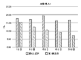
- FIG. 5 is a diagram showing changes in the amount of oil in the second embodiment and the second comparative example.
- the amount of oil fluctuates over time, but it is considered that the fluctuation is within the measurement error range.
- the amount of oil was calculated from the opening area of the beaker, the thickness of the oil film, and the volume of the foamed glass as the porous substrate 10A constituting the carrier 10 for oil treatment obtained in advance. As shown in FIG. 5, even in pure water (fresh water), more oil-degrading bacteria were supported on the foam glass as the porous substrate 10A than in the second comparative example in which only the cultured oil-degrading bacteria were added. It became clear that decomposition of oil proceeded more efficiently in the second example.
- 200 mL of artificial seawater and 15 mL of oil are put in a commercially available beaker, and the oil-degrading bacteria 10B extracted and cultured from the seawater are supported on the foam glass as the porous substrate 10A, and the oil-degrading bacteria are colonized.
- the treated oil-treated carrier 10 was floated on the water surface.
- 200 mL of artificial seawater and 15 mL of oil were placed in a commercially available beaker, and only the culture solution (15 mL) of oil-degrading bacteria was added.
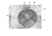
- FIG. 6 is a state explanatory diagram of the third embodiment.
- the size of the foamed glass as the porous substrate 10A was ⁇ 10 mm to ⁇ 35 mm, and a total of 10 g was used per one beaker BK.
- a plurality of oil treatment carriers 10 are floating on the sea surface in the beaker BK so as to push the oil OL away.
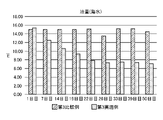
- FIG. 7 is a diagram showing changes in the amount of dissolved oxygen in water in the third example and the third comparative example.
- the amount of dissolved oxygen in water was detected from the 1st day to the 50th day using a digital dissolved oxygen meter DO-5509 manufactured by Mother Tool Co., Ltd.
- FIG. 8 is a diagram showing changes in the amount of oil in the third embodiment and the third comparative example. Again, the amount of oil was calculated from the opening area of the beaker, the thickness of the oil film, and the volume of the foamed glass as the porous base material 10A constituting the carrier 10 for oil treatment obtained in advance.
- the oil treatment carrier 10 of the fourth embodiment floats so as to push the oil away on the water surface.
- the change in the amount of dissolved oxygen in water in the fourth example and the fourth comparative example is the same as in the third example and the third comparative example. Oxygen was supplied, and it was confirmed that the amount of dissolved oxygen, which had once decreased, returned to its original level.
- FIG. 9 is a diagram showing changes in the amount of oil in the fourth embodiment and the fourth comparative example.
- the amount of oil was calculated from the opening area of the beaker, the thickness of the oil film, and the volume of the foamed glass as the porous substrate 10A constituting the carrier 10 for oil treatment obtained in advance.
- the oil-degrading bacteria are supported on the foam glass as the porous substrate 10A, only the cultured oil-degrading bacteria were added in pure water (fresh water) as shown in FIG. It was found that the decomposition of oil proceeded more efficiently than in the fourth comparative example.
- the amount of oil is higher than that of the first to fourth comparative examples. It was found that decomposition proceeded efficiently. Further, according to the first and second examples, it was found that the oil decomposition treatment proceeded efficiently by using the oil treatment carrier 10 of the example in either seawater (salt water) or freshwater. rice field. Therefore, it was found that oil decomposition treatment can be efficiently performed not only on the sea surface but also on the surface of water such as rivers.
- the oil treatment carrier 10 in either seawater (salt water) or freshwater, oxygen is supplied to the water, and oil-degrading bacteria are supplied from the water. It was found that the necessary nutrients and water could be supplied to 10B, and it was found that the oil decomposition process could be continued over a longer period of time.
- FIG. 10 is an explanatory diagram of decomposition processing of oil in soil. Further, FIG. 11 is a processing flow chart of decomposition processing of oil in soil.
- a soil sample of, for example, a diameter of 10 mm and a length of 30 mm is collected at a plurality of sampling locations (in the example of FIG. Locations SP1 to SP5: 150 mm in total) are sampled (step S11).
- step S12 the collected soils are mixed in a crucible (step S12), placed in an oven, and dried at 120° C. for 24 hours (step S13). After drying, the dry weight W1 is measured (step S14).
- FIG. 12 is an explanatory diagram of oil extraction processing after decomposition. Subsequently, as shown in FIG. 12A, a predetermined amount of the dried soil sample is filled in the glass tube GLT, and one end of the glass tube GLT is pressed against the center of the filter paper FP. Then, as shown in FIG. 12B, a predetermined amount of thinner is introduced from the open end of the glass tube GLT (step S15).
- the oil before decomposition does not dissolve in the thinner, but when it is decomposed, it dissolves in the thinner. Therefore, when the oil is decomposed and eluted into the thinner, the decomposed oil EXO seeps into the filter paper FP as the thinner flows out from the glass tube GLT on the filter paper FP side, as shown in FIG. 12(B). , the filter paper FP is circularly colored.
- the colored area is proportional to the amount of decomposed oil EXO, so for reference, the colored area (the area of the circle) of the filter paper is calculated (step S16). Subsequently, the soil sample after oil extraction is placed in a new crucible and placed in an oven to dry for 24 hours (step S17).
- soil samples are taken from the soil SAR at predetermined sampling timings (step S11), and the processing of steps S12 to S19 is repeated.
- FIG. 13 is an explanatory diagram of the soil oil decomposition test results.
- a comparative example (control) for the soil oil decomposition test a fifth comparative example was used in which a predetermined amount of oil was only sprinkled on a predetermined area of the soil SO.
- a predetermined amount of oil was spread over a predetermined area of soil, and then the oil treatment carrier was spread over the surface of the soil.
- the amount of oil treatment carrier applied was 10 g per kg of soil (56 g total).
- a predetermined amount of oil treatment carrier is sprinkled on the surface of the soil of a predetermined area, the soil on the soil surface and the oil treatment carrier are mixed, and then a predetermined amount of oil is applied to the surface of the soil. sprayed. Furthermore, as a seventh example, a predetermined amount of oil was sprinkled on a predetermined area of soil, the oil on the surface of the soil was mixed with the oil, and then the oil treatment carrier was sprinkled on the surface of the soil.
- a predetermined amount of oil is sprinkled on a predetermined area of soil, and after mixing the oil sprinkled on the soil on the surface of the soil, an oil treatment carrier is further sprinkled on the surface of the soil, and the surface of the soil is The soil and oil treatment carrier were mixed together.
- the soil was sampled every 3 or 4 days to determine the amount of oil decomposition.
- the cumulative amount of oil decomposition was about 3 ml in the fifth comparative example.
- a significant difference was observed. In particular, it was found that a greater effect was obtained when the soil on the surface of the soil and the carrier for oil treatment were mixed. Therefore, when removing oil that actually polluted the soil, it is effective to mix the oil treatment carrier into the soil.
Landscapes
- Life Sciences & Earth Sciences (AREA)
- Engineering & Computer Science (AREA)
- Chemical & Material Sciences (AREA)
- Microbiology (AREA)
- Organic Chemistry (AREA)
- Environmental & Geological Engineering (AREA)
- Hydrology & Water Resources (AREA)
- Biodiversity & Conservation Biology (AREA)
- General Engineering & Computer Science (AREA)
- Water Supply & Treatment (AREA)
- Health & Medical Sciences (AREA)
- Bioinformatics & Cheminformatics (AREA)
- Genetics & Genomics (AREA)
- Wood Science & Technology (AREA)
- Zoology (AREA)
- General Health & Medical Sciences (AREA)
- Biochemistry (AREA)
- Biotechnology (AREA)
- Biomedical Technology (AREA)
- Inorganic Chemistry (AREA)
- Mechanical Engineering (AREA)
- Civil Engineering (AREA)
- Structural Engineering (AREA)
- Biological Treatment Of Waste Water (AREA)
- Treatment Of Biological Wastes In General (AREA)
- Purification Treatments By Anaerobic Or Anaerobic And Aerobic Bacteria Or Animals (AREA)
- Cleaning Or Clearing Of The Surface Of Open Water (AREA)
- Immobilizing And Processing Of Enzymes And Microorganisms (AREA)
Abstract
実施形態の油処理担体は、気体及び液体の通過性を有し、油分解菌を担持した多孔質基材を備えるので、水面に拡散したり、ムース化して水中あるいは水底に沈降したりした油、または土壌中に流出した油の処理を促進し、かつ、油処理担体による環境への影響を低減する。
Description
本発明の実施形態は、油処理担体及び油処理方法に関する。
従来、海水や湖池沼などの水面上に流出した油は、周囲をオイルフェンス等で囲って油の拡散を防いだ後、吸着材や吸引により回収していた。
しかしながら、すべての油を回収しきることはできず、残った油は水面に薄く拡散したり、ムース化して水中に沈降したりすることとなっていた。
これらの回収できなかった油はいずれ微生物によって分解されていくこととなる。しかしながら、回収できなかった油が、完全に分解されるには長期間を要することとなり、環境への影響が大きくなっていた。
また、陸上においても工場などから土壌へ漏洩、流出した油は、吸着材や吸引での回収が難しく、土壌の入れ替えなどにより処理されている。しかしながら、処理費用が高いことが課題となっていた。
しかしながら、すべての油を回収しきることはできず、残った油は水面に薄く拡散したり、ムース化して水中に沈降したりすることとなっていた。
これらの回収できなかった油はいずれ微生物によって分解されていくこととなる。しかしながら、回収できなかった油が、完全に分解されるには長期間を要することとなり、環境への影響が大きくなっていた。
また、陸上においても工場などから土壌へ漏洩、流出した油は、吸着材や吸引での回収が難しく、土壌の入れ替えなどにより処理されている。しかしながら、処理費用が高いことが課題となっていた。
ところで、回収しきれなかった油のうち、水面に残って拡散した油においては、あらかじめ大量培養した油分解菌を水面に撒布したり、油分解菌を担持させた樹脂製担体を同じく水面に散布したりすることで分解時間を短縮させる技術が提案されている。
しかしながら、分解速度が充分ではなかったり、油分解菌を担持させる担体が樹脂製であるためマイクロプラスチック発生の原因となったりするなどの課題があった。
また水底に沈んだ油や水辺に漂着した油は、吸着材や吸引での回収が難しく、これらの効率的な除去が課題となっていた。
しかしながら、分解速度が充分ではなかったり、油分解菌を担持させる担体が樹脂製であるためマイクロプラスチック発生の原因となったりするなどの課題があった。
また水底に沈んだ油や水辺に漂着した油は、吸着材や吸引での回収が難しく、これらの効率的な除去が課題となっていた。
本発明は、上記に鑑みてなされたものであって、水面に拡散したり、ムース化して水中又は水底に沈降したり、あるいは、土壌に流出したりした油の処理を促進し、かつ、油処理担体による環境への影響を低減する油処理担体及び油処理方法を提供することを目的としている。
実施形態の油処理担体は、気体及び液体の通過性を有し、油分解菌を担持した多孔質基材を備える。
また、実施形態の油処理方法は、気体及び液体の通過性を有し、油分解菌を担持した多孔質基材を備えた油処理担体が、処理対象水域の水面に浮かんだ処理対象の油膜の表面から大気中に突出するとともに、油膜の下面側から水中に突出するように前記油処理担体の大きさを選定する過程と、選定した油処理担体を処理対象の油膜上に撒布する過程と、を備える。
次に実施形態について図面を参照して詳細に説明する。
図1は、実施形態の油処理担体の製造方法の説明図である。
まず、油処理を行う現地で油分解菌を採集し(ステップS11)、所定の培養液で培養を行う(ステップS12)。
図1は、実施形態の油処理担体の製造方法の説明図である。
まず、油処理を行う現地で油分解菌を採集し(ステップS11)、所定の培養液で培養を行う(ステップS12)。
これは周囲環境に適した油分解菌を得ることにより、より油分解処理能力を高めることが期待できるからである。なお、培養にはそれなりの時間がかかるので、現地の環境により似ている環境で採取され、予め培養された油分解菌を用いて処理を先行して行うようにすることも可能である。この場合には、さらに現地で採集して培養した油分解菌を追加で投入して処理を行うようにすれば良い。
油分解菌の採集及び培養と並行して、通気性及び通水性(通過性)を有する多孔質基材の作成を行う(ステップS13)。
本実施形態においては、廃ガラスを用いて多孔質基材の作成を行っている。
本実施形態においては、廃ガラスを用いて多孔質基材の作成を行っている。
図2は、多孔質基材の作成方法の説明図である。
まず多孔質基材を作成するに当たっては、廃ガラスをガラス破砕機(クラッシャ)を用いて破砕する(ステップS21)。
続いて、破砕した廃ガラスをガラス粉砕機(グラニュレータ)に投入して所定粒度となるように粉砕する(ステップS22)。
まず多孔質基材を作成するに当たっては、廃ガラスをガラス破砕機(クラッシャ)を用いて破砕する(ステップS21)。
続いて、破砕した廃ガラスをガラス粉砕機(グラニュレータ)に投入して所定粒度となるように粉砕する(ステップS22)。
続いて、粉砕した廃ガラスに所定の発泡剤などを加えて、連続式の焼成炉により、所望の比重、強度を有するように所定の温度で所定時間の間焼成する(ステップS23)。
この場合において、所望の比重とは、油処理担体を水面で用いる場合には、比重0.8以上0.9以下とされ、油処理担体を水底で用いる場合には、比重1.1以上とされる。これらの理由については、後に詳述する。
また、所望の強度とは、たとえば、油処理担体を撒布して、放置した状態において、波、その他の影響等を受けて容易に壊れることない強度である。さらには油処理担体(発泡ガラス)同士が接触したり、岩等の他の硬いものと接触した場合でも、所定期間ある程度の形状を維持することが可能な強度である。また、油処理担体の回収の必要がある場合には、回収時に細かくなりすぎて未回収となる油処理担体の量を抑制すべく、回収予定期間において、油処理担体の形状をある程度維持できる強度である。なお、これらに限らず、目的の油処理を行うのに十分な形状及び機能を所定期間維持可能な強度を有していればよい。
また、発泡剤の種類や添加量の最適化、焼成時間を調整して内部の気孔をより連続的にし、独立気孔を少なくすることで、通気性及び通水性を向上させることが可能となっている。この場合において、油処理担体を水面に浮かべて用いる場合には、水が浸透しすぎて浮力が低下し、沈んでしまうのを防止するため、独立気孔を適宜残すように調製する。
また、所望の強度とは、たとえば、油処理担体を撒布して、放置した状態において、波、その他の影響等を受けて容易に壊れることない強度である。さらには油処理担体(発泡ガラス)同士が接触したり、岩等の他の硬いものと接触した場合でも、所定期間ある程度の形状を維持することが可能な強度である。また、油処理担体の回収の必要がある場合には、回収時に細かくなりすぎて未回収となる油処理担体の量を抑制すべく、回収予定期間において、油処理担体の形状をある程度維持できる強度である。なお、これらに限らず、目的の油処理を行うのに十分な形状及び機能を所定期間維持可能な強度を有していればよい。
また、発泡剤の種類や添加量の最適化、焼成時間を調整して内部の気孔をより連続的にし、独立気孔を少なくすることで、通気性及び通水性を向上させることが可能となっている。この場合において、油処理担体を水面に浮かべて用いる場合には、水が浸透しすぎて浮力が低下し、沈んでしまうのを防止するため、独立気孔を適宜残すように調製する。
続いて得られた焼成ガラスを成形装置により所定の大きさ(径)以下に成形して多孔質基材とする(ステップS24)。
そして、後述する用途に応じて分級して、所望の大きさを有する多孔質基材とする(ステップS25)。
そして、後述する用途に応じて分級して、所望の大きさを有する多孔質基材とする(ステップS25)。
ここで、多孔質基材の化学組成の一例について説明する。
表1に示すように、多孔質基材は、自然界で最も大量に存在する二酸化ケイ素(SiO2)を主成分とする発泡ガラスとして形成されている。
従って、樹脂製の多孔質基材と異なり、マイクロプラスチック等の発生原因となることもないので、海洋等の汚染源とはならず、環境に優しい素材である。
表1に示すように、多孔質基材は、自然界で最も大量に存在する二酸化ケイ素(SiO2)を主成分とする発泡ガラスとして形成されている。
従って、樹脂製の多孔質基材と異なり、マイクロプラスチック等の発生原因となることもないので、海洋等の汚染源とはならず、環境に優しい素材である。

続いて、培養した油分解菌を、作成した多孔質基材に担持させる(ステップS14)。
滅菌した多孔質基材を所定温度で油分解菌及び油分解菌の栄養溶液を入れた容器中で油分解菌の培養に適した所定温度で所定時間浸漬する。
これにより多孔質基材の孔内及び表面には、油分解菌が付着する。
滅菌した多孔質基材を所定温度で油分解菌及び油分解菌の栄養溶液を入れた容器中で油分解菌の培養に適した所定温度で所定時間浸漬する。
これにより多孔質基材の孔内及び表面には、油分解菌が付着する。
そして、油分解菌を付着させた多孔質基材を容器から取り出した後、静置する。その後再び多孔質基材を油分解菌及び油分解菌の栄養溶液を入れた容器中に入れ、油分解菌の培養に適した所定温度で所定時間浸漬することで、より油分解菌を多孔質基材の孔内及び表面に付着させた後、排水する。
その後、容器から取り出した多孔質基材をインキュベーター内にて、担持させる油分解菌に適した所定温度、所定時間静置することで、多孔質基材の孔内及び表面で油分解菌のコロニー(集落;細胞集塊)が形成(油分解菌コロニー化)されることで油処理担体とする(ステップS15)。
その後、容器から取り出した多孔質基材をインキュベーター内にて、担持させる油分解菌に適した所定温度、所定時間静置することで、多孔質基材の孔内及び表面で油分解菌のコロニー(集落;細胞集塊)が形成(油分解菌コロニー化)されることで油処理担体とする(ステップS15)。
以上の説明のように、使用態様に応じて多孔質基材の比重や粒径を調整することで、より効率的に油分を分解可能な油処理担体を作成できる。
本願の油処理担体は、基本的には、屋外で使用するため、単体で撒布することを前提としている。しかしながら、工場排水処理施設等の油分を分解する場合は、ステンレスなどのメッシュ状の容器(メッシュ容器)、メッシュ袋に油分解菌を担持させた油処理担体を充填して、油と接触する位置に設置するようにしても良い。この場合においても、マイクロプラスチック発生の観点から、メッシュ容器、メッシュ袋は非樹脂系のものとするのが望ましい。
次に実施形態についてより詳細に説明する。
[1]第1実施形態(水面処理)
図3は、第1実施形態の概要説明図である。
本第1実施形態は、海洋や河川等の水面に浮いて拡散している油の処理を行う場合の実施形態である。
[1]第1実施形態(水面処理)
図3は、第1実施形態の概要説明図である。
本第1実施形態は、海洋や河川等の水面に浮いて拡散している油の処理を行う場合の実施形態である。
この場合において、油処理担体10を構成している多孔質基材10Aの比重は、0.8以上0.9以下とされる。これは、油処理担体10が氷山のように水面から上部が突出した状態で、浮いているようにするためである。
さらに本願で用いる油分解菌10Bは、好気性菌であるため、油処理担体10の薄い部分の大きさ(径)T1は、処理対象の油膜OFの厚さT2よりも大きくなるように設定される。
この結果、図3に示すように、油処理担体10の上面の一部は、油膜OFよりも上方の大気中に位置(突出)し、油処理担体10の下面の一部は、油膜OFよりも下方の水WAの中(海水中あるいは淡水中)に位置(突出)することとなる。
この結果、図3に示すように、油処理担体10の上面の一部は、油膜OFよりも上方の大気中に位置(突出)し、油処理担体10の下面の一部は、油膜OFよりも下方の水WAの中(海水中あるいは淡水中)に位置(突出)することとなる。
また、多孔質基材10Aの比表面積は、大きければ大きいほど担持できる油分解菌が多くなるので、多孔質基材10Aの比表面積は、3.0m2/g以上であることが望ましい。
さらには、油分解菌の担持量の観点から、多孔質基材10Aの比表面積は、4.0m2/g以上がより好ましく、5.0m2/g以上がさらに望ましく、10m2/g以上がより一層好ましく、20m2/g以上が特に好ましく、40m2/g以上が最も好ましい。
したがって、油処理担体10の使用目的に応じて規定される多孔質基材10Aの性状(比重、大きさ等)に対応する製造方法に基づいて、より比表面積の大きな材料を用いるのが好ましい。
したがって、油処理担体10の使用目的に応じて規定される多孔質基材10Aの性状(比重、大きさ等)に対応する製造方法に基づいて、より比表面積の大きな材料を用いるのが好ましい。
以上に説明したように、本第1実施形態の油処理担体10は、気体及び液体の通過性、すなわち、通気性及び通水性を有しているので、油処理担体10の多孔質基材10Aに担持された油分解菌10Bが油分解処理に必要とする大気中の酸素及び水中からの栄養分及び水分を利用することが可能となる。
例えば、水面に油が拡散して油膜OFを形成した場合、油膜大気中の酸素が水中に溶け込むのを油が阻害してしまう。このため、仮に油処理担体10の油分解菌10Bが水中の酸素を使い切る(あるいは、分解に十分ではない酸素量となる)と、油分解が停止してしまう可能性がある。これに対して、本実施形態の油処理担体10によれば、油が水面を覆ってしまった場合でも多孔質基材10Aに担持されている油分解菌10Bに酸素が供給され、油分解菌10Bの活動が継続される。
したがって、油分解菌10Bが酸素、栄養分及び水分が十分に得られない場合と比較して長期にわたり、油分解処理を迅速に行うことができる。
すなわち、本第1実施形態によれば、海や河川、池、湖、沼、工場等の廃水処理施設内に浮かんだ油膜(油)の分解処理を迅速に、長期にわたって行うことができる。
[2]第2実施形態
本第2実施形態は、海底、河底、湖底等の水底に沈んでしまった油の処理を行う場合の実施形態である。
この場合において、油処理担体10を構成している多孔質基材10Aの比重は、1.1以上とされる。これは、油処理担体10が確実に水底に沈むようにするためである。
この場合においては、油処理担体10、ひいては、多孔質基材10Aの形状には特に制限はない。
本第2実施形態は、海底、河底、湖底等の水底に沈んでしまった油の処理を行う場合の実施形態である。
この場合において、油処理担体10を構成している多孔質基材10Aの比重は、1.1以上とされる。これは、油処理担体10が確実に水底に沈むようにするためである。
この場合においては、油処理担体10、ひいては、多孔質基材10Aの形状には特に制限はない。
また、多孔質基材10Aの比表面積は、大きければ大きいほど担持できる油分解菌が多くなるので、第1実施形態と同様の比表面積を有するのが好ましい。
また、水底における酸素量が少ない場合は、散気装置を使用し、油分解菌10Bが活動あるいは、増殖するために必要な酸素供給を行うのが好ましい。
また、水底における酸素量が少ない場合は、散気装置を使用し、油分解菌10Bが活動あるいは、増殖するために必要な酸素供給を行うのが好ましい。
また、多孔質基材10Aの大きさは、取り扱いの容易さ、単位重量あたりの実効的な油分解菌10Bの担持量の観点から100mm以下が望ましい。100mmを超えると、担持されている油分解菌の実効的な接触面積及び接触時間が低下して、処理能力が低下すると考えられるためである。さらには、0.15mm以上50mm以下がより好ましく、1mm以上35mm以下がさらに好ましく、1mm以上25mm以下がより一層好ましく、1mm以上10mm以下が特に好ましい。この場合において、0.15mm以上としている理由は、あまり細かいと沈まずに懸濁するだけとなってしまうとともに、多孔質基材10Aの比表面積が小さくなり、油処理菌の担持量、ひいては、油処理担体の単位重量あたりの油分解処理能力が低下するからである。
すなわち、多孔質基材10Aの大きさが比較的小さければ、比較的大きい場合より単位重量あたりの油分解菌の担持量、すなわち、油分解菌のコロニーの大きさを大きくすることが可能となり、油分解能力の向上が図れる。一方、多孔質基材10Aの大きさが小さいと風により飛ばされたり、水流で流されたりしてしまうため、処理対象に応じて最適な大きさに設定する必要がある。
本第2実施形態によれば、海洋や河川、池、湖、沼、工場等の廃水処理施設内に沈んだ油の分解処理を効率的に行える。また、この場合には、水中からの酸素量の供給が十分であれば、長期にわたって、油の分解処理が行える。
特に海水によりムース化してオイルボールが生成し、海中に沈降した油であっても分解処理をおこなうことが可能となり、海洋汚染の影響を当該海域全体としてより低減することができる。
[3]第3実施形態
本第3実施形態は、海岸、川岸等の水辺において、水辺の植物や、石、土砂などに付着した油の処理を行う場合のように、陸上において土壌へ漏洩、流出した油の処理を行う場合や、ガソリンタンク等の油タンク内の油や、工場、油処理施設等からの廃油が直接土壌に流出した場合等の実施形態である。
この場合において、油処理担体10は海岸、川岸等の水辺において直接撒布したり、土壌に漉き込んだりするようにされる。
本第3実施形態は、海岸、川岸等の水辺において、水辺の植物や、石、土砂などに付着した油の処理を行う場合のように、陸上において土壌へ漏洩、流出した油の処理を行う場合や、ガソリンタンク等の油タンク内の油や、工場、油処理施設等からの廃油が直接土壌に流出した場合等の実施形態である。
この場合において、油処理担体10は海岸、川岸等の水辺において直接撒布したり、土壌に漉き込んだりするようにされる。
油処理担体10を構成している多孔質基材10Aの比重は、1.1以上とされる。これは、撒布した油処理担体10が波や、河川の増水で流れにくくするためである。
また油処理担体の形状には特に制限はないが、大きさは、取り扱いの容易さ、実効的な表面積、単位重量あたりの撒布可能面積などの観点から35mm以下が好ましく、10mm以下がより好ましく、3mm以下がさらに好ましい。このような大きさとするのは、油処理担体10が石や砂の隙間に入りやすく、油と接触しやすくなるためより効果が向上するからである。
なお、撒布環境によっては、風により舞い上がって、散ってしまうのを防止するため、適度な大きさが選択される。
なお、撒布環境によっては、風により舞い上がって、散ってしまうのを防止するため、適度な大きさが選択される。
また、多孔質基材10Aの比表面積は、大きければ大きいほど担持できる油分解菌が多くなるので、第1実施形態と同様に、多孔質基材10Aの比表面積は、3.0m2/g以上であることが望ましい。これは、3.0m2/g未満であると担持可能な油分解菌の量が低下し、実効的な処理能力が低下するからである。
さらには、多孔質基材10Aの比表面積は、実効的な油分解処理能力の観点から、4.0m2/g以上がより好ましく、5.0m2/g以上がさらに望ましく、10m2/g以上がより一層好ましく、20m2/g以上が特に好ましく、40m2/g以上が最も好ましい。
すなわち、比表面積が大きいほど単位重量あたりの油分解菌の担持量、すなわち、油分解菌のコロニーの大きさを大きくすることが可能となり、油分解能力の向上が図れる。
すなわち、比表面積が大きいほど単位重量あたりの油分解菌の担持量、すなわち、油分解菌のコロニーの大きさを大きくすることが可能となり、油分解能力の向上が図れる。
次により具体的な実施例について説明する。
[1]水面の油の処理に対応する実施例
まず、水面に浮いている油の処理を行う場合の実施例について説明する。
[1.1]第1実施例及び第1比較例
本第1実施例及び第1比較例は、海水(塩水)の水面に処理対象の油が浮いている状態のものである。
第1実施例として、市販のビーカーに人工海水200mLと油15mLを入れ、海水から抽出・培養した油分解菌10Bを、多孔質基材10Aとしての発泡ガラスに担持させ、油分解菌をコロニー化した油処理担体10を水面に浮かべた。
[1]水面の油の処理に対応する実施例
まず、水面に浮いている油の処理を行う場合の実施例について説明する。
[1.1]第1実施例及び第1比較例
本第1実施例及び第1比較例は、海水(塩水)の水面に処理対象の油が浮いている状態のものである。
第1実施例として、市販のビーカーに人工海水200mLと油15mLを入れ、海水から抽出・培養した油分解菌10Bを、多孔質基材10Aとしての発泡ガラスに担持させ、油分解菌をコロニー化した油処理担体10を水面に浮かべた。
また第1比較例として、市販のビーカーに人工海水200mLと油15mLを入れ、油分解菌の培養液(15mL)のみを投入した。
図4は、第1実施例及び第1比較例の油量の推移を示す図である。
図4において、第1比較例においては、時間経過に伴って油量が増減しているが、測定誤差範囲内における変動であると考えられる。
ここで、油量はビーカーの開口面積および油膜厚さ、予め求めた油処理担体10を構成している多孔質基材10Aとしての発泡ガラスの体積から算出した。
図4において、第1比較例においては、時間経過に伴って油量が増減しているが、測定誤差範囲内における変動であると考えられる。
ここで、油量はビーカーの開口面積および油膜厚さ、予め求めた油処理担体10を構成している多孔質基材10Aとしての発泡ガラスの体積から算出した。
図4に示すように、海水中において、培養した油分解菌のみを添加した第1比較例よりも、油分解菌を多孔質基材10Aとしての発泡ガラスに担持させた第1実施例の方が、油の分解が効率的に進行していることが明らかになった。
[1.2]第2実施例及び第2比較例
本第2実施例及び第2比較例は、淡水の水面に処理対象の油が浮いている状態のものである。
第2実施例として、市販のビーカーに純水200mLと油15mLを入れ、海水から抽出・培養した油分解菌10Bを、多孔質基材10Aとしての発泡ガラスに担持させた、油分解菌をコロニー化した油処理担体10を水面に浮かべた。
本第2実施例及び第2比較例は、淡水の水面に処理対象の油が浮いている状態のものである。
第2実施例として、市販のビーカーに純水200mLと油15mLを入れ、海水から抽出・培養した油分解菌10Bを、多孔質基材10Aとしての発泡ガラスに担持させた、油分解菌をコロニー化した油処理担体10を水面に浮かべた。
また第2比較例として、市販のビーカーに純水200mLと油15mLを入れ、油分解菌の培養液(15mL)のみを投入した。
図5は、第2実施例及び第2比較例の油量の推移を示す図である。
図5において、第2比較例においては、時間経過に伴って油量が増減しているが、測定誤差範囲内における変動であると考えられる。
図5において、第2比較例においては、時間経過に伴って油量が増減しているが、測定誤差範囲内における変動であると考えられる。
ここでも、油量は、ビーカーの開口面積および油膜厚さ、予め求めた油処理担体10を構成している多孔質基材10Aとしての発泡ガラスの体積から算出した。
図5に示すように、純水中(淡水中)においても、培養した油分解菌のみを添加した第2比較例よりも、油分解菌を多孔質基材10Aとしての発泡ガラスに担持させた第2実施例の方が、油の分解が効率的に進行していることが明らかになった。
図5に示すように、純水中(淡水中)においても、培養した油分解菌のみを添加した第2比較例よりも、油分解菌を多孔質基材10Aとしての発泡ガラスに担持させた第2実施例の方が、油の分解が効率的に進行していることが明らかになった。
[1.3]第3実施例及び第3比較例
本第3実施例及び第3比較例は、海水(塩水)の水面に処理対象の油が浮いている状態における海水中の溶存酸素量との関係を明らかにするための実施例及び比較例である。
本第3実施例及び第3比較例は、海水(塩水)の水面に処理対象の油が浮いている状態における海水中の溶存酸素量との関係を明らかにするための実施例及び比較例である。
第3実施例として、市販のビーカーに人工海水200mLと油15mLを入れ、海水から抽出・培養した油分解菌10Bを、多孔質基材10Aとしての発泡ガラスに担持させ、油分解菌をコロニー化した油処理担体10を水面に浮かべた。
また第3比較例として、市販のビーカーに人工海水200mLと油15mLを入れ、油分解菌の培養液(15mL)のみを投入した。
また第3比較例として、市販のビーカーに人工海水200mLと油15mLを入れ、油分解菌の培養液(15mL)のみを投入した。
図6は、第3実施例の状態説明図である。
図6の第3実施例においては、多孔質基材10Aとしての発泡ガラスの大きさはφ10mm~φ35mmとし、1ビーカーBKあたり計10g使用した。
図6に示すように、第3実施例においては、ビーカーBK内の海水面で油OLを押しのけるように、複数の油処理担体10が浮かんだ状態となっているのがわかる。
図6の第3実施例においては、多孔質基材10Aとしての発泡ガラスの大きさはφ10mm~φ35mmとし、1ビーカーBKあたり計10g使用した。
図6に示すように、第3実施例においては、ビーカーBK内の海水面で油OLを押しのけるように、複数の油処理担体10が浮かんだ状態となっているのがわかる。
また、図7は、第3実施例及び第3比較例における水中の溶存酸素量の推移を示す図である。
第3実施例及び第3比較例においては、株式会社マザーツール社製のデジタル溶存酸素計DO-5509により水中の溶存酸素量を第1日~第50日にわたって検出した。
第3実施例及び第3比較例においては、株式会社マザーツール社製のデジタル溶存酸素計DO-5509により水中の溶存酸素量を第1日~第50日にわたって検出した。
図7に示すように、海水面を油が覆っている場合であっても、多孔質基材10Aとしての発泡ガラスを通して酸素が供給され、第1日目から第7日目までに一度低下した溶存酸素量が7日目以降徐々に元に戻ることが確認できた。
したがって、実際の野外環境で油処理担体10を使用した場合にも、長期にわたって油分解能力を保持することが期待できる。
したがって、実際の野外環境で油処理担体10を使用した場合にも、長期にわたって油分解能力を保持することが期待できる。
また、図8は、第3実施例及び第3比較例の油量の推移を示す図である。
ここでも、油量はビーカーの開口面積および油膜厚さ、予め求めた油処理担体10を構成している多孔質基材10Aとしての発泡ガラスの体積から算出した。
ここでも、油量はビーカーの開口面積および油膜厚さ、予め求めた油処理担体10を構成している多孔質基材10Aとしての発泡ガラスの体積から算出した。
油分解菌を多孔質基材10Aとしての発泡ガラスに担持させた本第3実施例においても、図8に示すように、海水中において、培養した油分解菌のみを添加した第3比較例よりも、油の分解が効率的に進行していることが明らかになった。
[1.4]第4実施例及び第4比較例
本第4実施例及び第4比較例は、淡水の水面に処理対象の油が浮いている状態における淡水中の溶存酸素量との関係を明らかにするための実施例及び比較例である。
本第4実施例及び第4比較例は、淡水の水面に処理対象の油が浮いている状態における淡水中の溶存酸素量との関係を明らかにするための実施例及び比較例である。
第4実施例として、市販のビーカーに純水200mLと油15mLを入れ、海水から抽出・培養した油分解菌10Bを、多孔質基材10Aとしての発泡ガラスに担持させた後、乾燥させた油処理担体10を水面に浮かべた。
また第4比較例として、市販のビーカーに純水200mLと油15mLを入れ、油分解菌の培養液(15mL)のみを投入した。
この場合において、第4実施例においては、図6に示した第3実施例と同様に水面で油を押しのけるように第4実施例の油処理担体10が浮かんだ状態となっていた。
この場合において、第4実施例においては、図6に示した第3実施例と同様に水面で油を押しのけるように第4実施例の油処理担体10が浮かんだ状態となっていた。
また、第4実施例及び第4比較例における水中の溶存酸素量の推移は、第3実施例及び第3比較例と同様であり、淡水中において油が水面を覆っていても、発泡ガラスを通して酸素が供給され、一度低下した溶存酸素量が元に戻ってくることが確認できた。
図9は、第4実施例及び第4比較例の油量の推移を示す図である。
ここでも、油量は、ビーカーの開口面積および油膜厚さ、予め求めた油処理担体10を構成している多孔質基材10Aとしての発泡ガラスの体積から算出した。
油分解菌を多孔質基材10Aとしての発泡ガラスに担持させた本第4実施例においても、図9に示すように、純水中(淡水中)において、培養した油分解菌のみを添加した第4比較例よりも、油の分解が効率的に進行していることが明らかになった。
ここでも、油量は、ビーカーの開口面積および油膜厚さ、予め求めた油処理担体10を構成している多孔質基材10Aとしての発泡ガラスの体積から算出した。
油分解菌を多孔質基材10Aとしての発泡ガラスに担持させた本第4実施例においても、図9に示すように、純水中(淡水中)において、培養した油分解菌のみを添加した第4比較例よりも、油の分解が効率的に進行していることが明らかになった。
[1.5]第1実施例~第4実施例の効果
以上の説明のように、第1実施例乃至第4実施例のいずれにおいても、第1比較例乃至第4比較例よりも油の分解が効率的に進行していることがわかった。
また第1実施例及び第2実施例によれば、海水(塩水)あるいは淡水のいずれにおいても、実施例の油処理担体10を用いることで効率的に油分解処理が進行していることがわかった。従って海面に限らず、河川などの水面においても油分解処理を効率的に行えることがわかった。
以上の説明のように、第1実施例乃至第4実施例のいずれにおいても、第1比較例乃至第4比較例よりも油の分解が効率的に進行していることがわかった。
また第1実施例及び第2実施例によれば、海水(塩水)あるいは淡水のいずれにおいても、実施例の油処理担体10を用いることで効率的に油分解処理が進行していることがわかった。従って海面に限らず、河川などの水面においても油分解処理を効率的に行えることがわかった。
また第3実施例及び第4実施例によれば、海水(塩水)あるいは淡水のいずれにおいても、油処理担体10を用いることで、水中へは酸素を供給して、水中からは、油分解菌10Bに必要な栄養素及び水分を供給できることがわかり、より長期にわたって油分解処理を継続することができることがわかった。
したがって、第1実施例乃至第4実施例のいずれの実施例においても、対応する比較例と比較して、油処理に要する時間及び労力を低減できることがわかった。
[2]土壌の油の処理に対応する実施例
次に、土壌の油の処理を行う場合の実施例について説明する。
[2.1]土壌の油の分解処理の実施手順
まず、土壌の油の分解処理に対しての実施手順について説明する。
この場合において、分解された油の量を実験的に求めるのに先だって、所定面積の土壌に、所定量の油を撒布しておくものとする。
そして、撒布した油の分解前の比重DNは既知であるものとする。例えば、油100mlの重さを測定し、その重さが78.58gであった場合には、
DN=78.58/100
=0.7858g/ml
となる。
次に、土壌の油の処理を行う場合の実施例について説明する。
[2.1]土壌の油の分解処理の実施手順
まず、土壌の油の分解処理に対しての実施手順について説明する。
この場合において、分解された油の量を実験的に求めるのに先だって、所定面積の土壌に、所定量の油を撒布しておくものとする。
そして、撒布した油の分解前の比重DNは既知であるものとする。例えば、油100mlの重さを測定し、その重さが78.58gであった場合には、
DN=78.58/100
=0.7858g/ml
となる。
図10は、土壌の油の分解処理の説明図である。
また、図11は、土壌の油の分解処理の処理フローチャートである。
まず、図10に示すように、予め油を撒布した土壌SARから土壌採取器HDにより、例えば、直径10mm、長さ30mmの土壌サンプルを複数のサンプリング箇所(図10の例では、5箇所のサンプリング箇所SP1~SP5:合計150mm分)採取する(ステップS11)。
また、図11は、土壌の油の分解処理の処理フローチャートである。
まず、図10に示すように、予め油を撒布した土壌SARから土壌採取器HDにより、例えば、直径10mm、長さ30mmの土壌サンプルを複数のサンプリング箇所(図10の例では、5箇所のサンプリング箇所SP1~SP5:合計150mm分)採取する(ステップS11)。
続いて、採取した複数箇所の土をるつぼ中で混合し(ステップS12)、オーブンにるつぼを入れ、120℃で24時間乾燥する(ステップS13)。
乾燥後、乾燥重量W1を測定する(ステップS14)。
乾燥後、乾燥重量W1を測定する(ステップS14)。
図12は、分解後の油抽出処理の説明図である。
続いて乾燥した土壌サンプルを、図12(A)に示すように、所定量、ガラス管GLTに詰め、ガラス管GLTの一端を濾紙FPの中心部に押し当てた状態とする。
そして、図12(B)に示すように、所定量のシンナーをガラス管GLTの開放端から投入する(ステップS15)。
続いて乾燥した土壌サンプルを、図12(A)に示すように、所定量、ガラス管GLTに詰め、ガラス管GLTの一端を濾紙FPの中心部に押し当てた状態とする。
そして、図12(B)に示すように、所定量のシンナーをガラス管GLTの開放端から投入する(ステップS15)。
この場合において、分解前の油はシンナーに溶けないが、分解されるとシンナーに溶け出すこととなる。したがって、油が分解してシンナーに溶出すると、シンナーがガラス管GLTの濾紙FP側から流れ出るのにともなって、分解された油EXOが濾紙FPに染み出して、図12(B)に示すように、濾紙FPが円状に着色状態となる。
このとき、着色面積は、分解された油EXOの量に比例することとなるので、参考のため、濾紙の着色面積(円の面積)を算出する(ステップS16)。
続いて、油抽出後の土壌サンプルを新たなるつぼに入れ、オーブンに入れて、24時間乾燥する(ステップS17)。
続いて、油抽出後の土壌サンプルを新たなるつぼに入れ、オーブンに入れて、24時間乾燥する(ステップS17)。
乾燥後、抽出後乾燥重量W2を測定する(ステップS18)。
続いて、得られた乾燥重量W1[g]、抽出後乾燥重量W2[g]及び撒布した油の比重DN[g/ml]に基づいて、次式により、抽出した油量OA[ml]を算出する(ステップS19)。
OA=(W1-W2)/DN
続いて、得られた乾燥重量W1[g]、抽出後乾燥重量W2[g]及び撒布した油の比重DN[g/ml]に基づいて、次式により、抽出した油量OA[ml]を算出する(ステップS19)。
OA=(W1-W2)/DN
以降、所定のサンプリングタイミング毎に、土壌SARから土壌サンプルを採取し(ステップS11)、ステップS12~ステップS19の処理を繰り返す。
図13は、土壌油分解試験結果の説明図である。
土壌油分解試験の比較例(コントロール)として、所定面積の土壌SOに所定量の油を撒布しただけの第5比較例を用いた。
土壌油分解試験の比較例(コントロール)として、所定面積の土壌SOに所定量の油を撒布しただけの第5比較例を用いた。
この場合において、5リットルの土(重さ5.56kg)に対し、1kgの土に対して50mlの油(合計278ml)を撒布した。以下の実施例も同様である。
また第5実施例として、所定面積の土壌に所定量の油を撒布した状態で、油処理担体を当該土壌の表面に撒布した。
この場合において、撒布した油処理担体の量は、1kgの土に対して10g(合計56g)であった。
この場合において、撒布した油処理担体の量は、1kgの土に対して10g(合計56g)であった。
また、第6実施例として、所定の面積の土壌の表面に所定量の油処理担体を撒布し、土壌表面の土と油処理担体を混ぜ合わせ、その後、所定量の油を当該土壌の表面に撒布した。
さらに第7実施例として、所定面積の土壌に所定量の油を撒布し、土壌表面の土と油を混ぜ合わせた後、油処理担体を当該土壌の表面に撒布した。
さらに第7実施例として、所定面積の土壌に所定量の油を撒布し、土壌表面の土と油を混ぜ合わせた後、油処理担体を当該土壌の表面に撒布した。
さらにまた第8実施例として、所定面積の土壌に所定量の油を撒布し、土壌表面の土に撒布した油を混ぜ合わせた後、さらに油処理担体を当該土壌の表面に撒布し、土壌表面の土と油処理担体を混ぜ合わせるようにした。
図13に示すように、第5実施例は、油と油処理担体との実効的な接触面積が少ないと考えられるため、第5比較例(コントロール)よりは、分解量が多いが、短期間では、その効果は限定されていた。
これらに対し、第6実施例~第8実施例は、油と油処理担体との実効的な接触面積が十分であったため、初期から油分解処理能力が十分に発揮されていた。
これらに対し、第6実施例~第8実施例は、油と油処理担体との実効的な接触面積が十分であったため、初期から油分解処理能力が十分に発揮されていた。
さらに、第6実施例によれば、油の汚染の前に油の汚染の虞がある土壌(既汚染地域の近傍の土壌あるいは海流等により油が拡散するおそれがある海岸、河岸)等に予め油処理担体を撒布しておくことで、それらの影響を迅速に排除できることがわかった。
また、第7実施例及び第8実施例によれば、既に油の汚染があった土壌に対しても汚染初期あるいは所定時間が経過後であっても十分に油を分解することができることがわかった。
また、第7実施例及び第8実施例によれば、既に油の汚染があった土壌に対しても汚染初期あるいは所定時間が経過後であっても十分に油を分解することができることがわかった。
より具体的には、3,4日毎に土壌のサンプリングを行って、油の分解量を求めた。
この結果、徐々に油分解量の差が生じ、39日経過後において、油の累積分解量は、第5比較例がおよそ3mlであった。
この結果、徐々に油分解量の差が生じ、39日経過後において、油の累積分解量は、第5比較例がおよそ3mlであった。
これに対し、第5実施例では、油の累積分解量は、3.5ml(比較例との比率=1.17倍)、第6実施例では4.9ml(比較例との比率=1.63倍)、第7実施例では、4.3ml(比較例との比率=1.43倍)、第8実施例では、4.6ml(比較例との比率=1.53倍)、であり有意に差がみられた。
特に、土壌表面の土と油処理担体を混ぜ合わせるようにした場合、より大きな効果が得られることがわかった。
従って、実際に土壌を汚染した油の除去処理を行う際には、油処理担体を土壌中に漉き込むようにするのが効果的であることがわかる。
特に、土壌表面の土と油処理担体を混ぜ合わせるようにした場合、より大きな効果が得られることがわかった。
従って、実際に土壌を汚染した油の除去処理を行う際には、油処理担体を土壌中に漉き込むようにするのが効果的であることがわかる。
本発明のいくつかの実施形態を説明したが、これらの実施形態は、例として提示したものであり、発明の範囲を限定することは意図していない。これら新規な実施形態は、その他の様々な形態で実施されることが可能であり、発明の要旨を逸脱しない範囲で、種々の省略、置き換え、変更を行うことができる。これら実施形態やその変形は、発明の範囲や要旨に含まれるとともに、請求の範囲に記載された発明とその均等の範囲に含まれる。
Claims (12)
- 気体及び液体の通過性を有し、油分解菌を担持した多孔質基材を備えた油処理担体。
- 前記油分解菌は、前記多孔質基材上でコロニーを形成している、
請求項1に記載の油処理担体。 - 前記多孔質基材は、二酸化ケイ素を主成分とした無機材料で形成されている、
請求項1に記載の油処理担体。 - 前記多孔質基材は、発泡ガラスである、
請求項3に記載の油処理担体。 - 前記多孔質基材の比重は、0.8以上0.9以下である、
請求項1に記載の油処理担体。 - 前記多孔質基材の比重は、1.1以上である、
請求項1に記載の油処理担体。 - 前記多孔質基材の大きさは、100mm以下である、
請求項1に記載の油処理担体。 - 前記多孔質基材の大きさは、0.15mm以上50mm以下、1mm以上35mm以下、1mm以上25mm以下あるいは1mm以上10mm以下のいずれか一つである、
請求項7に記載の油処理担体。 - 前記多孔質基材の比表面積は、3.0m2/g以上である、
請求項1に記載の油処理担体。 - 前記多孔質基材の比表面積は、4.0m2/g以上、5.0m2/g以上、10m2/g以上、20m2/g以上あるいは、40m2/g以上のいずれか一つである、
請求項9に記載の油処理担体。 - 気体及び液体の通過性を有し、油分解菌を担持した多孔質基材を備えた油処理担体が、処理対象水域の水面に浮かんだ処理対象の油膜の表面から大気中に突出するとともに、前記油膜の下面側から水中に突出するように、前記油処理担体の大きさを選定する過程と、
前記選定した前記油処理担体を前記処理対象の油膜上に撒布する過程と、
を備えた油処理方法。 - 前記油分解菌を前記処理対象水域で採取する過程と、
採取された前記油分解菌を培養して、前記多孔質基材に担持させる過程と、
を備えた請求項11に記載の油処理方法。
Applications Claiming Priority (2)
| Application Number | Priority Date | Filing Date | Title |
|---|---|---|---|
| JP2021-046338 | 2021-03-19 | ||
| JP2021046338A JP2024069734A (ja) | 2021-03-19 | 2021-03-19 | 油処理担体及び油処理方法 |
Publications (1)
| Publication Number | Publication Date |
|---|---|
| WO2022196828A1 true WO2022196828A1 (ja) | 2022-09-22 |
Family
ID=83320503
Family Applications (1)
| Application Number | Title | Priority Date | Filing Date |
|---|---|---|---|
| PCT/JP2022/012895 Ceased WO2022196828A1 (ja) | 2021-03-19 | 2022-03-18 | 油処理担体及び油処理方法 |
Country Status (2)
| Country | Link |
|---|---|
| JP (1) | JP2024069734A (ja) |
| WO (1) | WO2022196828A1 (ja) |
Citations (7)
| Publication number | Priority date | Publication date | Assignee | Title |
|---|---|---|---|---|
| JPH08182996A (ja) * | 1994-12-28 | 1996-07-16 | Kajima Corp | 含油廃水の処理法 |
| JPH0957291A (ja) * | 1995-08-28 | 1997-03-04 | Nippon Tokushu Pipe Hanbai Kk | 微生物コーティング濾材とその製造方法、およびこの濾材を用いた液処理方法 |
| JP2008220225A (ja) * | 2007-03-09 | 2008-09-25 | Univ Waseda | 油脂分解性微生物及びそれを用いた油脂含有廃水の処理方法 |
| JP2010101045A (ja) * | 2008-10-22 | 2010-05-06 | Kasakawa Kosan:Kk | 油付着床面浄化施設 |
| CN205473193U (zh) * | 2016-01-12 | 2016-08-17 | 浙江大学 | 一种结构填料强化的农村生活与餐饮废水处理装置 |
| WO2019244263A1 (ja) * | 2018-06-19 | 2019-12-26 | 株式会社日本環境科学研究所 | 排水処理システム |
| WO2021149811A1 (ja) * | 2020-01-24 | 2021-07-29 | 株式会社日本環境科学研究所 | 有機物分解材及びその使用 |
-
2021
- 2021-03-19 JP JP2021046338A patent/JP2024069734A/ja active Pending
-
2022
- 2022-03-18 WO PCT/JP2022/012895 patent/WO2022196828A1/ja not_active Ceased
Patent Citations (7)
| Publication number | Priority date | Publication date | Assignee | Title |
|---|---|---|---|---|
| JPH08182996A (ja) * | 1994-12-28 | 1996-07-16 | Kajima Corp | 含油廃水の処理法 |
| JPH0957291A (ja) * | 1995-08-28 | 1997-03-04 | Nippon Tokushu Pipe Hanbai Kk | 微生物コーティング濾材とその製造方法、およびこの濾材を用いた液処理方法 |
| JP2008220225A (ja) * | 2007-03-09 | 2008-09-25 | Univ Waseda | 油脂分解性微生物及びそれを用いた油脂含有廃水の処理方法 |
| JP2010101045A (ja) * | 2008-10-22 | 2010-05-06 | Kasakawa Kosan:Kk | 油付着床面浄化施設 |
| CN205473193U (zh) * | 2016-01-12 | 2016-08-17 | 浙江大学 | 一种结构填料强化的农村生活与餐饮废水处理装置 |
| WO2019244263A1 (ja) * | 2018-06-19 | 2019-12-26 | 株式会社日本環境科学研究所 | 排水処理システム |
| WO2021149811A1 (ja) * | 2020-01-24 | 2021-07-29 | 株式会社日本環境科学研究所 | 有機物分解材及びその使用 |
Also Published As
| Publication number | Publication date |
|---|---|
| JP2024069734A (ja) | 2024-05-22 |
Similar Documents
| Publication | Publication Date | Title |
|---|---|---|
| Patterson et al. | Microplastic in the coral reef environments of the Gulf of Mannar, India-Characteristics, distributions, sources and ecological risks | |
| Mu et al. | Nutrient fluxes across sediment-water interface in Bohai Bay Coastal Zone, China | |
| CN114250187B (zh) | 一种去除水体中tbbpa的方法、微生物菌株及微生物菌剂 | |
| Sanchez de Lozada et al. | Decrease of the hydraulic conductivity of sand columns by Methanosarcina barkeri | |
| CN103420544A (zh) | 应用于清洁化水产养殖水体原位修复的方法 | |
| Jeong et al. | Effect of sediment deposition on phosphate and hydrogen sulfide removal by granulated coal ash in coastal sediments | |
| CN107555741B (zh) | 淤泥微孔生态固化方法 | |
| CN106477835B (zh) | 一种高污染底泥的原位化学改性阻隔剂及应用 | |
| Zhou et al. | In situ remediation of eutrophic Wolong Lake sediments using novel PVA-SA-biochar and PVA-SA-zeolite embedded immobilized indigenous microorganisms: a pilot study | |
| JP2024069734A (ja) | 油処理担体及び油処理方法 | |
| Postma | Tidal flat areas | |
| Korneykova et al. | Development and optimization of biological treatment of quarry waters from mineral nitrogen in the Subarctic | |
| CN110981080A (zh) | 一种冶钢港渠排污口底泥原位修复方法 | |
| CN104403947A (zh) | 一种嗜压菌处理深海溢油的方法 | |
| CN106754473B (zh) | 一种沙福芽孢杆菌及在修复开放海域污染物中的应用 | |
| Lahin et al. | Polishing of POME by Chlorella sp. in suspended and immobilized system | |
| Tadda et al. | Biological processes for industrial effluent treatment in a biorefinery | |
| CN118079304B (zh) | 一种用于钝化金属硫化矿尾矿的生物钝化剂及其钝化方法 | |
| Kotwicki et al. | Fine organic particles in a sandy beach system (Puck Bay, Baltic Sea) | |
| CN210796143U (zh) | 用于黑臭河道底泥矿化的微生物固定化载体 | |
| Tian et al. | A Modular Coupling System for Efficient Treatment of Rural Domestic Wastewater | |
| Li et al. | A study on the effect of the modified bioretention pond to remove nitrogen pollution from rainwater runoff | |
| CN107840532B (zh) | 一种污水处理尾水脱氮处理方法 | |
| CN109592798B (zh) | 自然水体的生态修复系统及生态修复方法 | |
| Metali et al. | Removal of various pollutants using constructed wetland with selected plants in humid tropical areas |
Legal Events
| Date | Code | Title | Description |
|---|---|---|---|
| 121 | Ep: the epo has been informed by wipo that ep was designated in this application |
Ref document number: 22771570 Country of ref document: EP Kind code of ref document: A1 |
|
| NENP | Non-entry into the national phase |
Ref country code: DE |
|
| 122 | Ep: pct application non-entry in european phase |
Ref document number: 22771570 Country of ref document: EP Kind code of ref document: A1 |
|
| NENP | Non-entry into the national phase |
Ref country code: JP |