WO2022196419A1 - 筋電位計測器、方法、およびシステム - Google Patents
筋電位計測器、方法、およびシステム Download PDFInfo
- Publication number
- WO2022196419A1 WO2022196419A1 PCT/JP2022/009796 JP2022009796W WO2022196419A1 WO 2022196419 A1 WO2022196419 A1 WO 2022196419A1 JP 2022009796 W JP2022009796 W JP 2022009796W WO 2022196419 A1 WO2022196419 A1 WO 2022196419A1
- Authority
- WO
- WIPO (PCT)
- Prior art keywords
- myoelectric potential
- smile
- myoelectric
- user
- feature amount
- Prior art date
- Legal status (The legal status is an assumption and is not a legal conclusion. Google has not performed a legal analysis and makes no representation as to the accuracy of the status listed.)
- Ceased
Links
Images


Classifications
-
- A—HUMAN NECESSITIES
- A61—MEDICAL OR VETERINARY SCIENCE; HYGIENE
- A61B—DIAGNOSIS; SURGERY; IDENTIFICATION
- A61B5/00—Measuring for diagnostic purposes; Identification of persons
- A61B5/16—Devices for psychotechnics; Testing reaction times ; Devices for evaluating the psychological state
-
- A—HUMAN NECESSITIES
- A61—MEDICAL OR VETERINARY SCIENCE; HYGIENE
- A61B—DIAGNOSIS; SURGERY; IDENTIFICATION
- A61B5/00—Measuring for diagnostic purposes; Identification of persons
- A61B5/24—Detecting, measuring or recording bioelectric or biomagnetic signals of the body or parts thereof
- A61B5/316—Modalities, i.e. specific diagnostic methods
- A61B5/389—Electromyography [EMG]
- A61B5/397—Analysis of electromyograms
Definitions
- the present invention relates to myoelectric potential measuring instruments, methods, and systems.
- Patent Document 1 a smile value of a user included in a captured image is measured, the smile value is converted into a smile level, and a face image having a smile level higher than the smile level is presented to the user. A method to raise the smile level of is described.
- Patent Document 1 the user makes facial expressions toward the camera of the smile feedback device. Since the user expresses a smile while looking at his/her own face while being conscious of the camera, the user may have an unnatural smile instead of a usual state.
- an object of the present invention is to support the expression of a smile.
- a myoelectric potential measuring device is a myoelectric potential measuring device that measures myoelectric potential, and is characterized by the myoelectric potential measured by the myoelectric potential measuring device, and an attractive smile.
- a judging unit for judging whether or not the difference between the myoelectric potential characteristic quantity determined systematically is within a predetermined range, and an output unit for outputting that the difference is within or outside the predetermined range. , provided.
- FIG. 1 is an overall configuration diagram according to an embodiment of the present invention
- FIG. 1 is a functional block diagram of a smile detection system according to one embodiment of the present invention
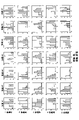
- FIG. 10 is a diagram showing the results of evaluation of a subject's smile according to an embodiment of the present invention
- FIG. 10 is a diagram showing the results of evaluation of a subject's smile according to an embodiment of the present invention
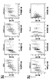
- FIG. 10 is a diagram showing results of evaluation of attractiveness of smiles of subjects according to one embodiment of the present invention.
- FIG. 10 is a diagram showing results of evaluation of attractiveness of smiles of subjects according to one embodiment of the present invention.
- FIG. 10 is a diagram showing results of evaluation of attractiveness of smiles of subjects according to one embodiment of the present invention.
- FIG. 2 is a diagram for explaining a myoelectric potential according to an embodiment of the present invention. It is a figure for demonstrating eight feature-values based on one Embodiment of this invention.
- the present invention can detect a smile using myoelectric potentials at multiple locations on the user's face.
- the multiple locations are two or more locations including at least one of the eye periphery and the zygomaticus minor muscle, the zygomaticus major muscle, and the laughter muscle.
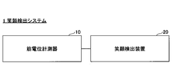
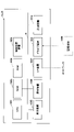
- FIG. 1 is an overall configuration diagram according to one embodiment of the present invention.
- smile detection system 1 includes myoelectric potential measuring device 10 and smile detection device 20 .
- the myoelectric potential measuring device 10 can transmit and receive data to and from the smile detecting device 20 via wired communication or wireless communication. Each of these will be described below.
- the myoelectric potential measuring instrument 10 is a device for measuring myoelectric potential. Based on the user's myoelectric potential measured by the myoelectric potential measuring device 10, the myoelectric potential measuring device 10 can determine whether or not the user is smiling, and output the determination result.
- the smile detection device 20 can determine whether or not the user is smiling based on the user's myoelectric potential measured by the myoelectric potential measuring device 10, and output the determination result.
- the smile detection device 20 may be any computer such as a personal computer, tablet terminal, or smart phone.
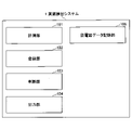
- FIG. 2 is a functional block diagram of the smile detection system 1 according to one embodiment of the present invention.
- smile detection system 1 can include measurement unit 101 , registration unit 102 , determination unit 103 , output unit 104 , and electromyogram data storage unit 105 .
- the smile detection system 1 can function as a measurement unit 101, a registration unit 102, a determination unit 103, and an output unit 104 by executing programs.
- the myoelectric potential measuring device 10 may include the measurement unit 101, the registration unit 102, the determination unit 103, the output unit 104, and the electromyogram data storage unit 105 (that is, the smile detection device 20 may not be used). ), the smile detection device 20 may include at least a part of the registration unit 102, the determination unit 103, the output unit 104, and the electromyogram data storage unit 105 (that is, the smile detection device 20 is used). .
- the measurement unit 101 measures the myoelectric potential of the user's face.
- the measurement unit 101 also generates an electromyogram (a record of action potentials generated in muscles over time).
- the measuring unit 101 measures myoelectric potentials in at least two of the orbicularis oculi muscle, the zygomaticus minor muscle, the zygomaticus major muscle, and the laughing muscle of the user's face.
- the measurement unit 101 measures the myoelectric potential (that is, 1 channel) at the right or left eye of the user's face, the right or left zygomaticus minor muscle, the right or left zygomaticus major muscle, and the right or left laughter muscle. A total of 2 channels of myoelectric potentials (that is, 1 channel) in one of .
- the measurement unit 101 measures myoelectric potentials (that is, two channels) in the left and right eyes of the user's face, and the muscle potentials in one of the left and right zygomatic muscles, the left and right zygomatic muscles, and the left and right laughing muscles. A total of 4 channels of potential (ie 2 channels) are measured.
- the myoelectric potential in the eye is the myoelectric potential in the orbicularis oculi muscle, the myoelectric potential in the frontalis muscle, and the like (hereinafter, the case of the orbicularis oculi muscle is described in this specification).
- the registration unit 102 causes the electromyogram data storage unit 105 to store the magnitude of the user's myoelectric potential (for example, the maximum value and minimum value (or amplitude)).
- the maximum and minimum values (or amplitude) of myoelectric potential when the user is smiling are registered, and the maximum and minimum values (or amplitude) of myoelectric potential are approximated. It is possible to determine whether or not the smile is attractive when the smile is obtained.
- the electromyogram data storage unit 105 stores information about myoelectric potential. ⁇ maximum value and minimum value (or amplitude) of myoelectric potential of the user>> and ⁇ characteristic amount of myoelectric potential of an attractive smile>> will be described below.
- the electromyogram data storage unit 105 stores the maximum value and minimum value (or amplitude) of the myoelectric potential of the user stored by the registration unit 102 .
- the electromyogram data storage unit 105 stores myoelectric potential characteristic values (e.g., integral value of myoelectric potential (smile size), rising speed, correlation between eyes and mouth) that are objectively judged to be an attractive smile. etc.) are stored.
- myoelectric potential characteristic values e.g., integral value of myoelectric potential (smile size), rising speed, correlation between eyes and mouth
- the determination unit 103 combines the feature amount of the myoelectric potential measured by the measurement unit 101 and the feature amount of the myoelectric potential (for example, it is determined whether or not the difference between the integral value of myoelectric potential (smile size, rising speed, correlation between eyes and mouth, etc.) is within a predetermined range.
- the determination unit 103 extracts a feature amount from the myoelectric potential measured by the measurement unit 101 . For example, the determination unit 103 determines the integrated values of myoelectric potentials at four locations on the user's face (indicating the size of a smile, as described later) and the smile stored in the electromyogram data storage unit 105. It is determined whether or not the difference between the size and is within a predetermined range. In addition, the determination unit 103 determines the speed at which the myoelectric potential at each of the four points on the user's face reaches its maximum value (indicating the rising speed, as described later), and the data stored in the electromyogram data storage unit 105. It is determined whether or not the difference between the current rising speed and the rising speed is within a predetermined range.
- the determining unit 103 mainly determines the correlation between the myoelectric potential of the orbicularis oculi muscle and the myoelectric potential of at least one of the zygomaticus minor muscle, the zygomaticus major muscle, and the laughing muscle (as will be described later, the myoelectric potential of the orbicularis oculi muscle). (indicating the correlation) and the strength of the correlation of the eye and opening stored in the electromyogram data storage unit 105 is within a predetermined range.
- the determination unit 103 may determine only the integral value of myoelectric potential (smile size), may determine only the rising speed, or may determine only the correlation between eyes and mouth.
- the determination unit 103 can determine whether the feature amount of myoelectric potential when the user is smiling is within a predetermined range for determining an attractive smile.
- the predetermined range may be a range determined based on the result of machine learning, or may be a range determined by a person.
- the output unit 104 outputs that the difference determined by the determination unit 103 is within or outside a predetermined range. Specifically, when the difference determined by the determination unit 103 is within or outside a predetermined range, the output unit 104 notifies the user by generating sound, vibration, light, a combination thereof, or the like. do. The output unit 104 immediately notifies the user based on the result of the judgment unit 103 .
- ⁇ Characteristic amount of myoelectric potential> the feature amount of the myoelectric potential that is objectively determined to be an attractive smile will be described.
- ⁇ integrated value of myoelectric potential (size of smile)>>, ⁇ rise speed>>, ⁇ correlation between eyes and mouth>>, and ⁇ others>> will be described below.
- the myoelectric potential characteristic quantity that is objectively determined to be an attractive smile is the integral value of the myoelectric potential.
- the feature amount is an integral value of myoelectric potentials at four locations (or two locations) on the user's face.
- the integral value of myoelectric potential indicates the size of a smile. By using smile size, smiles that are not large enough can be excluded from attractive smiles.
- the myoelectric potential feature quantity that is objectively judged to be an attractive smile is the speed at which the myoelectric potential reaches its maximum value. More specifically, the feature amount is the speed at which the myoelectric potential at each of four locations (or two locations) on the face reaches its maximum value. The speed at which the myoelectric potential at each of the four points on the face reaches its maximum value indicates the speed at which the person smiles the most.
- a smile with a slow rising speed that is, an unnatural smile with the slowest speed to smile
- the myoelectric potential characteristic quantity that is objectively judged to be an attractive smile is the strength of the correlation between the myoelectric potential around the eyes and the myoelectric potential around the mouth.
- the feature amount is mainly the strength of the correlation between the myoelectric potential of the orbicularis oculi muscle and the myoelectric potential of at least one of the zygomaticus minor muscle, the zygomaticus major muscle, and the laughing muscle.
- the strength of the correlation between the myoelectric potential mainly in the orbicularis oculi muscle and the myoelectric potential in at least one of the zygomaticus minor muscle, the zygomaticus major muscle, and the laughing muscle is related to eye movement and mouth movement when smiling.
- the feature values of myoelectric potential that are objectively judged to be an attractive smile are the magnitude of myoelectric potential, the timing at which myoelectric potential was measured, the pattern of change over time in myoelectric potential, and the rate of fall. (In other words, it may be information about the speed at which myoelectric potentials at four points on the face return from a smiling state to a straight face state).
- the feature amount of myoelectric potential that is objectively judged to be an attractive smile is a combination of a plurality of types of feature amounts of myoelectric potential, may be the average, deviation, or the like.
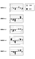
- FIG. 5 is a diagram showing the results of evaluating the attractiveness of smiles of subjects according to one embodiment of the present invention.
- Each smile (smile #1, smile #2, smile #2, smile #1, smile #2, 7 types of smiles (smile #3, smile #4, smile #5, smile #6, smile #7) are shown.
- the horizontal axis indicates attractiveness (that is, the degree of attractiveness and the degree of unattractiveness (standardized based on the standard deviation)), and the vertical axis indicates the number of evaluators who evaluated the attractiveness. indicates
- the evaluation of the attractiveness of a smile varies depending on the evaluator. Therefore, in one embodiment of the present invention, as shown in FIG.
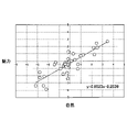
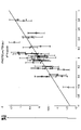
- the degree of attractiveness of a smile can be evaluated with an accuracy of approximately 89%, taking into account variations among evaluators.
- 25%, 50%, and 75% indicate the top 25%, 50% (median), and 75% levels of scores by 40 evaluators.
- the accuracy is determined as the "correct answer" when the estimated value is within 25 to 75 percent.
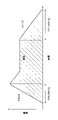
- FIG. 7 is a diagram for explaining the myoelectric potential according to one embodiment of the present invention.
- an integral electromyogram as shown in FIG. 7 can be used as the feature quantity of the myoelectric potential.
- the attack time is the period until the myoelectric potential at each of the four points on the face reaches its maximum value.
- the release time is the period until the myoelectric potentials at four points on the face return from the smiling state to the straight face state.
- FIG. 8 is a diagram for explaining eight feature amounts according to one embodiment of the present invention.
- Myopotentials mainly in the left and right orbicularis oculi muscles of the face i.e., 2 channels
- myopotentials in one of the left and right zygomatic muscles, the left and right zygomatic muscles, and the left and right laughing muscles i.e., 2 channels). channel
- the iEMG is the integrated value of myoelectric potentials (that is, the size of a smile) at each of four points on the face (that is, each channel of 4 channels).
- iEMG is the area of the hatched portion in FIG.
- iEMG(min) indicates the minimum integral value of myoelectric potential in each channel.
- iEMG(ave) indicates the average of the integral values of myoelectric potential in each channel among the four channels.
- iEMG(dev) indicates the variance of the integral value of myoelectric potential in each channel among the four channels.
- iEMG(w1) is the weighted value of the second half of the measured time.
- iEMG(w2) is the weighted first half of the measurement time.
- B(ave) indicates the speed at which the myoelectric potential at each of the four points on the face (that is, each of the four channels) reaches its maximum value (that is, the speed at which the person smiles the most). More specifically, it is the average of the velocities of the four channels until the myoelectric potential reaches the maximum value in each channel.
- B(dev) is mainly the strength of the correlation between the myoelectric potential in the orbicularis oculi muscle and the myoelectric potential in at least one of the zygomaticus minor muscle, the zygomaticus major muscle, and the laughing muscle (that is, when smiling strength of correlation between eye movements and mouth movements). More specifically, it is the variance of the velocities among the four channels until the myoelectric potential in each channel reaches its maximum value. It can be interpreted that a small variance indicates a strong correlation, and a large variance indicates a weak correlation.
- FIG. 9 is a diagram for explaining the relationship between the attractiveness of a smile and the correlation between smile size, rising speed, and eye opening according to an embodiment of the present invention. As shown in FIG. 9, the degree of attractiveness of a smile correlated with the size of the smile (iEMG), the rising speed (B(ave)), and the correlation between the eye and mouth (B(dev)).
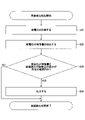
- FIG. 10 is a flow chart of registration processing according to an embodiment of the present invention.
- step 11 (S11) the measurement unit 101 measures the myoelectric potential of the user's face when the user is smiling (for example, when the user expresses the most attractive smile among his or her own smiles). do.
- the measurement unit 101 measures myoelectric potentials mainly in the orbicularis oculi muscles on the left and right sides of the user's face (that is, two channels), Myopotentials in one (ie two channels) are measured.
- the registration unit 102 causes the electromyogram data storage unit 105 to store the magnitude of the user's myoelectric potential (for example, the maximum value and minimum value (or amplitude)).
- FIG. 11 is a flowchart of smile detection processing according to an embodiment of the present invention.
- the measurement unit 101 measures the myoelectric potential of the user's face.
- the measurement unit 101 measures myoelectric potentials mainly in the orbicularis oculi muscles on the left and right sides of the user's face (that is, two channels), Myopotentials in one (ie two channels) are measured.
- the determination unit 103 extracts the feature amount of the myoelectric potential of S21.
- step 23 the determination unit 103 determines the difference between the myoelectric potential feature amount extracted in S22 and the registered feature amount (that is, the feature amount stored in the electromyogram data storage unit 105). It is determined whether the difference is within a predetermined range. If it is within the predetermined range, go to step 24 . If it is not within the predetermined range, the process is terminated (it may be output that it is not within the predetermined range).
- step 24 (S24) the output unit 104 outputs that the difference in S23 is within a predetermined range.
- the myoelectric potential measuring device 10 can be used to support the expression of an attractive smile. Specifically, the myoelectric potential measuring device 10 is caused to measure the myoelectric potential of the user's face, and the user can be notified that the user has an attractive smile according to the output of the myoelectric potential measuring device 10. .
- the user is notified in real time at the moment when the user has an attractive smile, so that the user can be notified of "what kind of feeling” or "what kind of feeling”. It is possible for the user to notice whether or not the user has become able to smile.
- the user's brain associates and remembers the "things” and “moments” that made him/herself have an attractive smile, so that the user can naturally have an attractive smile.
- FIG. 12 is a block diagram showing an example of the hardware configuration of the myoelectric potential measuring device 10 and the smile detection device 20 according to one embodiment of the present invention.
- the myoelectric potential measuring instrument 10 has a measuring device 1010 that measures myoelectric potential.
- the myoelectric potential measuring device 10 and the smile detection device 20 have a CPU (Central Processing Unit) 1001, a ROM (Read Only Memory) 1002, and a RAM (Random Access Memory) 1003.
- the CPU 1001, ROM 1002, and RAM 1003 form a so-called computer.
- the myoelectric potential measuring device 10 and the smile detection device 20 can have an auxiliary storage device 1004, a display device 1005, an operation device 1006, an I/F (Interface) device 1007, and a drive device 1008.
- the hardware of the myoelectric potential measuring device 10 and the smile detection device 20 are connected to each other via a bus B.
- the CPU 1001 is an arithmetic device that executes various programs installed in the auxiliary storage device 1004 .
- the ROM 1002 is a non-volatile memory.
- the ROM 1002 functions as a main storage device that stores various programs, data, etc. necessary for the CPU 1001 to execute various programs installed in the auxiliary storage device 1004 .
- the ROM 1002 functions as a main storage device that stores boot programs such as BIOS (Basic Input/Output System) and EFI (Extensible Firmware Interface).
- BIOS Basic Input/Output System
- EFI Extensible Firmware Interface
- the RAM 1003 is a volatile memory such as DRAM (Dynamic Random Access Memory) or SRAM (Static Random Access Memory).
- the RAM 1003 functions as a main storage device that provides a work area that is developed when various programs installed in the auxiliary storage device 1004 are executed by the CPU 1001 .
- the auxiliary storage device 1004 is an auxiliary storage device that stores various programs and information used when various programs are executed.
- the display device 1005 is a display device that displays the internal state of the myoelectric potential measuring instrument 10 and the smile detection device 20, and the like.
- the operation device 1006 is an input device for inputting various instructions to the myoelectric potential measuring device 10 and the smile detecting device 20 by the administrator of the myoelectric potential measuring device 10 and the smile detecting device 20 .
- the I/F device 1007 is a communication device for connecting to a network and communicating with the myoelectric potential measuring device 10 and the smile detection device 20.
- a drive device 1008 is a device for setting a storage medium 1009 .
- the storage medium 1009 here includes media such as CD-ROMs, flexible disks, magneto-optical disks, etc., which record information optically, electrically or magnetically.
- the storage medium 1009 may also include a semiconductor memory that electrically records information such as an EPROM (Erasable Programmable Read Only Memory), a flash memory, or the like.
- auxiliary storage device 1004 Various programs to be installed in the auxiliary storage device 1004 are installed by, for example, setting the distributed storage medium 1009 in the drive device 1008 and reading the various programs recorded in the storage medium 1009 by the drive device 1008. be done. Alternatively, various programs installed in the auxiliary storage device 1004 may be installed by being downloaded from the network via the I/F device 1007 .
Landscapes
- Health & Medical Sciences (AREA)
- Life Sciences & Earth Sciences (AREA)
- Engineering & Computer Science (AREA)
- Surgery (AREA)
- General Health & Medical Sciences (AREA)
- Biophysics (AREA)
- Biomedical Technology (AREA)
- Heart & Thoracic Surgery (AREA)
- Medical Informatics (AREA)
- Molecular Biology (AREA)
- Physics & Mathematics (AREA)
- Animal Behavior & Ethology (AREA)
- Pathology (AREA)
- Public Health (AREA)
- Veterinary Medicine (AREA)
- Child & Adolescent Psychology (AREA)
- Developmental Disabilities (AREA)
- Educational Technology (AREA)
- Hospice & Palliative Care (AREA)
- Psychiatry (AREA)
- Psychology (AREA)
- Social Psychology (AREA)
- Measurement And Recording Of Electrical Phenomena And Electrical Characteristics Of The Living Body (AREA)
Abstract
Description
図1は、本発明の一実施形態に係る全体の構成図である。図1に示されるように、笑顔検出システム1は、筋電位計測器10および笑顔検出装置20を含む。筋電位計測器10は、有線通信または無線通信を介して、笑顔検出装置20とデータを送受信することができる。以下、それぞれについて説明する。
図2は、本発明の一実施形態に係る笑顔検出システム1の機能ブロック図である。図2に示されるように、笑顔検出システム1は、計測部101と、登録部102と、判断部103と、出力部104と、筋電図データ記憶部105と、を備えることができる。また、笑顔検出システム1は、プログラムを実行することで、計測部101、登録部102、判断部103、出力部104として機能することができる。
筋電図データ記憶部105には、登録部102が記憶させたユーザの筋電位の最大値および最小値(または振れ幅)が記憶されている。
筋電図データ記憶部105には、魅力的な笑顔であると客観的に判断される筋電位の特徴量(例えば、筋電位の積分値(笑顔の大きさ)、立ち上がり速度、目口の相関等)が記憶されている。
所定の範囲は、機械学習の結果に基づいて決められた範囲であってもよいし、あるいは、人が決めた範囲であってもよい。
ここで、魅力的な笑顔であると客観的に判断される筋電位の特徴量について説明する。以下、<<筋電位の積分値(笑顔の大きさ)>>、<<立ち上がり速度>>、<<目口の相関>>、<<その他>>に分けて説明する。
例えば、魅力的な笑顔であると客観的に判断される筋電位の特徴量は、筋電位の積分値である。より具体的には、特徴量は、ユーザの顔の4箇所(なお、2箇所でもよい)の各所における筋電位の積分値である。筋電位の積分値は、笑顔の大きさを示す。笑顔の大きさを用いることにより、十分な大きさではない笑顔を、魅力的な笑顔から除外することができる。
例えば、魅力的な笑顔であると客観的に判断される筋電位の特徴量は、筋電位が最大値になるまでの速度である。より具体的には、特徴量は、顔の4箇所(なお、2箇所でもよい)の各所における筋電位が最大値になるまでの速度である。顔の4箇所の各所における筋電位が最大値になるまでの速度は、最も笑顔になるまでの速度を示す。立ち上がり速度を用いることにより、立ち上がり速度が遅い笑顔(すなわち、最も笑顔になるまでの速度が遅い不自然な笑顔)を、魅力的な笑顔から除外することができる。
例えば、魅力的な笑顔であると客観的に判断される筋電位の特徴量は、目周辺における筋電位と口周辺における筋電位との相関の強さである。より具体的には、特徴量は、主に眼輪筋における筋電位と、小頬骨筋と大頬骨筋と笑筋とのうちの少なくとも1つにおける筋電位と、の相関の強さである。主に眼輪筋における筋電位と、小頬骨筋と大頬骨筋と笑筋とのうちの少なくとも1つにおける筋電位と、の相関の強さは、笑顔であるときの目の動きと口の動きとの相関の強さを示す。目口の相関を用いることにより、目口の相関の強さが弱い笑顔(すなわち、目口が相関していない(例えば、目が動いていない)不自然な笑顔)を、魅力的な笑顔から除外することができる。
例えば、魅力的な笑顔であると客観的に判断される筋電位の特徴量は、筋電位の大きさ、筋電位が計測されたタイミング、筋電位の経時的な変化のパターン、立ち下がりの速度(つまり、顔の4箇所の各所における筋電位が、笑顔の状態から真顔の状態に戻るまでの速度の情報)であってもよい。また、魅力的な笑顔であると客観的に判断される筋電位の特徴量は、複数の種類の筋電位の特徴量の組み合わせ、筋電位の特徴量の4チャンネル(顔の4か所)間の平均、偏差等であってもよい。
以下、図10を参照しながら登録処理について説明し、図11を参照しながら笑顔検出処理について説明する。
図10は、本発明の一実施形態に係る登録処理のフローチャートである。
図11は、本発明の一実施形態に係る笑顔検出処理のフローチャートである。
このように、本発明の一実施形態では、ユーザが魅力的な笑顔になった瞬間にリアルタイムにユーザにその旨が知らされるので、「どんな感覚だった時に」あるいは「どんな気持ちの時に」その笑顔になれたのかをユーザが気付くことができる。自分が魅力的な笑顔になれた「こと」や「瞬間」がどういうもの・時なのかを脳が関連付けて覚えていくことで、ユーザは、自然と魅力的な笑顔になれるようになる。
図12は、本発明の一実施形態に係る筋電位計測器10および笑顔検出装置20のハードウェア構成の一例を示すブロック図である。
10 筋電位計測器
20 笑顔検出装置
101 計測部
102 登録部
103 判断部
104 出力部
105 筋電図データ記憶部
1001 CPU
1002 ROM
1003 RAM
1004 補助記憶装置
1005 表示装置
1006 操作装置
1007 I/F装置
1008 ドライブ装置
1009 記憶媒体
1010 計測装置
Claims (12)
- 筋電位を計測する筋電位計測器であって、
前記筋電位計測器が計測した筋電位の特徴量と、魅力的な笑顔であると客観的に判断される筋電位の特徴量と、の差分が所定の範囲内であるか否かを判断する判断部と、
前記差分が所定の範囲内または範囲外であることを出力する出力部と
を備えた、筋電位計測器。 - 前記筋電位の特徴量は、筋電位の大きさ、筋電位の経時的な変化のパターン、立ち下がりの速度、複数の種類の該情報の組み合わせ、該情報のユーザの顔の複数箇所間の平均および偏差の情報をさらに含む、請求項1に記載の筋電位計測器。
- 前記筋電位の特徴量は、ユーザの顔の複数箇所の各所における筋電位の積分値である、請求項1に記載の筋電位計測器。
- 前記筋電位の特徴量は、ユーザの顔の複数箇所の各所における筋電位が最大値になるまでの速度である、請求項1に記載の筋電位計測器。
- 前記筋電位の特徴量は、目周辺における筋電位と、小頬骨筋と大頬骨筋と笑筋とのうちの少なくとも1つにおける筋電位と、の相関の強さである、請求項1に記載の筋電位計測器。
- 前記出力部は、前記判断部の結果に基づいて、即時的にユーザに通知する、請求項1から5のいずれか一項に記載の筋電位計測器。
- 前記出力部は、音、振動、光、それらの組み合わせを生じさせることによってユーザに通知する、請求項1から6のいずれか一項に記載の筋電位計測器。
- 前記所定の範囲は、機械学習の結果に基づいて決められた範囲である、請求項1から7のいずれか一項に記載の筋電位計測器。
- 前記複数箇所は、眼周辺、および、小頬骨筋と大頬骨筋と笑筋とのうちの少なくとも1つを含む2箇所以上である、請求項2から4のいずれか一項に記載の筋電位計測器。
- 筋電位を計測する筋電位計測器が実行する方法であって、
前記筋電位計測器が計測した筋電位の特徴量と、魅力的な笑顔であると客観的に判断される筋電位の特徴量と、の差分が所定の範囲内であるか否かを判断するステップと、
前記差分が所定の範囲内または範囲外であることを出力するステップと
を含む、方法。 - 筋電位を計測する筋電位計測器と、コンピュータと、を含むシステムであって、
前記筋電位計測器が計測した筋電位の特徴量と、魅力的な笑顔であると客観的に判断される筋電位の特徴量と、の差分が所定の範囲内であるか否かを判断する判断部と、
前記差分が所定の範囲内または範囲外であることを出力する出力部と
を備えた、システム。 - 筋電位を計測する筋電位計測器を用いて魅力的な笑顔の表出を支援する方法であって、
前記筋電位計測器は、
前記筋電位計測器が計測した筋電位の特徴量と、魅力的な笑顔であると客観的に判断される筋電位の特徴量と、の差分が所定の範囲内であるか否かを判断する判断部と、
前記差分が所定の範囲内または範囲外であることを出力する出力部と
を備え、
前記筋電位計測器に、ユーザの顔の筋電位を計測させるステップと、
前記筋電位計測器の出力に応じて、前記ユーザが魅力的な笑顔であることを前記ユーザに通知するステップと
を含む方法。
Priority Applications (2)
| Application Number | Priority Date | Filing Date | Title |
|---|---|---|---|
| JP2023506985A JP7803015B2 (ja) | 2021-03-17 | 2022-03-07 | 筋電位計測器、方法、およびシステム |
| CN202280015517.0A CN116887754B (zh) | 2021-03-17 | 2022-03-07 | 肌电位计测器、方法及系统 |
Applications Claiming Priority (2)
| Application Number | Priority Date | Filing Date | Title |
|---|---|---|---|
| JP2021043016 | 2021-03-17 | ||
| JP2021-043016 | 2021-03-17 |
Publications (1)
| Publication Number | Publication Date |
|---|---|
| WO2022196419A1 true WO2022196419A1 (ja) | 2022-09-22 |
Family
ID=83320454
Family Applications (1)
| Application Number | Title | Priority Date | Filing Date |
|---|---|---|---|
| PCT/JP2022/009796 Ceased WO2022196419A1 (ja) | 2021-03-17 | 2022-03-07 | 筋電位計測器、方法、およびシステム |
Country Status (2)
| Country | Link |
|---|---|
| JP (1) | JP7803015B2 (ja) |
| WO (1) | WO2022196419A1 (ja) |
Cited By (1)
| Publication number | Priority date | Publication date | Assignee | Title |
|---|---|---|---|---|
| JP7477000B1 (ja) | 2023-02-22 | 2024-05-01 | Smk株式会社 | 筋活動解析装置、筋活動解析方法及び筋活動解析プログラム |
Citations (2)
| Publication number | Priority date | Publication date | Assignee | Title |
|---|---|---|---|---|
| JP2011143059A (ja) * | 2010-01-14 | 2011-07-28 | Univ Of Tsukuba | 顔面動作推定装置及び顔面動作推定方法 |
| JP2017021737A (ja) * | 2015-07-15 | 2017-01-26 | Kddi株式会社 | 筋電信号を用いてアプリケーションに感情識別子を付与するプログラム、端末及びシステム |
-
2022
- 2022-03-07 WO PCT/JP2022/009796 patent/WO2022196419A1/ja not_active Ceased
- 2022-03-07 JP JP2023506985A patent/JP7803015B2/ja active Active
Patent Citations (2)
| Publication number | Priority date | Publication date | Assignee | Title |
|---|---|---|---|---|
| JP2011143059A (ja) * | 2010-01-14 | 2011-07-28 | Univ Of Tsukuba | 顔面動作推定装置及び顔面動作推定方法 |
| JP2017021737A (ja) * | 2015-07-15 | 2017-01-26 | Kddi株式会社 | 筋電信号を用いてアプリケーションに感情識別子を付与するプログラム、端末及びシステム |
Non-Patent Citations (1)
| Title |
|---|
| TORU SUGAHARA: "Analysis of Shape and Facial Muscle Activity of Smiles ", vol. 34, no. 133, 1 April 2014 (2014-04-01), pages 14 - 19, XP055968438 * |
Cited By (2)
| Publication number | Priority date | Publication date | Assignee | Title |
|---|---|---|---|---|
| JP7477000B1 (ja) | 2023-02-22 | 2024-05-01 | Smk株式会社 | 筋活動解析装置、筋活動解析方法及び筋活動解析プログラム |
| WO2024176648A1 (ja) * | 2023-02-22 | 2024-08-29 | Smk株式会社 | 筋活動解析装置、筋活動解析方法及び筋活動解析プログラム |
Also Published As
| Publication number | Publication date |
|---|---|
| JPWO2022196419A1 (ja) | 2022-09-22 |
| JP7803015B2 (ja) | 2026-01-21 |
| CN116887754A (zh) | 2023-10-13 |
Similar Documents
| Publication | Publication Date | Title |
|---|---|---|
| US20180060757A1 (en) | Data annotation method and apparatus for enhanced machine learning | |
| JP6755839B2 (ja) | 運動パフォーマンス推定装置、その方法、およびプログラム | |
| JP7278972B2 (ja) | 表情解析技術を用いた商品に対するモニタの反応を評価するための情報処理装置、情報処理システム、情報処理方法、及び、プログラム | |
| JP7501275B2 (ja) | 情報処理装置、情報処理方法、およびプログラム | |
| US12543983B2 (en) | Systems and methods for emotion prediction | |
| US20080043025A1 (en) | Using DISC to Evaluate The Emotional Response Of An Individual | |
| CN117179767A (zh) | 基于患者面部频域特征的抑郁辅助评估的方法及设备 | |
| JP6479708B2 (ja) | 特徴量抽出装置、推定装置、それらの方法、およびプログラム | |
| JP7803015B2 (ja) | 筋電位計測器、方法、およびシステム | |
| Kaur et al. | Digital eye strain detection system based on svm | |
| US20200074240A1 (en) | Method and Apparatus for Improving Limited Sensor Estimates Using Rich Sensors | |
| CN106649594B (zh) | 数据的展示方法和装置 | |
| JP2024172693A (ja) | 幸福度の推定方法、幸福度の推定プログラム、幸福度の推定装置およびモデルの生成方法 | |
| EP4060617A1 (en) | Image processing system and method | |
| CN118315052A (zh) | 一种基于多模态的智能交互ad筛查系统、装置 | |
| Carcellar et al. | Self-Applicable Eye Strain Detection Through the Measurement of Blink Rate Using Raspberry Pi | |
| WO2024040251A2 (en) | Multimodal automated acute stroke detection | |
| JP7697518B2 (ja) | 評価方法、評価システム、およびプログラム | |
| WO2023189309A1 (ja) | コンピュータプログラム、情報処理方法及び情報処理装置 | |
| WO2024004210A1 (ja) | 情報処理プログラム、情報処理方法、および情報処理装置 | |
| Ferrato et al. | Multimodal Physiological Sensing for Adaptive Learning Environments | |
| JP7773902B2 (ja) | 情報処理方法、情報処理装置、および制御プログラム | |
| JP7537207B2 (ja) | 情報処理装置、情報処理方法、およびプログラム | |
| JP7501276B2 (ja) | 情報処理装置、情報処理方法、およびプログラム | |
| JP7537208B2 (ja) | 情報処理装置、情報処理方法、およびプログラム |
Legal Events
| Date | Code | Title | Description |
|---|---|---|---|
| 121 | Ep: the epo has been informed by wipo that ep was designated in this application |
Ref document number: 22771172 Country of ref document: EP Kind code of ref document: A1 |
|
| WWE | Wipo information: entry into national phase |
Ref document number: 202280015517.0 Country of ref document: CN Ref document number: 2023506985 Country of ref document: JP |
|
| NENP | Non-entry into the national phase |
Ref country code: DE |
|
| 122 | Ep: pct application non-entry in european phase |
Ref document number: 22771172 Country of ref document: EP Kind code of ref document: A1 |