WO2022190846A1 - 医用画像処理装置、医用画像処理方法、医用画像処理プログラム、および放射線治療装置 - Google Patents
医用画像処理装置、医用画像処理方法、医用画像処理プログラム、および放射線治療装置 Download PDFInfo
- Publication number
- WO2022190846A1 WO2022190846A1 PCT/JP2022/007094 JP2022007094W WO2022190846A1 WO 2022190846 A1 WO2022190846 A1 WO 2022190846A1 JP 2022007094 W JP2022007094 W JP 2022007094W WO 2022190846 A1 WO2022190846 A1 WO 2022190846A1
- Authority
- WO
- WIPO (PCT)
- Prior art keywords
- image
- tracking
- unit
- patient
- likelihood distribution
- Prior art date
- Legal status (The legal status is an assumption and is not a legal conclusion. Google has not performed a legal analysis and makes no representation as to the accuracy of the status listed.)
- Ceased
Links
Images





Classifications
-
- A—HUMAN NECESSITIES
- A61—MEDICAL OR VETERINARY SCIENCE; HYGIENE
- A61N—ELECTROTHERAPY; MAGNETOTHERAPY; RADIATION THERAPY; ULTRASOUND THERAPY
- A61N5/00—Radiation therapy
- A61N5/10—X-ray therapy; Gamma-ray therapy; Particle-irradiation therapy
- A61N5/1048—Monitoring, verifying, controlling systems and methods
- A61N5/1049—Monitoring, verifying, controlling systems and methods for verifying the position of the patient with respect to the radiation beam
-
- A—HUMAN NECESSITIES
- A61—MEDICAL OR VETERINARY SCIENCE; HYGIENE
- A61B—DIAGNOSIS; SURGERY; IDENTIFICATION
- A61B90/00—Instruments, implements or accessories specially adapted for surgery or diagnosis and not covered by any of the groups A61B1/00 - A61B50/00, e.g. for luxation treatment or for protecting wound edges
- A61B90/39—Markers, e.g. radio-opaque or breast lesions markers
-
- A—HUMAN NECESSITIES
- A61—MEDICAL OR VETERINARY SCIENCE; HYGIENE
- A61N—ELECTROTHERAPY; MAGNETOTHERAPY; RADIATION THERAPY; ULTRASOUND THERAPY
- A61N5/00—Radiation therapy
- A61N5/10—X-ray therapy; Gamma-ray therapy; Particle-irradiation therapy
- A61N5/103—Treatment planning systems
- A61N5/1037—Treatment planning systems taking into account the movement of the target, e.g. 4D-image based planning
-
- A—HUMAN NECESSITIES
- A61—MEDICAL OR VETERINARY SCIENCE; HYGIENE
- A61N—ELECTROTHERAPY; MAGNETOTHERAPY; RADIATION THERAPY; ULTRASOUND THERAPY
- A61N5/00—Radiation therapy
- A61N5/10—X-ray therapy; Gamma-ray therapy; Particle-irradiation therapy
- A61N5/103—Treatment planning systems
- A61N5/1039—Treatment planning systems using functional images, e.g. PET or MRI
-
- A—HUMAN NECESSITIES
- A61—MEDICAL OR VETERINARY SCIENCE; HYGIENE
- A61N—ELECTROTHERAPY; MAGNETOTHERAPY; RADIATION THERAPY; ULTRASOUND THERAPY
- A61N5/00—Radiation therapy
- A61N5/10—X-ray therapy; Gamma-ray therapy; Particle-irradiation therapy
- A61N5/1048—Monitoring, verifying, controlling systems and methods
- A61N5/1064—Monitoring, verifying, controlling systems and methods for adjusting radiation treatment in response to monitoring
- A61N5/1065—Beam adjustment
- A61N5/1067—Beam adjustment in real time, i.e. during treatment
-
- G—PHYSICS
- G06—COMPUTING OR CALCULATING; COUNTING
- G06T—IMAGE DATA PROCESSING OR GENERATION, IN GENERAL
- G06T7/00—Image analysis
- G06T7/20—Analysis of motion
- G06T7/246—Analysis of motion using feature-based methods, e.g. the tracking of corners or segments
-
- G—PHYSICS
- G06—COMPUTING OR CALCULATING; COUNTING
- G06T—IMAGE DATA PROCESSING OR GENERATION, IN GENERAL
- G06T7/00—Image analysis
- G06T7/20—Analysis of motion
- G06T7/246—Analysis of motion using feature-based methods, e.g. the tracking of corners or segments
- G06T7/248—Analysis of motion using feature-based methods, e.g. the tracking of corners or segments involving reference images or patches
-
- A—HUMAN NECESSITIES
- A61—MEDICAL OR VETERINARY SCIENCE; HYGIENE
- A61B—DIAGNOSIS; SURGERY; IDENTIFICATION
- A61B90/00—Instruments, implements or accessories specially adapted for surgery or diagnosis and not covered by any of the groups A61B1/00 - A61B50/00, e.g. for luxation treatment or for protecting wound edges
- A61B90/39—Markers, e.g. radio-opaque or breast lesions markers
- A61B2090/3966—Radiopaque markers visible in an X-ray image
-
- A—HUMAN NECESSITIES
- A61—MEDICAL OR VETERINARY SCIENCE; HYGIENE
- A61N—ELECTROTHERAPY; MAGNETOTHERAPY; RADIATION THERAPY; ULTRASOUND THERAPY
- A61N5/00—Radiation therapy
- A61N5/10—X-ray therapy; Gamma-ray therapy; Particle-irradiation therapy
- A61N5/1048—Monitoring, verifying, controlling systems and methods
- A61N5/1049—Monitoring, verifying, controlling systems and methods for verifying the position of the patient with respect to the radiation beam
- A61N2005/1061—Monitoring, verifying, controlling systems and methods for verifying the position of the patient with respect to the radiation beam using an x-ray imaging system having a separate imaging source
-
- A—HUMAN NECESSITIES
- A61—MEDICAL OR VETERINARY SCIENCE; HYGIENE
- A61N—ELECTROTHERAPY; MAGNETOTHERAPY; RADIATION THERAPY; ULTRASOUND THERAPY
- A61N5/00—Radiation therapy
- A61N5/10—X-ray therapy; Gamma-ray therapy; Particle-irradiation therapy
- A61N5/1048—Monitoring, verifying, controlling systems and methods
- A61N5/1049—Monitoring, verifying, controlling systems and methods for verifying the position of the patient with respect to the radiation beam
- A61N2005/1061—Monitoring, verifying, controlling systems and methods for verifying the position of the patient with respect to the radiation beam using an x-ray imaging system having a separate imaging source
- A61N2005/1062—Monitoring, verifying, controlling systems and methods for verifying the position of the patient with respect to the radiation beam using an x-ray imaging system having a separate imaging source using virtual X-ray images, e.g. digitally reconstructed radiographs [DRR]
-
- G—PHYSICS
- G06—COMPUTING OR CALCULATING; COUNTING
- G06T—IMAGE DATA PROCESSING OR GENERATION, IN GENERAL
- G06T2207/00—Indexing scheme for image analysis or image enhancement
- G06T2207/10—Image acquisition modality
- G06T2207/10116—X-ray image
-
- G—PHYSICS
- G06—COMPUTING OR CALCULATING; COUNTING
- G06T—IMAGE DATA PROCESSING OR GENERATION, IN GENERAL
- G06T2207/00—Indexing scheme for image analysis or image enhancement
- G06T2207/10—Image acquisition modality
- G06T2207/10116—X-ray image
- G06T2207/10121—Fluoroscopy
-
- G—PHYSICS
- G06—COMPUTING OR CALCULATING; COUNTING
- G06T—IMAGE DATA PROCESSING OR GENERATION, IN GENERAL
- G06T2207/00—Indexing scheme for image analysis or image enhancement
- G06T2207/20—Special algorithmic details
- G06T2207/20076—Probabilistic image processing
-
- G—PHYSICS
- G06—COMPUTING OR CALCULATING; COUNTING
- G06T—IMAGE DATA PROCESSING OR GENERATION, IN GENERAL
- G06T2207/00—Indexing scheme for image analysis or image enhancement
- G06T2207/30—Subject of image; Context of image processing
- G06T2207/30204—Marker
Definitions
- Embodiments of the present invention relate to a medical image processing apparatus, a medical image processing method, a medical image processing program, and a radiotherapy apparatus.
- Radiation therapy is a treatment method that destroys lesions in the patient's body by irradiating them with radiation.
- the radiation must be applied accurately to the position of the lesion. This is because if normal tissues in the patient's body are irradiated with radiation, the normal tissues may also be affected.
- CT computed tomography
- the position of the lesion in the patient's body is three-dimensionally grasped.
- the irradiation direction and the intensity of the radiation to be irradiated are planned so as to reduce irradiation to normal tissues.
- the position of the patient is adjusted to the position of the patient in the treatment planning stage, and the lesion is irradiated with radiation according to the irradiation direction and irradiation intensity planned in the treatment planning stage.
- the 3D CT data is virtually arranged in the treatment room, and the position of the patient actually laid on the movable bed in the treatment room matches the position of the 3D CT data.
- Adjust the position of the bed so that More specifically, it is a digital reconstruction that virtually reconstructs the X-ray fluoroscopic image from the X-ray fluoroscopic image of the patient's body taken while the patient is lying on a bed and the three-dimensional CT image taken at the time of treatment planning.
- DRR Digitally Reconstructed Radiograph
- the location of the lesion can be tracked. If the lesion is not clearly visible in the fluoroscopic image, the location of the lesion can be tracked indirectly by tracking markers placed inside the patient.
- irradiating radiation there are tracking irradiation in which the position of the lesion is tracked and irradiated, and ambush irradiation in which irradiation is performed when the lesion reaches the position at the time of treatment planning. These irradiation methods are called respiratory-gated irradiation methods.
- an object such as a lesion or marker overlaps an organ such as the liver that has a low X-ray transmittance, the lesion or marker may not appear clearly in the X-ray fluoroscopic image.
- the problem to be solved by the present invention is to provide a medical image processing apparatus, a medical image processing method, a medical image processing program, and a radiotherapy apparatus capable of highly accurately tracking an object inside a patient's body from a fluoroscopic image of the patient. It is to be.
- a medical image processing apparatus is an apparatus that tracks the position of an object inside a patient's body, and includes a first image acquisition unit, a second image acquisition unit, a first likelihood distribution calculation unit, and a tracking availability determination unit. and a tracking unit.
- the first image acquiring unit acquires a plurality of first images, which are fluoroscopic images of the patient, taken in different imaging directions.
- the second image acquisition unit acquires a plurality of second images, which are fluoroscopic images of the patient generated at different times from the first image and taken in different imaging directions.
- the first likelihood distribution calculation unit calculates a first likelihood distribution indicating a distribution of likelihoods representing the object-likeness in each of the plurality of first images acquired by the first image acquisition unit.
- the tracking propriety determining unit determines whether the object can be tracked based on the first likelihood distribution calculated by the first likelihood distribution calculating unit.
- the tracking unit tracks the position of the object in the second image acquired by the second image acquisition unit according to the determination result of the tracking availability determination unit.
- FIG. 1 is a block diagram showing a schematic configuration of a treatment system according to a first embodiment
- FIG. 1 is a block diagram showing a schematic configuration of a medical image processing apparatus according to a first embodiment
- FIG. 4 is a diagram showing an example of a first image according to the first embodiment
- FIG. 5 is a diagram showing an example of a template used for calculating the degree of separation according to the first embodiment
- 4 is a flow chart showing the operation of the medical image processing apparatus in the pre-treatment stage of the patient according to the first embodiment
- 4 is a flowchart showing the operation of the medical image processing apparatus during treatment of a patient according to the first embodiment
- FIG. 2 is a block diagram showing a schematic configuration of a medical image processing apparatus according to a second embodiment
- FIG. 9 is a flow chart showing the operation of the medical image processing apparatus in the pre-treatment stage of the patient according to the second embodiment
- FIG. 11 is a block diagram showing a schematic configuration of a radiotherapy apparatus according to a third embodiment
- 9 is a flow chart showing the operation of the radiotherapy apparatus during treatment of a patient according to the third embodiment
- a medical image processing apparatus, a medical image processing method, a medical image processing program, and a radiotherapy apparatus will be described below with reference to the drawings.
- FIG. 1 is a block diagram showing a schematic configuration of a treatment system according to the first embodiment.
- the treatment system 1 includes, for example, a treatment table 10, a bed control unit 11, two radiation sources 20 (radiation source 20-1 and radiation source 20-2), and two radiation detectors 30 (radiation detector 30- 1 and radiation detector 30 - 2 ), a therapeutic beam irradiation gate 40 , an irradiation control device 50 , and a medical image processing device 100 .
- the "-" and the number following each symbol shown in FIG. 1 are for identifying the correspondence. More specifically, the correspondence relationship between the radiation source 20 and the radiation detector 30 indicates that the radiation source 20-1 and the radiation detector 30-1 form one set. 20-2 and the radiation detector 30-2 correspond to each other and form another set. In the following description, when a plurality of identical components are represented without distinguishing between them, they are represented without "-" and the number following it.
- the treatment table 10 is a bed on which a subject (patient) P to be treated with radiation is fixed.
- the bed control unit 11 is a control unit that controls a translation mechanism and a rotation mechanism provided on the treatment table 10 in order to change the irradiation direction of the treatment beam B to the patient P fixed to the treatment table 10 .
- the bed control unit 11 controls, for example, the translation mechanism and the rotation mechanism of the treatment bed 10 in three axial directions, that is, in six axial directions.
- the radiation source 20-1 emits radiation r-1 for fluoroscopy inside the body of the patient P from a predetermined angle.
- the radiation source 20-2 emits radiation r-2 for fluoroscopy inside the body of the patient P from a predetermined angle different from that of the radiation source 20-1.
- Radiation r-1 and radiation r-2 are, for example, X-rays.
- FIG. 1 shows a case where a patient P fixed on a treatment table 10 is subjected to X-ray imaging from two directions. Note that FIG. 1 omits illustration of a control unit that controls irradiation of the radiation r by the radiation source 20 .
- the radiation detector 30-1 detects the radiation r-1 that is emitted from the radiation source 20-1 and has passed through the body of the patient P and reaches the patient P. A fluoroscopic image of the interior of P is generated.
- the radiation detector 30-2 detects the radiation r-2 that is emitted from the radiation source 20-2 and has passed through the body of the patient P and reaches the patient P. A fluoroscopic image of the interior of P is generated.
- the radiation detector 30 has X-ray detectors arranged in a two-dimensional array. A digital image in which the magnitude of the energy of the radiation r reaching each X-ray detector is represented by a digital value is converted into an X-ray fluoroscopic image. Generate as The radiation detector 30 is, for example, a flat panel detector (FPD), an image intensifier, or a color image intensifier. In the following description, it is assumed that each radiation detector 30 is an FPD.
- the radiation detector 30 (FPD) outputs each generated X-ray fluoroscopic image to the medical image processing apparatus 100 . Note that FIG. 1 omits illustration of a control unit that controls generation of an X-ray fluoroscopic image by the radiation detector 30 .
- FIG. 1 shows the configuration of the treatment system 1 including two imaging devices (a set of the radiation source 20 and the radiation detector 30).
- the number of imaging devices provided in the treatment system 1 is not limited to two.
- the treatment system 1 may include three or more imaging devices (three or more sets of radiation sources 20 and radiation detectors 30).
- the therapeutic beam irradiation gate 40 irradiates the therapeutic beam B with radiation for destroying the lesion in the patient P's body.
- the treatment beam B is, for example, X-rays, ⁇ -rays, electron beams, proton beams, neutron beams, heavy particle beams, or the like.
- the therapeutic beam B is linearly irradiated from the therapeutic beam irradiation gate 40 to the patient P (more specifically, the lesion in the patient's P body).
- the irradiation control device 50 controls irradiation of the treatment beam B by the treatment beam irradiation gate 40 .
- the irradiation control device 50 irradiates the patient P with the treatment beam B from the treatment beam irradiation gate 40 in accordance with the irradiation instruction signal that instructs the irradiation timing of the treatment beam B output from the medical image processing apparatus 100 .
- FIG. 1 shows the configuration of the treatment system 1 including one fixed treatment beam irradiation gate 40, it is not limited to this, and the treatment system 1 may be provided with a plurality of treatment beam irradiation gates.
- the treatment system 1 may further include a treatment beam irradiation gate that irradiates the patient P with treatment beams from the horizontal direction.
- the treatment system 1 may be configured to irradiate the patient P with treatment beams from various directions by rotating one treatment beam irradiation gate around the patient P.
- FIG. More specifically, the treatment beam irradiation gate 40 shown in FIG. 1 may be configured to rotate 360 degrees with respect to the rotation axis in the horizontal direction Y shown in FIG.
- the therapeutic system 1 having such a configuration is called a rotating gantry type therapeutic system.
- the radiation source 20 and the radiation detector 30 also rotate 360 degrees about the same axis as the treatment beam irradiation gate 40 .
- the medical image processing apparatus 100 tracks the positions of objects in the body of the patient P, such as lungs and liver, which move due to the movement of the patient P's breathing and heartbeat, and determines the irradiation timing for irradiating the lesion of the patient P with the therapeutic beam B. to decide.
- the object inside the body of the patient P is a metal marker indwelled inside the body of the patient P, but is not limited to this.
- the object in patient P's body may be a lesion in patient P's body.
- the following description describes an example where the object is a marker.
- the medical image processing apparatus 100 automatically determines the irradiation timing of the therapeutic beam B to irradiate the lesion by tracking the image of the marker in the X-ray fluoroscopic image of the patient P captured in real time by each radiation detector 30. do. At this time, the medical image processing apparatus 100 determines whether or not the positions of the images of the markers indwelled in the body of the patient P being tracked are within a predetermined range for radiotherapy. Then, the medical image processing apparatus 100 outputs an irradiation instruction signal instructing irradiation of the treatment beam B to the irradiation control apparatus 50 when the position of the image of the marker is within a predetermined range. Thereby, the irradiation control device 50 causes the therapeutic beam irradiation gate 40 to irradiate the therapeutic beam B according to the irradiation instruction signal output from the medical image processing device 100 .
- the medical image processing apparatus 100 performs image processing for positioning such that the current position of the patient P is aligned with a predetermined position in the planning stage, such as the treatment planning stage, before radiation therapy is performed.
- the medical image processing apparatus 100 generates a DRR image obtained by virtually reconstructing an X-ray fluoroscopic image from a three-dimensional CT image or the like taken in advance before radiotherapy, and a current output from each radiation detector 30. By collating with the X-ray fluoroscopic image, the position of the patient P suitable for radiotherapy is automatically searched. Then, the medical image processing apparatus 100 determines the amount of movement of the treatment table 10 for moving the current position of the patient P fixed to the treatment table 10 to a predetermined suitable position for radiation therapy. Ask for Details regarding the configuration and processing of the medical image processing apparatus 100 will be described later.
- the medical image processing apparatus 100 and the radiation detector 30 may be connected by a LAN (Local Area Network) or a WAN (Wide Area Network).
- LAN Local Area Network
- WAN Wide Area Network
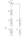
- FIG. 2 is a block diagram showing the schematic configuration of the medical image processing apparatus according to the first embodiment.
- the medical image processing apparatus 100 shown in FIG. 2 includes a first image acquisition unit 101, a first likelihood distribution calculation unit 102, a tracking availability determination unit 103, a tracking unit 104, a second image acquisition unit 105, and a second likelihood distribution calculator 106 .
- the first image acquisition unit 101 acquires a plurality of first images, which are fluoroscopic images of the patient P and taken in different imaging directions.
- the first image may be an X-ray fluoroscopic image captured by the radiation detector 30 in the positioning of the patient P described above, or a virtual image obtained from a three-dimensional CT image captured in advance before performing radiation therapy. It may be a DRR image obtained by reconstructing an X-ray fluoroscopic image.
- the first likelihood distribution calculation unit 102 calculates a first likelihood distribution indicating the likelihood distribution representing the likelihood of being a marker (object) in each of the plurality of first images 60 acquired by the first image acquisition unit 101. do.
- FIG. 3 is a diagram showing an example of the first image according to the first embodiment.
- the first image 60 includes an image of a marker 62 placed inside the patient P's body and an image of a lesion 63 inside the patient's P body.
- the first likelihood distribution calculator 102 calculates the likelihood distribution for the tracking region 61 instead of calculating the likelihood distribution for the entire first image 60 .
- the tracking area 61 is an area in which the position of the marker 62 is tracked, and is an area that includes a range in which the marker 62 moves due to movement of the patient P's breathing and heartbeat. In this way, by limiting the target for calculating the first likelihood distribution to a part (tracking area 61) of the first image 60, the processing load of the first likelihood distribution calculation unit 102 can be reduced.
- the tracking area 61 is determined based on the position of the marker 62 designated on the CT image during treatment planning. Also, the tracking area 61 is determined in consideration of a margin based on errors that may occur during actual treatment. For example, the tracking area 61 may be an area obtained by projecting a three-dimensional area with a margin added around the position of the marker 62 on the CT image onto the first image. Also, the tracking area 61 may be determined according to a margin determined in consideration of the patient's condition immediately before treatment.
- the marker 62 is assumed to be a bar-shaped marker in FIG. 3, the shape of the marker 62 is not limited to this. For example, it may be a spherical marker.
- the first likelihood distribution calculation unit 102 stores in advance the image pattern when the marker 62 is projected as a template image, and calculates the likelihood by calculating the degree of similarity between the first image 60 and the template image. do.
- an image of the shadow drawn may be used as the template image.
- the shadow of the marker 62 changes according to the posture of the marker 62 when it is indwelled in the body of the patient P, a plurality of template images depicting the shadow according to the posture of the marker 62 are generated, and a plurality of template images are generated.
- One of the template images may be selected and used.
- the degree of similarity which is a numerical value of likelihood, is represented by pixel values and spatial correlation values between the template image and the first image 60 .
- the similarity may be the reciprocal of the pixel value difference at each corresponding pixel location.
- the similarity may also be a cross-correlation value of corresponding pixel positions.
- the first likelihood distribution calculating unit 102 may generate a discriminator by a machine learning method using a template image including the marker 62 as learning data, and calculate the likelihood using the generated discriminator. good.
- a classifier is generated by preparing a plurality of template images including markers 62 and first images 60 at positions not including markers 62, and learning these using a machine learning technique. By using the generated discriminator, it is possible to discriminate whether or not the marker 62 is included.
- First likelihood distribution calculation section 102 calculates real values calculated using these machine learning methods as likelihoods.
- the real value for example, the distance to the identification boundary, the ratio of classifiers determined to include the object, or the Softmax output value may be used.
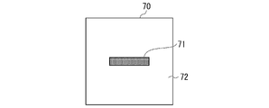
- FIG. 4 is a diagram showing an example of a template used for calculating the degree of separation according to the first embodiment.
- the area is classified into a first area 71 in which the bar-shaped marker 62 is present and a second area 72 other than the first area 71 . That is, the second area 72 is an area where the rod-shaped marker 62 does not exist.
- the histogram of pixel values included in the first image 60 is divided into the histogram of pixel values belonging to the first region 71 and the histogram of pixel values belonging to the second region. 72 and histograms of pixel values belonging to 72, respectively. This is because when the image of the marker 62 captured in the first image 60 overlaps the first region 71, the histogram of the pixel values belonging to the first region 71 has a high frequency of pixel values of dark pixels and the second This is because the pixel value histogram belonging to the area 72 has a high frequency of pixel values of bright pixels.
- the first likelihood distribution calculation unit 102 quantifies the separability of the histogram of pixel values as described above using Fisher's criterion. Then, the first likelihood distribution calculating unit 102 calculates the ratio of the average of the variance of the pixel values of the pixels belonging to each region (intra-class variance) to the variance of the pixel values between the regions (inter-class variance). is calculated, and this ratio is calculated as the degree of separation. In this way, first likelihood distribution calculation section 102 calculates the degree of separation calculated using template 70 as the likelihood. The first likelihood distribution calculation unit 102 uses the calculated likelihoods to calculate a first likelihood distribution indicating the distribution of likelihoods in each of the plurality of first images 60 acquired by the first image acquisition unit 101. do.
- the tracking availability determination unit 103 determines whether the marker 62 can be tracked. Specifically, the tracking availability determination unit 103 calculates the tracking difficulty in each shooting direction of the first image 60 based on the first likelihood distribution calculated by the first likelihood distribution calculation unit 102 . Further, when the tracking difficulty level is higher than a predetermined threshold, the tracking availability determination unit 103 determines that the marker 62 cannot be tracked.
- the tracking availability determination unit 103 calculates the tracking difficulty level based on the statistics of the first likelihood distribution.
- the statistic is, for example, a primary statistic such as the mean value of the first likelihood distribution and the variance of the first likelihood distribution, but is not limited to this.
- the statistic may be the maximum value of the first likelihood distribution, or a value calculated by a linear expression integrating these numerical values.
- the tracking possibility determination unit 103 calculates the tracking difficulty by focusing on the statistics of the first likelihood distribution around the position of the marker 62. You may The tracking propriety determination unit 103 outputs the determination result of the propriety of tracking of the marker 62 for each imaging direction to the tracking unit 104 and the second image acquisition unit 105 .
- the tracking unit 104 tracks the position of the marker 62 in the second image acquired by the second image acquisition unit 105 according to the determination result of the tracking availability determination unit 103 . Details of the tracking process by the tracking unit 104 will be described later.
- the second image acquisition unit 105 acquires a plurality of second images, which are fluoroscopic images of the patient P generated at times different from the first images and taken in different imaging directions.
- the first image described above is a fluoroscopic image generated based on a three-dimensional image of the patient P captured during treatment planning, or a fluoroscopic image captured from the same imaging direction as the second image immediately before treatment.
- 2 images are fluoroscopic images captured by the radiation detector 30 during the treatment of the patient P; To track the marker 62, the second image is taken repeatedly at predetermined time intervals.
- the imaging direction of the first image is preferably the same as the imaging direction of the second image.
- the first image is not a fluoroscopic image taken when positioning the patient P, but a fluoroscopic image taken in the same direction as the second image. It may be a DRR image that simulates an image.
- the first image may be the second image captured during the previous treatment, or the image captured from the same direction as the second image immediately before the treatment.
- the first image may be a moving image of one or more breathing cycles.
- the second image acquisition unit 105 causes the tracking unit 104 to track the position of the marker 62 based on the determination result of the tracking possibility determination unit 103 before treatment is performed on the patient P by irradiation of the treatment beam B. determine the shooting direction of the second image used for For example, when the determination result for the first image in the imaging direction of the radiation detector 30-1 is “trackable” and the determination result for the first image in the imaging direction of the radiation detector 30-2 is “trackable”. , the second image acquisition unit 105 acquires both the second image captured by the radiation detector 30-1 and the second image captured by the radiation detector 30-2.
- the second image acquisition unit 105 acquires only the second image captured by the radiation detector 30-1.
- the second image acquisition unit 105 acquires only the second image captured by the radiation detector 30-2.
- the second image acquisition unit 105 does not acquire the second image in the imaging direction determined to be unable to track the marker 62, thereby suppressing the radiation exposure of the patient P. , the success rate of tracking the marker 62 can be improved.
- the second likelihood distribution calculation unit 106 calculates a second likelihood distribution indicating the distribution of likelihoods in the second image acquired by the second image acquisition unit 105 .
- the second likelihood distribution calculator 106 does not calculate the second likelihood distribution for the entire second image, but calculates the second likelihood distribution for the tracking area 61 in the second image.
- the method for calculating the second likelihood distribution is the same as the method for calculating the first likelihood distribution, so the description is omitted.
- the tracking unit 104 determines the position of the marker 62 in the second image based on the second likelihood distribution calculated by the second likelihood distribution calculating unit 106. For example, the tracking unit 104 determines that the position of the marker 62 is the position of the maximum value in the second likelihood distribution.
- the tracking unit 104 may determine that the position where the likelihood distribution on the epipolar line has the maximum value is the position of the marker 62 .
- the tracking unit 104 may geometrically transform the position of the marker 62 into three-dimensional coordinates and calculate them.
- the tracking unit 104 determines the irradiation timing of the treatment beam B based on the determined position of the marker 62 .
- the positional relationship between the marker 62 and the lesion 63 can be identified from the fluoroscopic image of the patient P acquired during treatment planning. For this reason, the tracking unit 104 instructs the irradiation of the treatment beam B when the position of the lesion 63 in the body of the patient P specified based on the position of the marker 62 is located within a predetermined range.
- An instruction signal is transmitted to the irradiation control device 50 .
- the irradiation control device 50 irradiates the therapeutic beam B from the therapeutic beam irradiation gate 40 according to the irradiation instruction signal received from the medical image processing device 100 .
- the lesion 63 inside the body of the patient P can be irradiated with the treatment beam B.
- the tracking unit 104 does not transmit the irradiation instruction signal to the irradiation control device 50 when the position of the lesion 63 inside the body of the patient P specified based on the position of the marker 62 is not located within the predetermined range. .
- the tracking unit 104 does not transmit the irradiation instruction signal to the irradiation control device 50 when the position of the lesion 63 inside the body of the patient P specified based on the position of the marker 62 is not located within the predetermined range. .
- a hardware processor such as a CPU (Central Processing Unit) and a storage device ( A storage device including a non-transitory storage medium) may be provided, and various functions may be realized by the processor executing the program.
- some or all of the functions of the components provided in the medical image processing apparatus 100 described above are implemented by LSI (Large Scale Integration), ASIC (Application Specific Integrated Circuit), FPGA (Field-Programmable Gate Array), GPU (Graphics Processing Unit) or the like (including circuitry), or various functions may be realized by cooperation of software and hardware.
- LSI Large Scale Integration
- ASIC Application Specific Integrated Circuit
- FPGA Field-Programmable Gate Array
- GPU Graphics Processing Unit
- some or all of the functions of the components provided in the medical image processing apparatus 100 described above may be realized by a dedicated LSI.
- the program (software) is a storage device (non-transitory storage device having a storage medium), or may be stored in a detachable storage medium (non-transitory storage medium) such as a DVD or CD-ROM, and the storage medium is attached to the treatment system 1. It may be installed in the storage device provided in the treatment system 1 by being attached to the provided drive device. Alternatively, the program (software) may be pre-downloaded from another computer device via a network and installed in a storage device provided in the treatment system 1 .
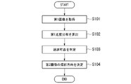
- FIG. 5 is a flow chart showing the operation of the medical image processing apparatus in the pre-treatment stage of patient treatment according to the first embodiment. The processing according to this flow chart is executed by the medical image processing apparatus 100 at a stage before treatment is performed on the patient P by irradiation of the treatment beam B.
- FIG. 5 is a flow chart showing the operation of the medical image processing apparatus in the pre-treatment stage of patient treatment according to the first embodiment. The processing according to this flow chart is executed by the medical image processing apparatus 100 at a stage before treatment is performed on the patient P by irradiation of the treatment beam B.
- the first image acquisition unit 101 acquires a plurality of first images, which are fluoroscopic images of the patient P and taken in different imaging directions (S101).
- the first image may be an X-ray fluoroscopic image captured by the radiation detector 30 during positioning of the patient P, or a three-dimensional CT image captured in advance before radiotherapy. It may also be a DRR image obtained by virtually reconstructing an X-ray fluoroscopic image from .
- the first likelihood distribution calculation unit 102 calculates a first likelihood distribution indicating the distribution of likelihoods representing the likelihood of being a marker (object) in each of the plurality of first images 60 acquired by the first image acquisition unit 101.
- a distribution is calculated (S102).
- the first likelihood distribution calculator 102 does not calculate the likelihood distribution in the entire first image 60, but calculates the likelihood distribution in the tracking area 61 shown in FIG.
- the tracking possibility determination unit 103 determines whether the marker 62 can be tracked based on the first likelihood distribution calculated by the first likelihood distribution calculation unit 102 (S103). For example, the tracking possibility determination unit 103 calculates the tracking difficulty in each shooting direction of the first image 60 based on the first likelihood distribution calculated by the first likelihood distribution calculation unit 102 . Further, when the tracking difficulty level is higher than a predetermined threshold, the tracking availability determination unit 103 determines that the marker 62 cannot be tracked.
- the second image acquisition unit 105 determines the imaging direction of the second image based on the determination result of the tracking availability determination unit 103 (S104), and ends the processing according to this flowchart. Note that when the patient P is treated by the irradiation of the treatment beam B, the marker 62 is tracked based on the second image corresponding to the imaging direction determined in step S104.
- FIG. 6 is a flowchart showing operations of the medical image processing apparatus during treatment of a patient according to the first embodiment. The processing according to this flowchart is repeatedly executed at predetermined time intervals by the medical image processing apparatus 100 at the stage where the patient P is being treated by the irradiation of the treatment beam B.
- FIG. 6 is a flowchart showing operations of the medical image processing apparatus during treatment of a patient according to the first embodiment. The processing according to this flowchart is repeatedly executed at predetermined time intervals by the medical image processing apparatus 100 at the stage where the patient P is being treated by the irradiation of the treatment beam B.
- the second image acquisition unit 105 acquires a second image corresponding to the shooting direction determined in step S104 (S201).
- the second image is an image captured by the radiation detector 30 during treatment for the patient P.
- the second image acquisition unit 105 does not acquire second images for shooting directions in which the tracking difficulty is higher than a predetermined threshold, and acquires only second images in which the tracking difficulty is equal to or lower than the predetermined threshold. do.
- the second likelihood distribution calculation unit 106 calculates a second likelihood distribution indicating the distribution of likelihoods in the second image acquired by the second image acquisition unit 105 (S202).
- the method for calculating the second likelihood distribution is the same as the method for calculating the first likelihood distribution.
- the tracking unit 104 determines the position of the marker 62 (object) in the second image based on the second likelihood distribution calculated by the second likelihood distribution calculating unit 106 (S203). For example, the tracking unit 104 determines that the position of the marker 62 is the position of the maximum value in the second likelihood distribution.
- the tracking unit 104 determines the irradiation timing of the treatment beam B based on the determined position of the marker 62 (object) (S204). For example, the tracking unit 104 provides an irradiation instruction for instructing irradiation of the therapeutic beam B when the position of the lesion 63 in the body of the patient P identified based on the position of the marker 62 is located within a predetermined range.
- a signal is sent to the illumination control device 50 .
- the irradiation control device 50 irradiates the treatment beam B from the treatment beam irradiation gate 40 according to the irradiation instruction signal received from the medical image processing device 100 .
- the first image acquisition unit 101 acquires a plurality of first images, which are fluoroscopic images of the patient P and taken in different imaging directions.
- the second image acquisition unit 105 acquires a plurality of second images, which are fluoroscopic images of the patient P generated at times different from the first images and taken in different imaging directions.
- the first likelihood distribution calculation unit 102 calculates a first likelihood distribution indicating the likelihood distribution representing object-likeness in each of the plurality of first images acquired by the first image acquisition unit 101 .
- the tracking possibility determination unit 103 determines whether the object can be tracked.
- the tracking unit 104 tracks the position of the object in the second image acquired by the second image acquisition unit 105 according to the determination result of the tracking availability determination unit 103 . This allows highly accurate tracking of objects within the patient's body from the fluoroscopic image of the patient.
- the second image acquisition unit 105 determines the shooting direction of the second image based on the determination result of the tracking availability determination unit 103 .
- the tracking unit 104 determines a tracking area, which is an area for tracking the position of the object, based on the determination result of the tracking availability determination unit 103 . This allows objects within the patient's body to be tracked with greater accuracy. The second embodiment will be described in detail below.
- FIG. 7 is a block diagram showing a schematic configuration of a medical image processing apparatus according to the second embodiment.
- parts corresponding to those in FIG. 2 are denoted by the same reference numerals, and descriptions thereof are omitted.
- the tracking availability determination unit 103 determines whether the marker 62 can be tracked. Specifically, the tracking availability determination unit 103 calculates the tracking difficulty in each shooting direction of the first image 60 based on the first likelihood distribution calculated by the first likelihood distribution calculation unit 102 . Since the method of calculating the tracking difficulty is the same as in the first embodiment, the description is omitted. Further, when the tracking difficulty level is higher than a predetermined threshold, the tracking availability determination unit 103 determines that the marker 62 cannot be tracked. After that, the tracking propriety determination unit 103 outputs to the tracking unit 104 the determination result of whether the marker 62 can be tracked for each shooting direction. On the other hand, unlike the first embodiment, the tracking availability determination unit 103 does not output the determination result to the second image acquisition unit 105 .
- the second image acquisition unit 105 acquires a plurality of second images, which are fluoroscopic images of the patient P generated at times different from the first images and taken in different imaging directions.
- the second image is an image captured by the radiation detector 30 during treatment of the patient P.
- FIG. Specifically, the second image acquisition unit 105 acquires both the fluoroscopic image captured by the radiation detector 30-1 and the fluoroscopic image captured by the radiation detector 30-2 as the second image.
- the second likelihood distribution calculation unit 106 calculates a second likelihood distribution indicating the distribution of likelihoods in the second image acquired by the second image acquisition unit 105 . Specifically, the second likelihood distribution calculation unit 106 calculates the likelihood distribution in the fluoroscopic image (second image) captured by the radiation detector 30-1 and the fluoroscopic image captured by the radiation detector 30-2. The distribution of likelihood in (second image) is calculated as a second likelihood distribution. Here, the second likelihood distribution calculator 106 does not calculate the second likelihood distribution for the entire second image, but calculates the second likelihood distribution for the tracking area 61 in the second image. The method for calculating the second likelihood distribution is the same as the method for calculating the first likelihood distribution, so the description is omitted.
- the tracking unit 104 defines a tracking area 61 (FIG. 3), which is an area for tracking the position of the marker 62, based on the determination result of the tracking possibility determination unit 103. Specifically, the tracking unit 104 places the tracking area 61 on the epipolar line for the second image in the imaging direction in which the tracking availability determination unit 103 determines that the tracking difficulty of the marker 62 is higher than a predetermined threshold. limit.
- the tracking difficulty in the imaging direction of the radiation detector 30-1 is higher than a predetermined threshold, and the tracking difficulty in the imaging direction of the radiation detector 30-2 is less than or equal to the predetermined threshold.
- the tracking unit 104 limits the tracking area 61 to the area on the epipolar line with respect to the second image captured by the radiation detector 30-1.
- the shooting direction in which the marker 62 is easily tracked is determined based on the tracking difficulty, and from the second image in the shooting direction in which tracking is difficult, the tracking region 61 is limited to the region on the epipolar line, and the marker 62 is moved. Chase.
- the medical image processing apparatus 200 of this embodiment can improve the tracking accuracy of the marker 62 .
- FIG. 8 is a flow chart showing the operation of the medical image processing apparatus in the pre-treatment stage of patient treatment according to the second embodiment.
- the processing according to this flow chart is executed by the medical image processing apparatus 200 at a stage before treatment is performed on the patient P by irradiating the treatment beam B.
- FIG. Note that steps S301 to S303 in FIG. 8 are the same as steps S101 to S103 in FIG. 5, so description thereof will be omitted.
- the tracking availability determination unit 103 determines whether or not there is a tracking difficulty level higher than a predetermined threshold among the tracking difficulty levels in each shooting direction calculated in step S303 (S304). If there is no tracking difficulty higher than the predetermined threshold (S304: NO), the tracking unit 104 terminates the processing according to this flowchart without changing the tracking area 61. FIG. On the other hand, if there is a tracking difficulty higher than the predetermined threshold (S304: YES), the tracking unit 104 determines the position of the marker 62 in the shooting direction with the lowest tracking difficulty and the shooting direction with the lowest tracking difficulty. A straight line connecting the position (the position of the radiation detector 30) is calculated as an epipolar line (S305). After that, the tracking unit 104 limits the tracking area 61 in the shooting direction in which the tracking difficulty is higher than a predetermined threshold to the area on the epipolar line calculated in step S305 (S306), and ends the processing according to this flowchart.
- the tracking unit 104 does not change the tracking area 61 for the second image in the shooting direction for which the tracking difficulty is determined to be equal to or less than the predetermined threshold.
- the tracking unit 104 sets the tracking area 61 to the position of the marker 62 in the shooting direction with the lowest tracking difficulty for the second image in the shooting direction determined to have the tracking difficulty higher than the predetermined threshold. limited to the region on the epipolar line calculated based on Thereby, the medical image processing apparatus 200 of this embodiment can improve the tracking accuracy of the marker 62 .
- an irradiation control device 50 for controlling the treatment beam irradiation gate 40 is provided.
- the irradiation control device 50 is not provided in the treatment system 1, and the radiation therapy device 300 is provided with the function of controlling the treatment beam irradiation gate 40.
- FIG. The third embodiment will be described in detail below.
- FIG. 9 is a block diagram showing a schematic configuration of a radiotherapy apparatus according to the third embodiment.
- a radiotherapy apparatus 300 according to the third embodiment includes an irradiation control unit 301 .
- the tracking unit 104 determines the position of the marker 62 in the second image based on the second likelihood distribution calculated by the second likelihood distribution calculating unit 106. For example, the tracking unit 104 determines that the position of the marker 62 is the position of the maximum value in the second likelihood distribution.
- the tracking unit 104 determines the irradiation timing of the treatment beam B based on the determined position of the marker 62 .
- the positional relationship between the marker 62 and the lesion 63 can be identified from the fluoroscopic image of the patient P acquired during treatment planning. For this reason, the tracking unit 104 instructs the irradiation of the treatment beam B when the position of the lesion 63 in the body of the patient P specified based on the position of the marker 62 is located within a predetermined range.
- An instruction signal is output to the irradiation control unit 301 .
- the irradiation control unit 301 irradiates the treatment beam B from the treatment beam irradiation gate 40 according to the irradiation instruction signal output from the tracking unit 104 .
- the lesion 63 inside the body of the patient P can be irradiated with the treatment beam B.
- the tracking unit 104 does not output the irradiation instruction signal to the irradiation control unit 301 when the position of the lesion 63 inside the body of the patient P specified based on the position of the marker 62 is not located within the predetermined range. .
- the tracking unit 104 does not output the irradiation instruction signal to the irradiation control unit 301 when the position of the lesion 63 inside the body of the patient P specified based on the position of the marker 62 is not located within the predetermined range. .
- FIG. 10 is a flow chart showing the operation of the radiotherapy apparatus during treatment of a patient according to the third embodiment.
- the processing according to this flowchart is repeatedly executed by the radiotherapy apparatus 300 at predetermined time intervals when the patient P is being treated by irradiation with the treatment beam B.
- FIG. Note that steps S401 to S403 in FIG. 10 are the same as steps S201 to S203 in FIG. 6, so description thereof will be omitted.
- the irradiation control unit 301 irradiates the treatment beam B from the treatment beam irradiation gate 40 according to the position of the marker 62 (object) determined by the tracking unit 104 in step S403. For example, the irradiation control unit 301 controls the treatment beam B from the treatment beam irradiation gate 40 when the position of the lesion 63 in the body of the patient P specified based on the position of the marker 62 is located within a predetermined range. to irradiate.
- the radiotherapy apparatus 300 includes the irradiation control unit 301 that controls the treatment beam irradiation gate 40 in addition to the functions of the medical image processing apparatus 100 according to the first embodiment.
- the radiotherapy apparatus 300 of this embodiment can also improve the tracking accuracy of the markers 62 as in the first embodiment.
- the object tracked by the tracking unit 104 is a metal marker indwelled in the body of the patient P, but it may be a lesion in the body of the patient P.
- an image including the entire lesion or part of the lesion may be cut out from the first image and used as the template image.
- the first image is a DRR image generated from a CT image containing treatment plan information
- the position of the lesion in the CT image is included in the treatment plan information, so the image on which this lesion is projected is used as a template image.
- the first image is an X-ray fluoroscopic image captured by the radiation detector 30 during positioning of the patient P
- the DRR image and the position of the patient P match.
- a fluoroscopy image may be cut out and used as a template image.
- the tracking availability determination unit 103 may present the tracking difficulty level in each shooting direction to the user using a notification unit (not shown). For example, the tracking availability determination unit 103 may notify the user of a shooting direction with a low tracking difficulty when the user plans the shooting direction. This allows the user to estimate the success rate of the respiratory gated irradiation method and to determine whether or not the tracking of the marker 62 should be limited to only the second image of one imaging direction.
- the medical image processing apparatuses 100 and 200 and the radiation therapy apparatus 300 described above can also be realized by using, for example, a general-purpose computer device as basic hardware. That is, the first image acquisition unit 101, the first likelihood distribution calculation unit 102, the tracking availability determination unit 103, the tracking unit 104, the second image acquisition unit 105, the second likelihood distribution calculation unit 106, and the irradiation control unit 301 , can be realized by causing a processor installed in the computer device to execute a program.
- the medical image processing apparatuses 100 and 200 and the radiotherapy apparatus 300 may be realized by installing the above programs in advance in a computer device, storing them in a storage medium such as a CD-ROM, or It may be realized by distributing the above program via a network and appropriately installing the program in a computer device.
- B and C can be realized by appropriately using a memory built in or external to the computer device, a hard disk, or a storage medium such as a CD-R, a CD-RW, a DVD-RAM, and a DVD-R. can be done.
- Treatment system 100 Medical image processing apparatus 101 First image acquisition unit 102 First likelihood distribution calculation unit 103 Tracking possibility determination unit 104 Tracking unit 105 Second image acquisition unit 106 Second likelihood distribution calculation unit 200 Medical image processing apparatus 300 Radiotherapy apparatus 301 Irradiation control unit
Landscapes
- Health & Medical Sciences (AREA)
- Engineering & Computer Science (AREA)
- Biomedical Technology (AREA)
- Life Sciences & Earth Sciences (AREA)
- Veterinary Medicine (AREA)
- Pathology (AREA)
- Nuclear Medicine, Radiotherapy & Molecular Imaging (AREA)
- Animal Behavior & Ethology (AREA)
- General Health & Medical Sciences (AREA)
- Public Health (AREA)
- Radiology & Medical Imaging (AREA)
- Surgery (AREA)
- Oral & Maxillofacial Surgery (AREA)
- Heart & Thoracic Surgery (AREA)
- Medical Informatics (AREA)
- Molecular Biology (AREA)
- Multimedia (AREA)
- Computer Vision & Pattern Recognition (AREA)
- Physics & Mathematics (AREA)
- General Physics & Mathematics (AREA)
- Theoretical Computer Science (AREA)
- Radiation-Therapy Devices (AREA)
- Apparatus For Radiation Diagnosis (AREA)
Abstract
Description
図1は、第1の実施形態に係る治療システムの概略構成を示すブロック図である。治療システム1は、例えば、治療台10と、寝台制御部11と、2つの放射線源20(放射線源20-1および放射線源20-2)と、2つの放射線検出器30(放射線検出器30-1および放射線検出器30-2)と、治療ビーム照射門40と、照射制御装置50と、医用画像処理装置100とを備える。
第1の実施形態において、第2画像取得部105は、追跡可否判定部103の判定結果に基づいて、第2画像の撮影方向を決定することとした。これに対し、第2の実施形態において、追跡部104は、追跡可否判定部103の判定結果に基づいて、オブジェクトの位置を追跡する領域である追跡領域を定めることとする。これによって、患者の体内のオブジェクトを、より高精度に追跡することができる。以下、第2の実施形態について詳細に説明する。
第1の実施形態および第2の実施形態において、治療ビーム照射門40を制御する照射制御装置50が設けられることとした。これに対し、第3の実施形態においては、照射制御装置50が治療システム1に設けられておらず、放射線治療装置300が治療ビーム照射門40を制御する機能を備えることとする。以下、第3の実施形態について詳細に説明する。
100・・・医用画像処理装置
101・・・第1画像取得部
102・・・第1尤度分布算出部
103・・・追跡可否判定部
104・・・追跡部
105・・・第2画像取得部
106・・・第2尤度分布算出部
200・・・医用画像処理装置
300・・・放射線治療装置
301・・・照射制御部
Claims (11)
- 患者の体内のオブジェクトの位置を追跡する医用画像処理装置であって、
前記患者の透視画像であって、撮影方向の異なる複数の第1画像を取得する第1画像取得部と、
前記第1画像とは異なる時刻に生成された前記患者の透視画像であって、撮影方向の異なる複数の第2画像を取得する第2画像取得部と、
前記第1画像取得部によって取得された前記複数の第1画像のそれぞれにおける、前記オブジェクトらしさを表す尤度の分布を示す第1尤度分布を算出する第1尤度分布算出部と、
前記第1尤度分布算出部によって算出された前記第1尤度分布に基づいて、前記オブジェクトの追跡の可否を判定する追跡可否判定部と、
前記追跡可否判定部の判定結果に応じて、前記第2画像取得部によって取得された前記第2画像における前記オブジェクトの位置を追跡する追跡部と、
を備える医用画像処理装置。 - 前記第2画像取得部は、前記追跡可否判定部の判定結果に基づいて、前記第2画像の撮影方向を決定する、請求項1に記載の医用画像処理装置。
- 前記第2画像取得部は、前記患者に対して治療が行われる前に、前記追跡部による前記オブジェクトの位置の追跡に使用される前記第2画像の撮影方向を決定する、請求項2に記載の医用画像処理装置。
- 前記第2画像における前記尤度の分布を示す第2尤度分布を算出する第2尤度分布算出部を更に備え、
前記追跡部は、前記第2尤度分布算出部によって算出された前記第2尤度分布に基づいて、前記第2画像における前記オブジェクトの位置を判定する、請求項1に記載の医用画像処理装置。 - 前記追跡部は、前記追跡可否判定部の判定結果に基づいて、前記オブジェクトの位置を追跡する領域である追跡領域を定める、請求項1に記載の医用画像処理装置。
- 前記追跡可否判定部は、前記第2画像における前記オブジェクトの追跡の難易度を示す追跡難易度を算出し、
前記追跡部は、前記追跡可否判定部によって算出された前記追跡難易度が所定の閾値より高い前記第2画像に対して、前記追跡領域をエピポーラ線上の領域に限定する、請求項5に記載の医用画像処理装置。 - 前記オブジェクトは金属製マーカーである、請求項1から請求項6のうちのいずれか1項に記載の医用画像処理装置。
- 前記第1画像は、治療計画時に撮影された前記患者の3次元画像に基づいて生成された透視画像、または治療直前に前記第2画像と同じ撮影方向から撮影された透視画像であり、
前記第2画像は、前記患者に対する治療中に撮影された透視画像である、
請求項1から請求項7のうちのいずれか1項に記載の医用画像処理装置。 - 患者の体内のオブジェクトの位置を追跡する医用画像処理方法であって、
前記患者の透視画像であって、撮影方向の異なる複数の第1画像を取得する第1画像取得工程と、
前記第1画像とは異なる時刻に生成された前記患者の透視画像であって、撮影方向の異なる複数の第2画像を取得する第2画像取得工程と、
前記第1画像取得工程によって取得された前記複数の第1画像のそれぞれにおける、前記オブジェクトらしさを表す尤度の分布を示す第1尤度分布を算出する第1尤度分布算出工程と、
前記第1尤度分布算出工程によって算出された前記第1尤度分布に基づいて、前記オブジェクトの追跡の可否を判定する追跡可否判定工程と、
前記追跡可否判定工程の判定結果に応じて、前記第2画像取得工程によって取得された前記第2画像における前記オブジェクトの位置を追跡する追跡工程と、
を備える医用画像処理方法。 - 患者の体内のオブジェクトの位置を追跡する医用画像処理プログラムであって、
コンピュータに、
前記患者の透視画像であって、撮影方向の異なる複数の第1画像を取得する第1画像取得工程と、
前記第1画像とは異なる時刻に生成された前記患者の透視画像であって、撮影方向の異なる複数の第2画像を取得する第2画像取得工程と、
前記第1画像取得工程によって取得された前記複数の第1画像のそれぞれにおける、前記オブジェクトらしさを表す尤度の分布を示す第1尤度分布を算出する第1尤度分布算出工程と、
前記第1尤度分布算出工程によって算出された前記第1尤度分布に基づいて、前記オブジェクトの追跡の可否を判定する追跡可否判定工程と、
前記追跡可否判定工程の判定結果に応じて、前記第2画像取得工程によって取得された前記第2画像における前記オブジェクトの位置を追跡する追跡工程と、
を実行させる医用画像処理プログラム。 - 患者の体内のオブジェクトの位置を追跡しつつ、前記患者に放射線を照射する放射線治療装置であって、
前記患者の透視画像であって、撮影方向の異なる複数の第1画像を取得する第1画像取得部と、
前記第1画像とは異なる時刻に生成された前記患者の透視画像であって、撮影方向の異なる複数の第2画像を取得する第2画像取得部と、
前記第1画像取得部によって取得された前記複数の第1画像のそれぞれにおける、前記オブジェクトらしさを表す尤度の分布を示す第1尤度分布を算出する第1尤度分布算出部と、
前記第1尤度分布算出部によって算出された前記第1尤度分布に基づいて、前記オブジェクトの追跡の可否を判定する追跡可否判定部と、
前記追跡可否判定部の判定結果に応じて、前記第2画像取得部によって取得された前記第2画像における前記オブジェクトの位置を追跡する追跡部と、
前記追跡部によって追跡された前記オブジェクトの位置に応じて、前記放射線の照射を制御する照射制御部と、
を備える放射線治療装置。
Priority Applications (3)
| Application Number | Priority Date | Filing Date | Title |
|---|---|---|---|
| CN202280009455.2A CN116782984A (zh) | 2021-03-12 | 2022-02-22 | 医用图像处理装置、医用图像处理方法、医用图像处理程序以及放射线治疗装置 |
| KR1020237022587A KR102961664B1 (ko) | 2021-03-12 | 2022-02-22 | 의료용 화상 처리 장치, 의료용 화상 처리 방법, 컴퓨터 판독가능한 기억 매체, 및 방사선 치료 장치 |
| US18/349,397 US12605566B2 (en) | 2021-03-12 | 2023-07-10 | Medical image processing device, medical image processing method, medical image processing program, and radiation therapy device |
Applications Claiming Priority (2)
| Application Number | Priority Date | Filing Date | Title |
|---|---|---|---|
| JP2021039812A JP7711888B2 (ja) | 2021-03-12 | 2021-03-12 | 医用画像処理装置、医用画像処理方法、医用画像処理プログラム、および放射線治療装置 |
| JP2021-039812 | 2021-03-12 |
Related Child Applications (1)
| Application Number | Title | Priority Date | Filing Date |
|---|---|---|---|
| US18/349,397 Continuation US12605566B2 (en) | 2021-03-12 | 2023-07-10 | Medical image processing device, medical image processing method, medical image processing program, and radiation therapy device |
Publications (1)
| Publication Number | Publication Date |
|---|---|
| WO2022190846A1 true WO2022190846A1 (ja) | 2022-09-15 |
Family
ID=83227788
Family Applications (1)
| Application Number | Title | Priority Date | Filing Date |
|---|---|---|---|
| PCT/JP2022/007094 Ceased WO2022190846A1 (ja) | 2021-03-12 | 2022-02-22 | 医用画像処理装置、医用画像処理方法、医用画像処理プログラム、および放射線治療装置 |
Country Status (4)
| Country | Link |
|---|---|
| US (1) | US12605566B2 (ja) |
| JP (1) | JP7711888B2 (ja) |
| CN (1) | CN116782984A (ja) |
| WO (1) | WO2022190846A1 (ja) |
Families Citing this family (1)
| Publication number | Priority date | Publication date | Assignee | Title |
|---|---|---|---|---|
| JP7791002B2 (ja) * | 2022-02-18 | 2025-12-23 | 株式会社日立ハイテク | 位置決め装置、放射線治療装置及び位置決め方法 |
Citations (4)
| Publication number | Priority date | Publication date | Assignee | Title |
|---|---|---|---|---|
| JP2015029793A (ja) * | 2013-08-05 | 2015-02-16 | 株式会社日立製作所 | 放射線治療システム |
| JP2019154738A (ja) * | 2018-03-12 | 2019-09-19 | 東芝エネルギーシステムズ株式会社 | 医用画像処理装置、治療システム、および医用画像処理プログラム |
| JP2019528149A (ja) * | 2016-08-29 | 2019-10-10 | アキュレイ インコーポレイテッド | 回転撮像及び追跡システムにおけるオンライン角度選択 |
| JP2021010650A (ja) * | 2019-07-08 | 2021-02-04 | 株式会社日立製作所 | 動体追跡装置および放射線治療システム、ならびに動体の追跡方法 |
Family Cites Families (7)
| Publication number | Priority date | Publication date | Assignee | Title |
|---|---|---|---|---|
| US9460512B2 (en) * | 2006-05-12 | 2016-10-04 | Toshiba Medical Systems Corporation | Three-dimensional image processing apparatus and reconstruction region specification method |
| CN105828700B (zh) * | 2013-12-09 | 2018-07-06 | Smi创新传感技术有限公司 | 操作眼睛跟踪装置的方法和提供主动照明控制用于改进的眼睛跟踪稳定性的眼睛跟踪装置 |
| JP6849966B2 (ja) | 2016-11-21 | 2021-03-31 | 東芝エネルギーシステムズ株式会社 | 医用画像処理装置、医用画像処理方法、医用画像処理プログラム、動体追跡装置および放射線治療システム |
| WO2018125812A1 (en) * | 2017-01-02 | 2018-07-05 | Gauss Surgical, Inc. | Tracking surgical items with prediction of duplicate imaging of items |
| WO2019064337A1 (ja) * | 2017-09-26 | 2019-04-04 | 三菱電機株式会社 | 粒子線治療装置 |
| WO2019072361A1 (en) * | 2017-10-09 | 2019-04-18 | Brainlab Ag | STEREO MONITORING OF SOFT TISSUE |
| US10631818B2 (en) * | 2017-12-13 | 2020-04-28 | Carestream Health, Inc. | Mobile radiography calibration for tomosynthesis using epipolar geometry |
-
2021
- 2021-03-12 JP JP2021039812A patent/JP7711888B2/ja active Active
-
2022
- 2022-02-22 CN CN202280009455.2A patent/CN116782984A/zh active Pending
- 2022-02-22 WO PCT/JP2022/007094 patent/WO2022190846A1/ja not_active Ceased
-
2023
- 2023-07-10 US US18/349,397 patent/US12605566B2/en active Active
Patent Citations (4)
| Publication number | Priority date | Publication date | Assignee | Title |
|---|---|---|---|---|
| JP2015029793A (ja) * | 2013-08-05 | 2015-02-16 | 株式会社日立製作所 | 放射線治療システム |
| JP2019528149A (ja) * | 2016-08-29 | 2019-10-10 | アキュレイ インコーポレイテッド | 回転撮像及び追跡システムにおけるオンライン角度選択 |
| JP2019154738A (ja) * | 2018-03-12 | 2019-09-19 | 東芝エネルギーシステムズ株式会社 | 医用画像処理装置、治療システム、および医用画像処理プログラム |
| JP2021010650A (ja) * | 2019-07-08 | 2021-02-04 | 株式会社日立製作所 | 動体追跡装置および放射線治療システム、ならびに動体の追跡方法 |
Also Published As
| Publication number | Publication date |
|---|---|
| US12605566B2 (en) | 2026-04-21 |
| JP7711888B2 (ja) | 2025-07-23 |
| CN116782984A (zh) | 2023-09-19 |
| US20230347180A1 (en) | 2023-11-02 |
| JP2022139429A (ja) | 2022-09-26 |
| KR20230117404A (ko) | 2023-08-08 |
Similar Documents
| Publication | Publication Date | Title |
|---|---|---|
| US11896850B2 (en) | Online angle selection in rotational imaging and tracking systems | |
| US11691029B2 (en) | Offline angle selection in rotational imaging and tracking systems | |
| US11318328B2 (en) | Presenting a sequence of images associated with a motion model | |
| US10853940B2 (en) | Manipulation of a respiratory model via adjustment of parameters associated with model images | |
| CN104337536B (zh) | 放射线治疗系统 | |
| US10143431B2 (en) | Medical image processing apparatus and method, and radiotherapeutic apparatus | |
| US20210042917A1 (en) | Medical image processing device, treatment system, and storage medium | |
| JP7093075B2 (ja) | 医用画像処理装置、医用画像処理方法、およびプログラム | |
| JP7311109B2 (ja) | 医用画像処理装置、医用画像処理プログラム、医用装置、および治療システム | |
| EP3765153B1 (en) | Limiting imaging radiation dose and improving image quality | |
| JP7711888B2 (ja) | 医用画像処理装置、医用画像処理方法、医用画像処理プログラム、および放射線治療装置 | |
| KR102961664B1 (ko) | 의료용 화상 처리 장치, 의료용 화상 처리 방법, 컴퓨터 판독가능한 기억 매체, 및 방사선 치료 장치 | |
| JP2026081755A (ja) | 医用画像処理装置、治療システム、医用画像処理方法、プログラム、および記録媒体 | |
| WO2026100186A1 (ja) | 医用画像処理装置、治療システム、医用画像処理方法、プログラム、および記録媒体 | |
| WO2024117129A1 (ja) | 医用画像処理装置、治療システム、医用画像処理方法、およびプログラム | |
| JP2021041089A (ja) | 医用画像処理装置、x線画像処理システム、および、学習モデルの生成方法 |
Legal Events
| Date | Code | Title | Description |
|---|---|---|---|
| 121 | Ep: the epo has been informed by wipo that ep was designated in this application |
Ref document number: 22766809 Country of ref document: EP Kind code of ref document: A1 |
|
| ENP | Entry into the national phase |
Ref document number: 20237022587 Country of ref document: KR Kind code of ref document: A |
|
| WWE | Wipo information: entry into national phase |
Ref document number: 202280009455.2 Country of ref document: CN |
|
| NENP | Non-entry into the national phase |
Ref country code: DE |
|
| 122 | Ep: pct application non-entry in european phase |
Ref document number: 22766809 Country of ref document: EP Kind code of ref document: A1 |