WO2022186081A1 - Joint device - Google Patents
Joint device Download PDFInfo
- Publication number
- WO2022186081A1 WO2022186081A1 PCT/JP2022/007967 JP2022007967W WO2022186081A1 WO 2022186081 A1 WO2022186081 A1 WO 2022186081A1 JP 2022007967 W JP2022007967 W JP 2022007967W WO 2022186081 A1 WO2022186081 A1 WO 2022186081A1
- Authority
- WO
- WIPO (PCT)
- Prior art keywords
- power
- joint device
- knee
- motor
- power transmission
- Prior art date
Links
- 230000007246 mechanism Effects 0.000 claims abstract description 216
- 230000005540 biological transmission Effects 0.000 claims abstract description 169
- 230000008859 change Effects 0.000 claims abstract description 38
- 230000008878 coupling Effects 0.000 claims description 7
- 238000010168 coupling process Methods 0.000 claims description 7
- 238000005859 coupling reaction Methods 0.000 claims description 7
- 210000002414 leg Anatomy 0.000 abstract description 59
- 210000000629 knee joint Anatomy 0.000 abstract description 47
- 238000004904 shortening Methods 0.000 abstract 3
- 210000004394 hip joint Anatomy 0.000 description 64
- 210000003127 knee Anatomy 0.000 description 59
- 210000000689 upper leg Anatomy 0.000 description 53
- 230000033001 locomotion Effects 0.000 description 14
- 238000010586 diagram Methods 0.000 description 11
- 230000007704 transition Effects 0.000 description 10
- 230000009194 climbing Effects 0.000 description 8
- 238000005452 bending Methods 0.000 description 4
- 230000006835 compression Effects 0.000 description 4
- 238000007906 compression Methods 0.000 description 4
- 210000001699 lower leg Anatomy 0.000 description 4
- 230000001174 ascending effect Effects 0.000 description 3
- 230000009467 reduction Effects 0.000 description 3
- 238000013459 approach Methods 0.000 description 2
- 244000309466 calf Species 0.000 description 2
- 238000001514 detection method Methods 0.000 description 2
- 238000012986 modification Methods 0.000 description 2
- 230000004048 modification Effects 0.000 description 2
- 241001465754 Metazoa Species 0.000 description 1
- 230000009471 action Effects 0.000 description 1
- 230000008602 contraction Effects 0.000 description 1
- 230000007423 decrease Effects 0.000 description 1
- 230000000694 effects Effects 0.000 description 1
- 230000006870 function Effects 0.000 description 1
- 230000005484 gravity Effects 0.000 description 1
- 238000007562 laser obscuration time method Methods 0.000 description 1
- 238000005259 measurement Methods 0.000 description 1
- 210000003205 muscle Anatomy 0.000 description 1
- 230000002093 peripheral effect Effects 0.000 description 1
- 238000005096 rolling process Methods 0.000 description 1
- 210000001364 upper extremity Anatomy 0.000 description 1
Images


Classifications
-
- A—HUMAN NECESSITIES
- A61—MEDICAL OR VETERINARY SCIENCE; HYGIENE
- A61F—FILTERS IMPLANTABLE INTO BLOOD VESSELS; PROSTHESES; DEVICES PROVIDING PATENCY TO, OR PREVENTING COLLAPSING OF, TUBULAR STRUCTURES OF THE BODY, e.g. STENTS; ORTHOPAEDIC, NURSING OR CONTRACEPTIVE DEVICES; FOMENTATION; TREATMENT OR PROTECTION OF EYES OR EARS; BANDAGES, DRESSINGS OR ABSORBENT PADS; FIRST-AID KITS
- A61F2/00—Filters implantable into blood vessels; Prostheses, i.e. artificial substitutes or replacements for parts of the body; Appliances for connecting them with the body; Devices providing patency to, or preventing collapsing of, tubular structures of the body, e.g. stents
- A61F2/50—Prostheses not implantable in the body
- A61F2/60—Artificial legs or feet or parts thereof
- A61F2/64—Knee joints
-
- A—HUMAN NECESSITIES
- A61—MEDICAL OR VETERINARY SCIENCE; HYGIENE
- A61B—DIAGNOSIS; SURGERY; IDENTIFICATION
- A61B90/00—Instruments, implements or accessories specially adapted for surgery or diagnosis and not covered by any of the groups A61B1/00 - A61B50/00, e.g. for luxation treatment or for protecting wound edges
- A61B90/06—Measuring instruments not otherwise provided for
-
- A—HUMAN NECESSITIES
- A61—MEDICAL OR VETERINARY SCIENCE; HYGIENE
- A61F—FILTERS IMPLANTABLE INTO BLOOD VESSELS; PROSTHESES; DEVICES PROVIDING PATENCY TO, OR PREVENTING COLLAPSING OF, TUBULAR STRUCTURES OF THE BODY, e.g. STENTS; ORTHOPAEDIC, NURSING OR CONTRACEPTIVE DEVICES; FOMENTATION; TREATMENT OR PROTECTION OF EYES OR EARS; BANDAGES, DRESSINGS OR ABSORBENT PADS; FIRST-AID KITS
- A61F2/00—Filters implantable into blood vessels; Prostheses, i.e. artificial substitutes or replacements for parts of the body; Appliances for connecting them with the body; Devices providing patency to, or preventing collapsing of, tubular structures of the body, e.g. stents
- A61F2/50—Prostheses not implantable in the body
- A61F2/68—Operating or control means
- A61F2/70—Operating or control means electrical
-
- F—MECHANICAL ENGINEERING; LIGHTING; HEATING; WEAPONS; BLASTING
- F16—ENGINEERING ELEMENTS AND UNITS; GENERAL MEASURES FOR PRODUCING AND MAINTAINING EFFECTIVE FUNCTIONING OF MACHINES OR INSTALLATIONS; THERMAL INSULATION IN GENERAL
- F16D—COUPLINGS FOR TRANSMITTING ROTATION; CLUTCHES; BRAKES
- F16D43/00—Automatic clutches
- F16D43/02—Automatic clutches actuated entirely mechanically
- F16D43/20—Automatic clutches actuated entirely mechanically controlled by torque, e.g. overload-release clutches, slip-clutches with means by which torque varies the clutching pressure
- F16D43/202—Automatic clutches actuated entirely mechanically controlled by torque, e.g. overload-release clutches, slip-clutches with means by which torque varies the clutching pressure of the ratchet type
-
- F—MECHANICAL ENGINEERING; LIGHTING; HEATING; WEAPONS; BLASTING
- F16—ENGINEERING ELEMENTS AND UNITS; GENERAL MEASURES FOR PRODUCING AND MAINTAINING EFFECTIVE FUNCTIONING OF MACHINES OR INSTALLATIONS; THERMAL INSULATION IN GENERAL
- F16H—GEARING
- F16H21/00—Gearings comprising primarily only links or levers, with or without slides
- F16H21/10—Gearings comprising primarily only links or levers, with or without slides all movement being in, or parallel to, a single plane
-
- F—MECHANICAL ENGINEERING; LIGHTING; HEATING; WEAPONS; BLASTING
- F16—ENGINEERING ELEMENTS AND UNITS; GENERAL MEASURES FOR PRODUCING AND MAINTAINING EFFECTIVE FUNCTIONING OF MACHINES OR INSTALLATIONS; THERMAL INSULATION IN GENERAL
- F16H—GEARING
- F16H25/00—Gearings comprising primarily only cams, cam-followers and screw-and-nut mechanisms
- F16H25/18—Gearings comprising primarily only cams, cam-followers and screw-and-nut mechanisms for conveying or interconverting oscillating or reciprocating motions
- F16H25/20—Screw mechanisms
-
- F—MECHANICAL ENGINEERING; LIGHTING; HEATING; WEAPONS; BLASTING
- F16—ENGINEERING ELEMENTS AND UNITS; GENERAL MEASURES FOR PRODUCING AND MAINTAINING EFFECTIVE FUNCTIONING OF MACHINES OR INSTALLATIONS; THERMAL INSULATION IN GENERAL
- F16H—GEARING
- F16H3/00—Toothed gearings for conveying rotary motion with variable gear ratio or for reversing rotary motion
- F16H3/003—Toothed gearings for conveying rotary motion with variable gear ratio or for reversing rotary motion the gear-ratio being changed by inversion of torque direction
-
- F—MECHANICAL ENGINEERING; LIGHTING; HEATING; WEAPONS; BLASTING
- F16—ENGINEERING ELEMENTS AND UNITS; GENERAL MEASURES FOR PRODUCING AND MAINTAINING EFFECTIVE FUNCTIONING OF MACHINES OR INSTALLATIONS; THERMAL INSULATION IN GENERAL
- F16H—GEARING
- F16H35/00—Gearings or mechanisms with other special functional features
-
- A—HUMAN NECESSITIES
- A61—MEDICAL OR VETERINARY SCIENCE; HYGIENE
- A61B—DIAGNOSIS; SURGERY; IDENTIFICATION
- A61B90/00—Instruments, implements or accessories specially adapted for surgery or diagnosis and not covered by any of the groups A61B1/00 - A61B50/00, e.g. for luxation treatment or for protecting wound edges
- A61B90/06—Measuring instruments not otherwise provided for
- A61B2090/067—Measuring instruments not otherwise provided for for measuring angles
-
- A—HUMAN NECESSITIES
- A61—MEDICAL OR VETERINARY SCIENCE; HYGIENE
- A61F—FILTERS IMPLANTABLE INTO BLOOD VESSELS; PROSTHESES; DEVICES PROVIDING PATENCY TO, OR PREVENTING COLLAPSING OF, TUBULAR STRUCTURES OF THE BODY, e.g. STENTS; ORTHOPAEDIC, NURSING OR CONTRACEPTIVE DEVICES; FOMENTATION; TREATMENT OR PROTECTION OF EYES OR EARS; BANDAGES, DRESSINGS OR ABSORBENT PADS; FIRST-AID KITS
- A61F2/00—Filters implantable into blood vessels; Prostheses, i.e. artificial substitutes or replacements for parts of the body; Appliances for connecting them with the body; Devices providing patency to, or preventing collapsing of, tubular structures of the body, e.g. stents
- A61F2/50—Prostheses not implantable in the body
- A61F2/68—Operating or control means
- A61F2002/6836—Gears specially adapted therefor, e.g. reduction gears
-
- A—HUMAN NECESSITIES
- A61—MEDICAL OR VETERINARY SCIENCE; HYGIENE
- A61F—FILTERS IMPLANTABLE INTO BLOOD VESSELS; PROSTHESES; DEVICES PROVIDING PATENCY TO, OR PREVENTING COLLAPSING OF, TUBULAR STRUCTURES OF THE BODY, e.g. STENTS; ORTHOPAEDIC, NURSING OR CONTRACEPTIVE DEVICES; FOMENTATION; TREATMENT OR PROTECTION OF EYES OR EARS; BANDAGES, DRESSINGS OR ABSORBENT PADS; FIRST-AID KITS
- A61F2/00—Filters implantable into blood vessels; Prostheses, i.e. artificial substitutes or replacements for parts of the body; Appliances for connecting them with the body; Devices providing patency to, or preventing collapsing of, tubular structures of the body, e.g. stents
- A61F2/50—Prostheses not implantable in the body
- A61F2/68—Operating or control means
- A61F2/70—Operating or control means electrical
- A61F2002/701—Operating or control means electrical operated by electrically controlled means, e.g. solenoids or torque motors
-
- A—HUMAN NECESSITIES
- A61—MEDICAL OR VETERINARY SCIENCE; HYGIENE
- A61F—FILTERS IMPLANTABLE INTO BLOOD VESSELS; PROSTHESES; DEVICES PROVIDING PATENCY TO, OR PREVENTING COLLAPSING OF, TUBULAR STRUCTURES OF THE BODY, e.g. STENTS; ORTHOPAEDIC, NURSING OR CONTRACEPTIVE DEVICES; FOMENTATION; TREATMENT OR PROTECTION OF EYES OR EARS; BANDAGES, DRESSINGS OR ABSORBENT PADS; FIRST-AID KITS
- A61F2/00—Filters implantable into blood vessels; Prostheses, i.e. artificial substitutes or replacements for parts of the body; Appliances for connecting them with the body; Devices providing patency to, or preventing collapsing of, tubular structures of the body, e.g. stents
- A61F2/50—Prostheses not implantable in the body
- A61F2/68—Operating or control means
- A61F2/70—Operating or control means electrical
- A61F2002/704—Operating or control means electrical computer-controlled, e.g. robotic control
-
- F—MECHANICAL ENGINEERING; LIGHTING; HEATING; WEAPONS; BLASTING
- F16—ENGINEERING ELEMENTS AND UNITS; GENERAL MEASURES FOR PRODUCING AND MAINTAINING EFFECTIVE FUNCTIONING OF MACHINES OR INSTALLATIONS; THERMAL INSULATION IN GENERAL
- F16H—GEARING
- F16H2200/00—Transmissions for multiple ratios
- F16H2200/003—Transmissions for multiple ratios characterised by the number of forward speeds
- F16H2200/0034—Transmissions for multiple ratios characterised by the number of forward speeds the gear ratios comprising two forward speeds
Definitions
- the present invention relates to a joint device.
- a joint device used in a connecting portion that connects two members there is known one that includes an expansion device that can change the angle formed by the two members.
- a joint device for example, there is a prosthetic leg used for a knee joint.
- a sensor is provided in the femoral socket of the prosthetic leg attached to the stump of the amputated leg to detect the contraction movement of the muscle at the stump of the amputated leg, and the resistance to flexion and extension of the knee joint is measured. It is described that the throttling condition of the variable valve of the hydraulic cylinder to be adjusted is controlled based on the detection information from the sensor.
- the present invention provides a joint device capable of extending and bending the connecting portion by the power of the power source.
- the first invention is a first member; a second member; a connecting portion that connects the first member and the second member so as to change the angle formed by the first member; a joint device that can change the angle formed by the first member and the second member by expanding and contracting,
- the expansion device is power source; a power transmission unit that transmits the power of the power source,
- the power transmission unit is a first power transmission path that transmits the power at a first gear ratio; a second power transmission path that transmits the power at a second gear ratio different from the first gear ratio;
- the expansion device is a first disconnecting mechanism that switches between disconnection and connection of power in the first power transmission path; a second disconnecting mechanism for switching between disconnection and connection of power in the second power transmission path;
- the joint device is a control unit that controls the power source, the first intermittent mechanism, and the second intermittent mechanism; a weight acquiring unit that acquires the load applied to the joint device, The control unit controls at least one of the first connecting/disconnecting mechanism and the second connecting/d
- the second invention is a first member; a second member; a connecting portion that connects the first member and the second member so as to change the angle formed by the first member; a joint device that can change the angle formed by the first member and the second member by expanding and contracting,
- the expansion device is power source; a power transmission unit that transmits the power of the power source,
- the second member is configured to be attachable to the first portion of the first portion of the attachment subject of the joint device and the second portion that rotates relative to the first portion,
- the joint device is a control unit that controls the power source; a turning force acquisition unit that acquires a turning force of the first portion with respect to the second portion;
- the control section controls the amount of power generated from the power source based on the rotational force acquired by the rotational force acquisition section.
- the third invention is a first member; a second member; a connecting portion that connects the first member and the second member so as to change the angle formed by the first member; a joint device that can change the angle formed by the first member and the second member by expanding and contracting,
- the expansion device is power source; a power transmission unit that transmits the power of the power source,
- the power transmission unit is a first power transmission path that transmits the power at a first gear ratio; a second power transmission path that transmits the power at a second gear ratio different from the first gear ratio; with
- the expansion device is a first disconnecting mechanism that switches between disconnection and connection of power in the first power transmission path; a second disconnecting mechanism for switching between disconnection and connection of power in the second power transmission path;
- the joint device is a control unit that controls the power source, the first intermittent mechanism, and the second intermittent mechanism; a traveling direction acquisition unit that acquires a traveling direction of the mounting subject of the joint device, The control unit controls at least one of the first connecting/disconnecting mechanism
- the connecting portion can be extended and bent via the power transmission portion that transmits the power of the power source.
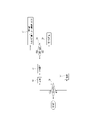
- FIG. 1 is a perspective view of the electric prosthetic leg according to the first embodiment of the present invention as seen obliquely from the front;
- FIG. FIG. 2 is a perspective view of the electric prosthesis of FIG. 1 as seen obliquely from behind;
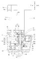
- FIG. 2 is a diagram showing the internal structure of the electric prosthetic leg of FIG. 1;
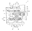
- 2 is an enlarged view of the power transmission part of the electric prosthetic leg of FIG. 1;
- FIG. FIG. 5 is a diagram showing power transmission of the power transmission unit of FIG. 4 when the power transmission unit is in the first speed change state;
- FIG. 5 is a diagram showing power transmission of the power transmission unit when the power transmission unit of FIG. 4 is in a second speed change state;
- FIG. 5 is a diagram showing power transmission of the power transmission unit when the power transmission unit of FIG. 4 is in a free state
- FIG. 10 is a diagram illustrating extension from a bent state of the knee joint mechanism when climbing stairs.
- FIG. 10 is a diagram illustrating bending from the extended state of the knee joint mechanism when climbing stairs
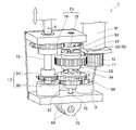
- FIG. 8 is a perspective view of the power transmission part of the electric prosthetic leg according to the second embodiment of the present invention
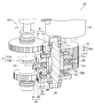
- FIG. 9 is a cross-sectional view of the power transmission portion of FIG. 8
- FIG. 3 is a functional block diagram of a control system in step-up control of the first example; It is a figure explaining the sensor etc. of an electric prosthetic leg which are required for the step-up control of a 1st example.
- FIG. 3 is a functional block diagram of a control system in step-up control of the first example; It is a figure explaining the sensor etc. of an electric prosthetic leg which are required for the step-up control of a 1st example.
- FIG. 10 is a diagram showing a flow when the electric prosthetic leg is on the stance side in the step-up control of the first example;
- FIG. 10 is a diagram showing a flow when the electric prosthetic leg is on the free leg side in the step-up control of the first example; It is a graph which shows the load and hip-joint torque at the time of raising a stage.
- It is a functional block diagram of the control system in the step-up control of the second example. It is a figure explaining the sensor etc. of an electric prosthetic leg required for the stage-up control of a 2nd example.
- FIG. 10 is a diagram showing a flow when the electric prosthesis is on the stance side in the step-up control of the second example.
- 7 is a graph showing the relationship between knee joint torque and knee angle and motor control in step-up control of the second example. It is a graph which shows the load and hip-joint torque at the time of raising a stage.
- the electric prosthetic leg 1 of this embodiment is a prosthetic leg for people without knees, and as shown in FIGS. function as As shown in FIGS. 1 to 3, the electric prosthesis 1 includes a below-the-knee member 10 positioned below the knee, an above-the-knee member 20 positioned above the knee, the below-the-knee member 10 and the above-the-knee member 20.
- a knee joint mechanism 30 which is articulated so as to change the angle formed between them, and an expansion device 40 which can change the angle formed by the below-the-knee member 10 and the above-the-knee member 20 by expanding and contracting.
- the upper knee member 20 includes an upper wall portion 22 provided with an adapter 21 connected to a socket (not shown), and a pair of upper side wall portions 23 extending downward from both left and right ends of the upper wall portion 22. It has a substantially U shape with an open bottom when viewed from above.
- the below-the-knee side member 10 includes a lower wall portion 12 provided with leg portions 11, and a pair of lower side wall portions 13 extending upward from both left and right ends of the lower wall portion 12.
- the upper side is open when viewed in the front-rear direction. It has a substantially U-shaped shape.
- the pair of lower side wall portions 13 of the below-the-knee member 10 are rotatably connected about the rotating portion 35.
- This mechanism connects the below-the-knee member 10 and the above-the-knee member 20 so that the angle formed by the member 20 can be changed, and the knee joint mechanism 30 is configured.
- an expansion device 40 that can change the angle formed by the above-knee member 10 and the above-knee member 20 is provided.
- the expansion device 40 is connected to a motor M that outputs rotational power, a transmission T that transmits the power of the motor M, and the transmission T so that power can be transmitted.
- a first spindle unit SP1 that converts rotational power into translational motion
- an intermittent mechanism 50 that is interposed between a motor M and a first transmission mechanism T1 and a second transmission mechanism T2 of a transmission T described later
- a second spindle unit SP2 that converts the rotational power output from M into translational motion of the actuator 55 of the intermittent mechanism 50;
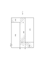
- the transmission T includes a top plate portion 61, a bottom plate portion 62, and a pair of side plate portions 63 connecting left and right ends of the top plate portion 61 and the bottom plate portion 62, and has a rectangular shape when viewed from the front-rear direction.
- a transmission case 60 is provided.
- a pair of rotary wings 64 extending downward from a bottom plate portion 62 of the transmission case 60 can swing around a lower swing portion 70 on a rotation support wall 14 extending upward from the lower wall portion 12 of the below-the-knee side member 10 . and immovably supported.
- the motor M is arranged in front of and above the top plate portion 61 of the transmission case 60 so that the output shaft 71 penetrates the top plate portion 61 and protrudes inside the transmission case 60 .
- the first spindle unit SP1 is arranged on the side opposite to the motor M with the intermittent mechanism 50 interposed therebetween in the front-rear direction. In other words, the motor M is arranged forward of the intermittent mechanism 50 in the longitudinal direction, and the first spindle unit SP1 is arranged rearward of the intermittent mechanism 50 in the longitudinal direction.
- the second spindle unit SP2 which converts the rotational power output from the motor M into translational motion of the actuator 55 of the intermittent mechanism 50, is arranged between the motor M and the first spindle unit SP1 in the front-rear direction.
- the output shaft 71 of the motor M, the first spindle 73 of the first spindle unit SP1, and the second spindle 75 of the second spindle unit SP2 are arranged in parallel with each other, and when the knee joint mechanism 30 is fully extended, it can move vertically. are placed facing the
- the first spindle unit SP1 has a first spindle 73 having a male thread 73a and a sleeve 74 having a female thread 74a. translate along.
- the first spindle 73 receives rotational power of the motor M transmitted by the transmission T and performs rotational motion.
- the sleeve 74 is attached to a pair of inner side wall portions 24 extending downward from the upper wall portion 22 of the upper knee member 20 so as to be able to swing around the upper swing portion 25 and not move. Therefore, when the first spindle 73 rotates to one side (in the direction of arrow D1 in FIG.
- the distance between the sleeve 74 and the transmission T expands and contracts according to the rotation direction of the first spindle 73 . Since the sleeve 74 is immovably attached to the upper-knee member 20 as described above, the distance between the sleeve 74 and the transmission T expands and contracts according to the rotation direction of the first spindle 73, so that the transmission T
- the below-the-knee member 10 to which the sleeve 74 is attached and the above-the-knee member 20 to which the sleeve 74 is attached rotate around the rotating portion 35 . As a result, the angle formed by the upper-knee member 20 and the lower-knee member 10 changes.
- the transmission T is an output gear 72 provided on the output shaft 71 of the motor M, and an input gear 72 provided substantially in the center of the second spindle 75 of the second spindle unit SP2 and meshing with the output gear 72.
- a gear 77, a first transmission mechanism T1, and a second transmission mechanism T2 are provided.
- the first transmission mechanism T1 includes a first drive gear 78 immovably provided above the second spindle 75 of the second spindle unit SP2, and a first spindle 73 of the first spindle unit SP1 integrated with the first spindle 73. It comprises a first driven gear 79 which is rotatably provided and meshes with a first driving gear 78 .
- the second transmission mechanism T2 includes a second driving gear 80 immovably provided under the second spindle 75 of the second spindle unit SP2, and a first spindle 73 on the first spindle 73 of the first spindle unit SP1. It comprises a second driven gear 81 which is provided so as to rotate integrally and meshes with the second driving gear 80 .
- the first transmission mechanism T1 serves as a first power transmission path to transmit the power of the motor M at a first gear ratio.
- the second transmission mechanism T2 serves as a second power transmission path to transmit the power of the motor M at a second gear ratio different from the first gear ratio.
- the first gear ratio and the second gear ratio may be different, and one of the first transmission mechanism T1 and the second transmission mechanism T2 may be a reduction mechanism and the other may be a speed increase mechanism.
- One may be a constant velocity mechanism and the other may be a reduction mechanism or speed increasing mechanism, both may be reduction mechanisms, or both may be speed increasing mechanisms.
- the first gear ratio is a speed change that is the number of revolutions on the opposite side of the motor M (first spindle unit SP1 side) in the first transmission mechanism T1 with respect to the pre-shift number of revolutions that is the number of revolutions on the motor M side in the first transmission mechanism T1.
- the ratio of the post-rotational speed is defined as the ratio of the rotational speed before shifting, which is the rotational speed of the motor M side in the second transmission mechanism T2. ), the first gear ratio is preferably smaller than the second gear ratio.
- the first transmission gear ratio of the first transmission mechanism T1 when the first transmission gear ratio of the first transmission mechanism T1 is smaller than 1, the rotation speed on the opposite side of the motor M (first spindle unit SP1 side) is lower than the rotation speed on the motor M side, and the torque increases.
- the second gear ratio of the second transmission mechanism T2 is greater than 1, the rotation speed on the opposite side of the motor M (first spindle unit SP1 side) increases more than the rotation speed on the motor M side, and the torque decreases.
- the first drive gear 78 has a smaller diameter than the second drive gear 80, and the first drive gear 78 and the motor M can be arranged close to each other.
- the first transmission mechanism T1 is arranged closer to the motor M than the second transmission mechanism T2. More specifically, the motor M is arranged in front of the first drive gear 78 so as to vertically overlap the first drive gear 78 .
- a switching mechanism 50 switches between the first transmission mechanism T1 and the second transmission mechanism T2.
- the connecting/disconnecting mechanism 50 rotates integrally with an upper clutch 50U that switches between disconnection and connection of power in the first transmission mechanism T1, a lower clutch 50D that switches between disconnection and connection of power in the second transmission mechanism T2, and the input gear 77. and an actuator 55 .
- the upper clutch 50U is a dog clutch that includes a first engaging element 51 that is an engaging element on the motor M side and a second engaging element 52 that is an engaging element on the first transmission mechanism T1 side. More specifically, the first engaging element 51 is provided above the operating element 55 and the input gear 77 so as to rotate integrally with the input gear 77 . The second engaging element 52 is provided below the first driving gear 78 so as to be able to engage with the first engaging element 51 so as to rotate together with the first driving gear 78 . The second engaging piece 52 and the first drive gear 78 are mounted above the second spindle 75 of the second spindle unit SP2 so as to be relatively rotatable and immovable with respect to the second spindle 75 .
- the lower clutch 50D is a dog clutch that includes a third engaging element 53 that is an engaging element on the motor M side and a fourth engaging element 54 that is an engaging element on the second transmission mechanism T2 side. More specifically, the third engaging element 53 is provided below the operating element 55 and the input gear 77 so as to rotate integrally with the input gear 77 .
- the fourth engaging element 54 is provided above the second driving gear 80 so as to rotate together with the second driving gear 80 so as to be engageable with the third engaging element 53 .
- the fourth engaging piece 54 and the second drive gear 80 are attached below the second spindle 75 of the second spindle unit SP2 so as to be relatively rotatable and immovable with respect to the second spindle 75 .
- the operating element 55 is attached to the input gear 77 so as to rotate together with the input gear 77 as described above, and the first engaging element 51 and the third engaging element 53 are attached to the upper and lower portions thereof so as to rotate together. ing.
- the actuator 55 is interposed between the first drive gear 78 and the second drive gear 80 in the approximate center of the second spindle 75, that is, in the vertical direction.
- the actuator 55 is the screw nut 76 of the second spindle unit SP2.
- the second spindle unit SP2 has a second spindle 75 with a male thread and a screw nut 76 (actuator 55) with a female thread. The actuator 55) translates while rotating along the axis of the second spindle 75 .
- the disconnecting mechanism 50 can take three states of the first speed change state, the second speed change state, and the free state as the actuator 55 translates along the axis of the second spindle 75 .
- the motor M rotates in the first direction (the direction of arrow D1 in FIG. 5A), and the screw nut 76 (actuator 55) moves upward.
- the coupling element 51 and the second engaging element 52 are in the connected state, and the third engaging element 53 and the fourth engaging element 54 are in the disconnected state.
- the upper clutch 50U is engaged and the lower clutch 50D is disengaged.
- the power of the motor M is the output gear 72, the input gear 77, the operating element 55, the first engaging element 51, the second engaging element 52, the first driving gear 78, the first driven gear 79, the first It is transmitted to the spindle unit SP1.
- the motor M rotates in the second direction (arrow D2 direction in FIG. 5B), and the screw nut 76 (actuator 55) moves downward to move the first engagement.
- the connecting piece 51 and the second engaging piece 52 will be in the disconnected state, and the third engaging piece 53 and the fourth engaging piece 54 will be in the connected state.
- the upper clutch 50U is disengaged and the lower clutch 50D is engaged.
- the power of the motor M is the output gear 72, the input gear 77, the operating element 55, the third engaging element 53, the fourth engaging element 54, the second driving gear 80, the second driven gear 81, the first It is transmitted to the spindle unit SP1.
- the first engaging element 51 and the second engaging element 52 are in the disconnected state, and the third engaging element 53 and the fourth engaging element 54 are in the disconnected state.
- both the upper clutch 50U and the lower clutch 50D are disengaged.
- the motor M stops, and the rotation of the first spindle unit SP1 causes the first driven gear 79 and the second driven gear 81 to rotate. 1 driving gear 78 and the second engaging element 52 , but not the first engaging element 51 .
- the rotation of the first spindle unit SP1 is transmitted to the second driven gear 81, the second drive gear 80, and the fourth engaging element 54, but not to the third engaging element 53.
- reference symbol D denotes a rotary damper
- the screw nut 76 (actuator 55) can be reliably translated.
- the rotary damper D is provided on the second spindle 75 of the second spindle unit SP2 so as to rotate integrally with the first damper gear 86 provided on the rotating shaft of the rotary damper D, and the first damper gear 86. It is composed of a second damper gear 87 and a second damper gear 87 .
- the rotary damper D is arranged in front of and above the bottom plate portion 62 of the transmission case 60 and below the motor M. As shown in FIG.
- the power of the motor M is transmitted from the output gear 72 to the input gear 77 by rotating the motor M in the first direction (arrow D1 direction in FIG. 5A).
- the input gear 77 rotates in the second direction (direction of arrow D2 in FIG. 5A)
- the operating element 55 rotates around the second spindle 75 of the second spindle unit SP2 and is guided upward by the second spindle 75.
- the operating element 55 and the first engaging element 51 provided above the input gear 77 are engaged with the second engaging element 52 provided below the first drive gear 78, and the intermittent mechanism 50 is in the first shift state. becomes.
- the power of the motor M is applied to the output gear 72, the input gear 77, the operating element 55, the first engaging element 51, the second engaging element 52, the first driving gear 78, the first driven gear It is transmitted to the gear 79 and the first spindle unit SP1.
- the first drive gear 78 rotates together with the input gear 77 in the second direction (direction of arrow D2 in FIG. 5A)
- the first driven gear 79 rotates in the first direction (direction of arrow D1 in FIG. 5A).
- the rotation of the driven gear 79 in the first direction (direction of arrow D1 in FIG.
- the power of the motor M is transmitted from the output gear 72 to the input gear 77 by rotating the motor M in the second direction (arrow D2 direction in FIG. 5B).
- the actuator 55 rotates around the second spindle 75 of the second spindle unit SP2 and is guided downward by the second spindle 75.
- the operating element 55 and the third engaging element 53 provided below the input gear 77 are engaged with the fourth engaging element 54 provided above the second drive gear 80, and the intermittent mechanism 50 enters the second shift state. becomes.
- the power of the motor M is applied to the output gear 72, the input gear 77, the operating element 55, the third engaging element 53, the fourth engaging element 54, the second drive gear 80, the second driven gear It is transmitted to the gear 81 and the first spindle unit SP1.
- the second drive gear 80 rotates together with the input gear 77 in the first direction (direction of arrow D1 in FIG. 5B)
- the second driven gear 81 rotates in the second direction (direction of arrow D2 in FIG. 5B).
- the rotation of the driven gear 81 in the second direction (direction of arrow D2 in FIG.
- the intermittent mechanism 50 By setting the intermittent mechanism 50 to the free state during normal walking, the power transmission between the motor M and the transmission T can be cut off, preventing interference with walking.
- the knee joint mechanism 30 can be extended and bent via the transmission T that transmits the power of the motor M.
- Control of the motor M is performed by a control system 100, which will be described later.
- the rotation range of the knee joint mechanism 30 is limited to 180° or less, and when the knee joint mechanism 30 is extended, the angle formed by the lower knee member 10 and the upper knee member 20 is approximately 180°. When 30 is bent, this angle is less than 180°.
- the transmission T has two power transmission paths with different gear ratios, it is possible to switch between the extension and flexion operation speeds and generated power in the knee joint mechanism 30 .
- the knee joint mechanism 30 is flexed and extended when climbing stairs, the required operating speed and generated power are different. .
- the connecting/disconnecting mechanism 50 interposed between the motor M and the transmission T includes an upper clutch 50U interposed between the motor M and the first transmission mechanism T1, and an upper clutch 50U interposed between the motor M and the second transmission mechanism T2. and the lower clutch 50D interposed between the two power transmission paths can be appropriately switched.
- the extension device 40 includes the second spindle unit SP2 that converts the rotational power output from the motor M into the translational motion of the actuator 55, so that one motor M can control the actuator 55 and the knee joint mechanism 30. control of extension and flexion in the Furthermore, since the transmission T can be switched between the first shift state, the second shift state, and the free state by one actuator 55, it is possible to avoid connecting two power transmission paths at the same time. can.
- the angle formed by the below-the-knee member 10 and the above-the-knee member 20 is The area of less than 180° (the area on the rear (calf) side of the line connecting the rotating portion 35 and the lower rocking portion 70 in FIG. 3) is defined as the narrow angle area (the rotating portion 35 and the lower rocking portion 70 in FIG. 3). It is called a region on the rear (calf) side of the line connecting the moving part 70), and the region forming an angle of 180° or more (from the line connecting the rotating part 35 and the lower swinging part 70 in FIG.
- the electric prosthesis 1 of the second embodiment differs from the electric prosthesis 1 of the first embodiment in the configuration of the extension device 40 . More specifically, in the expansion device 40 of the first embodiment, the translational motion of the operator 55 is realized by converting the rotational power output from the motor M by the second spindle unit SP2. On the other hand, in the telescopic device 40 of the second embodiment, the translational motion of the actuator 55 is achieved by the clutch actuator ACT, which is a drive source different from the motor M, and the clutch fork that transmits the power of the clutch actuator ACT to the actuator 55 . 90 and .
- the expansion device 40 of the electric prosthesis 1 of the second embodiment will be explained with reference to FIGS. The same reference numerals are used in the drawings to omit the description, and only the points of difference will be described.
- the expansion device 40 of the second embodiment is connected to a motor M that outputs rotational power, a transmission T that transmits the power of the motor M, and the transmission T so that the power can be transmitted. and is interposed between the first spindle unit SP1 that converts the rotational power output from the transmission T into translational motion, and the motor M and the first transmission mechanism T1 and the second transmission mechanism T2 of the transmission T.
- the clutch actuator ACT is a power source different from the motor M, and performs translational motion along the axial direction (vertical direction) of the support shaft 95, as indicated by the arrow Y1 in FIG.
- One end of the clutch fork 90 is connected to the clutch actuator ACT, and the middle part is supported by the swing shaft 65, thereby swinging the swing shaft 65 as indicated by an arrow Y2 in FIG. It is configured to be swingable at the center.
- the other end of the clutch fork 90 is provided with an arm 92 bifurcated from a branch portion 91 located on the opposite side of the swing shaft 65 from the clutch actuator ACT and extending arcuately in opposite directions.
- a connecting pin 93 is provided at the tip of each arm 92 to fit a slide clutch 56, which will be described later. Therefore, when the clutch actuator ACT performs a translational motion, the clutch fork 90 swings about the swing shaft 65, and the connecting pin 93 of the clutch fork 90 swings up and down.
- the transmission T includes an output gear 72 provided on the output shaft 71 of the motor M, a first input gear 77A and a second input gear 77B provided substantially in the center of the support shaft 95 and meshing with the output gear 72, a first A transmission mechanism T1 and a second transmission mechanism T2 are provided.
- the input gear 77 is composed of the first input gear 77A and the second input gear 77B.
- the first transmission mechanism T1 includes a first driving gear 78 immovably provided above the support shaft 95, and a first spindle 73 of the first spindle unit SP1 so as to rotate integrally with the first spindle 73, It is composed of a first driven gear 79 that meshes with a first drive gear 78 .
- the second transmission mechanism T2 includes a second driving gear 80 immovably provided under the support shaft 95, and a first spindle 73 of the first spindle unit SP1 so as to rotate integrally with the first spindle 73. , and a second driven gear 81 that meshes with the second drive gear 80 .
- the switching mechanism 50 switches between the first transmission mechanism T1 and the second transmission mechanism T2.
- the connecting/disconnecting mechanism 50 includes an upper clutch 50U interposed between the motor M and the first transmission mechanism T1, a lower clutch 50D interposed between the motor M and the second transmission mechanism T2, and an actuator. 55 and .
- the upper clutch 50U is a dog clutch that includes a first engaging element 51 that is an engaging element on the motor M side and a second engaging element 52 that is an engaging element on the first transmission mechanism T1 side. More specifically, the first engaging piece 51 is provided above the first input gear 77A so as to rotate together with the first input gear 77A. The second engaging element 52 is provided below the first driving gear 78 so as to be able to engage with the first engaging element 51 so as to rotate together with the first driving gear 78 . The second engaging piece 52 and the first drive gear 78 are mounted above the support shaft 95 so as to be rotatable relative to the support shaft 95 and immovable.
- the lower clutch 50D is a dog clutch that includes a third engaging element 53 that is an engaging element on the motor M side and a fourth engaging element 54 that is an engaging element on the second transmission mechanism T2 side. More specifically, the third engaging element 53 is provided below the second input gear 77B so as to rotate together with the second input gear 77B. The fourth engaging element 54 is provided above the second driving gear 80 so as to rotate together with the second driving gear 80 so as to be engageable with the third engaging element 53 . The fourth engaging element 54 and the second driving gear 80 are attached below the support shaft 95 so as to be relatively rotatable and immovable with respect to the support shaft 95 .
- the operating element 55 includes an annular slide clutch 56 that is always engaged with the connecting pin 93 of the clutch fork 90, and a bearing 57 that performs translational motion together with the slide clutch 56. It is arranged between the two input gears 77B.
- the slide clutch 56 is provided with a connection hole with which the connection pin 93 of the clutch fork 90 is engaged.
- the bearing 57 rotates integrally with an outer ring 57a non-rotatably supported by the slide clutch 56, a first input gear 77A provided with a first engaging element 51, and a second input gear 77B provided with a third engaging element 53. and a rolling element 57c disposed between the outer ring 57a and the inner ring 57b to allow relative rotation between the outer ring 57a and the inner ring 57b.
- the inner ring 57b together with the first input gear 77A and the second input gear 77B, is supported on the outer peripheral portion of a support flange 96 key-connected to the support shaft 95 so as to be vertically translatable.
- the slide clutch 56 and the bearing 57 move upward along the support shaft 95 when one end of the clutch fork 90 is moved downward by the clutch actuator ACT. As one end moves upward, it moves downward along the support shaft 95 .
- a predetermined gap is provided in the vertical direction between the slide clutch 56 and the outer ring 57a and the first input gear 77A. configured not to interfere.
- a predetermined gap is provided in the vertical direction between the slide clutch 56 and the outer ring 57a and the second input gear 77B. are configured so that they do not interfere.
- the connecting/disconnecting mechanism 50 has three states of a first speed change state, a second speed change state, and a free state as a result of the slide clutch 56 and the bearing 57 (actuator 55) vertically translating along the axis of the support shaft 95. can take
- the slide clutch 56 and the bearing 57 move upward, so that the first engagement element 51 and the second engagement element 52 are connected and the third The engaging element 53 and the fourth engaging element 54 are in the disconnected state.
- the upper clutch 50U is engaged and the lower clutch 50D is disengaged.
- the power of the motor M is the output gear 72, the first input gear 77A (the inner ring 57b and the second input gear 77B), the first engaging element 51, the second engaging element 52, the first drive gear 78, It is transmitted to the first driven gear 79 and the first spindle unit SP1.
- the slide clutch 56 and the bearing 57 move downward, so that the first engagement element 51 and the second engagement element 52 are disengaged and the third The engaging element 53 and the fourth engaging element 54 are in a connected state.
- the power of the motor M is the output gear 72, the second input gear 77B (the inner ring 57b and the first input gear 77A), the third engaging element 53, the fourth engaging element 54, the second driving gear 80, It is transmitted to the second driven gear 81 and the first spindle unit SP1.
- the first engaging element 51 and the second engaging element 52 are in the disconnected state, and the third engaging element 53 and the fourth engaging element 54 are in the disconnected state.
- the upper clutch 50U is disengaged and the lower clutch 50D is disengaged.
- the motor M stops, and the rotation of the first spindle unit SP1 causes the first driven gear 79 and the second driven gear 81 to rotate. 1 driving gear 78 and the second engaging element 52 , but not the first engaging element 51 .
- the rotation of the first spindle unit SP1 is transmitted to the second driven gear 81, the second drive gear 80, and the fourth engaging element 54, but not to the third engaging element 53.
- the knee joint mechanism 30 can be extended and flexed via the transmission T that transmits the power of the motor M, as in the first embodiment.
- the effects described in the electric prosthesis 1 can be obtained.
- the actuator 55 is switched using the clutch actuator ACT, which is a power source different from the motor M for extending and bending the knee joint mechanism 30, so that the actuator 55 can be switched more stably.
- the actuator 55 can be switched.
- stair climbing control using the electric prosthesis 1 of the first embodiment and the second embodiment will be described by taking the electric prosthesis 1 of the second embodiment as an example.
- a leg that is not externally weighted in other words, a leg that does not support weight is referred to as a swing leg
- a leg that is externally weighted in other words, a leg that supports weight is referred to as a swing leg.
- the leg is called the stance leg.
- the electric prosthesis 1 is always weighted by the gravity of the electric prosthesis 1 (self weight), but it should be noted that the weight of the electric prosthesis 1 is not included in the external load.
- the electric prosthesis 1 includes a load/unweight sensor 201 which is a load sensor provided in the lower part of the below-the-knee member 10 (for example, the leg 11), and A shin IMU (Inertial Measurement Unit) 203, which is a posture sensor capable of detecting the angle of the lower-knee member 10 with respect to the ground (ground angle), and a rotation angle sensor that detects the angle formed by the lower-knee member 10 and the upper-knee member 20.
- a knee angle sensor 205 is provided.
- the control system 100 of the electric prosthesis 1 is the angle between the center line CL5 of the lower leg 5 and the center line CL4 of the thigh 4.
- a knee angle calculation unit 103 that acquires the knee angle ⁇ ;
- a hip joint torque calculation unit 104 that calculates the hip joint torque MYh acting on the hip joint 7 by the weight FZ applied to the below-the-knee member 10;
- a thigh angle calculator 106 that calculates the thigh angle ⁇ that is the angle of the thigh 4 with respect to the line LN, a motor controller 108 that controls the motor M, and an intermittent mechanism controller 110 that controls the state of the intermittent mechanism 50.
- the motor controller 108 also serves as the intermittent mechanism controller 110 .
- the load/unload weight acquisition unit 102 acquires the load FZ, which is the axial force applied to the below-the-knee side member 10 from the load/unload sensor 201 .
- the load FZ applied to the below-the-knee member 10 may be a detected value of the load/unloaded weight sensor 201 or a predicted value.
- the positive direction is when the load FZ applied to the below-the-knee member 10 is in the tensile direction.
- the knee angle calculator 103 obtains the knee angle ⁇ by subtracting the angle detected by the knee angle sensor 205 from 180°.
- the knee angle ⁇ is 0° when the center line CL5 of the lower leg 5 and the center line CL4 of the thigh 4 are aligned, and increases in the positive direction as the knee joint mechanism 30 bends.
- the hip joint torque calculator 104 multiplies the weight FZ applied to the below-the-knee member 10 by the distance from the center line CL5 of the crus 5 to the hip joint 7 (the length of the thigh 4) to obtain the hip joint torque MYh.
- the hip joint torque MYh is given by the following equation (1).
- the positive direction of the hip joint torque MYh is the direction in which the hip joint 7 is rotated forward (clockwise in FIG. 11).
- the length L of the thigh 4 is registered in advance in a memory (not shown), and is preferably rewritable according to the user.
- the thigh angle calculator 106 calculates the thigh angle ⁇ based on the output values of the shin IMU 203 and knee angle sensor 205 .
- the thigh angle ⁇ has a positive value when the thigh 4 is behind an imaginary line LN extending vertically through the hip joint 7, and a negative value when the thigh 4 is ahead of the imaginary line LN. becomes.
- the motor control unit 108 controls the driving/stopping of the motor M and the output when the motor M is driven.
- the step-up control will be described later.
- the intermittent mechanism control unit 110 switches the actuator 55 based on the load FZ acquired by the load/unweight acquiring unit 102, thereby switching the intermittent mechanism 50 to the above-described first shift state, second shift state, and free state. switch.
- the disconnecting mechanism control unit 110 When the prosthetic leg 1 transitions from the free leg to the stance leg or when the transition is predicted, the upper clutch 50U of the upper clutch 50U and the lower clutch 50D of the connecting/disconnecting mechanism 50 is switched to the connected state to set the first shift state. As a result, power can be transmitted through the first transmission mechanism T1 having a small gear ratio when the knee joint mechanism 30 is extended from a bent state, and a large amount of power can be transmitted while the electric prosthesis 1 is weighted from the outside. .
- the connecting/disconnecting mechanism control unit 110 detects that the electric prosthetic leg 1 is standing.
- the lower clutch 50D of the upper clutch 50U and the lower clutch 50D of the connecting/disconnecting mechanism 50 is switched to the connected state to set the second shift state.
- power can be transmitted through the second transmission mechanism T2 having a large gear ratio when the knee joint mechanism 30 is bent from the extended state, and the knee joint can be quickly jointed in a state where the electric prosthesis 1 is not externally loaded.
- Mechanism 30 can be flexed.
- control system 100 may include a traveling direction acquisition unit that acquires the traveling direction of the user of the electric prosthetic leg 1 .
- the traveling direction acquisition unit detects an angular velocity directed upward in the vertical direction, such as when ascending stairs or when climbing a slope, from the detection value of the shin IMU 203, the ascending control may be executed, and the ascending control may be executed based on the user's input.
- the control system 100 performs stance/free leg determination processing for determining whether the electric prosthetic leg 1 is in the stance leg or in the free leg state in step-up control (S1). Specifically, the control system 100 performs stance/swing determination based on the weight FZ acquired by the weight/unweight acquisition unit 102 . As described above, when the load FZ applied to the below-the-knee member 10 is in the tensile direction, the positive direction is assumed. Therefore, when the electric prosthesis 1 is free, the load FZ takes a positive value due to the weight of the electric prosthesis 1 itself. From there, when the electric prosthesis 1 lands and is weighted in the compression direction, the weight FZ approaches zero, and takes a negative value as the weight increases further.
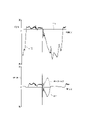
- FIG. 14 is a graph showing the load FZ and the hip joint torque MYh during stair climbing.
- the vertical axis of the upper graph in FIG. MYh (N ⁇ m) is indicated, and the horizontal axes of the upper and lower graphs of FIG. 14 indicate time (s).
- the control system 100 sets the value between 0 (N) and the value when only the weight of the electric prosthesis 1 acts on the electric prosthesis 1 as the threshold T11 (N), and sets the weight FZ to the threshold T11 It is determined whether or not (S1). When the weight FZ is equal to or less than this threshold value T11 (YES in S1), it is determined that the electric prosthesis 1 is standing (S2). On the other hand, when the weight FZ is greater than this threshold value T11 (NO in step S1), it is determined that the electric prosthesis 1 is free (S7). Note that the determination of the stance leg and the free leg may be made based on the user's input. Any means such as a switch, a button, or voice can be used for the user's input.
- the hip joint torque calculator 104 calculates the hip joint torque MYh acting on the hip joint 7 by the weighting FZ (S3).
- hip joint torque is generated to rotate the hip joint 7 backward (counterclockwise in FIG. 11).
- the hip joint torque calculation unit 104 obtains the knee angle ⁇ based on the angle formed by the below-the-knee member 10 and the upper-knee member 20, the length L of the thigh 4, and the weight/unloading obtaining unit 102 from the equation (1).
- a hip joint torque MYh is obtained based on the weighted FZ.
- the motor control unit 108 current-controls the motor M with a torque in the opposite direction equal in magnitude to the hip joint torque MYh as the control target.
- the motor torque and the hip joint torque MYh are balanced and the knee joint mechanism 30 can be extended (S5).
- the control system 100 determines that the thigh angle ⁇ is greater than the threshold ⁇ h1 ( ⁇ h1 is negative) of the thigh angle ⁇ that separates the early swing and the late swing. (S8).
- the thigh angle ⁇ is greater than the threshold value ⁇ h1 (YES in S8), it is determined that the user swings up the thigh 4 and bends the knee joint mechanism 30 (S9).
- the thigh angle ⁇ is 0° or more (S10).
- the current of the motor M is controlled until the thigh angle ⁇ becomes smaller than 0° with the target angle ⁇ k1 (positive value) (S11).
- step S10 If the thigh angle ⁇ is less than 0° in step S10 (NO in S10), the current of the motor M is controlled by setting the value obtained by multiplying the thigh angle ⁇ by -1 and adding ⁇ k1 as the target knee angle as the target knee angle (S12). .
- a in FIG. 13 is a graph showing the target knee angle in steps S11 and S12.
- step S8 when the thigh angle ⁇ is equal to or less than the threshold value ⁇ h1 (NO in S8), and when the knee joint mechanism 30 is bent from step S12 and the thigh angle ⁇ becomes equal to or less than the threshold value ⁇ h1 (YES in S14).
- the free leg late stage that is, the state in which the knee joint mechanism 30 is extended when the user lowers the thigh 4 (S13).
- the target knee angle is obtained by multiplying the thigh angle ⁇ by -1 and adding ⁇ h2, and the current of the motor M is controlled until the thigh angle ⁇ becomes ⁇ h2 or more (S16).
- step S15 when the thigh angle ⁇ is greater than or equal to ⁇ h2 (NO in S15), the target knee angle is set to 0° and the current of the motor M is controlled (S17).
- B in FIG. 13 is a graph showing the target knee angles in steps S16 and S17. It is preferable that the motor control unit 108 performs feedback control based on the knee angle ⁇ obtained by the knee angle calculation unit 103 and the target knee angle in steps S11, S12, S16, and S17.
- the electric prosthesis 1 used for the step-up control of the second example includes a force sensor 207 in place of the weight/unloading sensor 201 described above. That is, the electric prosthesis 1 of the second example includes a shin IMU 203 , a knee angle sensor 205 and a force sensor 207 . As shown in FIG. 16, the force sensor 207 detects at least a load FZ2, which is an axial force applied to the thigh 4, a knee shear force FXk acting in a direction orthogonal to the load FZ2, and a rotation force of the knee joint mechanism 30. A knee torque MYk, which is a turning force around the portion 35, can be detected.
- a load FZ2 which is an axial force applied to the thigh 4
- a knee shear force FXk acting in a direction orthogonal to the load FZ2 and a rotation force of the knee joint mechanism 30.
- a knee torque MYk which is a turning force around the portion 35, can be detected.
- the control system 100 of the electric prosthesis 1 is the angle between the center line CL5 of the lower leg 5 and the center line CL4 of the thigh 4.
- a knee angle calculator 103 that acquires the knee angle ⁇ ;
- a thigh angle calculator 106 that calculates the thigh angle ⁇ , which is the angle of the thigh 4 with respect to the virtual line LN extending vertically through the hip joint 7;
- a thigh weight acquisition unit 112 that acquires the weight FZ2 applied to the thigh 4
- a knee torque acquisition unit 113 that acquires the knee torque MYk
- a knee shear force acquisition unit 114 that acquires the knee shear force FXk applied to the thigh 4.
- a hip joint torque calculation unit 104 that calculates the hip joint torque MYh acting on the hip joint 7 by the knee torque MYk and the knee shear force FXk; a motor control unit 108 that controls the motor M; and a control unit 110 .
- the weight/unweight acquisition unit 102, the knee angle calculation unit 103, the thigh angle calculation unit 106, and the motor control unit 108 are the same as those in the first example, so descriptions thereof will be omitted.
- the thigh weight acquisition unit 112, knee torque acquisition unit 113, and knee shear force acquisition unit 114 acquire the weight FZ2, knee torque MYk, and knee shear force FXk from the force sensor 207, respectively.
- the positive direction is when the load FZ2 applied to the thigh 6 is in the compression direction.
- the hip joint torque calculator 104 adds a value obtained by multiplying the length L of the thigh 4 by the knee shear force FXk to the knee torque MYk to obtain the hip joint torque MYh.
- the hip joint torque MYh is given by the following equation (2).
- the positive direction of the hip joint torque MYh is the direction in which the hip joint 7 is rotated forward (clockwise in FIG. 16).
- connection/disconnection mechanism control unit 110 switches the connection/disconnection mechanism 50 between the above-described first speed change state, second speed change state, and free state based on the load FZ2 acquired by the thigh weight acquisition unit 112 .
- the thigh weight acquisition unit 112 acquires or predicts a transition from a state in which no weight is applied from the outside to a state in which weight is applied from the outside, in other words, when the electric prosthetic leg 1 of the upper clutch 50U and the lower clutch 50D of the connecting/disconnecting mechanism 50 is switched to the connected state to set the first speed change state.
- the electric prosthetic leg 1 of the upper clutch 50U and the lower clutch 50D of the connecting/disconnecting mechanism 50 is switched to the connected state to set the first speed change state.
- power can be transmitted through the first transmission mechanism T1 having a small gear ratio when the knee joint mechanism 30 is extended from a bent state, and a large amount of power can be transmitted while the electric prosthesis 1 is weighted from the outside. .
- the thigh weight acquisition unit 112 acquires or predicts a transition from an externally weighted state to an externally unweighted state, in other words, when the electric prosthesis 1 moves from the stance to the free position.
- the lower clutch 50D of the upper clutch 50U and the lower clutch 50D of the connecting/disconnecting mechanism 50 is switched to the connected state to set the second shift state.
- power can be transmitted through the second transmission mechanism T2 having a large gear ratio when the knee joint mechanism 30 is bent from the extended state, and the knee joint can be quickly jointed in a state where the electric prosthesis 1 is not externally loaded.
- Mechanism 30 can be flexed.
- control system 100 may include a traveling direction acquisition unit that acquires the traveling direction of the user of the electric prosthetic leg 1 .
- the control system 100 performs landing determination to determine whether or not the electric prosthetic leg 1 has landed in the step-up control (S21). Specifically, the control system 100 performs landing determination based on the weight FZ2 acquired by the thigh weight acquisition unit 112 .
- the weight FZ2 takes a positive value due to the self weight of the electric prosthesis 1 (component of the weight FZ). From there, when the electric prosthesis 1 lands and is weighted in the compression direction, the weight FZ2 approaches zero, and takes a negative value as the weight increases further.
- FIG. 19 is a graph showing the load FZ2 and the hip joint torque MYh during stair climbing.
- the vertical axis of the upper graph in FIG. MYh (N ⁇ m) is indicated, and the horizontal axes of the upper and lower graphs of FIG. 19 indicate time (s).
- control system 100 determines that when ⁇ T12 ⁇ FZ2 ⁇ T12 as a region in which the behavior of weight FZ2 is unstable across 0 (N), electric prosthesis 1 is both stance and swing.
- the motor M is stopped without judging (S22).
- the weight FZ2 is greater than or equal to the upper threshold value T12, it is determined that the electric prosthetic leg 1 is free (S23). Note that the control flow when the electric prosthetic leg 1 is in the free leg is the same as in the first example, so the description is omitted here.
- the landing determination may be determined based on the user's input.
- the hip joint torque calculator 104 calculates the hip joint torque MYh acting on the hip joint 7 from the knee torque MYk and the knee shear force FXk (S25).
- the hip joint torque calculator 104 obtains the hip joint torque MYh based on addition of the knee shear force FXk, the length L of the thigh 4, and the knee torque MYk from Equation (2).
- the motor control unit 108 calculates the motor voltage (S26).
- the motor voltage is acquired from a formula based on the hip joint torque MYh, a map showing the relationship between the hip joint torque MYh and the motor voltage, or the like. That is, the motor control unit 108 sets the motor voltage based on the hip joint torque calculated by the hip joint torque calculation unit 104 and controls the motor torque generated from the motor M, thereby appropriately setting the motor torque for extension. can do.
- the knee angle ⁇ is equal to or greater than the threshold ⁇ k2. If there is (S28, area AR1 in FIG. 18), the motor voltage calculated in step S26 is applied (S29). As a result, the motor torque and the hip joint torque MYh are balanced and the knee joint mechanism 30 can be extended.
- the threshold ⁇ k2 is a critical value for avoiding contact between mechanical elements inside the expansion device 40 .
- the hip joint torque MYh is smaller than the threshold -M1 (S27), that is, when the torque acts in a direction to rotate the hip joint 7 backward (counterclockwise in FIG. 16), the knee angle ⁇ is less than the threshold ⁇ k2. If there is (S30, area AR3 in FIG. 18), the motor M is stopped (S31). This makes it possible to avoid contact between mechanical elements inside the expansion device 40 .
- the knee angle ⁇ reaches the threshold ⁇ k3 ( ⁇ k3> ⁇ k2 ), (S32, area AR2 in FIG. 18), the motor voltage calculated in step S26 is applied (S33).
- the threshold ⁇ k3 is a critical value for avoiding contact between mechanical elements inside the expansion device 40, and is a critical value in the opposite direction to that of step 30.
- the electric prosthesis 1 when the behavior of the weight FZ2 is in an unstable region, the electric prosthesis 1 does not determine whether the leg is standing or swinging, and the motor M is stopped (S22), and the hip joint torque MYh is in an unstable region, the knee joint mechanism 30 is neither extended nor flexed and the motor M is stopped (S37).
- an electric prosthetic leg was illustrated as one embodiment of the joint device of the present invention, but the present invention is not limited to this, and may be applied to an upper limb (arm joint), and the wearer may be a person other than a human. It may be an animal or a robot.
- the power of one motor M is transmitted to the first transmission mechanism T1 and the second transmission mechanism T2 via the intermittent mechanism 50.
- Disconnecting mechanisms may be provided between the source and the first transmission mechanism T1 and the second transmission mechanism T2, respectively.
- both the first transmission mechanism T1 and the second transmission mechanism T2 do not necessarily have to be provided, and only one of them may be provided.
- connecting/disconnecting mechanism 50 is not limited to a dog clutch, and may be other clutch mechanisms such as a friction clutch or a centrifugal clutch, or may be a clutchless mechanism such as a continuous gear ratio switching mechanism.
- a joint device comprising an expansion device (expansion device 40) capable of changing the angle formed by the first member and the second member by expanding and contracting,
- the expansion device is a power source (motor M);
- a power transmission unit (transmission T) that transmits power of the power source,
- the power transmission unit is a first power transmission path (first transmission mechanism T1) that transmits the power at a first gear ratio; a second power transmission path (second transmission mechanism T2) that transmits the power at a second gear ratio different from the first gear ratio;
- the expansion device is a first connecting/disconnecting mechanism (upper clutch 50U) for switching disconnection and connection of power in the first power transmission path; a second connecting/disconnecting mechanism (lower clutch 50D) that switches disconnection and connection of power in the second power transmission path;
- the connecting portion can be extended and bent via the power transmission portion that transmits the power of the power source.
- the power transmission section has two power transmission paths with different gear ratios, it is possible to switch the operation speed and generated power for extension and bending at the connecting section.
- the two power transmission paths can be appropriately switched by the first intermittent mechanism and the second intermittent mechanism.
- the connecting portion can be extended or bent by the power from the drive source.
- the connecting portion can be smoothly extended or bent.
- the joint device according to (1) or (2), a control unit (a motor control unit 108 and an intermittent mechanism control unit 110) that controls the power source and the first intermittent mechanism and the second intermittent mechanism; a traveling direction acquisition unit that acquires a traveling direction of the mounting subject of the joint device, The joint device, wherein the control section controls at least one of the first connecting/disconnecting mechanism and the second connecting/disconnecting mechanism based on the traveling direction acquired by the traveling direction acquiring section.
- a control unit a motor control unit 108 and an intermittent mechanism control unit 110
- the joint device is the ratio of the post-shift rotation speed to the pre-shift rotation speed, which is the rotation speed on the power source side in the first power transmission path
- the second gear ratio is the ratio of the post-shift rotation speed to the pre-shift rotation speed, which is the rotation speed on the power source side in the second power transmission path
- the first gear ratio is configured to be smaller than the second gear ratio
- the joint device according to (4), The second member is configured to be attachable to the first portion of the first portion (thigh portion 4) of the attachment subject and the second portion (upper body 3) that rotates relative to the first portion,
- the joint device further includes a rotational force acquisition unit (hip joint torque calculation unit 104) that acquires a rotational force (hip joint torque MYh) of the first portion with respect to the second portion.
- the turning force can be obtained easily and accurately.
- the rotational force acquisition unit is a joint device that acquires the rotational force based on the length of the first portion (the length L of the thigh 4).
- the turning force can be obtained easily and accurately.
- the joint device according to any one of (5) to (7), further comprising a weight acquisition unit (weight/removal weight acquisition unit 102) that acquires the load (weight FZ) applied to the first member, The joint device, wherein the rotational force acquisition section acquires the rotational force based on the weight acquired by the weight acquisition section.
- a weight acquisition unit weight/removal weight acquisition unit 102 that acquires the load (weight FZ) applied to the first member
- the joint device wherein the rotational force acquisition section acquires the rotational force based on the weight acquired by the weight acquisition section.
- the turning force can be obtained easily and accurately.
- the joint device according to any one of (5) to (8), Further comprising a control unit (motor control unit 108, intermittent mechanism control unit 110) that controls the power source, the first intermittent mechanism and the second intermittent mechanism, The joint device, wherein the control section controls the amount of power generated from the power source based on the rotational force acquired by the rotational force acquisition section.
- a control unit motor control unit 108, intermittent mechanism control unit 110
- the control section controls the amount of power generated from the power source based on the rotational force acquired by the rotational force acquisition section.
- a joint device (electric prosthesis 1) comprising an expansion device (expansion device 40) capable of changing the angle formed by the first member and the second member by expanding and contracting,
- the expansion device is a power source (motor M);
- the second member is configured to be attachable to the first portion of the first portion (thigh portion 4), which is the attachment subject of the joint device, and the second portion (upper body 3) that rotates relative to the first portion.
- the joint device is a control unit (motor control unit 108) that controls the power source; a rotational force acquisition unit (hip joint torque calculation unit 104) that acquires the rotational force (hip joint torque MYh) of the first portion with respect to the second portion; The joint device, wherein the control section controls the amount of power generated from the power source based on the rotational force acquired by the rotational force acquisition section.
- a joint device comprising an expansion device (expansion device 40) capable of changing the angle formed by the first member and the second member by expanding and contracting,
- the expansion device is a power source (motor M);
- a power transmission unit (transmission T) that transmits power of the power source,
- the power transmission unit is a first power transmission path (first transmission mechanism T1) that transmits the power at a first gear ratio; a second power transmission path (second transmission mechanism T2) that transmits the power at a second gear ratio different from the first gear ratio;
- the expansion device is a first connecting/disconnecting mechanism (upper clutch 50U) for switching disconnection and connection of power in the first power transmission path; a second connecting/disconnecting mechanism (lower clutch 50D) that switches disconnection and connection of power in the second power transmission path
Abstract
Description
第1部材と、
第2部材と、
前記第1部材と前記第2部材との成す角を変更可能に連接する連接部と、
伸縮することにより前記第1部材と前記第2部材との前記成す角を変更可能な伸縮装置と、を備える継手装置であって、
前記伸縮装置は、
動力源と、
前記動力源の動力を伝達する動力伝達部と、を備え、
前記動力伝達部は、
前記動力を第1変速比で伝達する第1動力伝達路と、
前記動力を前記第1変速比とは異なる第2変速比で伝達する第2動力伝達路と、を備え、
前記伸縮装置は、
前記第1動力伝達路における動力の遮断及び接続を切り替える第1断続機構と、
前記第2動力伝達路における動力の遮断及び接続を切り替える第2断続機構と、を備え、
前記継手装置は、
前記動力源並びに前記第1断続機構及び前記第2断続機構を制御する制御部と、
前記継手装置に加わる加重を取得する加重取得部と、をさらに備え、
前記制御部は、前記加重取得部が取得した前記加重に基づいて、前記第1断続機構及び前記第2断続機構の少なくとも一方を制御する。 The first invention is
a first member;
a second member;
a connecting portion that connects the first member and the second member so as to change the angle formed by the first member;
a joint device that can change the angle formed by the first member and the second member by expanding and contracting,
The expansion device is
power source;
a power transmission unit that transmits the power of the power source,
The power transmission unit is
a first power transmission path that transmits the power at a first gear ratio;
a second power transmission path that transmits the power at a second gear ratio different from the first gear ratio;
The expansion device is
a first disconnecting mechanism that switches between disconnection and connection of power in the first power transmission path;
a second disconnecting mechanism for switching between disconnection and connection of power in the second power transmission path;
The joint device is
a control unit that controls the power source, the first intermittent mechanism, and the second intermittent mechanism;
a weight acquiring unit that acquires the load applied to the joint device,
The control unit controls at least one of the first connecting/disconnecting mechanism and the second connecting/disconnecting mechanism based on the weight acquired by the weight acquiring unit.
第1部材と、
第2部材と、
前記第1部材と前記第2部材との成す角を変更可能に連接する連接部と、
伸縮することにより前記第1部材と前記第2部材との前記成す角を変更可能な伸縮装置と、を備える継手装置であって、
前記伸縮装置は、
動力源と、
前記動力源の動力を伝達する動力伝達部と、を備え、
前記第2部材は、前記継手装置の装着主体の第1部分と該第1部分と相対回動する第2部分のうち前記第1部分に装着可能に構成され、
前記継手装置は、
前記動力源を制御する制御部と、
前記第2部分に対する前記第1部分の回動力を取得する回動力取得部と、をさらに備え、
前記制御部は、前記回動力取得部が取得した前記回動力に基づいて、前記動力源から発生させる動力量を制御する。 The second invention is
a first member;
a second member;
a connecting portion that connects the first member and the second member so as to change the angle formed by the first member;
a joint device that can change the angle formed by the first member and the second member by expanding and contracting,
The expansion device is
power source;
a power transmission unit that transmits the power of the power source,
The second member is configured to be attachable to the first portion of the first portion of the attachment subject of the joint device and the second portion that rotates relative to the first portion,
The joint device is
a control unit that controls the power source;
a turning force acquisition unit that acquires a turning force of the first portion with respect to the second portion;
The control section controls the amount of power generated from the power source based on the rotational force acquired by the rotational force acquisition section.
第1部材と、
第2部材と、
前記第1部材と前記第2部材との成す角を変更可能に連接する連接部と、
伸縮することにより前記第1部材と前記第2部材との前記成す角を変更可能な伸縮装置と、を備える継手装置であって、
前記伸縮装置は、
動力源と、
前記動力源の動力を伝達する動力伝達部と、を備え、
前記動力伝達部は、
前記動力を第1変速比で伝達する第1動力伝達路と、
前記動力を前記第1変速比とは異なる第2変速比で伝達する第2動力伝達路と、
を備え、
前記伸縮装置は、
前記第1動力伝達路における動力の遮断及び接続を切り替える第1断続機構と、
前記第2動力伝達路における動力の遮断及び接続を切り替える第2断続機構と、を備え、
前記継手装置は、
前記動力源並びに前記第1断続機構及び前記第2断続機構を制御する制御部と、
前記継手装置の装着主体の進行方向を取得する進行方向取得部と、をさらに備え、
前記制御部は、前記進行方向取得部が取得した前記進行方向に基づいて、前記第1断続機構及び前記第2断続機構の少なくとも一方を制御する。 The third invention is
a first member;
a second member;
a connecting portion that connects the first member and the second member so as to change the angle formed by the first member;
a joint device that can change the angle formed by the first member and the second member by expanding and contracting,
The expansion device is
power source;
a power transmission unit that transmits the power of the power source,
The power transmission unit is
a first power transmission path that transmits the power at a first gear ratio;
a second power transmission path that transmits the power at a second gear ratio different from the first gear ratio;
with
The expansion device is
a first disconnecting mechanism that switches between disconnection and connection of power in the first power transmission path;
a second disconnecting mechanism for switching between disconnection and connection of power in the second power transmission path;
The joint device is
a control unit that controls the power source, the first intermittent mechanism, and the second intermittent mechanism;
a traveling direction acquisition unit that acquires a traveling direction of the mounting subject of the joint device,
The control unit controls at least one of the first connecting/disconnecting mechanism and the second connecting/disconnecting mechanism based on the traveling direction acquired by the traveling direction acquisition unit.
本実施形態の電動義足1は、ひざのない人のための義足であり、図6及び図7に示すように上半身3と相対回動する一方の大腿部4に装着され、下腿部5として機能する。電動義足1は、図1~図3に示すように、ひざの下側に位置する膝下側部材10と、ひざの上側に位置する膝上側部材20と、膝下側部材10と膝上側部材20との成す角を変更可能に連接する膝関節機構30と、伸縮することにより膝下側部材10と膝上側部材20との成す角を変更可能な伸縮装置40と、を備える。 <First embodiment> [Electric prosthesis]
The electric
第2実施形態の電動義足1は、伸縮装置40の構成が第1実施形態の電動義足1と異なるものである。より具体的に説明すると、第1実施形態の伸縮装置40では、作動子55の並進運動は、モータMから出力される回転動力が第2スピンドルユニットSP2によって変換されることで実現された。これに対し、第2実施形態の伸縮装置40では、作動子55の並進運動は、モータMとは異なる駆動源であるクラッチアクチュエータACTと、クラッチアクチュエータACTの動力を作動子55に伝達するクラッチフォーク90と、により実現される。以下の説明では、第2実施形態の電動義足1の伸縮装置40について図8及び図9を参照しながら説明するが、第1実施形態の電動義足1の伸縮装置40と同一又は同等の構成について図中に同一の符号を付して説明を省略し、相違点についてのみ説明する。 <Second embodiment>
The
続いて、上記した第1実施形態及び第2実施形態の電動義足1を用いた階段の昇段制御について、第2実施形態の電動義足1を例に説明する。なお、以下の説明では、外部から加重がされていない脚、言い換えると体重を支えていない状態の脚を遊脚と称し、外部から加重がされている脚、言い換えると体重を支えている状態の脚を立脚と称する。なお、電動義足1には、常に電動義足1の重力による重さ(自重)が作用しているが、自重は外部からの加重に含まれない点に留意されたい。 <Upgrade control>
Subsequently, stair climbing control using the
図10及び図11に示すように、電動義足1には、膝下側部材10の下部(例えば、脚部11)に設けられた荷重センサである加重/抜重センサ201と、膝下側部材10に設けられ膝下側部材10の地面に対する角度(対地角)を検出可能な姿勢センサである脛IMU(Inertial Measurement Unit)203と、膝下側部材10と膝上側部材20との成す角を検出する回転角センサである膝角度センサ205と、が設けられる。 [First example]
As shown in FIGS. 10 and 11 , the
制御システム100は、図12に示すように、昇段制御において、電動義足1が立脚であるか遊脚であるかを判定する立脚/遊脚判定処理を行う(S1)。具体的に説明すると、制御システム100は、加重/抜重取得部102が取得した加重FZに基づいて立脚/遊脚判定を行う。上記したように、膝下側部材10に加わる加重FZが引張方向のときを正方向とするので、電動義足1が遊脚であるとき、電動義足1の自重により加重FZは正の値をとる。そこから、電動義足1が着地して圧縮方向に加重されると、加重FZは、零に近づき、さらに加重が増加すると負の値をとる。 The control flow of the step-up control of the first example will be described below.
As shown in FIG. 12, the
図15及び図16に示すように、第2例の昇段制御に使用される電動義足1は、前述した加重/抜重センサ201に代えて力覚センサ207を備える。即ち、第2例の電動義足1は、脛IMU203、膝角度センサ205、及び力覚センサ207を備える。力覚センサ207は、図16に示すように、少なくとも、大腿部4に加わる軸力である加重FZ2、加重FZ2に直交する方向に作用する膝せん断力FXk、及び膝関節機構30の回動部35回りの回動力である膝トルクMYkを検出可能に構成される。 [Second example]
As shown in FIGS. 15 and 16, the
制御システム100は、図17に示すように、昇段制御において、電動義足1が着地したか否かを判定する着地判定を行う(S21)。具体的に説明すると、制御システム100は、大腿部加重取得部112が取得した加重FZ2に基づいて着地判定を行う。電動義足1が遊脚であるとき、電動義足1の自重(加重FZの分力)により加重FZ2は正の値をとる。そこから、電動義足1が着地して圧縮方向に加重されると、加重FZ2は、零に近づき、さらに加重が増加すると負の値をとる。 The control flow of the second example of the control during step-up will be described below.
As shown in FIG. 17, the
第2部材(膝上側部材20)と、
前記第1部材と前記第2部材との成す角を変更可能に連接する連接部(膝関節機構30)と、
伸縮することにより前記第1部材と前記第2部材との前記成す角を変更可能な伸縮装置(伸縮装置40)と、を備える継手装置(電動義足1)であって、
前記伸縮装置は、
動力源(モータM)と、
前記動力源の動力を伝達する動力伝達部(変速機T)と、を備え、
前記動力伝達部は、
前記動力を第1変速比で伝達する第1動力伝達路(第1変速機構T1)と、
前記動力を前記第1変速比とは異なる第2変速比で伝達する第2動力伝達路(第2変速機構T2)と、を備え、
前記伸縮装置は、
前記第1動力伝達路における動力の遮断及び接続を切り替える第1断続機構(上側クラッチ50U)と、
前記第2動力伝達路における動力の遮断及び接続を切り替える第2断続機構(下側クラッチ50D)と、を備え、
前記継手装置は、
前記動力源並びに前記第1断続機構及び前記第2断続機構を制御する制御部(モータ制御部108、断続機構制御部110)と、
前記継手装置に加わる加重(加重FZ、加重FZ2)を取得する加重取得部(加重/抜重取得部102、大腿部加重取得部112)と、をさらに備え、
前記制御部は、前記加重取得部が取得した前記加重に基づいて、前記第1断続機構及び前記第2断続機構の少なくとも一方を制御する、継手装置。 (1) a first member (below-the-knee member 10);
a second member (upper knee member 20);
a connecting portion (knee joint mechanism 30) that connects the first member and the second member so as to change the angle formed;
A joint device (electric prosthesis 1) comprising an expansion device (expansion device 40) capable of changing the angle formed by the first member and the second member by expanding and contracting,
The expansion device is
a power source (motor M);
A power transmission unit (transmission T) that transmits power of the power source,
The power transmission unit is
a first power transmission path (first transmission mechanism T1) that transmits the power at a first gear ratio;
a second power transmission path (second transmission mechanism T2) that transmits the power at a second gear ratio different from the first gear ratio;
The expansion device is
a first connecting/disconnecting mechanism (upper clutch 50U) for switching disconnection and connection of power in the first power transmission path;
a second connecting/disconnecting mechanism (lower clutch 50D) that switches disconnection and connection of power in the second power transmission path;
The joint device is
a control unit (a
a weight acquisition unit (weight/removal
The joint device, wherein the control section controls at least one of the first connecting/disconnecting mechanism and the second connecting/disconnecting mechanism based on the weight acquired by the weight acquiring section.
前記制御部は、前記加重取得部が前記加重がされていない状態から前記加重がされる状態に遷移したことを取得したときに、前記第1断続機構及び前記第2断続機構の何れか一方を接続状態に切り替える、継手装置。 (2) The joint device according to (1),
When the weight acquiring unit acquires that the state in which the weight is not applied has changed to the state in which the weight is applied, the control unit enables either one of the first connecting/disconnecting mechanism and the second connecting/disconnecting mechanism. Coupling device that switches to the connected state.
前記動力源並びに前記第1断続機構及び前記第2断続機構を制御する制御部(モータ制御部108、断続機構制御部110)と、
前記継手装置の装着主体の進行方向を取得する進行方向取得部と、をさらに備え、
前記制御部は、前記進行方向取得部が取得した前記進行方向に基づいて、前記第1断続機構及び前記第2断続機構の少なくとも一方を制御する、継手装置。 (3) The joint device according to (1) or (2),
a control unit (a
a traveling direction acquisition unit that acquires a traveling direction of the mounting subject of the joint device,
The joint device, wherein the control section controls at least one of the first connecting/disconnecting mechanism and the second connecting/disconnecting mechanism based on the traveling direction acquired by the traveling direction acquiring section.
前記第1変速比を、前記第1動力伝達路における前記動力源側の回転数である変速前回転数に対する、変速後回転数の比率とし、
前記第2変速比を、前記第2動力伝達路における前記動力源側の回転数である変速前回転数に対する、変速後回転数の比率としたとき、
前記第1変速比は、前記第2変速比よりも小さくなるよう構成され、
前記制御部は、前記装着主体が鉛直方向上方に進行することを取得したときに、前記第1断続機構を接続状態とする、継手装置。 (4) The joint device according to (3),
The first gear ratio is the ratio of the post-shift rotation speed to the pre-shift rotation speed, which is the rotation speed on the power source side in the first power transmission path,
When the second gear ratio is the ratio of the post-shift rotation speed to the pre-shift rotation speed, which is the rotation speed on the power source side in the second power transmission path,
The first gear ratio is configured to be smaller than the second gear ratio,
The joint device, wherein the control unit puts the first connecting/disconnecting mechanism in a connected state when it acquires that the mounting subject moves upward in a vertical direction.
前記第2部材は、前記装着主体の第1部分(大腿部4)と該第1部分と相対回動する第2部分(上半身3)のうち前記第1部分に装着可能に構成され、
前記継手装置は、前記第2部分に対する前記第1部分の回動力(股関節トルクMYh)を取得する回動力取得部(股関節トルク算出部104)をさらに備える、継手装置。 (5) The joint device according to (4),
The second member is configured to be attachable to the first portion of the first portion (thigh portion 4) of the attachment subject and the second portion (upper body 3) that rotates relative to the first portion,
The joint device further includes a rotational force acquisition unit (hip joint torque calculation unit 104) that acquires a rotational force (hip joint torque MYh) of the first portion with respect to the second portion.
前記回動力取得部は、前記成す角に基づいて前記回動力を取得する、継手装置。 (6) The joint device according to (5),
The joint device, wherein the rotational force acquisition unit acquires the rotational force based on the formed angle.
前記回動力取得部は、前記第1部分の長さ(大腿部4の長さL)に基づいて前記回動力を取得する、継手装置。 (7) The joint device according to (5) or (6),
The rotational force acquisition unit is a joint device that acquires the rotational force based on the length of the first portion (the length L of the thigh 4).
前記第1部材に加わる加重(加重FZ)を取得する加重取得部(加重/抜重取得部102)をさらに備え、
前記回動力取得部は、前記加重取得部が取得した前記加重に基づいて前記回動力を取得する、継手装置。 (8) The joint device according to any one of (5) to (7),
further comprising a weight acquisition unit (weight/removal weight acquisition unit 102) that acquires the load (weight FZ) applied to the first member,
The joint device, wherein the rotational force acquisition section acquires the rotational force based on the weight acquired by the weight acquisition section.
前記動力源並びに前記第1断続機構及び前記第2断続機構を制御する制御部(モータ制御部108、断続機構制御部110)をさらに備え、
前記制御部は、前記回動力取得部が取得した前記回動力に基づいて、前記動力源から発生させる動力量を制御する、継手装置。 (9) The joint device according to any one of (5) to (8),
Further comprising a control unit (
The joint device, wherein the control section controls the amount of power generated from the power source based on the rotational force acquired by the rotational force acquisition section.
第2部材(膝上側部材20)と、
前記第1部材と前記第2部材との成す角を変更可能に連接する連接部(膝関節機構30)と、
伸縮することにより前記第1部材と前記第2部材との前記成す角を変更可能な伸縮装置(伸縮装置40)と、を備える継手装置(電動義足1)であって、
前記伸縮装置は、
動力源(モータM)と、
前記動力源の動力を伝達する動力伝達部(変速機T)と、を備え、
前記第2部材は、前記継手装置の装着主体の第1部分(大腿部4)と該第1部分と相対回動する第2部分(上半身3)のうち前記第1部分に装着可能に構成され、
前記継手装置は、
前記動力源を制御する制御部(モータ制御部108)と、
前記第2部分に対する前記第1部分の回動力(股関節トルクMYh)を取得する回動力取得部(股関節トルク算出部104)と、をさらに備え、
前記制御部は、前記回動力取得部が取得した前記回動力に基づいて、前記動力源から発生させる動力量を制御する、継手装置。 (10) a first member (below-the-knee member 10);
a second member (upper knee member 20);
a connecting portion (knee joint mechanism 30) that connects the first member and the second member so as to change the angle formed;
A joint device (electric prosthesis 1) comprising an expansion device (expansion device 40) capable of changing the angle formed by the first member and the second member by expanding and contracting,
The expansion device is
a power source (motor M);
A power transmission unit (transmission T) that transmits power of the power source,
The second member is configured to be attachable to the first portion of the first portion (thigh portion 4), which is the attachment subject of the joint device, and the second portion (upper body 3) that rotates relative to the first portion. is,
The joint device is
a control unit (motor control unit 108) that controls the power source;
a rotational force acquisition unit (hip joint torque calculation unit 104) that acquires the rotational force (hip joint torque MYh) of the first portion with respect to the second portion;
The joint device, wherein the control section controls the amount of power generated from the power source based on the rotational force acquired by the rotational force acquisition section.
第2部材(膝上側部材20)と、
前記第1部材と前記第2部材との成す角を変更可能に連接する連接部(膝関節機構30)と、
伸縮することにより前記第1部材と前記第2部材との前記成す角を変更可能な伸縮装置(伸縮装置40)と、を備える継手装置(電動義足1)であって、
前記伸縮装置は、
動力源(モータM)と、
前記動力源の動力を伝達する動力伝達部(変速機T)と、を備え、
前記動力伝達部は、
前記動力を第1変速比で伝達する第1動力伝達路(第1変速機構T1)と、
前記動力を前記第1変速比とは異なる第2変速比で伝達する第2動力伝達路(第2変速機構T2)と、を備え、
前記伸縮装置は、
前記第1動力伝達路における動力の遮断及び接続を切り替える第1断続機構(上側クラッチ50U)と、
前記第2動力伝達路における動力の遮断及び接続を切り替える第2断続機構(下側クラッチ50D)と、を備え、
前記継手装置は、
前記動力源並びに前記第1断続機構及び前記第2断続機構を制御する制御部(モータ制御部108、断続機構制御部110)と、
前記継手装置の装着主体の進行方向を取得する進行方向取得部と、をさらに備え、
前記制御部は、前記進行方向取得部が取得した前記進行方向に基づいて、前記第1断続機構及び前記第2断続機構の少なくとも一方を制御する、継手装置。 (11) a first member (below-the-knee member 10);
a second member (upper knee member 20);
a connecting portion (knee joint mechanism 30) that connects the first member and the second member so as to change the angle formed;
A joint device (electric prosthesis 1) comprising an expansion device (expansion device 40) capable of changing the angle formed by the first member and the second member by expanding and contracting,
The expansion device is
a power source (motor M);
A power transmission unit (transmission T) that transmits power of the power source,
The power transmission unit is
a first power transmission path (first transmission mechanism T1) that transmits the power at a first gear ratio;
a second power transmission path (second transmission mechanism T2) that transmits the power at a second gear ratio different from the first gear ratio;
The expansion device is
a first connecting/disconnecting mechanism (upper clutch 50U) for switching disconnection and connection of power in the first power transmission path;
a second connecting/disconnecting mechanism (lower clutch 50D) that switches disconnection and connection of power in the second power transmission path;
The joint device is
a control unit (a
a traveling direction acquisition unit that acquires a traveling direction of the mounting subject of the joint device,
The joint device, wherein the control section controls at least one of the first connecting/disconnecting mechanism and the second connecting/disconnecting mechanism based on the traveling direction acquired by the traveling direction acquiring section.
3 上半身(第2部分)
4 大腿部(第1部分)
10 膝下側部材(第1部材)
20 膝上側部材(第2部材)
30 膝関節機構(連接部)
40 伸縮装置
50D 下側クラッチ(第2断続機構)
50U 上側クラッチ(第1断続機構)
102 加重/抜重取得部(加重取得部)
104 股関節トルク算出部(回動力取得部)
108 モータ制御部(制御部)
110 断続機構制御部(制御部)
112 大腿部加重取得部(加重取得部)
M モータ(動力源)
T 変速機(動力伝達部)
T1 第1変速機構(第1動力伝達路)
T2 第2変速機構(第2動力伝達路)
1 Electric prosthesis (joint device)
3 upper body (second part)
4 thigh (first part)
10 Lower knee side member (first member)
20 Upper knee member (second member)
30 Knee joint mechanism (articulation part)
40
50U upper clutch (first disconnecting mechanism)
102 weighted/unweighted acquisition unit (weighted acquisition unit)
104 Hip joint torque calculation unit (rotational force acquisition unit)
108 motor control unit (control unit)
110 intermittent mechanism control unit (control unit)
112 thigh weight acquisition unit (weight acquisition unit)
M motor (power source)
T transmission (power transmission part)
T1 first transmission mechanism (first power transmission path)
T2 second transmission mechanism (second power transmission path)
Claims (11)
- 第1部材と、
第2部材と、
前記第1部材と前記第2部材との成す角を変更可能に連接する連接部と、
伸縮することにより前記第1部材と前記第2部材との前記成す角を変更可能な伸縮装置と、を備える継手装置であって、
前記伸縮装置は、
動力源と、
前記動力源の動力を伝達する動力伝達部と、を備え、
前記動力伝達部は、
前記動力を第1変速比で伝達する第1動力伝達路と、
前記動力を前記第1変速比とは異なる第2変速比で伝達する第2動力伝達路と、
を備え、
前記伸縮装置は、
前記第1動力伝達路における動力の遮断及び接続を切り替える第1断続機構と、
前記第2動力伝達路における動力の遮断及び接続を切り替える第2断続機構と、を備え、
前記継手装置は、
前記動力源並びに前記第1断続機構及び前記第2断続機構を制御する制御部と、
前記継手装置に加わる加重を取得する加重取得部と、をさらに備え、
前記制御部は、前記加重取得部が取得した前記加重に基づいて、前記第1断続機構及び前記第2断続機構の少なくとも一方を制御する、継手装置。 a first member;
a second member;
a connecting portion that connects the first member and the second member so as to change the angle formed by the first member;
a joint device that can change the angle formed by the first member and the second member by expanding and contracting,
The expansion device is
power source;
a power transmission unit that transmits the power of the power source,
The power transmission unit is
a first power transmission path that transmits the power at a first gear ratio;
a second power transmission path that transmits the power at a second gear ratio different from the first gear ratio;
with
The expansion device is
a first disconnecting mechanism that switches between disconnection and connection of power in the first power transmission path;
a second disconnecting mechanism that switches between disconnection and connection of power in the second power transmission path;
The joint device is
a control unit that controls the power source, the first intermittent mechanism, and the second intermittent mechanism;
a weight acquiring unit that acquires the load applied to the joint device,
The joint device, wherein the control section controls at least one of the first connecting/disconnecting mechanism and the second connecting/disconnecting mechanism based on the weight acquired by the weight acquiring section. - 請求項1に記載の継手装置であって、
前記制御部は、前記加重取得部が外部から前記加重がされていない状態から外部から前記加重がされる状態に遷移したことを取得したときに、前記第1断続機構及び前記第2断続機構の何れか一方を接続状態に切り替える、継手装置。 The coupling device according to claim 1,
When the weight acquiring unit acquires that the state in which the weight is not applied from the outside to the state in which the weight is applied from the outside, A coupling device that switches either one to a connected state. - 請求項1又は2に記載の継手装置であって、
前記動力源並びに前記第1断続機構及び前記第2断続機構を制御する制御部と、
前記継手装置の装着主体の進行方向を取得する進行方向取得部と、をさらに備え、
前記制御部は、前記進行方向取得部が取得した前記進行方向に基づいて、前記第1断続機構及び前記第2断続機構の少なくとも一方を制御する、継手装置。 The joint device according to claim 1 or 2,
a control unit that controls the power source, the first intermittent mechanism, and the second intermittent mechanism;
a traveling direction acquisition unit that acquires a traveling direction of the mounting subject of the joint device,
The joint device, wherein the control section controls at least one of the first connecting/disconnecting mechanism and the second connecting/disconnecting mechanism based on the traveling direction acquired by the traveling direction acquiring section. - 請求項3に記載の継手装置であって、
前記第1変速比を、前記第1動力伝達路における前記動力源側の回転数である変速前回転数に対する、変速後回転数の比率とし、
前記第2変速比を、前記第2動力伝達路における前記動力源側の回転数である変速前回転数に対する、変速後回転数の比率としたとき、
前記第1変速比は、前記第2変速比よりも小さくなるよう構成され、
前記制御部は、前記装着主体が鉛直方向上方に進行することを取得したときに、前記第1断続機構を接続状態とする、継手装置。 A coupling device according to claim 3,
The first gear ratio is the ratio of the post-shift rotation speed to the pre-shift rotation speed, which is the rotation speed on the power source side in the first power transmission path,
When the second gear ratio is the ratio of the post-shift rotation speed to the pre-shift rotation speed, which is the rotation speed on the power source side in the second power transmission path,
The first gear ratio is configured to be smaller than the second gear ratio,
The joint device, wherein the control unit puts the first connecting/disconnecting mechanism in a connected state when it acquires that the mounting subject moves upward in a vertical direction. - 請求項4に記載の継手装置であって、
前記第2部材は、前記装着主体の第1部分と該第1部分と相対回動する第2部分のうち前記第1部分に装着可能に構成され、
前記継手装置は、前記第2部分に対する前記第1部分の回動力を取得する回動力取得部をさらに備える、継手装置。 A coupling device according to claim 4,
The second member is configured to be attachable to the first portion of the first portion of the attachment subject and the second portion that rotates relative to the first portion,
The joint device further includes a rotational force acquiring section that acquires a rotational force of the first portion with respect to the second portion. - 請求項5に記載の継手装置であって、
前記回動力取得部は、前記成す角に基づいて前記回動力を取得する、継手装置。 A coupling device according to claim 5,
The joint device, wherein the rotational force acquisition unit acquires the rotational force based on the formed angle. - 請求項5又は6に記載の継手装置であって、
前記回動力取得部は、前記第1部分の長さに基づいて前記回動力を取得する、継手装置。 A joint device according to claim 5 or 6,
The rotational force acquisition unit is a joint device that acquires the rotational force based on the length of the first portion. - 請求項5~7のいずれか一項に記載の継手装置であって、
前記第1部材に加わる加重を取得する加重取得部をさらに備え、
前記回動力取得部は、前記加重取得部が取得した前記加重に基づいて前記回動力を取得する、継手装置。 The joint device according to any one of claims 5 to 7,
further comprising a weight acquisition unit that acquires a load applied to the first member;
The joint device, wherein the rotational force acquisition section acquires the rotational force based on the weight acquired by the weight acquisition section. - 請求項5~8のいずれか一項に記載の継手装置であって、
前記動力源並びに前記第1断続機構及び前記第2断続機構を制御する制御部をさらに備え、
前記制御部は、前記回動力取得部が取得した前記回動力に基づいて、前記動力源から発生させる動力量を制御する、継手装置。 The joint device according to any one of claims 5 to 8,
Further comprising a control unit that controls the power source, the first intermittent mechanism and the second intermittent mechanism,
The joint device, wherein the control section controls the amount of power generated from the power source based on the rotational force acquired by the rotational force acquisition section. - 第1部材と、
第2部材と、
前記第1部材と前記第2部材との成す角を変更可能に連接する連接部と、
伸縮することにより前記第1部材と前記第2部材との前記成す角を変更可能な伸縮装置と、を備える継手装置であって、
前記伸縮装置は、
動力源と、
前記動力源の動力を伝達する動力伝達部と、を備え、
前記第2部材は、前記継手装置の装着主体の第1部分と該第1部分と相対回動する第2部分のうち前記第1部分に装着可能に構成され、
前記継手装置は、前記動力源を制御する制御部と、
前記第2部分に対する前記第1部分の回動力を取得する回動力取得部と、をさらに備え、
前記制御部は、前記回動力取得部が取得した前記回動力に基づいて、前記動力源から発生させる動力量を制御する、継手装置。 a first member;
a second member;
a connecting portion that connects the first member and the second member so as to change the angle formed by the first member;
a joint device that can change the angle formed by the first member and the second member by expanding and contracting,
The expansion device is
power source;
a power transmission unit that transmits the power of the power source,
The second member is configured to be attachable to the first portion of the first portion of the attachment subject of the joint device and the second portion that rotates relative to the first portion,
The joint device includes a control unit that controls the power source,
a turning force acquisition unit that acquires a turning force of the first portion with respect to the second portion;
The joint device, wherein the control section controls the amount of power generated from the power source based on the rotational force acquired by the rotational force acquiring section. - 第1部材と、
第2部材と、
前記第1部材と前記第2部材との成す角を変更可能に連接する連接部と、
伸縮することにより前記第1部材と前記第2部材との前記成す角を変更可能な伸縮装置と、を備える継手装置であって、
前記伸縮装置は、
動力源と、
前記動力源の動力を伝達する動力伝達部と、を備え、
前記動力伝達部は、
前記動力を第1変速比で伝達する第1動力伝達路と、
前記動力を前記第1変速比とは異なる第2変速比で伝達する第2動力伝達路と、
を備え、
前記伸縮装置は、
前記第1動力伝達路における動力の遮断及び接続を切り替える第1断続機構と、
前記第2動力伝達路における動力の遮断及び接続を切り替える第2断続機構と、を備え、
前記継手装置は、
前記動力源並びに前記第1断続機構及び前記第2断続機構を制御する制御部と、
前記継手装置の装着主体の進行方向を取得する進行方向取得部と、をさらに備え、
前記制御部は、前記進行方向取得部が取得した前記進行方向に基づいて、前記第1断続機構及び前記第2断続機構の少なくとも一方を制御する、継手装置。
a first member;
a second member;
a connecting portion that connects the first member and the second member so as to change the angle formed by the first member;
a joint device that can change the angle formed by the first member and the second member by expanding and contracting,
The expansion device is
power source;
a power transmission unit that transmits the power of the power source,
The power transmission unit is
a first power transmission path that transmits the power at a first gear ratio;
a second power transmission path that transmits the power at a second gear ratio different from the first gear ratio;
with
The expansion device is
a first disconnecting mechanism that switches between disconnection and connection of power in the first power transmission path;
a second disconnecting mechanism for switching between disconnection and connection of power in the second power transmission path;
The joint device is
a control unit that controls the power source, the first intermittent mechanism, and the second intermittent mechanism;
a traveling direction acquisition unit that acquires a traveling direction of the mounting subject of the joint device,
The joint device, wherein the control section controls at least one of the first connecting/disconnecting mechanism and the second connecting/disconnecting mechanism based on the traveling direction acquired by the traveling direction acquiring section.
Priority Applications (4)
| Application Number | Priority Date | Filing Date | Title |
|---|---|---|---|
| CN202280018368.3A CN116981865A (en) | 2021-03-02 | 2022-02-25 | Joint device |
| US18/280,085 US20240065860A1 (en) | 2021-03-02 | 2022-02-25 | Joint device |
| EP22763137.1A EP4303462A1 (en) | 2021-03-02 | 2022-02-25 | Joint device |
| JP2023503784A JPWO2022186081A1 (en) | 2021-03-02 | 2022-02-25 |
Applications Claiming Priority (2)
| Application Number | Priority Date | Filing Date | Title |
|---|---|---|---|
| JP2021-032992 | 2021-03-02 | ||
| JP2021032992 | 2021-03-02 |
Publications (1)
| Publication Number | Publication Date |
|---|---|
| WO2022186081A1 true WO2022186081A1 (en) | 2022-09-09 |
Family
ID=83154413
Family Applications (1)
| Application Number | Title | Priority Date | Filing Date |
|---|---|---|---|
| PCT/JP2022/007967 WO2022186081A1 (en) | 2021-03-02 | 2022-02-25 | Joint device |
Country Status (5)
| Country | Link |
|---|---|
| US (1) | US20240065860A1 (en) |
| EP (1) | EP4303462A1 (en) |
| JP (1) | JPWO2022186081A1 (en) |
| CN (1) | CN116981865A (en) |
| WO (1) | WO2022186081A1 (en) |
Cited By (2)
| Publication number | Priority date | Publication date | Assignee | Title |
|---|---|---|---|---|
| WO2024053687A1 (en) * | 2022-09-07 | 2024-03-14 | 本田技研工業株式会社 | Coupling device, coupling device control method, coupling device control program, and recording medium having said control program stored thereon |
| WO2024053688A1 (en) * | 2022-09-07 | 2024-03-14 | 本田技研工業株式会社 | Joint device, knee joint device, joint device control method, joint device control program, and storage medium in which control program is stored |
Citations (6)
| Publication number | Priority date | Publication date | Assignee | Title |
|---|---|---|---|---|
| JPH05146978A (en) * | 1991-11-27 | 1993-06-15 | Honda Motor Co Ltd | Control device for walking type mobile robot |
| JPH1119105A (en) | 1997-07-04 | 1999-01-26 | Nagasaki Kanae Gishi Seisakusho:Kk | Artificial leg |
| JP2013136136A (en) * | 2011-12-27 | 2013-07-11 | Atsuo Morikawa | Transmission for robot arm driving reduction gear |
| WO2018092325A1 (en) * | 2016-11-18 | 2018-05-24 | Cyberdyne株式会社 | Prosthetic leg movement assisting device and prosthetic leg movement assisting method |
| WO2020203762A1 (en) * | 2019-03-29 | 2020-10-08 | 本田技研工業株式会社 | Joint device |
| JP2021032992A (en) | 2019-08-22 | 2021-03-01 | 富士通クライアントコンピューティング株式会社 | Information processing device and program |
-
2022
- 2022-02-25 EP EP22763137.1A patent/EP4303462A1/en active Pending
- 2022-02-25 JP JP2023503784A patent/JPWO2022186081A1/ja active Pending
- 2022-02-25 CN CN202280018368.3A patent/CN116981865A/en active Pending
- 2022-02-25 WO PCT/JP2022/007967 patent/WO2022186081A1/en active Application Filing
- 2022-02-25 US US18/280,085 patent/US20240065860A1/en active Pending
Patent Citations (6)
| Publication number | Priority date | Publication date | Assignee | Title |
|---|---|---|---|---|
| JPH05146978A (en) * | 1991-11-27 | 1993-06-15 | Honda Motor Co Ltd | Control device for walking type mobile robot |
| JPH1119105A (en) | 1997-07-04 | 1999-01-26 | Nagasaki Kanae Gishi Seisakusho:Kk | Artificial leg |
| JP2013136136A (en) * | 2011-12-27 | 2013-07-11 | Atsuo Morikawa | Transmission for robot arm driving reduction gear |
| WO2018092325A1 (en) * | 2016-11-18 | 2018-05-24 | Cyberdyne株式会社 | Prosthetic leg movement assisting device and prosthetic leg movement assisting method |
| WO2020203762A1 (en) * | 2019-03-29 | 2020-10-08 | 本田技研工業株式会社 | Joint device |
| JP2021032992A (en) | 2019-08-22 | 2021-03-01 | 富士通クライアントコンピューティング株式会社 | Information processing device and program |
Cited By (2)
| Publication number | Priority date | Publication date | Assignee | Title |
|---|---|---|---|---|
| WO2024053687A1 (en) * | 2022-09-07 | 2024-03-14 | 本田技研工業株式会社 | Coupling device, coupling device control method, coupling device control program, and recording medium having said control program stored thereon |
| WO2024053688A1 (en) * | 2022-09-07 | 2024-03-14 | 本田技研工業株式会社 | Joint device, knee joint device, joint device control method, joint device control program, and storage medium in which control program is stored |
Also Published As
| Publication number | Publication date |
|---|---|
| CN116981865A (en) | 2023-10-31 |
| EP4303462A1 (en) | 2024-01-10 |
| US20240065860A1 (en) | 2024-02-29 |
| JPWO2022186081A1 (en) | 2022-09-09 |
Similar Documents
| Publication | Publication Date | Title |
|---|---|---|
| WO2022186081A1 (en) | Joint device | |
| JP6768704B2 (en) | How to control buffer changes in artificial joints | |
| JP3865068B2 (en) | Thigh prosthesis hydraulic knee joint | |
| WO2020203762A1 (en) | Joint device | |
| US20160158032A1 (en) | Quasi-Active Prosthetic Joint System | |
| CA2920807C (en) | Method for controlling an artificial orthotic or prosthetic knee joint | |
| WO2021040039A1 (en) | Joint device | |
| US20130006388A1 (en) | Orthopedic knee joint and method for controlling an orthopedic knee joint | |
| EP3743018B1 (en) | Prosthetic knee with swing assist | |
| JP7420765B2 (en) | Knee joint, prosthetic leg, knee joint control method, knee joint control program | |
| CN112334095B (en) | Valve and prosthetic knee joint with the valve | |
| CN116322576A (en) | Method for controlling a prosthetic foot | |
| EP3995113A1 (en) | Hybrid-type artificial limb device and control method therefor | |
| JP2022133999A (en) | Joint device | |
| WO2013157965A1 (en) | Active prosthetic shin | |
| US20240016629A1 (en) | Powered Knee and Ankle Joint System with Adaptive Control | |
| JP2022133998A (en) | Joint device | |
| WO2024053687A1 (en) | Coupling device, coupling device control method, coupling device control program, and recording medium having said control program stored thereon | |
| EP3678605B1 (en) | Prosthesis and orthosis | |
| WO2024053688A1 (en) | Joint device, knee joint device, joint device control method, joint device control program, and storage medium in which control program is stored | |
| JP2021000215A (en) | Artificial leg knee joint, brake device and load position detector | |
| US11369493B2 (en) | Knee joint component, knee joint and artificial leg | |
| JP2022133997A (en) | Joint device | |
| US20240033108A1 (en) | Method of controlling a joint of an orthopaedic technology device and joint of this kind | |
| US20240156620A1 (en) | Prosthesis and orthosis |
Legal Events
| Date | Code | Title | Description |
|---|---|---|---|
| 121 | Ep: the epo has been informed by wipo that ep was designated in this application |
Ref document number: 22763137 Country of ref document: EP Kind code of ref document: A1 |
|
| WWE | Wipo information: entry into national phase |
Ref document number: 2023503784 Country of ref document: JP |
|
| WWE | Wipo information: entry into national phase |
Ref document number: 202280018368.3 Country of ref document: CN |
|
| WWE | Wipo information: entry into national phase |
Ref document number: 18280085 Country of ref document: US |
|
| WWE | Wipo information: entry into national phase |
Ref document number: 2022763137 Country of ref document: EP |
|
| NENP | Non-entry into the national phase |
Ref country code: DE |
|
| ENP | Entry into the national phase |
Ref document number: 2022763137 Country of ref document: EP Effective date: 20231002 |