WO2022185841A1 - Stator et moteur équipé de celui-ci - Google Patents
Stator et moteur équipé de celui-ci Download PDFInfo
- Publication number
- WO2022185841A1 WO2022185841A1 PCT/JP2022/004533 JP2022004533W WO2022185841A1 WO 2022185841 A1 WO2022185841 A1 WO 2022185841A1 JP 2022004533 W JP2022004533 W JP 2022004533W WO 2022185841 A1 WO2022185841 A1 WO 2022185841A1
- Authority
- WO
- WIPO (PCT)
- Prior art keywords
- coil
- motor
- coil end
- coils
- stator
- Prior art date
Links
- 238000002347 injection Methods 0.000 claims description 33
- 239000007924 injection Substances 0.000 claims description 33
- 239000002826 coolant Substances 0.000 claims description 22
- 238000001816 cooling Methods 0.000 claims description 21
- 239000003507 refrigerant Substances 0.000 claims description 14
- 230000005484 gravity Effects 0.000 claims description 10
- 238000004804 winding Methods 0.000 claims description 8
- 238000007599 discharging Methods 0.000 claims description 2
- 239000004020 conductor Substances 0.000 abstract description 2
- 239000003921 oil Substances 0.000 description 85
- 238000010586 diagram Methods 0.000 description 18
- 230000004048 modification Effects 0.000 description 16
- 238000012986 modification Methods 0.000 description 16
- 239000000463 material Substances 0.000 description 8
- 230000005855 radiation Effects 0.000 description 7
- 238000000034 method Methods 0.000 description 6
- 230000000694 effects Effects 0.000 description 5
- 230000017525 heat dissipation Effects 0.000 description 5
- RYGMFSIKBFXOCR-UHFFFAOYSA-N Copper Chemical compound [Cu] RYGMFSIKBFXOCR-UHFFFAOYSA-N 0.000 description 4
- 229910052802 copper Inorganic materials 0.000 description 4
- 239000010949 copper Substances 0.000 description 4
- 229910052751 metal Inorganic materials 0.000 description 4
- 239000002184 metal Substances 0.000 description 4
- 230000002093 peripheral effect Effects 0.000 description 4
- 239000012212 insulator Substances 0.000 description 3
- 238000010030 laminating Methods 0.000 description 3
- 239000011347 resin Substances 0.000 description 3
- 229920005989 resin Polymers 0.000 description 3
- 229910000831 Steel Inorganic materials 0.000 description 2
- 229910052710 silicon Inorganic materials 0.000 description 2
- 239000010703 silicon Substances 0.000 description 2
- 239000007921 spray Substances 0.000 description 2
- 239000010959 steel Substances 0.000 description 2
- 238000003466 welding Methods 0.000 description 2
- 229910052782 aluminium Inorganic materials 0.000 description 1
- XAGFODPZIPBFFR-UHFFFAOYSA-N aluminium Chemical compound [Al] XAGFODPZIPBFFR-UHFFFAOYSA-N 0.000 description 1
- 238000005452 bending Methods 0.000 description 1
- 238000005266 casting Methods 0.000 description 1
- 239000011248 coating agent Substances 0.000 description 1
- 238000000576 coating method Methods 0.000 description 1
- 239000000470 constituent Substances 0.000 description 1
- 238000009434 installation Methods 0.000 description 1
- 238000005304 joining Methods 0.000 description 1
- 238000003475 lamination Methods 0.000 description 1
- 238000004519 manufacturing process Methods 0.000 description 1
- 238000004080 punching Methods 0.000 description 1
- 238000005096 rolling process Methods 0.000 description 1
- -1 shape Substances 0.000 description 1
Images


Classifications
-
- H—ELECTRICITY
- H02—GENERATION; CONVERSION OR DISTRIBUTION OF ELECTRIC POWER
- H02K—DYNAMO-ELECTRIC MACHINES
- H02K3/00—Details of windings
- H02K3/04—Windings characterised by the conductor shape, form or construction, e.g. with bar conductors
- H02K3/24—Windings characterised by the conductor shape, form or construction, e.g. with bar conductors with channels or ducts for cooling medium between the conductors
-
- H—ELECTRICITY
- H02—GENERATION; CONVERSION OR DISTRIBUTION OF ELECTRIC POWER
- H02K—DYNAMO-ELECTRIC MACHINES
- H02K3/00—Details of windings
- H02K3/04—Windings characterised by the conductor shape, form or construction, e.g. with bar conductors
- H02K3/18—Windings for salient poles
Definitions
- the present disclosure relates to a stator and a motor including the same.
- the part that generates the most heat during motor operation is the part where a large current flows, such as the coil in the stator.
- a portion of the coil, which is accommodated in the slot of the stator, is in contact with the stator core via an insulator or the like. Therefore, the heat generated in that portion of the coil is dissipated to the outside through the stator core.
- the coil has a portion that protrudes outside the slot (hereinafter sometimes referred to as a coil end).
- the coil ends are more difficult to dissipate heat than the other portions of the coil and tend to trap heat. Therefore, more loss occurs at the coil ends.
- Patent Document 2 discloses a configuration in which oil is injected as a coolant to the coil ends through an oil pump and a supply pipe.
- An object of the present disclosure is to provide a stator and a motor including the same, in which heat dissipation of coils that are insufficiently cooled by a coolant are included in the stator.
- a stator includes a stator core formed to surround an axial center and having a plurality of teeth, and coils attached to each of the plurality of teeth.
- a stator for a motor wherein the coil is formed by winding a conductive wire having a square cross section and laminating n turns (n is an integer of 2 or more), and the plurality of teeth are arranged along the circumferential direction of the motor. are connected to the inner circumference of the stator core at intervals from each other, and one of the plurality of coils arranged in the circumferential direction is arranged in the direction in which the axial center of the coil extends.
- the height of a coil end which is an end in a certain axial direction, is different from that of the other coils.
- one coil whose coil end height is different from that of the coil group may be arranged between the coil groups whose coil end heights are the same.
- the motor according to the present disclosure includes a rotor having a rotation shaft extending in the axial direction, the stator coaxial with the rotor and provided at a predetermined distance from the rotor, and the stator and the rotor inside. and a cooling device for supplying a coolant to one of the coils, the cooling device including a pump for discharging the coolant, and a pump connected to the pump and extending into the motor case, a supply pipe for supplying the refrigerant discharged from the pump toward the coil.
- the supply pipe preferably has a second injection port for injecting the coolant in the axial direction.
- the supply pipe preferably further has a first injection port for injecting the coolant from above in the gravitational direction.
- the height of the coil end of the coil from which the refrigerant is directly injected is preferably lower than the height of the coil end of the coil from which the refrigerant is not directly injected.
- the coil end has a first coil end that is one end in the axial direction and a second coil end that is the other end, and the refrigerant is injected toward the first coil end. preferably.
- the coolant is preferably injected toward both the first coil end and the second coil end.
- the surface area of the first coil end may be smaller than the surface area of the second coil end.
- the surface area of the first coil end may be larger than the surface area of the second coil end.
- the motor according to the present disclosure is preferably used so that the axial direction of the motor intersects the direction of gravity.
- the heat dissipation of the coil can be ensured. Therefore, the entire stator, and thus the motor, can be efficiently cooled.
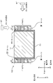
- FIG. 1A is an axial cross-sectional schematic diagram of the motor according to Embodiment 1.
- FIG. 1B is a schematic diagram of a radial cross-section of the motor according to Embodiment 1.
- FIG. 1B is a schematic diagram of a radial cross-section of the motor according to Embodiment 1.
- FIG. 2 is a schematic diagram of the stator viewed from the axial direction of the motor according to the first embodiment.
- FIG. 3 is a schematic diagram of the k-th turn of the coil viewed from the radial direction.
- 4A is a cross-sectional view taken along line IVA-IVA of FIG. 2.
- FIG. 4B is a cross-sectional view taken along line IVB-IVB of FIG. 2.
- FIG. FIG. 5 is a schematic diagram of the stator according to Modification 1 as seen from the axial direction.
- FIG. 1A is an axial cross-sectional schematic diagram of the motor according to Embodiment 1.
- FIG. 1B
- FIG. 6 is an axial cross-sectional schematic diagram of a motor according to Modification 2.
- FIG. 7 is a schematic cross-sectional view of a main part of a stator of a motor according to Modification 2.
- FIG. 8 is an axial cross-sectional schematic diagram of the motor according to the second embodiment.
- FIG. 9 is an axial cross-sectional schematic diagram of another motor according to the second embodiment.
- 10 is a schematic cross-sectional view of a main part of the stator of the motor shown in FIG. 9.
- FIG. FIG. 11 is an axial cross-sectional schematic diagram of a motor of another modification.
- FIG. 12 is a schematic axial cross-sectional view of a motor of still another modification.
- FIG. 1A is an axial cross-sectional schematic diagram of the motor 1000 according to the first embodiment.
- FIG. 1B is a schematic diagram of a radial cross-section of the motor 1000 according to the first embodiment.
- the radial direction of the motor 1000 will be referred to as the "radial direction”
- the outer peripheral direction will be referred to as the "circumferential direction”
- the direction in which the axis included in the rotating shaft 210 of the motor 1000 extends are sometimes called “axial directions” respectively.
- the shaft center side of the motor 1000 may be called inner or inner
- the outer peripheral side may be called outer or outer.
- a motor 1000 shown in FIG. 1A is attached to equipment or equipment (not shown) so that its radial direction is parallel to the direction of gravity.
- "parallel” means parallel including manufacturing tolerances of the motor 1000 and mounting tolerances to equipment, etc. It is not required that the radial direction and the gravitational direction are parallel in a strict sense.
- the side on which the end plate 310 is provided may be referred to as the upper side, and the opposite side may be referred to as the lower side.
- the axis of the motor 1000 coincides with the axis of the rotating shaft 210 when viewed in the axial direction.
- the motor 1000 has a stator 100, a rotor 200, a motor case 300, and an end plate 310.
- a cooling device 400 is attached to the motor 1000 . Details of the structures of the stator 100 and the rotor 200 will be described later.
- the motor case 300 is a cylindrical metal member with an opening at the top.
- End plate 310 is a plate-shaped metal member provided to block the opening of motor case 300 .
- the end plate 310 may be a member made of resin.
- the cooling device 400 has an oil pump 410 and a supply pipe 420 .
- the supply pipe 420 is a hollow metal member.
- the supply pipe 420 has a main pipe 430 and a branch pipe 440 .
- One end of supply pipe 420 is connected to oil pump 410 .
- Main pipe 430 extends inside motor case 300 through the radially outer side of stator 100 .
- Main pipe 430 branches inside end plate 310 .
- a branched pipe 440 extends inside the motor case 300 . Therefore, two ends of the supply pipe 420 are arranged inside the motor case 300 .
- a first injection port 431 is provided at the end of the main pipe 430 .
- a second injection port 441 is provided at the end of the branch pipe 440 .
- the first injection port 431 is arranged radially outside the first coil end 41a.
- the second injection port 441 is arranged axially above the first coil end 41a.
- a metal member may be used for the supply pipe 420 .
- the supply pipe 420 can be made of a resin member.
- the supply pipe 420 made of a resin member can be expected to have high insulating properties.
- first coil end 41a is the upper end of the coil 40 in the axial direction.
- the first coil end 41a is a portion of the coil 40 that protrudes outside the slot 30, as described above.
- the second coil end 41 b is the axial lower end of the coil 40 .
- the second coil end 41 b is a portion of the coil 40 protruding outside the slot 30 .
- Supply pipe 420 may branch outside motor case 300 or may branch inside.
- oil which is a refrigerant discharged from the oil pump 410
- oil is pressure-fed into the motor case 300 through the supply pipe 420 .
- Oil is injected toward the first coil end 41a from both the first injection port 431 and the second injection port 441 to cool the first coil end 41a.
- oil is injected from the first injection port 431 toward the radial outer surface of the first coil end 41a.
- Oil is injected from the second injection port 441 toward the axial upper side surface of the first coil end 41a. Note that the oil injected to the first coil end 41a accumulates inside the motor case 300 in a portion positioned below the axial center of the motor 1000 in the direction of gravity. The injected oil is collected in an oil reservoir (not shown).
- a plurality of first injection ports 431 are provided at the end of the main pipe 430, and a plurality of second injection ports 441 are provided at the end of the branch pipe 440, respectively. Oil is injected toward the first coil ends 41a of the plurality of coils 40 (see FIG. 2, for example).
- Each end of the main pipe 430 and the branch pipe 440 located inside the motor case 300 may extend a predetermined length in the circumferential direction.
- the stator 100 includes an annular yoke 20 and a plurality of teeth (tooth portions) 10 connected to the inner circumference of the yoke 20 and provided at equal intervals along the inner circumference. have.
- Yoke 20 to which teeth 10 are connected is sometimes called stator core 110 .
- the stator 100 further has slots 30 provided between teeth 10 adjacent in the circumferential direction, and coils 40 accommodated in the slots 30 .
- Stator 100 is arranged radially outwardly of rotor 200 with a constant gap therebetween.
- the teeth 10 and the yoke 20 are formed, for example, by punching electromagnetic steel sheets containing silicon or the like and laminating them.
- Coils 40 are mounted on respective teeth 10 with insulators 50 (see FIGS. 4A and 4B) interposed therebetween, and housed in slots 30 .
- the coil 40 has the first coil end 41 a and the second coil end 41 b as the coil ends 41 .
- the shape of the coil 40 will be detailed later.
- the coils 40 may be called coils U1-U4, V1-V4, and W1-W4, respectively.
- the rotor 200 has a rotating shaft 210 , a rotor core 220 having the rotating shaft 210 as its axis, and a plurality of magnets 230 .
- a plurality of magnets 230 are embedded inside rotor core 220 , and opposite to stator 100 , N poles and S poles are alternately arranged along the outer peripheral direction of rotating shaft 210 .
- the material, shape, and material of the magnet 230 can be changed as appropriate according to the output of the motor 1000 and the like.
- rotor core 220 is formed, for example, by laminating electromagnetic steel sheets containing silicon or the like after stamping.
- the coils U1 to U4, V1 to V4, and W1 to W4 are connected in series. Three-phase currents of U, V, and W phases having an electrical angle difference of 120° are supplied to the coils U1 to U4, V1 to V4, and W1 to W4, respectively, to excite them. As a result, a rotating magnetic field is generated in stator 100 . This rotating magnetic field interacts with the magnetic field generated by the magnets 230 provided on the rotor 200 to generate torque, and the rotating shaft 210 is supported by the bearings 320 and rotates.
- FIG. 2 is a schematic diagram of the stator viewed from the axial direction.
- FIG. 3 is a schematic diagram of the k-th turn of the coil viewed from the radial direction.
- 4A is a cross-sectional view taken along line IVA-IVA of FIG. 2.
- FIG. 4B is a cross-sectional view taken along line IVB-IVB of FIG. 2.
- illustration of the yoke 20 is omitted in FIGS. 2 and 4A and 4B.
- the number of turns of the coil 40 may be n (n is an integer equal to or greater than 2).
- the coil 40 is a component formed by spirally winding a conductive wire made of copper or the like.
- the coil 40 is a formed coil formed by forming the conducting wire.
- an insulating coating is formed on the surface of the conducting wire that constitutes the coil 40 .
- the "formed coil” in the specification of the present application does not include a coil in which a conducting wire with a constant width and thickness is wound spirally.
- a formed coil is formed, for example, by preparing a plurality of rectangular plate materials having different lengths, widths or thicknesses, and joining these plate materials by cold pressure welding, welding, or other methods.
- the material of the plate material is a low resistance material such as copper or aluminum.
- the molded coil may be formed by so-called casting, in which copper or the like is melted and poured into a mold.
- a formed coil may be formed by bending a plate-shaped conductive wire, which is previously formed to have different widths or thicknesses along the way, at predetermined positions.
- the formed coil may be formed by rolling a plate-shaped conductor wire with a constant width and thickness at a predetermined portion, changing the width or thickness in the middle, and then spirally winding the wire.
- the molded coil is formed by applying a process other than winding the conductive wire, or by a method different from simply winding.
- the coil 40 is a molded coil, the shape of each turn can be freely changed as described later.
- the outer shape of the k-th turn (k is an integer, 1 ⁇ k ⁇ n) of the coil 40 is a square ring having four sides when viewed from the radial direction. Two side portions facing each other and extending in the circumferential direction respectively correspond to the coil ends 41 .
- the coil end 41 located axially above is the first coil end 41a.
- the coil end 41 positioned axially lower is the second coil end 41b.
- two sides 42 facing each other and extending in the axial direction are housed inside the slot 30 .
- the first turn is positioned closer to the axis of the motor 1000 and the nth turn is positioned closer to the yoke 20 . That is, the n-th turn is arranged radially outside the first turn.
- the arrangement order of the 12 coils 40 arranged at equal intervals along the circumferential direction is I to XII.
- Oil is injected from the first injection port 431 and the second injection port 441 of the supply pipe 420 toward the first coil ends 41a of the coil 40 arranged at positions I, II and XII, respectively.
- the height of the first coil end 41a differs depending on the position of the coil 40 within the stator 100.
- the height of the first coil end 41a is H1
- the height of the two coil ends 41b is H2 (>H1).
- the heights of the first coil end 41a and the second coil end 41b are both H2, as shown in FIG. 4B.
- oil which is a refrigerant
- oil is directly injected to the first coil ends 41a of the coils 40 arranged at positions I, II, and XII.
- oil tends to flow into the first coil ends 41a of the coils 40 arranged at the positions III and XI respectively from the coils 40 arranged at the adjacent positions II and XII. Therefore, in the coils 40 arranged at positions I to III, XI and XII, the first coil ends 41a are cooled by heat exchange with oil. Therefore, the temperature rise of the coil 40 is suppressed.
- the oil injected to the coil 40 is temporarily stored in a portion inside the motor case 300 that is located below the axial center of the motor 1000 in the direction of gravity. Therefore, the coils 40 positioned at positions V to IX are cooled by direct contact with the accumulated oil. Therefore, the temperature rise of the coil 40 is suppressed.
- the amount of oil flowing from the coils 40 arranged at adjacent positions III and XI is reduced due to the effect of gravity.
- These coils 40 are arranged inside the motor case 300 and near the axis of the motor 1000 . Therefore, the contact area with the oil accumulated inside the motor case 300 is significantly smaller than that of the coils 40 positioned at positions V to IX.
- the cooling of the first coil ends 41a is insufficient, and the temperature of the coils 40 tends to rise. Therefore, the loss in the coil 40 increases, which can be a factor in reducing the efficiency of the motor 1000 .
- the surface area and volume of the first coil ends 41a of the coils 40 placed at the positions IV and X are increased, and the first coil ends 41a of the coils 40 placed at other positions have a larger surface area and volume. It can be larger than the amount of heat dissipation. Thereby, the temperature rise of the coils 40 arranged at the positions IV and X can be suppressed. Moreover, since the temperature rise can be suppressed in the entirety of the plurality of coils 40 arranged in the stator 100, the efficiency reduction of the motor 1000 can be suppressed.
- the coil 40 in which the height of the first coil end 41a is higher than the coils 40 at other positions is not limited to the example described above. In the coil 40 with low oil cooling efficiency, the height of the first coil end 41a may be made higher than the coils 40 at other positions. For example, if the amount of oil that accumulates inside the motor case 300 is small, the coils 40 located at positions V and IX, respectively, may also be insufficiently cooled by the oil. In such a case, the shape of the first coil ends 41a of the coils 40 located at positions V and IX, respectively, will be the same as shown in FIG. 4A. Also, if the amount of oil flowing through the coils 40 arranged at positions III and XI is small, the shape of the first coil ends 41a of these coils 40 will also be the same as shown in FIG. 4A.
- the stator 100 includes a stator core 110 formed so as to surround the axial center and having a plurality of teeth (tooth portions) 10, and coils attached to each of the plurality of teeth 10. 40 and at least.
- the coil 40 is formed by winding a conductive wire with a square cross section and stacking n turns (n is an integer equal to or greater than 2).
- a plurality of teeth 10 are connected to the inner circumference of stator core 110 at intervals along the circumferential direction, which is the outer circumference direction of motor 1000 .
- the axial direction which is the direction in which the axis of the motor 1000 extends, intersects the direction of gravity.
- the height of the coil end 41 which is the end of the coil 40 in the axial direction, is the height of the first coil end 41a in this embodiment. , is different from the other coils 40 .
- the height H2 of the first coil end 41a is set to the height of the coil 40 in which the first coil end 41a is sufficiently cooled by oil. It is higher than the height H1 of the first coil end 41a.
- the surface area and volume of the first coil end 41a can be increased, and the amount of heat radiation can be made larger than that of the first coil end 41a of the coil 40 arranged at another position.
- the structure of the oil supply pipe 420 is simplified.
- the oil supply pressure can be kept low, and an increase in the size of the oil pump 410 can be suppressed. Also, the amount of oil discharged can be reduced. As a result, the cost of the cooling device 400 and thus the cost of the motor 1000 can be reduced.
- the coil 40 is the molded coil described above, the height of the first coil end 41a can be easily changed in the coil 40 at a desired position.
- a motor 1000 includes a rotor 200 having a rotating shaft 210 as an axis, a stator 100 provided coaxially with the rotor 200 and spaced from the rotor 200 by a predetermined distance, and the stator 100 and the rotor 200. and a motor case 300 housed inside.
- the motor 1000 further includes a cooling device 400 that supplies oil, which is a coolant, toward at least one coil 40 .
- the cooling device 400 includes an oil pump (pump) 410 that discharges oil, and is connected to the oil pump 410 and extends inside the motor case 300 . It has a feed tube 420 feeding towards.
- pump oil pump
- the oil supplied from the cooling device 400 can be injected to the coil 40 to reliably cool the coil 40 which is the main heat source in the motor 1000 .
- thermal loss generated in the coil 40 can be suppressed, and the efficiency of the motor 1000 can be enhanced.
- the height H2 of the first coil end 41a is set higher than the height H1 of the first coil end 41a of the coil 40 that is cooled by oil. is doing. Furthermore, the height H2 of the first coil end 41a of the coil 40 from which oil is not directly injected is set higher than the height H1 of the first coil end 41a of the coil 40 from which oil is directly injected. . As a result, the amount of heat radiated from the first coil end 41a can be increased in the coil 40 that is not sufficiently cooled by oil. Therefore, the temperature rise can be suppressed in the entirety of the plurality of coils 40 arranged in the stator 100 . In addition, a decrease in efficiency of the motor 1000 can be suppressed.
- the structure of the supply pipe 420 is simplified, and an increase in the size of the oil pump 410 can be suppressed. Also, the amount of oil discharged can be reduced. As a result, the cost of the cooling device 400 and thus the cost of the motor 1000 can be reduced.
- the supply pipe 420 has a second injection port 441 for injecting oil in the axial direction. By doing so, it is possible to reliably spray the oil onto a region having a large surface area of the first coil end 41a.
- the supply pipe 420 preferably further has a first injection port 431 for injecting oil from above in the direction of gravity. By doing so, the first coil end 41a can be reliably cooled with oil.
- the coil end 41 has a first coil end 41a as one end in the axial direction and a second coil end 41b as the other end.
- the oil is injected toward at least the first coil end 41a.
- the coil 40 having the height H1 of the first coil end 41a and the first coil end 41a and the coil 40 having a height of H2 (>H1).
- the amount of heat released at the second coil ends 41b to which oil is not supplied can be increased.
- the temperature rise can be suppressed in the entirety of the plurality of coils 40 arranged in the stator 100, and the efficiency drop of the motor 1000 can be suppressed.
- FIG. 5 is a schematic diagram of the stator 100 according to Modification 1 as seen from the axial direction.
- the same reference numerals are given to the same parts as in the first embodiment, and detailed description thereof will be omitted.
- the stator 100 and thus the motor 1000 of this modified example differ from the stator 100 and thus the motor 1000 of the first embodiment in the position of the coil 40 where the oil is directly injected.
- oil is injected directly into coils 40 located at positions I, III and XI, respectively.
- the coils 40 located at positions I, III and XI respectively have a shape similar to that shown in FIG. 4A.
- the height of the first coil end 41a is H2, like the one shown in FIG. 4B.
- the height of the first coil end 41a is H2 as in the case shown in FIG. 4B.
- the position of the coil 40 where the height of the first coil end 41a is H2 is not particularly limited to the example shown in FIG.
- at least one coil 40 having a first coil end 41a different in height from the coil group is arranged between the coil groups in which the first coil ends 41a have the same height. All you have to do is
- the height H2 of the first coil end 41a of the coil 40 from which oil is not directly injected is set higher than the height H1 of the first coil end 41a of the coil 40 from which oil is directly injected. Raise.
- the amount of heat radiation from the first coil ends 41 a is increased, and the temperature rise of the entire plurality of coils 40 arranged in the stator 100 can be suppressed.
- a decrease in efficiency of the motor 1000 can be suppressed.
- FIG. 6 is an axial cross-sectional schematic diagram of a motor 1000 according to Modification 2.
- FIG. 7 is a schematic cross-sectional view of a main part of stator 100 of motor 1000 according to Modification 2.
- FIG. 6 For convenience of description, in FIGS. 6, 7 and subsequent drawings, the same reference numerals are given to the same parts as in the first embodiment, and detailed description thereof will be omitted.
- the motor 1000 of this modified example shown in FIG. 6 differs from the motor 1000 of Embodiment 1 shown in FIG. 1A in the shape of the supply pipe 420 .
- the main pipe 430 passes between the stator 100 and the motor case 300 and extends radially outward of the second coil end 41b.
- One first injection port 431 of the pair of first injection ports is located in the intermediate portion of the main pipe 430 and radially outward of the first coil end 41a.
- the other first injection port 432 of the pair of first injection ports is located in the intermediate portion of the main pipe 430 and radially outward of the second coil end 41b. Therefore, the oil injected from the pair of first injection ports 431 and 432 is sprayed onto the radial outer surfaces of the first coil end 41a and the second coil end 41b.
- another branch pipe 450 extends from the end of the main pipe 430 toward the axis of the motor 1000 .
- a second injection port 451 which is one of the pair of second injection ports 441 and 451 and faces the axially lower side surface of the second coil end 41b, is provided. Therefore, the oil injected from the second injection port 441 facing the first coil end 41a out of the pair of second injection ports 441, 451 is sprayed onto the axial upper side surface of the first coil end 41a, and the second coil The oil injected from the second injection port 451 facing the end 41b is sprayed onto the axial lower surface of the second coil end 41b.
- the amount of heat radiation from the first coil end 41a and the second coil end 41b can be increased.
- a temperature rise can be suppressed in the entirety of the plurality of coils 40 arranged in the stator 100 .
- a decrease in efficiency of the motor 1000 can be suppressed.
- the supply pipe 420 is not routed to the vicinity of the second coil end 41b. Therefore, the space for arranging the supply pipe 420 within the motor case 300 can be reduced. 6, the volume of the motor 1000 can be made smaller by the portion surrounded by the broken line shown in FIG. 1A. Therefore, the motor 1000 can be miniaturized.
- FIG. 8 is an axial cross-sectional schematic diagram of the motor 1000 according to the second embodiment.
- FIG. 9 is an axial cross-sectional schematic diagram of another motor 1000 according to the second embodiment.
- FIG. 10 is a schematic cross-sectional view of a main part of stator 100 of motor 1000 shown in FIG.
- a motor 1000 shown in FIG. 8 has the same configuration as the motor 1000 shown in the first embodiment.
- the surface area of the second coil end 41b which is not sprayed with oil as a coolant, is made larger than the surface area of the first coil end 41a, which is sprayed with oil.
- the volume of the second coil end 41b may be larger than the volume of the first coil end 41a.
- the heat dissipation area of the second coil end 41b can be made larger than that of the first coil end 41a. Therefore, the amount of heat released at the second coil end 41b can be increased.
- the oil is injected to the first coil end 41a, which has a small heat radiation area and tends to trap heat, heat exchange with the oil can increase the amount of heat radiation from the first coil end 41a. In other words, the heat generated in the coil 40 can be reliably dissipated without injecting oil to the second coil end 41b. Therefore, the efficiency of the motor 1000 can be improved.
- the amount of oil discharged can be reduced, the size of the oil pump 410 can be reduced. Therefore, the cost of the cooling device 400 and the cost of the motor 1000 can be reduced.
- the arrangement space of the supply pipe 420 within the motor case 300 can be reduced, as in the second modification.
- the volume of the motor 1000 can be made smaller by the portion surrounded by the dashed line shown in FIG. Therefore, the motor 1000 can be miniaturized.
- the volume of the first coil end 41a can be made smaller than the volume of the second coil end 41b. Therefore, the axial size of the motor 1000 can be reduced. Therefore, the motor 1000 can be miniaturized.
- the surface area of the second coil end 41b is appropriately set according to the amount of heat radiation required from the second coil end 41b. Also, the shapes of the first coil end 41a and the second coil end 41b can be changed as appropriate within a range in which the surface area of the first coil end 41a is smaller than the surface area of the second coil end 41b.
- the surface area of the first coil end 41a to which the oil as the coolant is sprayed may be larger than the surface area of the second coil end 41b to which the oil is not sprayed.
- the volume of the first coil end 41a may be larger than the volume of the second coil end 41b.
- the coil 40 may be actively cooled by injecting oil to the first coil end 41a having a larger surface area than the second coil end 41b.
- FIG. 10 is a schematic cross-sectional view of a main part of stator 100 of motor 1000 shown in FIG. Specifically, they correspond to the coils 40 arranged at positions I-III and V-IX shown in FIG. 2, and positions XI and XII, respectively.
- the height of the first coil end 41a is H3 (>H2), while the height of the second coil end 41b is H2 (>H1).
- the surface area and volume of the first coil end 41a can be made larger than the surface area and volume of the second coil end 41b.
- the structure that makes the surface area and volume of the first coil end 41a larger than the surface area and volume of the second coil end 41b is not particularly limited to the example shown in FIG.
- the shape of the coils 40 arranged at positions IV and X is similar to that shown in FIG. 4B.
- the heat generated in the coil 40 can be reliably dissipated without injecting oil to the second coil end 41b, and the efficiency of the motor 1000 can be improved. Since the amount of oil discharged can be reduced, the size of the oil pump 410 can be reduced. Therefore, the cost of the cooling device 400 and the cost of the motor 1000 can be reduced. Furthermore, the space for arranging the supply pipe 420 within the motor case 300 can be reduced. Therefore, the motor 1000 can be miniaturized.
- the shapes of the first coil end 41a and the second coil end 41b can be appropriately changed as long as the surface area of the first coil end 41a is larger than the surface area of the second coil end 41b.
- the shape of all coils 40 in the stator 100 may be similar to that shown in FIG. 4A. That is, in all coils 40, the height of the first coil ends 41a may be lower than the height of the second coil ends 41b. Also, in the motor 1000 shown in FIG. 10, all the coils 40 in the stator 100 may have the same shape as shown in FIG. That is, in all coils 40, the height of the first coil ends 41a may be higher than the height of the second coil ends 41b.
- a new embodiment can be obtained by appropriately combining the constituent elements shown in Embodiments 1 and 2 and Modifications 1 and 2.
- the coil 40 of Modified Example 2 shown in FIG. 7 may be applied to the stator 100 and motor 1000 shown in Embodiment 1 or Modified Example 1.
- the height of the coil end 41 is the same for each turn, but it may be different for each turn. Alternatively, it may be the same for one or more turns and different for the remaining turns.
- the motor 1000 with 3 phases and 12 slots has been described as an example.
- the motor 1000 is not particularly limited to this, and may have another structure, for example, a 3-phase 6-slot motor 1000 .
- the structure of the supply pipe 420 is also not particularly limited to the examples shown in FIGS. 1A and 6.
- the first injection ports 431 and 432 may be omitted.
- the branch pipes 440, 450 and the second injection ports 441, 451 may be omitted.
- the structure of the motor 1000 of the present disclosure is not limited to the examples shown in Embodiments 1 and 2 and Modifications 1 and 2, and may take other structures.
- FIG. 11 is an axial cross-sectional schematic diagram of a motor of another modified example.
- FIG. 12 is a schematic axial cross-sectional view of a motor of still another modification.
- the supply pipe 420 has been described as having the main pipe 430 and the branch pipe 440 . Only one supply pipe 420 may be formed. For example, as shown in FIG. 11, the supply pipe 420 may be shaped using only the main pipe 430 shown in FIG. 1A. Alternatively, the supply pipe may be shaped using only the branch pipe 440 .
- the cooling device 400 may change the direction in which the motor 1000 is attached according to the direction in which the motor 1000 is attached to the installation object.
- the motor 1000 may be installed so that the direction of gravity and the axial direction are the same.
- the oil pump 410 may be installed on the outer peripheral side in the radial direction.
- the supply pipe 420 extends inside the motor case 300 through the inside of the end plate 310, like the branch pipe 440 shown in FIG. 1A. Note that, as shown in FIG. 12, if the first injection port 431 is positioned above the coil 40 in the gravitational direction, it is possible to achieve the same effects as in the first and second embodiments described above.
- the stator of the present disclosure can ensure heat dissipation in each coil in the stator when cooling the coils with a coolant. Therefore, it is useful for application to high efficiency motors.
Abstract
Priority Applications (3)
| Application Number | Priority Date | Filing Date | Title |
|---|---|---|---|
| CN202280017630.2A CN116941162A (zh) | 2021-03-02 | 2022-02-04 | 定子和具备该定子的电动机 |
| EP22762898.9A EP4304056A1 (fr) | 2021-03-02 | 2022-02-04 | Stator et moteur équipé de celui-ci |
| JP2023503654A JPWO2022185841A1 (fr) | 2021-03-02 | 2022-02-04 |
Applications Claiming Priority (2)
| Application Number | Priority Date | Filing Date | Title |
|---|---|---|---|
| JP2021032941 | 2021-03-02 | ||
| JP2021-032941 | 2021-03-02 |
Publications (1)
| Publication Number | Publication Date |
|---|---|
| WO2022185841A1 true WO2022185841A1 (fr) | 2022-09-09 |
Family
ID=83155020
Family Applications (1)
| Application Number | Title | Priority Date | Filing Date |
|---|---|---|---|
| PCT/JP2022/004533 WO2022185841A1 (fr) | 2021-03-02 | 2022-02-04 | Stator et moteur équipé de celui-ci |
Country Status (4)
| Country | Link |
|---|---|
| EP (1) | EP4304056A1 (fr) |
| JP (1) | JPWO2022185841A1 (fr) |
| CN (1) | CN116941162A (fr) |
| WO (1) | WO2022185841A1 (fr) |
Citations (4)
| Publication number | Priority date | Publication date | Assignee | Title |
|---|---|---|---|---|
| JPH0830856B2 (ja) | 1988-03-28 | 1996-03-27 | 富士写真フイルム株式会社 | 写真処理条件設定用原画 |
| DE102012212637A1 (de) | 2012-07-18 | 2014-01-23 | Fraunhofer-Gesellschaft zur Förderung der angewandten Forschung e.V. | Gießtechnisch hergestellte elektrische Spule |
| WO2020017143A1 (fr) * | 2018-07-18 | 2020-01-23 | パナソニックIpマネジメント株式会社 | Moteur |
| WO2020105467A1 (fr) * | 2018-11-20 | 2020-05-28 | ジヤトコ株式会社 | Structure de refroidissement d'huile moteur |
-
2022
- 2022-02-04 JP JP2023503654A patent/JPWO2022185841A1/ja active Pending
- 2022-02-04 WO PCT/JP2022/004533 patent/WO2022185841A1/fr active Application Filing
- 2022-02-04 CN CN202280017630.2A patent/CN116941162A/zh active Pending
- 2022-02-04 EP EP22762898.9A patent/EP4304056A1/fr active Pending
Patent Citations (4)
| Publication number | Priority date | Publication date | Assignee | Title |
|---|---|---|---|---|
| JPH0830856B2 (ja) | 1988-03-28 | 1996-03-27 | 富士写真フイルム株式会社 | 写真処理条件設定用原画 |
| DE102012212637A1 (de) | 2012-07-18 | 2014-01-23 | Fraunhofer-Gesellschaft zur Förderung der angewandten Forschung e.V. | Gießtechnisch hergestellte elektrische Spule |
| WO2020017143A1 (fr) * | 2018-07-18 | 2020-01-23 | パナソニックIpマネジメント株式会社 | Moteur |
| WO2020105467A1 (fr) * | 2018-11-20 | 2020-05-28 | ジヤトコ株式会社 | Structure de refroidissement d'huile moteur |
Also Published As
| Publication number | Publication date |
|---|---|
| EP4304056A1 (fr) | 2024-01-10 |
| CN116941162A (zh) | 2023-10-24 |
| JPWO2022185841A1 (fr) | 2022-09-09 |
Similar Documents
| Publication | Publication Date | Title |
|---|---|---|
| US11025138B2 (en) | Electric machine | |
| US20220166275A1 (en) | High performance electromagnetic machine and cooling system | |
| US7649299B2 (en) | Rotating electrical machine and alternating-current generator | |
| US20160028284A1 (en) | Electric machine | |
| US20040095035A1 (en) | Electric motor | |
| EP3588743B1 (fr) | Moteur | |
| EP2136455A1 (fr) | Moteur électrique fourni avec un agencement de refroidissement | |
| CA2677020A1 (fr) | Moteur annulaire | |
| US11165310B2 (en) | Stator for a rotating electric machine having dielectric regions for a winding head board | |
| US20150270754A1 (en) | Dual-rotor electric rotating machine | |
| JP4665454B2 (ja) | モータ | |
| JP2019161752A (ja) | 回転電機のステータ | |
| JP2016208757A (ja) | 車両用回転電機 | |
| EP3588744B1 (fr) | Moteur | |
| CN110313113B (zh) | 马达 | |
| WO2022185841A1 (fr) | Stator et moteur équipé de celui-ci | |
| JP6076711B2 (ja) | かご形誘導電動機 | |
| CN114846728A (zh) | 线圈以及具备该线圈的定子、马达 | |
| US11289979B2 (en) | Rotary electric machine | |
| WO2022185842A1 (fr) | Bobine et moteur équipé de celle-ci | |
| US20220200367A1 (en) | Stator for electrical machines | |
| JP2016129447A (ja) | 回転電機 | |
| JPWO2022185841A5 (fr) | ||
| JPWO2022185842A5 (fr) | ||
| WO2023106338A1 (fr) | Moteur |
Legal Events
| Date | Code | Title | Description |
|---|---|---|---|
| 121 | Ep: the epo has been informed by wipo that ep was designated in this application |
Ref document number: 22762898 Country of ref document: EP Kind code of ref document: A1 |
|
| ENP | Entry into the national phase |
Ref document number: 2023503654 Country of ref document: JP Kind code of ref document: A |
|
| WWE | Wipo information: entry into national phase |
Ref document number: 202280017630.2 Country of ref document: CN |
|
| WWE | Wipo information: entry into national phase |
Ref document number: 2022762898 Country of ref document: EP |
|
| NENP | Non-entry into the national phase |
Ref country code: DE |
|
| ENP | Entry into the national phase |
Ref document number: 2022762898 Country of ref document: EP Effective date: 20231002 |