WO2022185468A1 - Tower deterioration detection device, tower deterioration detection system, and tower deterioration detection method - Google Patents
Tower deterioration detection device, tower deterioration detection system, and tower deterioration detection method Download PDFInfo
- Publication number
- WO2022185468A1 WO2022185468A1 PCT/JP2021/008372 JP2021008372W WO2022185468A1 WO 2022185468 A1 WO2022185468 A1 WO 2022185468A1 JP 2021008372 W JP2021008372 W JP 2021008372W WO 2022185468 A1 WO2022185468 A1 WO 2022185468A1
- Authority
- WO
- WIPO (PCT)
- Prior art keywords
- deterioration
- tower
- deterioration detection
- steel tower
- optical signal
- Prior art date
Links
- 230000006866 deterioration Effects 0.000 title claims abstract description 313
- 238000001514 detection method Methods 0.000 title claims abstract description 186
- 230000003287 optical effect Effects 0.000 claims abstract description 103
- 239000013307 optical fiber Substances 0.000 claims abstract description 64
- 229910000831 Steel Inorganic materials 0.000 claims description 168
- 239000010959 steel Substances 0.000 claims description 168
- 238000004891 communication Methods 0.000 claims description 22
- 230000005856 abnormality Effects 0.000 claims description 14
- 239000003973 paint Substances 0.000 claims description 6
- JEIPFZHSYJVQDO-UHFFFAOYSA-N iron(III) oxide Inorganic materials O=[Fe]O[Fe]=O JEIPFZHSYJVQDO-UHFFFAOYSA-N 0.000 claims description 4
- 238000001228 spectrum Methods 0.000 description 27
- 238000010586 diagram Methods 0.000 description 23
- 238000012545 processing Methods 0.000 description 23
- 230000015654 memory Effects 0.000 description 19
- 230000006870 function Effects 0.000 description 18
- 238000000034 method Methods 0.000 description 14
- 238000010801 machine learning Methods 0.000 description 10
- 238000009434 installation Methods 0.000 description 6
- 238000012549 training Methods 0.000 description 6
- 230000005540 biological transmission Effects 0.000 description 4
- 238000012986 modification Methods 0.000 description 4
- 230000004048 modification Effects 0.000 description 4
- 238000010276 construction Methods 0.000 description 3
- 238000005516 engineering process Methods 0.000 description 3
- 239000000463 material Substances 0.000 description 3
- 230000002123 temporal effect Effects 0.000 description 3
- 230000000694 effects Effects 0.000 description 2
- 239000007787 solid Substances 0.000 description 2
- 238000012706 support-vector machine Methods 0.000 description 2
- 238000013528 artificial neural network Methods 0.000 description 1
- 239000002131 composite material Substances 0.000 description 1
- 238000013016 damping Methods 0.000 description 1
Images


Classifications
-
- G—PHYSICS
- G01—MEASURING; TESTING
- G01H—MEASUREMENT OF MECHANICAL VIBRATIONS OR ULTRASONIC, SONIC OR INFRASONIC WAVES
- G01H9/00—Measuring mechanical vibrations or ultrasonic, sonic or infrasonic waves by using radiation-sensitive means, e.g. optical means
-
- G—PHYSICS
- G01—MEASURING; TESTING
- G01M—TESTING STATIC OR DYNAMIC BALANCE OF MACHINES OR STRUCTURES; TESTING OF STRUCTURES OR APPARATUS, NOT OTHERWISE PROVIDED FOR
- G01M99/00—Subject matter not provided for in other groups of this subclass
Definitions
- the present disclosure relates to a steel tower deterioration detection device and the like.
- Patent Document 1 discloses a technique for locating a fault point in an overhead power distribution system. That is, firstly, a pulse generator for generating a pulsed input wave is installed. This input wave contains frequency components corresponding to the spatial resolution required to locate the accident point. Secondly, a measuring device is installed for measuring at least one of a potential time waveform, a current time waveform and a voltage time waveform in the overhead power distribution system. The distance to the accident point is calculated based on the time difference between the application of the input wave and the generation of the reflected wave corresponding to the input wave (see, for example, the summary of Patent Document 1).
- Patent Document 2 The technology described in Patent Document 2 is also known as a related technology.
- the power transmission system includes steel towers for power transmission.
- the power distribution system includes steel towers for power distribution.
- the technique described in Patent Literature 1 locates a fault point in an overhead power distribution system. In other words, the technique described in Patent Literature 1 does not detect such deterioration of the steel tower. Therefore, there is a problem that deterioration of the steel tower cannot be detected.
- the present disclosure has been made to solve the above-described problems, and aims to provide a tower deterioration detection device or the like that can detect deterioration of a tower.
- One form of the steel tower deterioration detection device includes optical signal receiving means for receiving an optical signal from an optical fiber cable laid on the steel tower, and detecting deterioration of the steel tower based on the vibration pattern of the steel tower indicated by the optical signal. and a deterioration detecting means for detecting the deterioration.
- the optical signal receiving means receives an optical signal from an optical fiber cable laid on the steel tower, and the deterioration detection means detects the vibration pattern of the steel tower indicated by the optical signal. Based on this, the deterioration of the steel tower is detected.
- deterioration of the steel tower can be detected.
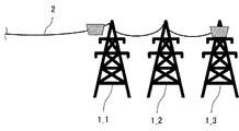
- FIG. 1 is an explanatory diagram showing an installation example of an optical fiber cable laid by an aerial method via a plurality of steel towers.
- FIG. 2 is a block diagram showing essential parts of a steel tower deterioration detection system according to the second embodiment.
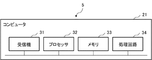
- FIG. 3 is a block diagram showing the hardware configuration of main parts of the tower deterioration detection device according to the second embodiment.
- FIG. 4 is a block diagram showing another hardware configuration of main parts of the tower deterioration detection device according to the second embodiment.
- FIG. 5 is a block diagram showing another hardware configuration of main parts of the tower deterioration detection device according to the second embodiment.
- FIG. 6 is a flow chart showing the operation of the steel tower deterioration detection device according to the second embodiment.
- FIG. 7 is an explanatory diagram showing an example of tower information used by the deterioration detection unit.
- FIG. 8A is an explanatory diagram showing an example of a frequency spectrum corresponding to a vibration pattern of a steel tower without deterioration.
- FIG. 8B is an explanatory diagram showing an example of a frequency spectrum corresponding to a vibration pattern of a deteriorated steel tower.
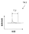
- FIG. 9A is an explanatory diagram showing an example of a time waveform corresponding to a vibration pattern of a steel tower without deterioration.
- FIG. 9B is an explanatory diagram showing an example of a temporal waveform corresponding to the vibration pattern of a deteriorated steel tower.
- FIG. 10 is an explanatory diagram showing an example of data used for machine learning.
- FIG. 10 is an explanatory diagram showing an example of data used for machine learning.
- FIG. 11 is an explanatory diagram showing an example of a learning device used for machine learning.
- FIG. 12A is an explanatory diagram showing an example of a frequency spectrum corresponding to a vibration pattern of a steel tower at a past time.
- FIG. 12B is an explanatory diagram showing an example of the frequency spectrum corresponding to the vibration pattern of the steel tower at another past time.
- FIG. 12C is an explanatory diagram showing an example of the frequency spectrum corresponding to the vibration pattern of the steel tower at the current time.
- FIG. 12D is an explanatory diagram showing an example of a frequency spectrum corresponding to the vibration pattern of the steel tower at a future point in time.
- FIG. 13 is an explanatory diagram showing another example of tower information used by the deterioration detection unit.
- FIG. 12A is an explanatory diagram showing an example of a frequency spectrum corresponding to a vibration pattern of a steel tower at a past time.
- FIG. 12B is an explanatory diagram showing an example of the frequency spectrum corresponding to the
- FIG. 14 is a block diagram showing essential parts of another steel tower deterioration detection system according to the second embodiment.
- FIG. 15 is a block diagram showing the essential parts of another steel tower deterioration detection device according to the second embodiment.
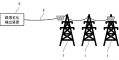
- FIG. 16 is an explanatory diagram showing an installation example of an optical fiber cable laid by an aerial method via a steel tower deterioration detection device and a plurality of steel towers according to the first embodiment.
- FIG. 16 is an explanatory diagram showing the steel tower deterioration detection device according to the first embodiment.
- a steel tower deterioration detection device according to the first embodiment will be described with reference to FIG. 16 .
- the optical fiber cable 2 is laid by an aerial method via a plurality of steel towers 1 .
- a tower deterioration detector 5 is provided at one end of the optical fiber cable 2 .
- the tower deterioration detection device 5 has the following functions.
- the tower deterioration detection device 5 outputs an optical signal to the optical fiber cable 2 .
- backscattered light is generated inside the optical fiber cable 2 .
- the tower deterioration detection device 5 receives an optical signal corresponding to the generated backscattered light.
- the tower deterioration detector 5 receives the optical signal from the optical fiber cable 2 .
- the received optical signal includes different patterns depending on the vibration of each steel tower 1 .
- the tower deterioration detection device 5 uses the received optical signal to detect deterioration of each tower 1 based on the pattern. Details of the tower deterioration detection device 5 will be described later in the second embodiment.
- deterioration of the steel tower 1 can be detected by using the steel tower deterioration detection device 5 .
- FIG. 1 is an explanatory diagram showing an installation example of an optical fiber cable laid by an aerial method via a plurality of steel towers.
- FIG. 2 is a block diagram showing essential parts of a steel tower deterioration detection system according to the second embodiment. A steel tower deterioration detection system according to a second embodiment will be described with reference to FIGS. 1 and 2.
- FIG. 1 is an explanatory diagram showing an installation example of an optical fiber cable laid by an aerial method via a plurality of steel towers.
- FIG. 2 is a block diagram showing essential parts of a steel tower deterioration detection system according to the second embodiment. A steel tower deterioration
- an optical fiber cable 2 is laid by an aerial method via N steel towers 1_1 to 1_N.
- N is an integer of 2 or more.
- N 3.
- the towers 1_1 to 1_N are included in a power grid or distribution grid. In other words, the towers 1_1 to 1_N are for transmission or distribution.
- the optical fiber cable 2 is for communication or sensing.
- the optical fiber cable 2 may be provided inside the overhead ground wire. That is, the optical fiber cable 2 may use OPGW (Optical Fiber Composite Overhead Ground Wire).
- the optical fiber cable 2 is used for communication by the optical communication device 3 (see FIG. 2).
- the optical communication device 3 is configured by, for example, a terminal device for OPGW.
- the optical communication device 3 is installed, for example, in a station building for OPGW.
- the tower deterioration detection system 100 includes an optical fiber cable 2, a filter unit 4, a tower deterioration detection device 5 and an output device 6.
- the tower deterioration detector 5 includes an optical signal receiver 11 , a deterioration detector 12 and an output controller 13 .
- the filter unit 4 is provided between the optical fiber cable 2, the optical communication device 3, and the tower deterioration detection device 5.
- the filter unit 4 When the optical signal from the optical communication device 3 is input, the filter unit 4 outputs the input optical signal to the optical fiber cable 2 . Further, when the optical signal from the optical fiber cable 2 is input, the filter unit 4 separates the component corresponding to the backscattered light from the input signal light and outputs the component to the tower deterioration detection device 5 .
- the filter unit 4 is configured using a wavelength filter (more specifically, a 3-port wavelength division multiplexing filter). In such a wavelength filter, an optical signal (having a specific wavelength) input from the optical communication device 3 is output to the optical fiber cable 2 without being output to the tower deterioration detection device 5 .
- components having other specific wavelengths (including components corresponding to backscattered light) in the optical signal input from the optical fiber cable 2 are not output to the optical communication device 3, and are not subject to tower deterioration. It is output to the detection device 5 .
- the function of the filter unit 4 is realized.
- the optical signal receiving unit 11 receives optical signals from the optical fiber cable 2 . More specifically, as described above, the filter unit 4 separates the component corresponding to the backscattered light, and the optical signal receiver 11 receives the optical signal including the separated component.
- the deterioration detector 12 uses the optical signal received by the optical signal receiver 11 to detect deterioration of each steel tower 1 . More specifically, the deterioration detection unit 12 detects the presence or absence of deterioration in each steel tower 1 and also detects the degree of deterioration in each steel tower 1 . Alternatively, the deterioration detection unit 12 detects signs of deterioration in individual steel towers 1 . A specific example of the detection method by the deterioration detection unit 12 will be described later with reference to FIGS. 7 to 12D.
- the output control unit 13 executes control to output information indicating the result of detection by the deterioration detection unit 12 (hereinafter referred to as "detection result information").
- An output device 6 is used to output the detection result information.
- the output device 6 includes, for example, at least one of a display device, an audio output device and a communication device.
- the display device uses, for example, a display.
- the audio output device uses, for example, a speaker.
- a communication device for example, uses a dedicated transmitter and receiver.
- the output control unit 13 executes control to display an image including detection result information.
- a display device of the output device 6 is used for displaying such an image.
- the output control unit 13 executes control to output a sound corresponding to the detection result information.
- An audio output device among the output devices 6 is used for outputting such audio.
- the output control unit 13 executes control to transmit a signal corresponding to the detection result information.
- a communication device in the output device 6 is used for transmitting such signals.
- the main part of the steel tower deterioration detection system 100 is configured.
- optical signal receiving section 11 may be referred to as “optical signal receiving means”.
- deterioration detection unit 12 may be referred to as “deterioration detection means”.
- output control unit 13 may be referred to as "output control means”.
- the tower deterioration detection device 5 uses a computer 21.
- FIG. The computer 21 may be installed in the same place as the optical communication device 3 (for example, a station building for OPGW). Alternatively, the computer 21 may be located elsewhere (eg, within a cloud network). Alternatively, some elements of the computer 21 (more specifically, the receiver 31) are provided at the same location, and the remaining elements of the computer 21 are provided at the other location. can be
- the computer 21 comprises a receiver 31, a processor 32 and a memory 33.
- the memory 33 stores a program for causing the computer 21 to function as the optical signal receiving section 11, the deterioration detecting section 12, and the output control section 13 (including a program for causing the receiver 31 to function as the optical signal receiving section 11). remembered.
- the processor 32 reads and executes programs stored in the memory 33 . Thereby, the function F1 of the optical signal receiver 11, the function F2 of the deterioration detector 12, and the function F3 of the output controller 13 are realized.
- the computer 21 comprises a receiver 31 and a processing circuit 34, as shown in FIG.
- the processing circuit 34 performs processing for causing the computer 21 to function as the optical signal receiving section 11, deterioration detecting section 12, and output control section 13 (including processing for causing the receiver 31 to function as the optical signal receiving section 11). Run. Thereby, functions F1 to F3 are realized.
- the computer 21 comprises a receiver 31, a processor 32, a memory 33 and a processing circuit 34.
- some of the functions F1 to F3 are implemented by the processor 32 and the memory 33, and the rest of the functions F1 to F3 are implemented by the processing circuit .
- the processor 32 is composed of one or more processors.
- the individual processors use, for example, CPUs (Central Processing Units), GPUs (Graphics Processing Units), microprocessors, microcontrollers, or DSPs (Digital Signal Processors).
- CPUs Central Processing Units
- GPUs Graphics Processing Units
- microprocessors microcontrollers
- DSPs Digital Signal Processors
- the memory 33 is composed of one or more memories. Individual memories include, for example, RAM (Random Access Memory), ROM (Read Only Memory), flash memory, EPROM (Erasable Programmable Read Only Memory), EEPROM (Electrically Erasable Programmable Read Only Memory), hard disk drive, solid state drive, solid state memory Flexible discs, compact discs, DVDs (Digital Versatile Discs), Blu-ray discs, MO (Magneto Optical) discs, or mini discs are used.
- RAM Random Access Memory
- ROM Read Only Memory
- flash memory EPROM (Erasable Programmable Read Only Memory), EEPROM (Electrically Erasable Programmable Read Only Memory), hard disk drive, solid state drive, solid state memory Flexible discs, compact discs, DVDs (Digital Versatile Discs), Blu-ray discs, MO (Magneto Optical) discs, or mini discs are used.
- the processing circuit 34 is composed of one or more processing circuits. Individual processing circuits use, for example, ASIC (Application Specific Integrated Circuit), PLD (Programmable Logic Device), FPGA (Field Programmable Gate Array), SoC (System a Chip), or system LSI (Large Scale) is.
- ASIC Application Specific Integrated Circuit
- PLD Programmable Logic Device
- FPGA Field Programmable Gate Array
- SoC System a Chip
- system LSI Large Scale Scale
- the processor 32 may include a dedicated processor corresponding to each of the functions F1-F3.
- the memory 33 may include dedicated memory corresponding to each of the functions F1-F3.
- the processing circuitry 34 may include dedicated processing circuitry corresponding to each of the functions F1-F3.
- the optical signal receiving unit 11 receives an optical signal from the optical fiber cable 2 (step ST1).
- the deterioration detector 12 detects deterioration of each steel tower 1 using the received optical signal (step ST2).
- the output control unit 13 executes control to output information indicating the result of the detection (that is, detection result information) (step ST3).
- step ST3 detection result information indicating that there is no deterioration is output.
- step ST3 detection result information is output indicating that there is deterioration and indicating the degree of deterioration (for example, one of two values).
- the deterioration detector 12 detects the presence or absence of deterioration in each steel tower 1 and also detects the degree of deterioration.
- the optical communication device 3 outputs a pulsed optical signal.
- the output optical signal is input to the optical fiber cable 2 via the filter unit 4 .
- backscattered light is generated inside the optical fiber cable 2 .
- the optical signal received by the optical signal receiving section 11 is separated by the filter unit 4, and the component corresponding to the generated backscattered light (hereinafter referred to as "backscattered light component”) is include.
- the optical signal received by the optical signal receiving unit 11 includes components corresponding to backscattered light generated at positions corresponding to individual steel towers 1 in the optical fiber cable 2 .
- the received optical signal contains backscattered light components corresponding to individual pylons 1 .
- the timing at which the backscattered light component is received depends on the position at which the corresponding steel tower 1 is installed and the position at which the steel tower deterioration detection device 5 is installed (more specifically, the position at which the receiver 31 is installed). It differs depending on the distance D.
- the distance D is the route distance along the optical fiber cable 2 .
- the backscattered light component included in the optical signal received by the optical signal receiving unit 11 exhibits different patterns (hereinafter referred to as "vibration patterns") depending on the vibration of the corresponding steel tower 1.
- the received optical signal contains vibration patterns corresponding to individual pylons 1 . Deterioration detection by the deterioration detector 12 is based on such a vibration pattern.
- the vibration pattern changes due to the occurrence of such a structural abnormality.
- the attenuation time T in the time waveform TW indicating the vibration pattern changes.
- the peak frequency in the frequency spectrum FS indicating the vibration pattern changes. Therefore, it is possible to detect the presence or absence of deterioration (more specifically, deterioration due to structural abnormality) in each steel tower 1 based on the vibration pattern.
- the amount of change in the vibration pattern (for example, the amount of change in damping time T or the amount of change in peak frequency) varies depending on the degree of deterioration. More specifically, the larger the degree of deterioration, the larger the amount of change. Therefore, the degree of deterioration (more specifically, deterioration due to structural abnormality) in each steel tower 1 can be detected based on the vibration pattern.
- the tower deterioration detection device 5 stores information about each tower 1 (hereinafter referred to as “tower information”).
- the pylon information includes information indicating the distance D corresponding to each pylon 1 (hereinafter referred to as “distance information”).
- the tower information includes information (hereinafter referred to as “identification information”) that can identify each tower 1 .
- the identification information includes, for example, identifiers assigned to individual steel towers 1 .
- FIG. 7 shows an example of tower information.
- the tower deterioration detection device 5 acquires information indicating the timing at which the optical communication device 3 outputs the pulsed optical signal. Such information is acquired from the optical communication device 3, for example.
- the deterioration detector 12 calculates the time difference between the timing indicated by the acquired information and the timing at which the optical signal receiver 11 receives the backscattered light component.
- the deterioration detection unit 12 calculates the distance D' between the position where the backscattered light component is generated and the position where the receiver 31 is installed, based on the calculated time difference.
- the distance D' is the path distance along the optical fiber cable 2 .
- the deterioration detection unit 12 compares the calculated distance D' with individual distances D indicated by the distance information included in the tower information. Thereby, the deterioration detector 12 detects the backscattered light component corresponding to each steel tower 1 among the backscattered light components contained in the received optical signal. As a result, vibration patterns corresponding to individual steel towers 1 are detected. More specifically, a time waveform TW representing a vibration pattern corresponding to each steel tower 1 is detected.
- the deterioration detection unit 12 executes fast Fourier transform (FFT) on the detected temporal waveform. Thereby, a frequency spectrum FS representing a vibration pattern corresponding to each steel tower 1 is calculated.
- FFT fast Fourier transform
- FIG. 8A shows an image of the frequency spectrum FS_1 showing the vibration pattern corresponding to steel tower 1 without deterioration.
- FIG. 8B shows an image of the frequency spectrum FS_2 showing the vibration pattern corresponding to the steel tower 1 with deterioration.
- P_1 in FIG. 8A indicates a peak in the frequency spectrum FS_1.
- P_2 in FIG. 8B indicates a peak in the frequency spectrum FS_2.
- the peak frequency in the frequency spectrum FS changes.
- the peak frequency in frequency spectrum FS_2 (see FIG. 8B) is a different value from the peak frequency in frequency spectrum FS_1 (see FIG. 8A).
- a reference value to be compared with the peak frequency is set in the deterioration detection unit 12 .
- the reference value is set to a value equivalent to the peak frequency in the frequency spectrum FS showing the vibration pattern corresponding to the steel tower 1 without deterioration.
- the reference value is set to a value equivalent to the peak frequency in the frequency spectrum FS_1 shown in FIG. 8A.
- the deterioration detection unit 12 detects the peak frequency in the calculated frequency spectrum FS.
- the deterioration detector 12 compares the detected peak frequency with the set reference value. Thereby, the deterioration detection unit 12 determines whether or not the corresponding steel tower 1 is deteriorated. Thus, the presence or absence of deterioration in each steel tower 1 is detected.
- the tower deterioration detection device 5 (more specifically, the storage area of the memory 33 or the processing circuit 34) stores a value indicating the degree of deterioration (for example, a two-step value) and a value indicating the amount of change in the peak frequency. Information indicating the correspondence is stored.
- the deterioration detection unit 12 calculates the amount of change in the detected peak frequency with respect to the set reference value.
- the deterioration detection unit 12 uses the stored information to determine the degree of deterioration corresponding to the calculated amount of change. Thereby, the degree of deterioration in the corresponding steel tower 1 is detected.
- the deterioration detector 12 detects the presence or absence of deterioration in each steel tower 1 and also detects the degree of deterioration.
- the deterioration detection unit 12 detects backscattered light components corresponding to individual steel towers 1 by a detection method similar to the detection method described in the first specific example. As a result, vibration patterns corresponding to individual steel towers 1 are detected. More specifically, a time waveform TW representing a vibration pattern corresponding to each steel tower 1 is detected.
- the decay time T of the pulse has a different value depending on the presence or absence of deterioration in the corresponding steel tower 1 .
- the amount of change in the decay time T of the pulse has a different value depending on the degree of deterioration in the corresponding steel tower 1 . This is as described in the first specific example.
- FIG. 9A shows an image of a temporal waveform TW_1 showing a vibration pattern corresponding to steel tower 1 without deterioration.
- FIG. 9B shows an image of a time waveform TW_2 showing a vibration pattern corresponding to the steel tower 1 with deterioration.
- T_1 in FIG. 9A indicates the decay time of the pulse in the time waveform TW_1.
- T_2 in FIG. 9B indicates the decay time of the pulse in the time waveform TW_2.
- a reference value to be compared with the decay time T is set in the deterioration detection unit 12 .
- the reference value is set to a value equivalent to the attenuation time T in the time waveform TW representing the vibration pattern corresponding to the steel tower 1 without deterioration.
- the reference value is set to a value equivalent to the decay time T_1 in the time waveform TW_1 shown in FIG. 9A.
- the deterioration detection unit 12 calculates the decay time T of the pulse.
- the deterioration detection unit 12 compares the calculated decay time T with the set reference value. Thereby, the deterioration detection unit 12 detects the presence or absence of deterioration in the corresponding steel tower 1 .
- a value indicating the degree of deterioration for example, a value in two stages
- a value indicating the amount of change in the decay time T are stored. information indicating the correspondence relationship between .
- the deterioration detection unit 12 calculates the amount of change in the calculated attenuation time T with respect to the set reference value.
- the deterioration detection unit 12 uses the stored information to determine the degree of deterioration corresponding to the calculated amount of change. Thereby, the degree of deterioration in the corresponding steel tower 1 is detected.
- the deterioration detector 12 detects the presence or absence of deterioration in each steel tower 1 and also detects the degree of deterioration.
- the third specific example uses a trained model generated by machine learning. More specifically, the third specific example uses a trained model generated by supervised learning. Such machine learning will be described below.
- vibration data data indicating multiple vibration patterns (hereinafter referred to as "vibration data") are prepared as training input data used for machine learning.
- the vibration data includes vibration patterns corresponding to individual deterioration states in individual steel towers 1 .
- data indicating the steel tower 1 and the deterioration state corresponding to each vibration pattern included in the vibration data is prepared as teacher data (that is, correct data) used for machine learning.
- FIG. 10 shows an example of these data (initial training data).
- a plurality of vibration data among the initial training data illustrated in FIG. 10 are input to a dedicated learning device (see FIG. 11).
- the learning device generates a learned model by executing machine learning using these vibration data as training input data.
- the learning device receives training input data indicating vibration patterns corresponding to individual steel towers 1 .
- the learning device performs machine learning on such training input data, and repeats learning processing for each steel tower 1 until correct data is obtained with a predetermined accuracy.
- learned patterns corresponding to individual steel towers 1 are generated.
- the learning device classifies the presence or absence of deterioration and the degree of deterioration corresponding to each steel tower 1 using the input data, which is new vibration data, as the input data of the learned pattern.
- the learning device outputs information indicating the presence or absence of deterioration and the degree of deterioration in each steel tower 1 .
- FIG. 11 shows an example of machine learning learning processing and classification processing in a learning device. Thus, a trained model is generated.
- SVM support vector machine
- neural network For machine learning in the learner, various known techniques such as support vector machine (SVM) or neural network can be used. A detailed description of these techniques is omitted.
- the deterioration detector 12 uses the optical signal received by the optical signal receiver 11 to detect the vibration pattern corresponding to each steel tower 1 (see the first specific example).
- the deterioration detection unit 12 generates data indicating the detected vibration pattern.
- the deterioration detection unit 12 is provided with the generated learned model.
- the deterioration detection unit 12 inputs the generated vibration data to the learned model.
- such a learned model outputs information indicating the presence or absence of deterioration and the degree of deterioration in the corresponding steel tower 1 . As a result, the presence or absence of deterioration in each steel tower 1 is detected, and the degree of deterioration in each steel tower 1 is detected.
- the deterioration detector 12 detects signs of deterioration in individual steel towers 1 .
- the deterioration detection unit 12 periodically detects the peak frequency according to the first specific example. As a result, for example, peak frequencies at a plurality of past points in time and peak frequencies at the present point in time are detected.
- FIG. 12A shows an example of the frequency spectrum FS_P_1 at a past time (for example, two years ago).
- FIG. 12B shows an example of the frequency spectrum FS_P_2 at another past time (for example, one year ago).
- FIG. 12C shows an example of the frequency spectrum FS_C at the current time (eg current year).
- P_P_1 in FIG. 12A indicates a peak in the frequency spectrum FS_P_1.
- P_P_2 in FIG. 12B indicates a peak in the frequency spectrum FS_P_2.
- P_C in FIG. 12C indicates a peak in the frequency spectrum FS_C.
- the deterioration detection unit 12 predicts peak frequencies at future points in time based on these peak frequencies. For such prediction, for example, the method of least squares is used.
- FIG. 12D shows an example of the frequency spectrum FS_F at a future point in time (eg next year). P_F in FIG. 12D indicates a peak in the frequency spectrum FS_F.
- the deterioration detection unit 12 compares the predicted peak frequency with a reference value similar to the reference value in the first specific example. As a result, the deterioration detector 12 predicts whether or not each steel tower 1 will be deteriorated at a future point in time, and also predicts the degree of deterioration at a future point in time.
- the deterioration detection unit 12 determines that the corresponding steel tower 1 has a sign of deterioration.
- the deterioration detector 12 determines that there is no sign of deterioration for the corresponding steel tower 1 . In this way, signs of deterioration in individual steel towers 1 are detected.
- deterioration of individual steel towers 1 can be detected.
- a so-called "remote” detection can then be realized. That is, in detecting the deterioration of each steel tower 1, it is possible to eliminate the need for workers to climb each steel tower 1 and for workers to directly visually detect deterioration.
- optical fiber cables 2 for example, optical fiber cables 2 for OPGW
- the configuration can be simplified compared to the technology described in Patent Document 1. That is, it is assumed that the technique described in Patent Document 1 is used to detect deterioration of individual steel towers 1 . In this case, it is required to install a pulse generator and to install a measuring device. Moreover, where the measuring device uses an electric sensor, it is also required to install a dedicated power source. On the other hand, by using the tower deterioration detection system 100, these devices can be made unnecessary. In particular, the tower deterioration detection system 100 uses optical fiber sensing instead of electrical sensors. Therefore, it is possible to eliminate the need for a dedicated power source for the electric sensor.
- an optical communication device 3, a filter unit 4, and a steel tower deterioration detection device 5 are provided at one end of the optical fiber cable 2.
- the optical communication device 3, the filter unit 4, and the steel tower deterioration detection device 5 may be provided at each end of the optical fiber cable 2.
- the tower deterioration detection system 100 may use multiple optical fiber cables (not shown) instead of one optical fiber cable 2 .
- a plurality of optical fiber cables are provided, for example, along different routes in a power transmission network or distribution network including the towers 1_1 to 1_N.
- the optical signal receiver 11 receives optical signals from each of the plurality of optical fiber cables.
- the deterioration detection unit 12 performs the same processing as the processing described in the first, second, third, or fourth specific example for each of the plurality of optical fiber cables. Thereby, deterioration in each of the steel towers 1_1 to 1_N is detected.
- the tower information is not limited to the example shown in FIG.
- information included in the tower information is not limited to distance information and identification information.
- the tower information may include other information (hereinafter referred to as "additional information") in addition to the distance information and the identification information.
- FIG. 13 shows an example of tower information including additional information.
- the additional information includes information indicating the material of each steel tower 1, information indicating the height of each steel tower 1, and information indicating the construction year or installation year of each steel tower 1.
- the vibration pattern corresponding to each steel tower 1 differs depending on the presence or absence of deterioration and the degree of deterioration.
- the vibration pattern corresponding to each steel tower 1 may differ depending on the material, height, year of construction or year of installation, and the like.
- the deterioration detection unit 12 sets the reference value as follows when executing the processing described in the first, second, or fourth specific example. That is, the deterioration detection unit 12 sets the reference value for each steel tower 1 according to the height, material, and year of construction or year of installation indicated by the additional information. Such a reference value is set based on a predetermined rule. By using such reference values, the deterioration of individual steel towers 1 can be detected more accurately.
- the tower deterioration detection system 100 may include the optical fiber cable 2 and the tower deterioration detection device 5.
- the main part of the tower deterioration detection system 100 may be configured by the optical fiber cable 2 and the tower deterioration detection device 5 .
- the tower deterioration detection device 5 may have a function of outputting a pulsed optical signal to the optical fiber cable 2 .
- the steel tower deterioration detection device 5 may include an optical signal receiver 11 and a deterioration detector 12 .
- the optical signal receiving unit 11 and the deterioration detecting unit 12 may constitute a main part of the tower deterioration detecting device 5 .
- the output control section 13 may be provided in the output device 6 . Also in this case, the above effects can be obtained.
- the optical signal receiver 11 receives the optical signal from the optical fiber cable 2 laid on the steel tower 1 .
- the deterioration detector 12 detects deterioration of the steel tower 1 based on the vibration pattern of the steel tower 1 indicated by the optical signal. Thereby, deterioration of each steel tower 1 can be detected. In particular, such deterioration can be detected remotely.
- the electric sensor power supply and the like used in the technique described in Patent Document 1 can be eliminated, such deterioration can be detected with a simple configuration.
- [Appendix] [Appendix 1] an optical signal receiving means for receiving an optical signal from an optical fiber cable laid on a steel tower; deterioration detection means for detecting deterioration of the steel tower based on the vibration pattern of the steel tower indicated by the optical signal; A steel tower deterioration detection device.
- the structural abnormality includes at least one of loose screws in the steel tower, peeling of paint on the steel tower, and rusting on the steel tower.
- the optical signal receiving means receives the optical signals from the optical fiber cables laid on a plurality of the towers. Detection method.
- Appendix 16 16.
- the steel tower deterioration detection method according to any one of appendices 12 to 16, wherein the deterioration detecting means detects the presence or absence of the deterioration and also detects the degree of deterioration.
- Appendix 18 17.
- the steel tower deterioration detection method according to any one of appendices 12 to 16, wherein the deterioration detection means detects a sign of deterioration.
- Appendix 19 19.
- the steel tower deterioration detection method according to any one of appendices 12 to 18, wherein the output control means executes control to output information indicating a result of detection by the deterioration detection means.
- the structural abnormality includes at least one of loosening of screws in the steel tower, peeling of paint in the steel tower, and occurrence of rust in the steel tower.
- [Appendix 26] 25 The recording medium according to any one of appendices 20 to 24, wherein the deterioration detecting means detects a sign of deterioration.
Abstract
Description
図16は、第1実施形態に係る鉄塔劣化検出装置を示す説明図である。図16を参照して、第1実施形態に係る鉄塔劣化検出装置について説明する。 [First embodiment]
FIG. 16 is an explanatory diagram showing the steel tower deterioration detection device according to the first embodiment. A steel tower deterioration detection device according to the first embodiment will be described with reference to FIG. 16 .
図1は、複数本の鉄塔を介する架空方式により敷設された光ファイバケーブルの架設例を示す説明図である。図2は、第2実施形態に係る鉄塔劣化検出システムの要部を示すブロック図である。図1及び図2を参照して、第2実施形態に係る鉄塔劣化検出システムについて説明する。 [Second embodiment]
FIG. 1 is an explanatory diagram showing an installation example of an optical fiber cable laid by an aerial method via a plurality of steel towers. FIG. 2 is a block diagram showing essential parts of a steel tower deterioration detection system according to the second embodiment. A steel tower deterioration detection system according to a second embodiment will be described with reference to FIGS. 1 and 2. FIG.
[付記1]
鉄塔に敷設された光ファイバケーブルからの光信号を受信する光信号受信手段と、
前記光信号が示す前記鉄塔の振動パターンに基づき、前記鉄塔の劣化を検出する劣化検出手段と、
を備える鉄塔劣化検出装置。
[付記2]
前記劣化検出手段は、前記鉄塔の構造的異常に基づく前記劣化を検出することを特徴とする付記1に記載の鉄塔劣化検出装置。
[付記3]
前記構造的異常は、前記鉄塔におけるねじのゆるみ、前記鉄塔における塗装の剥がれ及び前記鉄塔における錆の発生のうちの少なくとも一つを含むことを特徴とする付記2に記載の鉄塔劣化検出装置。
[付記4]
前記光信号受信手段は、複数本の前記鉄塔に敷設された前記光ファイバケーブルからの前記光信号を受信することを特徴とする付記1から付記3のうちのいずれか一つに記載の鉄塔劣化検出装置。
[付記5]
前記劣化検出手段は、個々の前記鉄塔における前記劣化を検出することを特徴とする付記4に記載の鉄塔劣化検出装置。
[付記6]
前記劣化検出手段は、前記劣化の有無を検出するとともに、前記劣化の程度を検出することを特徴とする付記1から付記5のうちのいずれか一つに記載の鉄塔劣化検出装置。
[付記7]
前記劣化検出手段は、前記劣化の予兆を検出することを特徴とする付記1から付記5のうちのいずれか一つに記載の鉄塔劣化検出装置。
[付記8]
前記劣化検出手段による検出の結果を示す情報を出力する制御を実行する出力制御手段を備えることを特徴とする付記1から付記7のうちのいずれか一つに記載の鉄塔劣化検出装置。
[付記9]
付記1から付記8のうちのいずれか一つに記載の鉄塔劣化検出装置と、
前記光ファイバケーブルと、
を備える鉄塔劣化検出システム。
[付記10]
前記光ファイバケーブルは、架空地線の内部に設けられていることを特徴とする付記9に記載の鉄塔劣化検出システム。
[付記11]
前記光ファイバケーブルは、通信用又はセンシング用であることを特徴とする付記9に記載の鉄塔劣化検出システム。
[付記12]
光信号受信手段が、鉄塔に敷設された光ファイバケーブルからの光信号を受信して、
劣化検出手段が、前記光信号が示す前記鉄塔の振動パターンに基づき、前記鉄塔の劣化を検出する
ことを特徴とする鉄塔劣化検出方法。
[付記13]
前記劣化検出手段は、前記鉄塔の構造的異常に基づく前記劣化を検出することを特徴とする付記12に記載の鉄塔劣化検出方法。
[付記14]
前記構造的異常は、前記鉄塔におけるねじのゆるみ、前記鉄塔における塗装の剥がれ及び前記鉄塔における錆の発生のうちの少なくとも一つを含むことを特徴とする付記13に記載の鉄塔劣化検出方法。
[付記15]
前記光信号受信手段は、複数本の前記鉄塔に敷設された前記光ファイバケーブルからの前記光信号を受信することを特徴とする付記12から付記14のうちのいずれか一つに記載の鉄塔劣化検出方法。
[付記16]
前記劣化検出手段は、個々の前記鉄塔における前記劣化を検出することを特徴とする付記15に記載の鉄塔劣化検出方法。
[付記17]
前記劣化検出手段は、前記劣化の有無を検出するとともに、前記劣化の程度を検出することを特徴とする付記12から付記16のうちのいずれか一つに記載の鉄塔劣化検出方法。
[付記18]
前記劣化検出手段は、前記劣化の予兆を検出することを特徴とする付記12から付記16のうちのいずれか一つに記載の鉄塔劣化検出方法。
[付記19]
出力制御手段が、前記劣化検出手段による検出の結果を示す情報を出力する制御を実行することを特徴とする付記12から付記18のうちのいずれか一つに記載の鉄塔劣化検出方法。
[付記20]
コンピュータを、
鉄塔に敷設された光ファイバケーブルからの光信号を受信する光信号受信手段と、
前記光信号が示す前記鉄塔の振動パターンに基づき、前記鉄塔の劣化を検出する劣化検出手段と、
として機能させるためのプログラムを記録した記録媒体。
[付記21]
前記劣化検出手段は、前記鉄塔の構造的異常に基づく前記劣化を検出することを特徴とする付記20に記載の記録媒体。
[付記22]
前記構造的異常は、前記鉄塔におけるねじのゆるみ、前記鉄塔における塗装の剥がれ及び前記鉄塔における錆の発生のうちの少なくとも一つを含むことを特徴とする付記21に記載の記録媒体。
[付記23]
前記光信号受信手段は、複数本の前記鉄塔に敷設された前記光ファイバケーブルからの前記光信号を受信することを特徴とする付記20から付記22のうちのいずれか一つに記載の記録媒体。
[付記24]
前記劣化検出手段は、個々の前記鉄塔における前記劣化を検出することを特徴とする付記23に記載の記録媒体。
[付記25]
前記劣化検出手段は、前記劣化の有無を検出するとともに、前記劣化の程度を検出することを特徴とする付記20から付記24のうちのいずれか一つに記載の記録媒体。
[付記26]
前記劣化検出手段は、前記劣化の予兆を検出することを特徴とする付記20から付記24のうちのいずれか一つに記載の記録媒体。
[付記27]
前記プログラムは、前記コンピュータを、前記劣化検出手段による検出の結果を示す情報を出力する制御を実行する出力制御手段として機能させることを特徴とする付記20から付記26のうちのいずれか一つに記載の記録媒体。 [Appendix]
[Appendix 1]
an optical signal receiving means for receiving an optical signal from an optical fiber cable laid on a steel tower;
deterioration detection means for detecting deterioration of the steel tower based on the vibration pattern of the steel tower indicated by the optical signal;
A steel tower deterioration detection device.
[Appendix 2]
The tower deterioration detection device according to
[Appendix 3]
The pylon deterioration detection device according to
[Appendix 4]
The tower deterioration according to any one of
[Appendix 5]
4. The tower deterioration detection device according to
[Appendix 6]
The tower deterioration detection device according to any one of
[Appendix 7]
The tower deterioration detection device according to any one of
[Appendix 8]
8. The steel tower deterioration detection apparatus according to any one of
[Appendix 9]
the steel tower deterioration detection device according to any one of
the optical fiber cable;
A steel tower deterioration detection system.
[Appendix 10]
The tower deterioration detection system according to appendix 9, wherein the optical fiber cable is provided inside an overhead ground wire.
[Appendix 11]
The tower deterioration detection system according to appendix 9, wherein the optical fiber cable is for communication or sensing.
[Appendix 12]
An optical signal receiving means receives an optical signal from an optical fiber cable laid on a steel tower,
A steel tower deterioration detection method, wherein deterioration detection means detects deterioration of the steel tower based on a vibration pattern of the steel tower indicated by the optical signal.
[Appendix 13]
13. The steel tower deterioration detecting method according to
[Appendix 14]
13. The steel tower deterioration detection method according to
[Appendix 15]
15. The tower deterioration according to any one of
[Appendix 16]
16. The tower deterioration detection method according to
[Appendix 17]
17. The steel tower deterioration detection method according to any one of
[Appendix 18]
17. The steel tower deterioration detection method according to any one of
[Appendix 19]
19. The steel tower deterioration detection method according to any one of
[Appendix 20]
the computer,
an optical signal receiving means for receiving an optical signal from an optical fiber cable laid on a steel tower;
deterioration detection means for detecting deterioration of the steel tower based on the vibration pattern of the steel tower indicated by the optical signal;
A recording medium that records a program to function as
[Appendix 21]
21. The recording medium according to
[Appendix 22]
22. The recording medium according to
[Appendix 23]
23. The recording medium according to any one of
[Appendix 24]
24. The recording medium according to appendix 23, wherein the deterioration detecting means detects the deterioration in each of the steel towers.
[Appendix 25]
25. The recording medium according to any one of
[Appendix 26]
25. The recording medium according to any one of
[Appendix 27]
27. Any one of
2 光ファイバケーブル
3 光通信装置
4 フィルタユニット
5 鉄塔劣化検出装置
6 出力装置
11 光信号受信部
12 劣化検出部
13 出力制御部
21 コンピュータ
31 受信機
32 プロセッサ
33 メモリ
34 処理回路
100 鉄塔劣化検出システム 1
Claims (19)
- 鉄塔に敷設された光ファイバケーブルからの光信号を受信する光信号受信手段と、
前記光信号が示す前記鉄塔の振動パターンに基づき、前記鉄塔の劣化を検出する劣化検出手段と、
を備える鉄塔劣化検出装置。 an optical signal receiving means for receiving an optical signal from an optical fiber cable laid on a steel tower;
deterioration detection means for detecting deterioration of the steel tower based on the vibration pattern of the steel tower indicated by the optical signal;
A steel tower deterioration detection device. - 前記劣化検出手段は、前記鉄塔の構造的異常に基づく前記劣化を検出することを特徴とする請求項1に記載の鉄塔劣化検出装置。 The tower deterioration detection device according to claim 1, wherein the deterioration detection means detects the deterioration based on a structural abnormality of the tower.
- 前記構造的異常は、前記鉄塔におけるねじのゆるみ、前記鉄塔における塗装の剥がれ及び前記鉄塔における錆の発生のうちの少なくとも一つを含むことを特徴とする請求項2に記載の鉄塔劣化検出装置。 The pylon deterioration detection device according to claim 2, wherein the structural abnormality includes at least one of loosened screws in the pylon, peeling of paint on the pylon, and rust on the pylon.
- 前記光信号受信手段は、複数本の前記鉄塔に敷設された前記光ファイバケーブルからの前記光信号を受信することを特徴とする請求項1から請求項3のうちのいずれか1項に記載の鉄塔劣化検出装置。 4. The optical signal receiving means according to any one of claims 1 to 3, wherein said optical signal receiving means receives said optical signals from said optical fiber cables laid on a plurality of said steel towers. Steel tower deterioration detector.
- 前記劣化検出手段は、個々の前記鉄塔における前記劣化を検出することを特徴とする請求項4に記載の鉄塔劣化検出装置。 The tower deterioration detection device according to claim 4, wherein the deterioration detection means detects the deterioration in each of the towers.
- 前記劣化検出手段は、前記劣化の有無を検出するとともに、前記劣化の程度を検出することを特徴とする請求項1から請求項5のうちのいずれか1項に記載の鉄塔劣化検出装置。 The tower deterioration detection device according to any one of claims 1 to 5, wherein the deterioration detection means detects the presence or absence of the deterioration and also detects the degree of deterioration.
- 前記劣化検出手段は、前記劣化の予兆を検出することを特徴とする請求項1から請求項5のうちのいずれか1項に記載の鉄塔劣化検出装置。 The tower deterioration detection device according to any one of claims 1 to 5, wherein the deterioration detection means detects a sign of deterioration.
- 前記劣化検出手段による検出の結果を示す情報を出力する制御を実行する出力制御手段を備えることを特徴とする請求項1から請求項7のうちのいずれか1項に記載の鉄塔劣化検出装置。 The tower deterioration detection device according to any one of claims 1 to 7, further comprising output control means for executing control for outputting information indicating a result of detection by the deterioration detection means.
- 請求項1から請求項8のうちのいずれか1項に記載の鉄塔劣化検出装置と、
前記光ファイバケーブルと、
を備える鉄塔劣化検出システム。 A steel tower deterioration detection device according to any one of claims 1 to 8;
the optical fiber cable;
A steel tower deterioration detection system. - 前記光ファイバケーブルは、架空地線の内部に設けられていることを特徴とする請求項9に記載の鉄塔劣化検出システム。 The tower deterioration detection system according to claim 9, wherein the optical fiber cable is provided inside an overhead ground wire.
- 前記光ファイバケーブルは、通信用又はセンシング用であることを特徴とする請求項9に記載の鉄塔劣化検出システム。 The tower deterioration detection system according to claim 9, wherein the optical fiber cable is for communication or sensing.
- 光信号受信手段が、鉄塔に敷設された光ファイバケーブルからの光信号を受信して、
劣化検出手段が、前記光信号が示す前記鉄塔の振動パターンに基づき、前記鉄塔の劣化を検出する
ことを特徴とする鉄塔劣化検出方法。 An optical signal receiving means receives an optical signal from an optical fiber cable laid on a steel tower,
A steel tower deterioration detection method, wherein deterioration detection means detects deterioration of the steel tower based on a vibration pattern of the steel tower indicated by the optical signal. - 前記劣化検出手段は、前記鉄塔の構造的異常に基づく前記劣化を検出することを特徴とする請求項12に記載の鉄塔劣化検出方法。 13. The steel tower deterioration detection method according to claim 12, wherein the deterioration detection means detects the deterioration based on a structural abnormality of the steel tower.
- 前記構造的異常は、前記鉄塔におけるねじのゆるみ、前記鉄塔における塗装の剥がれ及び前記鉄塔における錆の発生のうちの少なくとも一つを含むことを特徴とする請求項13に記載の鉄塔劣化検出方法。 The steel tower deterioration detection method according to claim 13, wherein the structural abnormality includes at least one of loosening of screws in the steel tower, peeling of paint on the steel tower, and rusting on the steel tower.
- 前記光信号受信手段は、複数本の前記鉄塔に敷設された前記光ファイバケーブルからの前記光信号を受信することを特徴とする請求項12から請求項14のうちのいずれか1項に記載の鉄塔劣化検出方法。 15. The optical signal receiving means according to any one of claims 12 to 14, characterized in that said optical signal receiving means receives said optical signals from said optical fiber cables laid on a plurality of said steel towers. A steel tower deterioration detection method.
- 前記劣化検出手段は、個々の前記鉄塔における前記劣化を検出することを特徴とする請求項15に記載の鉄塔劣化検出方法。 The tower deterioration detection method according to claim 15, wherein the deterioration detection means detects the deterioration in each of the towers.
- 前記劣化検出手段は、前記劣化の有無を検出するとともに、前記劣化の程度を検出することを特徴とする請求項12から請求項16のうちのいずれか1項に記載の鉄塔劣化検出方法。 17. The steel tower deterioration detection method according to any one of claims 12 to 16, wherein the deterioration detection means detects the presence or absence of the deterioration and also detects the degree of deterioration.
- 前記劣化検出手段は、前記劣化の予兆を検出することを特徴とする請求項12から請求項16のうちのいずれか1項に記載の鉄塔劣化検出方法。 17. The steel tower deterioration detection method according to any one of claims 12 to 16, wherein the deterioration detection means detects a sign of deterioration.
- 出力制御手段が、前記劣化検出手段による検出の結果を示す情報を出力する制御を実行することを特徴とする請求項12から請求項18のうちのいずれか1項に記載の鉄塔劣化検出方法。 19. The steel tower deterioration detection method according to any one of claims 12 to 18, wherein the output control means executes control to output information indicating the result of detection by the deterioration detection means.
Priority Applications (2)
| Application Number | Priority Date | Filing Date | Title |
|---|---|---|---|
| JP2023503275A JPWO2022185468A1 (en) | 2021-03-04 | 2021-03-04 | |
| PCT/JP2021/008372 WO2022185468A1 (en) | 2021-03-04 | 2021-03-04 | Tower deterioration detection device, tower deterioration detection system, and tower deterioration detection method |
Applications Claiming Priority (1)
| Application Number | Priority Date | Filing Date | Title |
|---|---|---|---|
| PCT/JP2021/008372 WO2022185468A1 (en) | 2021-03-04 | 2021-03-04 | Tower deterioration detection device, tower deterioration detection system, and tower deterioration detection method |
Publications (1)
| Publication Number | Publication Date |
|---|---|
| WO2022185468A1 true WO2022185468A1 (en) | 2022-09-09 |
Family
ID=83155230
Family Applications (1)
| Application Number | Title | Priority Date | Filing Date |
|---|---|---|---|
| PCT/JP2021/008372 WO2022185468A1 (en) | 2021-03-04 | 2021-03-04 | Tower deterioration detection device, tower deterioration detection system, and tower deterioration detection method |
Country Status (2)
| Country | Link |
|---|---|
| JP (1) | JPWO2022185468A1 (en) |
| WO (1) | WO2022185468A1 (en) |
Citations (4)
| Publication number | Priority date | Publication date | Assignee | Title |
|---|---|---|---|---|
| JPH0583876B2 (en) * | 1988-08-31 | 1993-11-29 | Chubu Denryoku Kk | |
| JPH07280639A (en) * | 1994-04-11 | 1995-10-27 | Sumitomo Electric Ind Ltd | Abnormality diagnostic system for transmission facility based on acoustic analysis |
| JP2002152937A (en) * | 2000-11-13 | 2002-05-24 | Toshiba Corp | Anomaly signal monitor |
| WO2020044655A1 (en) * | 2018-08-30 | 2020-03-05 | 日本電気株式会社 | Utility-pole deterioration detection system, utility-pole deterioration detection device, utility-pole deterioration detection method, and non-transitory computer readable medium |
-
2021
- 2021-03-04 WO PCT/JP2021/008372 patent/WO2022185468A1/en active Application Filing
- 2021-03-04 JP JP2023503275A patent/JPWO2022185468A1/ja active Pending
Patent Citations (4)
| Publication number | Priority date | Publication date | Assignee | Title |
|---|---|---|---|---|
| JPH0583876B2 (en) * | 1988-08-31 | 1993-11-29 | Chubu Denryoku Kk | |
| JPH07280639A (en) * | 1994-04-11 | 1995-10-27 | Sumitomo Electric Ind Ltd | Abnormality diagnostic system for transmission facility based on acoustic analysis |
| JP2002152937A (en) * | 2000-11-13 | 2002-05-24 | Toshiba Corp | Anomaly signal monitor |
| WO2020044655A1 (en) * | 2018-08-30 | 2020-03-05 | 日本電気株式会社 | Utility-pole deterioration detection system, utility-pole deterioration detection device, utility-pole deterioration detection method, and non-transitory computer readable medium |
Also Published As
| Publication number | Publication date |
|---|---|
| JPWO2022185468A1 (en) | 2022-09-09 |
Similar Documents
| Publication | Publication Date | Title |
|---|---|---|
| CN112567581B (en) | Telegraph pole position specifying system, device, method and computer readable medium | |
| US11867541B2 (en) | Distributed fibre optic sensing | |
| CN109564113B (en) | Fiber optic sensing | |
| WO2020116030A1 (en) | Road monitoring system, road monitoring device, road monitoring method, and non-transitory computer-readable medium | |
| US8923663B2 (en) | Distributed fibre optic sensing | |
| WO2020044655A1 (en) | Utility-pole deterioration detection system, utility-pole deterioration detection device, utility-pole deterioration detection method, and non-transitory computer readable medium | |
| CN102762952A (en) | Fiber optic pipeline monitoring systems and methods of using the same | |
| KR101548288B1 (en) | Wiring diagnosis system using reflected wave measuring apparatus | |
| US20230152543A1 (en) | Impulse signal detection for buried cable protection using distributed fiber optic sensing | |
| WO2022185469A1 (en) | Engineering work detection device, engineering work detection system, and engineering work detection method | |
| Mišàk et al. | Towards the character and challenges of partial discharge pattern data measured on medium voltage overhead lines | |
| WO2022185468A1 (en) | Tower deterioration detection device, tower deterioration detection system, and tower deterioration detection method | |
| Maritz et al. | A travelling wave-based fault location strategy using the concepts of metric dimension and vertex covers in a graph | |
| WO2021010251A1 (en) | Optical fiber sensing system, optical fiber sensing equipment, and abnormality assessment method | |
| US20240142338A1 (en) | Tower deterioration detection device, tower deterioration detection system, and tower deterioration detection method | |
| Wang et al. | Employing fiber sensing and on-premise ai solutions for cable safety protection over telecom infrastructure | |
| KR20210024829A (en) | Apparatus and method for identifying path of optical cable | |
| JP7380891B2 (en) | Unidentified sound extraction device and unidentified sound extraction method | |
| WO2022201342A1 (en) | Lightning strike detection device, lightning strike detection system, and lightning strike detection method | |
| US20230010341A1 (en) | Detection system, detection device, and detection method | |
| US9851461B1 (en) | Modular processing system for geoacoustic sensing | |
| WO2020116031A1 (en) | Railroad monitoring system, railroad monitoring device, railroad monitoring method, and non-transitory computer-readable medium | |
| RU2639927C1 (en) | Method of acoustic detection and localization of knot holes in the trunk gas pipelines and control of state of insulators and disconnectors of overhead line of cathodic protection of pipelines and system for its implementation | |
| WO2022113252A1 (en) | Position specifying system, vibration generator, and position specifying method | |
| KR102347816B1 (en) | Apparatus for determining partial discharge |
Legal Events
| Date | Code | Title | Description |
|---|---|---|---|
| 121 | Ep: the epo has been informed by wipo that ep was designated in this application |
Ref document number: 21929042 Country of ref document: EP Kind code of ref document: A1 |
|
| ENP | Entry into the national phase |
Ref document number: 2023503275 Country of ref document: JP Kind code of ref document: A |
|
| WWE | Wipo information: entry into national phase |
Ref document number: 18279178 Country of ref document: US |
|
| NENP | Non-entry into the national phase |
Ref country code: DE |
|
| 122 | Ep: pct application non-entry in european phase |
Ref document number: 21929042 Country of ref document: EP Kind code of ref document: A1 |