WO2022181716A1 - Battery pack - Google Patents
Battery pack Download PDFInfo
- Publication number
- WO2022181716A1 WO2022181716A1 PCT/JP2022/007716 JP2022007716W WO2022181716A1 WO 2022181716 A1 WO2022181716 A1 WO 2022181716A1 JP 2022007716 W JP2022007716 W JP 2022007716W WO 2022181716 A1 WO2022181716 A1 WO 2022181716A1
- Authority
- WO
- WIPO (PCT)
- Prior art keywords
- stacking direction
- battery
- assembled battery
- length
- holding member
- Prior art date
Links
- 125000006850 spacer group Chemical group 0.000 claims description 181
- 229910052751 metal Inorganic materials 0.000 claims description 9
- 239000002184 metal Substances 0.000 claims description 9
- 229920005989 resin Polymers 0.000 claims description 3
- 239000011347 resin Substances 0.000 claims description 3
- 240000007594 Oryza sativa Species 0.000 claims 1
- 235000007164 Oryza sativa Nutrition 0.000 claims 1
- 235000009566 rice Nutrition 0.000 claims 1
- 230000014509 gene expression Effects 0.000 description 29
- 238000013461 design Methods 0.000 description 22
- 230000005484 gravity Effects 0.000 description 19
- 238000003754 machining Methods 0.000 description 9
- 230000003247 decreasing effect Effects 0.000 description 8
- 239000000470 constituent Substances 0.000 description 7
- 238000007599 discharging Methods 0.000 description 7
- 230000000694 effects Effects 0.000 description 6
- 238000004519 manufacturing process Methods 0.000 description 6
- 210000000078 claw Anatomy 0.000 description 5
- 230000007423 decrease Effects 0.000 description 5
- 238000009434 installation Methods 0.000 description 5
- 229910052782 aluminium Inorganic materials 0.000 description 4
- XAGFODPZIPBFFR-UHFFFAOYSA-N aluminium Chemical compound [Al] XAGFODPZIPBFFR-UHFFFAOYSA-N 0.000 description 4
- 238000005520 cutting process Methods 0.000 description 4
- 238000010586 diagram Methods 0.000 description 4
- 238000000034 method Methods 0.000 description 4
- 229920003002 synthetic resin Polymers 0.000 description 4
- 239000000057 synthetic resin Substances 0.000 description 4
- 229910000838 Al alloy Inorganic materials 0.000 description 3
- 239000007769 metal material Substances 0.000 description 3
- 238000012986 modification Methods 0.000 description 3
- 230000004048 modification Effects 0.000 description 3
- 238000001746 injection moulding Methods 0.000 description 2
- 230000000149 penetrating effect Effects 0.000 description 2
- HBBGRARXTFLTSG-UHFFFAOYSA-N Lithium ion Chemical compound [Li+] HBBGRARXTFLTSG-UHFFFAOYSA-N 0.000 description 1
- 230000005856 abnormality Effects 0.000 description 1
- 238000005452 bending Methods 0.000 description 1
- 238000002485 combustion reaction Methods 0.000 description 1
- 238000009429 electrical wiring Methods 0.000 description 1
- 239000003792 electrolyte Substances 0.000 description 1
- 238000002347 injection Methods 0.000 description 1
- 239000007924 injection Substances 0.000 description 1
- 238000005304 joining Methods 0.000 description 1
- 229910001416 lithium ion Inorganic materials 0.000 description 1
- 239000000463 material Substances 0.000 description 1
- 238000005259 measurement Methods 0.000 description 1
- 238000012544 monitoring process Methods 0.000 description 1
- 238000000465 moulding Methods 0.000 description 1
- 238000003825 pressing Methods 0.000 description 1
- 238000012545 processing Methods 0.000 description 1
- 102220101621 rs3852522 Human genes 0.000 description 1
- 238000004904 shortening Methods 0.000 description 1
- 238000003466 welding Methods 0.000 description 1
Images


Classifications
-
- B—PERFORMING OPERATIONS; TRANSPORTING
- B60—VEHICLES IN GENERAL
- B60L—PROPULSION OF ELECTRICALLY-PROPELLED VEHICLES; SUPPLYING ELECTRIC POWER FOR AUXILIARY EQUIPMENT OF ELECTRICALLY-PROPELLED VEHICLES; ELECTRODYNAMIC BRAKE SYSTEMS FOR VEHICLES IN GENERAL; MAGNETIC SUSPENSION OR LEVITATION FOR VEHICLES; MONITORING OPERATING VARIABLES OF ELECTRICALLY-PROPELLED VEHICLES; ELECTRIC SAFETY DEVICES FOR ELECTRICALLY-PROPELLED VEHICLES
- B60L50/00—Electric propulsion with power supplied within the vehicle
- B60L50/50—Electric propulsion with power supplied within the vehicle using propulsion power supplied by batteries or fuel cells
- B60L50/60—Electric propulsion with power supplied within the vehicle using propulsion power supplied by batteries or fuel cells using power supplied by batteries
- B60L50/64—Constructional details of batteries specially adapted for electric vehicles
-
- H—ELECTRICITY
- H01—ELECTRIC ELEMENTS
- H01M—PROCESSES OR MEANS, e.g. BATTERIES, FOR THE DIRECT CONVERSION OF CHEMICAL ENERGY INTO ELECTRICAL ENERGY
- H01M10/00—Secondary cells; Manufacture thereof
- H01M10/60—Heating or cooling; Temperature control
- H01M10/64—Heating or cooling; Temperature control characterised by the shape of the cells
- H01M10/647—Prismatic or flat cells, e.g. pouch cells
-
- H—ELECTRICITY
- H01—ELECTRIC ELEMENTS
- H01M—PROCESSES OR MEANS, e.g. BATTERIES, FOR THE DIRECT CONVERSION OF CHEMICAL ENERGY INTO ELECTRICAL ENERGY
- H01M50/00—Constructional details or processes of manufacture of the non-active parts of electrochemical cells other than fuel cells, e.g. hybrid cells
- H01M50/20—Mountings; Secondary casings or frames; Racks, modules or packs; Suspension devices; Shock absorbers; Transport or carrying devices; Holders
- H01M50/204—Racks, modules or packs for multiple batteries or multiple cells
- H01M50/207—Racks, modules or packs for multiple batteries or multiple cells characterised by their shape
- H01M50/209—Racks, modules or packs for multiple batteries or multiple cells characterised by their shape adapted for prismatic or rectangular cells
-
- H—ELECTRICITY
- H01—ELECTRIC ELEMENTS
- H01M—PROCESSES OR MEANS, e.g. BATTERIES, FOR THE DIRECT CONVERSION OF CHEMICAL ENERGY INTO ELECTRICAL ENERGY
- H01M50/00—Constructional details or processes of manufacture of the non-active parts of electrochemical cells other than fuel cells, e.g. hybrid cells
- H01M50/20—Mountings; Secondary casings or frames; Racks, modules or packs; Suspension devices; Shock absorbers; Transport or carrying devices; Holders
- H01M50/218—Mountings; Secondary casings or frames; Racks, modules or packs; Suspension devices; Shock absorbers; Transport or carrying devices; Holders characterised by the material
- H01M50/22—Mountings; Secondary casings or frames; Racks, modules or packs; Suspension devices; Shock absorbers; Transport or carrying devices; Holders characterised by the material of the casings or racks
- H01M50/222—Inorganic material
- H01M50/224—Metals
-
- H—ELECTRICITY
- H01—ELECTRIC ELEMENTS
- H01M—PROCESSES OR MEANS, e.g. BATTERIES, FOR THE DIRECT CONVERSION OF CHEMICAL ENERGY INTO ELECTRICAL ENERGY
- H01M50/00—Constructional details or processes of manufacture of the non-active parts of electrochemical cells other than fuel cells, e.g. hybrid cells
- H01M50/20—Mountings; Secondary casings or frames; Racks, modules or packs; Suspension devices; Shock absorbers; Transport or carrying devices; Holders
- H01M50/233—Mountings; Secondary casings or frames; Racks, modules or packs; Suspension devices; Shock absorbers; Transport or carrying devices; Holders characterised by physical properties of casings or racks, e.g. dimensions
-
- H—ELECTRICITY
- H01—ELECTRIC ELEMENTS
- H01M—PROCESSES OR MEANS, e.g. BATTERIES, FOR THE DIRECT CONVERSION OF CHEMICAL ENERGY INTO ELECTRICAL ENERGY
- H01M50/00—Constructional details or processes of manufacture of the non-active parts of electrochemical cells other than fuel cells, e.g. hybrid cells
- H01M50/20—Mountings; Secondary casings or frames; Racks, modules or packs; Suspension devices; Shock absorbers; Transport or carrying devices; Holders
- H01M50/249—Mountings; Secondary casings or frames; Racks, modules or packs; Suspension devices; Shock absorbers; Transport or carrying devices; Holders specially adapted for aircraft or vehicles, e.g. cars or trains
-
- H—ELECTRICITY
- H01—ELECTRIC ELEMENTS
- H01M—PROCESSES OR MEANS, e.g. BATTERIES, FOR THE DIRECT CONVERSION OF CHEMICAL ENERGY INTO ELECTRICAL ENERGY
- H01M50/00—Constructional details or processes of manufacture of the non-active parts of electrochemical cells other than fuel cells, e.g. hybrid cells
- H01M50/20—Mountings; Secondary casings or frames; Racks, modules or packs; Suspension devices; Shock absorbers; Transport or carrying devices; Holders
- H01M50/262—Mountings; Secondary casings or frames; Racks, modules or packs; Suspension devices; Shock absorbers; Transport or carrying devices; Holders with fastening means, e.g. locks
- H01M50/264—Mountings; Secondary casings or frames; Racks, modules or packs; Suspension devices; Shock absorbers; Transport or carrying devices; Holders with fastening means, e.g. locks for cells or batteries, e.g. straps, tie rods or peripheral frames
-
- H—ELECTRICITY
- H01—ELECTRIC ELEMENTS
- H01M—PROCESSES OR MEANS, e.g. BATTERIES, FOR THE DIRECT CONVERSION OF CHEMICAL ENERGY INTO ELECTRICAL ENERGY
- H01M50/00—Constructional details or processes of manufacture of the non-active parts of electrochemical cells other than fuel cells, e.g. hybrid cells
- H01M50/20—Mountings; Secondary casings or frames; Racks, modules or packs; Suspension devices; Shock absorbers; Transport or carrying devices; Holders
- H01M50/289—Mountings; Secondary casings or frames; Racks, modules or packs; Suspension devices; Shock absorbers; Transport or carrying devices; Holders characterised by spacing elements or positioning means within frames, racks or packs
- H01M50/291—Mountings; Secondary casings or frames; Racks, modules or packs; Suspension devices; Shock absorbers; Transport or carrying devices; Holders characterised by spacing elements or positioning means within frames, racks or packs characterised by their shape
-
- H—ELECTRICITY
- H01—ELECTRIC ELEMENTS
- H01M—PROCESSES OR MEANS, e.g. BATTERIES, FOR THE DIRECT CONVERSION OF CHEMICAL ENERGY INTO ELECTRICAL ENERGY
- H01M50/00—Constructional details or processes of manufacture of the non-active parts of electrochemical cells other than fuel cells, e.g. hybrid cells
- H01M50/30—Arrangements for facilitating escape of gases
- H01M50/35—Gas exhaust passages comprising elongated, tortuous or labyrinth-shaped exhaust passages
- H01M50/367—Internal gas exhaust passages forming part of the battery cover or case; Double cover vent systems
-
- B—PERFORMING OPERATIONS; TRANSPORTING
- B60—VEHICLES IN GENERAL
- B60L—PROPULSION OF ELECTRICALLY-PROPELLED VEHICLES; SUPPLYING ELECTRIC POWER FOR AUXILIARY EQUIPMENT OF ELECTRICALLY-PROPELLED VEHICLES; ELECTRODYNAMIC BRAKE SYSTEMS FOR VEHICLES IN GENERAL; MAGNETIC SUSPENSION OR LEVITATION FOR VEHICLES; MONITORING OPERATING VARIABLES OF ELECTRICALLY-PROPELLED VEHICLES; ELECTRIC SAFETY DEVICES FOR ELECTRICALLY-PROPELLED VEHICLES
- B60L2240/00—Control parameters of input or output; Target parameters
- B60L2240/40—Drive Train control parameters
- B60L2240/54—Drive Train control parameters related to batteries
- B60L2240/545—Temperature
-
- B—PERFORMING OPERATIONS; TRANSPORTING
- B60—VEHICLES IN GENERAL
- B60L—PROPULSION OF ELECTRICALLY-PROPELLED VEHICLES; SUPPLYING ELECTRIC POWER FOR AUXILIARY EQUIPMENT OF ELECTRICALLY-PROPELLED VEHICLES; ELECTRODYNAMIC BRAKE SYSTEMS FOR VEHICLES IN GENERAL; MAGNETIC SUSPENSION OR LEVITATION FOR VEHICLES; MONITORING OPERATING VARIABLES OF ELECTRICALLY-PROPELLED VEHICLES; ELECTRIC SAFETY DEVICES FOR ELECTRICALLY-PROPELLED VEHICLES
- B60L2240/00—Control parameters of input or output; Target parameters
- B60L2240/40—Drive Train control parameters
- B60L2240/54—Drive Train control parameters related to batteries
- B60L2240/547—Voltage
-
- B—PERFORMING OPERATIONS; TRANSPORTING
- B60—VEHICLES IN GENERAL
- B60L—PROPULSION OF ELECTRICALLY-PROPELLED VEHICLES; SUPPLYING ELECTRIC POWER FOR AUXILIARY EQUIPMENT OF ELECTRICALLY-PROPELLED VEHICLES; ELECTRODYNAMIC BRAKE SYSTEMS FOR VEHICLES IN GENERAL; MAGNETIC SUSPENSION OR LEVITATION FOR VEHICLES; MONITORING OPERATING VARIABLES OF ELECTRICALLY-PROPELLED VEHICLES; ELECTRIC SAFETY DEVICES FOR ELECTRICALLY-PROPELLED VEHICLES
- B60L2240/00—Control parameters of input or output; Target parameters
- B60L2240/40—Drive Train control parameters
- B60L2240/54—Drive Train control parameters related to batteries
- B60L2240/549—Current
-
- H—ELECTRICITY
- H01—ELECTRIC ELEMENTS
- H01M—PROCESSES OR MEANS, e.g. BATTERIES, FOR THE DIRECT CONVERSION OF CHEMICAL ENERGY INTO ELECTRICAL ENERGY
- H01M2220/00—Batteries for particular applications
- H01M2220/20—Batteries in motive systems, e.g. vehicle, ship, plane
-
- Y—GENERAL TAGGING OF NEW TECHNOLOGICAL DEVELOPMENTS; GENERAL TAGGING OF CROSS-SECTIONAL TECHNOLOGIES SPANNING OVER SEVERAL SECTIONS OF THE IPC; TECHNICAL SUBJECTS COVERED BY FORMER USPC CROSS-REFERENCE ART COLLECTIONS [XRACs] AND DIGESTS
- Y02—TECHNOLOGIES OR APPLICATIONS FOR MITIGATION OR ADAPTATION AGAINST CLIMATE CHANGE
- Y02E—REDUCTION OF GREENHOUSE GAS [GHG] EMISSIONS, RELATED TO ENERGY GENERATION, TRANSMISSION OR DISTRIBUTION
- Y02E60/00—Enabling technologies; Technologies with a potential or indirect contribution to GHG emissions mitigation
- Y02E60/10—Energy storage using batteries
Definitions
- the present invention relates to an assembled battery in which a plurality of batteries are stacked.
- a battery having a plurality of stacked battery cells (an example of a plurality of batteries), a busbar case fixed to the plurality of battery cells, and a plurality of covers covering and protecting the busbar case.
- Patent Document 1 a battery having a plurality of stacked battery cells (an example of a plurality of batteries), a busbar case fixed to the plurality of battery cells, and a plurality of covers covering and protecting the busbar case.
- the present invention has been made to solve such problems, and provides an assembled battery that can minimize changes in constituent elements even if the number of constituent batteries (for example, battery cells) changes.
- the challenge is to
- the assembled battery of the present invention which has been made in view of the above problems, includes a plurality of stacked batteries, a first holding member that holds the plurality of batteries from one end side in the stacking direction, and a plurality of the batteries in the stacking direction. It has a second holding member that holds from the other end side, and a connecting member that connects the first holding member and the second holding member along the stacking direction.
- the first holding member extends over a first length along the stacking direction from the one end side to a first position in direct or indirect contact with the battery. The first length is longer than or equal to the second length along the stacking direction of the battery.
- FIG. 1 is a perspective view of an assembled battery according to a first embodiment
- FIG. 1 is an exploded perspective view of an assembled battery according to a first embodiment
- FIG. FIG. 2 is a plan view of a block of the assembled battery according to the first embodiment
- FIG. 2 is a plan view of the busbar case assembly of the assembled battery according to the first embodiment
- the perspective view of the assembled battery which concerns on 2nd Embodiment The exploded perspective view of the assembled battery which concerns on 2nd Embodiment.
- FIG. 2 is a configuration diagram of a power supply device provided with two assembled batteries in which a plurality of battery cells are stacked.
- FIG. 2 is a configuration diagram of a power supply device including four assembled batteries in which a plurality of battery cells are stacked.
- 1 is a plan view conceptually showing an embodiment of an assembled battery of the present invention;
- FIG. 2 is a plan view conceptually showing another embodiment of the assembled battery of the present invention.
- FIG. 18 is a plan view showing a part of the configuration of the assembled battery of FIG. 17; The top view which shows a part of structure based on the modification of the assembled battery of 6th Embodiment. The top view which shows a part of structure of the assembled battery which concerns on 7th Embodiment. The top view of the assembled battery which concerns on 8th Embodiment.
- FIG. 15 is a plan view conceptually showing one embodiment of the assembled battery of the present invention.
- the assembled battery 100 includes a plurality of battery cells (cells) 101, a first terminal member 102 that holds the plurality of battery cells 101 from one end in the stacking direction, and a second terminal member that holds the battery cells 101 from the other end in the stacking direction. It has a member 103 and a connecting member 104 connecting the first terminating member 102 and the second terminating member 103 .
- the first end member 102 protrudes from the connection position P1 in the stacking direction with the connection member 104 toward the battery cell 101 by a predetermined length L4.
- the thickness is L2 or more.
- 15 represents the connection position of the second end member 103 with the connection member 104 in the stacking direction.
- Assembled batteries with different specifications can be obtained. For example, by using a terminating member that is thinner by the thickness of one battery cell than the predetermined length L4 that the first terminating member 102 protrudes, an assembled battery with a specification in which the number of battery cells 101 is increased by one is formed. be able to. Also, for example, by using a termination member that is thicker than the predetermined length L4 of the first termination member 102 by the thickness of one battery cell, an assembled battery with a specification in which the number of battery cells 101 is reduced by one is produced. can be formed.
- the assembled batteries when mounting assembled batteries having different numbers of battery cells in two electric vehicles of the same model but different battery specifications, the assembled batteries can be mounted without changing the vehicle body structure for mounting them. , or can be installed with few modifications and can be a common vehicle platform.
- common vehicle parts can be used without changing the layout of electrical wiring and the layout of exhaust gas passages for exhaust gas discharged from the battery cells.
- it becomes necessary to increase the number of battery cells mounted on the vehicle due to a model change of the vehicle it has become possible to reduce the number of battery cells mounted on the vehicle due to improved battery performance. can be easily handled without changing the size of the entire assembled battery.
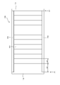
- FIG. 16 is a plan view conceptually showing another embodiment of the assembled battery of the present invention.
- the assembled battery 200 includes a plurality of stacked battery cells (single cells) 201, spacers 202 stacked together with the plurality of battery cells 201, and a holder that holds the plurality of battery cells 201 and spacers 202 along the stacking direction. and a member 203 .
- the holding member 203 holds the plurality of battery cells 201 and the spacers 202 over a constant total length L1 determined along the stacking direction.
- the spacer 202 has a thickness L3 in the stacking direction of the spacer 202 that is equal to or greater than the thickness L2 of the battery cell 201 in the stacking direction.
- an assembled battery having the same outer shape but a different number of battery cells 201 can be obtained.
- a spacer that is thinner than the thickness L3 of the spacer 202 by the thickness of one battery cell it is possible to form an assembled battery with specifications in which the number of battery cells 201 is increased by one.
- a spacer that is thicker than the thickness L3 of the spacer 202 by the thickness of one battery cell it is possible to form an assembled battery with specifications in which the number of battery cells 201 is reduced by one.
- the battery cell 1 as shown in FIG. It has a discharge element and an insulating case.
- a rechargeable secondary battery such as a lithium ion secondary battery is used as the battery cell 1 .
- the battery cell 1 of the first embodiment corresponds to the unit cell of the assembled battery according to one embodiment of the present invention.
- the battery can 2 has a rectangular parallelepiped shape with one end of the internal space open, and is made of aluminum or an aluminum alloy.
- the battery can 2 has a pair of opposing side plates 2a with a large area, a pair of opposing side plates 2b with a small area, and a bottom plate 2c on the side opposite to the opening.
- a charging/discharging element is accommodated while being covered with an insulating case, and electrolyte is injected.
- the positive electrode of the charge/discharge element is connected to the positive terminal 4 and the negative electrode of the charge/discharge element is connected to the negative terminal 5 .
- the battery lid 3 has the same rectangular flat plate shape as the bottom plate 2c, is made of aluminum or an aluminum alloy, and closes the opening of the battery can 2.
- the battery lid 3 is joined to the opening of the battery can 2 by joining means such as laser welding.
- the battery cover 3 is formed with an injection hole (not shown) penetrating therethrough.
- a gas discharge valve 6 is provided in the central portion of the battery lid 3 .
- the gas discharge valve 6 is opened when the battery cell 1 generates heat due to an abnormality such as overcharging and gas is generated, and the pressure inside the battery can 2 rises and reaches a predetermined pressure, and the gas is released from the inside of the container. is discharged, the pressure inside the battery can 2 is reduced.
- through holes are formed at one end and the other end of the battery cover 3, and a positive electrode terminal 4 and a negative electrode terminal 5 are attached thereto.
- the portions of the positive electrode terminal 4 and the negative electrode terminal 5 exposed to the outside from the battery lid 3 are each formed as a rectangular parallelepiped and have a flat top surface.
- the power generated by the battery cell 1 is supplied to an external device via the positive terminal 4 and the negative terminal 5, or the power generated externally via the positive terminal 4 and the negative terminal 5 is supplied to the charge/discharge element. is charged.
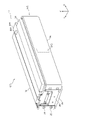
- the assembled battery 10 is mounted in, for example, a hybrid vehicle driven by an internal combustion engine and a motor or an electric vehicle driven by a motor, and used as a drive source for the motor.
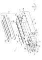
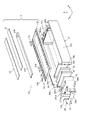
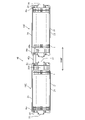
- the assembled battery 10 has a block 11 and a busbar case assembly 12, as shown in FIG.
- the block 11 includes a plurality of stacked battery cells 1 and spacers 21, a first end spacer 22, a second end spacer 23, a pair of side rails 24 and 25, It has a pair of end plates 26 , 27 and a plurality of bolts 28 .
- the block 11 has a laminate structure in which the stacked battery cells 1 and spacers 21 and each component are integrated.
- the block 11 has a pair of side rails 24 and 25 and a bus bar case assembly 12 of constant length.
- the spacers 21 are made of insulating synthetic resin, and as shown in FIG. 3, are alternately sandwiched between adjacent battery cells 1 and stacked together with the battery cells 1 in the X direction.
- Each spacer 21 has a concave portion corresponding to the shape of the battery cell 1 on both sides, and the concave portion holds the battery cell 1 and regulates the Y and Z directions.
- the spacer 21 has a claw portion provided on the upper portion in the Z direction, and is fitted with a claw portion provided on a bus bar case 35 to be described later.
- the first end spacer 22 has insulating properties, is made of synthetic resin that is harder than the spacer 21, and is arranged to face the battery cell 1 located at one end in the stacking direction.
- the first end spacer 22 has a concave portion corresponding to the shape of the battery cell 1 on the surface facing the battery cell 1.
- the concave portion holds the battery cell 1 and regulates the Y and Z directions.
- a fixing bolt hole 22 a and a negative electrode connection terminal 22 b are provided on the side of the first end spacer 22 facing the end plate 27 .
- a fixing bolt hole 22d for fixing each component is formed in the upper part of the first end spacer 22 in the Z direction.
- the second end spacer 23 has insulating properties, is made of synthetic resin that is harder than the spacer 21, and is arranged adjacent to the battery cell 1 positioned on the other end in the stacking direction. As shown in FIG. 3, the second end spacer 23 is formed with a plurality of rectangular lightening holes to prevent deformation caused by dents after molding, so-called sink marks.
- the second end spacer 23 has a concave portion corresponding to the battery cell 1 on the surface facing the battery cell 1. The concave portion holds the battery cell 1 and regulates the Y direction and the Z direction.
- a fixing bolt hole 23a, a positive electrode connection terminal 23b, and a gas exhaust duct fixing hole 23d are formed on the side of the second end spacer 23 facing the end plate 26.
- the first end spacer 22 and the second end spacer 23 of the first embodiment correspond to the end members of the assembled battery according to one embodiment of the present invention, and the fixing bolt holes 22a and 23a are intended for installation of the assembled battery.
- the positive electrode connection terminal 23b and the negative electrode connection terminal 22b correspond to the connection terminals that are electrically connected to the cell and electrically connected to the outside of the assembled battery
- the gas discharge duct fixing hole 23d corresponds to a fixing portion of a gas discharge duct for discharging gas discharged from the unit cell to the outside of the assembled battery.
- the distance from the fixing bolt hole 23a to the facing surface 23f facing the battery cell is greater than or equal to the thickness of the battery cell 1 in the stacking direction.
- the second end spacer 23 is thicker in the stacking direction than the regular-size end member (regular end member) used when the number of cells is x, by the amount corresponding to n stacked battery cells 1 . thickly formed.
- x is the maximum number of stacked battery cells 1 that can be stacked in the block 11
- n is an integer smaller than the number x of the stacked battery cells 1. It is preferably an even number in order to make That is, n and x have a relationship of n ⁇ x.
- the thickness of n stacked battery cells 1 includes the thickness of the spacer sandwiched between the battery cells 1 .
- the thickness of the battery cell 1 is increased by an integer multiple. For example, when the thickness of the second end spacer 23 is thicker than the regular end member by twice the thickness of the battery cell 1, the number of cells is larger than when the regular end member is used. In the block 11 in which an assembled battery with two fewer cells can be produced and the number of cells is 24 when the regular end members are used, the number of cells is reduced by using the second end spacers 23 instead of the regular end members. 22 blocks 11 can be formed.
- the positions of the fixing bolt hole 23a, the positive electrode connection terminal 23b, and the gas discharge duct fixing hole 23d are the same as the positions of the regular end member.
- the case where the second end spacer 23 is thicker than the thickness of one battery cell 1 has been described.
- a spacer 22 having a thickness larger than that of one battery cell may be used.
- Both the first end spacer 22 and the second end spacer 23 may be made thicker than the thickness of one battery cell 1 .
- the first end spacer 22 of the first embodiment corresponds to the first end plate or the second end plate of the assembled battery according to one embodiment of the invention
- the second end spacer 23 corresponds to the first end plate or the second end plate. Corresponds to the second end plate.
- the side rail 24 is formed of a metal material, and as shown in FIG. 3, has a rail body 24c extending in the X direction and bent portions 24b that are bent in the Y direction at both ends of the rail body 24c and face each other.
- Each bent portion 24b is provided with a fixing hole 24a penetrating in the X direction.
- the bent portion 24 b is arranged to face the first end spacer 22 and the second end spacer 23 from outside in the stacking direction, and covers part of the first end spacer 22 and part of the second end spacer 23 .
- the side rails 24 hold and bind the first end spacers 22, the plurality of battery cells 1, the plurality of spacers 21, and the second end spacers 23 while pressing them in the stacking direction.
- the side rail 24 is fixed to the end plates 26 and 27 by inserting the bolt 28 through the fixing hole 24a of the bent portion 24b.
- the side rails 24 have a length enough to stack 22 battery cells 1 when the second end spacers 23 are used.
- the side rails 25 are mirror images of the side rails 24 and have the same shape.
- the side rails 25 are made of the same metal material as the side rails 24 and have the same functions as the side rails 24 .
- the side rails 25 are arranged to face the side rails 24 in the Y direction with the stacked battery cells 1 interposed therebetween. and bending portions 25b that are bent and face each other.
- the bent portion 25b has a fixing hole 25a through which the bolt 28 is inserted.
- the pair of side rails 24 and 25 of the first embodiment respectively correspond to the side members of the assembled battery according to one embodiment of the present invention.
- the end plate 26 is made of a plate-shaped metal material, so-called sheet metal, and is arranged adjacent to the second end spacer 23 as shown in FIG.
- the end plate 26 has a flat portion 26a formed with a positioning through hole for the second end spacer 23, and a fixing portion 26b for fixing the side rail 24 and the side rail 25.
- the fixing portion 26b has a fixing hole 26c through which the bolt 28 is inserted.
- the fixed portion 26b has a step recessed in the stacking direction with respect to the flat portion 26a. It is configured so that the portion does not protrude from the surface of the flat portion 26a.
- a nut is attached to the fixing portion 26b.
- the fixing portion 26b of the first embodiment corresponds to the connecting portion with the side member of the assembled battery according to one embodiment of the present invention.
- the end plate 27 is formed similarly to the end plate 26 and is arranged adjacent to the first end spacer 22 as shown in FIG. Bent portions 24 b and 25 b of end plate 27 , side rail 24 and side rail 25 are fastened with bolts 28 .
- the pair of end plates 26 and 27 of the first embodiment respectively correspond to the end members of the assembled battery according to one embodiment of the present invention.
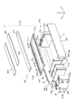
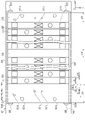
- the busbar case assembly 12 includes a busbar 31, a harness, a gas discharge duct 234, a plurality of covers 34, and a busbar case 35, as shown in FIG.
- the busbar case assembly 12 has functions such as electrical connection between the terminals of the battery cells 1 and the controller, voltage and temperature monitoring, and gas discharge.
- the bus bar 31 has an inter-cell bus bar 31a, a negative electrode bus bar 31b, and a positive electrode bus bar 31c.
- the inter-cell bus bar 31 a has a configuration for electrically connecting the positive terminal 4 and the negative terminal 5 of the battery cell 1 .
- the negative bus bar 31 b is connected to the second end spacer 23 and the positive bus bar 31 c is connected to the first end spacer 22 .
- the negative electrode bus bar 31b has a shape longer in the stacking direction of the battery cells 1 than in the case of the regular end member.
- the harness has a terminal portion, an electric wire portion, a temperature sensor portion, and a connector portion.
- the terminal portion electrically connects the bus bar 31 and the harness via the electric wire portion.
- the temperature sensor unit is in contact with the battery lid 3, measures the temperature of the battery lid 3, and outputs the measurement result.
- the connector section is connected to each component and connects each component to a controller (not shown). Each component is stored in the busbar case 35 .
- the gas discharge duct 234 has a gas discharge port 233 , collects the gas discharged from the gas discharge valve (not shown) in the center of the busbar case 35 in the Y direction, and discharges it from the gas discharge port 233 .
- the gas discharge duct 234 is fixed to the internal threads of the first end spacer 22 and the second end spacer 23 with screws arranged at both ends in the X direction.
- a plurality of covers 34 have the function of insulating and protecting the components of the busbar case assembly 12, and are arranged so as to cover the busbars 31 and the harness. Each cover 34 is fitted and fixed to the busbar case 35 .
- the busbar case 35 has a plurality of frames arranged in the stacking direction of the battery cells 1, and is configured to accommodate the inter-cell busbars 31a, the negative electrode busbars 31b, and the positive electrode busbars 31c in the frames.
- the busbar case 35 has a plurality of claw portions, and the claw portions and the claw portions provided on the Z-direction upper portions of the spacers 21, the first end spacers 22, and the second end spacers 23 of the block 11 are connected. It is configured to fix the busbar case assembly 12 to the block 11 by fitting.
- the assembled battery 10 according to the first embodiment has a second end spacer 23, and the second end spacer 23 separates the battery cells 1 from n battery cells 1 more than the regular end member used when the number of cells is x.
- the thickness in the stacking direction is increased by the number of layers that are stacked.
- the overall lengths of the side rails 24 and 25 are the same before and after the change regardless of the change in the number of battery cells 1 included in the block 11 .
- the positions of the fixing bolt hole 23a, the positive electrode connection terminal 23b, and the gas discharge duct fixing hole 23d are also the same.
- the assembled battery 10 it is possible to easily provide a combination of an assembled battery of 24 battery cells 1 in the block 11 and an assembled battery of 22 battery cells 1 in the block 11 .
- an assembled battery according to an embodiment of the present invention may be configured with a structure other than the structure of the first embodiment.
- the assembled battery 10A according to the second embodiment to the assembled battery 10D according to the fifth embodiment which are configured with structures other than the structure of the first embodiment, will be described with reference to the drawings. Note that the same reference numerals are used for the same configurations as in the assembled battery 10 according to the first embodiment, and detailed description thereof is omitted. (Second embodiment)
- FIG. 6 is a perspective view of the assembled battery according to the second embodiment
- FIG. 7 is an exploded perspective view of the assembled battery according to the second embodiment.
- a characteristic feature of this embodiment is that the fixing bolt holes 26Ab and the gas discharge duct fixing holes 26Ae are provided in the end plate 26A instead of the end spacer 23A.
- an assembled battery 10A is composed of a block 11A and a busbar case assembly 12A.
- the block 11A includes a plurality of battery cells 1, a plurality of spacers 21, a first end spacer 22A, a second end spacer 23A, a pair of side rails 24, 25, It has a pair of end plates 26 A, 27 A and a plurality of bolts 28 .
- the first end spacer 22A has a flat facing surface facing the end plate 27A on one side in the stacking direction, and a recess corresponding to the battery cell 1 is formed on the other side in the stacking direction. It has a configuration to hold and regulate the Y and Z directions.
- the second end spacer 23A has a flat facing surface facing the end plate 26A on the other side in the stacking direction, and a recess corresponding to the battery cell 1 is formed on the one side in the stacking direction. It has a configuration to hold and regulate the Y and Z directions.
- the second end spacer 23A In the second end spacer 23A, the distance between the positive electrode connection terminal 26Ac and the facing surface 23Af facing the battery cell 1, that is, the thickness of the second end spacer 23A is greater than or equal to the thickness of the battery cell 1 in the stacking direction.
- the second end spacer 23A is thicker in the stacking direction than the regular-size end member (regular end member) used when the number of cells is x, by the amount corresponding to n stacked battery cells 1. thickly formed.
- a regular end member having the same shape as the first end spacer 22A can be used.
- the second end spacer 23A which is thicker by the amount of overlapping two battery cells 1 can be used.
- the second end spacer 23A has a thickness equal to the thickness of the two battery cells 1 and the thickness of the spacer 21 interposed therebetween. There is no difference between the case and the case of 22, and they are the same. As a result, even if the number of cells is changed from 24 to 22 in block 11, the components other than the second end spacer 23 do not need to be changed in design such as size and shape, and can be used as they are.
- the end plate 26 of the first embodiment is formed of a sheet metal member
- the end plate 26A is formed of an aluminum die-cast plate member.
- the end plate 26A is arranged to face the second end spacer 23A in the X direction, which is the stacking direction.
- the end plate 26A has a fixing portion 26Aa formed with fixing bolt holes for fixing the side rails 24 and 25. As shown in FIG.
- a fixing bolt hole 26Ab and a gas discharge duct fixing hole 26Ae are formed in the end plate 26A.
- the fixing bolt holes 26Ab of the second embodiment correspond to fixing portions for fixing the assembled battery to an installation target in the assembled battery according to one embodiment of the present invention, and the gas discharge duct fixing holes 26Ae are provided from inside the cells. It corresponds to a discharge part for discharging discharged gas to the outside of the assembled battery.
- the end plate 27A is formed similarly to the end plate 26A, and is arranged adjacent to the first end spacer 22A as shown in FIG.
- a fixing bolt hole 27Ab for fixing the assembled battery 10A, a negative electrode connection terminal 27Ad, and a gas discharge duct fixing hole 27Ae are formed in the end plate 27A.
- the bent portions 24b and 25b of the end plate 27A and the side rails 24 and 25 are configured to be fastened with bolts 28.
- the pair of end plates 26A and 27A of the second embodiment respectively correspond to the end members of the assembled battery according to one embodiment of the present invention.
- the busbar case assembly 12A includes a busbar 31A, a harness, a gas discharge duct 234, a plurality of covers 34A, and a busbar case 35A.
- a busbar 31A As shown in FIG. 7, the busbar case assembly 12A includes a busbar 31A, a harness, a gas discharge duct 234, a plurality of covers 34A, and a busbar case 35A.
- the harness, cover 34A and busbar case 35A have the same functions as the harness, cover 34 and busbar case 35 of the first embodiment.
- FIG. 9 is an exploded perspective view of an assembled battery according to the third embodiment.
- the thickness of the second end spacer 23B is thinner than that of the second end spacer 23A of the second embodiment, and that the thickness of the end plate 26B is smaller than that of the end plate 26A of the second embodiment. It is thick.
- an assembled battery 10B according to the third embodiment is composed of a block 11B and the same busbar case assembly 12A as in the second embodiment.
- Block 11B has end plate 26B and end plate 27A made of die-cast aluminum like block 11A of assembled battery 10A of the second embodiment. , the shape of the end plate 26B is different.
- the second end spacer 23B has a regular size without an extended thickness, and has a concave portion corresponding to the shape of the battery cell 1 on one side in the stacking direction, and faces the end plate 26B on the other side in the stacking direction. A flat surface is formed.
- the distance from the fixing bolt hole 26Bb to the facing surface 26Bf facing the second end spacer 23B is greater than or equal to the thickness of the battery cells 1 in the stacking direction.
- the end plate 26B is thicker in the stacking direction than the regular size end member (regular end member) used when the number of cells is x, by the amount corresponding to the number of stacked n battery cells 1. It is The end plate 26B is arranged adjacent to the second end spacer 23B.
- the end plate 26B has a fixing portion 26Ba formed with fixing bolt holes for fixing the side rails 24 and 25. As shown in FIG. A fixing bolt hole 26Bb, a positive electrode connection terminal 26Bc, a negative electrode connection terminal 26Bd, and a gas discharge duct fixing hole 26Be are formed in the end plate 26B.
- the regular end member is formed thicker than the regular end member by the amount corresponding to the stack of 2 battery cells 1 .
- the end plate 26B is used.
- the positions of the fixing bolt holes 26Bb, the positive electrode connection terminal 26Bc, the negative electrode connection terminal 26Bd, and the gas discharge duct fixing holes 26Be of the end plate 26B are the same regardless of whether the battery cells 1 are 24 or 22. can be the same.
- the components other than the end plate 26B do not need to be changed in design such as size and shape, and can be used as they are.
- FIG. 10 is an exploded perspective view of the assembled battery according to the fourth embodiment.
- a characteristic feature of this embodiment is that the block 11C uses dummy cells 1C as part of the plurality of battery cells 1 .
- the assembled battery 10C according to the fourth embodiment has a block 11C as shown in FIG. It is an end member of block 11C.
- the second end spacer 23C and the end plate 26 are of regular size used when the maximum number of cells is x.
- the dummy cell 1C has the same external dimensions as the battery cell 1, and is made of a material such as an aluminum alloy.
- the dummy cell 1 ⁇ /b>C is formed by stacking n battery cells 1 adjacent to each other. For example, in the reference block 11 in which the battery cell 1 is stacked with x number of cells, if the number of cells x is reduced by 2 and changed to (x-2), two dummy cells are used instead. 1C is stacked. As shown in FIG. 10, two dummy cells 1C are arranged facing each other with a spacer 21 interposed therebetween.
- the assembled battery 10C according to the fourth embodiment only the dummy cells 1C and the negative electrode bus bar 31b are changed in accordance with the change in the cell number x of the battery cells 1, and the same effect as the assembled battery 10 according to the first embodiment can be obtained. be done.
- the second end spacer 23C is reduced.
- the positions of the fixing bolt hole 23Ca, the positive electrode connection terminal 23Cb, and the gas discharge duct fixing hole 23Cd are the same in the case of 24 battery cells 1 and in the case of 22 battery cells 1, respectively. Therefore, it is not necessary to change the design of each component such as dimensions and shapes, and the components can be used as they are.
- FIG. 11 is a perspective view of the assembled battery according to the fifth embodiment
- FIG. 12 is an exploded perspective view of the assembled battery according to the fifth embodiment.
- a characteristic feature of this embodiment is that an extension spacer 21D is provided at an intermediate position in the stacking direction of the plurality of battery cells 1 .
- the assembled battery 10D has a block 11D as shown in FIGS.
- a block 11D is configured by stacking a plurality of battery cells 1 .
- An extension spacer 21 ⁇ /b>D is interposed at an intermediate position in the stacking direction of the plurality of battery cells 1 .
- the extension spacer 21D has a thickness of n battery cells 1. For example, in a block 11 in which a maximum of x battery cells 1 can be stacked, when the number of cells is reduced by 2 to (x-2), the thickness is increased by the amount of stacking two battery cells 1.
- An extension spacer 21D is used.
- the extension spacer 21D is arranged at an intermediate position in the stacking direction in which the battery cells 1 and the spacers 21 are alternately stacked, and is displaced from the central portion in the stacking direction to the one end side.
- the plurality of battery cells 1 of the block 11D are divided into two in the stacking direction by the extension spacer 21D.
- a bus bar is attached so as to straddle the extension spacer 21D and connected to each other.
- the extension spacer 21D may be composed of two or more extension spacers. In this case, the total thickness of the widths of the two or more extension spacers is formed thicker than the thickness of the battery cell 1 .
- the extension spacer 21 ⁇ /b>D is formed thicker than the other spacers 21 .
- the extension spacer 21D may be arranged at a position other than the central portion. For example, one or two extension spacers may be arranged adjacent to the battery cell 1 closest to the second end spacer 23C or the first end spacer 22C.
- the fixing bolt of the second end spacer 23C can be used.
- the positions of the hole 23Ca, the positive electrode connection terminal 23Cb, and the gas discharge duct fixing hole 23Cd are unchanged and can be the same. Therefore, it is not necessary to change the design of each component such as dimensions and shapes, and the components can be used as they are.
- the assembled battery 10 according to the first embodiment to the assembled battery 10D according to the fifth embodiment are used as a power supply device in which a single assembled battery or a plurality of assembled batteries are arranged and electrically connected.
- FIG. 13 is a configuration diagram of a power supply device provided with two assembled batteries in which a plurality of battery cells are stacked
- FIG. 14 is a configuration diagram of a power supply device provided with four assembled batteries in which a plurality of battery cells are stacked.
- the power supply device 40 includes two assembled batteries 10E and a busbar 40a electrically connecting the two assembled batteries 10E.
- the assembled battery 10E is configured similarly to the assembled battery 10 according to the first embodiment.
- the bus bar 40a connects the positive electrode Pe of the assembled battery 10E on one side and the negative electrode Ne of the assembled battery 10E on the other side, which are arranged to face each other. They are arranged in series in close proximity.
- the assembled battery 10E corresponds to the first assembled battery or the second assembled battery of the assembled battery according to one embodiment of the present invention
- the stacking direction of the battery cells 1 corresponds to the first direction. corresponds to the first busbar.
- the stacking directions of the respective battery cells 1 of the two assembled batteries 10E may be arranged in a direction perpendicular to each other. In this case, the orthogonal direction corresponds to the second direction of the assembled battery according to one embodiment of the present invention.
- the first end spacer 22E is formed thicker by the thickness of two battery cells 1 .
- the assembled battery 10 and the assembled battery 10E have the same overall length.
- the power supply device 40 can minimize the length of the bus bar 40a.
- the power supply device 40 is mounted on the vehicle, it is arranged so as to straddle the left and right direction of the vehicle. placed. Therefore, it is possible to obtain the effect that the weight balance of the vehicle is uniform on the left and right sides.
- the power supply device 50 includes two power supply devices 40, a plate-like structure K fixed to the floor surface of two vehicle bodies (not shown), and the two power supply devices 40 as a structure.
- a plurality of bolts (not shown) for fixing to K are provided.
- the two power supply devices 40 are arranged in parallel such that the stacked battery cells 1 face each other.
- Centers of gravity G1, G2, G3, and G4 as the first center of gravity of each assembled battery 10E indicated by circles are located away from the center of the stacked battery cells 1 in the stacking direction with respect to the bus bar 40a. , is set at the center in the width direction of the assembled battery 10E orthogonal to the stacking direction.
- the center of gravity G0 as the second center of gravity of the entire structure of the power supply device 50 is located at the center in the vehicle width direction. As indicated by the dashed line, the power supply device 50 is arranged so as to straddle the left-right direction of the vehicle when it is mounted on the vehicle. part is located under the right seat RS. Therefore, the center of gravity G0 of the power supply device 50 is positioned at the central portion of the left and right seats. Note that the front, rear, left, and right directions indicate the directions viewed from the passenger of the vehicle when the passenger is seated on the seat.
- the power supply device 50 is arranged in parallel with the power supply device 40, so that the space can be saved and the overall weight balance can be made uniform.
- ⁇ Expression 1> a plurality of stacked single cells; a first terminating member that holds the plurality of unit cells from one end side in the stacking direction; a second terminating member that holds the plurality of unit cells from the other end side in the stacking direction; a connection member that connects the first termination member and the second termination member; has The first end member protrudes a predetermined length toward the unit cell from a connection position in the stacking direction with the connection member, The assembled battery, wherein the predetermined length is equal to or greater than the thickness of the unit cells in the stacking direction.
- ⁇ Expression 2> a plurality of stacked single cells; a spacer stacked together with the plurality of battery cells; a holding member that holds the plurality of battery cells and the spacer along the stacking direction; has The holding member holds a plurality of battery cells and spacers over a constant total length determined along the stacking direction, The assembled battery, wherein the thickness of the spacer in the stacking direction is equal to or greater than the thickness of the cell in the stacking direction.
- An assembled battery in which a plurality of single cells are stacked, a pair of end members disposed facing each other in the stacking direction of the plurality of cells; a pair of side members that are separated from each other in a direction orthogonal to the stacking direction and extend along the stacking direction to connect the pair of end members to each other;
- the end member is an end plate connected to the side member; and an end spacer arranged between the end plate and the unit cell;
- the end plate includes a connection portion with the side member, a fixing portion for fixing the assembled battery to an installation target, a connection terminal electrically connected to the unit battery and electrically connected to the outside of the assembled battery, and the unit Having any configuration of a discharge unit for discharging gas emitted from the battery to the outside of the assembled battery,
- An assembled battery wherein a length from any one of the structures to a facing surface facing the unit cells in a stacking direction of the unit cells is longer than a thickness of the unit cells.
- An assembled battery in which a plurality of single cells are stacked, a pair of end members disposed facing each other in the stacking direction of the plurality of cells; a pair of side members that are separated from each other in a direction orthogonal to the stacking direction and extend along the stacking direction to connect the pair of end members to each other;
- the end member is an end plate connected to the side member; and an end spacer arranged between the end plate and the unit cell;
- the end spacer includes a connection portion with the side member, a fixing portion for fixing the assembled battery to an installation target, a connection terminal electrically connected to the unit battery and electrically connected to the outside of the assembled battery, and the unit Having any configuration of a discharge unit for discharging gas emitted from the battery to the outside of the assembled battery,
- An assembled battery wherein a length from any one of the structures to a facing surface facing the unit cells in a stacking direction of the unit cells is longer than a thickness of the unit cells.
- the pair of side members has a length sufficient to stack and arrange x number of cells when a regular end member is arranged at one end of the plurality of cells in the stacking direction,
- the assembled battery according to expression 3 or 4 wherein at least one end member of the pair of end members is thicker than the regular end member in the stacking direction by the number of unit cells n (n ⁇ x). .
- the end member has a plurality of members arranged in the stacking direction of the cells, The sum of the lengths of two or more of the cells in the plurality of members in the stacking direction is greater than the thickness of the cells in the stacking direction. assembled battery.
- ⁇ Expression 8> a plurality of stacked single cells; end members disposed at both ends of the unit cell in the stacking direction; a side member arranged along the stacking direction of the unit cells and connected to the end member; has The end member is a first end member arranged at one end in the stacking direction; a second end member arranged at the other end in the stacking direction, An assembled battery, wherein the first end member has a length in the stacking direction of the unit cells that is equal to or greater than the sum of the length of the second end member and the thickness of the unit cell.
- the end member is an end plate connected to the side member; an end spacer disposed between the cell closest to the end plate in the stacking direction of the cells and the end plate; The end plate or the end spacer, a first end plate or first end spacer arranged at one end; a second end plate or a second end spacer arranged at the other end; The first end plate has a length in the stacking direction of the cells, which is equal to or greater than the sum of the length of the second end plate and the thickness of the cells, Alternatively, the assembled battery according to expression 8, wherein the first end spacer has a length equal to or greater than the sum of the length of the second end spacer and the thickness of the cell.
- a power supply device applied to a vehicle including a plurality of assembled batteries according to expression 8 or 9 The assembled battery includes a first assembled battery and a second assembled battery having a plurality of cells stacked in a first direction along the stacking direction of the cells of the first assembled battery.
- the second assembled battery is arranged on a straight line along the first direction, or arranged in a second direction orthogonal to the straight line along the first direction, in the first direction,
- the end portion of the first assembled battery on the side where the first end member or the first bus bar is located is the side on which the first end member or the first bus bar of the second assembled battery is located. wherein one end of the is located closer than the other end of the power supply.
- a power supply device applied to a vehicle comprising the assembled battery according to expression 8 or 9 and a structure provided adjacent to the assembled battery,
- the spacer is lighter than the unit cell and is arranged on one end side of the central portion in the stacking direction of the plurality of unit cells arranged in the stacking direction, the first center of gravity of the assembled battery is positioned closer to the other end facing the one end in the stacking direction than the central portion;
- a second center of gravity composed of the assembled battery and the structure arranged in the vehicle is closer to the traveling direction of the vehicle than the first center of gravity of the assembled battery arranged in the vehicle.
- a power supply device, wherein the assembled battery and the structural body are arranged in the vehicle so as to be positioned on the center side of the crossing vehicle width direction.
- ⁇ Expression 12> a plurality of stacked single cells; a spacer stacked together with the plurality of cells; end members positioned at both ends of the plurality of stacked unit cells and the spacer; a side member positioned along the stacking direction of the unit cells and connected to the end member; The side member holds the end member, the plurality of unit cells, and the spacer over a constant total length determined along the stacking direction,
- the end member includes a connection portion with the side member, a fixing portion for fixing the assembled battery to an installation target, a connection terminal electrically connected to the unit cell and electrically connected to the outside of the assembled battery, and the unit a discharge section capable of discharging gas emitted from the battery to the outside of the assembled battery,
- the thickness in the stacking direction of the spacer which is located between any one of the structures and the most distant unit cell from the one of the structures, and on which the cells are arranged on both sides, is the thickness of any of the cells.
- An assembled battery characterized by having a thickness greater than
- ⁇ Expression 13> a plurality of stacked single cells; a plurality of spacers stacked together with the plurality of cells; end members positioned at both ends of the plurality of stacked unit cells and the spacer; a side member positioned along the stacking direction of the unit cells and connected to the end member; The side member holds the end member, the plurality of unit cells, and the spacer over a constant total length determined along the stacking direction,
- the thickness of the first spacer in the stacking direction is thicker than the thickness of the second spacer in the stacking direction
- the first spacer is arranged on one end side of the central portion in the stacking direction of the plurality of unit cells arranged in the stacking direction
- the second spacer is arranged on the side of the other end opposite to the one end in the stacking direction relative to the central portion, and the thickness of the first spacer in the stacking direction and the thickness of the second spacer in the stacking direction are different from each other.
- the spacer has two or more spacers between the adjacent unit cells in the stacking direction, or has two or more spacers adjacent to the unit cells at stacking ends; 14.
- the first spacer has a thickness in the stacking direction equal to or greater than the thickness of any of the unit cells in the stacking direction;
- the first width in the first direction is equal to or less than the first width of the second spacer, or the second width in the second direction orthogonal to the first direction is the second width.
- FIG. 1 to 16 (and the above expressions 1 to 15) will be mainly explained, and the explanations referring to FIGS. 1 to 16 (and the above expressions 1 to 16) Descriptions of common points with expression 15) are omitted or simplified.
- FIG. 17 is a plan view of an assembled battery 501 according to the sixth embodiment.
- FIG. 18 is a plan view showing a part of the configuration of the assembled battery 501 of FIG. 17.
- the assembled battery 501 is fixed, for example, to a vehicle-side module case 700 (an example of an external fixing member for the assembled battery 501).
- the assembled battery 501 includes a plurality of stacked battery cells 511 (an example of a battery), a first end member 521 (an example of a first holding member) that holds the plurality of battery cells 511 from one end side in the stacking direction X, A second end member 522 (an example of a second holding member) that holds the plurality of battery cells 511 from the other end side in the stacking direction X, and the first end member 521 and the second end member 522 are connected along the stacking direction. It has a first side rail 525 and a second side rail 526 (an example of a connecting member).
- First end member 521 may correspond to, for example, first end member 102 (FIG. 15), spacer 202 (FIG. 16), or second end spacer 23 (FIG. 3).
- the second end member 522 may correspond to, for example, the first end spacer 22 (FIG. 3) or a regular end member.
- the first side rail 525 is made of metal, for example, and may have the same configuration as the side rail 25 (FIG. 4).
- the second side rail 526 is made of metal, for example, and may have the same configuration as the side rail 24 (FIG. 4).
- a bolt 528 (an example of a fixing member) is inserted into a through-hole formed in the bent portion 525b of the first side rail 525 and fixed to a screw groove formed in the first end member 521 and the second end member 522.
- a bolt 528 (an example of a fixing member) is inserted into a through-hole formed in the bent portion 526b of the second side rail 526 and threaded into the thread grooves formed in the first end member 521 and the second end member 522. Fixed.
- the first end member 521 extends along the stacking direction X over a first length L51 from one end side in the stacking direction X to a first position P51 in direct or indirect contact with the battery cell 511 .
- the first length L51 is longer than or equal to the second length (thickness of the battery cell 511 along the stacking direction) L52 along the stacking direction X of the battery cell 511 .
- the first length L51 may be, for example, x times or more the second length L52. x refers to a natural number.
- the thickness of the first end member 521 is reduced by one battery cell 511.
- the thickness the second length L52
- one reason for reducing the total number of battery cells 511 provided in the assembled battery 501 in the design change of the assembled battery 501 is to continuously improve the performance of the battery cells 511 . That is, when 100 battery cells 511 are provided in the current version of the assembled battery 501, for example, 90 battery cells 511 are provided in one assembled battery 501 each time the assembled battery 501 is upgraded in the future. , 80, 70, 60.
- the number of battery cells 511 provided in one assembled battery 501 is reduced by, for example, 10 as the version of the assembled battery 501 is upgraded, the configuration of the assembled battery 501 such as the first side rail 525 and the second side rail 526 is changed. It also modifies elements.
- the first configuration in any version of the assembled battery 501, the number of battery cells 511 is not reduced by, for example, 10 during the period until the next version of the assembled battery 501 is upgraded.
- a minor change can be made, for example, by reducing the number of battery cells 511 from one to several.
- the first configuration can flexibly cope with the decrease in the number of battery cells 511 mounted on the assembled battery 501 as the performance of the battery cells 511 continues to improve.
- the first configuration by configuring the total number of battery cells 511 provided in the assembled battery 501 to be changeable, it is possible to diversify the specifications of the power that can be output from the assembled battery 501 .
- the specification is, for example, the current value of the battery cell 511 . That is, according to the first configuration, it is possible to easily change the power that can be output without changing the external shape of the assembled battery 501 and minimizing design changes of the assembled battery 501 .
- the configuration in which the total number of battery cells 511 provided in one assembled battery 501 is changeable is not limited to the configuration in which the total number of battery cells 511 is reduced. It also includes an increasing configuration. That is, the first configuration can minimize changes in the components of the assembled battery 501 even when the total number of battery cells 511 provided in the assembled battery 501 is increased. That is, in the first configuration, if the first length L51 of the first end member 521 is set in advance to a length equal to or greater than the thickness (second length L52) of the battery cell 511, the first end member By shortening the first length L51 of 521, the total number of battery cells 511 can be increased.
- the first end member 521 can be molded by injection molding using a mold. According to the second configuration, the additional machining of the mold of the first end member 521 due to the design change of the assembled battery 501 is performed by cutting according to the thickness (second length L52) of the battery cell 511 to be reduced. can be handled by
- the assembled battery 501 according to the sixth embodiment further has the following first configuration, second configuration, and third configuration.
- the first end member 521 is fixed to the vehicle-side module case 700 (an example of an external fixing member) via screws 527 (an example of a fixing member).
- 1 screw hole 521a (an example of a fixing portion) is provided.
- the first screw hole 521a (an example of the fixing portion) is a through hole into which the screw 527 is inserted.
- a thread groove for fixing the screw 527 is formed in the module case 700 .
- a first distance D51 from a second position P52 where the first screw hole 521a is provided to a first position P51 in contact with the battery cell 511 is set to a first length L51.
- the first length L51 is longer than the thickness of the battery cell 511 (second length L52).
- the change of the mold for forming the first end member 521 is minimized.
- the additional machining of the mold for the first end member 521 due to the design change of the assembled battery 501 can be done only by cutting the mold, and the additional machining for changing the position of the first screw hole 521a is required. None. If it is necessary to change the position of the first screw hole as in the case of the conventional assembled battery, it may not be possible to deal with it by additional machining of the mold, and it may be necessary to manufacture a new mold. For this reason, according to the first configuration, when the total number of battery cells 511 provided in the assembled battery 501 is to be changed, changes in the components of the assembled battery 501 can be minimized. .
- the fixed portion of the first end member 521 is not limited to a through hole into which the screw 527 is inserted.
- the fixed portion may be, for example, a protrusion formed on the first end member 521 .
- the projection formed on the first end member 521 is fixed by being hooked to the concave portion of the module case 700 on the vehicle side, or inserted and fixed.
- the fixed portion of the first end member 521 is not limited to a through hole into which the screw 527 is inserted.
- the fixing portion may be, for example, a thread groove formed in the first end member 521 .
- a screw 527 inserted into the module case 700 on the vehicle side is fixed to the thread groove formed in the first end member 521 .
- the first end member 521 is provided with a second screw hole 521b (an example of a connecting portion).
- a first end bus bar 532 (an example of a conducting member) is connected to the second screw hole 521b by a screw 534 (an example of a fixing member).
- the first end bus bar 532 is a member that electrically connects an external terminal of the battery cell 511 (for example, the positive terminal 511a or the negative terminal 511b) and an external electric device (for example, a vehicle-side power cable: not shown).
- the first end bus bar 532 may correspond to, for example, the negative bus bar 31b (FIG. 5).
- the bus bar 531 is a conductive member that connects external terminals of adjacent battery cells 511 .
- a second distance D52 along the stacking direction X from the third position P53 where the second screw hole 521b is provided to the first position P51 is set to the first length L51.
- the first length L51 is longer than the thickness of the battery cell 511 (second length L52).
- the change of the mold for forming the first end member 521 is minimized.
- the additional machining of the mold for the first end member 521 that accompanies the design change of the assembled battery 501 can be done only by cutting the mold, and the additional machining for changing the position of the second screw hole 521b is required. None. If it is necessary to change the position of the second screw hole as in the case of the conventional assembled battery, it may not be possible to deal with it by additional machining of the mold, and it may be necessary to manufacture a new mold. As such, the second configuration can minimize changes in the components of the assembled battery 501 when the total number of battery cells 511 provided in the assembled battery 501 is changed.
- a power cable (an example of an electric device) provided in the vehicle is electrically connected to the external terminal of the battery cell 511 by the first end bus bar 532 fixed to the second screw hole 521b. is changed, there is no need to change the position of the second screw hole 521b. Therefore, it is not necessary to change the design of the connecting position between the power cable on the vehicle side and the first end bus bar 532 . That is, there is no need to change the design of the power cable on the vehicle side or change the mounting method for the first end bus bar 532 .
- the connecting portion of the first end member 521 is not limited to the screw groove for fixing the screw 534 .
- the connecting portion may be an insert nut embedded in the first end member 521 .
- the positive terminal 511a may be the same as the positive terminal 4 (FIG. 1)
- the negative terminal 511b may be the same as the negative terminal 5 (FIG. 1).
- the first end member 521 is provided with a third screw hole 521c (an example of a mounting portion).
- a gas discharge duct 541 (an example of an exhaust member) for discharging the gas discharged from the gas discharge valve 511c (an example of the gas discharge portion) of the battery cell 511 to the outside is attached to the third screw hole 521c by a screw 542 (a fixing member). example).
- a third distance D53 along the stacking direction X from the fourth position P54 where the third screw hole 521c is provided to the first position P51 is set to the first length L51.
- the first length L51 is longer than the thickness of the battery cell 511 (second length L52).
- the change of the mold for forming the first end member 521 is minimized. be able to. Specifically, the additional machining of the mold for the first end member 521 that accompanies the design change of the assembled battery 501 can be done only by cutting the mold, and the additional machining for changing the position of the third screw hole 521c is required. None. Therefore, the third configuration can minimize changes in the components of the assembled battery 501 when the total number of battery cells 511 provided in the assembled battery 501 is changed.
- the mounting portion of the first end member 521 is not limited to the screw groove for fixing the screw 542 .
- the mounting portion may be an insert nut embedded in the first end member 521 .
- the attachment portion of the first end member 521 is not limited to the thread groove for fixing the screw 542 .
- the attachment portion may be, for example, a protrusion formed on the first end member 521 .
- the protrusion formed on the first end member 521 is hooked to the recess of the gas exhaust duct 541 to fix it, or inserted to fix it.
- gas exhaust valve 511c may be the same as the gas exhaust valve 6 (Fig. 1).
- the first length L51 is the sum of the second length L52 of the battery cell 511 and the third length L53 along the stacking direction X of the spacer 523 (L52+L53). It may be set to a length greater than or equal to.
- the spacer 523 is a member adjacent to the battery cell 511 along the stacking direction X, and may be the same as the spacer 21 (FIG. 3), for example.
- the first length L51 may be, for example, x times or more the sum of the second length L52 and the third length L53 (x is a natural number).
- the number of spacers 523 also changes.
- the length (length along the stacking direction X) accompanying the increase or decrease in the number of battery cells 511
- the shape of the first end member 521 is changed according to the length (length along the stacking direction X) associated with the number of spacers 523 that increases or decreases as the number of battery cells 511 increases or decreases, and the assembled battery 501 can be avoided.
- the first length L51 may be set to be twice or more the second length L52 of the battery cell 511 .
- the first length L51 may be x times the second length L52, and the value of x may be an integer of 2 or greater.
- the first length L51 may be, for example, x times or more the sum of the second length L52 and the third length L53. OK.
- the length L54 of the first end member 521 along the stacking direction X is equal to the length L55 of the second end member 522 along the stacking direction and the length L55 of the battery cell 511 along the stacking direction.
- the length may be set to be equal to or greater than the sum (L55+L52) with the length L52.
- the thickness of the first end member 521 (the length L54 along the stacking direction) of the first end member 521 and the second end member 522 is designed.
- the thickness of the second end member 522 can be changed without design change.
- the first end bus bar 532 (a member that electrically connects the external terminal of the battery cell 511 at one end and an external electric device) connected to the first end member 521 and the first end bus bar 532 Of the second end bus bar 533 (a member that electrically connects the external terminal of the battery cell 511 at the other end and an external electric device) connected to the second end member 522, the first end bus bar 532 is modified (for example, , replacement with a different length end bus bar), but the second end bus bar 533 does not need to be changed.
- the assembled battery 501 includes a center member 524 (an example of a third holding member) that holds the adjacent battery cells 511 between the first end member 521 and the second end member 522. Be prepared. That is, the center member 524 may hold the adjacent battery cell 511 on one end side and the adjacent battery cell 511 on the other end side.
- a length L56 along the stacking direction X of the center member 524 may be set to a length equal to or longer than the length L52 of the battery cell 511, as shown in FIG.
- the center member 524 may be a synthetic resin member molded using a mold for injection molding. (Second length L52) only needs to be cut. Therefore, as in the modification of the sixth embodiment shown in FIG. 19, in the assembled battery 501, not only the second end member 522 but also the first end member 521 may be a regular end member.
- FIG. 20 is a plan view showing part of the configuration of the assembled battery 502 according to the seventh embodiment.
- the first end member 21 of the assembled battery 502 according to the seventh embodiment is configured as follows. That is, as shown in FIG. 20, the first end member 21 includes an end plate portion 521P that is connected to a connecting member (for example, a first side rail 525 and a second side rail 526), and an end plate portion 521P that is separate from the end plate portion 521P. It includes an end spacer portion 521Q that is in contact with the battery cell 511 directly or indirectly. A fourth distance D54 along the stacking direction X of the end spacer portion 521Q is set to the first length L51. The first length L51 is longer than the thickness of the battery cell 511 (second length L52).
- the end plate portion 521P is made of metal, for example.
- the end plate portion 521P may be configured to contain metal.
- the end spacer portion 521Q is made of resin.
- the end spacer portion 521Q may be configured to contain resin. According to such a configuration, even if the total number of battery cells 511 is changed, there is no need to change the manufacturing method of the end plate portion 521P that is processed by sheet metal processing, for example.
- FIG. 21 is a plan view of an assembled battery according to the eighth embodiment.
- an assembled battery 503 includes a first assembled battery 501A, a second assembled battery 501B, and an electrically assembled battery 501A and a second assembled battery 501B. and a bus bar 600 (an example of a conductive member) connected to the .
- the configuration of each of the first assembled battery 501A and the second assembled battery 501B may be the same as the configuration of any of the assembled batteries described above, for example, the configuration of the assembled battery 501 according to the sixth embodiment. That is, both the first assembled battery 501A and the second assembled battery 501B have battery cells 511 , first end members 521 and second end members 522 .
- the first end member 521 of the first assembled battery 501A and the first end member 521 of the second assembled battery 501B face each other along the stacking direction X, as shown in FIG.
- the second assembled battery 501B is positioned next to the first assembled battery 501A along the stacking direction X, and the configuration of the second assembled battery 501B (the second assembled battery 501B Arrangement of components) is symmetrical along the stacking direction X with the configuration of the first assembled battery 501A (arrangement of components of the first assembled battery 501A). Therefore, even if the total number of battery cells 511 in the assembled battery 503 is changed, the amount of change in the center of gravity of the assembled battery 503 as a whole can be suppressed. For example, when 2n (n is a natural number) battery cells 511 are decreased or increased from the assembled battery 503, one battery cell 511 is added to the first assembled battery 501A for every two battery cells 511.
- One battery cell 511 is increased or decreased with respect to the second assembled battery 501B. At that time, for every two battery cells 511, the position from the first end member 521A of the battery cell 511 to be increased or decreased is the same as the position from the first end member 521B of the battery cell 511 to be increased or decreased. . As a result, the amount of change in the center of gravity of the entire assembled battery 503 can be suppressed.
- the assembled battery 503 (a pair of the first assembled battery 501A and the second assembled battery 501B electrically connected by the busbar 600) is arranged along at least one of the X, Y and Z directions. good too. Also, the assembled battery 503 may be expressed as a “power supply device” as in expression 10 or expression 11.
- the first end member 521 differs from the battery cell 511 in weight per unit volume.
- the first end member 521 and the battery cell 511 have different volumes but the same weight.
- the change in the center of gravity of the assembled battery 503 due to the change in the total number of battery cells 511 is small. The reason is as follows. That is, if the weights of the first assembled battery 501A and the second assembled battery 501B are the same, the center of gravity of the assembled battery 503 is at the center of the assembled battery 503 . In both the first assembled battery 501A and the second assembled battery 501B, the first end member 521 is closer to the center of gravity than any battery cell 511.
Abstract
A battery pack (501) according to the present invention comprises: a plurality of batteries (511) which are stacked upon each other; a first holding member (521) which holds the plurality of batteries from one end side of the stacking direction; a second holding member (522) which holds the plurality of batteries from the other end side of the stacking direction; and linking members (525, 526) which connect the first holding member and the second holding member to each other in the stacking direction. The first holding member extends over a first length (L51) in the stacking direction from the one end to a first position (P51) at which the first holding member is directly or indirectly in contact with a battery. The first length is not less than a second length (L52) in the stacking direction of the batteries.
Description
本発明は、複数の電池が積層された組電池に関する。
The present invention relates to an assembled battery in which a plurality of batteries are stacked.
この種の組電池として、積層された複数の電池セル(複数の電池の一例)と、複数の電池セルに固定されるバスバケースと、バスバケースを覆って保護する複数のカバーとを有するものが開示されている(特許文献1)。
As this type of assembled battery, there is disclosed a battery having a plurality of stacked battery cells (an example of a plurality of batteries), a busbar case fixed to the plurality of battery cells, and a plurality of covers covering and protecting the busbar case. (Patent Document 1).
特許文献1に記載の組電池においては、要求に応じて電池セルのセル数が変更されると、全体の長さが変わるため、バスバケースやガスホースなどの電池セルの積層方向における長さや電力の取り出し部位である電極端子の位置が変更になる。
In the assembled battery described in Patent Document 1, when the number of battery cells is changed according to a request, the overall length changes. The position of the electrode terminal, which is the part, is changed.
本発明は、このような問題を解決するためになされたもので、構成する電池(例えば電池セル)の数が変わっても、構成要素の変更を最小限に留めることができる組電池を提供することを課題とする。
SUMMARY OF THE INVENTION The present invention has been made to solve such problems, and provides an assembled battery that can minimize changes in constituent elements even if the number of constituent batteries (for example, battery cells) changes. The challenge is to
上記課題に鑑みてなされた本願発明の組電池は、積層された複数の電池と、複数の前記電池を積層方向の一端側から保持する第1保持部材と、複数の前記電池を前記積層方向の他端側から保持する第2保持部材と、前記第1保持部材と前記第2保持部材とを前記積層方向に沿って連結する連結部材と、を有する。前記第1保持部材は、前記一端側から前記電池と直接的又は間接的に接する第1の位置まで、前記積層方向に沿って第1の長さにわたって延びている。前記第1の長さは、前記電池の前記積層方向に沿った第2の長さ以上の長さである。
The assembled battery of the present invention, which has been made in view of the above problems, includes a plurality of stacked batteries, a first holding member that holds the plurality of batteries from one end side in the stacking direction, and a plurality of the batteries in the stacking direction. It has a second holding member that holds from the other end side, and a connecting member that connects the first holding member and the second holding member along the stacking direction. The first holding member extends over a first length along the stacking direction from the one end side to a first position in direct or indirect contact with the battery. The first length is longer than or equal to the second length along the stacking direction of the battery.
本発明によれば、電池の数が変わっても、構成要素の変更を最小限に留めることができる。本発明に関連する更なる特徴は、本明細書の記述、添付図面から明らかになるものである。また、上記した以外の、課題、構成及び効果は、以下の実施形態の説明により明らかにされる。
According to the present invention, even if the number of batteries changes, it is possible to minimize changes in the components. Further features related to the present invention will become apparent from the description of the specification and the accompanying drawings. Further, problems, configurations, and effects other than those described above will be clarified by the following description of the embodiments.
次に、本発明の実施形態について説明する。
Next, an embodiment of the present invention will be described.
図15は、本発明の組電池の一実施形態を概念的に示す平面図である。
FIG. 15 is a plan view conceptually showing one embodiment of the assembled battery of the present invention.
組電池100は、複数の電池セル(単電池)101と、これら複数の電池セル101を積層方向の一端側から保持する第1終端部材102と、積層方向の他端側から保持する第2終端部材103と、第1終端部材102と第2終端部材103とを連結する連結部材104とを有する。そして、第1終端部材102は、連結部材104との積層方向における連結位置P1から電池セル101に向かって所定長さL4だけ突出しており、この所定長さL4は、電池セル101の積層方向における厚みL2以上である。なお、図15における符号P2は、第2終端部材103の連結部材104との積層方向における連結位置を表す。
The assembled battery 100 includes a plurality of battery cells (cells) 101, a first terminal member 102 that holds the plurality of battery cells 101 from one end in the stacking direction, and a second terminal member that holds the battery cells 101 from the other end in the stacking direction. It has a member 103 and a connecting member 104 connecting the first terminating member 102 and the second terminating member 103 . The first end member 102 protrudes from the connection position P1 in the stacking direction with the connection member 104 toward the battery cell 101 by a predetermined length L4. The thickness is L2 or more. 15 represents the connection position of the second end member 103 with the connection member 104 in the stacking direction.
図15に示す組電池100の構成によれば、第1終端部材102の代わりに第1終端部材102とは異なる厚みの終端部材を使用することにより、外形形状は同一で電池セル101の数が異なる仕様の組電池を得ることができる。例えば、第1終端部材102が突出する所定長さL4よりも電池セル1個分の厚みだけ薄い終端部材を用いることにより、電池セル101の数を1個増加させた仕様の組電池を形成することができる。また、例えば、第1終端部材102が突出する所定長さL4よりも電池セル1個分の厚みだけ厚い終端部材を用いることにより、電池セル101の数を1個減少させた仕様の組電池を形成することができる。
According to the configuration of the assembled battery 100 shown in FIG. Assembled batteries with different specifications can be obtained. For example, by using a terminating member that is thinner by the thickness of one battery cell than the predetermined length L4 that the first terminating member 102 protrudes, an assembled battery with a specification in which the number of battery cells 101 is increased by one is formed. be able to. Also, for example, by using a termination member that is thicker than the predetermined length L4 of the first termination member 102 by the thickness of one battery cell, an assembled battery with a specification in which the number of battery cells 101 is reduced by one is produced. can be formed.
これらの組電池は、電池セルの数が異なるだけであり、連結部材104および第2終端部材103は同じものを用いているので、組電池全体の大きさは変わらず、外形形状は互いに同一である。したがって、バスバケース、ガスホースおよび複数のカバーなどの各構成要素を電池セルのセル数に合わせて新たに作製する必要はなく、共通化できる。また、電池セルのセル数を変更しても、組立工程や治具は変わらず、製造装置の設定も変更する必要はなく、設備の共用化が図れる。また、構成要素の種類が増加し管理工数も増大するという問題も生じない。
Since these assembled batteries differ only in the number of battery cells and use the same connecting member 104 and second terminal member 103, the size of the entire assembled battery remains the same and the external shape is the same. be. Therefore, there is no need to newly manufacture components such as the busbar case, the gas hose, and the plurality of covers according to the number of battery cells, and they can be shared. Further, even if the number of cells in the battery cells is changed, the assembly process and jigs do not change, and there is no need to change the settings of the manufacturing equipment, so that equipment can be shared. In addition, there is no problem of an increase in the number of types of components and an increase in man-hours for management.
更に、例えば車種が同じで電池の仕様が異なる2台の電気自動車に、それぞれ電池セルの数が異なる組電池を搭載する場合に、組電池を搭載するための車体構造を変更することなく搭載でき、あるいは少ない変更で搭載でき、共通の車両プラットフォームとすることができる。そして、電気配線の取り回しや、電池セルから排出される排出ガスの排出ガス通路の取り回しも変更することなく、共通の車両部品を使用することができる。また、車両のモデルチェンジにより、車両に搭載される電池セルの数を増加させる必要が生じた場合や、電池性能の向上によって車両に搭載される電池セルの数を減らすことができるようになった場合に、組電池全体の大きさを変更することなく、容易に対応することができる。
Further, for example, when mounting assembled batteries having different numbers of battery cells in two electric vehicles of the same model but different battery specifications, the assembled batteries can be mounted without changing the vehicle body structure for mounting them. , or can be installed with few modifications and can be a common vehicle platform. In addition, common vehicle parts can be used without changing the layout of electrical wiring and the layout of exhaust gas passages for exhaust gas discharged from the battery cells. In addition, when it becomes necessary to increase the number of battery cells mounted on the vehicle due to a model change of the vehicle, it has become possible to reduce the number of battery cells mounted on the vehicle due to improved battery performance. can be easily handled without changing the size of the entire assembled battery.
図16は、本発明の組電池の他の一実施形態を概念的に示す平面図である。
FIG. 16 is a plan view conceptually showing another embodiment of the assembled battery of the present invention.
組電池200は、積層される複数の電池セル(単電池)201と、これら複数の電池セル201と共に積層されるスペーサ202と、複数の電池セル201およびスペーサ202を積層方向に沿って保持する保持部材203とを有する。保持部材203は、積層方向に沿って定められた一定値の全長L1において複数の電池セル201およびスペーサ202を保持する。そして、スペーサ202は、スペーサ202の積層方向における厚みL3が、電池セル201の積層方向における厚みL2以上である。
The assembled battery 200 includes a plurality of stacked battery cells (single cells) 201, spacers 202 stacked together with the plurality of battery cells 201, and a holder that holds the plurality of battery cells 201 and spacers 202 along the stacking direction. and a member 203 . The holding member 203 holds the plurality of battery cells 201 and the spacers 202 over a constant total length L1 determined along the stacking direction. The spacer 202 has a thickness L3 in the stacking direction of the spacer 202 that is equal to or greater than the thickness L2 of the battery cell 201 in the stacking direction.
図16に示す組電池200の構成によれば、スペーサ202の代わりにスペーサ202とは異なる厚みのスペーサを使用するだけで、外形形状は同一で電池セル201の数が異なる仕様の組電池を得ることができる。例えば、スペーサ202の厚みL3よりも電池セル1個分の厚みだけ薄いスペーサを用いることにより、電池セル201の数を1個増加させた仕様の組電池を形成することができる。また、例えば、スペーサ202の厚みL3よりも電池セル1個分の厚みだけ厚いスペーサを用いることにより、電池セル201の数を1個減少させた仕様の組電池を形成することができる。
According to the structure of the assembled battery 200 shown in FIG. 16, by simply using a spacer having a thickness different from that of the spacer 202 instead of the spacer 202, an assembled battery having the same outer shape but a different number of battery cells 201 can be obtained. be able to. For example, by using a spacer that is thinner than the thickness L3 of the spacer 202 by the thickness of one battery cell, it is possible to form an assembled battery with specifications in which the number of battery cells 201 is increased by one. In addition, for example, by using a spacer that is thicker than the thickness L3 of the spacer 202 by the thickness of one battery cell, it is possible to form an assembled battery with specifications in which the number of battery cells 201 is reduced by one.
これらの組電池は、図15に示す一実施形態と同様に、電池セルの数が異なるだけであり、組電池全体の大きさは変わらず、外形形状は互いに同一である。したがって、図15に示す一実施形態と同様の効果を得ることができる。
Similar to the embodiment shown in FIG. 15, these assembled batteries differ only in the number of battery cells, the size of the entire assembled battery remains the same, and the external shape is the same. Therefore, effects similar to those of the embodiment shown in FIG. 15 can be obtained.
以下、本発明の第1実施形態に係る組電池10~第5実施形態に係る組電池10Dについて図面を参照して説明する。
(第1実施形態) Hereinafter, the assembledbattery 10 according to the first embodiment to the assembled battery 10D according to the fifth embodiment of the present invention will be described with reference to the drawings.
(First embodiment)
(第1実施形態) Hereinafter, the assembled
(First embodiment)
まず、第1実施形態に係る組電池10を構成する電池セル1について図面を参照して説明する。電池セル1は、図1に示すように、電池缶2と、電池蓋3と、正極端子4と、負極端子5と、ガス排出弁6と、注液栓7と、図示しない電解液、充放電要素および絶縁ケースとを有している。電池セル1には、リチウムイオン二次電池などの充放電可能な二次電池が用いられている。第1実施形態の電池セル1は、本発明の一実施形態に係る組電池の単電池に対応する。
First, the battery cells 1 that constitute the assembled battery 10 according to the first embodiment will be described with reference to the drawings. The battery cell 1, as shown in FIG. It has a discharge element and an insulating case. A rechargeable secondary battery such as a lithium ion secondary battery is used as the battery cell 1 . The battery cell 1 of the first embodiment corresponds to the unit cell of the assembled battery according to one embodiment of the present invention.
電池缶2は、内部空間の一端を開口する直方体の形状を有し、アルミニウムまたはアルミニウム合金からなる。電池缶2は、面積の大きい一対の対向する側板2aと、面積の小さい一対の対向する側板2bと、開口と反対側の底板2cとを有する。電池缶2の内部空間には、充放電要素が絶縁ケースに覆われた状態で収容されており、電解液が注入されている。充放電要素の正極電極は正極端子4に接続され、充放電要素の負極電極は負極端子5に接続されている。
The battery can 2 has a rectangular parallelepiped shape with one end of the internal space open, and is made of aluminum or an aluminum alloy. The battery can 2 has a pair of opposing side plates 2a with a large area, a pair of opposing side plates 2b with a small area, and a bottom plate 2c on the side opposite to the opening. In the internal space of the battery can 2, a charging/discharging element is accommodated while being covered with an insulating case, and electrolyte is injected. The positive electrode of the charge/discharge element is connected to the positive terminal 4 and the negative electrode of the charge/discharge element is connected to the negative terminal 5 .
電池蓋3は、底板2cと同じ長方形の平板形状を有し、アルミニウムまたはアルミニウム合金からなり、電池缶2の開口部を閉塞している。電池蓋3は、レーザ溶接などの接合手段により電池缶2の開口部に接合されている。電池蓋3は、図示しない注液孔が貫通して形成されており、注液孔から電解液が注入され、注液栓7で注液孔が閉塞される。
The battery lid 3 has the same rectangular flat plate shape as the bottom plate 2c, is made of aluminum or an aluminum alloy, and closes the opening of the battery can 2. The battery lid 3 is joined to the opening of the battery can 2 by joining means such as laser welding. The battery cover 3 is formed with an injection hole (not shown) penetrating therethrough.
電池蓋3の中央部分には、ガス排出弁6が設けられている。ガス排出弁6は、電池セル1が過充電等の異常により発熱してガスが発生し、電池缶2の内部の圧力が上昇して所定圧力に達したときに開裂して、容器内部からガスを排出することで電池缶2の内部の圧力を低減させる。
A gas discharge valve 6 is provided in the central portion of the battery lid 3 . The gas discharge valve 6 is opened when the battery cell 1 generates heat due to an abnormality such as overcharging and gas is generated, and the pressure inside the battery can 2 rises and reaches a predetermined pressure, and the gas is released from the inside of the container. is discharged, the pressure inside the battery can 2 is reduced.
また、電池蓋3の一方側端部と他方側端部には、図示しない貫通孔が形成されており、正極端子4と負極端子5が取り付けられている。正極端子4および負極端子5は、電池蓋3から外側に露出している部分が、それぞれ直方体で形成され、平坦な頂面を有している。電池セル1で発電された電力は、正極端子4および負極端子5を介して外部機器に供給され、あるいは、正極端子4および負極端子5を介して外部で発電された電力が充放電要素に供給されて充電される。
In addition, through holes (not shown) are formed at one end and the other end of the battery cover 3, and a positive electrode terminal 4 and a negative electrode terminal 5 are attached thereto. The portions of the positive electrode terminal 4 and the negative electrode terminal 5 exposed to the outside from the battery lid 3 are each formed as a rectangular parallelepiped and have a flat top surface. The power generated by the battery cell 1 is supplied to an external device via the positive terminal 4 and the negative terminal 5, or the power generated externally via the positive terminal 4 and the negative terminal 5 is supplied to the charge/discharge element. is charged.
次いで、組電池10について説明する。組電池10は、例えば、内燃機関とモータで駆動されるハイブリット車やモータで駆動される電気自動車に搭載され、モータの駆動源として使用される。組電池10は、図2に示すように、ブロック11と、バスバケースアセンブリ12を有する。
Next, the assembled battery 10 will be explained. The assembled battery 10 is mounted in, for example, a hybrid vehicle driven by an internal combustion engine and a motor or an electric vehicle driven by a motor, and used as a drive source for the motor. The assembled battery 10 has a block 11 and a busbar case assembly 12, as shown in FIG.
(ブロック11)
(Block 11)
ブロック11は、図3および図4に示すように、積層された複数の電池セル1およびスペーサ21と、第1エンドスペーサ22と、第2エンドスペーサ23と、一対のサイドレール24、25と、一対のエンドプレート26、27と、複数のボルト28とを有している。ブロック11は、積層された電池セル1およびスペーサ21と、各構成要素が一体化された積層体構造となっている。ブロック11は、一対のサイドレール24、25とバスバケースアセンブリ12の長さが一定であり、第2エンドスペーサ23の代わりに、不図示のレギュラサイズのエンド部材を用いた場合に、最大個数の電池セル1を保持し、第2エンドスペーサ23を用いた場合に、最大個数よりも少ない数の電池セル1を保持することができる。つまり、ブロック11は、第2エンドスペーサ23を厚みが異なるものに変更することによって、ブロック11の長さを変更することなく、ブロック11が有する電池セル1の個数を変更することができる。
As shown in FIGS. 3 and 4, the block 11 includes a plurality of stacked battery cells 1 and spacers 21, a first end spacer 22, a second end spacer 23, a pair of side rails 24 and 25, It has a pair of end plates 26 , 27 and a plurality of bolts 28 . The block 11 has a laminate structure in which the stacked battery cells 1 and spacers 21 and each component are integrated. The block 11 has a pair of side rails 24 and 25 and a bus bar case assembly 12 of constant length. When the battery cells 1 are held and the second end spacers 23 are used, the number of battery cells 1 less than the maximum number can be held. That is, by changing the second end spacers 23 to have different thicknesses, the block 11 can change the number of battery cells 1 included in the block 11 without changing the length of the block 11 .
スペーサ21は、絶縁性を有する合成樹脂からなり、図3に示すように、隣接する電池セル1の間に交互に挟み込まれて、電池セル1とともにX方向に積層されている。各スペーサ21は、電池セル1の形状に対応する凹部を両面に有しており、凹部により電池セル1を保持しY方向およびZ方向を規制している。また、スペーサ21は、Z方向の上部に爪部が設けられており、後述するバスバケース35に設けられた爪部と嵌合するようになっている。
The spacers 21 are made of insulating synthetic resin, and as shown in FIG. 3, are alternately sandwiched between adjacent battery cells 1 and stacked together with the battery cells 1 in the X direction. Each spacer 21 has a concave portion corresponding to the shape of the battery cell 1 on both sides, and the concave portion holds the battery cell 1 and regulates the Y and Z directions. Further, the spacer 21 has a claw portion provided on the upper portion in the Z direction, and is fitted with a claw portion provided on a bus bar case 35 to be described later.
第1エンドスペーサ22は、絶縁性を有し、スペーサ21よりも硬い材質の合成樹脂からなり、積層方向の一方側の端部に位置する電池セル1に対向して配置されている。第1エンドスペーサ22は、電池セル1に対向する対向面に、電池セル1の形状に対応する凹部を有しており、凹部により電池セル1を保持し、Y方向およびZ方向を規制している。また、第1エンドスペーサ22のエンドプレート27に対向する側には、固定ボルト穴22aと、負極接続端子22bとが設けられている。更に、第1エンドスペーサ22のZ方向の上部には、各構成要素を固定するための固定ボルト穴22dが形成されている。
The first end spacer 22 has insulating properties, is made of synthetic resin that is harder than the spacer 21, and is arranged to face the battery cell 1 located at one end in the stacking direction. The first end spacer 22 has a concave portion corresponding to the shape of the battery cell 1 on the surface facing the battery cell 1. The concave portion holds the battery cell 1 and regulates the Y and Z directions. there is A fixing bolt hole 22 a and a negative electrode connection terminal 22 b are provided on the side of the first end spacer 22 facing the end plate 27 . Furthermore, a fixing bolt hole 22d for fixing each component is formed in the upper part of the first end spacer 22 in the Z direction.
第2エンドスペーサ23は、絶縁性を有し、スペーサ21よりも硬い材質の合成樹脂からなり、積層方向の他方側の端部に位置する電池セル1に隣接して配置されている。第2エンドスペーサ23は、図3に示すように、複数の方形の肉抜き穴が形成されており、成形後のへこみ、いわゆるひけが発生して変形することが防止されている。第2エンドスペーサ23は、電池セル1に対向する対向面に、電池セル1に対応する凹部を有しており、凹部により電池セル1を保持し、Y方向およびZ方向を規制している。
The second end spacer 23 has insulating properties, is made of synthetic resin that is harder than the spacer 21, and is arranged adjacent to the battery cell 1 positioned on the other end in the stacking direction. As shown in FIG. 3, the second end spacer 23 is formed with a plurality of rectangular lightening holes to prevent deformation caused by dents after molding, so-called sink marks. The second end spacer 23 has a concave portion corresponding to the battery cell 1 on the surface facing the battery cell 1. The concave portion holds the battery cell 1 and regulates the Y direction and the Z direction.
第2エンドスペーサ23のエンドプレート26に対向する側には、固定ボルト穴23aと、正極接続端子23bと、ガス排出ダクト固定穴23dが形成されている。なお、第1実施形態の第1エンドスペーサ22と第2エンドスペーサ23は、本発明の一実施形態に係る組電池のエンド部材に対応し、固定ボルト穴22a、23aは、組電池を設置対象に固定する固定部に対応し、正極接続端子23bおよび負極接続端子22bは、単電池と電気的に接続して組電池の外部と電気的に接続する接続端子に対応し、ガス排出ダクト固定穴23dは、単電池内から出たガスを組電池外に排出するためのガス排出ダクトの固定部に対応する。
A fixing bolt hole 23a, a positive electrode connection terminal 23b, and a gas exhaust duct fixing hole 23d are formed on the side of the second end spacer 23 facing the end plate 26. As shown in FIG. The first end spacer 22 and the second end spacer 23 of the first embodiment correspond to the end members of the assembled battery according to one embodiment of the present invention, and the fixing bolt holes 22a and 23a are intended for installation of the assembled battery. The positive electrode connection terminal 23b and the negative electrode connection terminal 22b correspond to the connection terminals that are electrically connected to the cell and electrically connected to the outside of the assembled battery, and the gas discharge duct fixing hole 23d corresponds to a fixing portion of a gas discharge duct for discharging gas discharged from the unit cell to the outside of the assembled battery.
第1実施形態の第2エンドスペーサ23は、固定ボルト穴23aから電池セルに対向する対向面23fまでの距離が、電池セル1の積層方向における厚み以上である。本実施形態では、第2エンドスペーサ23は、セル数がx個の場合に用いられるレギュラサイズのエンド部材(レギュラエンド部材)よりも、電池セル1をn個重ねた分だけ積層方向の厚みが厚く形成されている。ここで、xは、ブロック11内において積層可能な電池セル1の最大積層数であり、nは、積層されている電池セル1の個数xよりも少ない整数からなり、構成要素の変更を最小限にするために偶数であることが好ましい。即ち、nとxは、n<xの関係にある。また、電池セル1をn個重ねた分の厚さには、電池セル1の間に挟まれるスペーサの厚みも含まれる。
In the second end spacer 23 of the first embodiment, the distance from the fixing bolt hole 23a to the facing surface 23f facing the battery cell is greater than or equal to the thickness of the battery cell 1 in the stacking direction. In the present embodiment, the second end spacer 23 is thicker in the stacking direction than the regular-size end member (regular end member) used when the number of cells is x, by the amount corresponding to n stacked battery cells 1 . thickly formed. Here, x is the maximum number of stacked battery cells 1 that can be stacked in the block 11, and n is an integer smaller than the number x of the stacked battery cells 1. It is preferably an even number in order to make That is, n and x have a relationship of n<x. In addition, the thickness of n stacked battery cells 1 includes the thickness of the spacer sandwiched between the battery cells 1 .
第2エンドスペーサ23は、固定ボルト穴23a、正極接続端子23b、およびガス排出ダクト固定穴23dの各要素から電池セル1に対向する対向面23fまでの長さが、レギュラエンド部材と比較して、電池セル1の厚みの整数倍だけ大きい構成を有している。例えば、第2エンドスペーサ23の厚みが、レギュラエンド部材よりも電池セル1の厚みの2倍の分だけ厚い構成を有している場合には、レギュラエンド部材を用いたときよりもセル数が2個少ない組電池を作ることができ、レギュラエンド部材を用いた場合のセル数が24個となるブロック11においては、レギュラエンド部材の代わりに第2エンドスペーサ23を用いることで、セル数が22個のブロック11を形成することができる。
In the second end spacer 23, the length from each element of the fixing bolt hole 23a, the positive electrode connection terminal 23b, and the gas discharge duct fixing hole 23d to the facing surface 23f facing the battery cell 1 is longer than that of the regular end member. , the thickness of the battery cell 1 is increased by an integer multiple. For example, when the thickness of the second end spacer 23 is thicker than the regular end member by twice the thickness of the battery cell 1, the number of cells is larger than when the regular end member is used. In the block 11 in which an assembled battery with two fewer cells can be produced and the number of cells is 24 when the regular end members are used, the number of cells is reduced by using the second end spacers 23 instead of the regular end members. 22 blocks 11 can be formed.
レギュラエンド部材と、24個の電池セル1およびスペーサとの合計長さL24と、電池セル1の2個分の幅だけ厚く形成された第2エンドスペーサ23と、22個の電池セル1およびスペーサとの合計長さL22とは、同じ長さ(L24=L22)となる。そして、第2エンドスペーサ23は、固定ボルト穴23aと、正極接続端子23bと、ガス排出ダクト固定穴23dの位置が、レギュラエンド部材の位置と同じとなる。その結果、ブロック11において、セル数が2個減少し22個に変更されても、第2エンドスペーサ23以外の構成要素は寸法や形状などの設計変更が不要となり、そのまま使用することができる。
A total length L24 of the regular end member, 24 battery cells 1 and spacers, a second end spacer 23 thickly formed by the width of two battery cells 1, and 22 battery cells 1 and spacers and the total length L22 are the same length (L24=L22). In the second end spacer 23, the positions of the fixing bolt hole 23a, the positive electrode connection terminal 23b, and the gas discharge duct fixing hole 23d are the same as the positions of the regular end member. As a result, even if the number of cells is reduced from 2 to 22 in the block 11, it is not necessary to change the design of the constituent elements other than the second end spacer 23, such as dimensions and shapes, and they can be used as they are.
なお、本実施形態では、第2エンドスペーサ23が電池セル1の1個分の厚みよりも厚い場合について説明したが、第2エンドスペーサ23の代わりにレギュラエンド部材を用い、かつ、第1エンドスペーサ22の厚みを電池セル1個分の厚みより厚く形成したものを用いてもよい。また、第1エンドスペーサ22および第2エンドスペーサ23の双方に、それぞれ電池セル1の1個分の厚み以上に厚くしたものを用いてもよい。この場合、第1実施形態の第1エンドスペーサ22は、本発明の一実施形態に係る組電池の第1エンドプレートまたは第2エンドプレートに対応し、第2エンドスペーサ23は第1エンドプレートまたは第2エンドプレートに対応する。
In this embodiment, the case where the second end spacer 23 is thicker than the thickness of one battery cell 1 has been described. A spacer 22 having a thickness larger than that of one battery cell may be used. Both the first end spacer 22 and the second end spacer 23 may be made thicker than the thickness of one battery cell 1 . In this case, the first end spacer 22 of the first embodiment corresponds to the first end plate or the second end plate of the assembled battery according to one embodiment of the invention, and the second end spacer 23 corresponds to the first end plate or the second end plate. Corresponds to the second end plate.
サイドレール24は、金属材料で形成されており、図3に示すように、X方向に延在するレール本体24cと、レール本体24cの両端部でY方向に屈曲されて互いに対向する屈曲部24bとを有しており、各屈曲部24bには、X方向に貫通する固定孔24aが設けられている。屈曲部24bは、第1エンドスペーサ22と第2エンドスペーサ23に積層方向外側から対向して配置され、第1エンドスペーサ22の一部および第2エンドスペーサ23の一部を覆っている。
The side rail 24 is formed of a metal material, and as shown in FIG. 3, has a rail body 24c extending in the X direction and bent portions 24b that are bent in the Y direction at both ends of the rail body 24c and face each other. Each bent portion 24b is provided with a fixing hole 24a penetrating in the X direction. The bent portion 24 b is arranged to face the first end spacer 22 and the second end spacer 23 from outside in the stacking direction, and covers part of the first end spacer 22 and part of the second end spacer 23 .
サイドレール24は、第1エンドスペーサ22と、複数の電池セル1と、複数のスペーサ21と、第2エンドスペーサ23とを積層方向に押圧した状態で保持、固縛している。サイドレール24は、屈曲部24bの固定孔24aにボルト28が挿通され、エンドプレート26、27に固定される。
The side rails 24 hold and bind the first end spacers 22, the plurality of battery cells 1, the plurality of spacers 21, and the second end spacers 23 while pressing them in the stacking direction. The side rail 24 is fixed to the end plates 26 and 27 by inserting the bolt 28 through the fixing hole 24a of the bent portion 24b.
サイドレール24は、第2エンドスペーサ23を用いた場合に、22個の電池セル1を積層配置する長さを有している。サイドレール25は、サイドレール24と鏡像対象で同様の形状を有している。サイドレール25は、サイドレール24と同様の金属材料で形成されており、サイドレール24と同様の機能を有している。サイドレール25は、積層された電池セル1を挟んでサイドレール24とY方向で対向して配置されており、X方向に延在するレール本体25cと、レール本体25cの両端部でY方向に屈曲されて互いに対向する屈曲部25bとを有している。屈曲部25bは、ボルト28が挿通される固定孔25aを有する。なお、第1実施形態の一対のサイドレール24、25は、本発明の一実施形態に係る組電池のサイド部材にそれぞれ対応する。
The side rails 24 have a length enough to stack 22 battery cells 1 when the second end spacers 23 are used. The side rails 25 are mirror images of the side rails 24 and have the same shape. The side rails 25 are made of the same metal material as the side rails 24 and have the same functions as the side rails 24 . The side rails 25 are arranged to face the side rails 24 in the Y direction with the stacked battery cells 1 interposed therebetween. and bending portions 25b that are bent and face each other. The bent portion 25b has a fixing hole 25a through which the bolt 28 is inserted. The pair of side rails 24 and 25 of the first embodiment respectively correspond to the side members of the assembled battery according to one embodiment of the present invention.
エンドプレート26は、板状の金属材料、いわゆる板金で形成されており、図3に示すように、第2エンドスペーサ23に隣接して配置されている。エンドプレート26は、第2エンドスペーサ23に対する位置決めの貫通孔が形成された平坦部26aと、サイドレール24およびサイドレール25を固定するための固定部26bとを有している。固定部26bは、ボルト28が挿通される固定孔26cを有する。固定部26bは、平坦部26aに対して、積層方向に凹んだ段差を有しており、ボルト28でサイドレール24およびサイドレール25の各屈曲部24b、25bを締結した際に、ボルトの頭部が平坦部26aの面から突出しないように構成されている。固定部26bには、ナットが取り付けられている。第1実施形態の固定部26bは、本発明の一実施形態に係る組電池のサイド部材との接続部に対応する。
The end plate 26 is made of a plate-shaped metal material, so-called sheet metal, and is arranged adjacent to the second end spacer 23 as shown in FIG. The end plate 26 has a flat portion 26a formed with a positioning through hole for the second end spacer 23, and a fixing portion 26b for fixing the side rail 24 and the side rail 25. As shown in FIG. The fixing portion 26b has a fixing hole 26c through which the bolt 28 is inserted. The fixed portion 26b has a step recessed in the stacking direction with respect to the flat portion 26a. It is configured so that the portion does not protrude from the surface of the flat portion 26a. A nut is attached to the fixing portion 26b. The fixing portion 26b of the first embodiment corresponds to the connecting portion with the side member of the assembled battery according to one embodiment of the present invention.
エンドプレート27は、エンドプレート26と同様に形成されており、図4に示すように、第1エンドスペーサ22に隣接して配置されている。エンドプレート27、サイドレール24およびサイドレール25の各屈曲部24b、25bは、ボルト28により締結される。なお、第1実施形態の一対のエンドプレート26、27は、本発明の一実施形態に係る組電池のエンド部材にそれぞれ対応する。
The end plate 27 is formed similarly to the end plate 26 and is arranged adjacent to the first end spacer 22 as shown in FIG. Bent portions 24 b and 25 b of end plate 27 , side rail 24 and side rail 25 are fastened with bolts 28 . The pair of end plates 26 and 27 of the first embodiment respectively correspond to the end members of the assembled battery according to one embodiment of the present invention.
(バスバケースアセンブリ12)
(Busbar case assembly 12)
バスバケースアセンブリ12は、図3に示すように、バスバ31と、ハーネスと、ガス排出ダクト234と、複数のカバー34と、バスバケース35とを含んで構成されている。バスバケースアセンブリ12は、電池セル1の端子同士やコントローラとの電気的接続、電圧や温度の監視やガスの排出などの機能を有している。
The busbar case assembly 12 includes a busbar 31, a harness, a gas discharge duct 234, a plurality of covers 34, and a busbar case 35, as shown in FIG. The busbar case assembly 12 has functions such as electrical connection between the terminals of the battery cells 1 and the controller, voltage and temperature monitoring, and gas discharge.
バスバ31は、図5に示すように、セル間バスバ31aと、負極バスバ31bと、正極バスバ31cとを有しており、各構成要素は、バスバケース35に収容されている。セル間バスバ31aは、電池セル1の正極端子4と負極端子5とを電気的に接続する構成を有している。負極バスバ31bは、第2エンドスペーサ23に接続され、正極バスバ31cは、第1エンドスペーサ22に接続されている。なお、負極バスバ31bは、レギュラエンド部材の場合と比較して、電池セル1の積層方向に長い形状となる。
As shown in FIG. 5, the bus bar 31 has an inter-cell bus bar 31a, a negative electrode bus bar 31b, and a positive electrode bus bar 31c. The inter-cell bus bar 31 a has a configuration for electrically connecting the positive terminal 4 and the negative terminal 5 of the battery cell 1 . The negative bus bar 31 b is connected to the second end spacer 23 and the positive bus bar 31 c is connected to the first end spacer 22 . In addition, the negative electrode bus bar 31b has a shape longer in the stacking direction of the battery cells 1 than in the case of the regular end member.
ハーネスは、端子部と、電線部と、温度センサ部と、コネクタ部とを有する。端子部は、電線部を介してバスバ31とハーネスとを電気的に接続される。温度センサ部は、電池蓋3に接触しており、電池蓋3の温度を測定し、測定結果を出力する。コネクタ部は各構成要素と接続され、各構成要素と図示しないコントローラとを接続する。各構成要素は、バスバケース35に格納される。
The harness has a terminal portion, an electric wire portion, a temperature sensor portion, and a connector portion. The terminal portion electrically connects the bus bar 31 and the harness via the electric wire portion. The temperature sensor unit is in contact with the battery lid 3, measures the temperature of the battery lid 3, and outputs the measurement result. The connector section is connected to each component and connects each component to a controller (not shown). Each component is stored in the busbar case 35 .
ガス排出ダクト234は、ガス排出口233を有し、ガス排出弁(不図示)から排出されるガスをバスバケース35のY方向中央に隔離して集めてガス排出口233から排出するものである。ガス排出ダクト234は、X方向両端に配置されたねじで第1エンドスペーサ22および第2エンドスペーサ23のめねじに固定される。複数のカバー34は、バスバケースアセンブリ12の構成要素を絶縁し保護する機能を有しており、バスバ31およびハーネスを覆うようにして配置されている。各カバー34はバスバケース35に嵌合され固定されている。
The gas discharge duct 234 has a gas discharge port 233 , collects the gas discharged from the gas discharge valve (not shown) in the center of the busbar case 35 in the Y direction, and discharges it from the gas discharge port 233 . The gas discharge duct 234 is fixed to the internal threads of the first end spacer 22 and the second end spacer 23 with screws arranged at both ends in the X direction. A plurality of covers 34 have the function of insulating and protecting the components of the busbar case assembly 12, and are arranged so as to cover the busbars 31 and the harness. Each cover 34 is fitted and fixed to the busbar case 35 .
バスバケース35は、電池セル1の積層方向に並ぶ複数の枠を有しており、枠内にセル間バスバ31a、負極バスバ31b、正極バスバ31cをそれぞれ格納するように構成されている。バスバケース35は、複数の爪部を有しており、この爪部と、ブロック11の各スペーサ21、第1エンドスペーサ22、第2エンドスペーサ23のZ方向の上部に設けられた爪部とが嵌合することにより、バスバケースアセンブリ12をブロック11に固定するように構成されている。
The busbar case 35 has a plurality of frames arranged in the stacking direction of the battery cells 1, and is configured to accommodate the inter-cell busbars 31a, the negative electrode busbars 31b, and the positive electrode busbars 31c in the frames. The busbar case 35 has a plurality of claw portions, and the claw portions and the claw portions provided on the Z-direction upper portions of the spacers 21, the first end spacers 22, and the second end spacers 23 of the block 11 are connected. It is configured to fix the busbar case assembly 12 to the block 11 by fitting.
第1実施形態に係る組電池10の効果について説明する。
The effect of the assembled battery 10 according to the first embodiment will be described.
第1実施形態に係る組電池10は、第2エンドスペーサ23を有しており、第2エンドスペーサ23は、セル数がx個のときに用いられるレギュラエンド部材よりも、電池セル1をn個重ねた分だけ積層方向の厚みが厚く形成されている。サイドレール24、25の全長は、ブロック11が有する電池セル1のセル数の変更にかかわらず、変更前後で同一である。そして、第2エンドスペーサ23とレギュラエンドスペーサでは、固定ボルト穴23aと、正極接続端子23bと、ガス排出ダクト固定穴23dの位置も同じである。
The assembled battery 10 according to the first embodiment has a second end spacer 23, and the second end spacer 23 separates the battery cells 1 from n battery cells 1 more than the regular end member used when the number of cells is x. The thickness in the stacking direction is increased by the number of layers that are stacked. The overall lengths of the side rails 24 and 25 are the same before and after the change regardless of the change in the number of battery cells 1 included in the block 11 . In the second end spacer 23 and the regular end spacer, the positions of the fixing bolt hole 23a, the positive electrode connection terminal 23b, and the gas discharge duct fixing hole 23d are also the same.
その結果、第2エンドスペーサ23とバスバケースアセンブリ12を構成する負極バスバ31bの2部品の変更のみで電池セル1のセル数変更に対応することができ、それ以外の組電池10の部品の変更は不要となるという効果が得られる。なお、負極バスバ31bの一部を延長することにより、バスバケース35の変更が不要となる。本実施形態に係る組電池10においては、ブロック11内でxが24個の電池セル1の組電池と、xが22個の電池セル1の組電池の組み合わせを容易に提供することができる。
As a result, it is possible to change the number of battery cells 1 by changing only two parts, the second end spacer 23 and the negative busbar 31b that constitutes the busbar case assembly 12, and change other parts of the assembled battery 10. is no longer necessary. By extending a part of the negative busbar 31b, the busbar case 35 does not need to be changed. In the assembled battery 10 according to the present embodiment, it is possible to easily provide a combination of an assembled battery of 24 battery cells 1 in the block 11 and an assembled battery of 22 battery cells 1 in the block 11 .
従来の組電池は、電池セルのセル数が変更された場合には、組電池の各構成要素をセル数に合わせて新たに作製する必要があった。この場合、組立工程や治具が変わるとともに、製造装置の設定もその都度変更する必要があり、設備の共用化が困難になるという問題や、構成要素の種類が増加し管理工数も増大するという問題があった。これに対して、第1実施形態に係る組電池10は、構成する電池セルのセル数が変わっても、構成要素の変更を最小限に留めることができる。また、治具や設備が共用化され工程変更を最小限にすることができ、構成要素の管理工数の増大を抑えることができるので、従来の問題を解消することができるという効果が得られる。
With conventional assembled batteries, when the number of battery cells was changed, each component of the assembled battery had to be newly manufactured according to the number of cells. In this case, as the assembly process and jigs change, it is necessary to change the settings of the manufacturing equipment each time. I had a problem. On the other hand, in the assembled battery 10 according to the first embodiment, even if the number of battery cells constituting the battery cell is changed, the change of the constituent elements can be minimized. In addition, jigs and equipment can be shared, so that process changes can be minimized, and an increase in man-hours for component management can be suppressed, so that conventional problems can be solved.
第1実施形態に係る組電池10は、エンドプレート26が板金で構成され、第2エンドスペーサ23の厚みを厚くした構造の場合について説明した。本発明の一実施形態に係る組電池は、第1実施形態の構造以外の他の構造で構成してもよい。以下、第1実施形態の構造以外の他の構造で構成した第2実施形態に係る組電池10A~第5実施形態に係る組電池10Dについて図面を参照して説明する。なお、第1実施形態に係る組電池10と同様の構成については、同一の符号を用い、詳細な説明を省略する。
(第2実施形態) In the assembledbattery 10 according to the first embodiment, the structure in which the end plate 26 is made of sheet metal and the thickness of the second end spacer 23 is increased has been described. An assembled battery according to an embodiment of the present invention may be configured with a structure other than the structure of the first embodiment. Hereinafter, the assembled battery 10A according to the second embodiment to the assembled battery 10D according to the fifth embodiment, which are configured with structures other than the structure of the first embodiment, will be described with reference to the drawings. Note that the same reference numerals are used for the same configurations as in the assembled battery 10 according to the first embodiment, and detailed description thereof is omitted.
(Second embodiment)
(第2実施形態) In the assembled
(Second embodiment)
図6は、第2実施形態に係る組電池の斜視図、図7は、第2実施形態に係る組電池の分解斜視図である。
6 is a perspective view of the assembled battery according to the second embodiment, and FIG. 7 is an exploded perspective view of the assembled battery according to the second embodiment.
本実施形態において特徴的なことは、固定ボルト穴26Abと、ガス排出ダクト固定穴26Aeを、エンドスペーサ23Aではなく、エンドプレート26Aに設けたことである。
A characteristic feature of this embodiment is that the fixing bolt holes 26Ab and the gas discharge duct fixing holes 26Ae are provided in the end plate 26A instead of the end spacer 23A.
第2実施形態に係る組電池10Aは、図6に示すように、ブロック11Aと、バスバケースアセンブリ12Aとにより構成されている。ブロック11Aは、図7および図8に示すように、複数の電池セル1と、複数のスペーサ21と、第1エンドスペーサ22Aと、第2エンドスペーサ23Aと、一対のサイドレール24、25と、一対のエンドプレート26A、27Aと、複数のボルト28とを有している。
As shown in FIG. 6, an assembled battery 10A according to the second embodiment is composed of a block 11A and a busbar case assembly 12A. 7 and 8, the block 11A includes a plurality of battery cells 1, a plurality of spacers 21, a first end spacer 22A, a second end spacer 23A, a pair of side rails 24, 25, It has a pair of end plates 26 A, 27 A and a plurality of bolts 28 .
第1エンドスペーサ22Aは、積層方向一方側にエンドプレート27Aと対向する平坦な対向面を有し、積層方向他方側に電池セル1に対応する凹部が形成されており、凹部により電池セル1を保持し、Y方向およびZ方向を規制する構成を有している。第2エンドスペーサ23Aは、積層方向他方側にエンドプレート26Aと対向する平坦な対向面を有し、積層方向一方側に電池セル1に対応する凹部が形成されており、凹部により電池セル1を保持し、Y方向およびZ方向を規制する構成を有している。
The first end spacer 22A has a flat facing surface facing the end plate 27A on one side in the stacking direction, and a recess corresponding to the battery cell 1 is formed on the other side in the stacking direction. It has a configuration to hold and regulate the Y and Z directions. The second end spacer 23A has a flat facing surface facing the end plate 26A on the other side in the stacking direction, and a recess corresponding to the battery cell 1 is formed on the one side in the stacking direction. It has a configuration to hold and regulate the Y and Z directions.
第2エンドスペーサ23Aは、正極接続端子26Acと電池セル1に対向する対向面23Afとの間の距離、つまり第2エンドスペーサ23Aの厚みが、電池セル1の積層方向における厚み以上である。本実施形態では、第2エンドスペーサ23Aは、セル数がx個の場合に用いられるレギュラサイズのエンド部材(レギュラエンド部材)よりも、電池セル1をn個重ねた分だけ積層方向の厚みが厚く形成されている。レギュラエンド部材には、第1エンドスペーサ22Aと同じ形状のものを用いることができる。
In the second end spacer 23A, the distance between the positive electrode connection terminal 26Ac and the facing surface 23Af facing the battery cell 1, that is, the thickness of the second end spacer 23A is greater than or equal to the thickness of the battery cell 1 in the stacking direction. In the present embodiment, the second end spacer 23A is thicker in the stacking direction than the regular-size end member (regular end member) used when the number of cells is x, by the amount corresponding to n stacked battery cells 1. thickly formed. A regular end member having the same shape as the first end spacer 22A can be used.
例えば、電池セル1のセル数が最大で24個となるブロック11において、セル数を2個減少させた構成に変更したいときは、電池セル1を2個重ねた分だけ厚い第2エンドスペーサ23Aが用いられる。第2エンドスペーサ23Aは、電池セル1を2個と、その間に介在されるスペーサ21が減った分の厚さを有しているので、エンドプレート26Aの位置は、電池セル1が24個の場合と22個の場合で変わりなく、同じとなる。その結果、ブロック11において、セル数が24個から22個に変更されても、第2エンドスペーサ23以外の構成要素は寸法や形状などの設計変更が不要となり、そのまま使用することができる。
For example, in a block 11 having a maximum of 24 battery cells 1, when it is desired to change the configuration to a configuration in which the number of cells is reduced by two, the second end spacer 23A which is thicker by the amount of overlapping two battery cells 1 can be used. is used. The second end spacer 23A has a thickness equal to the thickness of the two battery cells 1 and the thickness of the spacer 21 interposed therebetween. There is no difference between the case and the case of 22, and they are the same. As a result, even if the number of cells is changed from 24 to 22 in block 11, the components other than the second end spacer 23 do not need to be changed in design such as size and shape, and can be used as they are.
エンドプレート26Aは、第1実施形態のエンドプレート26が板金部材によって形成されているのに対して、アルミダイキャスト製の板状部材によって形成されている。エンドプレート26Aは、第2エンドスペーサ23Aに対して積層方向であるX方向に対向して配置されている。エンドプレート26Aは、サイドレール24およびサイドレール25を固定するための固定ボルト穴が形成された固定部26Aaを有している。
While the end plate 26 of the first embodiment is formed of a sheet metal member, the end plate 26A is formed of an aluminum die-cast plate member. The end plate 26A is arranged to face the second end spacer 23A in the X direction, which is the stacking direction. The end plate 26A has a fixing portion 26Aa formed with fixing bolt holes for fixing the side rails 24 and 25. As shown in FIG.
エンドプレート26Aには、固定ボルト穴26Abと、ガス排出ダクト固定穴26Aeが形成されている。なお、第2実施形態の固定ボルト穴26Abは、本発明の一実施形態に係る組電池における設置対象に組電池を固定する固定部に対応し、ガス排出ダクト固定穴26Aeは、単電池内から出たガスを組電池外に排出する排出部に対応する。
A fixing bolt hole 26Ab and a gas discharge duct fixing hole 26Ae are formed in the end plate 26A. The fixing bolt holes 26Ab of the second embodiment correspond to fixing portions for fixing the assembled battery to an installation target in the assembled battery according to one embodiment of the present invention, and the gas discharge duct fixing holes 26Ae are provided from inside the cells. It corresponds to a discharge part for discharging discharged gas to the outside of the assembled battery.
エンドプレート27Aは、エンドプレート26Aと同様に形成されており、図8に示すように、第1エンドスペーサ22Aに隣接して配置されている。エンドプレート27Aには、組電池10Aを固定するための固定ボルト穴27Abと、負極接続端子27Adと、ガス排出ダクト固定穴27Aeが形成されている。エンドプレート27A、サイドレール24およびサイドレール25の各屈曲部24b、25bは、ボルト28により締結されるように構成されている。なお、第2実施形態の一対のエンドプレート26A、27Aは、本発明の一実施形態に係る組電池のエンド部材にそれぞれ対応する。
The end plate 27A is formed similarly to the end plate 26A, and is arranged adjacent to the first end spacer 22A as shown in FIG. A fixing bolt hole 27Ab for fixing the assembled battery 10A, a negative electrode connection terminal 27Ad, and a gas discharge duct fixing hole 27Ae are formed in the end plate 27A. The bent portions 24b and 25b of the end plate 27A and the side rails 24 and 25 are configured to be fastened with bolts 28. As shown in FIG. The pair of end plates 26A and 27A of the second embodiment respectively correspond to the end members of the assembled battery according to one embodiment of the present invention.
バスバケースアセンブリ12Aは、図7に示すように、バスバ31Aと、ハーネスと、ガス排出ダクト234と、複数のカバー34Aと、バスバケース35Aとを含んで構成されている。電池セル1のセル数xが2個減少し(x-2)個に変更された場合による変更は、第1実施形態と同様、バスバ31Aの負極バスバ31Abのみである。ハーネス、カバー34Aおよびバスバケース35Aは、第1実施形態のハーネス、カバー34およびバスバケース35と同様の機能を有している。
As shown in FIG. 7, the busbar case assembly 12A includes a busbar 31A, a harness, a gas discharge duct 234, a plurality of covers 34A, and a busbar case 35A. As in the first embodiment, only the negative bus bar 31Ab of the bus bar 31A is changed when the cell number x of the battery cell 1 is reduced by 2 to (x-2). The harness, cover 34A and busbar case 35A have the same functions as the harness, cover 34 and busbar case 35 of the first embodiment.
第2実施形態に係る組電池10Aにおいて、電池セル1のセル数xの変更に伴う変更は、第2エンドスペーサ23Aおよび負極バスバ31Abのみであり、第1実施形態に係る組電池10と同様の効果が得られる。
(第3実施形態) In the assembledbattery 10A according to the second embodiment, only the second end spacers 23A and the negative electrode busbars 31Ab are changed due to the change in the cell number x of the battery cells 1, and are similar to the assembled battery 10 according to the first embodiment. effect is obtained.
(Third embodiment)
(第3実施形態) In the assembled
(Third embodiment)
図9は、第3実施形態に係る組電池の分解斜視図である。
FIG. 9 is an exploded perspective view of an assembled battery according to the third embodiment.
本実施形態において特徴的なことは、第2実施形態の第2エンドスペーサ23Aと比較して第2エンドスペーサ23Bの厚みが薄く、第2実施形態のエンドプレート26Aと比較してエンドプレート26Bの厚みが大きいことである。
What is characteristic of this embodiment is that the thickness of the second end spacer 23B is thinner than that of the second end spacer 23A of the second embodiment, and that the thickness of the end plate 26B is smaller than that of the end plate 26A of the second embodiment. It is thick.
第3実施形態に係る組電池10Bは、図9に示すように、ブロック11Bと、第2実施形態と同一のバスバケースアセンブリ12Aとにより構成されている。ブロック11Bは、第2実施形態の組電池10Aのブロック11Aと同様に、エンドプレート26Bおよびエンドプレート27Aがアルミダイキャストで形成されているが、ブロック11Aと異なり、第2エンドスペーサ23Bの形状と、エンドプレート26Bの形状が異なっている。
As shown in FIG. 9, an assembled battery 10B according to the third embodiment is composed of a block 11B and the same busbar case assembly 12A as in the second embodiment. Block 11B has end plate 26B and end plate 27A made of die-cast aluminum like block 11A of assembled battery 10A of the second embodiment. , the shape of the end plate 26B is different.
第2エンドスペーサ23Bは、厚みが延長されていないレギュラサイズであり、積層方向一方側の面には、電池セル1の形状に対応した凹部が形成され、積層方向他方側でエンドプレート26Bに対向する面は、平坦に形成されている。
The second end spacer 23B has a regular size without an extended thickness, and has a concave portion corresponding to the shape of the battery cell 1 on one side in the stacking direction, and faces the end plate 26B on the other side in the stacking direction. A flat surface is formed.
エンドプレート26Bは、固定ボルト穴26Bbから第2エンドスペーサ23Bに対向する対向面26Bfまでの距離が、電池セル1の積層方向における厚み以上である。本実施形態では、エンドプレート26Bは、セル数がx個の場合に用いられるレギュラサイズのエンド部材(レギュラエンド部材)よりも、電池セル1をn個重ねた分だけ積層方向の厚みが厚く形成されている。エンドプレート26Bは、第2エンドスペーサ23Bに隣接して配置されている。エンドプレート26Bは、サイドレール24およびサイドレール25を固定するための固定ボルト穴が形成された固定部26Baを有している。そして、エンドプレート26Bには、固定ボルト穴26Bbと、正極接続端子26Bcと、負極接続端子26Bdと、ガス排出ダクト固定穴26Beが形成されている。
In the end plate 26B, the distance from the fixing bolt hole 26Bb to the facing surface 26Bf facing the second end spacer 23B is greater than or equal to the thickness of the battery cells 1 in the stacking direction. In the present embodiment, the end plate 26B is thicker in the stacking direction than the regular size end member (regular end member) used when the number of cells is x, by the amount corresponding to the number of stacked n battery cells 1. It is The end plate 26B is arranged adjacent to the second end spacer 23B. The end plate 26B has a fixing portion 26Ba formed with fixing bolt holes for fixing the side rails 24 and 25. As shown in FIG. A fixing bolt hole 26Bb, a positive electrode connection terminal 26Bc, a negative electrode connection terminal 26Bd, and a gas discharge duct fixing hole 26Be are formed in the end plate 26B.
例えば、電池セル1が最大で24個積層可能なブロック11において、セル数を2個減少させた22個にする場合に、レギュラエンド部材よりも電池セル1を2個重ねた分だけ厚く形成されたエンドプレート26Bを用いる。これにより、エンドプレート26Bの固定ボルト穴26Bb、正極接続端子26Bc、負極接続端子26Bd、およびガス排出ダクト固定穴26Beの位置は、電池セル1が24個の場合と22個の場合で変わりなく、同じとすることができる。その結果、ブロック11において、セル数が24個から22個に変更されても、エンドプレート26B以外の構成要素は寸法や形状などの設計変更が不要となり、そのまま使用することができる。
(第4実施形態) For example, in ablock 11 in which a maximum of 24 battery cells 1 can be stacked, when the number of cells is reduced by 2 to 22, the regular end member is formed thicker than the regular end member by the amount corresponding to the stack of 2 battery cells 1 . The end plate 26B is used. As a result, the positions of the fixing bolt holes 26Bb, the positive electrode connection terminal 26Bc, the negative electrode connection terminal 26Bd, and the gas discharge duct fixing holes 26Be of the end plate 26B are the same regardless of whether the battery cells 1 are 24 or 22. can be the same. As a result, even if the number of cells is changed from 24 to 22 in the block 11, the components other than the end plate 26B do not need to be changed in design such as size and shape, and can be used as they are.
(Fourth embodiment)
(第4実施形態) For example, in a
(Fourth embodiment)
図10は、第4実施形態に係る組電池の分解斜視図である。
FIG. 10 is an exploded perspective view of the assembled battery according to the fourth embodiment.
本実施形態において特徴的なことは、ブロック11Cが、複数の電池セル1の一部にダミーセル1Cを用いたことである。
A characteristic feature of this embodiment is that the block 11C uses dummy cells 1C as part of the plurality of battery cells 1 .
第4実施形態に係る組電池10Cは、図10に示すように、ブロック11Cを有している。ブロック11Cのエンド部材である。第2エンドスペーサ23Cとエンドプレート26は、セル数が最大x個の場合に用いられるレギュラサイズのものである。
The assembled battery 10C according to the fourth embodiment has a block 11C as shown in FIG. It is an end member of block 11C. The second end spacer 23C and the end plate 26 are of regular size used when the maximum number of cells is x.
ダミーセル1Cは、電池セル1と外形が同一の寸法であり、例えばアルミニウム合金などの材料によって形成されている。ダミーセル1Cは、電池セル1のn個分が電池セル1に隣接して積層されている。例えば、電池セル1のセル数がx個で積層されている基準となるブロック11において、セル数xが2個減少し(x-2)個に変更された場合は、代わりに2個のダミーセル1Cが積層される。図10に示すように、2個のダミーセル1Cは、スペーサ21を挟んで対向して配置されている。
The dummy cell 1C has the same external dimensions as the battery cell 1, and is made of a material such as an aluminum alloy. The dummy cell 1</b>C is formed by stacking n battery cells 1 adjacent to each other. For example, in the reference block 11 in which the battery cell 1 is stacked with x number of cells, if the number of cells x is reduced by 2 and changed to (x-2), two dummy cells are used instead. 1C is stacked. As shown in FIG. 10, two dummy cells 1C are arranged facing each other with a spacer 21 interposed therebetween.
第4実施形態に係る組電池10Cにおいて、電池セル1のセル数xの変更に伴う変更は、ダミーセル1Cおよび負極バスバ31bのみであり、第1実施形態に係る組電池10と同様の効果が得られる。例えば、電池セル1のセル数が24個で積層されるブロック11において、セル数が2個減少し、22個に変更された場合に、ダミーセルを2個入れることにより、第2エンドスペーサ23Cの固定ボルト穴23Caと、正極接続端子23Cbと、ガス排出ダクト固定穴23Cdの位置は、電池セル1が24個の場合と22個の場合で変わりなく、同じとなる。したがって、各構成要素について寸法や形状などの設計変更が不要となり、そのまま使用することができる。
(第5実施形態) In the assembledbattery 10C according to the fourth embodiment, only the dummy cells 1C and the negative electrode bus bar 31b are changed in accordance with the change in the cell number x of the battery cells 1, and the same effect as the assembled battery 10 according to the first embodiment can be obtained. be done. For example, in the block 11 in which the number of cells of the battery cell 1 is 24, when the number of cells is reduced by 2 and changed to 22, by inserting two dummy cells, the second end spacer 23C is reduced. The positions of the fixing bolt hole 23Ca, the positive electrode connection terminal 23Cb, and the gas discharge duct fixing hole 23Cd are the same in the case of 24 battery cells 1 and in the case of 22 battery cells 1, respectively. Therefore, it is not necessary to change the design of each component such as dimensions and shapes, and the components can be used as they are.
(Fifth embodiment)
(第5実施形態) In the assembled
(Fifth embodiment)
図11は、第5実施形態に係る組電池の斜視図、図12は、第5実施形態に係る組電池の分解斜視図である。
11 is a perspective view of the assembled battery according to the fifth embodiment, and FIG. 12 is an exploded perspective view of the assembled battery according to the fifth embodiment.
本実施形態において特徴的なことは、複数の電池セル1の積層方向の中間位置に延長スペーサ21Dを設けたことである。
A characteristic feature of this embodiment is that an extension spacer 21D is provided at an intermediate position in the stacking direction of the plurality of battery cells 1 .
組電池10Dは、図11および図12に示すように、ブロック11Dを有している。ブロック11Dは、複数の電池セル1を積層することによって構成されている。そして、複数の電池セル1の積層方向の中間位置には延長スペーサ21Dが介在されている。
The assembled battery 10D has a block 11D as shown in FIGS. A block 11D is configured by stacking a plurality of battery cells 1 . An extension spacer 21</b>D is interposed at an intermediate position in the stacking direction of the plurality of battery cells 1 .
延長スペーサ21Dは、電池セル1のn個分の厚さを有している。例えば、電池セル1が最大でx個積層可能なブロック11において、セル数を2個減少させた(x-2)個にする場合に、電池セル1を2個重ねた分だけ厚く形成された延長スペーサ21Dを用いる。延長スペーサ21Dは、電池セル1とスペーサ21とが交互に積層されている積層方向の中間位置であって、積層方向中央部分よりも一端部の側に変位した位置に配置されている。
The extension spacer 21D has a thickness of n battery cells 1. For example, in a block 11 in which a maximum of x battery cells 1 can be stacked, when the number of cells is reduced by 2 to (x-2), the thickness is increased by the amount of stacking two battery cells 1. An extension spacer 21D is used. The extension spacer 21D is arranged at an intermediate position in the stacking direction in which the battery cells 1 and the spacers 21 are alternately stacked, and is displaced from the central portion in the stacking direction to the one end side.
ブロック11Dの複数の電池セル1は、延長スペーサ21Dによって積層方向に二つに分割される。そして、延長スペーサ21Dを跨ぐようにバスバが取り付けられて互いに接続される。
The plurality of battery cells 1 of the block 11D are divided into two in the stacking direction by the extension spacer 21D. A bus bar is attached so as to straddle the extension spacer 21D and connected to each other.
延長スペーサ21Dは、2つ以上の延長スペーサで構成されてもよい。この場合2つ以上の延長スペーサの幅を合計した厚みは、電池セル1の厚みよりも厚く形成されている。延長スペーサ21Dは、他のスペーサ21の厚みよりも厚く形成されている。また、延長スペーサ21Dの配置は、中央部分以外の位置であってもよい。例えば、第2エンドスペーサ23Cや第1エンドスペーサ22に最も近接した電池セル1に隣接して1個または2個の延長スペーサを配置するようにしてもよい。
The extension spacer 21D may be composed of two or more extension spacers. In this case, the total thickness of the widths of the two or more extension spacers is formed thicker than the thickness of the battery cell 1 . The extension spacer 21</b>D is formed thicker than the other spacers 21 . Also, the extension spacer 21D may be arranged at a position other than the central portion. For example, one or two extension spacers may be arranged adjacent to the battery cell 1 closest to the second end spacer 23C or the first end spacer 22C.
本実施形態にかかる組電池10Dによれば、ブロック11Dの電池セル1の数を減らしても、その減らした分の厚さを有する延長スペーサ21Dを用いることにより、第2エンドスペーサ23Cの固定ボルト穴23Caと、正極接続端子23Cbと、ガス排出ダクト固定穴23Cdの位置は変わりなく、同じとすることができる。したがって、各構成要素について寸法や形状などの設計変更が不要となり、そのまま使用することができる。
According to the assembled battery 10D according to the present embodiment, even if the number of battery cells 1 in the block 11D is reduced, by using the extension spacer 21D having the reduced thickness, the fixing bolt of the second end spacer 23C can be used. The positions of the hole 23Ca, the positive electrode connection terminal 23Cb, and the gas discharge duct fixing hole 23Cd are unchanged and can be the same. Therefore, it is not necessary to change the design of each component such as dimensions and shapes, and the components can be used as they are.
第1実施形態に係る組電池10~第5実施形態に係る組電池10Dは、組電池単体や複数の組電池を配置して電気的に接続した電源装置として使用される。
The assembled battery 10 according to the first embodiment to the assembled battery 10D according to the fifth embodiment are used as a power supply device in which a single assembled battery or a plurality of assembled batteries are arranged and electrically connected.
次いで、複数の組電池10Eを電池セル1の積層方向に直線上に配置した電源装置40、50について図13、図14を参照して説明する。
Next, power supply devices 40 and 50 in which a plurality of assembled batteries 10E are arranged linearly in the stacking direction of the battery cells 1 will be described with reference to FIGS. 13 and 14. FIG.
図13は、電池セルが複数積層された組電池を2個備えた電源装置の構成図、図14は、電池セルが複数積層された組電池を4個備えた電源装置の構成図である。
FIG. 13 is a configuration diagram of a power supply device provided with two assembled batteries in which a plurality of battery cells are stacked, and FIG. 14 is a configuration diagram of a power supply device provided with four assembled batteries in which a plurality of battery cells are stacked.
電源装置40は、図13に示すように、2個の組電池10Eと、2個の組電池10Eを電気的につなぐバスバ40aを備えている。組電池10Eは、第1実施形態に係る組電池10と同様に構成されている。バスバ40aは、互いに対向して配置された一方側の組電池10Eの正極Peと他方側の組電池10Eの負極Neとを接続しており、2個の組電池10Eは、バスバ40aにより、最も近接した状態で直列に配置されている。
As shown in FIG. 13, the power supply device 40 includes two assembled batteries 10E and a busbar 40a electrically connecting the two assembled batteries 10E. The assembled battery 10E is configured similarly to the assembled battery 10 according to the first embodiment. The bus bar 40a connects the positive electrode Pe of the assembled battery 10E on one side and the negative electrode Ne of the assembled battery 10E on the other side, which are arranged to face each other. They are arranged in series in close proximity.
なお、組電池10Eは本発明の一実施形態に係る組電池の第1の組電池または第2の組電池に対応し、電池セル1の積層方向は、第1の方向に対応し、バスバ40aは、第1のバスバに対応する。電源装置40は、2個の組電池10Eについて、それぞれの電池セル1の積層方向が直交する方向に配置するようにしてもよい。この場合、直交する方向は、本発明の一実施形態に係る組電池の第2の方向に対応する。
The assembled battery 10E corresponds to the first assembled battery or the second assembled battery of the assembled battery according to one embodiment of the present invention, and the stacking direction of the battery cells 1 corresponds to the first direction. corresponds to the first busbar. In the power supply device 40, the stacking directions of the respective battery cells 1 of the two assembled batteries 10E may be arranged in a direction perpendicular to each other. In this case, the orthogonal direction corresponds to the second direction of the assembled battery according to one embodiment of the present invention.
組電池10Eは、第1エンドスペーサ22Eが、厚さが電池セル1の2個分だけ厚く形成されている。その結果、組電池10および組電池10Eは同一の全長となっている。
In the assembled battery 10E, the first end spacer 22E is formed thicker by the thickness of two battery cells 1 . As a result, the assembled battery 10 and the assembled battery 10E have the same overall length.
この構成により、電源装置40は、バスバ40aの長さを最小限に短くすることができる。電源装置40は、車両に搭載される際に、車両の左右方向をまたぐように配置され、例えば、一方側の組電池10Eが左座席の下部、他方側の組電池10Eが右座席の下部に配置される。したがって、車両の重量バランスが左右で均一になるという効果が得られる。
With this configuration, the power supply device 40 can minimize the length of the bus bar 40a. When the power supply device 40 is mounted on the vehicle, it is arranged so as to straddle the left and right direction of the vehicle. placed. Therefore, it is possible to obtain the effect that the weight balance of the vehicle is uniform on the left and right sides.
次いで、電源装置50は、図14に示すように、2個の電源装置40と、図示しない2車体の床面に固定される板状の構造体Kと、2個の電源装置40を構造体Kに固定する図示しない複数のボルトを備えている。2個の電源装置40は、積層された電池セル1が互いに向かい合うように並列に配置されている。丸印で示す各組電池10Eの第1重心としての重心G1、G2、G3、G4は、それぞれバスバ40aに対して、積層された電池セル1の積層方向の中心部から離れた位置であって、積層方向に直交する組電池10Eの幅方向の中心部に設定されている。
Next, as shown in FIG. 14, the power supply device 50 includes two power supply devices 40, a plate-like structure K fixed to the floor surface of two vehicle bodies (not shown), and the two power supply devices 40 as a structure. A plurality of bolts (not shown) for fixing to K are provided. The two power supply devices 40 are arranged in parallel such that the stacked battery cells 1 face each other. Centers of gravity G1, G2, G3, and G4 as the first center of gravity of each assembled battery 10E indicated by circles are located away from the center of the stacked battery cells 1 in the stacking direction with respect to the bus bar 40a. , is set at the center in the width direction of the assembled battery 10E orthogonal to the stacking direction.
電源装置50の全体の構造の第2重心としての重心G0は、車幅方向の中央に位置する。電源装置50は、一点鎖線で示すように、車両に搭載される際に、車両の左右方向をまたぐように配置され、例えば電源装置50の左側部分が左座席LSの下部、電源装置50の右側部分が右座席RSの下部に位置する。したがって、電源装置50の重心G0が左右の座席の中央部分に位置する。なお、前後左右の方向は車両の搭乗者が座席に着座した状態で、搭乗者から見た方向を示す。
The center of gravity G0 as the second center of gravity of the entire structure of the power supply device 50 is located at the center in the vehicle width direction. As indicated by the dashed line, the power supply device 50 is arranged so as to straddle the left-right direction of the vehicle when it is mounted on the vehicle. part is located under the right seat RS. Therefore, the center of gravity G0 of the power supply device 50 is positioned at the central portion of the left and right seats. Note that the front, rear, left, and right directions indicate the directions viewed from the passenger of the vehicle when the passenger is seated on the seat.
この構成により、電源装置50は、電源装置40が並列して配置されているので省スペース化が図られ、全体の重量バランスが均一になるという効果が得られる。
With this configuration, the power supply device 50 is arranged in parallel with the power supply device 40, so that the space can be saved and the overall weight balance can be made uniform.
なお、図1~図16を参照したここまでの説明を基に、下記のような表現が可能である。
It should be noted that the following expressions are possible based on the description so far with reference to FIGS. 1 to 16.
<表現1>
積層される複数の単電池と、
該複数の単電池を積層方向の一端側から保持する第1終端部材と、
該複数の単電池を積層方向の他端側から保持する第2終端部材と、
前記第1終端部材と前記第2終端部材とを連結する連結部材と、
を有し、
前記第1終端部材は、前記連結部材との積層方向における連結位置から前記単電池に向かって所定長さ突出し、
該所定長さは、前記単電池の積層方向における厚み以上であることを特徴とする組電池。 <Expression 1>
a plurality of stacked single cells;
a first terminating member that holds the plurality of unit cells from one end side in the stacking direction;
a second terminating member that holds the plurality of unit cells from the other end side in the stacking direction;
a connection member that connects the first termination member and the second termination member;
has
The first end member protrudes a predetermined length toward the unit cell from a connection position in the stacking direction with the connection member,
The assembled battery, wherein the predetermined length is equal to or greater than the thickness of the unit cells in the stacking direction.
積層される複数の単電池と、
該複数の単電池を積層方向の一端側から保持する第1終端部材と、
該複数の単電池を積層方向の他端側から保持する第2終端部材と、
前記第1終端部材と前記第2終端部材とを連結する連結部材と、
を有し、
前記第1終端部材は、前記連結部材との積層方向における連結位置から前記単電池に向かって所定長さ突出し、
該所定長さは、前記単電池の積層方向における厚み以上であることを特徴とする組電池。 <
a plurality of stacked single cells;
a first terminating member that holds the plurality of unit cells from one end side in the stacking direction;
a second terminating member that holds the plurality of unit cells from the other end side in the stacking direction;
a connection member that connects the first termination member and the second termination member;
has
The first end member protrudes a predetermined length toward the unit cell from a connection position in the stacking direction with the connection member,
The assembled battery, wherein the predetermined length is equal to or greater than the thickness of the unit cells in the stacking direction.
<表現2>
積層される複数の単電池と、
該複数の電池セルと共に積層されるスペーサと、
前記複数の電池セルおよび前記スペーサを積層方向に沿って保持する保持部材と、
を有し、
前記保持部材は、積層方向に沿って定められた一定値の全長において複数の電池セルおよびスペーサを保持し、
前記スペーサは、該スペーサの積層方向における厚みが、単電池の積層方向における厚み以上であることを特徴とする組電池。 <Expression 2>
a plurality of stacked single cells;
a spacer stacked together with the plurality of battery cells;
a holding member that holds the plurality of battery cells and the spacer along the stacking direction;
has
The holding member holds a plurality of battery cells and spacers over a constant total length determined along the stacking direction,
The assembled battery, wherein the thickness of the spacer in the stacking direction is equal to or greater than the thickness of the cell in the stacking direction.
積層される複数の単電池と、
該複数の電池セルと共に積層されるスペーサと、
前記複数の電池セルおよび前記スペーサを積層方向に沿って保持する保持部材と、
を有し、
前記保持部材は、積層方向に沿って定められた一定値の全長において複数の電池セルおよびスペーサを保持し、
前記スペーサは、該スペーサの積層方向における厚みが、単電池の積層方向における厚み以上であることを特徴とする組電池。 <
a plurality of stacked single cells;
a spacer stacked together with the plurality of battery cells;
a holding member that holds the plurality of battery cells and the spacer along the stacking direction;
has
The holding member holds a plurality of battery cells and spacers over a constant total length determined along the stacking direction,
The assembled battery, wherein the thickness of the spacer in the stacking direction is equal to or greater than the thickness of the cell in the stacking direction.
<表現3>
複数の単電池が積層された組電池であって、
前記複数の単電池の積層方向両側に対向して配置される一対のエンド部材と、
前記積層方向に直交する方向に互いに離れて前記積層方向に沿って延在して前記一対のエンド部材を互いに連結する一対のサイド部材と、を有し、
前記エンド部材は、
前記サイド部材と接続するエンドプレートと、前記エンドプレートと前記単電池との間に配置されるエンドスペーサと、を有し、
前記エンドプレートは、前記サイド部材との接続部、前記組電池を設置対象に固定する固定部、前記単電池と電気的に接続し前記組電池の外部と電気的に接続する接続端子、前記単電池内から出たガスを前記組電池外に排出する排出部の何れかの構成を有し、
前記単電池の積層方向であって、前記何れかの構成から前記単電池に対向する対向面までの長さが前記単電池の厚みよりも大きい長さを有することを特徴とする組電池。 <Expression 3>
An assembled battery in which a plurality of single cells are stacked,
a pair of end members disposed facing each other in the stacking direction of the plurality of cells;
a pair of side members that are separated from each other in a direction orthogonal to the stacking direction and extend along the stacking direction to connect the pair of end members to each other;
The end member is
an end plate connected to the side member; and an end spacer arranged between the end plate and the unit cell;
The end plate includes a connection portion with the side member, a fixing portion for fixing the assembled battery to an installation target, a connection terminal electrically connected to the unit battery and electrically connected to the outside of the assembled battery, and the unit Having any configuration of a discharge unit for discharging gas emitted from the battery to the outside of the assembled battery,
An assembled battery, wherein a length from any one of the structures to a facing surface facing the unit cells in a stacking direction of the unit cells is longer than a thickness of the unit cells.
<表現4>
複数の単電池が積層された組電池であって、
前記複数の単電池の積層方向両側に対向して配置される一対のエンド部材と、
前記積層方向に直交する方向に互いに離れて前記積層方向に沿って延在して前記一対のエンド部材を互いに連結する一対のサイド部材と、を有し、
前記エンド部材は、
前記サイド部材と接続するエンドプレートと、前記エンドプレートと前記単電池との間に配置されるエンドスペーサと、を有し、
前記エンドスペーサは、前記サイド部材との接続部、前記組電池を設置対象に固定する固定部、前記単電池と電気的に接続し前記組電池の外部と電気的に接続する接続端子、前記単電池内から出たガスを前記組電池外に排出する排出部の何れかの構成を有し、
前記単電池の積層方向であって、前記何れかの構成から前記単電池に対向する対向面までの長さが前記単電池の厚みよりも大きい長さを有することを特徴とする組電池。 <Expression 4>
An assembled battery in which a plurality of single cells are stacked,
a pair of end members disposed facing each other in the stacking direction of the plurality of cells;
a pair of side members that are separated from each other in a direction orthogonal to the stacking direction and extend along the stacking direction to connect the pair of end members to each other;
The end member is
an end plate connected to the side member; and an end spacer arranged between the end plate and the unit cell;
The end spacer includes a connection portion with the side member, a fixing portion for fixing the assembled battery to an installation target, a connection terminal electrically connected to the unit battery and electrically connected to the outside of the assembled battery, and the unit Having any configuration of a discharge unit for discharging gas emitted from the battery to the outside of the assembled battery,
An assembled battery, wherein a length from any one of the structures to a facing surface facing the unit cells in a stacking direction of the unit cells is longer than a thickness of the unit cells.
<表現5>
前記一対のサイド部材は、前記複数の単電池の積層方向一方側の端部にレギュラエンド部材を配置した場合にx個の単電池を積層配置する長さを有し、
前記一対のエンド部材の少なくとも一方のエンド部材は、前記レギュラエンド部材よりも単電池n(n<x)個分だけ積層方向の厚みが厚いことを特徴とする表現3または4に記載の組電池。 <Expression 5>
The pair of side members has a length sufficient to stack and arrange x number of cells when a regular end member is arranged at one end of the plurality of cells in the stacking direction,
The assembled battery according to expression 3 or 4, wherein at least one end member of the pair of end members is thicker than the regular end member in the stacking direction by the number of unit cells n (n<x). .
<表現6>
前記単電池の厚みより大きい長さは、前記単電池の厚みの整数倍の長さであることを特徴とする表現3から表現5のいずれか一項に記載の組電池。 <Expression 6>
The assembled battery according to any one of Expressions 3 to 5, wherein the length larger than the thickness of the cell is a length that is an integral multiple of the thickness of the cell.
前記単電池の厚みより大きい長さは、前記単電池の厚みの整数倍の長さであることを特徴とする表現3から表現5のいずれか一項に記載の組電池。 <
The assembled battery according to any one of Expressions 3 to 5, wherein the length larger than the thickness of the cell is a length that is an integral multiple of the thickness of the cell.
<表現7>
前記エンド部材は、前記単電池の積層方向に配置された複数の部材を有し、
前記複数の部材のうち2以上の前記単電池の積層方向の長さの合計は、前記単電池の積層方向の厚みより大きいことを特徴とする表現3から表現6のいずれか一項に記載の組電池。 <Expression 7>
The end member has a plurality of members arranged in the stacking direction of the cells,
The sum of the lengths of two or more of the cells in the plurality of members in the stacking direction is greater than the thickness of the cells in the stacking direction. assembled battery.
前記エンド部材は、前記単電池の積層方向に配置された複数の部材を有し、
前記複数の部材のうち2以上の前記単電池の積層方向の長さの合計は、前記単電池の積層方向の厚みより大きいことを特徴とする表現3から表現6のいずれか一項に記載の組電池。 <
The end member has a plurality of members arranged in the stacking direction of the cells,
The sum of the lengths of two or more of the cells in the plurality of members in the stacking direction is greater than the thickness of the cells in the stacking direction. assembled battery.
<表現8>
積層される複数の単電池と、
前記単電池の積層方向の両端部に配置されるエンド部材と、
前記単電池の積層方向に沿って配置され前記エンド部材と接続するサイド部材と、
を有し、
前記エンド部材は、
前記積層方向の一端に配置される第1エンド部材と、
前記積層方向の他端に配置される第2エンド部材と、を有し、
前記単電池の積層方向であって、前記第1エンド部材は、前記第2エンド部材の長さと前記単電池の厚みを合わせた長さ以上の長さを有することを特徴とする組電池。 <Expression 8>
a plurality of stacked single cells;
end members disposed at both ends of the unit cell in the stacking direction;
a side member arranged along the stacking direction of the unit cells and connected to the end member;
has
The end member is
a first end member arranged at one end in the stacking direction;
a second end member arranged at the other end in the stacking direction,
An assembled battery, wherein the first end member has a length in the stacking direction of the unit cells that is equal to or greater than the sum of the length of the second end member and the thickness of the unit cell.
<表現9>
前記エンド部材は、
前記サイド部材と接続するエンドプレートと、
前記単電池の積層方向における前記エンドプレートに最も近い前記単電池と前記エンドプレートとの間に配置されるエンドスペーサと、を有し、
前記エンドプレートまたは前記エンドスペーサは、
一端に配置される第1エンドプレートまたは第1エンドスペーサと、
他端に配置される第2エンドプレートまたは第2エンドスペーサと、を有し、
前記第1エンドプレートは、前記単電池の積層方向であって、前記第2エンドプレートの長さと前記単電池の厚みを合わせた長さ以上の長さを有し、
若しくは、前記第1エンドスペーサは、前記第2エンドスペーサの長さと前記単電池の厚みを合わせた長さ以上の長さ、を有することを特徴とする表現8に記載の組電池。 <Expression 9>
The end member is
an end plate connected to the side member;
an end spacer disposed between the cell closest to the end plate in the stacking direction of the cells and the end plate;
The end plate or the end spacer,
a first end plate or first end spacer arranged at one end;
a second end plate or a second end spacer arranged at the other end;
The first end plate has a length in the stacking direction of the cells, which is equal to or greater than the sum of the length of the second end plate and the thickness of the cells,
Alternatively, the assembled battery according to expression 8, wherein the first end spacer has a length equal to or greater than the sum of the length of the second end spacer and the thickness of the cell.
<表現10>
表現8または9に記載の組電池を複数備えた車両に適用される電源装置であって、
前記組電池は第1の組電池と、前記第1の組電池の単電池の積層方向に沿った第1の方向に積層された複数の単電池を有する第2の組電池と、を有し、
前記第2の組電池は、前記第1の方向に沿った直線上に配置され、または、前記第1の方向に沿った直線と直交する第2の方向に配置され、
前記第1の方向において、
前記第1の組電池の前記第1のエンド部材または第1のバスバが位置する側の端部は、前記第2の組電池の前記第1のエンド部材または前記第1のバスバが位置する側の端部が他の端部より近くに位置することを特徴とする電源装置。 <Expression 10>
A power supply device applied to a vehicle including a plurality of assembled batteries according to expression 8 or 9,
The assembled battery includes a first assembled battery and a second assembled battery having a plurality of cells stacked in a first direction along the stacking direction of the cells of the first assembled battery. ,
The second assembled battery is arranged on a straight line along the first direction, or arranged in a second direction orthogonal to the straight line along the first direction,
in the first direction,
The end portion of the first assembled battery on the side where the first end member or the first bus bar is located is the side on which the first end member or the first bus bar of the second assembled battery is located. wherein one end of the is located closer than the other end of the power supply.
表現8または9に記載の組電池を複数備えた車両に適用される電源装置であって、
前記組電池は第1の組電池と、前記第1の組電池の単電池の積層方向に沿った第1の方向に積層された複数の単電池を有する第2の組電池と、を有し、
前記第2の組電池は、前記第1の方向に沿った直線上に配置され、または、前記第1の方向に沿った直線と直交する第2の方向に配置され、
前記第1の方向において、
前記第1の組電池の前記第1のエンド部材または第1のバスバが位置する側の端部は、前記第2の組電池の前記第1のエンド部材または前記第1のバスバが位置する側の端部が他の端部より近くに位置することを特徴とする電源装置。 <
A power supply device applied to a vehicle including a plurality of assembled batteries according to expression 8 or 9,
The assembled battery includes a first assembled battery and a second assembled battery having a plurality of cells stacked in a first direction along the stacking direction of the cells of the first assembled battery. ,
The second assembled battery is arranged on a straight line along the first direction, or arranged in a second direction orthogonal to the straight line along the first direction,
in the first direction,
The end portion of the first assembled battery on the side where the first end member or the first bus bar is located is the side on which the first end member or the first bus bar of the second assembled battery is located. wherein one end of the is located closer than the other end of the power supply.
<表現11>
表現8または9に記載の組電池と、前記組電池と隣接して設けられる構造体と、を備えた車両に適用される電源装置であって、
スペーサは、前記単電池よりも軽く、積層方向に並んだ複数の前記単電池の積層方向における中央部よりも一端部の側に配置され、
前記組電池の第1重心は、前記中央部よりも前記一端部と積層方向において対向した他端部の側に位置し、
前記車両に配置された状態の前記組電池と前記構造体とで構成される第2重心が、前記車両に配置された状態の前記組電池の前記第1重心よりも、前記車両の進行方向と交差する車幅方向の中央の側に位置するように、前記組電池と前記構造体とが前記車両に配置されることを特徴とする電源装置。 <Expression 11>
A power supply device applied to a vehicle comprising the assembled battery according to expression 8 or 9 and a structure provided adjacent to the assembled battery,
The spacer is lighter than the unit cell and is arranged on one end side of the central portion in the stacking direction of the plurality of unit cells arranged in the stacking direction,
the first center of gravity of the assembled battery is positioned closer to the other end facing the one end in the stacking direction than the central portion;
A second center of gravity composed of the assembled battery and the structure arranged in the vehicle is closer to the traveling direction of the vehicle than the first center of gravity of the assembled battery arranged in the vehicle. A power supply device, wherein the assembled battery and the structural body are arranged in the vehicle so as to be positioned on the center side of the crossing vehicle width direction.
表現8または9に記載の組電池と、前記組電池と隣接して設けられる構造体と、を備えた車両に適用される電源装置であって、
スペーサは、前記単電池よりも軽く、積層方向に並んだ複数の前記単電池の積層方向における中央部よりも一端部の側に配置され、
前記組電池の第1重心は、前記中央部よりも前記一端部と積層方向において対向した他端部の側に位置し、
前記車両に配置された状態の前記組電池と前記構造体とで構成される第2重心が、前記車両に配置された状態の前記組電池の前記第1重心よりも、前記車両の進行方向と交差する車幅方向の中央の側に位置するように、前記組電池と前記構造体とが前記車両に配置されることを特徴とする電源装置。 <
A power supply device applied to a vehicle comprising the assembled battery according to expression 8 or 9 and a structure provided adjacent to the assembled battery,
The spacer is lighter than the unit cell and is arranged on one end side of the central portion in the stacking direction of the plurality of unit cells arranged in the stacking direction,
the first center of gravity of the assembled battery is positioned closer to the other end facing the one end in the stacking direction than the central portion;
A second center of gravity composed of the assembled battery and the structure arranged in the vehicle is closer to the traveling direction of the vehicle than the first center of gravity of the assembled battery arranged in the vehicle. A power supply device, wherein the assembled battery and the structural body are arranged in the vehicle so as to be positioned on the center side of the crossing vehicle width direction.
<表現12>
積層される複数の単電池と、
前記複数の単電池と共に積層されるスペーサと、
積層された前記複数の単電池および前記スペーサの両端に位置するエンド部材と、
前記単電池の積層方向に沿って位置し前記エンド部材と接続するサイド部材と、を有し、
前記サイド部材は、前記積層方向に沿って定められた一定値の全長において、前記エンド部材と前記複数の単電池と前記スペーサとを保持し、
前記エンド部材は、前記サイド部材との接続部、前記組電池を設置対象に固定する固定部、前記単電池と電気的に接続し前記組電池の外部と電気的に接続できる接続端子、前記単電池内から出たガスを前記組電池外に排出できる排出部、の何れかの構成を有し、
前記何れかの構成と前記何れかの構成から最も離れた前記単電池までの間に位置し、両側に前記単電池が配置された前記スペーサの前記積層方向における厚みは、何れかの前記単電池の積層方向における厚み以上の厚みであることを特徴とする組電池。 <Expression 12>
a plurality of stacked single cells;
a spacer stacked together with the plurality of cells;
end members positioned at both ends of the plurality of stacked unit cells and the spacer;
a side member positioned along the stacking direction of the unit cells and connected to the end member;
The side member holds the end member, the plurality of unit cells, and the spacer over a constant total length determined along the stacking direction,
The end member includes a connection portion with the side member, a fixing portion for fixing the assembled battery to an installation target, a connection terminal electrically connected to the unit cell and electrically connected to the outside of the assembled battery, and the unit a discharge section capable of discharging gas emitted from the battery to the outside of the assembled battery,
The thickness in the stacking direction of the spacer, which is located between any one of the structures and the most distant unit cell from the one of the structures, and on which the cells are arranged on both sides, is the thickness of any of the cells. An assembled battery characterized by having a thickness greater than or equal to the thickness in the stacking direction.
積層される複数の単電池と、
前記複数の単電池と共に積層されるスペーサと、
積層された前記複数の単電池および前記スペーサの両端に位置するエンド部材と、
前記単電池の積層方向に沿って位置し前記エンド部材と接続するサイド部材と、を有し、
前記サイド部材は、前記積層方向に沿って定められた一定値の全長において、前記エンド部材と前記複数の単電池と前記スペーサとを保持し、
前記エンド部材は、前記サイド部材との接続部、前記組電池を設置対象に固定する固定部、前記単電池と電気的に接続し前記組電池の外部と電気的に接続できる接続端子、前記単電池内から出たガスを前記組電池外に排出できる排出部、の何れかの構成を有し、
前記何れかの構成と前記何れかの構成から最も離れた前記単電池までの間に位置し、両側に前記単電池が配置された前記スペーサの前記積層方向における厚みは、何れかの前記単電池の積層方向における厚み以上の厚みであることを特徴とする組電池。 <
a plurality of stacked single cells;
a spacer stacked together with the plurality of cells;
end members positioned at both ends of the plurality of stacked unit cells and the spacer;
a side member positioned along the stacking direction of the unit cells and connected to the end member;
The side member holds the end member, the plurality of unit cells, and the spacer over a constant total length determined along the stacking direction,
The end member includes a connection portion with the side member, a fixing portion for fixing the assembled battery to an installation target, a connection terminal electrically connected to the unit cell and electrically connected to the outside of the assembled battery, and the unit a discharge section capable of discharging gas emitted from the battery to the outside of the assembled battery,
The thickness in the stacking direction of the spacer, which is located between any one of the structures and the most distant unit cell from the one of the structures, and on which the cells are arranged on both sides, is the thickness of any of the cells. An assembled battery characterized by having a thickness greater than or equal to the thickness in the stacking direction.
<表現13>
積層される複数の単電池と、
複数の前記単電池と共に積層される複数のスペーサと、
積層された前記複数の単電池および前記スペーサの両端に位置するエンド部材と、
前記単電池の積層方向に沿って位置し前記エンド部材と接続するサイド部材と、を有し、
前記サイド部材は、前記積層方向に沿って定められた一定値の全長において、前記エンド部材と前記複数の単電池と前記スペーサとを保持し、
複数の前記スペーサのうち、第1の前記スペーサの積層方向における厚みは、第2の前記スペーサの積層方向における厚みよりも厚く、
第1の前記スペーサは、積層方向に並んだ複数の前記単電池の積層方向における中央部よりも一端部の側に配置され、
第2の前記スペーサは、前記中央部よりも前記一端部と積層方向において対向した他端部の側に配置されて、第1の前記スペーサの前記積層方向における厚みと第2の前記スペーサの前記積層方向における厚みとの差は、前記単電池の積層方向における厚み以上であることを特徴とする組電池。 <Expression 13>
a plurality of stacked single cells;
a plurality of spacers stacked together with the plurality of cells;
end members positioned at both ends of the plurality of stacked unit cells and the spacer;
a side member positioned along the stacking direction of the unit cells and connected to the end member;
The side member holds the end member, the plurality of unit cells, and the spacer over a constant total length determined along the stacking direction,
Among the plurality of spacers, the thickness of the first spacer in the stacking direction is thicker than the thickness of the second spacer in the stacking direction,
The first spacer is arranged on one end side of the central portion in the stacking direction of the plurality of unit cells arranged in the stacking direction,
The second spacer is arranged on the side of the other end opposite to the one end in the stacking direction relative to the central portion, and the thickness of the first spacer in the stacking direction and the thickness of the second spacer in the stacking direction are different from each other. An assembled battery, wherein the difference from the thickness in the stacking direction is equal to or greater than the thickness of the unit cell in the stacking direction.
<表現14>
前記スペーサは、前記積層方向において、隣接する前記単電池の間に2つ以上の前記スペーサを有し、または積層端の前記単電池に隣接して2つ以上の前記スペーサを有し、
前記2つ以上の前記スペーサの前記積層方向における厚みを合計した長さは、前記単電池の前記積層方向における厚み以上の厚みであることを特徴とする表現12または表現13に記載の組電池。 <Expression 14>
the spacer has two or more spacers between the adjacent unit cells in the stacking direction, or has two or more spacers adjacent to the unit cells at stacking ends;
14. The assembled battery according toexpression 12 or 13, wherein the total length of the thicknesses of the two or more spacers in the stacking direction is equal to or greater than the thickness of the unit cell in the stacking direction.
前記スペーサは、前記積層方向において、隣接する前記単電池の間に2つ以上の前記スペーサを有し、または積層端の前記単電池に隣接して2つ以上の前記スペーサを有し、
前記2つ以上の前記スペーサの前記積層方向における厚みを合計した長さは、前記単電池の前記積層方向における厚み以上の厚みであることを特徴とする表現12または表現13に記載の組電池。 <Expression 14>
the spacer has two or more spacers between the adjacent unit cells in the stacking direction, or has two or more spacers adjacent to the unit cells at stacking ends;
14. The assembled battery according to
<表現15>
第1の前記スペーサは、前記積層方向における厚みが何れかの前記単電池の前記積層方向における厚み以上の厚みを有し、
第1の前記スペーサは、前記積層方向と直交する面において、
第1の方向における第1の幅が第2の前記スペーサにおける前記第1の幅以下の幅を有し、若しくは、前記第1の方向と直交する第2の方向における第2の幅が第2の前記スペーサの前記第2の幅以下の幅を有することを特徴とする表現12または表現13に記載の組電池。 <Expression 15>
the first spacer has a thickness in the stacking direction equal to or greater than the thickness of any of the unit cells in the stacking direction;
The first spacer, on a plane orthogonal to the stacking direction,
The first width in the first direction is equal to or less than the first width of the second spacer, or the second width in the second direction orthogonal to the first direction is the second width. 14. The assembled battery ofexpression 12 or 13, wherein the spacer has a width less than or equal to the second width.
第1の前記スペーサは、前記積層方向における厚みが何れかの前記単電池の前記積層方向における厚み以上の厚みを有し、
第1の前記スペーサは、前記積層方向と直交する面において、
第1の方向における第1の幅が第2の前記スペーサにおける前記第1の幅以下の幅を有し、若しくは、前記第1の方向と直交する第2の方向における第2の幅が第2の前記スペーサの前記第2の幅以下の幅を有することを特徴とする表現12または表現13に記載の組電池。 <Expression 15>
the first spacer has a thickness in the stacking direction equal to or greater than the thickness of any of the unit cells in the stacking direction;
The first spacer, on a plane orthogonal to the stacking direction,
The first width in the first direction is equal to or less than the first width of the second spacer, or the second width in the second direction orthogonal to the first direction is the second width. 14. The assembled battery of
以下、本発明の第6実施形態に係る組電池501~第8実施形態に係る組電池503について、図17~図21を参照して説明する。その際、図1~図16を参照した説明(及び、上述の表現1~表現15)との相違点を主に説明し、図1~図16を参照した説明(及び、上述の表現1~表現15)との共通点については説明を省略または簡略する。
An assembled battery 501 according to a sixth embodiment to an assembled battery 503 according to an eighth embodiment of the present invention will be described below with reference to FIGS. 17 to 21. FIG. 1 to 16 (and the above expressions 1 to 15) will be mainly explained, and the explanations referring to FIGS. 1 to 16 (and the above expressions 1 to 16) Descriptions of common points with expression 15) are omitted or simplified.
(第6実施形態)
図17は、第6実施形態に係る組電池501の平面図である。図18は、図17の組電池501の構成の一部を示す平面図である。 (Sixth embodiment)
FIG. 17 is a plan view of an assembledbattery 501 according to the sixth embodiment. FIG. 18 is a plan view showing a part of the configuration of the assembled battery 501 of FIG. 17. FIG.
図17は、第6実施形態に係る組電池501の平面図である。図18は、図17の組電池501の構成の一部を示す平面図である。 (Sixth embodiment)
FIG. 17 is a plan view of an assembled
組電池501は、例えば、車両側のモジュールケース700(組電池501の外部の固定部材の一例)に固定される。組電池501は、積層された複数の電池セル511(電池の一例)と、複数の電池セル511を積層方向Xの一端側から保持する第1エンド部材521(第1保持部材の一例)と、複数の電池セル511を積層方向Xの他端側から保持する第2エンド部材522(第2保持部材の一例)と、第1エンド部材521と第2エンド部材522とを積層方向に沿って連結する第1サイドレール525及び第2サイドレール526(連結部材の一例)とを有する。第1エンド部材521は、例えば、第1終端部材102(図15)、スペーサ202(図16)、または、第2エンドスペーサ23(図3)に対応してよい。第2エンド部材522は、例えば、第1エンドスペーサ22(図3)またはレギュラエンド部材に対応してよい。第1サイドレール525は、例えば、金属製であり、サイドレール25(図4)と同じ構成でよい。第2サイドレール526は、例えば、金属製であり、サイドレール24(図4)と同じ構成でよい。ボルト528(固定部材の一例)は、第1サイドレール525の屈曲部525bに形成された貫通孔に挿入され、第1エンド部材521と第2エンド部材522に形成されたねじ溝に固定されている。同様に、ボルト528(固定部材の一例)は、第2サイドレール526の屈曲部526bに形成された貫通孔に挿入され、第1エンド部材521と第2エンド部材522に形成されたねじ溝に固定されている。
The assembled battery 501 is fixed, for example, to a vehicle-side module case 700 (an example of an external fixing member for the assembled battery 501). The assembled battery 501 includes a plurality of stacked battery cells 511 (an example of a battery), a first end member 521 (an example of a first holding member) that holds the plurality of battery cells 511 from one end side in the stacking direction X, A second end member 522 (an example of a second holding member) that holds the plurality of battery cells 511 from the other end side in the stacking direction X, and the first end member 521 and the second end member 522 are connected along the stacking direction. It has a first side rail 525 and a second side rail 526 (an example of a connecting member). First end member 521 may correspond to, for example, first end member 102 (FIG. 15), spacer 202 (FIG. 16), or second end spacer 23 (FIG. 3). The second end member 522 may correspond to, for example, the first end spacer 22 (FIG. 3) or a regular end member. The first side rail 525 is made of metal, for example, and may have the same configuration as the side rail 25 (FIG. 4). The second side rail 526 is made of metal, for example, and may have the same configuration as the side rail 24 (FIG. 4). A bolt 528 (an example of a fixing member) is inserted into a through-hole formed in the bent portion 525b of the first side rail 525 and fixed to a screw groove formed in the first end member 521 and the second end member 522. there is Similarly, a bolt 528 (an example of a fixing member) is inserted into a through-hole formed in the bent portion 526b of the second side rail 526 and threaded into the thread grooves formed in the first end member 521 and the second end member 522. Fixed.
第1エンド部材521は、積層方向Xの一端側から、電池セル511と直接的又は間接的に接する第1の位置P51まで、積層方向Xに沿って第1の長さL51にわたって延びている。第1の長さL51は、電池セル511の積層方向Xに沿った第2の長さ(電池セル511の積層方向に沿った厚さ)L52以上の長さである。第1の長さL51は、例えば、第2の長さL52のx倍以上でよい。xは、自然数を称している。
The first end member 521 extends along the stacking direction X over a first length L51 from one end side in the stacking direction X to a first position P51 in direct or indirect contact with the battery cell 511 . The first length L51 is longer than or equal to the second length (thickness of the battery cell 511 along the stacking direction) L52 along the stacking direction X of the battery cell 511 . The first length L51 may be, for example, x times or more the second length L52. x refers to a natural number.
以上のような構成により、電池セル511の総数が変わっても、組電池501の構成要素の変更を最小限に留めることができる。
With the configuration described above, even if the total number of battery cells 511 changes, changes in the components of the assembled battery 501 can be minimized.
具体的には、組電池501の設計変更において、組電池501に設ける電池セル511の総数を例えば1つ減少させることになった場合に、第1エンド部材521の厚みを1つの電池セル511の厚み(第2の長さL52)だけ増加させることによって、減少させる1つの電池セル511に起因して組電池501に生じる空間を埋めることができる。すなわち、組電池501の設計変更において、組電池501に設ける電池セル511の総数を減少させることになった場合に、組電池501の第1エンド部材521の形状を変更しつつ、組電池501の他の構成要素の変更を避けることができる。
Specifically, when the total number of battery cells 511 provided in the assembled battery 501 is reduced by one, for example, in the design change of the assembled battery 501, the thickness of the first end member 521 is reduced by one battery cell 511. By increasing the thickness (the second length L52), it is possible to fill the space generated in the assembled battery 501 due to the one battery cell 511 that is decreased. That is, when the total number of battery cells 511 provided in the assembled battery 501 is reduced in the design change of the assembled battery 501, while changing the shape of the first end member 521 of the assembled battery 501, Changes to other components can be avoided.
ここで、組電池501の設計変更において、組電池501に設ける電池セル511の総数を減少させる一つの理由に、電池セル511の継続的な性能向上が挙げられる。すなわち、現行のバージョンの組電池501に電池セル511を例えば100個設けた場合、将来的に組電池501がバージョンアップされる毎に、1つの組電池501に設けられる電池セル511が例えば90個、80個、70個、60個と段階的に減少させる可能性がある。組電池501のバージョンアップに伴い、1つの組電池501に設けられる電池セル511を例えば10個減少させるような場合は、第1サイドレール525や第2サイドレール526のような組電池501の構成要素の変更も行う。一方、第1の構成によれば、いずれのバージョンの組電池501においても、次のバージョンの組電池501にバージョンアップされる迄の期間において、電池セル511を例えば10個減少させるのではなく、電池セル511を例えば1つから数個程度減少させるようなマイナーチェンジができる。
すなわち、第1の構成は、電池セル511の継続的な性能向上に伴う、組電池501への電池セル511の搭載数の減少に対して、柔軟に対応することができる。 Here, one reason for reducing the total number ofbattery cells 511 provided in the assembled battery 501 in the design change of the assembled battery 501 is to continuously improve the performance of the battery cells 511 . That is, when 100 battery cells 511 are provided in the current version of the assembled battery 501, for example, 90 battery cells 511 are provided in one assembled battery 501 each time the assembled battery 501 is upgraded in the future. , 80, 70, 60. When the number of battery cells 511 provided in one assembled battery 501 is reduced by, for example, 10 as the version of the assembled battery 501 is upgraded, the configuration of the assembled battery 501 such as the first side rail 525 and the second side rail 526 is changed. It also modifies elements. On the other hand, according to the first configuration, in any version of the assembled battery 501, the number of battery cells 511 is not reduced by, for example, 10 during the period until the next version of the assembled battery 501 is upgraded. A minor change can be made, for example, by reducing the number of battery cells 511 from one to several.
In other words, the first configuration can flexibly cope with the decrease in the number ofbattery cells 511 mounted on the assembled battery 501 as the performance of the battery cells 511 continues to improve.
すなわち、第1の構成は、電池セル511の継続的な性能向上に伴う、組電池501への電池セル511の搭載数の減少に対して、柔軟に対応することができる。 Here, one reason for reducing the total number of
In other words, the first configuration can flexibly cope with the decrease in the number of
また、第1の構成によれば、組電池501に設ける電池セル511の総数を変更可能に構成することによって、組電池501から出力可能な電力の仕様を多様化することができる。仕様は、例えば、電池セル511の電流値である。すなわち、第1の構成によれば、組電池501の外形形状を変えず、かつ、組電池501の設計変更を最小限に留めつつ、出力可能な電力を容易に変更することができる。
Further, according to the first configuration, by configuring the total number of battery cells 511 provided in the assembled battery 501 to be changeable, it is possible to diversify the specifications of the power that can be output from the assembled battery 501 . The specification is, for example, the current value of the battery cell 511 . That is, according to the first configuration, it is possible to easily change the power that can be output without changing the external shape of the assembled battery 501 and minimizing design changes of the assembled battery 501 .
ここで、第1の構成において、1つの組電池501に設ける電池セル511の総数を変更可能に構成することは、電池セル511の総数を減少させる構成に限定されず、電池セル511の総数を増加させる構成も含まれている。すなわち、第1の構成は、組電池501に設ける電池セル511の総数を増加させることになった場合においても、組電池501の構成要素の変更を最小限に留めることができる。すなわち、第1の構成では、第1エンド部材521の第1の長さL51を予め電池セル511の厚み(第2の長さL52)以上の長さに設定しておけば、第1エンド部材521の第1の長さL51を短くすることによって、電池セル511の総数を増加させることができる。
Here, in the first configuration, the configuration in which the total number of battery cells 511 provided in one assembled battery 501 is changeable is not limited to the configuration in which the total number of battery cells 511 is reduced. It also includes an increasing configuration. That is, the first configuration can minimize changes in the components of the assembled battery 501 even when the total number of battery cells 511 provided in the assembled battery 501 is increased. That is, in the first configuration, if the first length L51 of the first end member 521 is set in advance to a length equal to or greater than the thickness (second length L52) of the battery cell 511, the first end member By shortening the first length L51 of 521, the total number of battery cells 511 can be increased.
さらに、第1エンド部材521は、金型を用いた射出成型によって成形することができる。子のような構成によれば、組電池501の設計変更に伴う第1エンド部材521の金型の追加工は、減少させる電池セル511の厚み(第2の長さL52)に合わせた切削加工によって対応できる。
Furthermore, the first end member 521 can be molded by injection molding using a mold. According to the second configuration, the additional machining of the mold of the first end member 521 due to the design change of the assembled battery 501 is performed by cutting according to the thickness (second length L52) of the battery cell 511 to be reduced. can be handled by
以上のようなことから、組電池501に設ける電池セル511の総数を変更(減少または増加)させることになった場合に、構成要素の変更を最小限に留めることができる。
As described above, when the total number of battery cells 511 provided in the assembled battery 501 is changed (decreased or increased), the change in constituent elements can be minimized.
第6実施形態に係る組電池501は、さらに、下記の第1の構成、第2の構成、及び第3の構成を有している。
The assembled battery 501 according to the sixth embodiment further has the following first configuration, second configuration, and third configuration.
<第1の構成>
第1エンド部材521は、図17および図18に示すように、車両側のモジュールケース700(外部の固定部材の一例)に対して、ねじ527(固定部材の一例)を介して固定される第1ねじ穴521a(固定部の一例)が設けられている。第1ねじ穴521a(固定部の一例)は、ねじ527を挿入させる貫通穴である。モジュールケース700には、ねじ527を固定するためのねじ溝が形成されている。第1ねじ穴521aが設けられた第2の位置P52から、電池セル511と接する第1の位置P51までの第1の距離D51は、第1の長さL51に設定されている。第1の長さL51は、電池セル511の厚み(第2の長さL52)以上の長さである。 <First Configuration>
As shown in FIGS. 17 and 18, thefirst end member 521 is fixed to the vehicle-side module case 700 (an example of an external fixing member) via screws 527 (an example of a fixing member). 1 screw hole 521a (an example of a fixing portion) is provided. The first screw hole 521a (an example of the fixing portion) is a through hole into which the screw 527 is inserted. A thread groove for fixing the screw 527 is formed in the module case 700 . A first distance D51 from a second position P52 where the first screw hole 521a is provided to a first position P51 in contact with the battery cell 511 is set to a first length L51. The first length L51 is longer than the thickness of the battery cell 511 (second length L52).
第1エンド部材521は、図17および図18に示すように、車両側のモジュールケース700(外部の固定部材の一例)に対して、ねじ527(固定部材の一例)を介して固定される第1ねじ穴521a(固定部の一例)が設けられている。第1ねじ穴521a(固定部の一例)は、ねじ527を挿入させる貫通穴である。モジュールケース700には、ねじ527を固定するためのねじ溝が形成されている。第1ねじ穴521aが設けられた第2の位置P52から、電池セル511と接する第1の位置P51までの第1の距離D51は、第1の長さL51に設定されている。第1の長さL51は、電池セル511の厚み(第2の長さL52)以上の長さである。 <First Configuration>
As shown in FIGS. 17 and 18, the
このような第1の構成によれば、組電池501に設ける電池セル511の総数を変更(減少)させることになった場合に、第1エンド部材521を形成するための金型の変更を最小限にすることができる。具体的には、組電池501の設計変更に伴う第1エンド部材521の金型の追加工は、金型の切削加工だけでよく、第1ねじ穴521aの位置変更のための追加工は必要無い。仮に、従来の組電池のように、第1ねじ穴の位置を変更する必要が有る場合、金型の追加工で対処することはできず、金型の新規製作が必要な場合が有る。このようなことから、第1の構成によれば、組電池501に設ける電池セル511の総数を変更させることになった場合に、組電池501の構成要素の変更を最小限に留めることができる。
According to such a first configuration, when the total number of battery cells 511 provided in the assembled battery 501 is changed (decreased), the change of the mold for forming the first end member 521 is minimized. can be limited. Specifically, the additional machining of the mold for the first end member 521 due to the design change of the assembled battery 501 can be done only by cutting the mold, and the additional machining for changing the position of the first screw hole 521a is required. None. If it is necessary to change the position of the first screw hole as in the case of the conventional assembled battery, it may not be possible to deal with it by additional machining of the mold, and it may be necessary to manufacture a new mold. For this reason, according to the first configuration, when the total number of battery cells 511 provided in the assembled battery 501 is to be changed, changes in the components of the assembled battery 501 can be minimized. .
また、車両側のモジュールケース700に組電池501を固定するために、車両に設けられた部材が、ねじ527を通じて第1ねじ穴521aに固定されるが、電池セル511の総数が変わっても第1ねじ穴521aの位置変更は不要である。このため、車両側のモジュールケース700のねじ溝の位置の設計変更も不要である。すなわち、第1の構成によれば、組電池501が固定されるモジュールケース700の変更が不要である。
In order to fix the assembled battery 501 to the module case 700 on the vehicle side, a member provided on the vehicle is fixed to the first screw hole 521a through the screw 527. There is no need to change the position of the 1 screw hole 521a. Therefore, it is not necessary to change the design of the positions of the screw grooves of the module case 700 on the vehicle side. That is, according to the first configuration, it is unnecessary to change the module case 700 to which the assembled battery 501 is fixed.
第1エンド部材521の固定部は、ねじ527を挿入させる貫通穴に限定されない。固定部は、例えば、第1エンド部材521に形成した突起としてもよい。この場合、第1エンド部材521に形成した突起を、車両側のモジュールケース700の凹部に対して引っ掛けて固定したり、挿入して固定したりする。
The fixed portion of the first end member 521 is not limited to a through hole into which the screw 527 is inserted. The fixed portion may be, for example, a protrusion formed on the first end member 521 . In this case, the projection formed on the first end member 521 is fixed by being hooked to the concave portion of the module case 700 on the vehicle side, or inserted and fixed.
第1エンド部材521の固定部は、ねじ527を挿入させる貫通穴に限定されない。固定部は、例えば、第1エンド部材521に形成したねじ溝としてもよい。この場合、第1エンド部材521に形成したねじ溝に、車両側のモジュールケース700に挿入したねじ527を固定する。
The fixed portion of the first end member 521 is not limited to a through hole into which the screw 527 is inserted. The fixing portion may be, for example, a thread groove formed in the first end member 521 . In this case, a screw 527 inserted into the module case 700 on the vehicle side is fixed to the thread groove formed in the first end member 521 .
<第2の構成>
第1エンド部材521には、図17および図18に示すように、第2ねじ穴521b(連結部の一例)が設けられている。第2ねじ穴521bには、第1エンドバスバ532(導通部材の一例)が、ねじ534(固定部材の一例)によって連結される。第1エンドバスバ532は、電池セル511の外部端子(例えば正極端子511aまたは負極端子511b)と外部の電気機器(例えば車両側の電源ケーブル:不図示)とを電気的に導通させる部材である。第1エンドバスバ532は、例えば、負極バスバ31b(図5)に対応してよい。一方、バスバ531は、隣り合う電池セル511の外部端子を接続する導通部材である。第2ねじ穴521bが設けられた第3の位置P53から第1の位置P51までの積層方向Xに沿った第2の距離D52は、第1の長さL51に設定されている。第1の長さL51は、電池セル511の厚み(第2の長さL52)以上の長さである。 <Second Configuration>
As shown in FIGS. 17 and 18, thefirst end member 521 is provided with a second screw hole 521b (an example of a connecting portion). A first end bus bar 532 (an example of a conducting member) is connected to the second screw hole 521b by a screw 534 (an example of a fixing member). The first end bus bar 532 is a member that electrically connects an external terminal of the battery cell 511 (for example, the positive terminal 511a or the negative terminal 511b) and an external electric device (for example, a vehicle-side power cable: not shown). The first end bus bar 532 may correspond to, for example, the negative bus bar 31b (FIG. 5). On the other hand, the bus bar 531 is a conductive member that connects external terminals of adjacent battery cells 511 . A second distance D52 along the stacking direction X from the third position P53 where the second screw hole 521b is provided to the first position P51 is set to the first length L51. The first length L51 is longer than the thickness of the battery cell 511 (second length L52).
第1エンド部材521には、図17および図18に示すように、第2ねじ穴521b(連結部の一例)が設けられている。第2ねじ穴521bには、第1エンドバスバ532(導通部材の一例)が、ねじ534(固定部材の一例)によって連結される。第1エンドバスバ532は、電池セル511の外部端子(例えば正極端子511aまたは負極端子511b)と外部の電気機器(例えば車両側の電源ケーブル:不図示)とを電気的に導通させる部材である。第1エンドバスバ532は、例えば、負極バスバ31b(図5)に対応してよい。一方、バスバ531は、隣り合う電池セル511の外部端子を接続する導通部材である。第2ねじ穴521bが設けられた第3の位置P53から第1の位置P51までの積層方向Xに沿った第2の距離D52は、第1の長さL51に設定されている。第1の長さL51は、電池セル511の厚み(第2の長さL52)以上の長さである。 <Second Configuration>
As shown in FIGS. 17 and 18, the
このような第2の構成によれば、組電池501に設ける電池セル511の総数を変更(減少)させることになった場合に、第1エンド部材521を形成するための金型の変更を最小限にすることができる。具体的には、組電池501の設計変更に伴う第1エンド部材521の金型の追加工は、金型の切削加工だけでよく、第2ねじ穴521bの位置変更のための追加工は必要無い。仮に、従来の組電池のように、第2ねじ穴の位置を変更する必要が有る場合、金型の追加工で対処することはできず、金型の新規製作が必要な場合が有る。このようなことから、第2の構成は、組電池501に設ける電池セル511の総数を変更させることになった場合に、組電池501の構成要素の変更を最小限に留めることができる。
According to such a second configuration, when the total number of battery cells 511 provided in the assembled battery 501 is changed (decreased), the change of the mold for forming the first end member 521 is minimized. can be limited. Specifically, the additional machining of the mold for the first end member 521 that accompanies the design change of the assembled battery 501 can be done only by cutting the mold, and the additional machining for changing the position of the second screw hole 521b is required. None. If it is necessary to change the position of the second screw hole as in the case of the conventional assembled battery, it may not be possible to deal with it by additional machining of the mold, and it may be necessary to manufacture a new mold. As such, the second configuration can minimize changes in the components of the assembled battery 501 when the total number of battery cells 511 provided in the assembled battery 501 is changed.
また、車両に設けられた電源ケーブル(電気機器の一例)が、第2ねじ穴521bに固定された第1エンドバスバ532により電池セル511の外部端子と電気的に導通するが、電池セル511の総数が変わっても第2ねじ穴521bの位置変更は不要である。このため、車両側の電源ケーブルと第1エンドバスバ532との接合位置の設計変更も不要である。すなわち、車両側の電源ケーブルの設計変更や、第1エンドバスバ532に対する取付方法の変更が不要である。
A power cable (an example of an electric device) provided in the vehicle is electrically connected to the external terminal of the battery cell 511 by the first end bus bar 532 fixed to the second screw hole 521b. is changed, there is no need to change the position of the second screw hole 521b. Therefore, it is not necessary to change the design of the connecting position between the power cable on the vehicle side and the first end bus bar 532 . That is, there is no need to change the design of the power cable on the vehicle side or change the mounting method for the first end bus bar 532 .
第1エンド部材521の連結部は、ねじ534を固定するねじ溝に限定されない。連結部は、第1エンド部材521に埋め込んだインサートナットとしてもよい。
The connecting portion of the first end member 521 is not limited to the screw groove for fixing the screw 534 . The connecting portion may be an insert nut embedded in the first end member 521 .
また、正極端子511aは正極端子4(図1)と同じでよく、負極端子511bは負極端子5(図1)と同じでよい。
Also, the positive terminal 511a may be the same as the positive terminal 4 (FIG. 1), and the negative terminal 511b may be the same as the negative terminal 5 (FIG. 1).
<第3の構成>
第1エンド部材521には、図17および図18に示すように、第3ねじ穴521c(取付部の一例)が設けられている。第3ねじ穴521cには、電池セル511のガス排出弁511c(ガス排出部の一例)から排出されたガスを外部に排気するガス排出ダクト541(排気部材の一例)がねじ542(固定部材の一例)により取り付けられる。第3ねじ穴521cが設けられた第4の位置P54から第1の位置P51までの積層方向Xに沿った第3の距離D53は、第1の長さL51に設定されている。第1の長さL51は、電池セル511の厚み(第2の長さL52)以上の長さである。 <Third Configuration>
As shown in FIGS. 17 and 18, thefirst end member 521 is provided with a third screw hole 521c (an example of a mounting portion). A gas discharge duct 541 (an example of an exhaust member) for discharging the gas discharged from the gas discharge valve 511c (an example of the gas discharge portion) of the battery cell 511 to the outside is attached to the third screw hole 521c by a screw 542 (a fixing member). example). A third distance D53 along the stacking direction X from the fourth position P54 where the third screw hole 521c is provided to the first position P51 is set to the first length L51. The first length L51 is longer than the thickness of the battery cell 511 (second length L52).
第1エンド部材521には、図17および図18に示すように、第3ねじ穴521c(取付部の一例)が設けられている。第3ねじ穴521cには、電池セル511のガス排出弁511c(ガス排出部の一例)から排出されたガスを外部に排気するガス排出ダクト541(排気部材の一例)がねじ542(固定部材の一例)により取り付けられる。第3ねじ穴521cが設けられた第4の位置P54から第1の位置P51までの積層方向Xに沿った第3の距離D53は、第1の長さL51に設定されている。第1の長さL51は、電池セル511の厚み(第2の長さL52)以上の長さである。 <Third Configuration>
As shown in FIGS. 17 and 18, the
このような第3の構成によれば、組電池501に設ける電池セル511の総数を変更させることになった場合に、第1エンド部材521を形成するための金型の変更を最小限にすることができる。具体的には、組電池501の設計変更に伴う第1エンド部材521の金型の追加工は、金型の切削加工だけでよく、第3ねじ穴521cの位置変更のための追加工は必要無い。このため、第3の構成は、組電池501に設ける電池セル511の総数を変更させることになった場合に、組電池501の構成要素の変更を最小限に留めることができる。
According to the third configuration as described above, when the total number of battery cells 511 provided in the assembled battery 501 is changed, the change of the mold for forming the first end member 521 is minimized. be able to. Specifically, the additional machining of the mold for the first end member 521 that accompanies the design change of the assembled battery 501 can be done only by cutting the mold, and the additional machining for changing the position of the third screw hole 521c is required. None. Therefore, the third configuration can minimize changes in the components of the assembled battery 501 when the total number of battery cells 511 provided in the assembled battery 501 is changed.
第1エンド部材521の取付部は、ねじ542を固定するねじ溝に限定されない。取付部は、第1エンド部材521に埋め込んだインサートナットとしてもよい。
The mounting portion of the first end member 521 is not limited to the screw groove for fixing the screw 542 . The mounting portion may be an insert nut embedded in the first end member 521 .
第1エンド部材521の取付部は、ねじ542を固定するねじ溝を固定するねじ溝に限定されない。取付部は、例えば、第1エンド部材521に形成した突起としてもよい。この場合、第1エンド部材521に形成した突起を、ガス排出ダクト541の凹部に対して引っ掛けて固定したり、挿入して固定したりする。
The attachment portion of the first end member 521 is not limited to the thread groove for fixing the screw 542 . The attachment portion may be, for example, a protrusion formed on the first end member 521 . In this case, the protrusion formed on the first end member 521 is hooked to the recess of the gas exhaust duct 541 to fix it, or inserted to fix it.
また、ガス排出弁511cは、ガス排出弁6(図1)と同じでよい。
Also, the gas exhaust valve 511c may be the same as the gas exhaust valve 6 (Fig. 1).
以上が、第1~第3の構成の説明である。
The above is the description of the first to third configurations.
ところで、第1の長さL51は、図18に示すように、電池セル511の第2の長さL52と、スペーサ523の積層方向Xに沿った第3の長さL53との和(L52+L53)以上の長さに設定されていてよい。スペーサ523は、積層方向Xに沿って電池セル511と隣り合う部材であり、例えば、スペーサ21(図3)と同じでよい。第1の長さL51は、例えば、第2の長さL52と第3の長さL53との和のx倍以上でよい(xは自然数)。
By the way, as shown in FIG. 18, the first length L51 is the sum of the second length L52 of the battery cell 511 and the third length L53 along the stacking direction X of the spacer 523 (L52+L53). It may be set to a length greater than or equal to. The spacer 523 is a member adjacent to the battery cell 511 along the stacking direction X, and may be the same as the spacer 21 (FIG. 3), for example. The first length L51 may be, for example, x times or more the sum of the second length L52 and the third length L53 (x is a natural number).
電池セル511の総数の変更に伴い、スペーサ523の数も変わる。このような構成によれば、組電池501に設ける電池セル511の総数を変更させることになった場合に、増減する電池セル511の数に伴う長さ(積層方向Xに沿った長さ)の変更に加えて、電池セル511の増減に伴い増減するスペーサ523の数に伴う長さ(積層方向Xに沿った長さ)に応じて、第1エンド部材521の形状を変更しつつ、組電池501の他の構成要素の変更を避けることができる。
With the change in the total number of battery cells 511, the number of spacers 523 also changes. According to such a configuration, when the total number of battery cells 511 provided in the assembled battery 501 is changed, the length (length along the stacking direction X) accompanying the increase or decrease in the number of battery cells 511 In addition to the change, the shape of the first end member 521 is changed according to the length (length along the stacking direction X) associated with the number of spacers 523 that increases or decreases as the number of battery cells 511 increases or decreases, and the assembled battery 501 can be avoided.
また、第1の長さL51は、電池セル511の第2の長さL52の2倍以上の長さに設定されていてよい。例えば、上述したように、第1の長さL51は、第2の長さL52のx倍でよいが、xの値が、2以上の整数でよい。また、上述したように、第1の長さL51は、例えば、第2の長さL52と第3の長さL53との和のx倍以上でよいが、xの値が、2以上の整数でよい。
Also, the first length L51 may be set to be twice or more the second length L52 of the battery cell 511 . For example, as described above, the first length L51 may be x times the second length L52, and the value of x may be an integer of 2 or greater. Also, as described above, the first length L51 may be, for example, x times or more the sum of the second length L52 and the third length L53. OK.
このような構成によれば、特に、2個以上の電池セル511の増減を、組電池501の構成要素の変更を最小限に留めて行うことができる。
According to such a configuration, in particular, it is possible to increase or decrease the number of two or more battery cells 511 while minimizing changes in the constituent elements of the assembled battery 501 .
また、第1エンド部材521の積層方向Xに沿った長さL54は、図18に示すように、第2エンド部材522の積層方向に沿った長さL55と電池セル511の積層方向に沿った長さL52との和(L55+L52)以上の長さに設定されていてよい。
18, the length L54 of the first end member 521 along the stacking direction X is equal to the length L55 of the second end member 522 along the stacking direction and the length L55 of the battery cell 511 along the stacking direction. The length may be set to be equal to or greater than the sum (L55+L52) with the length L52.
このような構成によれば、電池セル511の総数が変わる場合、第1エンド部材521および第2エンド部材522のうち、第1エンド部材521の厚み(積層方向に沿った長さL54)を設計変更すればよく、第2エンド部材522の厚みの設計変更を不要にすることができる。このため、電池セル511の総数が変わる場合、第1エンド部材521に連結される第1エンドバスバ532(一端の電池セル511の外部端子と外部の電気機器とを電気的に導通させる部材)と第2エンド部材522に連結される第2エンドバスバ533(他端の電池セル511の外部端子と外部の電気機器とを電気的に導通させる部材)とのうち、第1エンドバスバ532については、変更(例えば、異なる長さのエンドバスバと交換)が必要であるが、第2エンドバスバ533については、変更が不要である。
According to such a configuration, when the total number of battery cells 511 changes, the thickness of the first end member 521 (the length L54 along the stacking direction) of the first end member 521 and the second end member 522 is designed. The thickness of the second end member 522 can be changed without design change. Therefore, when the total number of battery cells 511 changes, the first end bus bar 532 (a member that electrically connects the external terminal of the battery cell 511 at one end and an external electric device) connected to the first end member 521 and the first end bus bar 532 Of the second end bus bar 533 (a member that electrically connects the external terminal of the battery cell 511 at the other end and an external electric device) connected to the second end member 522, the first end bus bar 532 is modified (for example, , replacement with a different length end bus bar), but the second end bus bar 533 does not need to be changed.
また、組電池501は、図18に示すように、第1エンド部材521と第2エンド部材522との間において、隣り合う電池セル511を保持するセンター部材524(第3保持部材の一例)を備えてよい。すなわち、センター部材524は、一端側に隣接の電池セル511と他端側に隣接の電池セル511とを保持してよい。センター部材524の積層方向Xに沿った長さL56は、図18に示すように、電池セル511の長さL52以上の長さに設定されていてよい。
In addition, as shown in FIG. 18, the assembled battery 501 includes a center member 524 (an example of a third holding member) that holds the adjacent battery cells 511 between the first end member 521 and the second end member 522. Be prepared. That is, the center member 524 may hold the adjacent battery cell 511 on one end side and the adjacent battery cell 511 on the other end side. A length L56 along the stacking direction X of the center member 524 may be set to a length equal to or longer than the length L52 of the battery cell 511, as shown in FIG.
このような構成によれば、電池セル511の総数が変わる場合、第1エンド部材521と第2エンド部材522の少なくとも一つ(好ましくは両方)の厚みの設計変更を不要とし、センター部材524の厚みの設計変更で対応することができる。例えば、センター部材524が、射出成型用の金型を用いて成形された合成樹脂製の部材でよく、センター部材524の金型の追加工が、電池セル511の増減数と電池セル511の厚み(第2の長さL52)とに合わせた切削加工だけでよい。このため、図19に示す第6実施形態の変形例のように、組電池501において、第2エンド部材522だけでなく第1エンド部材521も、レギュラエンド部材でもよい。
According to such a configuration, when the total number of battery cells 511 changes, it is not necessary to change the design of the thickness of at least one (preferably both) of the first end member 521 and the second end member 522. It can be dealt with by changing the design of the thickness. For example, the center member 524 may be a synthetic resin member molded using a mold for injection molding. (Second length L52) only needs to be cut. Therefore, as in the modification of the sixth embodiment shown in FIG. 19, in the assembled battery 501, not only the second end member 522 but also the first end member 521 may be a regular end member.
(第7実施形態)
以下、本発明の第7実施形態に係る組電池502を説明する。その際、第6実施形態との相違点を主に説明し、第6実施形態との共通点については説明を省略または簡略する(この点は、第8実施形態の説明についても同様である)。 (Seventh embodiment)
An assembledbattery 502 according to a seventh embodiment of the present invention will be described below. At that time, the points of difference from the sixth embodiment will be mainly described, and the description of the points in common with the sixth embodiment will be omitted or simplified (this point also applies to the description of the eighth embodiment). .
以下、本発明の第7実施形態に係る組電池502を説明する。その際、第6実施形態との相違点を主に説明し、第6実施形態との共通点については説明を省略または簡略する(この点は、第8実施形態の説明についても同様である)。 (Seventh embodiment)
An assembled
図20は、第7実施形態に係る組電池502の構成の一部を示す平面図である。
FIG. 20 is a plan view showing part of the configuration of the assembled battery 502 according to the seventh embodiment.
第7実施形態に係る組電池502の第1エンド部材21は、次のように構成されている。すなわち、第1エンド部材21は、図20に示すように、連結部材(例えば第1サイドレール525および第2サイドレール526)と連結されるエンドプレート部521Pと、エンドプレート部521Pと別体であって電池セル511と直接的または間接的に接するエンドスペーサ部521Qとを含む。エンドスペーサ部521Qの積層方向Xに沿った第4の距離D54は、第1の長さL51に設定されている。第1の長さL51は、電池セル511の厚み(第2の長さL52)以上の長さである。
The first end member 21 of the assembled battery 502 according to the seventh embodiment is configured as follows. That is, as shown in FIG. 20, the first end member 21 includes an end plate portion 521P that is connected to a connecting member (for example, a first side rail 525 and a second side rail 526), and an end plate portion 521P that is separate from the end plate portion 521P. It includes an end spacer portion 521Q that is in contact with the battery cell 511 directly or indirectly. A fourth distance D54 along the stacking direction X of the end spacer portion 521Q is set to the first length L51. The first length L51 is longer than the thickness of the battery cell 511 (second length L52).
このような構成によれば、電池セル511の総数が変わっても、構成要素の変更を最小限に留めることができる。具体的には、電池セル511の総数が変わっても、連結部材と連結されるエンドプレート部521Pの設計変更は不要であり、エンドスペーサ部521Qの厚みの設計変更のみ対応することができる。
According to such a configuration, even if the total number of battery cells 511 changes, it is possible to minimize changes in the constituent elements. Specifically, even if the total number of battery cells 511 changes, it is unnecessary to change the design of the end plate portion 521P connected to the connecting member, and only the design change of the thickness of the end spacer portion 521Q can be accommodated.
エンドプレート部521Pは、例えば、金属によって形成されている。エンドプレート部521Pは、金属を含む構成であればよい。エンドスペーサ部521Qは、樹脂によって形成されている。エンドスペーサ部521Qは、樹脂を含む構成であればよい。このような構成によれば、電池セル511の総数が変わっても、例えば板金加工されるエンドプレート部521Pの製造方法を変更すする必要が無い。
The end plate portion 521P is made of metal, for example. The end plate portion 521P may be configured to contain metal. The end spacer portion 521Q is made of resin. The end spacer portion 521Q may be configured to contain resin. According to such a configuration, even if the total number of battery cells 511 is changed, there is no need to change the manufacturing method of the end plate portion 521P that is processed by sheet metal processing, for example.
(第8実施形態)
図21は、第8実施形態に係る組電池の平面図である。 (Eighth embodiment)
FIG. 21 is a plan view of an assembled battery according to the eighth embodiment.
図21は、第8実施形態に係る組電池の平面図である。 (Eighth embodiment)
FIG. 21 is a plan view of an assembled battery according to the eighth embodiment.
第8実施形態に係る組電池503は、図21に示すように、第1の組電池501Aと、第2の組電池501Bと、第1の組電池501Aおよび第2の組電池501Bを電気的に接続するバスバ600(導通部材の一例)とを備える。第1の組電池501Aおよび第2の組電池501Bの各々の構成は、上述したいずれかの組電池の構成、例えば、第6実施形態に係る組電池501の構成と同じでよい。すなわち、第1の組電池501Aも第2の組電池501Bも、電池セル511、第1エンド部材521および第2エンド部材522を有する。
As shown in FIG. 21, an assembled battery 503 according to the eighth embodiment includes a first assembled battery 501A, a second assembled battery 501B, and an electrically assembled battery 501A and a second assembled battery 501B. and a bus bar 600 (an example of a conductive member) connected to the . The configuration of each of the first assembled battery 501A and the second assembled battery 501B may be the same as the configuration of any of the assembled batteries described above, for example, the configuration of the assembled battery 501 according to the sixth embodiment. That is, both the first assembled battery 501A and the second assembled battery 501B have battery cells 511 , first end members 521 and second end members 522 .
第1の組電池501Aの第1エンド部材521と、第2の組電池501Bの第1エンド部材521とは、図21に示すように、積層方向Xに沿って対向している。
The first end member 521 of the first assembled battery 501A and the first end member 521 of the second assembled battery 501B face each other along the stacking direction X, as shown in FIG.
この構成によれば、第2の組電池501Bが、積層方向Xに沿って第1の組電池501Aの隣に位置し、且つ、第2の組電池501Bの構成(第2の組電池501Bの構成要素の配置)は、第1の組電池501Aの構成(第1の組電池501Aの構成要素の配置)と積層方向Xに沿って対称的である。従って、組電池503における電池セル511の総数が変更されても、組電池503全体の重心の変化量を抑制することができる。例えば、組電池503から2n(nは自然数)個の電池セル511が減少または増加する場合、2個の電池セル511毎に、1個の電池セル511は、第1の組電池501Aに対して増減され、もう1個の電池セル511は、第2の組電池501Bに対して増減される。その際、2個の電池セル511毎に、増減対象の電池セル511の第1エンド部材521Aからの位置と、増減対象の電池セル511の第1エンド部材521Bからの位置が、同じとされる。結果として、組電池503全体の重心の変化量を抑制することができる。
According to this configuration, the second assembled battery 501B is positioned next to the first assembled battery 501A along the stacking direction X, and the configuration of the second assembled battery 501B (the second assembled battery 501B Arrangement of components) is symmetrical along the stacking direction X with the configuration of the first assembled battery 501A (arrangement of components of the first assembled battery 501A). Therefore, even if the total number of battery cells 511 in the assembled battery 503 is changed, the amount of change in the center of gravity of the assembled battery 503 as a whole can be suppressed. For example, when 2n (n is a natural number) battery cells 511 are decreased or increased from the assembled battery 503, one battery cell 511 is added to the first assembled battery 501A for every two battery cells 511. One battery cell 511 is increased or decreased with respect to the second assembled battery 501B. At that time, for every two battery cells 511, the position from the first end member 521A of the battery cell 511 to be increased or decreased is the same as the position from the first end member 521B of the battery cell 511 to be increased or decreased. . As a result, the amount of change in the center of gravity of the entire assembled battery 503 can be suppressed.
なお、組電池503(バスバ600で電気的に接続された第1の組電池501Aおよび第2の組電池501Bのペア)は、X、YおよびZ方向の少なくとも一つの方向に沿って並べられてもよい。また、組電池503は、表現10または表現11のように「電源装置」と表現されてもよい。
The assembled battery 503 (a pair of the first assembled battery 501A and the second assembled battery 501B electrically connected by the busbar 600) is arranged along at least one of the X, Y and Z directions. good too. Also, the assembled battery 503 may be expressed as a “power supply device” as in expression 10 or expression 11.
また、第1エンド部材521は、電池セル511と単位体積当たりの重量が異なる。一つの例では、第1エンド部材521と電池セル511は、体積が異なるが重量が同じである。この場合、電池セル511の総数の変更に伴う組電池503の重心の変化は少ない。理由は次の通りである。すなわち、第1の組電池501Aおよび第2の組電池501Bの重量が同じであれば、組電池503の重心は組電池503の中央にある。第1の組電池501Aおよび第2の組電池501Bの両方において、第1エンド部材521は、いずれの電池セル511よりも重心に近い。電池セル511の総数が変更されても、第1の組電池501Aおよび第2の組電池501Bのいずれについても、重心に最も近い第1エンド部材521の位置に変更は無い。このような理由から、第1エンド部材521と電池セル511の重量が同じ場合、電池セル511の総数の変更に伴う組電池503の重心の変化は少ない。
Also, the first end member 521 differs from the battery cell 511 in weight per unit volume. In one example, the first end member 521 and the battery cell 511 have different volumes but the same weight. In this case, the change in the center of gravity of the assembled battery 503 due to the change in the total number of battery cells 511 is small. The reason is as follows. That is, if the weights of the first assembled battery 501A and the second assembled battery 501B are the same, the center of gravity of the assembled battery 503 is at the center of the assembled battery 503 . In both the first assembled battery 501A and the second assembled battery 501B, the first end member 521 is closer to the center of gravity than any battery cell 511. Even if the total number of battery cells 511 is changed, there is no change in the position of the first end member 521 closest to the center of gravity for both the first assembled battery 501A and the second assembled battery 501B. For this reason, when the weights of the first end member 521 and the battery cells 511 are the same, the change in the center of gravity of the assembled battery 503 due to the change in the total number of the battery cells 511 is small.
以上、本発明の実施形態について詳述したが、本発明は、前記の実施形態に限定されるものではなく、特許請求の範囲に記載された本発明の精神を逸脱しない範囲で、種々の設計変更を行うことができるものである。例えば、前記した実施の形態は本発明を分かりやすく説明するために詳細に説明したものであり、必ずしも説明した全ての構成を備えるものに限定されるものではない。また、ある実施形態の構成の一部を他の実施形態の構成に置き換えることが可能であり、また、ある実施形態の構成に他の実施形態の構成を加えることも可能である。さらに、各実施形態の構成の一部について、他の構成の追加・削除・置換をすることが可能である。具体的には、例えば、図17~図21を参照した説明に係る少なくとも一つの組電池には、図1~図16を参照した説明(及び、上述の表現1~表現15)に係る少なくとも一つの組電池の少なくとも一部の構成が適用されてもよいし、図1~図16を参照した説明(及び、上述の表現1~表現15)に係る少なくとも一つの組電池に、図17~図21を参照した説明に係る少なくとも一つの組電池の少なくとも一部の構成が適用されてもよい。
Although the embodiments of the present invention have been described in detail above, the present invention is not limited to the above-described embodiments, and various designs can be made without departing from the spirit of the invention described in the claims. Changes can be made. For example, the above-described embodiments have been described in detail in order to explain the present invention in an easy-to-understand manner, and are not necessarily limited to those having all the described configurations. Also, part of the configuration of one embodiment can be replaced with the configuration of another embodiment, and the configuration of another embodiment can be added to the configuration of one embodiment. Furthermore, it is possible to add, delete, or replace part of the configuration of each embodiment with another configuration. Specifically, for example, at least one assembled battery according to the description with reference to FIGS. 1 to 16 (and expressions 1 to 15 above) may be applied to at least a part of the configuration of the assembled battery. 21 may be applied.
1、511:電池セル(単電池)、 2:電池缶、 10、10A、10B、10C、10D、10E、100:組電池、 11:ブロック、 12、12A:バスバケースアセンブリ、 21:スペーサ(第2のスペーサ)、 21D:延長スペーサ(第1のスペーサ)、 22:第1エンドスペーサ(レギュラエンド部材)、 22a、23a、23Ca、26Ab、26Bb、27Ab:固定ボルト穴、 23、23A、23B、23C:第2エンドスペーサ(エンド部材)、 24、25:サイドレール(サイド部材)、 26、26A、26B、27、27A:エンドプレート(エンド部材)、 26a:平坦部、 26b、26Aa、26Ba、27Aa:固定部、 28:ボルト、 31、40a:バスバ、 234:ガス排出ダクト、 34:カバー、 35:バスバケース、 40、50:電源装置、 521:第1エンド部材、 522:第2エンド部材、 525:第1サイドレール、 526:第2サイドレール、 G0:重心(第2重心)、 G1、G2、G3、G4:重心(第1重心)、 501,502,503:組電池、501A:第1の組電池、501B:第2の組電池、511:電池セル(電池)、511a:正極端子(外部端子)、511b:負極端子(外部端子)、511c:ガス排出弁(ガス排出部)、521::第1エンド部材(第1保持部材)、521A:第1エンド部材(第1保持部材)、521B:第1エンド部材(第1保持部材)、521P:エンドプレート部、521Q:エンドスペーサ部、521a:第1ねじ穴(固定部)、521b:第2ねじ穴(連結部)、521c:第3ねじ穴(取付部)、522:第2エンド部材(第2保持部材)、523:スペーサ、524:センター部材(第3保持部材)、525:第1サイドレール(連結部材)、526:第2サイドレール(連結部材)、532:第1エンドバスバ(導通部材)、541:ガス排出ダクト(排気部材)、700:モジュールケース(外部の固定部材)、D51:第1の距離、D52:第2の距離、D53:第3の距離、D54:第4の距離、P51:第1の位置、P52:第2の位置、P53:第3の位置、P54:第4の位置、X:電池の積層方向。
1, 511: battery cell (single battery), 2: battery can, 10, 10A, 10B, 10C, 10D, 10E, 100: assembled battery, 11: block, 12, 12A: bus bar case assembly, 21: spacer (second 2 spacer), 21D: extension spacer (first spacer), 22: first end spacer (regular end member), 22a, 23a, 23Ca, 26Ab, 26Bb, 27Ab: fixing bolt holes, 23, 23A, 23B, 23C: second end spacer (end member), 24, 25: side rail (side member), 26, 26A, 26B, 27, 27A: end plate (end member), 26a: flat portion, 26b, 26Aa, 26Ba, 27Aa: Fixed portion 28: Bolt 31, 40a: Busbar 234: Gas discharge duct 34: Cover 35: Busbar case 40, 50: Power supply device 521: First end member 522: Second end member 525: first side rail, 526: second side rail, G0: center of gravity (second center of gravity), G1, G2, G3, G4: center of gravity (first center of gravity), 501, 502, 503: assembled battery, 501A: second 1 assembled battery, 501B: second assembled battery, 511: battery cell (battery), 511a: positive electrode terminal (external terminal), 511b: negative electrode terminal (external terminal), 511c: gas discharge valve (gas discharge portion), 521:: First end member (first holding member), 521A: First end member (first holding member), 521B: First end member (first holding member), 521P: End plate portion, 521Q: End spacer Part 521a: First screw hole (fixing part) 521b: Second screw hole (connecting part) 521c: Third screw hole (mounting part) 522: Second end member (second holding member) 523: Spacer 524: Center member (third holding member) 525: First side rail (connecting member) 526: Second side rail (connecting member) 532: First end bus bar (conducting member) 541: Gas discharge duct (exhaust member), 700: module case (external fixing member), D51: first distance, D52: second distance, D53: third distance, D54: fourth distance, P51: first position , P52: second position, P53: third position, P54: fourth position, X: stacking direction of the battery.
1, 511: battery cell (single battery), 2: battery can, 10, 10A, 10B, 10C, 10D, 10E, 100: assembled battery, 11: block, 12, 12A: bus bar case assembly, 21: spacer (second 2 spacer), 21D: extension spacer (first spacer), 22: first end spacer (regular end member), 22a, 23a, 23Ca, 26Ab, 26Bb, 27Ab: fixing bolt holes, 23, 23A, 23B, 23C: second end spacer (end member), 24, 25: side rail (side member), 26, 26A, 26B, 27, 27A: end plate (end member), 26a: flat portion, 26b, 26Aa, 26Ba, 27Aa: Fixed portion 28: Bolt 31, 40a: Busbar 234: Gas discharge duct 34: Cover 35: Busbar case 40, 50: Power supply device 521: First end member 522: Second end member 525: first side rail, 526: second side rail, G0: center of gravity (second center of gravity), G1, G2, G3, G4: center of gravity (first center of gravity), 501, 502, 503: assembled battery, 501A: second 1 assembled battery, 501B: second assembled battery, 511: battery cell (battery), 511a: positive electrode terminal (external terminal), 511b: negative electrode terminal (external terminal), 511c: gas discharge valve (gas discharge portion), 521:: First end member (first holding member), 521A: First end member (first holding member), 521B: First end member (first holding member), 521P: End plate portion, 521Q: End spacer Part 521a: First screw hole (fixing part) 521b: Second screw hole (connecting part) 521c: Third screw hole (mounting part) 522: Second end member (second holding member) 523: Spacer 524: Center member (third holding member) 525: First side rail (connecting member) 526: Second side rail (connecting member) 532: First end bus bar (conducting member) 541: Gas discharge duct (exhaust member), 700: module case (external fixing member), D51: first distance, D52: second distance, D53: third distance, D54: fourth distance, P51: first position , P52: second position, P53: third position, P54: fourth position, X: stacking direction of the battery.
Claims (12)
- 積層された複数の電池と、
複数の前記電池を積層方向の一端側から保持する第1保持部材と、
複数の前記電池を前記積層方向の他端側から保持する第2保持部材と、
前記第1保持部材と前記第2保持部材とを前記積層方向に沿って連結する連結部材と、
を有し、
前記第1保持部材は、前記一端側から前記電池と直接的または間接的に接する第1の位置まで、前記積層方向に沿って第1の長さにわたって延び、
前記第1の長さは、前記積層方向に沿った第2の長さ以上の長さである、
組電池。 a plurality of stacked batteries;
a first holding member that holds the plurality of batteries from one end side in the stacking direction;
a second holding member that holds the plurality of batteries from the other end side in the stacking direction;
a connecting member that connects the first holding member and the second holding member along the stacking direction;
has
The first holding member extends over a first length along the stacking direction from the one end side to a first position in direct or indirect contact with the battery,
The first length is longer than or equal to the second length along the stacking direction,
assembled battery. - 前記第1保持部材には、外部の固定部材に固定される固定部が設けられ、
前記固定部が設けられた第2の位置から前記第1の位置までの前記積層方向に沿った第1の距離が、前記第1の長さに設定された、
請求項1に記載の組電池。 The first holding member is provided with a fixing portion fixed to an external fixing member,
A first distance along the stacking direction from the second position where the fixing portion is provided to the first position is set to the first length,
The assembled battery according to claim 1. - 前記第1保持部材には、前記電池の外部端子と外部の電気機器とを電気的に導通させる導通部材が連結される連結部が設けられ、
前記連結部が設けられた第3の位置から前記第1の位置までの前記積層方向に沿った第2の距離が、前記第1の長さに設定された、
請求項1または2に記載の組電池。 The first holding member is provided with a connecting portion to which a conducting member that electrically connects an external terminal of the battery and an external electric device is connected,
A second distance along the stacking direction from the third position where the connecting portion is provided to the first position is set to the first length,
The assembled battery according to claim 1 or 2. - 前記第1保持部材には、前記電池のガス排出部から排出されたガスを外部に排気する排気部材が取り付けられる取付部が設けられ、
前記取付部が設けられた第4の位置から前記第1の位置までの前記積層方向に沿った第3の距離が、前記第1の長さに設定された、
請求項1から3のいずれか1項に記載の組電池。 The first holding member is provided with a mounting portion for mounting an exhaust member for exhausting gas discharged from the gas discharge portion of the battery to the outside,
A third distance along the stacking direction from the fourth position where the mounting portion is provided to the first position is set to the first length,
The assembled battery according to any one of claims 1 to 3. - 前記第1保持部材が、前記連結部材と連結されるエンドプレート部と、前記エンドプレート部と別体であって前記電池と直接的または間接的に接するエンドスペーサ部とを含み、
前記エンドスペーサ部の前記積層方向に沿った第4の距離が、前記第1の長さに設定された、
請求項1から4のいずれか1項に記載の組電池。 wherein the first holding member includes an end plate portion connected to the connecting member, and an end spacer portion separate from the end plate portion and in direct or indirect contact with the battery,
A fourth distance along the stacking direction of the end spacer portion is set to the first length,
The assembled battery according to any one of claims 1 to 4. - 前記エンドプレート部は、金属を含み、
前記エンドスペーサ部は、樹脂を含んでいる、
請求項5に記載の組電池。 the end plate portion includes a metal,
The end spacer portion contains resin,
The assembled battery according to claim 5. - 前記積層方向に沿って前記電池と隣り合うスペーサを有し、
前記第1の長さは、前記第2の長さと、前記スペーサの前記積層方向に沿った第3の長さとの和以上の長さに設定されている、
請求項1から6のいずれか1項に記載の組電池。 having a spacer adjacent to the battery along the stacking direction;
The first length is set to a length equal to or greater than the sum of the second length and a third length along the stacking direction of the spacer,
The assembled battery according to any one of claims 1 to 6. - 前記第1の長さは、前記第2の長さの2倍以上の長さに設定されている、
請求項1から7のいずれか1項に記載の組電池。 The first length is set to be at least twice as long as the second length,
The assembled battery according to any one of claims 1 to 7. - 第1の前記組電池の前記第1保持部材と、第2の前記組電池の前記第1保持部材とが、前記積層方向に沿って対向している、
請求項1から8のいずれか1項に記載の組電池。 The first holding member of the first assembled battery and the first holding member of the second assembled battery face each other along the stacking direction,
The assembled battery according to any one of claims 1 to 8. - 前記第1保持部材は、前記電池と単位体積当たりの重量が異なる、
請求項9に記載の組電池。 The first holding member has a weight per unit volume different from that of the battery,
The assembled battery according to claim 9. - 積層された複数の電池と、
複数の前記電池を積層方向の一端側から保持する第1保持部材と、
複数の前記電池を前記積層方向の他端側から保持する第2保持部材と、
前記第1保持部材と前記第2保持部材とを前記積層方向に沿って連結する連結部材と、
を有し、
前記第1保持部材の前記積層方向に沿った長さが、前記第2保持部材の前記積層方向に沿った長さと前記電池の前記積層方向に沿った長さとの和以上の長さに設定された、
組電池。 a plurality of stacked batteries;
a first holding member that holds the plurality of batteries from one end side in the stacking direction;
a second holding member that holds the plurality of batteries from the other end side in the stacking direction;
a connecting member that connects the first holding member and the second holding member along the stacking direction;
has
The length of the first holding member along the stacking direction is set to be equal to or greater than the sum of the length of the second holding member along the stacking direction and the length of the battery along the stacking direction. rice field,
assembled battery. - 積層された複数の電池と、
複数の前記電池を積層方向の一端側から保持する第1保持部材と、
複数の前記電池を前記積層方向の他端側から保持する第2保持部材と、
前記第1保持部材と前記第2保持部材とを前記積層方向に沿って連結する連結部材と、
前記第1保持部材と前記第2保持部材の間において、隣り合う前記電池を保持する第3保持部材と、
を有し、
前記第3保持部材の前記積層方向に沿った長さが、前記電池の前記積層方向に沿った長さ以上の長さに設定された、
組電池。 a plurality of stacked batteries;
a first holding member that holds the plurality of batteries from one end side in the stacking direction;
a second holding member that holds the plurality of batteries from the other end side in the stacking direction;
a connecting member that connects the first holding member and the second holding member along the stacking direction;
a third holding member that holds the adjacent batteries between the first holding member and the second holding member;
has
The length of the third holding member along the stacking direction is set to be equal to or greater than the length of the battery along the stacking direction,
assembled battery.
Priority Applications (1)
| Application Number | Priority Date | Filing Date | Title |
|---|---|---|---|
| JP2023502501A JPWO2022181716A1 (en) | 2021-02-26 | 2022-02-24 |
Applications Claiming Priority (2)
| Application Number | Priority Date | Filing Date | Title |
|---|---|---|---|
| JP2021031250 | 2021-02-26 | ||
| JP2021-031250 | 2021-02-26 |
Publications (1)
| Publication Number | Publication Date |
|---|---|
| WO2022181716A1 true WO2022181716A1 (en) | 2022-09-01 |
Family
ID=83049182
Family Applications (2)
| Application Number | Title | Priority Date | Filing Date |
|---|---|---|---|
| PCT/JP2022/007716 WO2022181716A1 (en) | 2021-02-26 | 2022-02-24 | Battery pack |
| PCT/JP2022/008264 WO2022181817A1 (en) | 2021-02-26 | 2022-02-28 | Assembled battery and power source device |
Family Applications After (1)
| Application Number | Title | Priority Date | Filing Date |
|---|---|---|---|
| PCT/JP2022/008264 WO2022181817A1 (en) | 2021-02-26 | 2022-02-28 | Assembled battery and power source device |
Country Status (5)
| Country | Link |
|---|---|
| US (1) | US20230275307A1 (en) |
| EP (1) | EP4300679A1 (en) |
| JP (2) | JPWO2022181716A1 (en) |
| CN (1) | CN116134666A (en) |
| WO (2) | WO2022181716A1 (en) |
Citations (7)
| Publication number | Priority date | Publication date | Assignee | Title |
|---|---|---|---|---|
| JP2009026703A (en) * | 2007-07-23 | 2009-02-05 | Toyota Motor Corp | Manufacturing method of battery pack |
| JP2012089446A (en) * | 2010-10-22 | 2012-05-10 | Toyota Motor Corp | Battery pack for vehicle and vehicle |
| WO2013146562A1 (en) * | 2012-03-29 | 2013-10-03 | 三洋電機株式会社 | Power supply device, and vehicle and power storage device equipped with same |
| CN205050904U (en) * | 2015-10-19 | 2016-02-24 | 上海正昀新能源技术有限公司 | Fixed structure of group battery |
| JP2017059510A (en) * | 2015-09-18 | 2017-03-23 | 株式会社Gsユアサ | Power storage device |
| CN109473596A (en) * | 2018-12-24 | 2019-03-15 | 珠海银隆电器有限公司 | Battery core mould group compresses bracket and power supply device |
| JP2019175800A (en) * | 2018-03-29 | 2019-10-10 | 株式会社エンビジョンAescジャパン | Battery cell pressure device |
Family Cites Families (7)
| Publication number | Priority date | Publication date | Assignee | Title |
|---|---|---|---|---|
| KR101532499B1 (en) | 2011-06-03 | 2015-06-29 | 도요타지도샤가부시키가이샤 | Bus bar case, electric storage device, and vehicle |
| JP6419730B2 (en) | 2014-01-27 | 2018-11-07 | 株式会社日立製作所 | Magnetic resonance imaging apparatus and noise reduction method |
| JP6620655B2 (en) * | 2016-04-20 | 2019-12-18 | 株式会社豊田自動織機 | Battery module |
| CN109994671B (en) * | 2017-12-29 | 2021-10-01 | 宁德时代新能源科技股份有限公司 | Composite end plate and battery module |
| JP6905141B2 (en) * | 2018-03-06 | 2021-07-21 | 本田技研工業株式会社 | Battery pack |
| JP6994570B2 (en) * | 2018-05-31 | 2022-01-14 | 本田技研工業株式会社 | Battery pack |
| CN109830622A (en) * | 2018-12-19 | 2019-05-31 | 浙江杭可科技股份有限公司 | Rectangular cell temperature-pressure pallet |
-
2022
- 2022-02-24 WO PCT/JP2022/007716 patent/WO2022181716A1/en active Application Filing
- 2022-02-24 JP JP2023502501A patent/JPWO2022181716A1/ja active Pending
- 2022-02-28 EP EP22759850.5A patent/EP4300679A1/en active Pending
- 2022-02-28 JP JP2023502570A patent/JPWO2022181817A1/ja active Pending
- 2022-02-28 CN CN202280006082.3A patent/CN116134666A/en active Pending
- 2022-02-28 WO PCT/JP2022/008264 patent/WO2022181817A1/en active Application Filing
-
2023
- 2023-04-07 US US18/132,192 patent/US20230275307A1/en active Pending
Patent Citations (7)
| Publication number | Priority date | Publication date | Assignee | Title |
|---|---|---|---|---|
| JP2009026703A (en) * | 2007-07-23 | 2009-02-05 | Toyota Motor Corp | Manufacturing method of battery pack |
| JP2012089446A (en) * | 2010-10-22 | 2012-05-10 | Toyota Motor Corp | Battery pack for vehicle and vehicle |
| WO2013146562A1 (en) * | 2012-03-29 | 2013-10-03 | 三洋電機株式会社 | Power supply device, and vehicle and power storage device equipped with same |
| JP2017059510A (en) * | 2015-09-18 | 2017-03-23 | 株式会社Gsユアサ | Power storage device |
| CN205050904U (en) * | 2015-10-19 | 2016-02-24 | 上海正昀新能源技术有限公司 | Fixed structure of group battery |
| JP2019175800A (en) * | 2018-03-29 | 2019-10-10 | 株式会社エンビジョンAescジャパン | Battery cell pressure device |
| CN109473596A (en) * | 2018-12-24 | 2019-03-15 | 珠海银隆电器有限公司 | Battery core mould group compresses bracket and power supply device |
Also Published As
| Publication number | Publication date |
|---|---|
| CN116134666A (en) | 2023-05-16 |
| EP4300679A1 (en) | 2024-01-03 |
| JPWO2022181716A1 (en) | 2022-09-01 |
| WO2022181817A1 (en) | 2022-09-01 |
| JPWO2022181817A1 (en) | 2022-09-01 |
| US20230275307A1 (en) | 2023-08-31 |
Similar Documents
| Publication | Publication Date | Title |
|---|---|---|
| KR102537589B1 (en) | Battery Pack comprising a Frame Profile with Integral Coolant Circuit Elements | |
| US10249864B2 (en) | Battery pack | |
| KR100920207B1 (en) | Power Switching Module for Battery Module Assembly | |
| US8299801B2 (en) | Car battery system | |
| JP5726605B2 (en) | Battery block and power storage device incorporating battery pack | |
| KR20110076808A (en) | Power supply device and a vehicle comprising the same | |
| EP2691999B1 (en) | Battery module incorporating exterior casing and liner | |
| KR100783871B1 (en) | Holder for battery module | |
| CN209963118U (en) | Battery pack and vehicle | |
| KR20140015301A (en) | Multi-cell battery module with integral cooling and assembly aids | |
| US11217851B2 (en) | Battery module | |
| WO2014024409A1 (en) | Battery pack | |
| JP6866406B2 (en) | Battery pack, holder | |
| JP2021007090A (en) | Battery pack and vehicle | |
| JP2005108750A (en) | Battery module and battery pack | |
| US10476058B2 (en) | Battery module | |
| WO2019163381A1 (en) | Battery module | |
| WO2022181716A1 (en) | Battery pack | |
| CN113451695B (en) | Battery module and electric vehicle | |
| JP6973180B2 (en) | Battery pack | |
| KR20090010426A (en) | Battery module assembly | |
| CN113451694B (en) | Power storage device | |
| EP4087044A1 (en) | Cell holder | |
| JP7241291B2 (en) | Battery modules and battery packs | |
| KR20170047084A (en) | Battery Protecting Structure And Battery Module Comprising The Same |
Legal Events
| Date | Code | Title | Description |
|---|---|---|---|
| 121 | Ep: the epo has been informed by wipo that ep was designated in this application |
Ref document number: 22759751 Country of ref document: EP Kind code of ref document: A1 |
|
| WWE | Wipo information: entry into national phase |
Ref document number: 2023502501 Country of ref document: JP |
|
| NENP | Non-entry into the national phase |
Ref country code: DE |
|
| 122 | Ep: pct application non-entry in european phase |
Ref document number: 22759751 Country of ref document: EP Kind code of ref document: A1 |