WO2022181678A1 - 音響システム - Google Patents
音響システム Download PDFInfo
- Publication number
- WO2022181678A1 WO2022181678A1 PCT/JP2022/007568 JP2022007568W WO2022181678A1 WO 2022181678 A1 WO2022181678 A1 WO 2022181678A1 JP 2022007568 W JP2022007568 W JP 2022007568W WO 2022181678 A1 WO2022181678 A1 WO 2022181678A1
- Authority
- WO
- WIPO (PCT)
- Prior art keywords
- speaker
- listener
- super
- electrodynamic
- distance
- Prior art date
Links
- 230000005520 electrodynamics Effects 0.000 claims abstract description 280
- 238000004091 panning Methods 0.000 claims description 43
- 230000004807 localization Effects 0.000 claims description 9
- 230000033001 locomotion Effects 0.000 description 7
- 238000010586 diagram Methods 0.000 description 5
- 239000000463 material Substances 0.000 description 5
- 230000007274 generation of a signal involved in cell-cell signaling Effects 0.000 description 4
- 238000000034 method Methods 0.000 description 4
- 230000015572 biosynthetic process Effects 0.000 description 3
- 230000000052 comparative effect Effects 0.000 description 3
- 238000011156 evaluation Methods 0.000 description 3
- 238000003786 synthesis reaction Methods 0.000 description 3
- 238000005516 engineering process Methods 0.000 description 2
- 238000002474 experimental method Methods 0.000 description 2
- 230000003190 augmentative effect Effects 0.000 description 1
- 238000004891 communication Methods 0.000 description 1
- 230000006870 function Effects 0.000 description 1
- 230000008447 perception Effects 0.000 description 1
- 238000012545 processing Methods 0.000 description 1
- 230000005236 sound signal Effects 0.000 description 1
- 238000012546 transfer Methods 0.000 description 1
- 238000002604 ultrasonography Methods 0.000 description 1
Images


Classifications
-
- H—ELECTRICITY
- H04—ELECTRIC COMMUNICATION TECHNIQUE
- H04R—LOUDSPEAKERS, MICROPHONES, GRAMOPHONE PICK-UPS OR LIKE ACOUSTIC ELECTROMECHANICAL TRANSDUCERS; DEAF-AID SETS; PUBLIC ADDRESS SYSTEMS
- H04R1/00—Details of transducers, loudspeakers or microphones
- H04R1/20—Arrangements for obtaining desired frequency or directional characteristics
-
- H—ELECTRICITY
- H04—ELECTRIC COMMUNICATION TECHNIQUE
- H04R—LOUDSPEAKERS, MICROPHONES, GRAMOPHONE PICK-UPS OR LIKE ACOUSTIC ELECTROMECHANICAL TRANSDUCERS; DEAF-AID SETS; PUBLIC ADDRESS SYSTEMS
- H04R3/00—Circuits for transducers, loudspeakers or microphones
-
- H—ELECTRICITY
- H04—ELECTRIC COMMUNICATION TECHNIQUE
- H04S—STEREOPHONIC SYSTEMS
- H04S7/00—Indicating arrangements; Control arrangements, e.g. balance control
Definitions
- the present invention relates to an acoustic system that uses an electrodynamic speaker and a super-directional speaker to control the position of a virtual sound source from the listener.
- Non-Patent Document 1 In the object-based method in a multi-channel stereophonic system, in order to construct a virtual sound source between speakers, sound pressure is controlled based on vector synthesis (Non-Patent Document 1). It was extremely difficult to build. However, in order to realize virtual reality of sound, it is very important to control not only the direction of arrival of sound to the listener but also the distance from the listener to the virtual sound source. A binaural method (Non-Patent Document 2) that provides a virtual sound source using a head-related transfer function is useful for sound source localization near the head, but it is difficult to construct a virtual sound source in the distance.
- FIG. 9 is a configuration diagram of the acoustic system disclosed in Patent Document 1. As shown in FIG. The acoustic system shown in FIG. 9 includes one parametric speaker 10, four electrodynamic speakers 20, and a control section 30. In FIG. The parametric speaker 10 is placed in front of the listener O.
- the four electrodynamic loudspeakers 20 are arranged on the front left, front right, rear left, and rear right sides of the listener O, respectively.
- the control unit 30 controls the parametric speaker 10 and the four electrodynamic speakers 20 so as to output sounds corresponding to the input signal S, which is an audio signal.
- Patent Document 2 the audible sound radiated from the electrodynamic speaker and the super-directional speaker is heard most loudly when the listener is positioned at a predetermined distance dk in the sound axis direction from the position where each speaker is installed. , becomes smaller when the listener is out of a given distance dk. Therefore, in Patent Document 2, only an electrodynamic speaker and a super-directional speaker installed in the same direction with respect to the listener are used for reception without arranging many electrodynamic speakers around the listener. The maximum sound pressure of audible sound is created in the vicinity of the listener to realize a three-dimensional sound field that makes the listener feel surrounded by sound.
- the present invention uses a parametric-array loudspeaker (PAL), which is a super-directional speaker using ultrasonic waves, to control both the azimuth and distance between a listener and a virtual sound source in a small-scale sound system.
- PAL parametric-array loudspeaker
- Figures 8(a) and 8(b) show the room impulse response of the electro-dynamic loudspeaker (EDL) and the super-directional speaker under the condition that the distance between the speaker and the sound receiving point is 2 m. 2 shows the room impulse response of the parametric loudspeaker.
- EDL electro-dynamic loudspeaker
- PAL parametric loudspeaker
- DRR direct-to-reverberant ratio
- ILD interaural level difference
- Patent Document 2 an electrodynamic speaker and a super-directional speaker are placed side by side, and it realizes a three-dimensional sound field that makes the listener feel surrounded by sound. It doesn't change the distance.
- the inventor of the present invention has proposed an electrodynamic speaker and a superdirectivity speaker so that the output direction of sound from the electrodynamic speaker and the output direction of sound from the superdirectivity speaker match. by arranging a dynamic speaker and changing the energy ratio between the impulse response from the electrodynamic speaker to the listener and the impulse response from the super-directional speaker to the listener to control the direct ratio.
- an object of the present invention is to provide an acoustic system capable of presenting moving sound that penetrates the listener.
- the acoustic system of the present invention uses an electrodynamic speaker 20 and a super-directional speaker 10, and is an acoustic system in which the position of a virtual sound source P from a listener O is controlled by a control unit 30,
- the electrodynamic speaker 20 includes at least a first electrodynamic speaker 20FL and a second electrodynamic speaker 20BR
- the superdirective speaker 10 includes at least a first superdirective speaker 10FL and a second superdirective speaker 10FL.
- the first electrodynamic speaker 10BR so that the output direction of sound from the first electrodynamic speaker 20FL and the output direction of sound from the first superdirective speaker 10FL match.
- the second electrodynamic speaker 20BR and the second super-directional speaker 10BR are arranged so that the sound from the first electro-dynamic speaker 20FL and the first super-directional speaker 10FL is first
- the output direction and the second output direction of the sound from the second electrodynamic loudspeaker 20BR and the second super-directional loudspeaker 10BR are directed to the position of the listener O, and the first electrodynamic loudspeaker
- a first virtual boundary point Q1 is set between the speaker 20FL and the first superdirective speaker 10FL and the listener O
- the first electrodynamic speaker 20FL and the first superdirective speaker 10FL and the A first long distance X1 is defined between the first imaginary boundary point Q1
- a first short distance Y1 is defined between the first imaginary boundary point Q1 and the listener O
- a second virtual boundary point Q2 is set
- the control unit 30 sets the first far distance X1 to the imaginary
- the energy ratio between the impulse response from the first electrodynamic speaker 20FL to the listener O and the impulse response from the first super-directional speaker 10FL to the listener O is changed.
- the impulse response from the second electrodynamic speaker 20BR to the listener O Directional speaker 10BR to the listener O by changing the energy ratio of the impulse response from The first short-range level difference and the second short-range level difference are controlled by changing the energy ratio between the first super-directive speaker 10FL and the second super-directive speaker 10BR.
- the present invention according to claim 2 is the acoustic system according to claim 1, in which the first electrodynamic speaker 20FL and the first superdirective speaker 10FL are arranged in a first housing 40, and the second The electrodynamic loudspeaker 20BR and the second super-directional loudspeaker 10BR are arranged in the second housing 40.
- the acoustic system of the present invention is an acoustic system that uses the electrodynamic speaker 20 and the super-directional speaker 10 and controls the position of the virtual sound source P from the listener O by the control unit 30,
- the electrodynamic speaker 20 includes at least a first electrodynamic speaker 20FL, a second electrodynamic speaker 20BR, a third electrodynamic speaker 20FR, and a fourth electrodynamic speaker 20BL
- the super-directional speaker 10 includes at least a first superdirective speaker 10FL, a second superdirective speaker 10BR, a third superdirective speaker 10FR, and a fourth superdirective speaker 10BL, and a signal from the first electrodynamic speaker 20FL
- the first electrodynamic speaker 20FL and the first superdirective speaker 10FL are arranged so that the output direction of sound and the output direction of sound from the first superdirective speaker 10FL are aligned
- the second electrodynamic speaker 20BR and the second superdirective speaker 20BR are arranged so that the output direction of sound from the second electrodynamic speaker 20BR and the output direction of sound from the
- the third electrodynamic speaker 10BR is arranged so that the output direction of sound from the third electrodynamic speaker 20FR and the output direction of sound from the third super-directional speaker 10FR match.
- type speaker 20FR and the third super-directional speaker 10FR are arranged, and the output direction of sound from the fourth electrodynamic speaker 20BL and the output direction of sound from the fourth super-directional speaker 10BL match.
- the fourth electrodynamic speaker 20BL and the fourth super-directional speaker 10BL are arranged so that the sound from the first electro-dynamic speaker 20FL and the first super-directional speaker 10FL is first
- the output direction and the second output direction of the sound from the second electrodynamic speaker 20BR and the second super-directional speaker 10BR are directed to the position of the listener O, and the third electrodynamic a third output direction of the sound from the type speaker 20FR and the third super-directional speaker 10FR, and a fourth output direction of the sound from the fourth electrodynamic speaker 20BL and the fourth super-directional speaker 10BL.
- a second quadrant R is defined as a second quadrant R, and the second electrodynamic loudspeaker 20BR and the second super-directional loudspeaker 20BR are arranged around the listener O.
- a third quadrant B is defined between the directional speaker 10BR and the fourth electrodynamic speaker 20BL and the fourth super-directional speaker 10BL.
- a fourth quadrant L is defined between the fourth super-directional speaker 10BL and the first electrodynamic speaker 20FL and the first super-directional speaker 10FL, and a virtual boundary line centered on the listener O is set.
- the control unit 30 controls the distance from the first electrodynamic speaker 20FL to the listener O. and the energy ratio of the impulse response from the first super-directional speaker 10FL to the listener O is changed to control the first long-distance direct ratio, and from the third electrodynamic speaker 20FR to the The energy ratio between the impulse response up to the listener O and the impulse response from the third super-directional speaker 10FR to the listener O is changed to control the third far direct ratio, and the first far direct direct ratio is controlled.
- the virtual By controlling the first far-distance output sound set by the inter-direct ratio and the third far-distance output sound set by the third far-distance direct ratio by amplitude panning, the virtual When the azimuth and distance of the sound source P are changed and the virtual sound source P is outside the listener from the virtual boundary line in the second quadrant R, the third electrodynamic loudspeaker 20FR is connected to the listener.
- the second electrodynamic speaker 20BR to the listener O and the energy ratio of the impulse response from the second super-directional speaker 10BR to the listener O is changed to control the second long-distance direct ratio
- the second electrodynamic speaker 20BR to the listener O and the energy ratio of the impulse response from the second super-directional speaker 10BR to the listener O is changed to control the second long-distance direct ratio
- the second short-range level difference by changing the energy ratio of the third short-range output sound set by the third short-range level difference and the second short-range output sound set by the second short-range level difference
- the azimuth and distance of the virtual sound source P from the listener O are changed, and in the third quadrant B, the sound source P is moved inward of the listener from the virtual boundary line.
- the energy ratio between the second super-directive speaker 10BR and the first super-directive speaker 10FL is changed to control the second short-range level difference, and the fourth super-directive speaker 10BL and the third super-directional speaker 10FR to control the fourth short-range level difference, and the second short-range output sound set by the second short-range level difference and the fourth
- the azimuth and distance of the virtual sound source P from the listener O are changed, and in the fourth quadrant L.
- the acoustic system of the present invention uses a plurality of electrodynamic speakers 20 and a plurality of super-directional speakers 10, and controls the position of the virtual sound source P from the listener O by the control unit 30.
- the control unit 30 controls the electrodynamic speaker when the virtual sound source P is outside the listener from the virtual boundary line.
- the direct ratio of the impulse response is controlled by amplitude panning between 20 and the super-directional speaker 10 to express the perspective of sound, and when the virtual sound source P is inside the listener from the virtual boundary line 2.
- the inter-aural level difference is controlled by amplitude panning of the super-directional speaker 10 to express intra-head localization.
- the present invention according to claim 5 is the acoustic system according to claim 3 or 4, wherein the electrodynamic speaker 20 and the superdirective speaker 10 are arranged in one housing 40. do.
- a parametric speaker is used as the superdirective speaker 10 .
- the present invention by changing the distance between the listener and the virtual sound source, it is possible to give the listener a sense of remote presence and to give the listener a moving sound that penetrates the listener. .
- FIG. 1 is a conceptual diagram showing an acoustic system according to an embodiment of the present invention
- FIG. Flowchart of signal generation for controlling a virtual sound source P at a long distance from the listener Flowchart for signal generation to control virtual sound sources at listener's close range (a) a table showing signal output destinations at a long distance from the listener, (b) a table showing signal output destinations at a short distance from the listener FIG.
- the acoustic system according to the first embodiment of the present invention has at least a first electrodynamic speaker and a second electrodynamic speaker as electrodynamic speakers, and at least a first superdirectivity speaker as superdirectivity speakers. and a second super-directional speaker, wherein the first dynamic speaker is arranged such that the direction of output of sound from the first electro-dynamic speaker matches the direction of output of sound from the first super-directional speaker.
- An electrodynamic speaker and a first superdirective speaker are arranged, and a second superdirective speaker is arranged so that the output direction of sound from the second electrodynamic speaker matches the output direction of sound from the second superdirective speaker.
- An electrodynamic speaker and a second superdirective speaker are arranged, and a first output direction of sound from the first electrodynamic speaker and the first superdirective speaker, a second electrodynamic speaker and the second superdirectivity
- a first virtual boundary point is set between the first electrodynamic loudspeaker and the first super-directional loudspeaker and the listener by making the second output direction of the sound from the dynamic loudspeaker face the listener's position.
- the distance between the first electrodynamic speaker and the first superdirective speaker and the first virtual boundary point is defined as a first long distance
- the distance between the first virtual boundary point and the listener is defined as a first short distance
- the second A second virtual boundary point is set between the electrodynamic speaker and the second superdirective speaker and the listener
- the second virtual boundary point is set between the second electrodynamic speaker and the second superdirective speaker and the second virtual boundary point.
- the control unit when there is a virtual sound source in the first far distance, and the energy ratio of the impulse response from the first super-directional speaker to the listener is changed to control the first far-distance direct ratio, and when there is a virtual sound source at the second far-distance, the second changing the energy ratio between the impulse response from the second electrodynamic speaker to the listener and the impulse response from the second super-directional speaker to the listener to control the second long-distance direct ratio;
- the energy ratio between the first super-directive speaker and the second super-directive speaker is changed to control the first short-distance level difference and the second short-distance level difference.
- the sense of distance to the virtual sound source can be zoomed in or out, and the listener can be given a sense of remote presence. At the same time, it is possible to give the listener a moving sound that penetrates the listener.
- the first electrodynamic speaker and the first superdirective speaker are arranged in the first housing, and the second electrodynamic speaker is arranged in the first housing.
- a speaker and a second super-directional speaker are arranged in the second housing.
- a sound system includes, as electrodynamic speakers, at least a first electrodynamic speaker, a second electrodynamic speaker, a third electrodynamic speaker, and a fourth electrodynamic speaker.
- the first electrodynamic speaker and the first superdirective speaker are arranged so that the output direction of sound and the output direction of sound from the first superdirective speaker match, and the second electrodynamic speaker
- the second electrodynamic speaker and the second superdirective speaker are arranged so that the output direction of the sound and the output direction of the sound from the second superdirectional speaker match, and the third electrodynamic speaker
- the third electrodynamic speaker and the third superdirective speaker are arranged so that the output direction of sound from the superdirective speaker and the output direction of sound from the third superdirective speaker match, and the fourth electrodynamic speaker
- the fourth electrodynamic speaker and the fourth superdirective speaker are arranged so that the output direction of sound from
- a second virtual line connecting the type speaker and the third super-directional speaker with the fourth electro-dynamic speaker and the fourth super-directional speaker is intersected, and the first electro-dynamic speaker and the first electro-dynamic speaker are arranged around the listener.
- a first quadrant is defined between the superdirective speaker and the third electrodynamic speaker and the third superdirective speaker.
- the area between the second electrodynamic speaker and the second super-directional speaker is defined as a second quadrant.
- the area between the 4 super-directional speakers is defined as the third quadrant, and centering on the listener, the 4th electrodynamic-type speaker and the 4th super-directional speaker, and the 1st electro-dynamic-type speaker and the 1st super-directional speaker A virtual
- the control unit When the boundary line is set, the control unit generates an impulse response from the first electrodynamic loudspeaker to the listener and the first superimpulse
- the energy ratio of the impulse response from the directional speaker to the listener is changed to control the first long-distance direct ratio, and the impulse response from the third electrodynamic speaker to the listener and the impulse response from the third super-directional speaker changing the energy ratio with the impulse response to the listener to control the third far distance direct ratio, and the first far distance output sound set by the first far distance direct ratio and the third far distance direct ratio
- the azimuth and distance of the virtual sound source from the listener are changed by controlling the amplitude
- the virtual By controlling the third far-distance output sound set by the 3 far-distance direct ratio and the second far-distance output sound set by the second far-distance direct ratio by amplitude panning, the virtual When the azimuth and distance of the sound source are changed and the virtual sound source is outside the listener from the virtual boundary in the third quadrant, the impulse response from the second electrodynamic loudspeaker to the listener and the second The energy ratio of the impulse response from the directional speaker to the listener is changed to control the second long-distance direct ratio, and the impulse response from the fourth electrodynamic speaker to the listener and from the fourth super-directional speaker changing the energy ratio with the impulse response to the listener to control the fourth far distance direct ratio, and the second far distance output sound set by the second far distance direct ratio and the fourth far distance direct ratio
- the impulse response from the first electrodynamic loudspeaker to the listener and the impulse response from the first super-directional loudspeaker to the listener Varying the energy ratio with the Luth response to control the first far-direct ratio, the fourth far-field output sound set by the fourth far-direct ratio, and the fourth far-field output sound set by the first far-direct ratio
- the azimuth and distance of the virtual sound source from the listener are changed, and in the first quadrant, the virtual sound source is inside the listener from the virtual boundary line.
- the energy ratio between the first super-directive speaker and the second super-directive speaker is changed to control the first short-range level difference
- the third super-directive speaker and the fourth super-directive speaker The energy ratio is changed to control the third short-range level difference, and the first short-range output sound set by the one short-range level difference and the third short-range output sound set by the third short-range level difference are generated.
- a third short-range level difference is controlled by changing the energy ratio between the speaker and the fourth super-directional speaker, and a second near-range level difference is controlled by changing the energy ratio between the second super-directional speaker and the first super-directional speaker.
- a virtual sound source from a listener is controlled by amplitude panning of a second near-field output sound set by a second near-field level difference and a fourth near-field output sound set by a fourth near-field level difference.
- the energy ratio between the 4th super-directional speaker and the 3rd super-directional speaker is controlling the fourth short-range level difference by changing the energy ratio between the first super-directional speaker and the second super-directional speaker to control the first short-range level difference;
- the virtual It changes the direction and distance of the sound source.
- the sense of distance to the virtual sound source can be zoomed in and out in all directions of 360 degrees centered on the listener, and can be controlled by amplitude panning.
- a sense of realism can be given, and a moving sound that penetrates the listener can be given to the listener in any direction.
- the control unit controls the movement of the virtual sound source when there is a virtual sound source outside the listener from the virtual boundary line.
- the direct-to-direct ratio of the impulse response is controlled by amplitude panning between the electronic speaker and the super-directional speaker to express the perspective of the sound.
- the intra-head localization is expressed by controlling the interaural level difference by amplitude panning of the loudspeaker.
- an electrodynamic speaker and a superdirective speaker are arranged in one housing. According to the present embodiment, by integrating the electrodynamic speaker and the superdirective speaker into an integrated speaker, the output direction of sound from the electrodynamic speaker and the output direction of sound from the superdirective speaker easy to match.
- a sixth embodiment of the present invention uses a parametric speaker as a super-directional speaker in the acoustic system according to any one of the first to fifth embodiments.
- amplitude panning can be performed by combining an electrodynamic speaker with a low direct-to-direct ratio of impulse responses and a parametric speaker with a high direct-to-direct ratio of impulse responses. It is possible to control the direct ratio of the impulse response at the listener's position, which is a clue of the sense of hearing, more precisely.
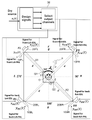
- FIG. 1 is a conceptual diagram showing an acoustic system according to one embodiment of the present invention.
- the sound system according to this embodiment uses the electrodynamic speaker 20 and the super-directional speaker 10, and controls the position of the virtual sound source P from the listener O by the control unit 30.
- the super-directional speaker 10 is a parametric speaker using, for example, ultrasonic waves as carrier waves.
- the electrodynamic speaker 20 is generally used as an audio device, is a dynamic drive system speaker using a permanent magnet and a moving coil, and generally has a low direct-to-direct ratio (reverberation is large with respect to direct sound).
- the electrodynamic speaker 20 and the superdirective speaker 10 are arranged so that the output direction of sound from the electrodynamic speaker 20 and the output direction of sound from the superdirective speaker 10 match.
- a clue (index) for the sense of distance of the virtual sound source P is the direct ratio of the impulse response.
- the control unit 30 controls the super-directional speaker 10 and the electrodynamic speaker 20 so as to output sound corresponding to the input signal.
- the acoustic system has, as electrodynamic speakers 20, a first electrodynamic speaker 20FL, a second electrodynamic speaker 20BR, a third electrodynamic speaker 20FR, and a fourth electrodynamic speaker 20BL.
- the super-directive speaker 10 includes a first super-directive speaker 10FL, a second super-directive speaker 10BR, a third super-directive speaker 10FR and a fourth super-directive speaker 10BL.
- the first electrodynamic speaker 20FL and the first superdirective speaker 10FL are arranged so that the output direction of sound from the first electrodynamic speaker 20FL and the output direction of sound from the first superdirective speaker 10FL match. to place.
- the second electrodynamic speaker 20BR and the second superdirective speaker 10BR are arranged so that the output direction of sound from the second electrodynamic speaker 20BR and the output direction of sound from the second superdirective speaker 10BR match. to place.
- the third electrodynamic speaker 20FR and the third superdirective speaker 10FR are arranged so that the output direction of sound from the third electrodynamic speaker 20FR and the output direction of sound from the third superdirective speaker 10FR match. to place.
- the fourth electrodynamic speaker 20BL and the fourth superdirective speaker 10BL are arranged so that the output direction of sound from the fourth electrodynamic speaker 20BL and the output direction of sound from the fourth superdirective speaker 10BL match. to place.
- a first quadrant F is defined between the first electrodynamic speaker 20FL and the first superdirective speaker 10FL, and the third electrodynamic speaker 20FR and the third superdirective speaker 10FR. do.
- a second quadrant R is defined between the third electrodynamic speaker 20FR and the third super-directional speaker 10FR and the second electro-dynamic speaker 20BR and the second super-directional speaker 10BR with the listener O at the center. do.
- a third quadrant B is defined between the second electrodynamic speaker 20BR and the second super-directional speaker 10BR and the fourth electro-dynamic speaker 20BL and the fourth super-directional speaker 10BL. do.
- a fourth quadrant L is defined between the fourth electrodynamic speaker 20BL and the fourth superdirective speaker 10BL, and the first electrodynamic speaker 20FL and the first superdirective speaker 10FL, with the listener O at the center. do.
- a distance d is set from the listener O to the speakers 10 and 20
- a distance r (0 ⁇ r ⁇ d) is set from the listener O to the virtual sound source P
- a virtual boundary line is set centering on the listener O, and this virtual boundary line
- the virtual sound source is azimuth ⁇ (-45° ⁇ ⁇ ⁇ 315° ).
- si(t) is the signal of the i-th normalized material sound (object), t is time, FL is -45° direction, FR is 45° direction, BL is 225° direction, BR is 135° ° direction, F is 0 ° direction, L is 270 ° direction, R is 90 ° direction, B is 180 ° direction.
- xFL(t) is the output signal from the first electrodynamic speaker 20FL
- xFR(t) is the output signal from the third electrodynamic speaker 20FR
- xBL(t) is the output signal from the fourth electrodynamic speaker 20BL.
- xBR(t) is the output signal from the second electrodynamic speaker 20BR
- yFL(t) is the output signal from the first super-directional speaker 10FL
- yFR(t) is the output signal from the third super-directional speaker 10FR.
- the output signal, yBL(t), is the output signal from the fourth superdirective speaker 10BL
- yBR(t) is the output signal from the second superdirective speaker 10BR.
- the output signal is created by projecting the azimuth ⁇ of the virtual sound source P forward (-45° ⁇ 45°).
- ⁇ F be the direction of the virtual sound source P when the direction of the virtual sound source P is projected forward.
- ⁇ F can be calculated by the following equation.
- FIG. 2 shows a flow chart of signal generation for controlling the virtual sound source P located far from the listener O.
- ⁇ yD1(t) and ⁇ yD2(t) are the signals of the super-directional speaker 10 installed at each position
- ⁇ xD1(t) and ⁇ xD2(t) are the signals of the electrodynamic speaker 20 installed at each position. is a signal.
- ⁇ yD1(t), ⁇ yD2(t), ⁇ xD1(t), and ⁇ xD2(t) can be calculated by the following equations.
- the weighting coefficients ⁇ F, ⁇ F, gL, and gR can be calculated by the following equations.
- FIG. 3 shows a flow chart of signal generation for controlling the virtual sound source P at a short distance of the listener O.
- ⁇ yC1(t), ⁇ yC2(t), ⁇ yC3(t), and ⁇ yC4(t) indicate the signals of the super-directive speaker 10 installed at each position.
- ⁇ yC1(t), ⁇ yC2(t), ⁇ yC3(t), and ⁇ yC4(t) can be calculated by the following equations.
- the weighting coefficients ⁇ F and ⁇ B can be calculated by the following equations.
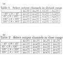
- FIG. 4A is a table showing signal output destinations at a long distance from the listener O
- FIG. 4B is a table showing signal output destinations at a short distance from the listener O.
- FIG. No output is made from the speakers 10 and 20 that have no selection destination.
- different processing is performed depending on whether the listener O is at a short distance or a long distance.
- a virtual sound source P that moves through the listener O is constructed by using the super-directive speaker 10 facing the listener O.
- - ⁇ Rendering of the moving virtual sound source P can be realized by calculating a weighting factor from the position (moving speed and time) of the virtual sound source P and changing it.
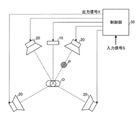
- FIG. 5 is a diagram showing an integrated loudspeaker suitable for the sound system according to this embodiment.
- the electrodynamic loudspeaker 20 and the super-directional loudspeaker 10 are arranged in one housing 40 .
- the electrodynamic speaker 20 and the super-directional speaker 10 are formed into an integrated speaker in this way, the output direction of the sound from the electro-dynamic speaker 20 and the output direction of the sound from the super-directive speaker 10 are different. easy to match.
- FIG. 5 shows the configuration in which the super-directional speaker 10 and the electrodynamic speaker 20 are arranged in the vertical direction, they may be arranged in the horizontal direction.
- a plurality of ultrasonic wave generating elements are arranged in an array vertically and horizontally.
- An audible range can be set by arranging a plurality of ultrasonic wave generating elements in an array.
- the first electrodynamic speaker 20FL and the first superdirective speaker 10FL are arranged in one housing 40 (first housing) to form an integrated speaker, and the second electrodynamic speaker 20BR and the second superdirective speaker are arranged.
- the dynamic speaker 10BR is arranged in one housing 40 (second housing) as an integrated speaker, and the third electrodynamic speaker 20FR and the third super-directional speaker 10FR are arranged in one housing 40 (second housing).
- the fourth electrodynamic speaker 20BL and the fourth super-directional speaker 10BL are arranged in one housing (second housing) as an integrated speaker. preferably.
- the output direction of sound from the first electro-dynamic speaker 20FL and the first super-directional speaker 10FL It is easy to match the output direction of the sound from 10FL
- the second electrodynamic speaker 20BR and the second super-directional speaker 10BR into an integrated speaker
- the output of the sound from the second electrodynamic speaker 20BR It is easy to match the output direction of the sound from the second super-directional speaker 10BR with the output direction of the sound from the second super-directional speaker 10BR.
- the output direction of sound from the electrodynamic speaker 20FR and the output direction of sound from the third super-directional speaker 10FR are easily matched, and the fourth electrodynamic speaker 20BL and the fourth super-directional speaker 10BL are integrated.
- the control unit 30 when the virtual sound source P is outside the listener (distant) from the virtual boundary line, the control unit 30 generates an impulse response from the first electrodynamic speaker 20FL to the listener O, changing the energy ratio of the impulse response from the first super-directional speaker 10FL to the listener O to control the first far-distance direct ratio, and the impulse response from the third electrodynamic speaker 20FR to the listener O;
- the first far-field output sound set by the first far-field direct ratio is controlled by changing the energy ratio with the impulse response from the third super-directional speaker 10FR to the listener O and the third far-field output sound set by the third far-field direct ratio by amplitude panning to change the azimuth and distance of the virtual sound source P from the listener O.
- the control unit 30 controls the first super-directional speaker 10FL and the second super-directional speaker 10FL.
- the first short-range level difference is controlled by changing the energy ratio with 10BR
- the third short-range level difference is controlled by changing the energy ratio between the third super-directional speaker 10FR and the fourth super-directional speaker 10BL.
- the first short-distance output sound set by the first near-distance level difference and the third near-distance output sound set by the third near-distance level difference are controlled by amplitude panning, so that the listener O The azimuth and distance of the virtual sound source P are changed.
- the control unit 30 controls the impulse response from the third electrodynamic speaker 20FR to the listener O and the energy ratio of the impulse response from the third super-directional speaker 10FR to the listener O is changed to control the third far-distance direct ratio, and the impulse response from the second electrodynamic speaker 20BR to the listener O and the impulse response from the second super-directional speaker 10BR to the listener O to control the second long-distance direct ratio, and the third far-distance direct ratio set by the third far-distance direct ratio
- the azimuth and distance of the virtual sound source P from the listener O are changed by controlling the output sound and the second far-distance output sound set by the second far-distance direct ratio by amplitude panning.
- the control unit 30 controls the third super-directional speaker 10FR and the fourth super-directional speaker 10BL is changed to control the third short-range level difference, and the energy ratio of the second super-directional speaker 10BR and the first super-directional speaker 10FL is changed to control the second short-range level difference.
- the third short-distance output sound set by the third near-distance level difference and the second near-distance output sound set by the second near-distance level difference are controlled by amplitude panning, so that the listener O The azimuth and distance of the virtual sound source P are changed.
- the control unit 30 controls the impulse response from the second electrodynamic speaker 20BR to the listener O , the energy ratio of the impulse response from the second super-directional speaker 10BR to the listener O is changed to control the second long-distance direct ratio, and the impulse response from the fourth electrodynamic speaker 20BL to the listener O and the impulse response from the fourth super-directional speaker 10BL to the listener O to control the fourth long-distance direct ratio, and the second long-distance direct ratio set by the second far-distance direct ratio
- the azimuth and distance of the virtual sound source P from the listener O are changed by controlling the output sound and the fourth far-distance output sound set by the fourth far-distance direct ratio by amplitude panning.
- the control unit 30 controls the second super-directional speaker 10BR and the first super-directional speaker 10BR. 10FL to control the second short-range level difference, and by changing the energy ratios of the fourth super-directional speaker 10BL and the third super-directional speaker 10FR to control the fourth short-range level difference.
- the second short-distance output sound set by the second near-distance level difference and the fourth near-distance output sound set by the fourth near-distance level difference are controlled by amplitude panning, so that the listener O The azimuth and distance of the virtual sound source P are changed.
- the control unit 30 controls the impulse response from the fourth electrodynamic speaker 20BL to the listener O. and the impulse response from the fourth super-directional speaker 10BL to the listener O is changed to control the fourth long-distance direct ratio, and the impulse response from the first electrodynamic speaker 20FL to the listener O and the impulse response from the first super-directional speaker 10FL to the listener O to control the first far distance direct ratio, and the fourth far distance set by the fourth far distance direct ratio
- the azimuth and distance of the virtual sound source P from the listener O are changed by controlling the output sound and the first far-distance output sound set by the first far-distance direct ratio by amplitude panning.
- the control unit 30 controls the fourth super-directional speaker 10BL and the third super-directional speaker 10BL.
- the fourth short-range level difference is controlled by changing the energy ratio with 10FR
- the first short-range level difference is controlled by changing the energy ratio between the first super-directional speaker 10FL and the second super-directional speaker 10BR.
- the fourth near-field output sound set by the fourth near-field level difference and the first near-field output sound set by the first near-field level difference are controlled by amplitude panning, so that The azimuth and distance of the virtual sound source P are changed.
- the sense of distance to the virtual sound source P can be zoomed in and out in all directions of 360 degrees centered on the listener O, and can be controlled by amplitude panning.
- a sense of remote presence can be given to the listener O, and a moving sound that penetrates the listener O can be given to the listener O in any direction.
- the control unit 30 determines that when the virtual sound source P is outside the listener from the virtual boundary line, the electrodynamic speaker 20 and the super-directional speaker 10 to control the direct ratio of the impulse response to express the perspective of the sound, and when the virtual sound source P is inside the listener from the virtual boundary line, the amplitude panning of the super-directional speaker 10
- the control unit 30 determines that when the virtual sound source P is outside the listener from the virtual boundary line, the electrodynamic speaker 20 and the super-directional speaker 10 to control the direct ratio of the impulse response to express the perspective of the sound, and when the virtual sound source P is inside the listener from the virtual boundary line, the amplitude panning of the super-directional speaker 10
- amplitude panning is performed by combining the electrodynamic speaker 20 with a low direct-to-direct ratio of the impulse response and the parametric speaker with a high direct-to-direct ratio of the impulse response. be able to. Therefore, the direct ratio of the impulse response at the position of the listener O, which is a clue for the sense of distance of the virtual sound source P, can be controlled with higher accuracy.
- the electrodynamic speaker 20 includes the first electrodynamic speaker 20FL, the second electrodynamic speaker 20BR, the third electrodynamic speaker 20FR, and the fourth electrodynamic speaker 20BL.
- the directional speaker 10 includes the first super-directional speaker 10FL, the second super-directional speaker 10BR, the third super-directional speaker 10FR, and the fourth super-directional speaker 10BL
- the electrodynamic speaker 20 includes a first electrodynamic speaker 20FL and a second electrodynamic speaker 20BR
- the superdirective speaker 10 includes a first superdirective speaker 10FL and a second superdirective speaker 10BR.
- a first virtual boundary point Q1 is set between the first electrodynamic speaker 20FL and the first superdirective speaker 10FL and the listener O, and the first electrodynamic speaker 20FL and the first superdirective speaker
- a first far distance X1 is defined between the dynamic speaker 10FL and the first imaginary boundary point Q1
- a first short distance Y1 is defined between the first imaginary boundary point Q1 and the listener O
- a second virtual boundary point Q2 is set between the super-directional speaker 10BR and the listener O, and the second electrodynamic speaker 20BR and the second super-directional speaker 10BR are separated from the second virtual boundary point Q2.
- the controller 30 performs the following control. That is, when there is a virtual sound source P at the first long distance X1, the control unit 30 generates an impulse response from the first electrodynamic speaker 20FL to the listener O, and an impulse response from the first super-directional speaker 10FL to the listener O.
- the energy ratio with the impulse response is changed to control the first far distance direct ratio, and when there is a virtual sound source P in the first short distance Y1, the first super directional speaker 10FL and the second super directional speaker 10BR
- the energy ratio of the impulse response from the super-directional speaker 10BR to the listener O is changed to control the second long-distance direct ratio, and when the virtual sound source P is in the second short-distance Y2, the second super-directivity
- the second close-range level difference is controlled by changing the energy ratio between the speaker 10BR and the first super-directional speaker 10FL.
- the sense of distance to the virtual sound source P can be zoomed in or out, giving the listener O a sense of remote presence.
- the listener O can be given a moving sound that is transmitted through the listener O.
- the electrodynamic speaker 20 includes the first electrodynamic speaker 20FL and the second electrodynamic speaker 20BR
- the superdirective speaker 10 includes the first superdirective speaker 10FL and the superdirective speaker 10FL.
- the electro-dynamic speaker 20 has the third electro-dynamic speaker 20FR and the fourth electro-dynamic speaker 20BL, and the super-directional speaker 10 , a third super-directional speaker 10FR and a fourth super-directional speaker 10BL.
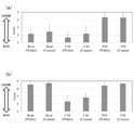
- FIG. 6 is a graph showing a correspondence table of the moving direction of the moving sound image and the front direction of the head direction.
- the MOS Komori et al., Theory of IEICE (A), J99-A(11), 426-429, 2016] with a 5-point scale was used to evaluate the sense of movement and localization in the head.
- the evaluation of the feeling of movement is as follows: (5: Moving smoothly, 4: Moving with some discomfort, 3: Moving with discomfort, 2: Not moving much, 1: Moving ), and the feeling of localization in the head was evaluated as follows: (5: Clearly localized in the head; 2: not very localized in the head; 1: not localized in the head).
- FIG. 7 is a graph showing experimental results.
- Real(White) is the result of manually moving the speaker (white noise)
- Real(Canon) is the result of manually moving the speaker (canon)
- CM(White) is the result of a comparative example (white noise)
- CM (Canon) indicates the result of the comparative example (Canon)
- PM(White) indicates the result of the example (white noise)
- PM(Canon) indicates the result of the example (Canon).
- FIG. 7(a) shows the score of the sense of movement
- FIG. 7(b) shows the score of the sense of localization in the head.
- both Real and PM had a smooth movement feeling compared to CM.
- FIG. 7(a) both Real and PM had a smooth movement feeling compared to CM.
Abstract
本発明は、前記第1動電型スピーカ20FL及び前記第1超指向性スピーカ10FLからの前記音の第1出力方向と、前記第2動電型スピーカ20BR及び前記第2超指向性スピーカ10BRからの前記音の第2出力方向とを、対向させて前記受聴者Oの位置に向け、制御部30は、前記第1近距離Y1及び前記第2近距離Y2に前記仮想音源Pがあるときは、前記第1超指向性スピーカ10FLと、前記第2超指向性スピーカ10BRとのエネルギー比を変えて第1近距離レベル差及び第2近距離レベル差を制御することで、受聴者Oを透過する移動音を提示することができる音響システムを提供する。
Description
本発明は、動電型スピーカと超指向性スピーカとを用い、受聴者からの仮想音源の位置を制御する音響システムに関する。
マルチチャネル立体音響システムにおけるオブジェクトベース方式では、スピーカ間に仮想音源を構築するために、ベクトル合成(非特許文献1)に基づく音圧により制御しているが、スピーカ・受聴者間に仮想音源を構築することは極めて困難であった。しかしながら、音のバーチャルリアリティを実現するためには、受聴者への音の到来方位だけではなく、受聴者から仮想音源までの距離の制御が非常に重要な要素となる。頭部伝達関数を用いて仮想音源を提供するバイノーラル方式(非特許文献2)は頭部近傍の音源定位には有用であるが、仮想音源を遠方に構築することが難しい。超高臨場感通信技術(非特許文献3)のように非常に多数のスピーカを用いて、仮想音源を任意の位置に構築する手法も検討されているが、コンサート会場のような大規模な設備を必要とする。
本発明者は、これまでに、超指向性スピーカと動電型スピーカの出力レベルを制御することで、仮想音源を任意の位置に制御する方法を提案している(特許文献1)。
図9は、特許文献1で開示する音響システムの構成図である。
図9に示す音響システムは、1つのパラメトリックスピーカ10と、4つの動電型スピーカ20と、制御部30とを備える。
パラメトリックスピーカ10は、受聴者Oに対して正面に配置する。4つの動電型スピーカ20は、それぞれ、受聴者Oに対して、前方左側、前方右側、後方左側、および、後方右側に配置する。
制御部30は、音声信号である入力信号Sに基づいて、入力信号Sに対応する音を出力するように、パラメトリックスピーカ10および4つの動電型スピーカ20を制御する。
特許文献2には、動電型スピーカにより形成される可聴音のスピーカ音場と、超指向性スピーカにより形成される可聴音の超指向性スピーカ音場とが受聴者の位置で重なるように、動電型スピーカと超指向性スピーカとを配置した音響再生装置が開示されている。
特許文献2では、動電型スピーカと超指向性スピーカとから放射された可聴音が、それぞれのスピーカが設置された位置から音軸方向の所定の距離dkに受聴者が位置した時に最も大きく聴こえ、受聴者が所定の距離dkから外れると小さくなる。従って、特許文献2は、受聴者の周りに多くの動電型スピーカを配置することなく、受聴者に対して一つの同じ方向に設置された動電型スピーカと超指向性スピーカのみで、受聴者の近傍に可聴音の最大音圧を作り、受聴者に対して、音で囲まれていると感じさせる立体的な音場を実現する。
Lopez,他3名,Sound distance perception comparison between Wave Field Synthesis and Vector Base Amplitude Panning,ISCCSP, 2014年,p165-168
Zhou他, APSIPA ASC 2014年, p1-4
堤公孝,高田英明著,客席まで飛び出す音響を実現する波面合成音響技術」,NTT技術ジャーナル,2017年,Vol.29,No.10,p.24-28
本発明は、小規模な音響システムで受聴者と仮想音源間の方位と距離の両方を制御するために、超音波を利用した超指向性スピーカであるパラメトリックスピーカ(Parametric-Array Loudspeaker: PAL)に着目する。
図8(a)、図8(b)に、それぞれスピーカ・受音点間距離2mの条件における、動電型スピーカ(Electro-Dynamic Loudspeaker: EDL)の室内インパルス応答と、超指向性スピーカであるパラメトリックスピーカの室内インパルス応答とを示す。
図8に示すように、従来の動電型スピーカ(EDL)とパラメトリックスピーカ(PAL)とでは、同条件における室内インパルス応答の後続残響が大きく異なることがわかる。これは、超指向性スピーカが空気の非線形性を利用して空中で2次波として可聴音を復調させることに起因する。室内インパルス応答の直接波に対する残響の比率である直間比(Direct-to-Reverberant Ratio: DRR)は、人が知覚する音像距離感の手がかりであり、高DRRとなる超指向性スピーカは頭部近傍に音像が定位しやすい。
特許文献1は、サラウンド配置した動電型スピーカに加えて、超指向性スピーカを正面に設置することで、仮想音源の距離を制御している。しかし、超指向性スピーカを正面に配置した場合、両耳間レベル差(Interaural Level Difference: ILD)が劣化することで、方位の提示性能が低下する傾向がある。
特許文献2は、動電型スピーカと超指向性スピーカとを並置しているが、音で囲まれていると感じさせる立体的な音場を実現するものであり、受聴者から仮想音源までの距離を変更するものではない。
本発明者は、特許文献1の課題に対して、動電型スピーカからの音の出力方向と、超指向性スピーカからの音の出力方向とが一致するように、動電型スピーカと超指向性スピーカとを配置し、動電型スピーカから受聴者までのインパルス応答と、超指向性スピーカから受聴者までのインパルス応答とのエネルギー比を変えて直間比を制御することで、受聴者と仮想音源との距離を変化させ、仮想音源までの距離感を、いわゆるズームインやズームアウトでき、受聴者に対して遠隔臨場感を与えることができる音響システムを新たに発明している。
しかし、この新たな音響システムでは、受聴者から所定距離以上離れた仮想音源に対しては、実音源の実際の配置と変わらない遠隔臨場感を与えることができるが、受聴者に極めて近い近距離音場では音像の提示性能が劣化する傾向があり、特に受聴者を透過する移動音を提示するには至っていない。
そこで本発明は、受聴者を透過する移動音を提示することができる音響システムを提供することを目的とする。
請求項1記載の本発明の音響システムは、動電型スピーカ20と超指向性スピーカ10とを用い、受聴者Oからの仮想音源Pの位置を制御部30で制御する音響システムであって、前記動電型スピーカ20として、少なくとも第1動電型スピーカ20FLと第2動電型スピーカ20BRとを有し、前記超指向性スピーカ10として、少なくとも第1超指向性スピーカ10FLと第2超指向性スピーカ10BRとを有し、前記第1動電型スピーカ20FLからの音の出力方向と、前記第1超指向性スピーカ10FLからの音の出力方向とが一致するように、前記第1動電型スピーカ20FLと前記第1超指向性スピーカ10FLとを配置し、前記第2動電型スピーカ20BRからの音の出力方向と、前記第2超指向性スピーカ10BRからの音の出力方向とが一致するように、前記第2動電型スピーカ20BRと前記第2超指向性スピーカ10BRとを配置し、前記第1動電型スピーカ20FL及び前記第1超指向性スピーカ10FLからの前記音の第1出力方向と、前記第2動電型スピーカ20BR及び前記第2超指向性スピーカ10BRからの前記音の第2出力方向とを、対向させて前記受聴者Oの位置に向け、前記第1動電型スピーカ20FL及び前記第1超指向性スピーカ10FLと前記受聴者Oとの間に第1仮想境界点Q1を設定し、前記第1動電型スピーカ20FL及び前記第1超指向性スピーカ10FLと前記第1仮想境界点Q1との間を第1遠距離X1、前記第1仮想境界点Q1と前記受聴者Oとの間を第1近距離Y1とし、前記第2動電型スピーカ20BR及び前記第2超指向性スピーカ10BRと前記受聴者Oとの間に第2仮想境界点Q2を設定し、前記第2動電型スピーカ20BR及び前記第2超指向性スピーカ10BRと前記第2仮想境界点Q2との間を第2遠距離X2、前記第2仮想境界点Q2と前記受聴者Oとの間を第2近距離Y2としたとき、前記制御部30は、前記第1遠距離X1に前記仮想音源Pがあるときは、前記第1動電型スピーカ20FLから前記受聴者Oまでのインパルス応答と、前記第1超指向性スピーカ10FLから前記受聴者Oまでのインパルス応答とのエネルギー比を変えて第1遠距離直間比を制御し、前記第2遠距離X2に前記仮想音源Pがあるときは、前記第2動電型スピーカ20BRから前記受聴者Oまでのインパルス応答と、前記第2超指向性スピーカ10BRから前記受聴者Oまでのインパルス応答とのエネルギー比を変えて第2遠距離直間比を制御し、前記第1近距離Y1及び前記第2近距離Y2に前記仮想音源Pがあるときは、前記第1超指向性スピーカ10FLと、前記第2超指向性スピーカ10BRとのエネルギー比を変えて第1近距離レベル差及び第2近距離レベル差を制御することを特徴とする。
請求項2記載の本発明は、請求項1に記載の音響システムにおいて、前記第1動電型スピーカ20FLと前記第1超指向性スピーカ10FLとを第1筐体40に配置し、前記第2動電型スピーカ20BRと前記第2超指向性スピーカ10BRとを第2筐体40に配置することを特徴とする。
請求項3記載の本発明の音響システムは、動電型スピーカ20と超指向性スピーカ10とを用い、受聴者Oからの仮想音源Pの位置を制御部30で制御する音響システムであって、前記動電型スピーカ20として、少なくとも第1動電型スピーカ20FLと第2動電型スピーカ20BRと第3動電型スピーカ20FRと第4動電型スピーカ20BLとを有し、前記超指向性スピーカ10として、少なくとも第1超指向性スピーカ10FLと第2超指向性スピーカ10BRと第3超指向性スピーカ10FRと第4超指向性スピーカ10BLとを有し、前記第1動電型スピーカ20FLからの音の出力方向と、前記第1超指向性スピーカ10FLからの音の出力方向とが一致するように、前記第1動電型スピーカ20FLと前記第1超指向性スピーカ10FLとを配置し、前記第2動電型スピーカ20BRからの音の出力方向と、前記第2超指向性スピーカ10BRからの音の出力方向とが一致するように、前記第2動電型スピーカ20BRと前記第2超指向性スピーカ10BRとを配置し、前記第3動電型スピーカ20FRからの音の出力方向と、前記第3超指向性スピーカ10FRからの音の出力方向とが一致するように、前記第3動電型スピーカ20FRと前記第3超指向性スピーカ10FRとを配置し、前記第4動電型スピーカ20BLからの音の出力方向と、前記第4超指向性スピーカ10BLからの音の出力方向とが一致するように、前記第4動電型スピーカ20BLと前記第4超指向性スピーカ10BLとを配置し、前記第1動電型スピーカ20FL及び前記第1超指向性スピーカ10FLからの前記音の第1出力方向と、前記第2動電型スピーカ20BR及び前記第2超指向性スピーカ10BRからの前記音の第2出力方向とを、対向させて前記受聴者Oの位置に向け、前記第3動電型スピーカ20FR及び前記第3超指向性スピーカ10FRからの前記音の第3出力方向と、前記第4動電型スピーカ20BL及び前記第4超指向性スピーカ10BLからの前記音の第4出力方向とを、対向させて前記受聴者Oの位置に向け、前記第1動電型スピーカ20FL及び前記第1超指向性スピーカ10FLと前記第2動電型スピーカ20BR及び前記第2超指向性スピーカ10BRとを結ぶ第1仮想線と、前記第3動電型スピーカ20FR及び前記第3超指向性スピーカ10FRと前記第4動電型スピーカ20BL及び前記第4超指向性スピーカ10BLとを結ぶ第2仮想線とを交差させ、前記受聴者Oを中心として、前記第1動電型スピーカ20FL及び前記第1超指向性スピーカ10FLと、前記第3動電型スピーカ20FR及び前記第3超指向性スピーカ10FRとの間を第1象限Fとし、前記受聴者Oを中心として、前記第3動電型スピーカ20FR及び前記第3超指向性スピーカ10FRと、前記第2動電型スピーカ20BR及び前記第2超指向性スピーカ10BRとの間を第2象限Rとし、前記受聴者Oを中心として、前記第2動電型スピーカ20BR及び前記第2超指向性スピーカ10BRと、前記第4動電型スピーカ20BL及び前記第4超指向性スピーカ10BLとの間を第3象限Bとし、前記受聴者Oを中心として、前記第4動電型スピーカ20BL及び前記第4超指向性スピーカ10BLと、前記第1動電型スピーカ20FL及び前記第1超指向性スピーカ10FLとの間を第4象限Lとし、前記受聴者Oを中心とした仮想境界線を設定したとき、前記制御部30は、前記第1象限Fで、前記仮想境界線よりも受聴者外方に前記仮想音源Pがあるときは、前記第1動電型スピーカ20FLから前記受聴者Oまでのインパルス応答と、前記第1超指向性スピーカ10FLから前記受聴者Oまでのインパルス応答とのエネルギー比を変えて第1遠距離直間比を制御し、前記第3動電型スピーカ20FRから前記受聴者Oまでのインパルス応答と、前記第3超指向性スピーカ10FRから前記受聴者Oまでのインパルス応答とのエネルギー比を変えて第3遠距離直間比を制御し、前記第1遠距離直間比によって設定される第1遠距離出力音と、前記第3遠距離直間比によって設定される第3遠距離出力音とを振幅パンニングにより制御することで、前記受聴者Oからの前記仮想音源Pの方位と距離とを変更し、前記第2象限Rで、前記仮想境界線よりも受聴者外方に前記仮想音源Pがあるときは、前記第3動電型スピーカ20FRから前記受聴者Oまでのインパルス応答と、前記第3超指向性スピーカ10FRから前記受聴者Oまでのインパルス応答とのエネルギー比を変えて第3遠距離直間比を制御し、前記第2動電型スピーカ20BRから前記受聴者Oまでのインパルス応答と、前記第2超指向性スピーカ10BRから前記受聴者Oまでのインパルス応答とのエネルギー比を変えて第2遠距離直間比を制御し、前記第3遠距離直間比によって設定される第3遠距離出力音と、前記第2遠距離直間比によって設定される第2遠距離出力音とを振幅パンニングにより制御することで、前記受聴者Oからの前記仮想音源Pの方位と距離とを変更し、前記第3象限Bで、前記仮想境界線よりも受聴者外方に前記仮想音源Pがあるときは、前記第2動電型スピーカ20BRから前記受聴者Oまでのインパルス応答と、前記第2超指向性スピーカ10BRから前記受聴者Oまでのインパルス応答とのエネルギー比を変えて第2遠距離直間比を制御し、前記第4動電型スピーカ20BLから前記受聴者Oまでのインパルス応答と、前記第4超指向性スピーカ10BLから前記受聴者Oまでのインパルス応答とのエネルギー比を変えて第4遠距離直間比を制御し、前記第2遠距離直間比によって設定される第2遠距離出力音と、前記第4遠距離直間比によって設定される第4遠距離出力音とを振幅パンニングにより制御することで、前記受聴者Oからの前記仮想音源Pの方位と距離とを変更し、前記第4象限Lで、前記仮想境界線よりも受聴者外方に前記仮想音源Pがあるときは、前記第4動電型スピーカ20BLから前記受聴者Oまでのインパルス応答と、前記第4超指向性スピーカ10BLから前記受聴者Oまでのインパルス応答とのエネルギー比を変えて第4遠距離直間比を制御し、前記第1動電型スピーカ20FLから前記受聴者Oまでのインパルス応答と、前記第1超指向性スピーカ10FLから前記受聴者Oまでのインパルス応答とのエネルギー比を変えて第1遠距離直間比を制御し、前記第4遠距離直間比によって設定される第4遠距離出力音と、前記第1遠距離直間比によって設定される第1遠距離出力音とを振幅パンニングにより制御することで、前記受聴者Oからの前記仮想音源Pの方位と距離とを変更し、前記第1象限Fで、前記仮想境界線よりも受聴者内方に前記仮想音源Pがあるときは、前記第1超指向性スピーカ10FLと、前記第2超指向性スピーカ10BRとのエネルギー比を変えて第1近距離レベル差を制御し、前記第3超指向性スピーカ10FRと、前記第4超指向性スピーカ10BLとのエネルギー比を変えて第3近距離レベル差を制御し、前記第1近距離レベル差によって設定される第1近距離出力音と、前記第3近距離レベル差によって設定される第3近距離出力音とを振幅パンニングにより制御することで、前記受聴者Oからの前記仮想音源Pの方位と距離とを変更し、前記第2象限Rで、前記仮想境界線よりも受聴者内方に前記仮想音源Pがあるときは、前記第3超指向性スピーカ10FRと、前記第4超指向性スピーカ10BLとのエネルギー比を変えて第3近距離レベル差を制御し、前記第2超指向性スピーカ10BRと、前記第1超指向性スピーカ10FLとのエネルギー比を変えて第2近距離レベル差を制御し、前記第3近距離レベル差によって設定される第3近距離出力音と、前記第2近距離レベル差によって設定される第2近距離出力音とを振幅パンニングにより制御することで、前記受聴者Oからの前記仮想音源Pの方位と距離とを変更し、前記第3象限Bで、前記仮想境界線よりも受聴者内方に前記仮想音源Pがあるときは、前記第2超指向性スピーカ10BRと、前記第1超指向性スピーカ10FLとのエネルギー比を変えて第2近距離レベル差を制御し、前記第4超指向性スピーカ10BLと、前記第3超指向性スピーカ10FRとのエネルギー比を変えて第4近距離レベル差を制御し、前記第2近距離レベル差によって設定される第2近距離出力音と、前記第4近距離レベル差によって設定される第4近距離出力音とを振幅パンニングにより制御することで、前記受聴者Oからの前記仮想音源Pの方位と距離とを変更し、前記第4象限Lで、前記仮想境界線よりも受聴者内方に前記仮想音源Pがあるときは、前記第4超指向性スピーカ10BLと、前記第3超指向性スピーカ10FRとのエネルギー比を変えて第4近距離レベル差を制御し、前記第1超指向性スピーカ10FLと、前記第2超指向性スピーカ10BRとのエネルギー比を変えて第1近距離レベル差を制御し、前記第4近距離レベル差によって設定される第4近距離出力音と、前記第1近距離レベル差によって設定される第1近距離出力音とを振幅パンニングにより制御することで、前記受聴者Oからの前記仮想音源Pの方位と距離とを変更することを特徴とする。
請求項4記載の本発明の音響システムは、複数の動電型スピーカ20と複数の超指向性スピーカ10とを用い、受聴者Oからの仮想音源Pの位置を制御部30で制御する音響システムであって、前記受聴Oを中心とした仮想境界線を設定したとき、前記制御部30は、前記仮想境界線よりも受聴者外方に前記仮想音源Pがあるときは、前記動電型スピーカ20と前記超指向性スピーカ10との振幅パンニングによりインパルス応答の直間比を制御して音の遠近感を表現し、前記仮想境界線よりも受聴者内方に前記仮想音源Pがあるときは、前記超指向性スピーカ10の振幅パンニングにより両耳間レベル差を制御して頭内定位を表現することを特徴とする。
請求項5記載の本発明は、請求項3又は請求項4に記載の音響システムにおいて、前記動電型スピーカ20と前記超指向性スピーカ10とを一つの筐体40に配置することを特徴とする。
請求項6記載の本発明は、請求項1から請求項5のいずれか1項に記載の音響システムにおいて、前記超指向性スピーカ10として、パラメトリックスピーカを用いることを特徴とする。
本発明によれば、受聴者と仮想音源との距離を変化させることで、受聴者に対して遠隔臨場感を与えることができるとともに、受聴者を透過する移動音を受聴者に与えることができる。
本発明の第1の実施の形態による音響システムは、動電型スピーカとして、少なくとも第1動電型スピーカと第2動電型スピーカとを有し、超指向性スピーカとして、少なくとも第1超指向性スピーカと第2超指向性スピーカとを有し、第1動電型スピーカからの音の出力方向と、第1超指向性スピーカからの音の出力方向とが一致するように、第1動電型スピーカと第1超指向性スピーカとを配置し、第2動電型スピーカからの音の出力方向と、第2超指向性スピーカからの音の出力方向とが一致するように、第2動電型スピーカと第2超指向性スピーカとを配置し、第1動電型スピーカ及び第1超指向性スピーカからの音の第1出力方向と、第2動電型スピーカ及び第2超指向性スピーカからの音の第2出力方向とを、対向させて受聴者の位置に向け、第1動電型スピーカ及び第1超指向性スピーカと受聴者との間に第1仮想境界点を設定し、第1動電型スピーカ及び第1超指向性スピーカと第1仮想境界点との間を第1遠距離、第1仮想境界点と受聴者との間を第1近距離とし、第2動電型スピーカ及び第2超指向性スピーカと受聴者との間に第2仮想境界点を設定し、第2動電型スピーカ及び第2超指向性スピーカと第2仮想境界点との間を第2遠距離、第2仮想境界点と受聴者との間を第2近距離としたとき、制御部は、第1遠距離に仮想音源があるときは、第1動電型スピーカから受聴者までのインパルス応答と、第1超指向性スピーカから受聴者までのインパルス応答とのエネルギー比を変えて第1遠距離直間比を制御し、第2遠距離に仮想音源があるときは、第2動電型スピーカから受聴者までのインパルス応答と、第2超指向性スピーカから受聴者までのインパルス応答とのエネルギー比を変えて第2遠距離直間比を制御し、第1近距離及び第2近距離に仮想音源があるときは、第1超指向性スピーカと、第2超指向性スピーカとのエネルギー比を変えて第1近距離レベル差及び第2近距離レベル差を制御するものである。
本実施の形態によれば、受聴者と仮想音源との距離を変化させることで、仮想音源までの距離感を、いわゆるズームインやズームアウトでき、受聴者に対して遠隔臨場感を与えることができるとともに、受聴者を透過する移動音を受聴者に与えることができる。
本実施の形態によれば、受聴者と仮想音源との距離を変化させることで、仮想音源までの距離感を、いわゆるズームインやズームアウトでき、受聴者に対して遠隔臨場感を与えることができるとともに、受聴者を透過する移動音を受聴者に与えることができる。
本発明の第2の実施の形態は、第1の実施の形態による音響システムにおいて、第1動電型スピーカと第1超指向性スピーカとを第1筐体に配置し、第2動電型スピーカと第2超指向性スピーカとを第2筐体に配置するものである。
本実施の形態によれば、動電型スピーカと超指向性スピーカとを一体型スピーカとすることで、動電型スピーカからの音の出力方向と、超指向性スピーカからの音の出力方向とを一致させやすい。
本実施の形態によれば、動電型スピーカと超指向性スピーカとを一体型スピーカとすることで、動電型スピーカからの音の出力方向と、超指向性スピーカからの音の出力方向とを一致させやすい。
本発明の第3の実施の形態による音響システムは、動電型スピーカとして、少なくとも第1動電型スピーカと第2動電型スピーカと第3動電型スピーカと第4動電型スピーカとを有し、超指向性スピーカとして、少なくとも第1超指向性スピーカと第2超指向性スピーカと第3超指向性スピーカと第4超指向性スピーカとを有し、第1動電型スピーカからの音の出力方向と、第1超指向性スピーカからの音の出力方向とが一致するように、第1動電型スピーカと第1超指向性スピーカとを配置し、第2動電型スピーカからの音の出力方向と、第2超指向性スピーカからの音の出力方向とが一致するように、第2動電型スピーカと第2超指向性スピーカとを配置し、第3動電型スピーカからの音の出力方向と、第3超指向性スピーカからの音の出力方向とが一致するように、第3動電型スピーカと第3超指向性スピーカとを配置し、第4動電型スピーカからの音の出力方向と、第4超指向性スピーカからの音の出力方向とが一致するように、第4動電型スピーカと第4超指向性スピーカとを配置し、第1動電型スピーカ及び第1超指向性スピーカからの音の第1出力方向と、第2動電型スピーカ及び第2超指向性スピーカからの音の第2出力方向とを、対向させて受聴者の位置に向け、第3動電型スピーカ及び第3超指向性スピーカからの音の第3出力方向と、第4動電型スピーカ及び第4超指向性スピーカからの音の第4出力方向とを、対向させて受聴者の位置に向け、第1動電型スピーカ及び第1超指向性スピーカと第2動電型スピーカ及び第2超指向性スピーカとを結ぶ第1仮想線と、第3動電型スピーカ及び第3超指向性スピーカと第4動電型スピーカ及び第4超指向性スピーカとを結ぶ第2仮想線とを交差させ、受聴者を中心として、第1動電型スピーカ及び第1超指向性スピーカと、第3動電型スピーカ及び第3超指向性スピーカとの間を第1象限とし、受聴者を中心として、第3動電型スピーカ及び第3超指向性スピーカと、第2動電型スピーカ及び第2超指向性スピーカとの間を第2象限とし、受聴者を中心として、第2動電型スピーカ及び第2超指向性スピーカと、第4動電型スピーカ及び第4超指向性スピーカとの間を第3象限とし、受聴者を中心として、第4動電型スピーカ及び第4超指向性スピーカと、第1動電型スピーカ及び第1超指向性スピーカとの間を第4象限とし、受聴者を中心とした仮想境界線を設定したとき、制御部は、1象限で、仮想境界線よりも受聴者外方に仮想音源があるときは、第1動電型スピーカから受聴者までのインパルス応答と、第1超指向性スピーカから受聴者までのインパルス応答とのエネルギー比を変えて第1遠距離直間比を制御し、第3動電型スピーカから受聴者までのインパルス応答と、第3超指向性スピーカから受聴者までのインパルス応答とのエネルギー比を変えて第3遠距離直間比を制御し、第1遠距離直間比によって設定される第1遠距離出力音と、第3遠距離直間比によって設定される第3遠距離出力音とを振幅パンニングにより制御することで、受聴者からの仮想音源の方位と距離とを変更し、第2象限で、仮想境界線よりも受聴者外方に仮想音源があるときは、第3動電型スピーカから受聴者までのインパルス応答と、第3超指向性スピーカから受聴者までのインパルス応答とのエネルギー比を変えて第3遠距離直間比を制御し、第2動電型スピーカから受聴者までのインパルス応答と、第2超指向性スピーカから受聴者までのインパルス応答とのエネルギー比を変えて第2遠距離直間比を制御し、第3遠距離直間比によって設定される第3遠距離出力音と、第2遠距離直間比によって設定される第2遠距離出力音とを振幅パンニングにより制御することで、受聴者からの仮想音源の方位と距離とを変更し、第3象限で、仮想境界線よりも受聴者外方に仮想音源があるときは、第2動電型スピーカから受聴者までのインパルス応答と、第2超指向性スピーカから受聴者までのインパルス応答とのエネルギー比を変えて第2遠距離直間比を制御し、第4動電型スピーカから受聴者までのインパルス応答と、第4超指向性スピーカから受聴者までのインパルス応答とのエネルギー比を変えて第4遠距離直間比を制御し、第2遠距離直間比によって設定される第2遠距離出力音と、第4遠距離直間比によって設定される第4遠距離出力音とを振幅パンニングにより制御することで、受聴者からの仮想音源の方位と距離とを変更し、第4象限で、仮想境界線よりも受聴者外方に仮想音源があるときは、第4動電型スピーカから受聴者までのインパルス応答と、第4超指向性スピーカから受聴者までのインパルス応答とのエネルギー比を変えて第4遠距離直間比を制御し、第1動電型スピーカから受聴者までのインパルス応答と、第1超指向性スピーカから受聴者までのインパルス応答とのエネルギー比を変えて第1遠距離直間比を制御し、第4遠距離直間比によって設定される第4遠距離出力音と、第1遠距離直間比によって設定される第1遠距離出力音とを振幅パンニングにより制御することで、受聴者からの仮想音源の方位と距離とを変更し、第1象限で、仮想境界線よりも受聴者内方に仮想音源があるときは、第1超指向性スピーカと、第2超指向性スピーカとのエネルギー比を変えて第1近距離レベル差を制御し、第3超指向性スピーカと、第4超指向性スピーカとのエネルギー比を変えて第3近距離レベル差を制御し、1近距離レベル差によって設定される第1近距離出力音と、第3近距離レベル差によって設定される第3近距離出力音とを振幅パンニングにより制御することで、受聴者からの仮想音源の方位と距離とを変更し、第2象限で、仮想境界線よりも受聴者内方に仮想音源があるときは、第3超指向性スピーカと、第4超指向性スピーカとのエネルギー比を変えて第3近距離レベル差を制御し、第2超指向性スピーカと、第1超指向性スピーカとのエネルギー比を変えて第2近距離レベル差を制御し、第3近距離レベル差によって設定される第3近距離出力音と、第2近距離レベル差によって設定される第2近距離出力音とを振幅パンニングにより制御することで、受聴者からの仮想音源の方位と距離とを変更し、第3象限で、仮想境界線よりも受聴者内方に仮想音源があるときは、第2超指向性スピーカと、第1超指向性スピーカとのエネルギー比を変えて第2近距離レベル差を制御し、第4超指向性スピーカと、第3超指向性スピーカとのエネルギー比を変えて第4近距離レベル差を制御し、第2近距離レベル差によって設定される第2近距離出力音と、第4近距離レベル差によって設定される第4近距離出力音とを振幅パンニングにより制御することで、受聴者からの仮想音源の方位と距離とを変更し、第4象限で、仮想境界線よりも受聴者内方に仮想音源があるときは、第4超指向性スピーカと、第3超指向性スピーカとのエネルギー比を変えて第4近距離レベル差を制御し、第1超指向性スピーカと、第2超指向性スピーカとのエネルギー比を変えて第1近距離レベル差を制御し、第4近距離レベル差によって設定される第4近距離出力音と、第1近距離レベル差によって設定される第1近距離出力音とを振幅パンニングにより制御することで、受聴者からの仮想音源の方位と距離とを変更するものである。
本実施の形態によれば、受聴者を中心とした360度全方位に対して、仮想音源までの距離感を、いわゆるズームインやズームアウトできるとともに振幅パンニングによる制御ができ、受聴者に対して遠隔臨場感を与えることができるとともに、受聴者を透過する移動音をいずれの方向に対しても受聴者に与えることができる。
本実施の形態によれば、受聴者を中心とした360度全方位に対して、仮想音源までの距離感を、いわゆるズームインやズームアウトできるとともに振幅パンニングによる制御ができ、受聴者に対して遠隔臨場感を与えることができるとともに、受聴者を透過する移動音をいずれの方向に対しても受聴者に与えることができる。
本発明の第4の実施の形態による音響システムは、受聴者を中心とした仮想境界線を設定したとき、制御部は、仮想境界線よりも受聴者外方に仮想音源があるときは、動電型スピーカと超指向性スピーカとの振幅パンニングによりインパルス応答の直間比を制御して音の遠近感を表現し、仮想境界線よりも受聴者内方に仮想音源があるときは、超指向性スピーカの振幅パンニングにより両耳間レベル差を制御して頭内定位を表現するものである。
本実施の形態によれば、受聴者と仮想音源との距離を変化させることで、仮想音源までの距離感を、いわゆるズームインやズームアウトでき、受聴者に対して遠隔臨場感を与えることができるとともに、受聴者を透過する移動音を受聴者に与えることができる。
本実施の形態によれば、受聴者と仮想音源との距離を変化させることで、仮想音源までの距離感を、いわゆるズームインやズームアウトでき、受聴者に対して遠隔臨場感を与えることができるとともに、受聴者を透過する移動音を受聴者に与えることができる。
本発明の第5の実施の形態は、第3又は第4の実施の形態による音響システムにおいて、動電型スピーカと超指向性スピーカとを一つの筐体に配置するものである。
本実施の形態によれば、動電型スピーカと超指向性スピーカとを一体型スピーカとすることで、動電型スピーカからの音の出力方向と、超指向性スピーカからの音の出力方向とを一致させやすい。
本実施の形態によれば、動電型スピーカと超指向性スピーカとを一体型スピーカとすることで、動電型スピーカからの音の出力方向と、超指向性スピーカからの音の出力方向とを一致させやすい。
本発明の第6の実施の形態は、第1から第5のいずれかの実施の形態による音響システムにおいて、超指向性スピーカとして、パラメトリックスピーカを用いるものである。
本実施の形態によれば、インパルス応答の直間比が低い動電型スピーカと、インパルス応答の直間比がより高いパラメトリックスピーカとを組み合わせて振幅パンニングを行うことができるので、仮想音源の距離感の手がかりとなる受聴者の位置におけるインパルス応答の直間比をより精度良く制御できる。
本実施の形態によれば、インパルス応答の直間比が低い動電型スピーカと、インパルス応答の直間比がより高いパラメトリックスピーカとを組み合わせて振幅パンニングを行うことができるので、仮想音源の距離感の手がかりとなる受聴者の位置におけるインパルス応答の直間比をより精度良く制御できる。
図1は、本発明の一実施例による音響システムを示す概念図である。
本実施例による音響システムは、動電型スピーカ20と超指向性スピーカ10とを用い、受聴者Oからの仮想音源Pの位置を制御部30で制御する。
超指向性スピーカ10は、例えば超音波をキャリア波として利用したパラメトリックスピーカである。動電型スピーカ20は、一般にオーディオ機器として使用され、永久磁石及び可動コイルを利用したダイナミック駆動方式のスピーカであり、一般に直間比が低い(直接音に対し残響が大きい)。
動電型スピーカ20と超指向性スピーカ10とは、動電型スピーカ20からの音の出力方向と、超指向性スピーカ10からの音の出力方向とが一致するように配置する。
仮想音源Pの距離感の手がかり(指標)となるものにインパルス応答の直間比がある。直間比が低い動電型スピーカ20では、受聴者Oは仮想音源Pが遠い位置にあると認識し、直間比が高い(直接音に対し残響が小さい)超指向性スピーカ10では、受聴者Oは仮想音源Pが近くにあると感じる。
制御部30は、入力信号に基づいて、入力信号に対応する音を出力するように、超指向性スピーカ10と動電型スピーカ20を制御する。
本実施例による音響システムは、動電型スピーカ20として、第1動電型スピーカ20FLと第2動電型スピーカ20BRと第3動電型スピーカ20FRと第4動電型スピーカ20BLとを有し、超指向性スピーカ10として、第1超指向性スピーカ10FLと第2超指向性スピーカ10BRと第3超指向性スピーカ10FRと第4超指向性スピーカ10BLとを有している。
第1動電型スピーカ20FLからの音の出力方向と、第1超指向性スピーカ10FLからの音の出力方向とが一致するように、第1動電型スピーカ20FLと第1超指向性スピーカ10FLとを配置する。
第2動電型スピーカ20BRからの音の出力方向と、第2超指向性スピーカ10BRからの音の出力方向とが一致するように、第2動電型スピーカ20BRと第2超指向性スピーカ10BRとを配置する。
第3動電型スピーカ20FRからの音の出力方向と、第3超指向性スピーカ10FRからの音の出力方向とが一致するように、第3動電型スピーカ20FRと第3超指向性スピーカ10FRとを配置する。
第4動電型スピーカ20BLからの音の出力方向と、第4超指向性スピーカ10BLからの音の出力方向とが一致するように、第4動電型スピーカ20BLと第4超指向性スピーカ10BLとを配置する。
第1動電型スピーカ20FL及び第1超指向性スピーカ10FLからの音の第1出力方向と、第2動電型スピーカ20BR及び第2超指向性スピーカ10BRからの音の第2出力方向とを、対向させて受聴者Oの位置に向けている。
第3動電型スピーカ20FR及び第3超指向性スピーカ10FRからの音の第3出力方向と、第4動電型スピーカ20BL及び第4超指向性スピーカ10BLからの音の第4出力方向とを、対向させて受聴者Oの位置に向けている。
第1動電型スピーカ20FL及び第1超指向性スピーカ10FLと第2動電型スピーカ20BR及び第2超指向性スピーカ10BRとを結ぶ第1仮想線と、第3動電型スピーカ20FR及び第3超指向性スピーカ10FRと第4動電型スピーカ20BL及び第4超指向性スピーカ10BLとを結ぶ第2仮想線とを交差させている。なお、本実施例では直交させた場合を示している。
なお、受聴者Oを中心として、第1動電型スピーカ20FL及び第1超指向性スピーカ10FLと、第3動電型スピーカ20FR及び第3超指向性スピーカ10FRとの間を第1象限Fとする。
また、受聴者Oを中心として、第3動電型スピーカ20FR及び第3超指向性スピーカ10FRと、第2動電型スピーカ20BR及び第2超指向性スピーカ10BRとの間を第2象限Rとする。
また、受聴者Oを中心として、第2動電型スピーカ20BR及び第2超指向性スピーカ10BRと、第4動電型スピーカ20BL及び第4超指向性スピーカ10BLとの間を第3象限Bとする。
また、受聴者Oを中心として、第4動電型スピーカ20BL及び第4超指向性スピーカ10BLと、第1動電型スピーカ20FL及び第1超指向性スピーカ10FLとの間を第4象限Lとする。
受聴者Oから各スピーカ10、20までを距離d、受聴者Oから仮想音源Pまでを距離r(0≦r≦d)、受聴者Oを中心として仮想境界線を設定し、この仮想境界線によって受聴者Oの近傍と遠方とを区分けした時の受聴者Oから仮想境界線Pまでを近距離ξ、前方を0°としたときの仮想音源を方位θ(-45°≦θ≦315°)とする。
また、si(t)は、i個目の正規化された素材音(オブジェクト)の信号、tは時間、FLは-45°方向、FRは45°方向、BLは225°方向、BRは135°方向、Fは0°方向、Lは270°方向、Rは90°方向、Bは180°方向とする。
xFL(t)は第1動電型スピーカ20FLからの出力信号、xFR(t)は第3動電型スピーカ20FRからの出力信号、xBL(t)は第4動電型スピーカ20BLからの出力信号、xBR(t)は第2動電型スピーカ20BRからの出力信号とし、yFL(t)は第1超指向性スピーカ10FLからの出力信号、yFR(t)は第3超指向性スピーカ10FRからの出力信号、yBL(t)は第4超指向性スピーカ10BLからの出力信号、yBR(t)は第2超指向性スピーカ10BRからの出力信号とする。
受聴者Oから各スピーカ10、20までの距離d、受聴者Oから仮想音源Pまでの距離r、及び仮想音源Pの方位θは設定値である。
xFL(t)は第1動電型スピーカ20FLからの出力信号、xFR(t)は第3動電型スピーカ20FRからの出力信号、xBL(t)は第4動電型スピーカ20BLからの出力信号、xBR(t)は第2動電型スピーカ20BRからの出力信号とし、yFL(t)は第1超指向性スピーカ10FLからの出力信号、yFR(t)は第3超指向性スピーカ10FRからの出力信号、yBL(t)は第4超指向性スピーカ10BLからの出力信号、yBR(t)は第2超指向性スピーカ10BRからの出力信号とする。
受聴者Oから各スピーカ10、20までの距離d、受聴者Oから仮想音源Pまでの距離r、及び仮想音源Pの方位θは設定値である。
出力信号は、仮想音源Pの方位θを前方(-45°≦θ≦45°)に射影して作成する。このとき仮想音源Pの方位を前方に射影したときの仮想音源Pの方位をθFとする。θFは、次式により算出できる。

受聴者Oから遠距離に仮想音源Pがある場合(ξcos45°/cosθF≦r≦dcos45°/cosθF)、超指向性スピーカ10と動電型スピーカ20との重み係数により仮想音源Pを制御する。
図2に受聴者Oから遠距離にある仮想音源Pを制御する信号生成のフローチャートを示す。
図2において、^yD1(t)、^yD2(t)は各位置に設置した超指向性スピーカ10の信号、^xD1(t)、^xD2(t)は各設置した動電型スピーカ20の信号である。このとき、^yD1(t)、^yD2(t)、^xD1(t)、^xD2(t)、は次式により算出できる。
図2に受聴者Oから遠距離にある仮想音源Pを制御する信号生成のフローチャートを示す。
図2において、^yD1(t)、^yD2(t)は各位置に設置した超指向性スピーカ10の信号、^xD1(t)、^xD2(t)は各設置した動電型スピーカ20の信号である。このとき、^yD1(t)、^yD2(t)、^xD1(t)、^xD2(t)、は次式により算出できる。

ここで、Iはオブジェクト数、c(t)はキャリア波(超音波)の信号である。このとき、重み係数αF、βF、gL、gRは、それぞれ次式で算出できる。

受聴者Oから近距離に仮想音源Pがある場合(0≦r<ξcos45°/cosθF)、全方位の超指向性スピーカ10の重み係数により仮想音源Pを受聴者Oに定位させる。
図3に受聴者Oの近距離における仮想音源Pを制御する信号生成のフローチャートを示す。
図3において、^yC1(t)、^yC2(t)、^yC3(t)、^yC4(t)は各位置に設置した超指向性スピーカ10の信号を示す。このとき、^yC1(t)、^yC2(t)、^yC3(t)、^yC4(t)は、それぞれ次式により算出できる。
図3に受聴者Oの近距離における仮想音源Pを制御する信号生成のフローチャートを示す。
図3において、^yC1(t)、^yC2(t)、^yC3(t)、^yC4(t)は各位置に設置した超指向性スピーカ10の信号を示す。このとき、^yC1(t)、^yC2(t)、^yC3(t)、^yC4(t)は、それぞれ次式により算出できる。

このとき、重み係数γF、γBは、それぞれ次式で算出できる。

作成された信号は、対応する仮想音源Pの方位に合わせ、各位置のスピーカ10,20に出力される。
図4(a)は、受聴者Oから遠距離における信号の出力先を、図4(b)に受聴者Oの近距離における信号の出力先を示すテーブルである。
選択先のないスピーカ10,20からは出力しない。上記のように、受聴者Oの近距離と遠距離とで異なる処理を行う。
受聴者Oの近距離では、対向させた超指向性スピーカ10を利用して受聴者Oを透過して移動する仮想音源Pを構築する。移動する仮想音源Pのレンダリングは、仮想音源Pの位置(移動速度と時刻)から重み係数を算出し、変化させることで実現できる。
図4(a)は、受聴者Oから遠距離における信号の出力先を、図4(b)に受聴者Oの近距離における信号の出力先を示すテーブルである。
選択先のないスピーカ10,20からは出力しない。上記のように、受聴者Oの近距離と遠距離とで異なる処理を行う。
受聴者Oの近距離では、対向させた超指向性スピーカ10を利用して受聴者Oを透過して移動する仮想音源Pを構築する。移動する仮想音源Pのレンダリングは、仮想音源Pの位置(移動速度と時刻)から重み係数を算出し、変化させることで実現できる。
図5は、本実施例による音響システムに適した一体型スピーカを示す図である。
本実施例による音響システムには、動電型スピーカ20と超指向性スピーカ10とを一つの筐体40に配置する。
このように、動電型スピーカ20と超指向性スピーカ10とを一体型スピーカとすることで、動電型スピーカ20からの音の出力方向と、超指向性スピーカ10からの音の出力方向とを一致させやすい。なお、図5では、超指向性スピーカ10と動電型スピーカ20とは上下方向に配置した構成を示しているが、左右方向に配置してもよい。超指向性スピーカ10として、パラメトリックスピーカを用いる場合には、複数の超音波発生素子を上下方向及び左右方向にアレイ状に配列する。複数の超音波発生素子をアレイ状に配列することで、可聴領域を設定することができる。
第1動電型スピーカ20FLと第1超指向性スピーカ10FLとは、一つの筐体40(第1筐体)に配置して一体型スピーカとし、第2動電型スピーカ20BRと第2超指向性スピーカ10BRとは、一つの筐体40(第2筐体)に配置して一体型スピーカとし、第3動電型スピーカ20FRと第3超指向性スピーカ10FRとは、一つの筐体40(第1筐体)に配置して一体型スピーカとし、第4動電型スピーカ20BLと第4超指向性スピーカ10BLとは、一つの筐体(第2筐体)に配置して一体型スピーカとすることが好ましい。
このように、第1動電型スピーカ20FLと第1超指向性スピーカ10FLとを一体型スピーカとすることで、第1動電型スピーカ20FLからの音の出力方向と、第1超指向性スピーカ10FLからの音の出力方向とを一致させやすく、第2動電型スピーカ20BRと第2超指向性スピーカ10BRとを一体型スピーカとすることで、第2動電型スピーカ20BRからの音の出力方向と、第2超指向性スピーカ10BRからの音の出力方向とを一致させやすく、第3動電型スピーカ20FRと第3超指向性スピーカ10FRとを一体型スピーカとすることで、第3動電型スピーカ20FRからの音の出力方向と、第3超指向性スピーカ10FRからの音の出力方向とを一致させやすく、第4動電型スピーカ20BLと第4超指向性スピーカ10BLとを一体型スピーカとすることで、第4動電型スピーカ20BLからの音の出力方向と、第4超指向性スピーカ10BLからの音の出力方向とを一致させやすい。
このように、第1動電型スピーカ20FLと第1超指向性スピーカ10FLとを一体型スピーカとすることで、第1動電型スピーカ20FLからの音の出力方向と、第1超指向性スピーカ10FLからの音の出力方向とを一致させやすく、第2動電型スピーカ20BRと第2超指向性スピーカ10BRとを一体型スピーカとすることで、第2動電型スピーカ20BRからの音の出力方向と、第2超指向性スピーカ10BRからの音の出力方向とを一致させやすく、第3動電型スピーカ20FRと第3超指向性スピーカ10FRとを一体型スピーカとすることで、第3動電型スピーカ20FRからの音の出力方向と、第3超指向性スピーカ10FRからの音の出力方向とを一致させやすく、第4動電型スピーカ20BLと第4超指向性スピーカ10BLとを一体型スピーカとすることで、第4動電型スピーカ20BLからの音の出力方向と、第4超指向性スピーカ10BLからの音の出力方向とを一致させやすい。
制御部30は、第1象限Fで、仮想境界線よりも受聴者外方(遠距離)に仮想音源Pがあるときは、第1動電型スピーカ20FLから受聴者Oまでのインパルス応答と、第1超指向性スピーカ10FLから受聴者Oまでのインパルス応答とのエネルギー比を変えて第1遠距離直間比を制御し、第3動電型スピーカ20FRから受聴者Oまでのインパルス応答と、第3超指向性スピーカ10FRから受聴者Oまでのインパルス応答とのエネルギー比を変えて第3遠距離直間比を制御し、第1遠距離直間比によって設定される第1遠距離出力音と、第3遠距離直間比によって設定される第3遠距離出力音とを振幅パンニングにより制御することで、受聴者Oからの仮想音源Pの方位と距離とを変更する。
また、制御部30は、第1象限Fで、仮想境界線よりも受聴者内方(近距離)に仮想音源Pがあるときは、第1超指向性スピーカ10FLと、第2超指向性スピーカ10BRとのエネルギー比を変えて第1近距離レベル差を制御し、第3超指向性スピーカ10FRと、第4超指向性スピーカ10BLとのエネルギー比を変えて第3近距離レベル差を制御し、第1近距離レベル差によって設定される第1近距離出力音と、第3近距離レベル差によって設定される第3近距離出力音とを振幅パンニングにより制御することで、受聴者Oからの仮想音源Pの方位と距離とを変更する。
また、制御部30は、第1象限Fで、仮想境界線よりも受聴者内方(近距離)に仮想音源Pがあるときは、第1超指向性スピーカ10FLと、第2超指向性スピーカ10BRとのエネルギー比を変えて第1近距離レベル差を制御し、第3超指向性スピーカ10FRと、第4超指向性スピーカ10BLとのエネルギー比を変えて第3近距離レベル差を制御し、第1近距離レベル差によって設定される第1近距離出力音と、第3近距離レベル差によって設定される第3近距離出力音とを振幅パンニングにより制御することで、受聴者Oからの仮想音源Pの方位と距離とを変更する。
また、制御部30は、第2象限Rで、仮想境界線よりも受聴者外方(遠距離)に仮想音源Pがあるときは、第3動電型スピーカ20FRから受聴者Oまでのインパルス応答と、第3超指向性スピーカ10FRから受聴者Oまでのインパルス応答とのエネルギー比を変えて第3遠距離直間比を制御し、第2動電型スピーカ20BRから受聴者Oまでのインパルス応答と、第2超指向性スピーカ10BRから受聴者Oまでのインパルス応答とのエネルギー比を変えて第2遠距離直間比を制御し、第3遠距離直間比によって設定される第3遠距離出力音と、第2遠距離直間比によって設定される第2遠距離出力音とを振幅パンニングにより制御することで、受聴者Oからの仮想音源Pの方位と距離とを変更する。
また、制御部30は、第2象限Rで、仮想境界線よりも受聴者内方(近距離)に仮想音源Pがあるときは、第3超指向性スピーカ10FRと、第4超指向性スピーカ10BLとのエネルギー比を変えて第3近距離レベル差を制御し、第2超指向性スピーカ10BRと、第1超指向性スピーカ10FLとのエネルギー比を変えて第2近距離レベル差を制御し、第3近距離レベル差によって設定される第3近距離出力音と、第2近距離レベル差によって設定される第2近距離出力音とを振幅パンニングにより制御することで、受聴者Oからの仮想音源Pの方位と距離とを変更する。
また、制御部30は、第2象限Rで、仮想境界線よりも受聴者内方(近距離)に仮想音源Pがあるときは、第3超指向性スピーカ10FRと、第4超指向性スピーカ10BLとのエネルギー比を変えて第3近距離レベル差を制御し、第2超指向性スピーカ10BRと、第1超指向性スピーカ10FLとのエネルギー比を変えて第2近距離レベル差を制御し、第3近距離レベル差によって設定される第3近距離出力音と、第2近距離レベル差によって設定される第2近距離出力音とを振幅パンニングにより制御することで、受聴者Oからの仮想音源Pの方位と距離とを変更する。
また、制御部30は、第3象限Bで、仮想境界線よりも受聴者外方(遠距離)に仮想音源Pがあるときは、第2動電型スピーカ20BRから受聴者Oまでのインパルス応答と、第2超指向性スピーカ10BRから受聴者Oまでのインパルス応答とのエネルギー比を変えて第2遠距離直間比を制御し、第4動電型スピーカ20BLから受聴者Oまでのインパルス応答と、第4超指向性スピーカ10BLから受聴者Oまでのインパルス応答とのエネルギー比を変えて第4遠距離直間比を制御し、第2遠距離直間比によって設定される第2遠距離出力音と、第4遠距離直間比によって設定される第4遠距離出力音とを振幅パンニングにより制御することで、受聴者Oからの仮想音源Pの方位と距離とを変更する。
また、制御部30は、第3象限Bで、仮想境界線よりも受聴者内方(近距離)に仮想音源Pがあるときは、第2超指向性スピーカ10BRと、第1超指向性スピーカ10FLとのエネルギー比を変えて第2近距離レベル差を制御し、第4超指向性スピーカ10BLと、第3超指向性スピーカ10FRとのエネルギー比を変えて第4近距離レベル差を制御し、第2近距離レベル差によって設定される第2近距離出力音と、第4近距離レベル差によって設定される第4近距離出力音とを振幅パンニングにより制御することで、受聴者Oからの仮想音源Pの方位と距離とを変更する。
また、制御部30は、第3象限Bで、仮想境界線よりも受聴者内方(近距離)に仮想音源Pがあるときは、第2超指向性スピーカ10BRと、第1超指向性スピーカ10FLとのエネルギー比を変えて第2近距離レベル差を制御し、第4超指向性スピーカ10BLと、第3超指向性スピーカ10FRとのエネルギー比を変えて第4近距離レベル差を制御し、第2近距離レベル差によって設定される第2近距離出力音と、第4近距離レベル差によって設定される第4近距離出力音とを振幅パンニングにより制御することで、受聴者Oからの仮想音源Pの方位と距離とを変更する。
また、制御部30は、第4象限Lで、仮想境界線よりも受聴者外方(遠距離)に仮想音源Pがあるときは、第4動電型スピーカ20BLから受聴者Oまでのインパルス応答と、第4超指向性スピーカ10BLから受聴者Oまでのインパルス応答とのエネルギー比を変えて第4遠距離直間比を制御し、第1動電型スピーカ20FLから受聴者Oまでのインパルス応答と、第1超指向性スピーカ10FLから受聴者Oまでのインパルス応答とのエネルギー比を変えて第1遠距離直間比を制御し、第4遠距離直間比によって設定される第4遠距離出力音と、第1遠距離直間比によって設定される第1遠距離出力音とを振幅パンニングにより制御することで、受聴者Oからの仮想音源Pの方位と距離とを変更する。
また、制御部30は、第4象限Lで、仮想境界線よりも受聴者内方(近距離)に仮想音源Pがあるときは、第4超指向性スピーカ10BLと、第3超指向性スピーカ10FRとのエネルギー比を変えて第4近距離レベル差を制御し、第1超指向性スピーカ10FLと、第2超指向性スピーカ10BRとのエネルギー比を変えて第1近距離レベル差を制御し、第4近距離レベル差によって設定される第4近距離出力音と、第1近距離レベル差によって設定される第1近距離出力音とを振幅パンニングにより制御することで、受聴者Oからの仮想音源Pの方位と距離とを変更する。
また、制御部30は、第4象限Lで、仮想境界線よりも受聴者内方(近距離)に仮想音源Pがあるときは、第4超指向性スピーカ10BLと、第3超指向性スピーカ10FRとのエネルギー比を変えて第4近距離レベル差を制御し、第1超指向性スピーカ10FLと、第2超指向性スピーカ10BRとのエネルギー比を変えて第1近距離レベル差を制御し、第4近距離レベル差によって設定される第4近距離出力音と、第1近距離レベル差によって設定される第1近距離出力音とを振幅パンニングにより制御することで、受聴者Oからの仮想音源Pの方位と距離とを変更する。
以上のように本実施例によれば、受聴者Oを中心とした360度全方位に対して、仮想音源Pまでの距離感を、いわゆるズームインやズームアウトできるとともに振幅パンニングによる制御ができ、受聴者Oに対して遠隔臨場感を与えることができるとともに、受聴者Oを透過する移動音をいずれの方向に対しても受聴者Oに与えることができる。
また、受聴者Oを中心とした仮想境界線を設定したとき、制御部30が、仮想境界線よりも受聴者外方に仮想音源Pがあるときは、動電型スピーカ20と超指向性スピーカ10との振幅パンニングによりインパルス応答の直間比を制御して音の遠近感を表現し、仮想境界線よりも受聴者内方に仮想音源Pがあるときは、超指向性スピーカ10の振幅パンニングにより両耳間レベル差を制御して頭内定位を表現することで、仮想音源Pまでの距離感を、いわゆるズームインやズームアウトでき、受聴者Oに対して遠隔臨場感を与えることができるとともに、受聴者Oを透過する移動音を受聴者Oに与えることができる。
なお、超指向性スピーカ10として、パラメトリックスピーカを用いることで、インパルス応答の直間比が低い動電型スピーカ20と、インパルス応答の直間比がより高いパラメトリックスピーカとを組み合わせて振幅パンニングを行うことができる。従って、仮想音源Pの距離感の手がかりとなる受聴者Oの位置におけるインパルス応答の直間比をより精度良く制御できる。
上記の実施例では、動電型スピーカ20として、第1動電型スピーカ20FLと第2動電型スピーカ20BRと第3動電型スピーカ20FRと第4動電型スピーカ20BLとを有し、超指向性スピーカ10として、第1超指向性スピーカ10FLと第2超指向性スピーカ10BRと第3超指向性スピーカ10FRと第4超指向性スピーカ10BLとを有している場合を説明したが、動電型スピーカ20として、第1動電型スピーカ20FLと第2動電型スピーカ20BRとを有し、超指向性スピーカ10として、第1超指向性スピーカ10FLと第2超指向性スピーカ10BRとを有した音響システムであってもよい。
この場合には、第1動電型スピーカ20FL及び第1超指向性スピーカ10FLと受聴者Oとの間に第1仮想境界点Q1を設定し、第1動電型スピーカ20FL及び第1超指向性スピーカ10FLと第1仮想境界点Q1との間を第1遠距離X1、第1仮想境界点Q1と受聴者Oとの間を第1近距離Y1とし、第2動電型スピーカ20BR及び第2超指向性スピーカ10BRと受聴者Oとの間に第2仮想境界点Q2を設定し、第2動電型スピーカ20BR及び第2超指向性スピーカ10BRと第2仮想境界点Q2との間を第2遠距離X2、第2仮想境界点Q2と受聴者Oとの間を第2近距離Y2とすると、制御部30では以下の制御を行う。
すなわち制御部30は、第1遠距離X1に仮想音源Pがあるときは、第1動電型スピーカ20FLから受聴者Oまでのインパルス応答と、第1超指向性スピーカ10FLから受聴者Oまでのインパルス応答とのエネルギー比を変えて第1遠距離直間比を制御し、第1近距離Y1に仮想音源Pがあるときは、第1超指向性スピーカ10FLと、第2超指向性スピーカ10BRとのエネルギー比を変えて第1近距離レベル差を制御し、第2遠距離X2に仮想音源Pがあるときは、第2動電型スピーカ20BRから受聴者Oまでのインパルス応答と、第2超指向性スピーカ10BRから受聴者Oまでのインパルス応答とのエネルギー比を変えて第2遠距離直間比を制御し、第2近距離Y2に仮想音源Pがあるときは、第2超指向性スピーカ10BRと、第1超指向性スピーカ10FLとのエネルギー比を変えて第2近距離レベル差を制御する。
本実施例によれば、受聴者Oと仮想音源Pとの距離を変化させることで、仮想音源Pまでの距離感を、いわゆるズームインやズームアウトでき、受聴者Oに対して遠隔臨場感を与えることができるとともに、受聴者Oを透過する移動音を受聴者Oに与えることができる。
なお、本実施例では、動電型スピーカ20として、第1動電型スピーカ20FLと第2動電型スピーカ20BRとを有し、超指向性スピーカ10として、第1超指向性スピーカ10FLと第2超指向性スピーカ10BRとを有した音響システムで説明したが、動電型スピーカ20として、第3動電型スピーカ20FRと第4動電型スピーカ20BLとを有し、超指向性スピーカ10として、第3超指向性スピーカ10FRと第4超指向性スピーカ10BLとを有した音響システムであっても同様である。
なお、本実施例では、動電型スピーカ20として、第1動電型スピーカ20FLと第2動電型スピーカ20BRとを有し、超指向性スピーカ10として、第1超指向性スピーカ10FLと第2超指向性スピーカ10BRとを有した音響システムで説明したが、動電型スピーカ20として、第3動電型スピーカ20FRと第4動電型スピーカ20BLとを有し、超指向性スピーカ10として、第3超指向性スピーカ10FRと第4超指向性スピーカ10BLとを有した音響システムであっても同様である。
(評価実験)
本発明の有効性を確認するため、主観評価実験を行った。
図1に示す実施例(PM)と、手動でスピーカを移動させた条件での実音源(Real)と、近距離制御を行わない比較例(CM)とについて音像の移動感と頭内定位感に関して評価した。なお、実施例(PM)と比較例(CM)との機材は図1に示す通りとして、実施例(PM)、実音源(Real)、及び比較例(CM)で構築した移動音像を、5人の被験者に提示した。音源は、ホワイトノイズ(0~8kHz、8s)に加え、ベースを使用したカノン(8s)を使用した。
本発明の有効性を確認するため、主観評価実験を行った。
図1に示す実施例(PM)と、手動でスピーカを移動させた条件での実音源(Real)と、近距離制御を行わない比較例(CM)とについて音像の移動感と頭内定位感に関して評価した。なお、実施例(PM)と比較例(CM)との機材は図1に示す通りとして、実施例(PM)、実音源(Real)、及び比較例(CM)で構築した移動音像を、5人の被験者に提示した。音源は、ホワイトノイズ(0~8kHz、8s)に加え、ベースを使用したカノン(8s)を使用した。
図6は、移動音像の移動方向と頭部方向の正面方位の対応表を示すグラフである。
移動感、頭内定位感の評価は、5段階評価のMOS[小森ら,信学論(A),J99-A(11),426-429,2016]を利用した。
移動感の評価は、(5:滑らかに移動している、4:やや違和感があるが移動している、3:違和感があるが移動している、2:あまり移動していない、1:移動していない、)とし、頭内定位感の評価は、(5:はっきりと頭内を定位している、4:やや違和感があるが頭内を定位している、3:違和感があるが頭内を定位している、2:あまり頭内に定位していない、1:頭内に定位していない)とした。
移動感、頭内定位感の評価は、5段階評価のMOS[小森ら,信学論(A),J99-A(11),426-429,2016]を利用した。
移動感の評価は、(5:滑らかに移動している、4:やや違和感があるが移動している、3:違和感があるが移動している、2:あまり移動していない、1:移動していない、)とし、頭内定位感の評価は、(5:はっきりと頭内を定位している、4:やや違和感があるが頭内を定位している、3:違和感があるが頭内を定位している、2:あまり頭内に定位していない、1:頭内に定位していない)とした。
図7は実験結果を示すグラフである。
Real(White)は、手動でスピーカを移動(ホワイトノイズ)した結果、Real(Canon)は、手動でスピーカを移動(カノン)した結果、CM(White)は比較例(ホワイトノイズ)の結果、CM(Canon)は比較例(カノン)の結果、PM(White)は実施例(ホワイトノイズ)の結果、PM(Canon)は実施例(カノン)の結果を示している。
図7(a)は移動感、図7(b)は頭内定位感のスコアである。
図7(a)に示すように、CMに対し、Real、PMが両音源ともに滑らかな移動感である結果となった。
また図7(b)に示すように、Real、CMに対し、PMが、頭内に定位(受聴者Oを透過)している結果となり、現実を超えた臨場感の提示が可能であることがわかった。以上の実験結果より、本発明の有効性を確認できた。
VR(Virtual Reality/仮想現実)、AR(Augmented Reality/拡張現実)、又はMR(Mixed Reality/複合現実)における素材画像に対応する素材音を仮想音源として、素材画像とともに素材音を移動させることで、遠隔臨場感のリアリティを高めることができる。
10 超指向性スピーカ
10FL 第1超指向性スピーカ
10BR 第2超指向性スピーカ
10FR 第3超指向性スピーカ
10BL 第4超指向性スピーカ
20 動電型スピーカ
20FL 第1動電型スピーカ
20BR 第2動電型スピーカ
20FR 第3動電型スピーカ
20BL 第4動電型スピーカ
30 制御部
40 筐体
F 第1象限
R 第2象限
B 第3象限
L 第4象限
d 距離
O 受聴者
P 仮想音源
r 距離
ξ 近距離
θ 方位
Q1 第1仮想境界点
Q2 第2仮想境界点
X1 第1遠距離
X2 第2遠距離
Y1 第1近距離
Y2 第2近距離
10FL 第1超指向性スピーカ
10BR 第2超指向性スピーカ
10FR 第3超指向性スピーカ
10BL 第4超指向性スピーカ
20 動電型スピーカ
20FL 第1動電型スピーカ
20BR 第2動電型スピーカ
20FR 第3動電型スピーカ
20BL 第4動電型スピーカ
30 制御部
40 筐体
F 第1象限
R 第2象限
B 第3象限
L 第4象限
d 距離
O 受聴者
P 仮想音源
r 距離
ξ 近距離
θ 方位
Q1 第1仮想境界点
Q2 第2仮想境界点
X1 第1遠距離
X2 第2遠距離
Y1 第1近距離
Y2 第2近距離
Claims (6)
- 動電型スピーカと超指向性スピーカとを用い、
受聴者からの仮想音源の位置を制御部で制御する音響システムであって、
前記動電型スピーカとして、
少なくとも第1動電型スピーカと第2動電型スピーカとを有し、
前記超指向性スピーカとして、
少なくとも第1超指向性スピーカと第2超指向性スピーカとを有し、
前記第1動電型スピーカからの音の出力方向と、前記第1超指向性スピーカからの音の出力方向とが一致するように、前記第1動電型スピーカと前記第1超指向性スピーカとを配置し、
前記第2動電型スピーカからの音の出力方向と、前記第2超指向性スピーカからの音の出力方向とが一致するように、前記第2動電型スピーカと前記第2超指向性スピーカとを配置し、
前記第1動電型スピーカ及び前記第1超指向性スピーカからの前記音の第1出力方向と、前記第2動電型スピーカ及び前記第2超指向性スピーカからの前記音の第2出力方向とを、対向させて前記受聴者の位置に向け、
前記第1動電型スピーカ及び前記第1超指向性スピーカと前記受聴者との間に第1仮想境界点を設定し、前記第1動電型スピーカ及び前記第1超指向性スピーカと前記第1仮想境界点との間を第1遠距離、前記第1仮想境界点と前記受聴者との間を第1近距離とし、
前記第2動電型スピーカ及び前記第2超指向性スピーカと前記受聴者との間に第2仮想境界点を設定し、前記第2動電型スピーカ及び前記第2超指向性スピーカと前記第2仮想境界点との間を第2遠距離、前記第2仮想境界点と前記受聴者との間を第2近距離としたとき、
前記制御部は、
前記第1遠距離に前記仮想音源があるときは、前記第1動電型スピーカから前記受聴者までのインパルス応答と、前記第1超指向性スピーカから前記受聴者までのインパルス応答とのエネルギー比を変えて第1遠距離直間比を制御し、
前記第2遠距離に前記仮想音源があるときは、前記第2動電型スピーカから前記受聴者までのインパルス応答と、前記第2超指向性スピーカから前記受聴者までのインパルス応答とのエネルギー比を変えて第2遠距離直間比を制御し、
前記第1近距離及び前記第2近距離に前記仮想音源があるときは、前記第1超指向性スピーカと、前記第2超指向性スピーカとのエネルギー比を変えて第1近距離レベル差及び第2近距離レベル差を制御する
ことを特徴とする音響システム。 - 前記第1動電型スピーカと前記第1超指向性スピーカとを第1筐体に配置し、
前記第2動電型スピーカと前記第2超指向性スピーカとを第2筐体に配置する
ことを特徴とする請求項1に記載の音響システム。 - 動電型スピーカと超指向性スピーカとを用い、
受聴者からの仮想音源の位置を制御部で制御する音響システムであって、
前記動電型スピーカとして、
少なくとも第1動電型スピーカと第2動電型スピーカと第3動電型スピーカと第4動電型スピーカとを有し、
前記超指向性スピーカとして、
少なくとも第1超指向性スピーカと第2超指向性スピーカと第3超指向性スピーカと第4超指向性スピーカとを有し、
前記第1動電型スピーカからの音の出力方向と、前記第1超指向性スピーカからの音の出力方向とが一致するように、前記第1動電型スピーカと前記第1超指向性スピーカとを配置し、
前記第2動電型スピーカからの音の出力方向と、前記第2超指向性スピーカからの音の出力方向とが一致するように、前記第2動電型スピーカと前記第2超指向性スピーカとを配置し、
前記第3動電型スピーカからの音の出力方向と、前記第3超指向性スピーカからの音の出力方向とが一致するように、前記第3動電型スピーカと前記第3超指向性スピーカとを配置し、
前記第4動電型スピーカからの音の出力方向と、前記第4超指向性スピーカからの音の出力方向とが一致するように、前記第4動電型スピーカと前記第4超指向性スピーカとを配置し、
前記第1動電型スピーカ及び前記第1超指向性スピーカからの前記音の第1出力方向と、前記第2動電型スピーカ及び前記第2超指向性スピーカからの前記音の第2出力方向とを、対向させて前記受聴者の位置に向け、
前記第3動電型スピーカ及び前記第3超指向性スピーカからの前記音の第3出力方向と、前記第4動電型スピーカ及び前記第4超指向性スピーカからの前記音の第4出力方向とを、対向させて前記受聴者の位置に向け、
前記第1動電型スピーカ及び前記第1超指向性スピーカと前記第2動電型スピーカ及び前記第2超指向性スピーカとを結ぶ第1仮想線と、前記第3動電型スピーカ及び前記第3超指向性スピーカと前記第4動電型スピーカ及び前記第4超指向性スピーカとを結ぶ第2仮想線とを交差させ、
前記受聴者を中心として、前記第1動電型スピーカ及び前記第1超指向性スピーカと、前記第3動電型スピーカ及び前記第3超指向性スピーカとの間を第1象限とし、
前記受聴者を中心として、前記第3動電型スピーカ及び前記第3超指向性スピーカと、前記第2動電型スピーカ及び前記第2超指向性スピーカとの間を第2象限とし、
前記受聴者を中心として、前記第2動電型スピーカ及び前記第2超指向性スピーカと、前記第4動電型スピーカ及び前記第4超指向性スピーカとの間を第3象限とし、
前記受聴者を中心として、前記第4動電型スピーカ及び前記第4超指向性スピーカと、前記第1動電型スピーカ及び前記第1超指向性スピーカとの間を第4象限とし、
前記受聴者を中心とした仮想境界線を設定したとき、
前記制御部は、
前記第1象限で、前記仮想境界線よりも受聴者外方に前記仮想音源があるときは、
前記第1動電型スピーカから前記受聴者までのインパルス応答と、前記第1超指向性スピーカから前記受聴者までのインパルス応答とのエネルギー比を変えて第1遠距離直間比を制御し、
前記第3動電型スピーカから前記受聴者までのインパルス応答と、前記第3超指向性スピーカから前記受聴者までのインパルス応答とのエネルギー比を変えて第3遠距離直間比を制御し、
前記第1遠距離直間比によって設定される第1遠距離出力音と、前記第3遠距離直間比によって設定される第3遠距離出力音とを振幅パンニングにより制御することで、前記受聴者からの前記仮想音源の方位と距離とを変更し、
前記第2象限で、前記仮想境界線よりも受聴者外方に前記仮想音源があるときは、
前記第3動電型スピーカから前記受聴者までのインパルス応答と、前記第3超指向性スピーカから前記受聴者までのインパルス応答とのエネルギー比を変えて第3遠距離直間比を制御し、
前記第2動電型スピーカから前記受聴者までのインパルス応答と、前記第2超指向性スピーカから前記受聴者までのインパルス応答とのエネルギー比を変えて第2遠距離直間比を制御し、
前記第3遠距離直間比によって設定される第3遠距離出力音と、前記第2遠距離直間比によって設定される第2遠距離出力音とを振幅パンニングにより制御することで、前記受聴者からの前記仮想音源の方位と距離とを変更し、
前記第3象限で、前記仮想境界線よりも受聴者外方に前記仮想音源があるときは、
前記第2動電型スピーカから前記受聴者までのインパルス応答と、前記第2超指向性スピーカから前記受聴者までのインパルス応答とのエネルギー比を変えて第2遠距離直間比を制御し、
前記第4動電型スピーカから前記受聴者までのインパルス応答と、前記第4超指向性スピーカから前記受聴者までのインパルス応答とのエネルギー比を変えて第4遠距離直間比を制御し、
前記第2遠距離直間比によって設定される第2遠距離出力音と、前記第4遠距離直間比によって設定される第4遠距離出力音とを振幅パンニングにより制御することで、前記受聴者からの前記仮想音源の方位と距離とを変更し、
前記第4象限で、前記仮想境界線よりも受聴者外方に前記仮想音源があるときは、
前記第4動電型スピーカから前記受聴者までのインパルス応答と、前記第4超指向性スピーカから前記受聴者までのインパルス応答とのエネルギー比を変えて第4遠距離直間比を制御し、
前記第1動電型スピーカから前記受聴者までのインパルス応答と、前記第1超指向性スピーカから前記受聴者までのインパルス応答とのエネルギー比を変えて第1遠距離直間比を制御し、
前記第4遠距離直間比によって設定される第4遠距離出力音と、前記第1遠距離直間比によって設定される第1遠距離出力音とを振幅パンニングにより制御することで、前記受聴者からの前記仮想音源の方位と距離とを変更し、
前記第1象限で、前記仮想境界線よりも受聴者内方に前記仮想音源があるときは、
前記第1超指向性スピーカと、前記第2超指向性スピーカとのエネルギー比を変えて第1近距離レベル差を制御し、
前記第3超指向性スピーカと、前記第4超指向性スピーカとのエネルギー比を変えて第3近距離レベル差を制御し、
前記第1近距離レベル差によって設定される第1近距離出力音と、前記第3近距離レベル差によって設定される第3近距離出力音とを振幅パンニングにより制御することで、前記受聴者からの前記仮想音源の方位と距離とを変更し、
前記第2象限で、前記仮想境界線よりも受聴者内方に前記仮想音源があるときは、
前記第3超指向性スピーカと、前記第4超指向性スピーカとのエネルギー比を変えて第3近距離レベル差を制御し、
前記第2超指向性スピーカと、前記第1超指向性スピーカとのエネルギー比を変えて第2近距離レベル差を制御し、
前記第3近距離レベル差によって設定される第3近距離出力音と、前記第2近距離レベル差によって設定される第2近距離出力音とを振幅パンニングにより制御することで、前記受聴者からの前記仮想音源の方位と距離とを変更し、
前記第3象限で、前記仮想境界線よりも受聴者内方に前記仮想音源があるときは、
前記第2超指向性スピーカと、前記第1超指向性スピーカとのエネルギー比を変えて第2近距離レベル差を制御し、
前記第4超指向性スピーカと、前記第3超指向性スピーカとのエネルギー比を変えて第4近距離レベル差を制御し、
前記第2近距離レベル差によって設定される第2近距離出力音と、前記第4近距離レベル差によって設定される第4近距離出力音とを振幅パンニングにより制御することで、前記受聴者からの前記仮想音源の方位と距離とを変更し、
前記第4象限で、前記仮想境界線よりも受聴者内方に前記仮想音源があるときは、
前記第4超指向性スピーカと、前記第3超指向性スピーカとのエネルギー比を変えて第4近距離レベル差を制御し、
前記第1超指向性スピーカと、前記第2超指向性スピーカとのエネルギー比を変えて第1近距離レベル差を制御し、
前記第4近距離レベル差によって設定される第4近距離出力音と、前記第1近距離レベル差によって設定される第1近距離出力音とを振幅パンニングにより制御することで、前記受聴者からの前記仮想音源の方位と距離とを変更する
ことを特徴とする音響システム。 - 複数の動電型スピーカと複数の超指向性スピーカとを用い、
受聴者からの仮想音源の位置を制御部で制御する音響システムであって、
前記受聴者を中心とした仮想境界線を設定したとき、
前記制御部は、
前記仮想境界線よりも受聴者外方に前記仮想音源があるときは、
前記動電型スピーカと前記超指向性スピーカとの振幅パンニングによりインパルス応答の直間比を制御して音の遠近感を表現し、
前記仮想境界線よりも受聴者内方に前記仮想音源があるときは、前記超指向性スピーカの振幅パンニングにより両耳間レベル差を制御して頭内定位を表現する
ことを特徴とする音響システム。 - 前記動電型スピーカと前記超指向性スピーカとを一つの筐体に配置する
ことを特徴とする請求項3又は請求項4に記載の音響システム。 - 前記超指向性スピーカとして、パラメトリックスピーカを用いる
ことを特徴とする請求項1から請求項5のいずれか1項に記載の音響システム。
Priority Applications (1)
| Application Number | Priority Date | Filing Date | Title |
|---|---|---|---|
| JP2023502477A JPWO2022181678A1 (ja) | 2021-02-25 | 2022-02-24 |
Applications Claiming Priority (2)
| Application Number | Priority Date | Filing Date | Title |
|---|---|---|---|
| JP2021028892 | 2021-02-25 | ||
| JP2021-028892 | 2021-02-25 |
Publications (1)
| Publication Number | Publication Date |
|---|---|
| WO2022181678A1 true WO2022181678A1 (ja) | 2022-09-01 |
Family
ID=83049014
Family Applications (1)
| Application Number | Title | Priority Date | Filing Date |
|---|---|---|---|
| PCT/JP2022/007568 WO2022181678A1 (ja) | 2021-02-25 | 2022-02-24 | 音響システム |
Country Status (2)
| Country | Link |
|---|---|
| JP (1) | JPWO2022181678A1 (ja) |
| WO (1) | WO2022181678A1 (ja) |
Citations (3)
| Publication number | Priority date | Publication date | Assignee | Title |
|---|---|---|---|---|
| JP2004527968A (ja) * | 2001-05-07 | 2004-09-09 | アメリカン・テクノロジー・コーポレーション | パラメトリックバーチャルスピーカー及びサラウンド音響システム |
| JP2020014079A (ja) * | 2018-07-17 | 2020-01-23 | 学校法人大阪産業大学 | 音響システム |
| WO2021149453A1 (ja) * | 2020-01-23 | 2021-07-29 | 学校法人大阪産業大学 | 音響システム |
-
2022
- 2022-02-24 WO PCT/JP2022/007568 patent/WO2022181678A1/ja active Application Filing
- 2022-02-24 JP JP2023502477A patent/JPWO2022181678A1/ja active Pending
Patent Citations (3)
| Publication number | Priority date | Publication date | Assignee | Title |
|---|---|---|---|---|
| JP2004527968A (ja) * | 2001-05-07 | 2004-09-09 | アメリカン・テクノロジー・コーポレーション | パラメトリックバーチャルスピーカー及びサラウンド音響システム |
| JP2020014079A (ja) * | 2018-07-17 | 2020-01-23 | 学校法人大阪産業大学 | 音響システム |
| WO2021149453A1 (ja) * | 2020-01-23 | 2021-07-29 | 学校法人大阪産業大学 | 音響システム |
Non-Patent Citations (1)
| Title |
|---|
| EKAWA, TAKUMA; NAKAYAMA, MASATO; TAKAHASHI, TORU: "Moving Sound-image Construction Passing Listener in Surround System Using Parametric/Electrodynamic Loudspeakers", PROCEEDINGS OF THE SPRING MEETING OF THE ACOUSTICAL SOCIETY OF JAPAN, 24 February 2021 (2021-02-24) - 12 March 2021 (2021-03-12), JP , pages 375 - 376, XP009539472, ISSN: 1880-7658 * |
Also Published As
| Publication number | Publication date |
|---|---|
| JPWO2022181678A1 (ja) | 2022-09-01 |
Similar Documents
| Publication | Publication Date | Title |
|---|---|---|
| US9014404B2 (en) | Directional electroacoustical transducing | |
| JP4633870B2 (ja) | オーディオ信号処理方法 | |
| US8437485B2 (en) | Method and device for improved sound field rendering accuracy within a preferred listening area | |
| EP2589231B1 (en) | Facilitating communications using a portable communication device and directed sound output | |
| AU713105B2 (en) | A four dimensional acoustical audio system | |
| JP5439602B2 (ja) | 仮想音源に関連するオーディオ信号についてスピーカ設備のスピーカの駆動係数を計算する装置および方法 | |
| US9338572B2 (en) | Method for practical implementation of sound field reproduction based on surface integrals in three dimensions | |
| JP2008543143A (ja) | 音響変換器のアセンブリ、システムおよび方法 | |
| CN109891503A (zh) | 声学场景回放方法和装置 | |
| JPH09121400A (ja) | 奥行方向音響再生装置及び立体音響再生装置 | |
| US9066173B2 (en) | Method for producing optimum sound field of loudspeaker | |
| Chung et al. | Sound reproduction method by front loudspeaker array for home theater applications | |
| WO2022181678A1 (ja) | 音響システム | |
| WO2021149453A1 (ja) | 音響システム | |
| CN1188586A (zh) | 产生三维声象的声频系统 | |
| Samarasinghe et al. | Room reflections assisted spatial sound field reproduction | |
| Omoto et al. | Hypotheses for constructing a precise, straightforward, robust and versatile sound field reproduction system | |
| Brandenburg et al. | Wave field synthesis | |
| Rumsey | Spatial audio: eighty years after Blumlein | |
| Sayama et al. | Virtual sound source construction based on wave field synthesis using multiple parametric array loudspeakers | |
| TW202126064A (zh) | 用於生成三維聲場的音頻設備和方法 | |
| Masiero et al. | EUROPEAN SYMPOSIUM ON ENVIRONMENTAL ACOUSTICS AND ON BUILDINGS ACOUSTICALLY SUSTAINABLE |
Legal Events
| Date | Code | Title | Description |
|---|---|---|---|
| 121 | Ep: the epo has been informed by wipo that ep was designated in this application |
Ref document number: 22759713 Country of ref document: EP Kind code of ref document: A1 |
|
| ENP | Entry into the national phase |
Ref document number: 2023502477 Country of ref document: JP Kind code of ref document: A |
|
| NENP | Non-entry into the national phase |
Ref country code: DE |
|
| 122 | Ep: pct application non-entry in european phase |
Ref document number: 22759713 Country of ref document: EP Kind code of ref document: A1 |