WO2022181517A1 - Medical image processing apparatus, method and program - Google Patents

Medical image processing apparatus, method and program Download PDF

Info

Publication number
WO2022181517A1
WO2022181517A1 PCT/JP2022/006858 JP2022006858W WO2022181517A1 WO 2022181517 A1 WO2022181517 A1 WO 2022181517A1 JP 2022006858 W JP2022006858 W JP 2022006858W WO 2022181517 A1 WO2022181517 A1 WO 2022181517A1
Authority
WO
WIPO (PCT)
Prior art keywords
medical image
attention area
display
class information
image processing
Prior art date
Application number
PCT/JP2022/006858
Other languages
French (fr)
Japanese (ja)
Inventor
駿平 加門
Original Assignee
富士フイルム株式会社
Priority date (The priority date is an assumption and is not a legal conclusion. Google has not performed a legal analysis and makes no representation as to the accuracy of the date listed.)
Filing date
Publication date
Application filed by 富士フイルム株式会社 filed Critical 富士フイルム株式会社
Priority to CN202280014921.6A priority Critical patent/CN116847788A/en
Priority to JP2023502372A priority patent/JPWO2022181517A1/ja
Priority to EP22759553.5A priority patent/EP4299015A1/en
Publication of WO2022181517A1 publication Critical patent/WO2022181517A1/en
Priority to US18/366,635 priority patent/US20230394780A1/en

Links

Images

Classifications

    • GPHYSICS
    • G06COMPUTING; CALCULATING OR COUNTING
    • G06VIMAGE OR VIDEO RECOGNITION OR UNDERSTANDING
    • G06V10/00Arrangements for image or video recognition or understanding
    • G06V10/20Image preprocessing
    • G06V10/26Segmentation of patterns in the image field; Cutting or merging of image elements to establish the pattern region, e.g. clustering-based techniques; Detection of occlusion
    • G06V10/273Segmentation of patterns in the image field; Cutting or merging of image elements to establish the pattern region, e.g. clustering-based techniques; Detection of occlusion removing elements interfering with the pattern to be recognised
    • AHUMAN NECESSITIES
    • A61MEDICAL OR VETERINARY SCIENCE; HYGIENE
    • A61BDIAGNOSIS; SURGERY; IDENTIFICATION
    • A61B8/00Diagnosis using ultrasonic, sonic or infrasonic waves
    • A61B8/12Diagnosis using ultrasonic, sonic or infrasonic waves in body cavities or body tracts, e.g. by using catheters
    • GPHYSICS
    • G06COMPUTING; CALCULATING OR COUNTING
    • G06TIMAGE DATA PROCESSING OR GENERATION, IN GENERAL
    • G06T7/00Image analysis
    • G06T7/0002Inspection of images, e.g. flaw detection
    • G06T7/0012Biomedical image inspection
    • G06T7/0014Biomedical image inspection using an image reference approach
    • G06T7/0016Biomedical image inspection using an image reference approach involving temporal comparison
    • GPHYSICS
    • G16INFORMATION AND COMMUNICATION TECHNOLOGY [ICT] SPECIALLY ADAPTED FOR SPECIFIC APPLICATION FIELDS
    • G16HHEALTHCARE INFORMATICS, i.e. INFORMATION AND COMMUNICATION TECHNOLOGY [ICT] SPECIALLY ADAPTED FOR THE HANDLING OR PROCESSING OF MEDICAL OR HEALTHCARE DATA
    • G16H20/00ICT specially adapted for therapies or health-improving plans, e.g. for handling prescriptions, for steering therapy or for monitoring patient compliance
    • G16H20/40ICT specially adapted for therapies or health-improving plans, e.g. for handling prescriptions, for steering therapy or for monitoring patient compliance relating to mechanical, radiation or invasive therapies, e.g. surgery, laser therapy, dialysis or acupuncture
    • GPHYSICS
    • G16INFORMATION AND COMMUNICATION TECHNOLOGY [ICT] SPECIALLY ADAPTED FOR SPECIFIC APPLICATION FIELDS
    • G16HHEALTHCARE INFORMATICS, i.e. INFORMATION AND COMMUNICATION TECHNOLOGY [ICT] SPECIALLY ADAPTED FOR THE HANDLING OR PROCESSING OF MEDICAL OR HEALTHCARE DATA
    • G16H30/00ICT specially adapted for the handling or processing of medical images
    • G16H30/20ICT specially adapted for the handling or processing of medical images for handling medical images, e.g. DICOM, HL7 or PACS
    • GPHYSICS
    • G16INFORMATION AND COMMUNICATION TECHNOLOGY [ICT] SPECIALLY ADAPTED FOR SPECIFIC APPLICATION FIELDS
    • G16HHEALTHCARE INFORMATICS, i.e. INFORMATION AND COMMUNICATION TECHNOLOGY [ICT] SPECIALLY ADAPTED FOR THE HANDLING OR PROCESSING OF MEDICAL OR HEALTHCARE DATA
    • G16H30/00ICT specially adapted for the handling or processing of medical images
    • G16H30/40ICT specially adapted for the handling or processing of medical images for processing medical images, e.g. editing
    • GPHYSICS
    • G16INFORMATION AND COMMUNICATION TECHNOLOGY [ICT] SPECIALLY ADAPTED FOR SPECIFIC APPLICATION FIELDS
    • G16HHEALTHCARE INFORMATICS, i.e. INFORMATION AND COMMUNICATION TECHNOLOGY [ICT] SPECIALLY ADAPTED FOR THE HANDLING OR PROCESSING OF MEDICAL OR HEALTHCARE DATA
    • G16H50/00ICT specially adapted for medical diagnosis, medical simulation or medical data mining; ICT specially adapted for detecting, monitoring or modelling epidemics or pandemics
    • G16H50/20ICT specially adapted for medical diagnosis, medical simulation or medical data mining; ICT specially adapted for detecting, monitoring or modelling epidemics or pandemics for computer-aided diagnosis, e.g. based on medical expert systems
    • GPHYSICS
    • G06COMPUTING; CALCULATING OR COUNTING
    • G06TIMAGE DATA PROCESSING OR GENERATION, IN GENERAL
    • G06T2207/00Indexing scheme for image analysis or image enhancement
    • G06T2207/10Image acquisition modality
    • G06T2207/10068Endoscopic image
    • GPHYSICS
    • G06COMPUTING; CALCULATING OR COUNTING
    • G06TIMAGE DATA PROCESSING OR GENERATION, IN GENERAL
    • G06T2207/00Indexing scheme for image analysis or image enhancement
    • G06T2207/30Subject of image; Context of image processing
    • G06T2207/30004Biomedical image processing
    • G06T2207/30096Tumor; Lesion
    • GPHYSICS
    • G06COMPUTING; CALCULATING OR COUNTING
    • G06VIMAGE OR VIDEO RECOGNITION OR UNDERSTANDING
    • G06V2201/00Indexing scheme relating to image or video recognition or understanding
    • G06V2201/03Recognition of patterns in medical or anatomical images

Definitions

  • the endoscopic image processing apparatus described in Patent Document 1 sequentially receives observation images of a subject, performs processing for detecting lesion candidate regions from the observation images, and detects lesion candidate regions continuously. Secondly, the lesion candidate region is emphasized by the marker image in the observed image of the subject input after the lapse of the first time from the start of detection of the lesion candidate region. Further, when the second time has elapsed after the first time has passed, the emphasis processing is ended, and the notification processing of adding a notification image (icon indicating a flag) to the area outside the observation image in the display image. I do.
  • class information indicating the classification class of a region of interest detected from a time-series medical image is displayed superimposed on the position of the detected region of interest, so that the position of the region of interest and the classified class can be presented to the user in an easy-to-understand manner, and the relative position of the class information with respect to the superimposed attention area is changed according to the elapsed time since the attention area was recognized. It can be made so as not to interfere with the user's observation.
  • the second display control causes the display unit to display emphasis information that emphasizes the attention area, and fixes the relative position of the emphasis information with respect to the attention area.
  • Emphasis information for emphasizing the attention area can be, for example, a rectangular frame surrounding the attention area.
  • Class information can be added to the rectangular frame by setting the color of the rectangular frame to a color corresponding to the class of the attention area.
  • the processor performs reception processing for receiving a freeze instruction from the user operation unit, and the first display control, when receiving the freeze instruction, changes the medical image to be displayed on the display unit. It is preferable that the process of switching the sequential display to the fixed display of one medical image is performed, and the second display control fixes the relative position of the class information with respect to the attention area during the period during which the display is switched to the fixed display.
  • the second display control step when changing the relative position of the class information according to the elapsed time, it is preferable to change in a direction away from the position of the attention area.
  • the second display control step changes the mode of change according to the classified class when changing the relative position of the class information according to the elapsed time. is preferred.
  • the second display control step changes the display form of the class information to another display form when changing the relative position of the class information according to the elapsed time. is preferred.
  • the class information includes at least one of character information indicating the classified class, markers, and graphics.
  • the second display control step causes the display unit to display emphasis information that emphasizes the attention area, and fixes the relative position of the emphasis information with respect to the attention area.
  • the medical image is preferably an ultrasound image.
  • An invention according to a nineteenth aspect is a medical image processing program that causes a processor to execute the processing of each step in the medical image processing method according to the tenth to eighteenth aspects.
  • the user by superimposing the class information indicating the classification class of the attention area detected from the time-series medical images on the position of the detected attention area, the user can understand the position of the attention area and the classified class.
  • the class information since the relative position of the class information with respect to the attention area superimposed and displayed is changed according to the elapsed time after the attention area is recognized, the class information can be displayed according to the user's observation. You can get it out of the way.
  • the ultrasonic scope 10 includes an insertion portion 20 to be inserted into the body cavity of the subject, a hand operation portion 22 connected to the proximal end portion of the insertion portion 20 and operated by the operator, and one end of the hand operation portion 22. and a universal cord 24 to which is connected.
  • the other end of the universal cord 24 is connected to an ultrasonic connector 26 connected to the ultrasonic processor device 12 , an endoscope connector 28 connected to the endoscope processor device 14 , and the light source device 16 .
  • a light source connector 30 is provided.
  • the monitor 18 receives each video signal generated by the ultrasound processor device 12 and the endoscope processor device 14 and displays an ultrasound image and an endoscopic image.
  • the display of the ultrasonic image and the endoscopic image it is possible to display either one of the images on the monitor 18 by appropriately switching between them, or to display both images at the same time.
  • An ultrasonic probe 62 and a bag-shaped balloon 64 covering the ultrasonic probe 62 are attached to the tip body 50 .
  • the balloon 64 can be inflated or deflated by being supplied with water from the water supply tank 70 or by sucking the water inside the balloon 64 with the suction pump 72 .
  • the balloon 64 is inflated until it abuts against the inner wall of the body cavity in order to prevent attenuation of ultrasonic waves and ultrasonic echoes (echo signals) during ultrasonic observation.
  • an endoscope observation section (not shown) having an observation section equipped with an objective lens, an imaging device, and the like, and an illumination section is attached to the distal end body 50 .
  • the endoscope observation section is provided behind the ultrasonic probe 62 (on the hand operation section 22 side).
  • the ultrasound processor device 12 shown in FIG. The processing of each unit is implemented by one or more processors.
  • the CPU 104 operates based on various programs including the medical image processing program according to the present invention stored in the memory 112. It centrally controls the display control unit 110 and functions as a part of these units.
  • the transmitting/receiving unit 100 and the image generating unit 102 functioning as a medical image acquisition processing unit sequentially acquire time-series medical images.
  • a transmission unit of the transmission/reception unit 100 generates a plurality of drive signals to be applied to a plurality of ultrasonic transducers of the ultrasonic probe 62 of the ultrasonic scope 10, and based on a transmission delay pattern selected by a scanning control unit (not shown). to apply the plurality of drive signals to the plurality of ultrasonic transducers by giving respective delay times to the plurality of drive signals.
  • the image generation unit 102 further corrects the attenuation due to distance according to the depth of the reflection position of the ultrasonic wave by STC (Sensitivity Timegain Control) for the sound ray data, and then performs envelope detection processing using a low-pass filter or the like.
  • Envelope data for one frame, preferably a plurality of frames, is stored in a cine memory (not shown).
  • the image generation unit 102 performs preprocessing such as log (logarithmic) compression and gain adjustment on the envelope data stored in the cine memory to generate a B-mode image.
  • the transmitting/receiving unit 100 and the image generating unit 102 sequentially acquire time-series B-mode images (hereinafter referred to as "medical images").
  • the attention area recognizing unit 106 recognizes the position of the attention area for each input medical image, outputs information about the position, and determines whether the attention area is one of a plurality of classes. and output information indicating the recognized class (class information).
  • the position of the attention area can be, for example, the center position of a rectangle surrounding the attention area.
  • the class information is information indicating the type of organ in this example.
  • the display control unit 110 is composed of a first display control unit 110A that displays time-series medical images on the monitor 18, which is a display unit, and a second display control unit 110B that causes the monitor 18 to display information about the attention area.
  • the first display control unit 110A causes the monitor 18 to display the medical images sequentially acquired by the transmission/reception unit 100 and the image generation unit 102 .
  • a moving image showing an ultrasonic tomographic image is displayed on the monitor 18 .
  • the first display control unit 110A also performs a reception process for accepting a freeze instruction from the hand operation unit 22 (user operation unit) of the ultrasonic scope 10. For example, when the freeze button of the hand operation unit 22 is operated, the freeze instruction is issued. When the request is accepted, processing is performed to switch the sequential display of the medical images displayed on the monitor 18 to the fixed display of one medical image (current medical image).
  • the second display control unit 110B superimposes the class information indicating the classification of the attention area recognized by the attention area recognition unit 106 on the position of the attention area of the medical image displayed on the monitor 18, but the time measurement processing unit The relative position of the class information with respect to the superimposed and displayed attention area is changed according to the elapsed time from the recognition of the attention area measured by 108 .
  • a display example of the class information indicating the classification of the attention area displayed on the monitor 18 by the second display control unit 110B will be described below.
  • FIG. 3 is a diagram showing a first display example of medical images and class information displayed on a monitor.
  • the region of interest R1 is the pancreas, and the region of interest R2 is the splenic vein.
  • the class information indicating the classification of the detected attention areas R1 and R2 can be notified to the user.
  • the attention areas R1 and R2 it is necessary to identify the accurate positions of the attention areas R1 and R2, so it is preferable to superimpose the class information near the center of each attention area R1 and R2.
  • FIG. 4 is a diagram showing a second display example of the medical image and class information displayed on the monitor.
  • the region of interest R1 is the pancreas
  • the region of interest R3 is the main pancreatic duct.
  • the class information (“Panc.”, “MPD”) indicating the classification of the attention areas R1 and R3 is transferred to the attention area. Move outside R1 and R3.
  • the class information (“MPD”) of the attention area R3 is moved outside the attention area R3.
  • the relative position of the class information (“Panc.”) indicating the classification of the attention area R1 with respect to the attention area R3 is fixed. That is, for class information indicating one or more specific class classifications among a plurality of classes ((“Panc.”) in this example), the relative position of the class information indicating the specific class classification with respect to the attention area is Fixed display without moving.
  • the attention area R1 and the attention area R3 are different in size, and the attention area R1 is relatively large, while the attention area R3 is small.
  • the attention area R3 is small, superimposing the class information (“MPD”) indicating the classification of the attention area on the position of the small attention area R3 greatly reduces the visibility of the attention area R3.
  • MPD class information
  • the attention area R1 is large, even if the class information (“Panc.”) indicating the classification of the attention area is superimposed on the position of the large attention area R1, the visibility of the attention area R3 is hardly lowered.
  • the class information indicating the classification of the attention area is superimposed on the attention area, the visibility of the attention area does not significantly decrease, and the specific class information does not significantly deteriorate the attention area. It may be arranged not to be moved afterward.
  • the attention area R3 and the class information (“MPD”) are connected with a leader line to clarify the relationship between the two.
  • the display example differs from the display example shown in FIG. 4(d).
  • FIG. 5 is a diagram showing a third display example of the medical image and class information displayed on the monitor.
  • FIG. 5(a) shows the screen of the monitor 18 when the attention areas R1 and R2 are detected
  • FIG. 5(b) shows the screen of the monitor 18 after a certain period of time has elapsed since the attention areas R1 and R2 were detected. showing.
  • the third display example shown in FIG. 5 differs from the first display example shown in FIG. 3 in the display form of the class information when the attention areas R1 and R2 are detected.
  • a marker (circle) indicating the pancreas is superimposed on the position of the attention area R1 as class information
  • a marker (circle) indicating the pancreas is superimposed on the attention area R2 as class information.
  • a marker (asterisk) indicating the splenic vein is displayed superimposed. Note that the type of class information indicating the classification of the attention area and the type of the marker are associated in advance, so that the user can visually recognize the type of the marker superimposed on the position of the attention area to obtain the class information. can be confirmed.
  • the marker can be displayed smaller than the character information, and accurate position information of the attention area can be displayed with good visibility. Further, by changing the class information from markers to character information after a certain period of time has elapsed, detailed information of the class information can be displayed in an easily interpretable manner.
  • the fourth display example shown in FIG. 6 is different from the first display example shown in FIG. 3 in that emphasis information for emphasizing the attention regions R1 and R2 is further displayed.
  • the emphasis information that emphasizes the attention areas R1 and R2 shown in FIG. 6 is displayed with the relative positions with respect to the attention areas R1 and R2 fixed regardless of the time elapsed since the attention areas R1 and R2 were detected. That is, when the attention regions R1 and R2 move in the moving image medical image, the emphasis information also moves along with the attention regions R1 and R2, but the relative positions of the emphasis information with respect to the attention regions R1 and R2 are fixed. be.
  • the emphasis information that emphasizes the attention areas R1 and R2 shown in FIG. 6 is a rectangular frame (bounding box) that surrounds the attention areas.
  • a bounding box surrounding the attention area can be obtained from the attention area recognition unit 106 .
  • the intersection of the diagonal lines of the bounding box can be set as the center position of the attention area.
  • the bounding box may have the same color (for example, white) and the same line type regardless of the class information indicating the classification of the attention area, or the color and/or Different line types may be used. In the latter case the bounding box will contain the class information.
  • the bounding box can be displayed so that the regions of interest R1 and R2 are inscribed or slightly larger than the regions of interest R1 and R2. Regardless of how long it has been since detection, there is no problem with fixed display.
  • the emphasis information for emphasizing each attention area is not limited to the bounding box. ), or an arrow indicating the position of the attention area.
  • the class information is displayed identifiably by character information (including abbreviations), markers, etc., but the class information is displayed identifiably by graphics. You may do so. For example, bounding boxes that are colored according to class information are included in the graphics. Further, there are cases where the display form of the marker and the figure cannot be clearly distinguished. For example, the markers (circles and stars) shown in FIG. 5A can be said to be figures.
  • the method of displaying class information and the method of transitioning the position of class information according to the elapsed time from the time of detection are not limited to the first to fourth display examples, and various methods are conceivable.
  • FIG. 7 is a flow chart showing the first embodiment of the medical image processing method according to the present invention, showing the processing procedure of each part of the ultrasonic processor device 12 shown in FIG.
  • i is a parameter indicating the type of organ from 1 to n, where n is the number of types of organ (the number of classes).
  • T1 is the timer corresponding to the first type of organ and Tn is the timer corresponding to the nth type of organ.
  • the transmitting/receiving unit 100 and the image generating unit 102 functioning as a medical image acquisition processing unit sequentially acquire time-series medical images (step S12).
  • the frame rate of time-series medical images is, for example, 30 fps (frames per second)
  • one frame of medical images is acquired every 1/30 (second).
  • the first display control unit 110A causes the monitor 18 to display the medical image acquired in step S12 (step S20 (first display control step S16)).
  • the CPU 104 determines whether or not the attention area Ri is recognized in step S14, and if the attention area Ri is recognized, the process proceeds to step S20 (second display control step S20) (step S18).
  • a region of interest R1 indicating the pancreas and a region of interest R2 indicating the splenic vein are recognized, and the region of interest R1 is classified at a position near the center of the region of interest R1.
  • class information C1 (“Panc.”) indicating the target region R2 is superimposed and displayed, and class information C2 (“SV”) indicating the classification of the target region R2 is superimposed and displayed at a position near the center of the target region R2.
  • the count value of the timer Ti in this example corresponds to the number of frames when the same attention area Ri is continuously detected from time-series medical images after the attention area Ri is first detected. Therefore, when the frame rate is 30 fps and the count value of the timer T1 is 30 when the attention area R1 is continuously detected, it means 1 second. That is, the count value of the timer Ti indicates the elapsed time since the attention area Ri was recognized.
  • the CPU 104 determines whether or not the count value of the timer Ti is greater than or equal to the threshold Th (step S24).
  • step S12 When the count value of the timer Ti is less than the threshold Th, the CPU 104 makes a transition to step S12. As a result, the processing from step S12 to step S24 is repeated.
  • step S26 when the count value of the timer Ti is equal to or greater than the threshold Th, the CPU 104 makes a transition to step S26.
  • step S26 the second display control unit 110B moves the relative position of the class information Ci with respect to the attention area Ri superimposed and displayed in step S20 in a direction away from the position near the center of the attention area Ri.
  • class information ( "Panc.”, "SV" are moved outside the attention areas R1 and R2 as shown in FIG. 3(b).
  • the class information Ci indicating the classification of the attention area Ri is moved outside the attention area Ri, The display of the class information Ci does not interfere with the diagnosis of the attention area Ri.
  • step S18 determines whether the attention area Ri has been recognized ("No")
  • the CPU 104 determines whether the attention area Ri was recognized in the previous (one frame previous) medical image. It is further determined whether or not (step S28).
  • step S12 determines that the region of interest Ri has been recognized in the previous medical image. If the CPU 104 determines that the region of interest Ri has not been recognized in the previous medical image as well, the process proceeds to step S12, and if it determines that the region of interest Ri has been recognized in the previous medical image, the process proceeds to step S30. .
  • step S30 the region of interest Ri was recognized in the previous medical image, but the region of interest Ri is not recognized in the current medical image. End the display.
  • the CPU 104 resets the count value of the timer Ti to zero (step S32), and transitions to step S12.
  • the class information Ci when the class information Ci is displayed superimposed on the position of the attention area Ri is not limited to character information indicating the name or abbreviation of the type of organ in the attention area Ri.
  • Other display forms, such as markers and graphics, may be used.
  • step S26 after a certain period of time has elapsed since the attention area Ri was recognized (when the count value of the timer Ti is equal to or greater than the threshold value Th), the class information Ci displayed at a position near the center of the attention area Ri becomes the attention area Ri. Although it is moved outside the region Ri, the direction of movement can be changed according to the class information Ci indicating the classification of the attention region Ri (see FIG. 4B).
  • the class information of the specific class (“Panc.” indicating pancreas) may not be moved from the position of the attention area even after a certain period of time has elapsed.
  • the moved class information (“MPD”) and the attention area R3 are connected by a line to clarify the relationship between the two.
  • the display form of the marker indicating the class information Ci before the lapse of a certain period of time may be changed to the display form of the character information indicating the class information Ci after the lapse of the certain period of time.
  • FIG. 8 is a flow chart showing a second embodiment of the medical image processing method according to the present invention.
  • the medical image processing method of the second embodiment shown in FIG. 8 differs from the medical image processing method of the first embodiment shown in FIG. 7 in that the process of step S40 is added.
  • Step S40 (second display control step S40) shown in FIG. 8 further indicates the classification of the attention area Ri after a certain period of time has elapsed since the attention area Ri was recognized (when the count value of the timer Ti is equal to or greater than the threshold value Th). It is determined whether or not the class information Ci is class information of a specific class.
  • step S40 If it is determined in step S40 that the class information Ci indicating the classification of the attention area Ri is class information of a specific class ("Yes"), the process proceeds to step S12. In this case, since the process does not proceed to step S26, the position of the class information indicating the specific class is fixed regardless of the elapsed time since the attention area of the specific class was detected.
  • class information indicating a specific class (“Panc.” indicating pancreas) is kept from moving from the position of the attention area even after a certain period of time has elapsed. .
  • FIG. 9 is a flow chart showing a third embodiment of a medical image processing method according to the present invention.
  • the medical image processing method of the third embodiment shown in FIG. 9 differs from the medical image processing method of the first embodiment shown in FIG. 7 in that the processes of steps S50 and S40 are added.
  • step S50 shown in FIG. 9 it is determined whether or not a freeze instruction has been received from the handheld operation unit 22 of the ultrasonic scope 10.
  • step S52 it is determined whether or not the freeze release instruction has been received. If it is determined in step S52 that the freeze release instruction has not been received ("No"), the process returns to step S50, and if it is determined that the freeze release instruction has been received ("Yes"), the process proceeds to step S22. transition.
  • step S12 when the freeze instruction is received, the transition to step S12 does not occur until the freeze release instruction is received, and as a result, acquisition of new medical images in step S12 and sequential display of new medical images in step S16 are stopped. Then, the monitor 18 displays (fixedly displays as a still image) the medical image at the time when the freeze instruction is received.
  • the class information Ci indicating the classification of the attention area Ri recognized from the medical image at the time the freeze instruction is accepted is also fixedly displayed during the period until the freeze release instruction is accepted.
  • the medical image displayed on the monitor 18 is fixed to the medical image at the time the freeze instruction is accepted, and the moving image display is switched to the still image display until the freeze instruction is canceled.
  • the display of the class information Ci indicating the classification of the attention area Ri is also fixed.
  • the ultrasound processor device 12 has the function as the medical image processing device according to the present invention, but the present invention is not limited to this, and a personal computer or the like separate from the ultrasound processor device 12 may be used. , acquires time-series medical images from the ultrasound processor 12 and functions as a medical image processing apparatus according to the present invention.
  • time-series medical images are not limited to ultrasonic images.
  • they are captured by an objective lens and an imaging element provided in the distal end main body 50 of the ultrasonic scope 10, and output from the endoscope processor device 14. It may be time-series endoscopic images.
  • the region of interest in the medical image is not limited to various organs, and may be, for example, a lesion region.
  • classes of lesion areas may include tumor, non-tumor, and others.
  • the hardware structure for executing various controls of the ultrasound processor device (medical image processing device) of the above embodiment is the following various processors.
  • the circuit configuration can be changed after manufacturing, such as CPU (Central Processing Unit), FPGA (Field Programmable Gate Array), which is a general-purpose processor that executes software (program) and functions as various control units.
  • Programmable Logic Device PLD
  • ASIC Application Specific Integrated Circuit
  • One processing unit may be composed of one of these various processors, or composed of two or more processors of the same type or different types (for example, a plurality of FPGAs, or a combination of a CPU and an FPGA).
  • a plurality of control units may be configured by one processor.
  • one processor is configured with a combination of one or more CPUs and software, as typified by a computer such as a client or a server.
  • a processor functions as multiple controllers.
  • SoC System On Chip
  • various control units are configured using one or more of the above various processors as a hardware structure.
  • the present invention includes a medical image processing program that, when installed in a computer, causes the computer to function as the medical image processing apparatus according to the present invention, and a non-volatile storage medium in which this medical image processing program is recorded.
  • Ultrasound Endoscope System 10 Ultrasound Scope 12 Ultrasound Processor Device 14 Endoscope Processor Device 16 Light Source Device 18 Monitor 20 Insertion Portion 20a Longitudinal Axis 22 Hand Operation Part 24 Universal Cord 26 Ultrasound Connector 28 Endoscopy Speculum connector 30 Light source connectors 32, 34 Tube 36 Air supply/water supply button 38 Suction button 42 Angle knob 44 Treatment instrument insertion port 50 Distal portion main body 52 Bending portion 54 Flexible portion 62 Ultrasonic probe 64 Balloon 70 Water supply tank 72 Suction Pump 100 Transmission/reception unit 102 Image generation unit 104 CPU 106 attention area recognition unit 108 time measurement processing unit 110 display control unit 110A first display control unit 110B second display control unit 112 memories C1, C2, Ci class information R1, R2, R3, Ri attention areas S10 to S32, S40, S50, S52 step

Abstract

The present invention provides a medical image processing apparatus, method and program that may present a user with information of the position and classified class of an area of interest detected from time-series medical images, in an easy-to-understand manner and in a manner not disturbing the user's observation. In this medical image processing apparatus including a processor, the processor sequentially obtains time-series medical images, and sequentially displays the obtained medical images on a display unit. The processor also performs processes of obtaining information about the position of an area of interest in the medical images on the basis of the obtained medical images and classifying the area of interest as one of a plurality of classes, and superimposes class information indicating the classified class on a position on the area of interest in the medical images displayed on the display unit. The processor also changes the relative position of the superimposed class information for the area of interest according to the time elapsed since the area of interest was recognized.

Description

医療画像処理装置、方法及びプログラムMEDICAL IMAGE PROCESSING APPARATUS, METHOD AND PROGRAM
 本発明は医療画像処理装置、方法及びプログラムに係り、特に医療画像の観察中に有用な情報をユーザに報知する技術に関する。 The present invention relates to a medical image processing apparatus, method and program, and more particularly to technology for informing a user of useful information while observing medical images.
 従来、この種の機能を備えた画像処理装置として、特許文献1、2に記載のものが提案されている。 Conventionally, as an image processing device having this type of function, those described in Patent Documents 1 and 2 have been proposed.
 特許文献1に記載の内視鏡画像処理装置は、被検体の観察画像が順次入力され、観察画像から病変候補領域を検出するための処理を行い、病変候補領域が継続して検出された場合に、病変候補領域の検出が開始されたタイミングから第1時間経過後に入力される被検体の観察画像に対し、マーカ画像により病変候補領域を強調処理する。また、第1時間が経過してから更に第2時間が経過すると、強調処理を終了するとともに、表示用画像内における観察画像の外側の領域に報知画像(フラグを示すアイコン)を付加する報知処理を行う。 The endoscopic image processing apparatus described in Patent Document 1 sequentially receives observation images of a subject, performs processing for detecting lesion candidate regions from the observation images, and detects lesion candidate regions continuously. Secondly, the lesion candidate region is emphasized by the marker image in the observed image of the subject input after the lapse of the first time from the start of detection of the lesion candidate region. Further, when the second time has elapsed after the first time has passed, the emphasis processing is ended, and the notification processing of adding a notification image (icon indicating a flag) to the area outside the observation image in the display image. I do.
国際公開第2017/203560号WO2017/203560
 特許文献1に記載のマーカ画像は、検出された病変候補領域を囲むことで病変候補領域を強調表示し、病変候補領域の見逃しを防止するためのものであり、医療画像内の注目領域を分類したクラスに関する情報ではない。また、マーカ画像は、検出された病変候補領域を四角形等の枠で囲むことで病変候補領域を強調表示し、病変候補領域の位置に重畳表示されていない。 The marker image described in Patent Document 1 is for highlighting the lesion candidate region by enclosing the detected lesion candidate region to prevent overlooking of the lesion candidate region, and classifying the attention region in the medical image. It is not information about the class that was created. In addition, the marker image highlights the lesion candidate region by enclosing the detected lesion candidate region with a frame such as a rectangle, and does not superimpose the lesion candidate region on the position of the lesion candidate region.
 ところで、時系列の医療画像から注目領域の位置及び分類したクラスをそれぞれ検出し、注目領域の位置及びクラスに関する情報を表示する場合、ユーザが視認しやすいように注目領域の位置にクラスに関する情報を重畳表示することが好ましい。 By the way, when the position of the attention area and the classified class are respectively detected from time-series medical images and the information about the position and class of the attention area is displayed, the information about the class is displayed at the position of the attention area so that the user can easily visually recognize it. A superimposed display is preferable.
 しかしながら、注目領域の検出後にその注目領域のクラスに関する情報を注目領域の位置に重畳表示すると、ユーザが注目領域を観察する場合に、クラスに関する情報の表示が邪魔になる可能性がある。 However, if the information about the class of the attention area is superimposed on the position of the attention area after the attention area is detected, the display of the class information may be an obstacle when the user observes the attention area.
 本発明はこのような事情に鑑みてなされたもので、時系列の医療画像から検出した注目領域の位置及び分類したクラスの情報をユーザに分かりやすく提示しつつ、ユーザの観察の邪魔にならないようにすることができる医療画像処理装置、方法及びプログラムを提供することを目的とする。 The present invention has been made in view of such circumstances, and presents the position of the attention area detected from the time-series medical images and the classified class information to the user in an easy-to-understand manner, without interfering with the user's observation. An object of the present invention is to provide a medical image processing apparatus, method, and program capable of
 上記目的を達成するために第1態様に係る発明は、プロセッサを備えた医療画像処理装置において、プロセッサは、時系列の医療画像を順次取得する医療画像取得処理と、医療画像を表示部に順次表示させる第1表示制御と、順次取得した医療画像に基づいて医療画像内の注目領域の位置に関する情報を認識する処理と、順次取得した医療画像に基づいて注目領域を複数のクラスのうちのいずれかのクラスに分類する処理と、分類したクラスを示すクラス情報を、表示部に表示された医療画像の注目領域の位置に重畳表示させる第2表示制御と、を行い、第2表示制御は、重畳表示させた注目領域に対するクラス情報の相対位置を、注目領域が認識されてからの経過時間に応じて変更させる。 To achieve the above object, the invention according to a first aspect provides a medical image processing apparatus comprising a processor, wherein the processor performs medical image acquisition processing for sequentially acquiring time-series medical images, and sequentially displays the medical images on a display unit. a first display control to display; a process of recognizing information about the position of the region of interest in the medical image based on the sequentially acquired medical images; Classification processing and second display control for superimposing and displaying class information indicating the classified class at the position of the attention area of the medical image displayed on the display unit are performed, and the second display control includes: The relative position of the class information with respect to the attention area superimposed and displayed is changed according to the elapsed time after the attention area is recognized.
 本発明の第1態様によれば、時系列の医療画像から検出した注目領域の分類クラスを示すクラス情報を、検出した注目領域の位置に重畳表示することで、注目領域の位置及び分類したクラスをユーザに分かりやすく提示することができ、また、重畳表示させた注目領域に対するクラス情報の相対位置を、その注目領域が認識されてからの経過時間に応じて変更させるようにしたため、クラス情報がユーザの観察の邪魔にならないようにすることができる。 According to the first aspect of the present invention, class information indicating the classification class of a region of interest detected from a time-series medical image is displayed superimposed on the position of the detected region of interest, so that the position of the region of interest and the classified class can be presented to the user in an easy-to-understand manner, and the relative position of the class information with respect to the superimposed attention area is changed according to the elapsed time since the attention area was recognized. It can be made so as not to interfere with the user's observation.
 本発明の第2態様に係る医療画像処理装置において、第2表示制御は、クラス情報の相対位置を経過時間に応じて変化させる際に、注目領域の位置から離れる方向に変化させることが好ましい。これにより、ユーザが注目領域を観察する際に、クラス情報が邪魔にならないようにすることができる。 In the medical image processing apparatus according to the second aspect of the present invention, the second display control preferably changes the relative position of the class information in a direction away from the position of the attention area when changing the relative position of the class information according to the elapsed time. This prevents the class information from being an obstacle when the user observes the attention area.
 本発明の第3態様に係る医療画像処理装置において、第2表示制御は、複数のクラスのうちの1つ以上の特定クラスを示すクラス情報については、特定クラスを示すクラス情報の注目領域に対する相対位置を固定することが好ましい。 In the medical image processing apparatus according to the third aspect of the present invention, the second display control is such that, for class information indicating one or more specific classes among a plurality of classes, the class information indicating the specific class is displayed relative to the attention area. A fixed position is preferred.
 例えば、サイズが大きい注目領域の場合、その注目領域の位置にクラス情報を重畳表示しても観察の邪魔にならず、又は観察の邪魔になる程度が低いため、このような注目領域のクラス(特定クラス)を示すクラス情報は、認識されてからの経過時間にかかわらず固定することができる。 For example, in the case of an attention area having a large size, superimposed display of class information on the position of the attention area does not interfere with observation, or the degree of obstruction of observation is low. The class information indicating the specific class) can be fixed regardless of the elapsed time since recognition.
 本発明の第4態様に係る医療画像処理装置において、第2表示制御は、クラス情報の相対位置を経過時間に応じて変化させる際に、分類したクラスに応じて変化の態様を変更させることが好ましい。 In the medical image processing apparatus according to the fourth aspect of the present invention, when the relative position of the class information is changed according to the elapsed time, the second display control can change the mode of change according to the classified class. preferable.
 医療画像から検出される注目領域は、注目領域毎に周囲の状況(例えば、他の注目領域との位置関係)が異なる。したがって、注目領域の位置に重畳表示されたクラス情報を、経過時間に応じて変化させる場合、他の注目領域の観察の邪魔にならないように変化の態様(例えば、クラス情報を移動させる方向等)を変更させることが好ましい。 A region of interest detected from a medical image has different surrounding conditions (for example, the positional relationship with other regions of interest) for each region of interest. Therefore, when the class information superimposed and displayed on the position of the attention area is changed according to the elapsed time, the manner of change (for example, the direction in which the class information is moved, etc.) so as not to interfere with the observation of other attention areas. is preferably changed.
 本発明の第5態様に係る医療画像処理装置において、第2表示制御は、クラス情報の相対位置を経過時間に応じて変化させる際に、クラス情報の表示形態も他の表示形態に変更させることが好ましい。 In the medical image processing apparatus according to the fifth aspect of the present invention, the second display control changes the display form of the class information to another display form when changing the relative position of the class information according to the elapsed time. is preferred.
 例えば、最初に注目領域が検出された場合には、注目領域の分類を示すクラス情報をマーカで表示し、その後の経過時間に応じてマーカを文字情報に変化させ、あるいは最初に注目領域が検出された場合には、注目領域の分類を示すクラス情報を文字情報で表示し、その後の経過時間に応じて文字情報をマーカに変化させるように表示形態を変化させることができる。 For example, when the attention area is detected first, the class information indicating the classification of the attention area is displayed with a marker, and the marker is changed to character information according to the elapsed time, or the attention area is detected first. In this case, the class information indicating the classification of the attention area is displayed as character information, and the display form can be changed so that the character information is changed to a marker according to the elapsed time.
 本発明の第6態様に係る医療画像処理装置において、クラス情報は、分類したクラスを示す文字情報、マーカ、及び図形のうちの少なくとも1つを含む。 In the medical image processing apparatus according to the sixth aspect of the present invention, the class information includes at least one of character information indicating the classified class, markers, and graphics.
 本発明の第7態様に係る医療画像処理装置において、第2表示制御は、注目領域を強調する強調情報を表示部に表示させ、強調情報の注目領域に対する相対位置を固定することが好ましい。注目領域を強調する強調情報は、例えば、注目領域を囲む矩形枠とすることができる。また、矩形枠の色を注目領域のクラスに対応して設定した色にすることで、矩形枠にクラス情報を付加することができる。 In the medical image processing apparatus according to the seventh aspect of the present invention, preferably, the second display control causes the display unit to display emphasis information that emphasizes the attention area, and fixes the relative position of the emphasis information with respect to the attention area. Emphasis information for emphasizing the attention area can be, for example, a rectangular frame surrounding the attention area. Class information can be added to the rectangular frame by setting the color of the rectangular frame to a color corresponding to the class of the attention area.
 本発明の第8態様に係る医療画像処理装置において、プロセッサは、ユーザ操作部からフリーズ指示を受け付ける受付処理を行い、第1表示制御は、フリーズ指示を受け付けると、表示部に表示する医療画像の順次表示を1枚の医療画像による固定表示に切り替える処理を行い、第2表示制御は、固定表示に切り替えられている期間、クラス情報の注目領域に対する相対位置を固定することが好ましい。 In the medical image processing apparatus according to the eighth aspect of the present invention, the processor performs reception processing for receiving a freeze instruction from the user operation unit, and the first display control, when receiving the freeze instruction, changes the medical image to be displayed on the display unit. It is preferable that the process of switching the sequential display to the fixed display of one medical image is performed, and the second display control fixes the relative position of the class information with respect to the attention area during the period during which the display is switched to the fixed display.
 本発明の第9態様に係る医療画像処理装置において、医療画像は超音波画像であることが好ましい。超音波画像の場合、複数の注目領域(例えば、臓器、太い血管等)が同時に検出され、複数の注目領域にそれぞれ対応する複数のクラス情報が表示されるため、複数のクラス情報がユーザの観察の邪魔になりやすい。したがって、超音波画像の場合、注目領域が検出されてからの経過時間に応じて、注目領域に対するクラス情報の相対位置を変化させることが有効である。 In the medical image processing apparatus according to the ninth aspect of the present invention, the medical image is preferably an ultrasound image. In the case of an ultrasound image, a plurality of attention areas (for example, organs, thick blood vessels, etc.) are detected simultaneously, and a plurality of class information corresponding to each of the plurality of attention areas are displayed. It is easy to get in the way of Therefore, in the case of ultrasonic images, it is effective to change the relative position of the class information with respect to the attention area according to the elapsed time after the attention area is detected.
 本発明の第10態様に係る医療画像処理装置において、時系列の医療画像を順次取得するステップと、医療画像を表示部に順次表示させる第1表示制御ステップと、順次取得した医療画像に基づいて医療画像内の注目領域の位置に関する情報を認識するステップと、順次取得した医療画像に基づいて注目領域を複数のクラスのうちのいずれかのクラスに分類するステップと、分類したクラスを示すクラス情報を、表示部に表示された医療画像の注目領域の位置に重畳表示させる第2表示制御ステップであって、重畳表示させた注目領域に対するクラス情報の相対位置を、注目領域が認識されてからの経過時間に応じて変更させる第2表示制御ステップと、を含み、プロセッサが各ステップの処理を実行する。 In the medical image processing apparatus according to the tenth aspect of the present invention, a step of sequentially acquiring time-series medical images; a first display control step of sequentially displaying the medical images on a display; A step of recognizing information about the position of a region of interest in a medical image, a step of classifying the region of interest into one of a plurality of classes based on sequentially acquired medical images, and class information indicating the classified class. is superimposed on the position of the region of interest of the medical image displayed on the display unit, wherein the relative position of the class information with respect to the superimposed region of interest is displayed after the region of interest is recognized. and a second display control step that changes according to the elapsed time, and the processor executes the processing of each step.
 本発明の第11態様に係る医療画像処理方法において、第2表示制御ステップ、クラス情報の相対位置を経過時間に応じて変化させる際に、注目領域の位置から離れる方向に変化させることが好ましい。 In the medical image processing method according to the eleventh aspect of the present invention, in the second display control step, when changing the relative position of the class information according to the elapsed time, it is preferable to change in a direction away from the position of the attention area.
 本発明の第12態様に係る医療画像処理方法において、第2表示制御ステップは、複数のクラスのうちの1つ以上の特定クラスを示すクラス情報については、特定クラスを示すクラス情報の注目領域に対する相対位置を固定することが好ましい。 In the medical image processing method according to the twelfth aspect of the present invention, the second display control step includes, for class information indicating one or more specific classes among a plurality of classes, for an attention area of class information indicating the specific class. A fixed relative position is preferred.
 本発明の第13態様に係る医療画像処理方法において、第2表示制御ステップは、クラス情報の相対位置を経過時間に応じて変化させる際に、分類したクラスに応じて変化の態様を変更させることが好ましい。 In the medical image processing method according to the thirteenth aspect of the present invention, the second display control step changes the mode of change according to the classified class when changing the relative position of the class information according to the elapsed time. is preferred.
 本発明の第14態様に係る医療画像処理方法において、第2表示制御ステップは、クラス情報の相対位置を経過時間に応じて変化させる際に、クラス情報の表示形態も他の表示形態に変更させることが好ましい。 In the medical image processing method according to the fourteenth aspect of the present invention, the second display control step changes the display form of the class information to another display form when changing the relative position of the class information according to the elapsed time. is preferred.
 本発明の第15態様に係る医療画像処理方法において、クラス情報は、分類したクラスを示す文字情報、マーカ、及び図形のうちの少なくとも1つを含む。 In the medical image processing method according to the fifteenth aspect of the present invention, the class information includes at least one of character information indicating the classified class, markers, and graphics.
 本発明の第16態様に係る医療画像処理方法において、第2表示制御ステップは、注目領域を強調する強調情報を表示部に表示させ、強調情報の注目領域に対する相対位置を固定することが好ましい。 In the medical image processing method according to the sixteenth aspect of the present invention, preferably, the second display control step causes the display unit to display emphasis information that emphasizes the attention area, and fixes the relative position of the emphasis information with respect to the attention area.
 本発明の第17態様に係る医療画像処理方法において、ユーザ操作部からフリーズ指示を受け付けるステップを含み、第1表示制御ステップは、フリーズ指示を受け付けると、表示部に表示する医療画像の順次表示を1枚の医療画像による固定表示に切り替え、第2表示制御ステップは、固定表示に切り替えられている期間、クラス情報の注目領域に対する相対位置を固定することが好ましい。 The medical image processing method according to the seventeenth aspect of the present invention includes the step of receiving a freeze instruction from the user operation unit, and the first display control step sequentially displays the medical images to be displayed on the display unit when the freeze instruction is received. It is preferable that the display is switched to a fixed display using one medical image, and the second display control step fixes the relative position of the class information with respect to the attention area during the period during which the display is switched to the fixed display.
 本発明の第18態様に係る医療画像処理方法において、医療画像は超音波画像であることが好ましい。 In the medical image processing method according to the eighteenth aspect of the present invention, the medical image is preferably an ultrasound image.
 第19態様に係る発明は、第10態様から第18態様に係る医療画像処理方法における各ステップの処理を、プロセッサに実行させる医療画像処理プログラムである。 An invention according to a nineteenth aspect is a medical image processing program that causes a processor to execute the processing of each step in the medical image processing method according to the tenth to eighteenth aspects.
 本発明によれば、時系列の医療画像から検出した注目領域の分類クラスを示すクラス情報を、検出した注目領域の位置に重畳表示することで、注目領域の位置及び分類したクラスをユーザに分かりやすく提示することができ、また、重畳表示させた注目領域に対するクラス情報の相対位置を、その注目領域が認識されてからの経過時間に応じて変更させるようにしたため、クラス情報がユーザの観察の邪魔にならないようにすることができる。 According to the present invention, by superimposing the class information indicating the classification class of the attention area detected from the time-series medical images on the position of the detected attention area, the user can understand the position of the attention area and the classified class. In addition, since the relative position of the class information with respect to the attention area superimposed and displayed is changed according to the elapsed time after the attention area is recognized, the class information can be displayed according to the user's observation. You can get it out of the way.
図1は、本発明に係る医療画像処理装置を含む超音波内視鏡システムの全体構成を示す概略図である。FIG. 1 is a schematic diagram showing the overall configuration of an ultrasonic endoscope system including a medical image processing apparatus according to the present invention. 図2は、本発明に係る医療画像処理装置として機能する超音波用プロセッサ装置の実施形態を示すブロック図である。FIG. 2 is a block diagram showing an embodiment of an ultrasound processor functioning as a medical image processing apparatus according to the present invention. 図3は、モニタに表示される医療画像及びクラス情報の第1表示例を示す図である。FIG. 3 is a diagram showing a first display example of medical images and class information displayed on a monitor. 図4は、モニタに表示される医療画像及びクラス情報の第2表示例を示す図である。FIG. 4 is a diagram showing a second display example of the medical image and class information displayed on the monitor. 図5は、モニタに表示される医療画像及びクラス情報の第3表示例を示す図である。FIG. 5 is a diagram showing a third display example of the medical image and class information displayed on the monitor. 図6は、モニタに表示される医療画像及びクラス情報の第4表示例を示す図である。FIG. 6 is a diagram showing a fourth display example of the medical image and class information displayed on the monitor. 図7は、本発明に係る医療画像処理方法の第1実施形態を示すフローチャートである。FIG. 7 is a flow chart showing the first embodiment of the medical image processing method according to the present invention. 図8は、本発明に係る医療画像処理方法の第2実施形態を示すフローチャートである。FIG. 8 is a flow chart showing a second embodiment of the medical image processing method according to the present invention. 図9は、本発明に係る医療画像処理方法の第3実施形態を示すフローチャートである。FIG. 9 is a flow chart showing a third embodiment of a medical image processing method according to the present invention.
 以下、添付図面に従って本発明に係る医療画像処理装置、方法及びプログラムの好ましい実施形態について説明する。 Preferred embodiments of the medical image processing apparatus, method, and program according to the present invention will be described below with reference to the accompanying drawings.
 [医療画像処理装置を含む超音波内視鏡システムの全体構成]
 図1は、本発明に係る医療画像処理装置を含む超音波内視鏡システムの全体構成を示す概略図である。
[Overall Configuration of Ultrasound Endoscope System Including Medical Image Processing Device]
FIG. 1 is a schematic diagram showing the overall configuration of an ultrasonic endoscope system including a medical image processing apparatus according to the present invention.
 図1に示すように超音波内視鏡システム2は、超音波スコープ10と、超音波画像を生成する超音波用プロセッサ装置12と、内視鏡画像を生成する内視鏡用プロセッサ装置14と、体腔内を照明するための照明光を超音波スコープ10に供給する光源装置16と、超音波画像及び内視鏡画像を表示するモニタ18と、を備えている。 As shown in FIG. 1, the ultrasonic endoscope system 2 includes an ultrasonic scope 10, an ultrasonic processor device 12 that generates ultrasonic images, and an endoscope processor device 14 that generates endoscopic images. , a light source device 16 for supplying illumination light for illuminating the inside of the body cavity to the ultrasound scope 10, and a monitor 18 for displaying ultrasound images and endoscopic images.
 超音波スコープ10は、被検体の体腔内に挿入される挿入部20と、挿入部20の基端部に連設され、術者が操作を行う手元操作部22と、手元操作部22に一端が接続されたユニバーサルコード24と、を備えている。ユニバーサルコード24の他端には、超音波用プロセッサ装置12に接続される超音波用コネクタ26と、内視鏡用プロセッサ装置14に接続される内視鏡用コネクタ28と、光源装置16に接続される光源用コネクタ30とが設けられている。 The ultrasonic scope 10 includes an insertion portion 20 to be inserted into the body cavity of the subject, a hand operation portion 22 connected to the proximal end portion of the insertion portion 20 and operated by the operator, and one end of the hand operation portion 22. and a universal cord 24 to which is connected. The other end of the universal cord 24 is connected to an ultrasonic connector 26 connected to the ultrasonic processor device 12 , an endoscope connector 28 connected to the endoscope processor device 14 , and the light source device 16 . A light source connector 30 is provided.
 超音波スコープ10は、これらの各コネクタ26、28、30を介して超音波用プロセッサ装置12、内視鏡用プロセッサ装置14及び光源装置16に着脱自在に接続される。また、光源用コネクタ30には、送気送水用のチューブ32と吸引用のチューブ34とが接続される。 The ultrasound scope 10 is detachably connected to the ultrasound processor device 12, the endoscope processor device 14, and the light source device 16 via these connectors 26, 28, and 30, respectively. Further, the light source connector 30 is connected to an air/water supply tube 32 and a suction tube 34 .
 モニタ18は、超音波用プロセッサ装置12及び内視鏡用プロセッサ装置14により生成された各映像信号を受信して超音波画像及び内視鏡画像を表示する。超音波画像及び内視鏡画像の表示は、いずれか一方のみの画像を適宜切り替えてモニタ18に表示したり、両方の画像を同時に表示したりすること等が可能である。 The monitor 18 receives each video signal generated by the ultrasound processor device 12 and the endoscope processor device 14 and displays an ultrasound image and an endoscopic image. As for the display of the ultrasonic image and the endoscopic image, it is possible to display either one of the images on the monitor 18 by appropriately switching between them, or to display both images at the same time.
 手元操作部22には、送気送水ボタン36及び吸引ボタン38が並設されるとともに、一対のアングルノブ42及び処置具挿入口44が設けられている。 The hand operation unit 22 is provided with an air/water supply button 36 and a suction button 38 side by side, as well as a pair of angle knobs 42 and a treatment instrument insertion port 44 .
 挿入部20は、先端と基端と長手軸20aとを有し、先端側から順に、硬質部材で構成される先端部本体50と、先端部本体50の基端側に連設された湾曲部52と、湾曲部52の基端側と手元操作部22の先端側との間を連結し、細長かつ長尺の可撓性を有する軟性部54とから構成されている。即ち、先端部本体50は、挿入部20の長手軸20a方向の先端側に設けられている。また、湾曲部52は、手元操作部22に設けられた一対のアングルノブ42を回動することによって遠隔的に湾曲操作される。これにより、先端部本体50を所望の方向に向けることができる。 The insertion portion 20 has a distal end, a proximal end, and a longitudinal axis 20a, and includes, in order from the distal end side, a distal portion main body 50 made of a hard material, and a bending portion connected to the proximal end side of the distal portion main body 50. 52, and an elongated flexible flexible portion 54 that connects between the base end side of the bending portion 52 and the distal end side of the hand operation portion 22. As shown in FIG. That is, the distal end portion main body 50 is provided on the distal end side of the insertion portion 20 in the direction of the longitudinal axis 20a. Further, the bending portion 52 is remotely operated to bend by rotating a pair of angle knobs 42 provided on the hand operation portion 22 . This allows the tip body 50 to be oriented in a desired direction.
 先端部本体50には、超音波探触子62と、超音波探触子62を覆い包む袋状のバルーン64が装着されている。バルーン64は、送水タンク70から水が供給され、又は吸引ポンプ72によりバルーン64内の水が吸引されることで、膨張又は収縮することができる。バルーン64は、超音波観察時に超音波及び超音波エコー(エコー信号)の減衰を防ぐために、体腔内壁に当接するまで膨張させられる。 An ultrasonic probe 62 and a bag-shaped balloon 64 covering the ultrasonic probe 62 are attached to the tip body 50 . The balloon 64 can be inflated or deflated by being supplied with water from the water supply tank 70 or by sucking the water inside the balloon 64 with the suction pump 72 . The balloon 64 is inflated until it abuts against the inner wall of the body cavity in order to prevent attenuation of ultrasonic waves and ultrasonic echoes (echo signals) during ultrasonic observation.
 また、先端部本体50には、対物レンズ及び撮像素子等を備えた観察部と照明部とを有する、図示しない内視鏡観察部が装着されている。内視鏡観察部は、超音波探触子62の後方(手元操作部22側)に設けられている。 In addition, an endoscope observation section (not shown) having an observation section equipped with an objective lens, an imaging device, and the like, and an illumination section is attached to the distal end body 50 . The endoscope observation section is provided behind the ultrasonic probe 62 (on the hand operation section 22 side).
 [医療画像処理装置]
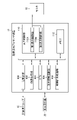
 図2は、本発明に係る医療画像処理装置として機能する超音波用プロセッサ装置の実施形態を示すブロック図である。
[Medical image processing device]
FIG. 2 is a block diagram showing an embodiment of an ultrasound processor functioning as a medical image processing apparatus according to the present invention.
 図2に示す超音波用プロセッサ装置12は、順次取得した時系列の医療画像に基づいて、医療画像内の注目領域を認識し、注目領域の認識結果を示す情報をユーザに報知するものであり、特に医療画像とともに表示する認識結果を示す情報を、注目領域を認識してからの経過時間に応じて表示形態を変更して報知する。 The ultrasound processor device 12 shown in FIG. 2 recognizes a region of interest in a medical image based on sequentially acquired time-series medical images, and notifies the user of information indicating the recognition result of the region of interest. In particular, the information indicating the recognition result displayed together with the medical image is notified by changing the display form according to the elapsed time after recognizing the attention area.
 図2に示す超音波用プロセッサ装置12は、送受信部100、画像生成部102、CPU(Central Processing Unit)104、注目領域認識部106、時間計測処理部108、表示制御部110、及びメモリ112から構成され、各部の処理は、1又は複数のプロセッサにより実現される。 The ultrasound processor device 12 shown in FIG. The processing of each unit is implemented by one or more processors.
 CPU104は、メモリ112に記憶された本発明に係る医療画像処理プログラムを含む各種のプログラムに基づいて動作し、送受信部100、画像生成部102、注目領域認識部106、時間計測処理部108、及び表示制御部110を統括制御し、また、これらの各部の一部として機能する。 The CPU 104 operates based on various programs including the medical image processing program according to the present invention stored in the memory 112. It centrally controls the display control unit 110 and functions as a part of these units.
 医療画像取得処理部として機能する送受信部100及び画像生成部102は、時系列の医療画像を順次取得する。 The transmitting/receiving unit 100 and the image generating unit 102 functioning as a medical image acquisition processing unit sequentially acquire time-series medical images.
 送受信部100の送信部は、超音波スコープ10の超音波探触子62の複数の超音波トランスデューサに印加する複数の駆動信号を生成し、図示しない走査制御部によって選択された送信遅延パターンに基づいて複数の駆動信号にそれぞれの遅延時間を与えて複数の駆動信号を複数の超音波トランスデューサに印加する。 A transmission unit of the transmission/reception unit 100 generates a plurality of drive signals to be applied to a plurality of ultrasonic transducers of the ultrasonic probe 62 of the ultrasonic scope 10, and based on a transmission delay pattern selected by a scanning control unit (not shown). to apply the plurality of drive signals to the plurality of ultrasonic transducers by giving respective delay times to the plurality of drive signals.
 送受信部100の受信部は、超音波探触子62の複数の超音波トランスデューサからそれぞれ出力される複数の検出信号を増幅し、アナログの検出信号をディジタルの検出信号(RF(Radio Frequency)データともいう)に変換する。このRFデータは、画像生成部102に入力される。 The receiving unit of the transmitting/receiving unit 100 amplifies a plurality of detection signals respectively output from the plurality of ultrasonic transducers of the ultrasonic probe 62, converts the analog detection signals into digital detection signals (also known as RF (Radio Frequency) data ). This RF data is input to the image generator 102 .
 画像生成部102は、走査制御部により選択された受信遅延パターンに基づいて、RFデータにより表される複数の検出信号にそれぞれの遅延時間を与え、それらの検出信号を加算することにより、受信フォーカス処理を行う。この受信フォーカス処理によって、超音波エコーの焦点が絞り込まれた音線データを形成する。 Based on the reception delay pattern selected by the scanning control unit, the image generation unit 102 gives respective delay times to the plurality of detection signals represented by the RF data, and adds the detection signals to obtain a reception focus. process. This reception focusing process forms sound ray data in which the focus of the ultrasonic echo is narrowed down.
 画像生成部102は、更に音線データに対して、STC(Sensitivity Timegain Control)によって、超音波の反射位置の深度に応じて距離による減衰の補正をした後、ローパスフィルタ等によって包絡線検波処理を施すことにより包絡線データを生成し、1フレーム分、より好ましくは複数フレーム分の包絡線データを、図示しないシネメモリに格納する。画像生成部102は、シネメモリに格納された包絡線データに対して、Log(対数)圧縮やゲイン調整等のプリプロセス処理を施してBモード画像を生成する。 The image generation unit 102 further corrects the attenuation due to distance according to the depth of the reflection position of the ultrasonic wave by STC (Sensitivity Timegain Control) for the sound ray data, and then performs envelope detection processing using a low-pass filter or the like. Envelope data for one frame, preferably a plurality of frames, is stored in a cine memory (not shown). The image generation unit 102 performs preprocessing such as log (logarithmic) compression and gain adjustment on the envelope data stored in the cine memory to generate a B-mode image.
 このようにして、送受信部100及び画像生成部102は、時系列のBモード画像(以下、「医療画像」という)を順次取得する。 In this way, the transmitting/receiving unit 100 and the image generating unit 102 sequentially acquire time-series B-mode images (hereinafter referred to as "medical images").
 注目領域認識部106は、医療画像に基づいて医療画像内の注目領域の位置に関する情報を認識する処理と、医療画像に基づいて注目領域を複数のクラスのうちのいずれかのクラスに分類する処理とを行うもので、例えば、AI(Artificial Intelligence)により行うことができる。 The region-of-interest recognition unit 106 performs processing for recognizing information regarding the position of the region of interest in the medical image based on the medical image, and processing for classifying the region of interest into one of a plurality of classes based on the medical image. For example, it can be done by AI (Artificial Intelligence).
 本例の注目領域は、医療画像(Bモード画像の断層像)内の各種の臓器であり、例えば、膵臓、主膵管、脾臓、脾静脈、脾動脈、胆嚢等である。 The regions of interest in this example are various organs in a medical image (B-mode image tomographic image), such as the pancreas, main pancreatic duct, spleen, splenic vein, splenic artery, and gallbladder.
 注目領域認識部106は、時系列の医療画像を順次入力すると、入力する医療画像毎に注目領域の位置を認識し、その位置に関する情報を出力するとともに、注目領域が複数のクラスのうちのいずれのクラスに属するかを認識し、その認識したクラスを示す情報(クラス情報)を出力する。 When time-series medical images are sequentially input, the attention area recognizing unit 106 recognizes the position of the attention area for each input medical image, outputs information about the position, and determines whether the attention area is one of a plurality of classes. and output information indicating the recognized class (class information).
 注目領域の位置としては、例えば、注目領域を囲む矩形の中心位置とすることができる。また、クラス情報は、本例では臓器の種類を示す情報である。 The position of the attention area can be, for example, the center position of a rectangle surrounding the attention area. Also, the class information is information indicating the type of organ in this example.
 時間計測処理部108は、注目領域認識部106により注目領域が検出されてから、その注目領域が検出されなくなるまでの経過時間を計測する部分である。時間計測処理部108は、注目領域認識部106により種類の異なる複数の注目領域が検出(認識)される場合には、注目領域毎に検出期間を示す経過時間を個別に計測する。 The time measurement processing unit 108 is a part that measures the elapsed time from when the attention area is detected by the attention area recognition unit 106 until the attention area is no longer detected. When the attention area recognition unit 106 detects (recognizes) a plurality of attention areas of different types, the time measurement processing unit 108 individually measures the elapsed time indicating the detection period for each attention area.
 表示制御部110は、時系列の医療画像を表示部であるモニタ18に表示させる第1表示制御部110Aと、注目領域に関する情報をモニタ18に表示させる第2表示制御部110Bとから構成されている。 The display control unit 110 is composed of a first display control unit 110A that displays time-series medical images on the monitor 18, which is a display unit, and a second display control unit 110B that causes the monitor 18 to display information about the attention area. there is
 第1表示制御部110Aは、送受信部100及び画像生成部102により順次取得した医療画像をモニタ18に表示させる。本例では、超音波断層像を示す動画がモニタ18に表示される。 The first display control unit 110A causes the monitor 18 to display the medical images sequentially acquired by the transmission/reception unit 100 and the image generation unit 102 . In this example, a moving image showing an ultrasonic tomographic image is displayed on the monitor 18 .
 また、第1表示制御部110Aは、超音波スコープ10の手元操作部22(ユーザ操作部)からフリーズ指示を受け付ける受付処理を行い、例えば、手元操作部22のフリーズボタンが操作され、フリーズ指示を受け付けると、モニタ18に表示する医療画像の順次表示を1枚の医療画像(現時点の医療画像)による固定表示に切り替える処理を行う。 The first display control unit 110A also performs a reception process for accepting a freeze instruction from the hand operation unit 22 (user operation unit) of the ultrasonic scope 10. For example, when the freeze button of the hand operation unit 22 is operated, the freeze instruction is issued. When the request is accepted, processing is performed to switch the sequential display of the medical images displayed on the monitor 18 to the fixed display of one medical image (current medical image).
 第2表示制御部110Bは、注目領域認識部106により認識された注目領域の分類を示すクラス情報を、モニタ18に表示された医療画像の注目領域の位置に重畳表示させるが、時間計測処理部108により測定された、その注目領域が認識されてからの経過時間に応じて、重畳表示させた注目領域に対するクラス情報の相対位置を変更させる。 The second display control unit 110B superimposes the class information indicating the classification of the attention area recognized by the attention area recognition unit 106 on the position of the attention area of the medical image displayed on the monitor 18, but the time measurement processing unit The relative position of the class information with respect to the superimposed and displayed attention area is changed according to the elapsed time from the recognition of the attention area measured by 108 .
 また、第2表示制御部110Bは、フリーズ指示を受け付けると、モニタ18に表示された医療画像が静止画として固定表示されている期間、クラス情報の注目領域に対する相対位置も固定する。 In addition, when receiving the freeze instruction, the second display control unit 110B also fixes the relative position of the class information with respect to the attention area while the medical image displayed on the monitor 18 is fixedly displayed as a still image.
 以下、第2表示制御部110Bによりモニタ18に表示される注目領域の分類を示すクラス情報等の表示例について説明する。 A display example of the class information indicating the classification of the attention area displayed on the monitor 18 by the second display control unit 110B will be described below.
 <第1表示例>
 図3は、モニタに表示される医療画像及びクラス情報の第1表示例を示す図である。
<First display example>
FIG. 3 is a diagram showing a first display example of medical images and class information displayed on a monitor.
 図3(a)は、注目領域R1,R2の検出時のモニタ18の画面を示し、図3(b)は、注目領域R1,R2が検出されてから一定時間経過後のモニタ18の画面を示している。 FIG. 3(a) shows the screen of the monitor 18 when the attention areas R1 and R2 are detected, and FIG. 3(b) shows the screen of the monitor 18 after a certain time has passed since the attention areas R1 and R2 are detected. showing.
 図3において、注目領域R1は膵臓であり、注目領域R2は脾静脈である。 In FIG. 3, the region of interest R1 is the pancreas, and the region of interest R2 is the splenic vein.
 図3(a)に示すように、注目領域R1,R2の検出時(又は検出してから一定時間未満の場合)には、注目領域R1の位置(中心位置又はその近傍位置)にクラス情報として膵臓(pancreas)の略語である“Panc.”を重畳表示させ、注目領域R2の位置に、クラス情報として脾静脈(splenic vein)の略語である“SV”を重畳表示させる。 As shown in FIG. 3A, when the attention areas R1 and R2 are detected (or when less than a certain period of time has elapsed since detection), the position of the attention area R1 (center position or its vicinity) is set as class information. "Panc.", which is an abbreviation for pancreas, is superimposed, and "SV", which is an abbreviation for splenic vein, is superimposed as class information at the position of the region of interest R2.
 このように、注目領域R1、R2が検出された場合、検出された注目領域R1、R2の分類を示すクラス情報をユーザに報知することができる。特に、注目領域R1、R2が検出したタイミングでは、注目領域R1、R2の正確な位置の同定が求められるため、各注目領域R1、R2の中心付近にクラス情報を重畳表示することが好ましい。 In this way, when the attention areas R1 and R2 are detected, the class information indicating the classification of the detected attention areas R1 and R2 can be notified to the user. In particular, when the attention areas R1 and R2 are detected, it is necessary to identify the accurate positions of the attention areas R1 and R2, so it is preferable to superimpose the class information near the center of each attention area R1 and R2.
 その後、図3(b)に示すように、注目領域R1,R2が検出されてから一定時間(例えば、数秒(1~2秒程度))経過すると、注目領域R1、R2の分類を示すクラス情報(“Panc.”、“SV”)の表示を、注目領域R1、R2の位置から離れる方向に変化(移動)させる。図3(b)の例では、クラス情報(“Panc.”、“SV”)をそれぞれ注目領域R1、R2の外側に移動させている。 Thereafter, as shown in FIG. 3(b), after a certain period of time (for example, several seconds (about 1 to 2 seconds)) has elapsed since the attention areas R1 and R2 were detected, class information indicating the classification of the attention areas R1 and R2 is displayed. The display of (“Panc.”, “SV”) is changed (moved) away from the positions of the attention areas R1 and R2. In the example of FIG. 3B, the class information (“Panc.”, “SV”) is moved outside the attention regions R1, R2, respectively.
 常に注目領域の中心付近にクラス情報を表示していては、注目領域の診断において邪魔になるという問題があるが、注目領域が検出されてから一定時間経過後は、注目領域の分類を示すクラス情報を、注目領域の外側に移動させることで、上記の問題を解決することができる。 If the class information is always displayed near the center of the attention area, there is a problem that it interferes with the diagnosis of the attention area. By moving the information outside the region of interest, the above problem can be solved.
 尚、クラス情報の移動方法は、上記のように離散的にある時間(一定時間)以降、位置を変更する方法でもよいし、時間に対して連続的に位置をずらす方法でもよい。また、図3に示す例では、クラス情報は、注目領域の臓器の種類の略語を示す文字情報であるが、注目領域の臓器の種類の正式名称を示す文字情報でもよい。 It should be noted that the method of moving the class information may be a method of discretely changing the position after a certain time (fixed time) as described above, or a method of continuously shifting the position with respect to time. In the example shown in FIG. 3, the class information is character information indicating the abbreviation of the type of organ in the attention area, but may be character information indicating the formal name of the organ type in the attention area.
 <第2表示例>
 図4は、モニタに表示される医療画像及びクラス情報の第2表示例を示す図である。
<Second display example>
FIG. 4 is a diagram showing a second display example of the medical image and class information displayed on the monitor.
 図4(a)は、注目領域R1,R3の検出時のモニタ18の画面を示し、図4(b)~図4(d)は、それぞれ注目領域R1,R3が検出されてから一定時間経過後のモニタ18の画面を示している。 FIG. 4(a) shows the screen of the monitor 18 when the attention areas R1 and R3 are detected, and FIGS. 4(b) to 4(d) show the passage of a certain time after the attention areas R1 and R3 are detected, respectively. The screen of the monitor 18 after is shown.
 図4において、注目領域R1は膵臓であり、注目領域R3は主膵管である。 In FIG. 4, the region of interest R1 is the pancreas, and the region of interest R3 is the main pancreatic duct.
 図4(a)に示すように、注目領域R1,R3の検出時には、注目領域R1の位置に、クラス情報として膵臓(pancreas)の略語である“Panc.”を重畳表示させ、注目領域R3の位置に、クラス情報として主膵管(main pancreatic duct)の略語である“MPD”を重畳表示させる。 As shown in FIG. 4A, when the attention regions R1 and R3 are detected, "Panc.", which is an abbreviation for pancreas, is displayed superimposed on the position of the attention region R1 as class information. "MPD", which is an abbreviation for main pancreatic duct, is superimposed on the position as class information.
 図4(b)に示す例では、注目領域R1,R3が検出されてから一定時間経過すると、注目領域R1、R3の分類を示すクラス情報(“Panc.”、“MPD”)を、注目領域R1、R3の外側に移動させる。 In the example shown in FIG. 4B, after a certain period of time has elapsed since the attention areas R1 and R3 were detected, the class information (“Panc.”, “MPD”) indicating the classification of the attention areas R1 and R3 is transferred to the attention area. Move outside R1 and R3.
 この場合、クラス情報(“Panc.”、“MPD”)の位置を経過時間に応じて変化させる際に、分類したクラスに応じて変化の態様を変更させることが好ましい。即ち、図4(b)に示す例では、注目領域R1の分類を示すクラス情報(“Panc.”)は、図4(b)上で注目領域R1の左上に移動させ、注目領域R3のクラス情報(“MPD”)は、図4(b)上で注目領域R3の右下に移動させる。複数のクラス情報をそれぞれ移動させた場合、これらのクラス情報が近接しないようにするためである。 In this case, when changing the position of the class information ("Panc.", "MPD") according to the elapsed time, it is preferable to change the mode of change according to the classified class. That is, in the example shown in FIG. 4B, the class information (“Panc.”) indicating the classification of the attention area R1 is moved to the upper left of the attention area R1 in FIG. The information (“MPD”) is moved to the lower right of the attention area R3 on FIG. 4(b). This is to prevent the pieces of class information from being close to each other when each piece of class information is moved.
 また、図4(c)及び(d)に示す例では、注目領域R1,R3が検出されてから一定時間経過すると、注目領域R3のクラス情報(“MPD”)を注目領域R3の外側に移動させ、一方、注目領域R1の分類を示すクラス情報(“Panc.”)の注目領域R3に対する相対位置は固定する。即ち、複数のクラスのうちの1つ以上の特定クラスの分類を示すクラス情報(本例では、(“Panc.”))については、特定クラスの分類を示すクラス情報の注目領域に対する相対位置は移動させずに固定表示とする。 Further, in the examples shown in FIGS. 4(c) and 4(d), after a certain period of time has elapsed since the attention areas R1 and R3 were detected, the class information (“MPD”) of the attention area R3 is moved outside the attention area R3. On the other hand, the relative position of the class information (“Panc.”) indicating the classification of the attention area R1 with respect to the attention area R3 is fixed. That is, for class information indicating one or more specific class classifications among a plurality of classes ((“Panc.”) in this example), the relative position of the class information indicating the specific class classification with respect to the attention area is Fixed display without moving.
 図4(a)に示すように、注目領域R1と注目領域R3とは大きさが異なり、注目領域R1は比較的に大きいが、注目領域R3は小さい。注目領域R3が小さい場合、小さい注目領域R3の位置に注目領域の分類を示すクラス情報(“MPD”)を重畳表示すると、注目領域R3の視認性が大きく低下する。一方、注目領域R1が大きい場合、大きい注目領域R1の位置に注目領域の分類を示すクラス情報(“Panc.”)を重畳表示させても、注目領域R3の視認性の低下は少ない。 As shown in FIG. 4(a), the attention area R1 and the attention area R3 are different in size, and the attention area R1 is relatively large, while the attention area R3 is small. When the attention area R3 is small, superimposing the class information (“MPD”) indicating the classification of the attention area on the position of the small attention area R3 greatly reduces the visibility of the attention area R3. On the other hand, when the attention area R1 is large, even if the class information (“Panc.”) indicating the classification of the attention area is superimposed on the position of the large attention area R1, the visibility of the attention area R3 is hardly lowered.
 このように、注目領域にその注目領域の分類を示すクラス情報を重畳表示させても、注目領域の視認性が大幅に低下しない特定のクラス情報については、注目領域が検出されてから一定時間経過後も移動させないようにしてもよい。 As described above, even if the class information indicating the classification of the attention area is superimposed on the attention area, the visibility of the attention area does not significantly decrease, and the specific class information does not significantly deteriorate the attention area. It may be arranged not to be moved afterward.
 尚、図4(d)に示す表示例は、クラス情報(“MPD”)の移動後、注目領域R3とクラス情報(“MPD”)とを引き出し線で接続し、両者の関係性を明確にしている点で、図4(c)に示す表示例と相違する。 In the display example shown in FIG. 4(d), after the class information (“MPD”) is moved, the attention area R3 and the class information (“MPD”) are connected with a leader line to clarify the relationship between the two. The display example differs from the display example shown in FIG.
 <第3表示例>
 図5は、モニタに表示される医療画像及びクラス情報の第3表示例を示す図である。
<Third display example>
FIG. 5 is a diagram showing a third display example of the medical image and class information displayed on the monitor.
 図5(a)は、注目領域R1,R2の検出時のモニタ18の画面を示し、図5(b)は、注目領域R1,R2が検出されてから一定時間経過後のモニタ18の画面を示している。 FIG. 5(a) shows the screen of the monitor 18 when the attention areas R1 and R2 are detected, and FIG. 5(b) shows the screen of the monitor 18 after a certain period of time has elapsed since the attention areas R1 and R2 were detected. showing.
 図5に示す第3表示例は、図3に示した第1表示例と比較して、注目領域R1,R2の検出時のクラス情報の表示形態が相違する。 The third display example shown in FIG. 5 differs from the first display example shown in FIG. 3 in the display form of the class information when the attention areas R1 and R2 are detected.
 図5(a)に示すように注目領域R1,R2の検出時には、注目領域R1の位置にクラス情報として膵臓を示すマーカ(丸印)を重畳表示させ、注目領域R2の位置に、クラス情報として脾静脈を示すマーカ(星印)を重畳表示させる。尚、注目領域の分類を示すクラス情報の種類とマーカの種類とは、予め対応づけておくことで、ユーザは、注目領域の位置に重畳表示されたマーカの種類を視認することで、クラス情報を確認することができる。 As shown in FIG. 5A, when the attention areas R1 and R2 are detected, a marker (circle) indicating the pancreas is superimposed on the position of the attention area R1 as class information, and a marker (circle) indicating the pancreas is superimposed on the attention area R2 as class information. A marker (asterisk) indicating the splenic vein is displayed superimposed. Note that the type of class information indicating the classification of the attention area and the type of the marker are associated in advance, so that the user can visually recognize the type of the marker superimposed on the position of the attention area to obtain the class information. can be confirmed.
 また、図5(b)に示すように注目領域R1,R2が検出されてから一定時間経過後は、クラス情報を示すマーカを消去し、図3(b)と同様に注目領域R1,R2の外側に注目領域R1、R2の分類を示すクラス情報(“Panc.”、“SV”)を表示させる。 Further, as shown in FIG. 5(b), after a certain period of time has elapsed since the attention areas R1 and R2 were detected, the markers indicating the class information are erased, and the attention areas R1 and R2 are displayed in the same manner as in FIG. 3(b). Class information (“Panc.”, “SV”) indicating the classification of the attention regions R1 and R2 is displayed outside.
 即ち、図5に示す第3表示例では、一定時間経過後は、クラス情報を移動させるとともに、クラス情報の表示形態もマーカから文字情報に表示形態も変化させている。 That is, in the third display example shown in FIG. 5, after a certain period of time has passed, the class information is moved, and the display form of the class information is changed from the marker to the character information.
 図5の第3表示例によれば、マーカは、文字情報と比較して小さく表示することが可能であり、注目領域の正確な位置情報を視認性良く表示することができる。また、一定時間経過後にクラス情報をマーカから文字情報に変化させることで、クラス情報の詳細な情報が解釈容易な態様で示すことができる。 According to the third display example of FIG. 5, the marker can be displayed smaller than the character information, and accurate position information of the attention area can be displayed with good visibility. Further, by changing the class information from markers to character information after a certain period of time has elapsed, detailed information of the class information can be displayed in an easily interpretable manner.
 <第4表示例>
 図6は、モニタに表示される医療画像及びクラス情報の第4表示例を示す図である。
<Fourth display example>
FIG. 6 is a diagram showing a fourth display example of the medical image and class information displayed on the monitor.
 図6(a)は、注目領域R1,R2の検出時のモニタ18の画面を示し、図6(b)は、注目領域R1,R2が検出されてから一定時間経過後のモニタ18の画面を示している。 FIG. 6(a) shows the screen of the monitor 18 when the attention areas R1 and R2 are detected, and FIG. 6(b) shows the screen of the monitor 18 after a certain period of time has elapsed since the attention areas R1 and R2 were detected. showing.
 図6に示す第4表示例は、図3に示した第1表示例と比較して、注目領域R1,R2をそれぞれ強調する強調情報を更に表示する点で相違する。 The fourth display example shown in FIG. 6 is different from the first display example shown in FIG. 3 in that emphasis information for emphasizing the attention regions R1 and R2 is further displayed.
 図6に示す注目領域R1,R2をそれぞれ強調する強調情報は、注目領域R1,R2が検出されてからの時間経過にかかわらず、注目領域R1,R2に対する相対位置を固定して表示する。即ち、動画である医療画像内で注目領域R1,R2が移動する場合には、注目領域R1,R2に伴って強調情報も移動するが、注目領域R1,R2に対する強調情報の相対位置は固定される。 The emphasis information that emphasizes the attention areas R1 and R2 shown in FIG. 6 is displayed with the relative positions with respect to the attention areas R1 and R2 fixed regardless of the time elapsed since the attention areas R1 and R2 were detected. That is, when the attention regions R1 and R2 move in the moving image medical image, the emphasis information also moves along with the attention regions R1 and R2, but the relative positions of the emphasis information with respect to the attention regions R1 and R2 are fixed. be.
 図6に示す注目領域R1,R2をそれぞれ強調する強調情報は、注目領域を囲む矩形枠(バウンディングボックス)である。注目領域を囲むバウンディングボックスは、注目領域認識部106から取得することができる。また、バウンディングボックスの対角線の交点を、注目領域の中心位置とすることができる。 The emphasis information that emphasizes the attention areas R1 and R2 shown in FIG. 6 is a rectangular frame (bounding box) that surrounds the attention areas. A bounding box surrounding the attention area can be obtained from the attention area recognition unit 106 . Also, the intersection of the diagonal lines of the bounding box can be set as the center position of the attention area.
 バウンディングボックスは、注目領域の分類を示すクラス情報にかかわらず、同一の色(例えば、白)及び同一の線種にしてよいし、注目領域の分類を示すクラス情報に対応して色及び/又は線種が異なるものでもよい。後者の場合、バウンディングボックスは、クラス情報を含むことになる。 The bounding box may have the same color (for example, white) and the same line type regardless of the class information indicating the classification of the attention area, or the color and/or Different line types may be used. In the latter case the bounding box will contain the class information.
 バウンディングボックスは、注目領域R1,R2が内接するように、又は注目領域R1,R2よりも僅かに大きく表示させることができ、これにより注目領域の視認性を低下させないため、注目領域R1,R2が検出されてからの時間経過にかかわらず、固定表示しても支障がない。 The bounding box can be displayed so that the regions of interest R1 and R2 are inscribed or slightly larger than the regions of interest R1 and R2. Regardless of how long it has been since detection, there is no problem with fixed display.
 尚、各注目領域を強調する強調情報は、バウンディングボックスに限らず、例えば、注目領域を囲む円や楕円、注目領域の中心に配置するマーカや図形(注目領域のクラスに依存せず、同じ形状のもの)、あるいは注目領域の位置を示す矢印などが考えられる。 Note that the emphasis information for emphasizing each attention area is not limited to the bounding box. ), or an arrow indicating the position of the attention area.
 図3から図6に示した第1表示例から第4表示例は、クラス情報を文字情報(略語を含む)、マーカ等により識別可能に表示するが、クラス情報を図形により識別可能に表示するようにしてもよい。例えば、クラス情報に応じて色分けしたバウンディングボックスは、図形に含まれる。また、マーカと図形の表示形態は明確に区別できない場合があり、例えば、図5(a)に示したマーカ(丸印、星印)は、図形とも言える。 In the first to fourth display examples shown in FIGS. 3 to 6, the class information is displayed identifiably by character information (including abbreviations), markers, etc., but the class information is displayed identifiably by graphics. You may do so. For example, bounding boxes that are colored according to class information are included in the graphics. Further, there are cases where the display form of the marker and the figure cannot be clearly distinguished. For example, the markers (circles and stars) shown in FIG. 5A can be said to be figures.
 また、クラス情報の表示方法、及び検出時からの経過時間に伴うクラス情報の位置等の遷移方法は、第1表示例から第4表示例に限らず、種々の方法が考えられる。 In addition, the method of displaying class information and the method of transitioning the position of class information according to the elapsed time from the time of detection are not limited to the first to fourth display examples, and various methods are conceivable.
 [医療画像処理方法]
 <第1実施形態>
 図7は、本発明に係る医療画像処理方法の第1実施形態を示すフローチャートであり、図2に示した超音波用プロセッサ装置12の各部の処理手順に関して示している。
[Medical image processing method]
<First embodiment>
FIG. 7 is a flow chart showing the first embodiment of the medical image processing method according to the present invention, showing the processing procedure of each part of the ultrasonic processor device 12 shown in FIG.
 図7において、CPU104は、まず、複数の注目領域(本例では、複数の臓器)がそれぞれ認識されてからの経過時間を示すタイマーTiのカウント値を、それぞれゼロ(Ti=0)にリセットする(ステップS10)。ここで、iは、臓器の種類の数(クラス数)をn個とした場合、1~nの臓器の種類を示すパラメータである。したがって、T1は、1番目の種類の臓器に対応するタイマーであり、Tnは、n番目の種類の臓器に対応するタイマーである。 In FIG. 7, the CPU 104 first resets the count value of the timer Ti indicating the elapsed time since each of the plurality of attention areas (in this example, the plurality of organs) was recognized to zero (Ti=0). (Step S10). Here, i is a parameter indicating the type of organ from 1 to n, where n is the number of types of organ (the number of classes). Thus, T1 is the timer corresponding to the first type of organ and Tn is the timer corresponding to the nth type of organ.
 医療画像取得処理部として機能する送受信部100及び画像生成部102は、時系列の医療画像を順次取得する(ステップS12)。時系列の医療画像のフレームレートが、例えば、30fps(frames per second)の場合、1/30(秒)毎に1フレーム分の医療画像を取得する。 The transmitting/receiving unit 100 and the image generating unit 102 functioning as a medical image acquisition processing unit sequentially acquire time-series medical images (step S12). When the frame rate of time-series medical images is, for example, 30 fps (frames per second), one frame of medical images is acquired every 1/30 (second).
 続いて、注目領域認識部106は、ステップS12で取得した医療画像に基づいて医療画像内に存在する注目領域(臓器)Ri(i=1~n)の認識処理を行う(ステップS14)。即ち、注目領域認識部106は、医療画像内に存在する注目領域Riの位置の認識と、その注目領域Riの分類を示すクラス(臓器の種類)の認識を行う。医療画像内に注目領域が複数存在する場合には、各注目領域の位置の認識と各注目領域のクラスの認識を行う。 Subsequently, the attention area recognition unit 106 performs recognition processing of attention areas (organs) Ri (i=1 to n) existing in the medical image based on the medical image acquired in step S12 (step S14). That is, the attention area recognizing unit 106 recognizes the position of the attention area Ri existing in the medical image, and recognizes the class (type of organ) indicating the classification of the attention area Ri. When there are a plurality of attention areas in the medical image, recognition of the position of each attention area and recognition of the class of each attention area are performed.
 注目領域認識部106による注目領域Riの認識と並行して、第1表示制御部110Aは、ステップS12で取得した医療画像をモニタ18に表示させる(ステップS20(第1表示制御ステップS16))。 In parallel with the recognition of the attention area Ri by the attention area recognition unit 106, the first display control unit 110A causes the monitor 18 to display the medical image acquired in step S12 (step S20 (first display control step S16)).
 CPU104は、ステップS14により注目領域Riが認識されたか否かを判別し、注目領域Riが認識された場合、ステップS20(第2表示制御ステップS20)に遷移させる(ステップS18)。 The CPU 104 determines whether or not the attention area Ri is recognized in step S14, and if the attention area Ri is recognized, the process proceeds to step S20 (second display control step S20) (step S18).
 ステップS20において、第2表示制御部110Bは、注目領域Riの分類を示すクラス情報Ci(i=1~n)をモニタ18に表示された医療画像の注目領域Riの位置に重畳表示させる。例えば、図3に示した第1表示例の場合、膵臓を示す注目領域R1と、脾静脈を示す注目領域R2が認識されており、注目領域R1の中心付近の位置に注目領域R1の分類を示すクラス情報C1(“Panc.”)を重畳表示させ、注目領域R2の中心付近の位置に注目領域R2の分類を示すクラス情報C2(“SV”)を重畳表示させている。 In step S20, the second display control unit 110B superimposes the class information Ci (i=1 to n) indicating the classification of the attention area Ri on the position of the attention area Ri of the medical image displayed on the monitor . For example, in the case of the first display example shown in FIG. 3, a region of interest R1 indicating the pancreas and a region of interest R2 indicating the splenic vein are recognized, and the region of interest R1 is classified at a position near the center of the region of interest R1. class information C1 (“Panc.”) indicating the target region R2 is superimposed and displayed, and class information C2 (“SV”) indicating the classification of the target region R2 is superimposed and displayed at a position near the center of the target region R2.
 続いて、時間計測処理部108は、タイマーTi(i=1~n)のカウント値を1だけインクリメントする(ステップS22)。本例のタイマーTiのカウント値は、注目領域Riが最初に検出されてから時系列の医療画像から同じ注目領域Riが連続して検出されている場合のフレーム数に対応している。したがって、フレームレートが30fpsの場合に、注目領域R1が連続して検出されている場合のタイマーT1のカウント値が30の場合、1秒を意味する。即ち、タイマーTiのカウント値は、注目領域Riが認識されてからの経過時間を示す。 Subsequently, the time measurement processing unit 108 increments the count value of the timer Ti (i=1 to n) by 1 (step S22). The count value of the timer Ti in this example corresponds to the number of frames when the same attention area Ri is continuously detected from time-series medical images after the attention area Ri is first detected. Therefore, when the frame rate is 30 fps and the count value of the timer T1 is 30 when the attention area R1 is continuously detected, it means 1 second. That is, the count value of the timer Ti indicates the elapsed time since the attention area Ri was recognized.
 次に、CPU104は、タイマーTiのカウント値が閾値Th以上か否かを判別する(ステップS24)。閾値Thは、例えば、45にすることができる。閾値Th(=45)を、フレームレートが30fpsの場合の時間に換算すると、1.5秒である。 Next, the CPU 104 determines whether or not the count value of the timer Ti is greater than or equal to the threshold Th (step S24). The threshold Th can be set to 45, for example. When the threshold Th (=45) is converted into time when the frame rate is 30 fps, it is 1.5 seconds.
 CPU104は、タイマーTiのカウント値が閾値Th未満の場合、ステップS12に遷移させる。これにより、ステップS12からステップS24の処理が繰り返し行われる。 When the count value of the timer Ti is less than the threshold Th, the CPU 104 makes a transition to step S12. As a result, the processing from step S12 to step S24 is repeated.
 一方、CPU104は、タイマーTiのカウント値が閾値Th以上の場合、ステップS26に遷移させる。 On the other hand, when the count value of the timer Ti is equal to or greater than the threshold Th, the CPU 104 makes a transition to step S26.
 ステップS26において、第2表示制御部110Bは、ステップS20により重畳表示させた注目領域Riに対するクラス情報Ciの相対位置を、注目領域Riの中心付近の位置から離れる方向に移動させる。 In step S26, the second display control unit 110B moves the relative position of the class information Ci with respect to the attention area Ri superimposed and displayed in step S20 in a direction away from the position near the center of the attention area Ri.
 例えば、図3に示した第1表示例の場合、図3(a)に示すように注目領域R1、R2の中心付近の位置に重畳表示させた注目領域R1、R2の分類を示すクラス情報(“Panc.”、“SV”)の表示を、図3(b)に示すように注目領域R1、R2の外側に移動させる。 For example, in the case of the first display example shown in FIG. 3, class information ( "Panc.", "SV") are moved outside the attention areas R1 and R2 as shown in FIG. 3(b).
 このように注目領域Riが検出されてから一定時間(本例では、1.5秒)経過後は、注目領域Riの分類を示すクラス情報Ciを、注目領域Riの外側に移動させることで、注目領域Riの診断に、クラス情報Ciの表示が邪魔にならないようにしている。 After a certain period of time (1.5 seconds in this example) has passed since the attention area Ri was detected in this way, the class information Ci indicating the classification of the attention area Ri is moved outside the attention area Ri, The display of the class information Ci does not interfere with the diagnosis of the attention area Ri.
 一方、ステップS18において、注目領域Riが認識されていないと判別されると(「No」の場合)、CPU104は、前回(1フレーム前)の医療画像において、注目領域Riが認識されていたか否かを更に判別する(ステップS28)。 On the other hand, if it is determined in step S18 that the attention area Ri has not been recognized ("No"), the CPU 104 determines whether the attention area Ri was recognized in the previous (one frame previous) medical image. It is further determined whether or not (step S28).
 CPU104は、前回の医療画像においても、注目領域Riが認識されていないと判別すると、ステップS12に遷移させ、前回の医療画像において、注目領域Riが認識されていたと判別すると、ステップS30に遷移させる。 If the CPU 104 determines that the region of interest Ri has not been recognized in the previous medical image as well, the process proceeds to step S12, and if it determines that the region of interest Ri has been recognized in the previous medical image, the process proceeds to step S30. .
 ステップS30において、前回の医療画像では注目領域Riが認識されていたが、今回の医療画像では注目領域Riが認識されないため、第2表示制御部110Bは、モニタ18に表示させたクラス情報Ciの表示を終了させる。 In step S30, the region of interest Ri was recognized in the previous medical image, but the region of interest Ri is not recognized in the current medical image. End the display.
 クラス情報Ciの表示終了と同時にCPU104は、タイマーTiのカウント値をゼロにリセットさせ(ステップS32)、ステップS12に遷移させる。 At the same time when the display of the class information Ci ends, the CPU 104 resets the count value of the timer Ti to zero (step S32), and transitions to step S12.
 尚、ステップS20において、注目領域Riの位置にクラス情報Ciを重畳表示する場合のクラス情報Ciは、注目領域Riである臓器の種類の名称又は略称を示す文字情報に限らず、臓器の種類を示すマーカ、図形等の他の表示形態でもよい。 In step S20, the class information Ci when the class information Ci is displayed superimposed on the position of the attention area Ri is not limited to character information indicating the name or abbreviation of the type of organ in the attention area Ri. Other display forms, such as markers and graphics, may be used.
 また、ステップS26において、注目領域Riが認識されてから一定時間経過後(タイマーTiのカウント値が閾値Th以上の場合)、注目領域Riの中心付近の位置に表示させたクラス情報Ciは、注目領域Riの外側に移動させるが、注目領域Riの分類を示すクラス情報Ciに応じて移動させる方向を変更することができる(図4(b)参照)。 Further, in step S26, after a certain period of time has elapsed since the attention area Ri was recognized (when the count value of the timer Ti is equal to or greater than the threshold value Th), the class information Ci displayed at a position near the center of the attention area Ri becomes the attention area Ri. Although it is moved outside the region Ri, the direction of movement can be changed according to the class information Ci indicating the classification of the attention region Ri (see FIG. 4B).
 また、図4(c)及び(d)に示すように特定クラスのクラス情報(膵臓を示す“Panc.”)は、一定時間経過後も注目領域の位置から移動させないようにしてもよい。また、図4(d)に示すように移動させたクラス情報(“MPD”)と注目領域R3とをき出し線で接続し、両者の関係性を明確にすることができる。 Also, as shown in FIGS. 4(c) and (d), the class information of the specific class ("Panc." indicating pancreas) may not be moved from the position of the attention area even after a certain period of time has elapsed. Also, as shown in FIG. 4(d), the moved class information (“MPD”) and the attention area R3 are connected by a line to clarify the relationship between the two.
 更に図5に示したように一定時間経過前のクラス情報Ciを示すマーカによる表示形態から、一定時間経過後のクラス情報Ciを示す文字情報による表示形態に変更してもよい。 Furthermore, as shown in FIG. 5, the display form of the marker indicating the class information Ci before the lapse of a certain period of time may be changed to the display form of the character information indicating the class information Ci after the lapse of the certain period of time.
 <第2実施形態>
 図8は、本発明に係る医療画像処理方法の第2実施形態を示すフローチャートである。
<Second embodiment>
FIG. 8 is a flow chart showing a second embodiment of the medical image processing method according to the present invention.
 尚、図8において、図7に示した第1実施形態のフローチャートと共通するステップには、同一のステップ番号を付し、その詳細な説明は省略する。 It should be noted that in FIG. 8, the same step numbers are assigned to steps that are common to the flowchart of the first embodiment shown in FIG. 7, and detailed description thereof will be omitted.
 図8に示す第2実施形態の医療画像処理方法は、ステップS40の処理が追加されている点で、図7に示した第1実施形態の医療画像処理方法と相違する。 The medical image processing method of the second embodiment shown in FIG. 8 differs from the medical image processing method of the first embodiment shown in FIG. 7 in that the process of step S40 is added.
 図8に示すステップS40(第2表示制御ステップS40)は、注目領域Riが認識されてから一定時間経過後(タイマーTiのカウント値が閾値Th以上の場合)、更に注目領域Riの分類を示すクラス情報Ciが、特定クラスのクラス情報か否かを判別する。 Step S40 (second display control step S40) shown in FIG. 8 further indicates the classification of the attention area Ri after a certain period of time has elapsed since the attention area Ri was recognized (when the count value of the timer Ti is equal to or greater than the threshold value Th). It is determined whether or not the class information Ci is class information of a specific class.
 ステップS40において、注目領域Riの分類を示すクラス情報Ciが、特定クラスのクラス情報であると判別されると(「Yes」の場合)、ステップS12に遷移させる。この場合、ステップS26に遷移しないため、特定クラスを示すクラス情報の位置は、特定クラスの注目領域が検出されてからの経過時間にかかわらず、固定される。 If it is determined in step S40 that the class information Ci indicating the classification of the attention area Ri is class information of a specific class ("Yes"), the process proceeds to step S12. In this case, since the process does not proceed to step S26, the position of the class information indicating the specific class is fixed regardless of the elapsed time since the attention area of the specific class was detected.
 例えば、図4(c)及び(d)に示す表示例では、特定クラスを示すクラス情報(膵臓を示す“Panc.”)は、一定時間経過後も注目領域の位置から移動させないようにしている。 For example, in the display examples shown in FIGS. 4(c) and 4(d), class information indicating a specific class ("Panc." indicating pancreas) is kept from moving from the position of the attention area even after a certain period of time has elapsed. .
 膵臓のように比較的大きな注目領域の場合、注目領域にクラス情報を重畳表示しても注目領域の観察の邪魔にならず、又は観察の邪魔になる程度が低いためである。 This is because, in the case of a relatively large region of interest such as the pancreas, even if the class information is superimposed on the region of interest, it does not interfere with observation of the region of interest, or the degree of interference with observation is low.
 <第3実施形態>
 図9は、本発明に係る医療画像処理方法の第3実施形態を示すフローチャートである。
<Third Embodiment>
FIG. 9 is a flow chart showing a third embodiment of a medical image processing method according to the present invention.
 尚、図9において、図7に示した第1実施形態のフローチャートと共通するステップには、同一のステップ番号を付し、その詳細な説明は省略する。 In FIG. 9, steps common to those in the flowchart of the first embodiment shown in FIG. 7 are given the same step numbers, and detailed description thereof will be omitted.
 図9に示す第3実施形態の医療画像処理方法は、ステップS50、S40の処理が追加されている点で、図7に示した第1実施形態の医療画像処理方法と相違する。 The medical image processing method of the third embodiment shown in FIG. 9 differs from the medical image processing method of the first embodiment shown in FIG. 7 in that the processes of steps S50 and S40 are added.
 図9に示すステップS50は、超音波スコープ10の手元操作部22からフリーズ指示を受け付けたか否かを判別する。 In step S50 shown in FIG. 9, it is determined whether or not a freeze instruction has been received from the handheld operation unit 22 of the ultrasonic scope 10.
 フリーズ指示を受け付けたと判別されると(「Yes」の場合)、ステップS52に遷移させ、ここで、フリーズ解除指示を受け付けたか否かが判別される。ステップS52において、フリーズ解除指示を受け付けていないと判別されると(「No」の場合)、ステップS50に戻り、フリーズ解除指示を受け付けたと判別されると(「Yes」の場合)、ステップS22に遷移させる。 When it is determined that the freeze instruction has been received (if "Yes"), the process proceeds to step S52, where it is determined whether or not the freeze release instruction has been received. If it is determined in step S52 that the freeze release instruction has not been received ("No"), the process returns to step S50, and if it is determined that the freeze release instruction has been received ("Yes"), the process proceeds to step S22. transition.
 即ち、フリーズ指示を受け付けると、フリーズ解除指示を受け付けるまで、ステップS12に遷移することがなく、その結果、ステップS12における新たな医療画像の取得、及びステップS16における新たな医療画像の順次表示が停止し、モニタ18にはフリーズ指示を受け付けた時点の医療画像が表示(静止画として固定表示)される。 That is, when the freeze instruction is received, the transition to step S12 does not occur until the freeze release instruction is received, and as a result, acquisition of new medical images in step S12 and sequential display of new medical images in step S16 are stopped. Then, the monitor 18 displays (fixedly displays as a still image) the medical image at the time when the freeze instruction is received.
 また、フリーズ指示を受け付けると、フリーズ解除指示を受け付けるまでの期間、フリーズ指示を受け付けた時点の医療画像から認識された注目領域Riの分類を示すクラス情報Ciも固定表示される。 In addition, when the freeze instruction is accepted, the class information Ci indicating the classification of the attention area Ri recognized from the medical image at the time the freeze instruction is accepted is also fixedly displayed during the period until the freeze release instruction is accepted.
 このようにフリーズ指示を受け付けると、フリーズ指示が解除されるまでの期間、モニタ18に表示される医療画像は、フリーズ指示を受け付けた時点の医療画像に固定され、動画表示から静止画表示に切り替わる。また、フリーズ指示を受け付けた時点の医療画像から注目領域Riが認識されている場合には、その注目領域Riの分類を示すクラス情報Ciの表示も固定される。 When the freeze instruction is accepted in this way, the medical image displayed on the monitor 18 is fixed to the medical image at the time the freeze instruction is accepted, and the moving image display is switched to the still image display until the freeze instruction is canceled. . Further, when the attention area Ri is recognized from the medical image at the time when the freezing instruction is received, the display of the class information Ci indicating the classification of the attention area Ri is also fixed.
 [その他]
 本実施形態では、超音波用プロセッサ装置12が、本発明に係る医療画像処理装置としての機能を備えているが、これに限らず、超音波用プロセッサ装置12とは別体のパーソナルコンピュータ等が、超音波用プロセッサ装置12から時系列の医療画像を取得し、本発明に係る医療画像処理装置として機能するものでもよい。
[others]
In the present embodiment, the ultrasound processor device 12 has the function as the medical image processing device according to the present invention, but the present invention is not limited to this, and a personal computer or the like separate from the ultrasound processor device 12 may be used. , acquires time-series medical images from the ultrasound processor 12 and functions as a medical image processing apparatus according to the present invention.
 また、時系列の医療画像は、超音波画像に限らず、例えば、超音波スコープ10の先端部本体50に設けられた対物レンズ及び撮像素子等により撮影され、内視鏡用プロセッサ装置14から出力される時系列の内視鏡画像でもよい。 In addition, the time-series medical images are not limited to ultrasonic images. For example, they are captured by an objective lens and an imaging element provided in the distal end main body 50 of the ultrasonic scope 10, and output from the endoscope processor device 14. It may be time-series endoscopic images.
 更に、医療画像内の注目領域は、各種の臓器に限らず、例えば、病変領域でもよい。この場合、病変領域のクラスとしては、腫瘍、非腫瘍、その他等が考えられる。 Furthermore, the region of interest in the medical image is not limited to various organs, and may be, for example, a lesion region. In this case, classes of lesion areas may include tumor, non-tumor, and others.
 また、上記実施形態の超音波用プロセッサ装置(医療画像処理装置)の各種制御を実行するハードウェア的な構造は、次に示すような各種のプロセッサ(processor)である。各種のプロセッサには、ソフトウェア(プログラム)を実行して各種の制御部として機能する汎用的なプロセッサであるCPU(Central Processing Unit)、FPGA(Field Programmable Gate Array)などの製造後に回路構成を変更可能なプロセッサであるプログラマブルロジックデバイス(Programmable Logic Device:PLD)、ASIC(Application Specific Integrated Circuit)などの特定の処理を実行させるために専用に設計された回路構成を有するプロセッサである専用電気回路などが含まれる。 Also, the hardware structure for executing various controls of the ultrasound processor device (medical image processing device) of the above embodiment is the following various processors. For various processors, the circuit configuration can be changed after manufacturing, such as CPU (Central Processing Unit), FPGA (Field Programmable Gate Array), which is a general-purpose processor that executes software (program) and functions as various control units. Programmable Logic Device (PLD), which is a processor, ASIC (Application Specific Integrated Circuit), etc. be
 1つの処理部は、これら各種のプロセッサのうちの1つで構成されていてもよいし、同種又は異種の2つ以上のプロセッサ(例えば、複数のFPGA、あるいはCPUとFPGAの組み合わせ)で構成されてもよい。また、複数の制御部を1つのプロセッサで構成してもよい。複数の制御部を1つのプロセッサで構成する例としては、第1に、クライアントやサーバなどのコンピュータに代表されるように、1つ以上のCPUとソフトウェアの組合せで1つのプロセッサを構成し、このプロセッサが複数の制御部として機能する形態がある。第2に、システムオンチップ(System On Chip:SoC)などに代表されるように、複数の制御部を含むシステム全体の機能を1つのIC(Integrated Circuit)チップで実現するプロセッサを使用する形態がある。このように、各種の制御部は、ハードウェア的な構造として、上記各種のプロセッサを1つ以上用いて構成される。 One processing unit may be composed of one of these various processors, or composed of two or more processors of the same type or different types (for example, a plurality of FPGAs, or a combination of a CPU and an FPGA). may Also, a plurality of control units may be configured by one processor. As an example of configuring a plurality of control units with one processor, first, one processor is configured with a combination of one or more CPUs and software, as typified by a computer such as a client or a server. There is a form in which a processor functions as multiple controllers. Second, as typified by System On Chip (SoC), etc., there is a form of using a processor that realizes the functions of the entire system including multiple control units with a single IC (Integrated Circuit) chip. be. In this way, various control units are configured using one or more of the above various processors as a hardware structure.
 更に、本発明は、コンピュータにインストールされることにより、コンピュータを本発明に係る医療画像処理装置として機能させる医療画像処理プログラム、及びこの医療画像処理プログラムが記録された不揮発性の記憶媒体を含む。 Furthermore, the present invention includes a medical image processing program that, when installed in a computer, causes the computer to function as the medical image processing apparatus according to the present invention, and a non-volatile storage medium in which this medical image processing program is recorded.
 更にまた、本発明は上述した実施形態に限定されず、本発明の精神を逸脱しない範囲で種々の変形が可能であることは言うまでもない。 Furthermore, it goes without saying that the present invention is not limited to the above-described embodiments, and that various modifications are possible without departing from the spirit of the present invention.
2 超音波内視鏡システム
10 超音波スコープ
12 超音波用プロセッサ装置
14 内視鏡用プロセッサ装置
16 光源装置
18 モニタ
20 挿入部
20a 長手軸
22 手元操作部
24 ユニバーサルコード
26 超音波用コネクタ
28 内視鏡用コネクタ
30 光源用コネクタ
32、34 チューブ
36 送気送水ボタン
38 吸引ボタン
42 アングルノブ
44 処置具挿入口
50 先端部本体
52 湾曲部
54 軟性部
62 超音波探触子
64 バルーン
70 送水タンク
72 吸引ポンプ
100 送受信部
102 画像生成部
104 CPU
106 注目領域認識部
108 時間計測処理部
110 表示制御部
110A 第1表示制御部
110B 第2表示制御部
112 メモリ
C1、C2、Ci クラス情報
R1、R2、R3、Ri 注目領域
S10~S32、S40、S50、S52 ステップ
2 Ultrasound Endoscope System 10 Ultrasound Scope 12 Ultrasound Processor Device 14 Endoscope Processor Device 16 Light Source Device 18 Monitor 20 Insertion Portion 20a Longitudinal Axis 22 Hand Operation Part 24 Universal Cord 26 Ultrasound Connector 28 Endoscopy Speculum connector 30 Light source connectors 32, 34 Tube 36 Air supply/water supply button 38 Suction button 42 Angle knob 44 Treatment instrument insertion port 50 Distal portion main body 52 Bending portion 54 Flexible portion 62 Ultrasonic probe 64 Balloon 70 Water supply tank 72 Suction Pump 100 Transmission/reception unit 102 Image generation unit 104 CPU
106 attention area recognition unit 108 time measurement processing unit 110 display control unit 110A first display control unit 110B second display control unit 112 memories C1, C2, Ci class information R1, R2, R3, Ri attention areas S10 to S32, S40, S50, S52 step

Claims (20)

  1.  プロセッサを備えた医療画像処理装置において、
     前記プロセッサは、
     時系列の医療画像を順次取得する医療画像取得処理と、
     前記医療画像を表示部に順次表示させる第1表示制御と、
     前記順次取得した前記医療画像に基づいて前記医療画像内の注目領域の位置に関する情報を認識する処理と、
     前記順次取得した前記医療画像に基づいて前記注目領域を複数のクラスのうちのいずれかのクラスに分類する処理と、
     前記分類した前記クラスを示すクラス情報を、前記表示部に表示された前記医療画像の前記注目領域の位置に重畳表示させる第2表示制御と、を行い、
     前記第2表示制御は、前記重畳表示させた前記注目領域に対する前記クラス情報の相対位置を、前記注目領域が認識されてからの経過時間に応じて変更させる、
     医療画像処理装置。
    In a medical image processing device with a processor,
    The processor
    medical image acquisition processing for sequentially acquiring time-series medical images;
    first display control for sequentially displaying the medical images on a display unit;
    a process of recognizing information about the position of a region of interest in the medical image based on the sequentially acquired medical images;
    a process of classifying the region of interest into one of a plurality of classes based on the sequentially acquired medical images;
    a second display control for superimposing and displaying class information indicating the classified class at the position of the attention area of the medical image displayed on the display unit;
    The second display control changes the relative position of the class information with respect to the superimposed and displayed attention area according to the elapsed time after the attention area is recognized.
    Medical imaging equipment.
  2.  前記第2表示制御は、前記クラス情報の相対位置を前記経過時間に応じて変化させる際に、前記注目領域の位置から離れる方向に変化させる、
     請求項1に記載の医療画像処理装置。
    The second display control changes the relative position of the class information in a direction away from the position of the attention area when changing the relative position of the class information according to the elapsed time.
    The medical image processing apparatus according to claim 1.
  3.  前記第2表示制御は、前記複数のクラスのうちの1つ以上の特定クラスを示すクラス情報については、前記特定クラスを示すクラス情報の前記注目領域に対する相対位置を固定する、
     請求項1又は2に記載の医療画像処理装置。
    In the second display control, for class information indicating one or more specific classes among the plurality of classes, the position of the class information indicating the specific class relative to the attention area is fixed.
    The medical image processing apparatus according to claim 1 or 2.
  4.  前記第2表示制御は、前記クラス情報の相対位置を前記経過時間に応じて変化させる際に、前記分類した前記クラスに応じて前記変化の態様を変更させる、
     請求項1から3のいずれか1項に記載の医療画像処理装置。
    The second display control changes the mode of change according to the classified class when changing the relative position of the class information according to the elapsed time.
    The medical image processing apparatus according to any one of claims 1 to 3.
  5.  前記第2表示制御は、前記クラス情報の相対位置を前記経過時間に応じて変化させる際に、前記クラス情報の表示形態も他の表示形態に変更させる、
     請求項1から4のいずれか1項に記載の医療画像処理装置。
    The second display control changes the display form of the class information to another display form when changing the relative position of the class information according to the elapsed time.
    The medical image processing apparatus according to any one of claims 1 to 4.
  6.  前記クラス情報は、前記分類した前記クラスを示す文字情報、マーカ、及び図形のうちの少なくとも1つを含む、
     請求項1から5のいずれか1項に記載の医療画像処理装置。
    The class information includes at least one of character information, markers, and graphics indicating the classified class,
    The medical image processing apparatus according to any one of claims 1 to 5.
  7.  前記第2表示制御は、前記注目領域を強調する強調情報を前記表示部に表示させ、前記強調情報の前記注目領域に対する相対位置を固定する、
     請求項1から6のいずれか1項に記載の医療画像処理装置。
    The second display control causes the display unit to display emphasis information that emphasizes the attention area, and fixes a relative position of the emphasis information with respect to the attention area.
    The medical image processing apparatus according to any one of claims 1 to 6.
  8.  前記プロセッサは、ユーザ操作部からフリーズ指示を受け付ける受付処理を行い、
     前記第1表示制御は、前記フリーズ指示を受け付けると、前記表示部に表示する前記医療画像の順次表示を1枚の前記医療画像による固定表示に切り替える処理を行い、
     前記第2表示制御は、前記固定表示に切り替えられている期間、前記クラス情報の前記注目領域に対する相対位置を固定する、
     請求項1から7のいずれか1項に記載の医療画像処理装置。
    The processor performs reception processing for receiving a freeze instruction from the user operation unit,
    In the first display control, when the freeze instruction is received, the sequential display of the medical images displayed on the display unit is switched to a fixed display of one medical image,
    The second display control fixes a relative position of the class information with respect to the attention area during a period in which the display is switched to the fixed display.
    The medical image processing apparatus according to any one of claims 1 to 7.
  9.  前記医療画像は超音波画像である、
     請求項1から8のいずれか1項に記載の医療画像処理装置。
    wherein the medical image is an ultrasound image;
    The medical image processing apparatus according to any one of claims 1 to 8.
  10.  時系列の医療画像を順次取得するステップと、
     前記医療画像を表示部に順次表示させる第1表示制御ステップと、
     前記順次取得した前記医療画像に基づいて前記医療画像内の注目領域の位置に関する情報を認識するステップと、
     前記順次取得した前記医療画像に基づいて前記注目領域を複数のクラスのうちのいずれかのクラスに分類するステップと、
     前記分類した前記クラスを示すクラス情報を、前記表示部に表示された前記医療画像の前記注目領域の位置に重畳表示させる第2表示制御ステップであって、前記重畳表示させた前記注目領域に対する前記クラス情報の相対位置を、前記注目領域が認識されてからの経過時間に応じて変更させる前記第2表示制御ステップと、を含み、
     プロセッサが各ステップの処理を実行する医療画像処理方法。
    sequentially acquiring time-series medical images;
    a first display control step for sequentially displaying the medical images on a display unit;
    recognizing information about the position of a region of interest in the medical images based on the sequentially acquired medical images;
    classifying the region of interest into one of a plurality of classes based on the sequentially acquired medical images;
    A second display control step of superimposing and displaying class information indicating the classified class at a position of the attention area of the medical image displayed on the display unit, wherein the and the second display control step of changing the relative position of the class information according to the elapsed time since the attention area was recognized,
    A medical image processing method in which a processor performs the processing of each step.
  11.  前記第2表示制御ステップ、前記クラス情報の相対位置を前記経過時間に応じて変化させる際に、前記注目領域の位置から離れる方向に変化させる、
     請求項10に記載の医療画像処理方法。
    In the second display control step, when changing the relative position of the class information according to the elapsed time, change it in a direction away from the position of the attention area;
    The medical image processing method according to claim 10.
  12.  前記第2表示制御ステップは、前記複数のクラスのうちの1つ以上の特定クラスを示すクラス情報については、前記特定クラスを示すクラス情報の前記注目領域に対する相対位置を固定する、
     請求項10又は11に記載の医療画像処理方法。
    In the second display control step, for class information indicating one or more specific classes among the plurality of classes, the relative position of the class information indicating the specific class to the attention area is fixed.
    The medical image processing method according to claim 10 or 11.
  13.  前記第2表示制御ステップは、前記クラス情報の相対位置を前記経過時間に応じて変化させる際に、前記分類した前記クラスに応じて前記変化の態様を変更させる、
     請求項10から12のいずれか1項に記載の医療画像処理方法。
    The second display control step, when changing the relative position of the class information according to the elapsed time, changes the mode of change according to the classified class.
    The medical image processing method according to any one of claims 10-12.
  14.  前記第2表示制御ステップは、前記クラス情報の相対位置を前記経過時間に応じて変化させる際に、前記クラス情報の表示形態も他の表示形態に変更させる、
     請求項10から13のいずれか1項に記載の医療画像処理方法。
    The second display control step changes the display form of the class information to another display form when changing the relative position of the class information according to the elapsed time.
    The medical image processing method according to any one of claims 10-13.
  15.  前記クラス情報は、前記分類した前記クラスを示す文字情報、マーカ、及び図形のうちの少なくとも1つを含む、
     請求項10から14のいずれか1項に記載の医療画像処理方法。
    The class information includes at least one of character information, markers, and graphics indicating the classified class,
    The medical image processing method according to any one of claims 10-14.
  16.  前記第2表示制御ステップは、前記注目領域を強調する強調情報を前記表示部に表示させ、前記強調情報の前記注目領域に対する相対位置を固定する、
     請求項10から15のいずれか1項に記載の医療画像処理方法。
    The second display control step causes the display unit to display emphasis information for emphasizing the attention area, and fixes a relative position of the emphasis information with respect to the attention area.
    The medical image processing method according to any one of claims 10-15.
  17.  ユーザ操作部からフリーズ指示を受け付けるステップを含み、
     前記第1表示制御ステップは、前記フリーズ指示を受け付けると、前記表示部に表示する前記医療画像の順次表示を1枚の前記医療画像による固定表示に切り替え、
     前記第2表示制御ステップは、前記固定表示に切り替えられている期間、前記クラス情報の前記注目領域に対する相対位置を固定する、
     請求項10から16のいずれか1項に記載の医療画像処理方法。
    including a step of receiving a freeze instruction from the user operation unit;
    In the first display control step, when the freeze instruction is received, the sequential display of the medical images displayed on the display unit is switched to a fixed display of one medical image;
    The second display control step fixes a relative position of the class information with respect to the attention area while the display is switched to the fixed display.
    The medical image processing method according to any one of claims 10-16.
  18.  前記医療画像は超音波画像である、
     請求項10から17のいずれか1項に記載の医療画像処理方法。
    wherein the medical image is an ultrasound image;
    The medical image processing method according to any one of claims 10-17.
  19.  請求項10から18のいずれか1項に記載の医療画像処理方法における各ステップの処理を、前記プロセッサに実行させる医療画像処理プログラム。 A medical image processing program that causes the processor to execute the processing of each step in the medical image processing method according to any one of claims 10 to 18.
  20.  非一時的かつコンピュータ読取可能な記録媒体であって、請求項19に記載のプログラムが記録された記録媒体。 A non-temporary computer-readable recording medium, in which the program according to claim 19 is recorded.
PCT/JP2022/006858 2021-02-25 2022-02-21 Medical image processing apparatus, method and program WO2022181517A1 (en)

Priority Applications (4)

Application Number Priority Date Filing Date Title
CN202280014921.6A CN116847788A (en) 2021-02-25 2022-02-21 Medical image processing device, method, and program
JP2023502372A JPWO2022181517A1 (en) 2021-02-25 2022-02-21
EP22759553.5A EP4299015A1 (en) 2021-02-25 2022-02-21 Medical image processing apparatus, method and program
US18/366,635 US20230394780A1 (en) 2021-02-25 2023-08-07 Medical image processing apparatus, method, and program

Applications Claiming Priority (2)

Application Number Priority Date Filing Date Title
JP2021028422 2021-02-25
JP2021-028422 2021-02-25

Related Child Applications (1)

Application Number Title Priority Date Filing Date
US18/366,635 Continuation US20230394780A1 (en) 2021-02-25 2023-08-07 Medical image processing apparatus, method, and program

Publications (1)

Publication Number Publication Date
WO2022181517A1 true WO2022181517A1 (en) 2022-09-01

Family

ID=83048015

Family Applications (1)

Application Number Title Priority Date Filing Date
PCT/JP2022/006858 WO2022181517A1 (en) 2021-02-25 2022-02-21 Medical image processing apparatus, method and program

Country Status (5)

Country Link
US (1) US20230394780A1 (en)
EP (1) EP4299015A1 (en)
JP (1) JPWO2022181517A1 (en)
CN (1) CN116847788A (en)
WO (1) WO2022181517A1 (en)

Citations (5)

* Cited by examiner, † Cited by third party
Publication number Priority date Publication date Assignee Title
JP2015198806A (en) * 2014-04-09 2015-11-12 コニカミノルタ株式会社 ultrasonic image display device and program
WO2017203560A1 (en) 2016-05-23 2017-11-30 オリンパス株式会社 Endoscope image processing device
WO2018221033A1 (en) * 2017-06-02 2018-12-06 富士フイルム株式会社 Medical image processing device, endoscope system, diagnosis assistance device, and medical work assistance device
WO2020183770A1 (en) * 2019-03-08 2020-09-17 富士フイルム株式会社 Medical image processing device, processor device, endoscopic system, medical image processing method, and program
WO2021029153A1 (en) * 2019-08-15 2021-02-18 富士フイルム株式会社 Ultrasonic diagnostic apparatus and control method for ultrasonic diagnostic apparatus

Patent Citations (5)

* Cited by examiner, † Cited by third party
Publication number Priority date Publication date Assignee Title
JP2015198806A (en) * 2014-04-09 2015-11-12 コニカミノルタ株式会社 ultrasonic image display device and program
WO2017203560A1 (en) 2016-05-23 2017-11-30 オリンパス株式会社 Endoscope image processing device
WO2018221033A1 (en) * 2017-06-02 2018-12-06 富士フイルム株式会社 Medical image processing device, endoscope system, diagnosis assistance device, and medical work assistance device
WO2020183770A1 (en) * 2019-03-08 2020-09-17 富士フイルム株式会社 Medical image processing device, processor device, endoscopic system, medical image processing method, and program
WO2021029153A1 (en) * 2019-08-15 2021-02-18 富士フイルム株式会社 Ultrasonic diagnostic apparatus and control method for ultrasonic diagnostic apparatus

Also Published As

Publication number Publication date
JPWO2022181517A1 (en) 2022-09-01
US20230394780A1 (en) 2023-12-07
CN116847788A (en) 2023-10-03
EP4299015A1 (en) 2024-01-03

Similar Documents

Publication Publication Date Title
US9173632B2 (en) Ultrasonic diagnosis system and image data display control program
US20060173327A1 (en) Ultrasound diagnostic system and method of forming arbitrary M-mode images
US20170095226A1 (en) Ultrasonic diagnostic apparatus and medical image diagnostic apparatus
US11250603B2 (en) Medical image diagnostic apparatus and medical image diagnostic method
US9610094B2 (en) Method and apparatus for ultrasonic diagnosis
US20150173721A1 (en) Ultrasound diagnostic apparatus, medical image processing apparatus and image processing method
JP2012513238A (en) Automatic 3D acoustic imaging for medical procedure guidance
JP7218425B2 (en) Endoscopic Ultrasound System and Method of Operating Endoscopic Ultrasound System
CN115484871A (en) Visualization of vasculature
JP5527841B2 (en) Medical image processing system
JP5942217B2 (en) Ultrasonic diagnostic apparatus, ultrasonic image processing apparatus, and ultrasonic image processing program
US8663110B2 (en) Providing an optimal ultrasound image for interventional treatment in a medical system
US20120095341A1 (en) Ultrasonic image processing apparatus and ultrasonic image processing method
KR20150000261A (en) Ultrasound system and method for providing reference images corresponding to ultrasound image
JP2010088699A (en) Medical image processing system
JP2007268148A (en) Ultrasonic diagnostic apparatus
WO2022181517A1 (en) Medical image processing apparatus, method and program
JP2021035442A (en) Ultrasonic diagnostic system and operation method for ultrasonic diagnostic system
JP2019093123A (en) Medical image diagnostic apparatus and medical image processing apparatus
JP2009297346A (en) Ultrasonic observation apparatus, ultrasonic endoscopic apparatus, image processing method, and image processing program
US20240054707A1 (en) Moving image processing apparatus, moving image processing method and program, and moving image display system
KR101143663B1 (en) Medical system and methdo for providing optimal ultrasound image for interventional treatment
WO2022202401A1 (en) Medical image processing device, endoscope system, medical image processing method, and medical image processing program
WO2022239530A1 (en) Image processing device, image processing system, image processing method, and image processing program
WO2022239529A1 (en) Medical image processing device, medical image processing method, and program

Legal Events

Date Code Title Description
121 Ep: the epo has been informed by wipo that ep was designated in this application

Ref document number: 22759553

Country of ref document: EP

Kind code of ref document: A1

WWE Wipo information: entry into national phase

Ref document number: 2023502372

Country of ref document: JP

WWE Wipo information: entry into national phase

Ref document number: 202280014921.6

Country of ref document: CN

WWE Wipo information: entry into national phase

Ref document number: 2022759553

Country of ref document: EP

NENP Non-entry into the national phase

Ref country code: DE

ENP Entry into the national phase

Ref document number: 2022759553

Country of ref document: EP

Effective date: 20230925