WO2022181128A1 - Three-dimensional measurement system - Google Patents
Three-dimensional measurement system Download PDFInfo
- Publication number
- WO2022181128A1 WO2022181128A1 PCT/JP2022/001942 JP2022001942W WO2022181128A1 WO 2022181128 A1 WO2022181128 A1 WO 2022181128A1 JP 2022001942 W JP2022001942 W JP 2022001942W WO 2022181128 A1 WO2022181128 A1 WO 2022181128A1
- Authority
- WO
- WIPO (PCT)
- Prior art keywords
- light
- measurement
- luminance
- dimensional
- measurement object
- Prior art date
Links
- 238000005259 measurement Methods 0.000 title claims abstract description 337
- 238000003384 imaging method Methods 0.000 claims abstract description 37
- 238000004364 calculation method Methods 0.000 claims abstract description 27
- 238000009792 diffusion process Methods 0.000 claims description 36
- 239000000463 material Substances 0.000 claims description 4
- 235000019557 luminance Nutrition 0.000 description 85
- 238000000034 method Methods 0.000 description 27
- 230000008569 process Effects 0.000 description 20
- 229920006395 saturated elastomer Polymers 0.000 description 9
- 238000010586 diagram Methods 0.000 description 8
- 238000013075 data extraction Methods 0.000 description 5
- 239000000284 extract Substances 0.000 description 5
- 210000000078 claw Anatomy 0.000 description 4
- 230000006870 function Effects 0.000 description 4
- 238000012986 modification Methods 0.000 description 4
- 230000004048 modification Effects 0.000 description 4
- 230000010363 phase shift Effects 0.000 description 4
- 238000004590 computer program Methods 0.000 description 3
- 230000007423 decrease Effects 0.000 description 3
- 230000000694 effects Effects 0.000 description 3
- 230000035945 sensitivity Effects 0.000 description 3
- 238000004904 shortening Methods 0.000 description 3
- 230000031700 light absorption Effects 0.000 description 2
- 229910052751 metal Inorganic materials 0.000 description 2
- 239000002184 metal Substances 0.000 description 2
- 239000003973 paint Substances 0.000 description 2
- 229910000838 Al alloy Inorganic materials 0.000 description 1
- 229910052782 aluminium Inorganic materials 0.000 description 1
- XAGFODPZIPBFFR-UHFFFAOYSA-N aluminium Chemical compound [Al] XAGFODPZIPBFFR-UHFFFAOYSA-N 0.000 description 1
- 239000003086 colorant Substances 0.000 description 1
- 238000011156 evaluation Methods 0.000 description 1
- 230000001747 exhibiting effect Effects 0.000 description 1
- 238000009434 installation Methods 0.000 description 1
- 238000005498 polishing Methods 0.000 description 1
- 238000012545 processing Methods 0.000 description 1
- 238000003672 processing method Methods 0.000 description 1
- 238000002310 reflectometry Methods 0.000 description 1
- 239000011347 resin Substances 0.000 description 1
- 229920005989 resin Polymers 0.000 description 1
- 238000012360 testing method Methods 0.000 description 1
- 238000011179 visual inspection Methods 0.000 description 1
Images


Classifications
-
- G—PHYSICS
- G01—MEASURING; TESTING
- G01B—MEASURING LENGTH, THICKNESS OR SIMILAR LINEAR DIMENSIONS; MEASURING ANGLES; MEASURING AREAS; MEASURING IRREGULARITIES OF SURFACES OR CONTOURS
- G01B11/00—Measuring arrangements characterised by the use of optical techniques
- G01B11/24—Measuring arrangements characterised by the use of optical techniques for measuring contours or curvatures
- G01B11/25—Measuring arrangements characterised by the use of optical techniques for measuring contours or curvatures by projecting a pattern, e.g. one or more lines, moiré fringes on the object
- G01B11/254—Projection of a pattern, viewing through a pattern, e.g. moiré
-
- G—PHYSICS
- G01—MEASURING; TESTING
- G01B—MEASURING LENGTH, THICKNESS OR SIMILAR LINEAR DIMENSIONS; MEASURING ANGLES; MEASURING AREAS; MEASURING IRREGULARITIES OF SURFACES OR CONTOURS
- G01B11/00—Measuring arrangements characterised by the use of optical techniques
- G01B11/24—Measuring arrangements characterised by the use of optical techniques for measuring contours or curvatures
- G01B11/25—Measuring arrangements characterised by the use of optical techniques for measuring contours or curvatures by projecting a pattern, e.g. one or more lines, moiré fringes on the object
-
- B—PERFORMING OPERATIONS; TRANSPORTING
- B25—HAND TOOLS; PORTABLE POWER-DRIVEN TOOLS; MANIPULATORS
- B25J—MANIPULATORS; CHAMBERS PROVIDED WITH MANIPULATION DEVICES
- B25J19/00—Accessories fitted to manipulators, e.g. for monitoring, for viewing; Safety devices combined with or specially adapted for use in connection with manipulators
- B25J19/02—Sensing devices
- B25J19/021—Optical sensing devices
-
- B—PERFORMING OPERATIONS; TRANSPORTING
- B25—HAND TOOLS; PORTABLE POWER-DRIVEN TOOLS; MANIPULATORS
- B25J—MANIPULATORS; CHAMBERS PROVIDED WITH MANIPULATION DEVICES
- B25J9/00—Programme-controlled manipulators
- B25J9/16—Programme controls
- B25J9/1679—Programme controls characterised by the tasks executed
-
- G—PHYSICS
- G01—MEASURING; TESTING
- G01B—MEASURING LENGTH, THICKNESS OR SIMILAR LINEAR DIMENSIONS; MEASURING ANGLES; MEASURING AREAS; MEASURING IRREGULARITIES OF SURFACES OR CONTOURS
- G01B11/00—Measuring arrangements characterised by the use of optical techniques
- G01B11/02—Measuring arrangements characterised by the use of optical techniques for measuring length, width or thickness
-
- G—PHYSICS
- G01—MEASURING; TESTING
- G01B—MEASURING LENGTH, THICKNESS OR SIMILAR LINEAR DIMENSIONS; MEASURING ANGLES; MEASURING AREAS; MEASURING IRREGULARITIES OF SURFACES OR CONTOURS
- G01B5/00—Measuring arrangements characterised by the use of mechanical techniques
- G01B5/0002—Arrangements for supporting, fixing or guiding the measuring instrument or the object to be measured
- G01B5/0004—Supports
-
- G—PHYSICS
- G06—COMPUTING; CALCULATING OR COUNTING
- G06T—IMAGE DATA PROCESSING OR GENERATION, IN GENERAL
- G06T7/00—Image analysis
- G06T7/50—Depth or shape recovery
- G06T7/521—Depth or shape recovery from laser ranging, e.g. using interferometry; from the projection of structured light
-
- G—PHYSICS
- G05—CONTROLLING; REGULATING
- G05B—CONTROL OR REGULATING SYSTEMS IN GENERAL; FUNCTIONAL ELEMENTS OF SUCH SYSTEMS; MONITORING OR TESTING ARRANGEMENTS FOR SUCH SYSTEMS OR ELEMENTS
- G05B2219/00—Program-control systems
- G05B2219/30—Nc systems
- G05B2219/39—Robotics, robotics to robotics hand
- G05B2219/39543—Recognize object and plan hand shapes in grasping movements
-
- G—PHYSICS
- G05—CONTROLLING; REGULATING
- G05B—CONTROL OR REGULATING SYSTEMS IN GENERAL; FUNCTIONAL ELEMENTS OF SUCH SYSTEMS; MONITORING OR TESTING ARRANGEMENTS FOR SUCH SYSTEMS OR ELEMENTS
- G05B2219/00—Program-control systems
- G05B2219/30—Nc systems
- G05B2219/40—Robotics, robotics mapping to robotics vision
- G05B2219/40584—Camera, non-contact sensor mounted on wrist, indep from gripper
-
- G—PHYSICS
- G05—CONTROLLING; REGULATING
- G05B—CONTROL OR REGULATING SYSTEMS IN GENERAL; FUNCTIONAL ELEMENTS OF SUCH SYSTEMS; MONITORING OR TESTING ARRANGEMENTS FOR SUCH SYSTEMS OR ELEMENTS
- G05B2219/00—Program-control systems
- G05B2219/30—Nc systems
- G05B2219/45—Nc applications
- G05B2219/45061—Measuring robot
Definitions
- the disclosure in this specification relates to a three-dimensional measurement system.
- Patent Document 1 discloses an image processing method for acquiring image data of an object.
- the contents of the prior art documents are incorporated by reference as descriptions of technical elements in this specification.
- a background image in which parts and robot hands are not shown is stored in advance in a memory, and the background is removed by calculating the difference between the captured image and the stored background image.
- background removal process is disclosed.
- the timing of capturing the background and the timing of capturing the object are different. For this reason, even with the same background, slight errors may occur due to the influence of variations in the current flowing through the camera during imaging. For this reason, the accuracy of background removal tends to decrease.
- One object of the disclosure is to provide a three-dimensional measurement system capable of removing the background with high accuracy.
- the three-dimensional measurement system disclosed here is a three-dimensional measurement system that performs shape measurement for measuring the three-dimensional shape of a measurement object, a measurement unit that captures an image of a measurement object, the measurement unit having a light projection device that projects projection light onto a measurement object and a light reception device that receives reflected light that is light reflected from the projection light; a reflecting member that forms a mounting surface for mounting the object to be measured and reflects projected light at a specific angle; a data acquisition unit that acquires imaging data captured using the measurement unit; a coordinate calculation unit that calculates three-dimensional coordinates for a portion of imaging data with luminance higher than the lower limit luminance and does not calculate three-dimensional coordinates for a portion with luminance equal to or lower than the lower limit luminance,
- the light-receiving device is arranged at a position where the brightness of the part where the reflection member is imaged is equal to or lower than the lower limit brightness.
- the light-receiving device is arranged at a position where the brightness of the imaged portion of the reflecting member is equal to or lower than the lower-limit brightness. Therefore, it is possible to prevent the reflected light received by the light receiving device from including the mounting surface reflected light, which is the light of the background portion. Therefore, it is possible to reduce the influence of light other than the object reflected light, which is the reflected light of the measurement object, and accurately calculate the three-dimensional point cloud of the measurement object. Therefore, it is possible to provide a three-dimensional measurement system capable of removing the background with high accuracy.
- the three-dimensional measurement system disclosed herein is a three-dimensional measurement system that performs shape measurement for measuring the three-dimensional shape of a measurement object, a measurement unit that captures an image of a measurement object, the measurement unit having a light projection device that projects projection light onto a measurement object and a light reception device that receives reflected light that is light reflected from the projection light; a diffusing member that forms a mounting surface for mounting the object to be measured and diffuses the projected light; a data acquisition unit that acquires imaging data captured using the measurement unit; a coordinate calculation unit that calculates three-dimensional coordinates for a portion of the imaging data whose luminance is lower than the upper limit luminance, and does not calculate the three-dimensional coordinates for a portion whose luminance is equal to or higher than the upper limit luminance; is arranged at a position where the luminance of the imaged portion is equal to or higher than the upper limit luminance.
- the light-receiving device is arranged at a position where the brightness of the imaged part of the diffusion member is equal to or higher than the upper limit brightness. Therefore, among the reflected light received by the light-receiving device, the luminance of the mounting surface reflected light, which is the light in the background portion, can easily be made equal to or higher than the saturation luminance. Therefore, by calculating the three-dimensional point group while excluding luminances equal to or higher than the saturation luminance, it is possible to accurately calculate the three-dimensional point group of the object to be measured. Therefore, it is possible to provide a three-dimensional measurement system capable of removing the background with high precision.
- the disclosed three-dimensional measurement system includes a light projecting device that projects near-infrared light (PL) onto a measurement object, and a light receiving device that receives near-infrared reflected light (RL), which is the reflected light of the projected light. and a measurement unit that captures an image of the object to be measured.
- PL near-infrared light
- RL near-infrared reflected light
- the disclosed three-dimensional measurement system has a mesh structure that serves as a mounting surface for mounting an object to be measured and allows projection light to pass through, and the light that has passed through this mesh structure does not return to the mesh structure. It also has a reflective member that reflects in a direction.
- the disclosed three-dimensional measurement system includes a data acquisition unit that acquires imaging data captured using a measurement unit; A coordinate calculation unit that does not calculate the three-dimensional coordinates of the portion below the lower luminance limit is also provided.
- the light that has passed through the mesh structure is reflected in a direction that does not return to the reflecting member mesh structure, so it is possible to measure accurately while avoiding the influence of disturbance due to reflected light.
- the projected light and the reflected light are near-infrared rays, disturbance due to light from the surroundings can be suppressed.
- the disclosed three-dimensional measurement system includes a light projecting device for projecting projection light (PL) onto a measurement object, and a light receiving device for receiving reflected light (RL), which is light reflected from the projection light, A measurement unit is provided for capturing an image of the object to be measured.
- PL projection light
- RL reflected light
- a light absorbing member that forms a mounting surface for mounting an object to be measured and absorbs projection light
- a data acquisition unit that acquires imaging data captured using a measurement unit
- a coordinate calculation unit that calculates three-dimensional coordinates for a portion of the imaging data in which luminance is higher than the lower limit luminance and does not calculate the three-dimensional coordinates for a portion in which the luminance is equal to or lower than the lower limit luminance.
- the mounting surface for mounting the object to be measured is made of a light absorbing member that absorbs the projection light, it is possible to avoid the influence of disturbance due to reflected light from the mounting surface. can. Therefore, the multipath problem can be solved, and accurate measurement can be performed.
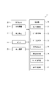
- FIG. 1 is a configuration diagram showing a schematic configuration of a recognition system
- FIG. FIG. 4 is a block diagram relating to control of the recognition system
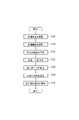
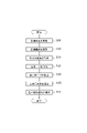
- 4 is a flow chart relating to control of the recognition system
- It is an explanatory view for explaining adjustment of a measurement angle.
- It is a figure which shows the display screen before adjustment of measured distance.
- It is a figure which shows the display screen after adjustment of measured distance.
- It is an explanatory view for explaining reflected light.
- 9 is a flow chart regarding control of the recognition system in the second embodiment.
- FIG. 11 is a configuration diagram showing a schematic configuration of a recognition system in a third embodiment; FIG. FIG. 11 is a flow chart regarding control of the recognition system in the third embodiment; FIG. It is an explanatory view for explaining adjustment of a measurement angle in a 3rd embodiment. It is an explanatory view for explaining reflected light in a 3rd embodiment.
- FIG. 11 is a diagram showing a display screen displaying luminance obtained by measurement in the third embodiment;
- FIG. 11 is a configuration diagram showing a schematic configuration of a recognition system in a fourth embodiment;
- FIG. FIG. 11 is a configuration diagram showing a schematic configuration of a recognition system in a fifth embodiment; It is a block diagram which shows the light absorption member in 5th Embodiment.
- a recognition system 1 is a system having the functions of a three-dimensional measurement system.
- the recognition system 1 is a system for recognizing the position and orientation of a measurement object 41 having a known shape.
- the position and orientation of the measurement object 41 mean the position of the measurement object 41 and the orientation of the measurement object 41 . However, it is not always necessary to recognize both the position and the orientation, and it may be configured to recognize either the position or the orientation.
- the recognition system 1 performs shape measurement by calculating the three-dimensional coordinates of the measurement object 41 imaged using the measurement unit 20 for a plurality of measurement points. Furthermore, the recognition system 1 holds model data, which is data indicating the model shape of the object 41 to be measured. As a result, the recognition system 1 performs position and orientation recognition of the measurement object 41 by matching the three-dimensional coordinates obtained by the shape measurement with the model data. Details of the measurement unit 20 will be described later.
- the recognition system 1 can be used for various tasks using the robot 10. Examples of work using the robot 10 include assembling work of assembling a part to a specific location, picking work of picking a part, visual inspection of inspecting whether a part is flawed or chipped, and gripping work of holding a part. mentioned. However, the recognition system 1 may be used for work that does not use the robot 10 .
- the robot 10 includes a base 11, a robot arm 15, and a robot hand 16.
- the robot 10 is a vertically articulated robot. However, a horizontal articulated robot or the like may be employed as the robot 10 .
- the base 11 is fixed using bolts or the like to the installation surface on which the robot 10 is installed.
- the robot arm 15 is configured by connecting a plurality of shaft parts with joint parts.
- the joint component includes a motor, and the angle of the joint component can be freely controlled by controlling the motor.
- the plurality of shaft components are connected to each other via joint components so as to be relatively rotatable.
- a robot arm 15 is connected to the base 11 .
- the robot hand 16 is attached to the tip of the robot arm 15.
- the robot hand 16 includes a motor.
- the robot hand 16 is configured to be relatively rotatable around the axis of the shaft component provided on the robot arm 15 by controlling the motor.
- the robot hand 16 has claws. This claw portion rotates around the rotation axis of the robot hand 16 .
- the robot hand 16 is configured to be able to grip the measurement object 41 placed on the specular reflection member 31 by opening and closing the gap between the claw portions. Further, the robot 10 can move the robot arm 15 and the robot hand 16 while the robot hand 16 grips the measurement object 41 . Thereby, the position and orientation of the measurement object 41 can be changed. However, in order to grip the measurement object 41, the position and orientation of the measurement object 41 must be accurately recognized.
- the object 41 to be measured is placed on the specular reflection member 31 .
- the specular reflection member 31 has a mirror surface on the upper surface on which the measurement object 41 is placed. Therefore, the light projected onto the specular reflection member 31 is totally reflected. Therefore, the reflection angle can be controlled by controlling the incident angle of the light projected onto the specular reflection member 31 .
- the specular reflection member 31 it is possible to adopt a metal plate, which is a member used for the body of a vehicle and has been mirror-finished by polishing or the like. Specular reflection member 31 provides an example of a reflection member.
- the specular reflection member 31 has a black color that easily absorbs the energy of the projected light. However, when the measurement object 41 and the specular reflection member 31 have the same color, it is difficult to distinguish between the measurement object 41 and the specular reflection member 31 . Therefore, it is preferable to select a color of the specular reflection member 31 that is different from the color of the measurement object 41 and that easily absorbs light energy.
- the specular reflection member 31 is a rectangular plate member.
- the shape of the specular reflection member 31 is not limited to the above example as long as it is sufficiently larger than the measurement object 41 .
- a box-shaped component box having a plate member with a mirror-finished bottom surface laid thereon may be employed as the specular reflection member 31 .
- the number of measurement objects 41 placed on the specular reflection member 31 is not limited to one.
- a plurality of measurement objects 41 may be placed on the specular reflection member 31 while overlapping each other.
- the object 41 to be measured is positioned at a standard position set substantially in the center of the specular reflection member 31, which is the mounting surface.
- a standard position is a standard position where the measurement object 41 is placed.
- An arbitrary shaped object can be adopted as the measurement object 41, but as an example, an object having a shape in which two discs with different diameters are coaxially arranged side by side is adopted.
- the object 41 to be measured is mounted on the specular reflection member 31 so that the disk portion with a small diameter is positioned on the upper side.
- the measurement unit 20 is a device for measuring the shape of the object 41 to be measured.
- the measurement unit 20 has a function of capturing a surface image of the measurement object 41 and a function of calculating a three-dimensional point group of the measurement object 41 .
- a three-dimensional point group is a set of data obtained by calculating the three-dimensional coordinates of the measurement points of the measurement object 41 for a plurality of measurement points.
- a measurement point is each point that expresses the coordinates of the object 41 to be measured.
- a three-dimensional coordinate has an X coordinate, a Y coordinate, and a Z coordinate as coordinate components.
- a distance image sensor that calculates distance using the principle of triangulation such as the phase shift method can be employed.
- the measurement unit 20 is provided in the robot hand 16. Therefore, by controlling the positions of the robot arm 15 and the robot hand 16, the position of the measurement unit 20 can be adjusted.
- control unit 70 that controls the recognition system 1 is connected to the robot 10, the measurement unit 20, and the display device 29.
- the control unit 70 acquires the rotational position and the like of each rotational axis of the robot 10 . Also, the control unit 70 controls the movement of the robot 10 .
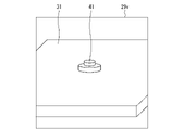
- the display device 29 is a device that displays information regarding position and orientation recognition to the user.
- the display device 29 displays an image captured by the measurement unit 20, for example. By visually recognizing the content displayed on the display device 29, the user can confirm the image pickup range of the measurement unit 20, the brightness of the picked-up image, and the like.
- the control unit 70 controls the presence/absence of display on the display device 29 and the display content.
- the measurement unit 20 includes a light projecting device 21 and a light receiving device 22 .
- a light projection device 21 a projector capable of projecting pattern light used in the phase shift method can be used.
- a device capable of projecting directional light such as laser light can be employed. It is preferable that the light projected from the light projecting device 21 can be distinguished from the light of a fluorescent lamp or sunlight by its intensity and wavelength.
- a camera that captures an image of the measurement object 41 on which pattern light is projected can be used.
- the measurement unit 20 has a light projecting device 21 and a light receiving device 22 housed in one housing. Therefore, the distance between the light projecting device 21 and the light receiving device 22 is always constant.
- the control unit 70 acquires the measurement result of shape measurement by the measurement unit 20 .
- the control section 70 controls the measurement unit 20 to perform shape measurement.
- the control unit 70 includes a position control unit 71 , a data acquisition unit 72 , a data extraction unit 73 , a coordinate calculation unit 75 and a recognition execution unit 79 .
- the position control section 71 controls the position of the measurement unit 20 with respect to the measurement object 41 by controlling the movement of the robot 10 .
- the data acquisition section 72 acquires the measurement result measured by the measurement unit 20 .
- the data extraction unit 73 extracts data used for calculation of the three-dimensional point group from the measurement results acquired by the data acquisition unit 72 .
- the coordinate calculator 75 calculates a three-dimensional point group based on the data extracted by the data extractor 73 .
- the recognition execution unit 79 executes position/orientation recognition by matching the three-dimensional point cloud calculated by the coordinate calculation unit 75 and the model data.
- the control unit 70 includes a robot operation unit 81 and a display control unit 82.
- the robot operation unit 81 performs control such as opening and closing the claw portion of the robot hand 16, and performs picking work and the like.
- the display control unit 82 controls the presence/absence of display on the display device 29 and the display content.
- a measurement angle is an angle of the measurement unit 20 with respect to the specular reflection member 31 . More specifically, the angle of the measurement unit 20 is adjusted so that the projection direction of the measurement unit 20 is not perpendicular to the placement surface, which is the upper surface of the specular reflection member 31 .
- the light projection direction of the measurement unit 20 is inclined by an angle ⁇ from the direction orthogonal to the mounting surface, which is the upper surface of the specular reflection member 31 .
- the projection light PL projected from the measurement unit 20 is totally reflected by the specular reflection member 31 .
- the reflected light RL travels in the direction where the measurement unit 20 does not exist, and does not return to the measurement unit 20 . It can be said that the measurement unit 20 is provided at a position avoiding the traveling direction of the reflected light RL reflected by the specular reflection member 31 .
- the angle ⁇ is not limited to a specific angle. However, if the angle ⁇ is too small, part of the reflected light RL returns to the measurement unit 20, and the luminance based on the reflected light RL is likely to be detected. On the other hand, if the angle ⁇ is too large, the area of the measurement object 41 included in the imaging range tends to be small when the measurement object 41 has a thin shape, and the measurement accuracy tends to decrease. Therefore, it is preferable to adjust the angle so that the measurement accuracy can be as high as possible within a range in which the reflected light RL reflected by the specular reflection member 31 is not measured. After adjusting the measurement angle, the process proceeds to step S102.
- the position control unit 71 adjusts the measured distance.
- the measurement distance is the distance between the measurement unit 20 and the specular reflection member 31 .
- the measurement distance is preferably a distance at which the entire measurement object 41 can be imaged and the background other than the measurement object 41 is as small as possible.
- the display screen 29v displayed on the display device 29 includes components other than the measurement object 41 and the specular reflection member 31.
- the measurement result includes the configuration other than the object 41 to be measured and the specular reflection member 31 . Therefore, it can be said that the distance between the measurement unit 20 and the specular reflection member 31 should be reduced.
- the display screen 29v displayed on the display device 29 does not contain any configuration other than the measurement object 41 and the specular reflection member 31.
- the entire measurement object 41 is contained within the display screen 29v. Therefore, it can be said that the distance between the measurement unit 20 and the specular reflection member 31 is in an appropriate state. After adjusting the measured distance, the process proceeds to step S111.
- step S111 the control unit 70 uses the measurement unit 20 to measure the measurement object 41. More specifically, pattern light such as a striped pattern is projected onto the measurement object 41, and the pattern light reflected by the measurement object 41 is received. At this time, the phase of the projected pattern light is changed to repeat projection and reception. Thereby, the three-dimensional shape of the measurement object 41 is measured from the difference between the projected pattern light and the received pattern light.
- pattern light such as a striped pattern is projected onto the measurement object 41, and the pattern light reflected by the measurement object 41 is received.
- the phase of the projected pattern light is changed to repeat projection and reception. Thereby, the three-dimensional shape of the measurement object 41 is measured from the difference between the projected pattern light and the received pattern light.
- the projection light PL projected from the light projecting device 21 of the measurement unit 20 is partly reflected by the measurement object 41 and the rest is reflected by the specular reflection member 31 .
- the reflected light RL reflected by the measurement object 41 may be referred to as object reflected light RL1
- the reflected light RL reflected by the specular reflection member 31, which is the mounting surface may be referred to as mounting surface reflected light RL2.
- the object-reflected light RL1 diffuses on the surface of the measurement object 41 and spreads in various directions. However, in the drawing, only the object reflected light RL1 directed toward the measurement unit 20 is shown.
- the placement surface reflected light RL2 includes light that is slightly diffused on the surface of the specular reflection member 31, but most of the light is totally reflected and travels in a specific direction. In the drawing, only the placement surface reflected light RL2 totally reflected by the surface of the specular reflection member 31 is shown.
- a part of the energy of the projection light PL projected onto the specular reflection member 31 is absorbed by the specular reflection member 31 .
- the specular reflection member 31 is black, the energy absorbed by the specular reflection member 31 is greater than that of a color such as white. Therefore, even if part of the projection light PL is diffused by the specular reflection member 31, the energy of the diffused light can be easily reduced.
- the light receiving device 22 of the measurement unit 20 receives the object reflected light RL1 to obtain luminance information for each measurement point of the measurement object 41 .
- it since it is provided at a position avoiding the traveling direction of the mounting surface reflected light RL2, it hardly receives the mounting surface reflected light RL2. That is, the energy of the mounting surface reflected light RL2 directed toward the light receiving device 22 is below the lower limit of the light receiving sensitivity of the light receiving device 22, and the luminance obtained by the light receiving device 22 is zero.
- the measurement object 41 and the specular reflection member 31 are displayed within the display screen 29v.
- dots indicate portions where the brightness is zero.
- a portion where the measurement object 41 is displayed has a luminance value higher than zero.
- the brightness of the portion where the specular reflection member 31 is displayed is zero.
- the part where the measurement object 41 is imaged has a luminance higher than zero, and the background part where the measurement object 41 is imaged has zero luminance.
- the data acquisition unit 72 acquires imaging data obtained by measuring the measurement object 41 .
- the imaging data includes two-dimensional coordinates and luminance information for each pixel, which is the minimum unit of an image.
- the imaging data includes a portion where the measurement object 41 is imaged and a portion where the background surrounding the measurement object 41 is imaged.
- object data the portion in which the measurement object 41 is imaged
- background data the portion in which the background around the measurement object 41 is imaged.
- the light receiving device 22 is provided at a position that receives the object reflected light RL1 but does not receive the mounting surface reflected light RL2. For this reason, the object data is made up of pixels whose brightness is higher than zero, and the background data is made up of pixels whose brightness is zero. After acquiring the imaging data, the process proceeds to step S122.
- step S122 the data extraction unit 73 extracts calculation data used to calculate the three-dimensional coordinates of each pixel from the imaging data. More specifically, pixels whose brightness is equal to or higher than the upper limit brightness or equal to or lower than the lower limit brightness are excluded from the imaging data, leaving only pixels exhibiting brightness between the upper limit brightness and the lower limit brightness.
- the light-receiving device 22 detects luminance in 256 steps from zero to 255, the upper limit luminance can be set to 255, which is the saturation luminance, and the lower limit luminance can be set to zero.
- the upper limit luminance should be set to a value that is at least higher than the lower limit luminance.
- the upper limit brightness may be set to a value lower than the saturation brightness
- the lower limit brightness may be set to a value higher than zero.
- the upper limit luminance is set to saturation luminance and the lower limit luminance is set to zero.
- the calculation data does not include background data with a brightness of zero, and only the object data is extracted. After extracting the calculation data, the process proceeds to step S125.
- step S125 the coordinate calculation unit 75 uses the calculation data to calculate a three-dimensional point cloud.
- the calculation data does not include pixels with saturated luminance and pixels with zero luminance.
- the calculation data includes pixels of the target object data, but does not include pixels of the background data. Therefore, although the three-dimensional coordinates of the measurement object 41 are calculated, the three-dimensional coordinates of the background other than the measurement object 41 are not calculated. In other words, the calculated three-dimensional point group does not include three-dimensional coordinates other than those of the measurement object 41 .
- the process proceeds to step S131.
- step S ⁇ b>131 the recognition execution unit 79 executes position and orientation recognition of the measurement object 41 . More specifically, the three-dimensional point cloud of the measurement object 41 and the model data are matched. In matching, the three-dimensional coordinates of a plurality of measurement points included in the three-dimensional point group obtained by shape measurement are matched with the three-dimensional coordinates of a plurality of points included in the model data. For example, after matching the coordinates of a specific point, the coordinates of all points are matched by repeating the process of matching the coordinates of points adjacent to that point. However, since the three-dimensional point cloud contains some errors, it is not necessary to completely match the coordinates of each point. For example, the matching result may be the position and orientation that minimizes the sum of the distances between corresponding points in the model data and the 3D point cloud. After performing the position and orientation recognition, the control related to the position and orientation recognition ends.
- the robot operation unit 81 operates the robot 10 to perform necessary work. More specifically, the robot operation unit 81 performs an operation such as a picking operation on the measurement object 41 whose position and orientation have been recognized. After the work using the robot 10 is completed, if there is another measurement object 41 whose position/orientation should be recognized, control related to position/orientation recognition is repeated.
- the above-described embodiment it is arranged at a position where the brightness of the imaged portion of the specular reflection member 31, which is the placement surface, is equal to or lower than the lower limit brightness. Therefore, it is possible to prevent the reflected light RL received by the light receiving device 22 from including the mounting surface reflected light RL2, which is the light of the background portion. Therefore, the influence of light other than the object reflected light RL1 can be reduced, and the three-dimensional point group of the measurement object 41 can be calculated with high accuracy. Therefore, it is possible to provide a three-dimensional measurement system capable of removing the background with high accuracy.
- the specular reflection member 31 which is a reflection member, is black. Therefore, even if the light is slightly diffused by the mirror surface, the energy of the diffused light can be easily reduced. Therefore, it is difficult for the light receiving device 22 to receive light other than the object reflected light RL1. Therefore, it is easy to suppress erroneous calculation of the three-dimensional coordinates of the measurement object 41 by light other than the object reflected light RL1.
- the light-receiving device 22 is arranged at a position avoiding the traveling direction of the mounting surface reflected light RL2, which is the light reflected by the specular reflecting member 31, which is a reflecting member. Therefore, the background can be removed without performing a process of removing the background from the difference between the background data captured in advance and the captured data. In other words, it can be said that the background is removed from the captured data when the measurement object 41 is captured. Therefore, it is easy to reduce the processing load in background removal and shorten the time required for background removal.
- a display device 29 for displaying the brightness of the imaging data is provided. Therefore, the user can confirm the brightness of the imaging data and perform alignment by adjusting the angle, distance, and the like of the measurement unit 20 .
- the measurement unit 20 is provided in the robot hand 16 of the robot 10. Therefore, the user can perform positioning by controlling the movement of the robot 10 to adjust the angle, distance, etc. of the measurement unit 20 . Therefore, finer adjustments are possible than when the measuring unit 20 is manually adjusted. Further, by storing the appropriate positions of the measurement units 20 in the robot 10, alignment can be completed quickly.
- the brightness of the entire imaging data may be controlled by controlling the length of exposure time.
- the exposure time it is possible to reduce the brightness of the entire imaging data. Therefore, by shortening the exposure time within a range in which the brightness of the portion receiving the object reflected light RL1 does not become zero, the brightness of the entire background portion can be easily made zero.
- the time required for imaging can be shortened, and the time required for completion of position and orientation recognition can be easily shortened.
- the measurement angle is not limited to the above example.
- the measurement angle may be an angle at which only a part of the specular reflection member 31 is imaged and the luminance is equal to or less than the lower limit luminance.
- the object 41 to be measured is mounted at a position of the specular reflection member 31 where the luminance of the mounting surface reflected light RL2 is equal to or less than the lower limit luminance. More specifically, it is assumed that the light projection direction of the measurement unit 20 is orthogonal to the mounting surface of the specular reflection member 31 .
- the intensity of the placement surface reflected light RL2 is highest at the position directly facing the measurement unit 20 in the light projection direction in the specular reflection member 31, and the further away from this position, the more reflected the placement surface.
- the intensity of light RL2 is reduced. Therefore, by placing the measurement object 41 at a position away from the directly facing position, that is, at a position avoiding the center position of the imaging range, the luminance around the measurement object 41 can be partially set to zero. . This makes it possible to reduce the brightness in a part of the background to zero and remove at least part of the background before calculating the 3D point cloud.
- a part of the light reflected by the specular reflection member 31 may be further reflected by the measurement object 41 and received by the light receiving device 22 . Further, part of the light reflected by the measurement object 41 may be further reflected by the specular reflection member 31 and received by the light receiving device 22 .
- the reflected light RL received by the light-receiving device 22 after being reflected multiple times is also called multipath, and is a factor in lowering the accuracy of shape measurement. This multipath is more likely to occur as the distance between the specular reflection member 31 and the measurement object 41 is shorter. For this reason, it is preferable to use a holding component that holds the measurement object 41 in a state of floating from the specular reflection member 31 . According to this, a long distance can be secured between the specular reflection member 31 and the measurement object 41, so that the occurrence of multipath can be easily reduced.
- the retroreflective member 231 forms a mounting surface for mounting the object 41 to be measured.
- the measurement unit 220 is configured with a light projecting device 221 and a light receiving device 222 separately.
- the light projecting device 221 is fixed to the wall using a dedicated jig.
- the light receiving device 222 is provided on the robot hand 16 of the robot 10 . Therefore, by controlling the movement of the robot 10, the position of the light receiving device 222 can be controlled.
- the measurement object 41 is placed on the retroreflective member 231 .
- the retroreflective member 231 is a member having a property of reflecting incident light so that it returns to the incident direction. Therefore, the angle of reflection can be controlled by controlling the incident angle of the light projected onto the retroreflective member 231 .
- a reflecting plate having a plurality of corner cubes which are configured by arranging three flat plates that reflect light in the form of vertices of a cube so as to be orthogonal to each other, can be used.
- a plate member of a retroreflector that reflects incident light in a direction parallel to and opposite to the incident direction may be employed.
- a plate member coated with retroreflective paint may be employed.
- the retroreflective member 231 provides an example of a reflective member.
- the object 41 to be measured and the retroreflective member 231 have the same color, it is difficult to distinguish between the object 41 to be measured and the retroreflective member 231 . Therefore, it is preferable to select a color different from that of the measurement object 41 for the color of the retroreflective member 231 .
- the retroreflective member 231 is a rectangular plate member.
- the shape of the retroreflective member 231 is not limited to the above example as long as it is sufficiently larger than the measurement object 41 .
- a box-shaped parts box having a plate member capable of retroreflecting on the bottom surface may be employed.
- the position control unit 71 adjusts the measurement position in step S201.
- a measurement position is the position of the measurement unit 220 with respect to the retroreflective member 231 . More specifically, the position of the light receiving device 222 is adjusted so that the position of the light receiving device 222 is not positioned on the light projection direction of the light projecting device 221 .
- the light projecting direction of the light projecting device 221 is inclined to some extent from the direction orthogonal to the mounting surface, which is the upper surface of the retroreflective member 231 .
- the light receiving device 222 is positioned directly above the measurement object 41 .
- the projection light PL projected from the light projection device 221 is retroreflected by the retroreflection member 231 .
- the reflected light RL travels in a direction parallel to and opposite to the projection light PL. That is, the reflected light RL travels in a direction where the light receiving device 222 does not exist and does not return to the light receiving device 222 .
- the light receiving device 222 is provided at a position avoiding the traveling direction of the reflected light RL reflected by the retroreflective member 231 .
- step S211 the control unit 70 uses the measurement unit 220 to measure the measurement object 41. More specifically, the three-dimensional shape of the measurement object 41 is measured using the phase shift method.
- the position of the light receiving device 222 with respect to the light projecting device 221 is not always fixed. Therefore, when capturing an image of the measurement object 41, the distance between the light projecting device 221 and the light receiving device 222 is calculated and used for triangulation.
- the projection light PL projected from the light projection device 221 of the measurement unit 220 is partly reflected by the measurement object 41 and the rest is reflected by the retroreflection member 231 .
- the reflected light RL reflected by the retroreflective member 231, which is the mounting surface may be referred to as mounting surface reflected light RL2.
- the object-reflected light RL1 diffuses on the surface of the measurement object 41 and spreads in various directions. However, in the drawing, only the object reflected light RL1 directed toward the measurement unit 220 is shown. On the other hand, although some of the mounting surface reflected light RL2 is slightly diffused on the surface of the retroreflective member 231, most of the light is retroreflected and travels in a specific direction. In the drawing, only the placement surface reflected light RL2 retroreflected by the surface of the retroreflective member 231 is shown.
- the projection light PL projected onto the retroreflective member 231 is reflected by the retroreflective member 231 .
- the reflected light RL travels in a direction parallel to and opposite to the incident direction of the projection light PL, so it does not travel toward the light receiving device 222 but toward the light projecting device 221 .
- the light receiving device 222 receives the object reflected light RL1 to obtain luminance information for each measurement point of the measurement object 41 .
- it hardly receives the mounting surface reflected light RL2. That is, the energy of the mounting surface reflected light RL2 directed toward the light receiving device 222 is below the lower limit of the light receiving sensitivity of the light receiving device 222, and the luminance obtained by the light receiving device 222 is zero.
- the luminance of the portion where the measurement object 41 is imaged is higher than zero, and the luminance of the background portion where the measurement object 41 is imaged is zero.
- step S121 the data acquisition unit 72 acquires imaging data. After that, the process proceeds to step S122, and the data extraction unit 73 extracts calculation data. After that, the process proceeds to step S125, and the coordinate calculation unit 75 calculates a three-dimensional point group. After that, the process proceeds to step S131, and the recognition execution unit 79 executes position and orientation recognition. After completion of the position/orientation recognition, when recognizing another measurement object 41, a series of controls relating to the position/orientation recognition are repeated.
- the light receiving device 222 is arranged at a position avoiding the traveling direction of the mounting surface reflected light RL2, which is the light reflected by the retroreflective member 231.
- FIG. Therefore, it is possible to prevent the reflected light RL received by the light receiving device 222 from including the mounting surface reflected light RL2, which is the light of the background portion. Therefore, the influence of light other than the object reflected light RL1 can be reduced, and the three-dimensional point group of the measurement object 41 can be calculated with high accuracy. Therefore, it is possible to provide a three-dimensional measurement system capable of removing the background with high precision.
- the measurement object 41 is placed on the retroreflective member 231 . Therefore, the mounting surface reflected light RL2 travels parallel to and opposite to the projection light PL. Therefore, various positions can be adopted as the measurement positions that avoid the travel direction of the mounting surface reflected light RL2. In other words, fine angle adjustment is not required for adjustment of the measurement position. Therefore, compared with the case where the object 41 to be measured is placed on the specular reflection member 31, it is easier to start the shape measurement quickly.
- the diffusion member 331 forms a mounting surface for mounting the measurement object 41, and the light receiving device 22 receives the mounting surface reflected light RL2 so that the luminance is equal to or higher than the upper limit luminance.
- the measurement object 41 is placed on the diffusion member 331.
- the diffusing member 331 is a member having a property of diffusing light incident on a surface that provides a mounting surface in various directions.
- a resin member having fine unevenness on its surface can be used.
- the diffusing member 331 for example, a target member used for evaluation tests of cameras and sensors and having a reflectance of 90% or more can be adopted.
- the diffusion member 331 has a white color that does not easily absorb the energy of the projected light. However, when the measurement object 41 and the diffusion member 331 have the same color, it is difficult to distinguish between the measurement object 41 and the diffusion member 331 . Therefore, for the color of the diffusion member 331, it is preferable to select a color that is less likely to absorb light energy among colors different from those of the measurement object 41. FIG.
- the diffusion member 331 is a rectangular plate member.
- the shape of the diffusion member 331 is not limited to the above example as long as it is sufficiently larger than the measurement object 41 .
- a box-shaped component box having a plate member that is processed to facilitate light diffusion on the bottom surface may be employed.
- a measurement angle is an angle of the measurement unit 20 with respect to the diffusion member 331 . More specifically, the angle of the measurement unit 20 is adjusted so that the projection direction of the measurement unit 20 is substantially orthogonal to the mounting surface, which is the upper surface of the diffusion member 331 .
- the light projection direction of the measurement unit 20 is perpendicular to the mounting surface, which is the upper surface of the diffusion member 331 .
- the projection light PL projected from the measurement unit 20 is diffused in various directions by the diffusion member 331, and the intensity of the reflected light RL is high over a wide range.
- the reflected light RL is likely to return to the position of the measurement unit 20 .
- the intensity of the reflected light RL is highest at the position where the projection light PL is projected, and the intensity of the reflected light RL decreases with increasing distance from the position where the projection light PL is projected.
- the measurement angle of the measurement unit 20 can also be said to be the angle at which the brightness becomes highest when the reflected light RL is received. In the figure, the reflected light toward the measurement unit 20 Only RL is shown.
- the position can be adjusted so that most of the reflected light RL reflected by the diffusion member 331 returns to the measurement unit 20.
- the light projection direction of the measurement unit 20 may adopt an angle slightly inclined from the angle orthogonal to the mounting surface.
- the light projecting device 21 and the light receiving device 22 may be configured separately, and only the angle of the light receiving device 22 may be adjusted. After adjusting the measurement angle, the process proceeds to step S102.
- step S102 the position control unit 71 adjusts the measured distance. As a result, the entire measurement object 41 can be imaged, and the distance is adjusted so that the background other than the measurement object 41 is as small as possible. After that, the process proceeds to step S311.
- step S311 the control unit 70 uses the measurement unit 20 to measure the measurement object 41. More specifically, the three-dimensional shape of the measurement object 41 is measured using the phase shift method.
- the projection light PL projected from the light projecting device 21 of the measurement unit 20 is partly reflected by the measurement object 41 and the rest is diffused by the diffusion member 331 .
- the reflected light RL reflected so as to be diffused by the diffusion member 331, which is the mounting surface may be referred to as mounting surface reflected light RL2.
- the object-reflected light RL1 diffuses on the surface of the measurement object 41 and spreads in various directions. However, the angle of the measurement unit 20 is controlled to the measurement angle, and the brightness of the portion receiving the object reflected light RL1 is lower than the upper limit brightness. In the drawing, only the object reflected light RL1 directed toward the measurement unit 20 is shown.
- the angle of the measurement unit 20 is controlled to the measurement angle, and the luminance of the portion receiving the mounting surface reflected light RL2 is equal to or higher than the upper limit luminance. In the drawing, only the placement surface reflected light RL2 directed toward the measurement unit 20 is shown.
- a part of the energy of the projection light PL projected onto the diffusion member 331 is absorbed by the diffusion member 331 .
- the diffusion member 331 is white, the energy absorbed by the diffusion member 331 is smaller than that of a color such as black. Therefore, it is easy to increase the energy of the light diffused by the diffusion member 331 .
- the light receiving device 22 of the measurement unit 20 receives the mounting surface reflected light RL2 to obtain information on the brightness of the diffusion member 331 .
- the energy of the mounting surface reflected light RL2 directed toward the light receiving device 22 exceeds the upper limit of the light receiving sensitivity of the light receiving device 22, and the luminance obtained by the light receiving device 22 is saturated luminance.
- the light receiving device 22 receives the object reflected light RL ⁇ b>1 and obtains luminance information for each measurement point of the measurement object 41 . At this time, the luminance obtained by the light receiving device 22 is lower than the saturation luminance.
- the measurement object 41 and the diffusion member 331 are displayed within the display screen 29v.
- dots indicate portions where the luminance is saturated luminance.
- the luminance around the measurement object 41 is saturated luminance.
- the luminance is high at a position far away from the measurement object 41, but does not reach the saturation luminance.
- the portion where the measurement object 41 is displayed has a value lower than the saturation luminance. This is because the projection light PL projected onto the measurement object 41 is not diffused by the diffusion member 331 and is reflected by the measurement object 41 .
- the luminance of the portion where the measurement object 41 is imaged is lower than the saturation luminance, and the luminance of at least a part of the background portion where the measurement object 41 is imaged is the saturation luminance. More specifically, the luminance of the portion of the diffusion member 331 that receives the placement surface reflected light RL2 reflected at the standard position reaches saturation luminance.
- the size of the region where the luminance of the portion receiving the mounting surface reflected light RL2 becomes saturated luminance can be controlled by adjusting the exposure time. That is, the longer the exposure time, the greater the amount of light received by the light-receiving device 22, so that the brightness tends to increase, and the region of saturated brightness can be expanded. However, since increasing the exposure time tends to increase the brightness of the portion receiving the object-reflected light RL1, the exposure time is adjusted within a range in which the brightness of the portion receiving the object-reflected light RL1 does not become saturated. is preferred. After measuring the measurement object 41, the process proceeds to step S121.
- step S121 the data acquisition unit 72 acquires imaging data.
- step S122 the data extraction unit 73 extracts calculation data.
- the extracted calculation data does not include pixels whose luminance has reached the saturation luminance set to the upper limit luminance.
- the calculation data includes only the measurement object 41 and the background at a position away from the measurement object 41 .
- step S125 the coordinate calculation unit 75 extracts a three-dimensional point group.
- the recognition execution unit 79 executes position and orientation recognition. After completion of the position/orientation recognition, when recognizing another measurement object 41, a series of controls relating to the position/orientation recognition are repeated.
- the light-receiving device 22 has a luminance lower than the upper limit luminance in the portion where the measurement object 41 is imaged, and a luminance higher than the upper limit luminance in the portion where the diffusion member 331 serving as the placement surface is imaged. It is placed at a position that provides brightness. Therefore, among the reflected light RL received by the light-receiving device 22, the luminance of the placement surface reflected light RL2, which is the light of the background portion, can easily be made equal to or higher than the saturation luminance.
- the three-dimensional point group of the measurement object 41 can be calculated with high accuracy by calculating the three-dimensional point group while excluding the luminance equal to or higher than the saturation luminance. Therefore, it is possible to provide a three-dimensional measurement system capable of removing the background with high accuracy.
- the diffusion member 331 is white. For this reason, the light projected onto the diffusing member 331 is less likely to be absorbed, that is, the high energy state of the mounting surface reflected light RL2 can be easily maintained. Therefore, the luminance of the portion receiving the mounting surface reflected light RL2 can easily be saturated. Therefore, the energy of the light reflected by the diffusing member 331 can be kept high, and it is easy to ensure a large portion of saturated luminance.
- This embodiment is also a modification based on the preceding embodiment. In particular, it solves the multipath problem described in the first embodiment.
- the measurement object 41 is held by a holding base 400 as shown in FIG.
- the holding table 400 has a mounting surface supported by four legs 401 .
- the mounting surface has a metal honeycomb mesh structure that can sufficiently withstand the weight of the measurement object 41 to be held.
- it is made of aluminum or an aluminum alloy.
- the mesh structure is coated with black paint that absorbs light.
- a specular reflection member 403 is arranged below the holding table 400 having a mesh structure.
- the holding table 400 and the specular reflection member 403 have a predetermined angle so that the light that passes through the mounting surface and is reflected by the specular reflection member 403 does not return to the holding table 400 again.
- the specular reflection member 403 is a black reflector that totally reflects light, like the specular reflection member 31 of the first embodiment. As a result, the light PL ⁇ b>1 that is not directed toward the measurement object 41 out of the projection light PL passes through the holding table 400 and is reflected by the specular reflection member 403 in a direction that is not directed toward the measurement unit 20 .
- the light projecting device 21 of the measurement unit 20 of the fourth embodiment is set to project near-infrared light PL of about 900 nanometers.
- the light receiving device 22 also receives the reflected light RL having the frequency of the projection light PL projected from the light projecting device 21 .
- a space 402 indicated by a dashed line in FIG. 18 indicates the measurement range of the measurement unit 20 . That is, the projection light PL from the light projecting device 21 is projected onto this space 402 , and the reflected light RL from this space 402 is directed toward the light receiving device 22 .
- the holding table 400 since the holding table 400 has a mesh structure, the projection light PL passes through it. Moreover, since the holding table 400 having a mesh structure is painted matte black, the problem of multipath due to the holding table 400 does not occur. Projection light PL1 that has passed through the mesh structure is reflected by specular reflection member 403 in a direction that does not return to holding table 400 of mesh structure. I will never go back. That is, only the reflected light RL ⁇ b>1 from the measurement object 41 is incident on the measurement unit 20 . Therefore, the problem of multipath caused by the projection light PL that has passed through the placement surface does not occur.
- Near-infrared components are included in outdoor natural light, but the measurement unit 20 is installed indoors. Therefore, in the environment in which the measurement unit 20 is installed, the ambient light does not normally have a near-infrared light component. Therefore, even if ambient light is reflected by the specular reflection member 403 and directed toward the light receiving device 22 of the measurement unit 20, the light receiving device 22 does not detect the ambient light. As a result, ambient light does not become a disturbance factor, and the measurement unit 20 can perform accurate measurements.
- the fifth embodiment is also a modification of the preceding embodiment as a basic form.
- a light absorbing member 500 is used on the mounting surface.
- an incident angle filter 501 and a diffuse reflection material 502 are arranged with a predetermined interval.
- the incident angle filter 501 has the property of passing only the projection light PL incident directly and reflecting the incident light with an angle.
- the measurement object 41 is placed on this incident angle filter 501 .
- the incident angle filter 501 is shown in a planar shape, but it has a bowl-shaped cross section with an arc centered on the light projecting device 21 so that the projection light PL that is incident directly can pass through. .
- the diffuse reflection material 502 diffuses the light incident on the front and does not reflect it in the front direction. Therefore, it is possible to effectively prevent the projection light PL that has passed through the incident angle filter 501 from passing through the incident angle filter 501 again and becoming the mounting surface reflected light RL. In other words, the projection light PL striking the mounting surface made of the light absorbing member 500 is confined between the incident angle filter 501 of the mounting surface and the diffuse reflection material 502 and is not reflected toward the measurement unit 20 side.
- the projection light PL only the object-reflected light RL1 that is directed toward the measurement object 41 and reflected by the measurement object 41 is directed toward the light receiving device 22 as the directly facing direction.
- the light PL1 that travels toward the portion 504 that does not travel toward the measurement object 41 does not become the reflected light RL.
- Metamaterial member may be used as the light absorbing member 500 . Metamaterial members can also have very low reflectivity properties.
- the controller and techniques described in this disclosure may be implemented by a special purpose computer comprising a processor programmed to perform one or more functions embodied by a computer program.
- the apparatus and techniques described in this disclosure may be implemented by dedicated hardware logic circuitry.
- the apparatus and techniques described in this disclosure may be implemented by one or more special purpose computers configured by a combination of a processor executing a computer program and one or more hardware logic circuits.
- the computer program may also be stored as computer-executable instructions on a computer-readable non-transitional tangible recording medium.
Landscapes
- Engineering & Computer Science (AREA)
- Physics & Mathematics (AREA)
- General Physics & Mathematics (AREA)
- Computer Vision & Pattern Recognition (AREA)
- Robotics (AREA)
- Mechanical Engineering (AREA)
- Optics & Photonics (AREA)
- Theoretical Computer Science (AREA)
- Length Measuring Devices By Optical Means (AREA)
Abstract
Description
計測対象物に投影光を投光する投光装置と、投影光が反射した光である反射光を受光する受光装置とを有し、計測対象物を撮像する計測ユニットと、
計測対象物を載置するための載置面をなし、投影光を特定の角度で反射する反射部材と、
計測ユニットを用いて撮像した撮像データを取得するデータ取得部と、
撮像データの内、輝度が下限輝度よりも高い部分については三次元座標を算出し、輝度が下限輝度以下の部分については三次元座標を算出しない座標算出部とを備え、
受光装置は、反射部材を撮像した部分の輝度が下限輝度以下となる位置に配置されている。 The three-dimensional measurement system disclosed here is a three-dimensional measurement system that performs shape measurement for measuring the three-dimensional shape of a measurement object,
a measurement unit that captures an image of a measurement object, the measurement unit having a light projection device that projects projection light onto a measurement object and a light reception device that receives reflected light that is light reflected from the projection light;
a reflecting member that forms a mounting surface for mounting the object to be measured and reflects projected light at a specific angle;
a data acquisition unit that acquires imaging data captured using the measurement unit;
a coordinate calculation unit that calculates three-dimensional coordinates for a portion of imaging data with luminance higher than the lower limit luminance and does not calculate three-dimensional coordinates for a portion with luminance equal to or lower than the lower limit luminance,
The light-receiving device is arranged at a position where the brightness of the part where the reflection member is imaged is equal to or lower than the lower limit brightness.
計測対象物に投影光を投光する投光装置と、投影光が反射した光である反射光を受光する受光装置とを有し、計測対象物を撮像する計測ユニットと、
計測対象物を載置するための載置面をなし、投影光を拡散する拡散部材と、
計測ユニットを用いて撮像した撮像データを取得するデータ取得部と、
撮像データの内、輝度が上限輝度よりも低い部分については三次元座標を算出し、輝度が上限輝度以上の部分については三次元座標を算出しない座標算出部とを備え、受光装置は、拡散部材を撮像した部分の輝度が上限輝度以上となる位置に配置されている。 Further, the three-dimensional measurement system disclosed herein is a three-dimensional measurement system that performs shape measurement for measuring the three-dimensional shape of a measurement object,
a measurement unit that captures an image of a measurement object, the measurement unit having a light projection device that projects projection light onto a measurement object and a light reception device that receives reflected light that is light reflected from the projection light;
a diffusing member that forms a mounting surface for mounting the object to be measured and diffuses the projected light;
a data acquisition unit that acquires imaging data captured using the measurement unit;
a coordinate calculation unit that calculates three-dimensional coordinates for a portion of the imaging data whose luminance is lower than the upper limit luminance, and does not calculate the three-dimensional coordinates for a portion whose luminance is equal to or higher than the upper limit luminance; is arranged at a position where the luminance of the imaged portion is equal to or higher than the upper limit luminance.
図1において、認識システム1は、三次元計測システムの機能を備えたシステムである。認識システム1は、既知の形状である計測対象物41の位置姿勢を認識するためのシステムである。計測対象物41の位置姿勢とは、計測対象物41の位置および計測対象物41の姿勢を意味する。ただし、必ずしも位置と姿勢の両方を認識する必要はなく、位置と姿勢のどちらか一方を認識する構成としてもよい。 First Embodiment In FIG. 1, a
この実施形態は、先行する実施形態を基礎的形態とする変形例である。この実施形態では、再帰反射部材231が計測対象物41を載置するための載置面をなしている。 Second Embodiment This embodiment is a modification based on the preceding embodiment. In this embodiment, the
この実施形態は、先行する実施形態を基礎的形態とする変形例である。この実施形態では、拡散部材331が計測対象物41を載置するための載置面をなしており、受光装置22が載置面反射光RL2を上限輝度以上の輝度となるように受光している。 Third Embodiment This embodiment is a modification based on the preceding embodiment. In this embodiment, the
拡散し、広範囲にわたって反射光RLの強度が高い状態となる。ただし、投光方向は拡散部材331の載置面に直交しているため、反射光RLは、計測ユニット20の位置に戻ってくる可能性が高い。言い換えると、投影光PLが投光されている位置における反射光RLの強度が最も高く、投影光PLが投光されている位置から離れるほど、反射光RLの強度が低下する。計測ユニット20の計測角度は、反射光RLを受光した際の輝度が最も高くなる角度とも言える。図においては、計測ユニット20に向かう反射光
RLのみを図示している。 In FIG. 15 , the light projection direction of the
Only RL is shown.
よって、高精度に背景を除去可能な三次元計測システムを提供できる。 The effects of the above-described embodiment will be described below. According to the above-described embodiment, the light-receiving
Therefore, it is possible to provide a three-dimensional measurement system capable of removing the background with high accuracy.
この実施形態も、先行する実施形態を基礎的形態とする変形例である。特に、第1実施形態で説明したマルチパスに対する課題を解決するものである。 Fourth Embodiment This embodiment is also a modification based on the preceding embodiment. In particular, it solves the multipath problem described in the first embodiment.
第5実施形態も、先行する実施形態を基礎的形態とする変形例で、この第5実施形態では、図19に示すように載置面に光吸収部材500を用いている。 Fifth Embodiment The fifth embodiment is also a modification of the preceding embodiment as a basic form. In this fifth embodiment, as shown in FIG. 19, a
この明細書および図面等における開示は、例示された実施形態に制限されない。開示は、例示された実施形態と、それらに基づく当業者による変形態様を包含する。例えば、開示は、実施形態において示された部品および/または要素の組み合わせに限定されない。開示は、多様な組み合わせによって実施可能である。開示は、実施形態に追加可能な追加的な部分をもつことができる。開示は、実施形態の部品および/または要素が省略されたものを包含する。開示は、1つの実施形態と他の実施形態との間における部品および/または要素の置き換え、または組み合わせを包含する。開示される技術的範囲は、実施形態の記載に限定されない。開示されるいくつかの技術的範囲は、請求の範囲の記載によって示され、さらに請求の範囲の記載と均等の意味および範囲内での全ての変更を含むものと解されるべきである。 Other Embodiments The disclosures in this specification, drawings, etc. are not limited to the illustrated embodiments. The disclosure encompasses the illustrated embodiments and variations thereon by those skilled in the art. For example, the disclosure is not limited to the combinations of parts and/or elements shown in the embodiments. The disclosure can be implemented in various combinations. The disclosure can have additional parts that can be added to the embodiments. The disclosure encompasses omitting parts and/or elements of the embodiments. The disclosure encompasses permutations or combinations of parts and/or elements between one embodiment and another. The disclosed technical scope is not limited to the description of the embodiments. The disclosed technical scope is indicated by the description of the claims, and should be understood to include all changes within the meaning and range of equivalents to the description of the claims.
The controller and techniques described in this disclosure may be implemented by a special purpose computer comprising a processor programmed to perform one or more functions embodied by a computer program. Alternatively, the apparatus and techniques described in this disclosure may be implemented by dedicated hardware logic circuitry. Alternatively, the apparatus and techniques described in this disclosure may be implemented by one or more special purpose computers configured by a combination of a processor executing a computer program and one or more hardware logic circuits. The computer program may also be stored as computer-executable instructions on a computer-readable non-transitional tangible recording medium.
Claims (11)
- 計測対象物(41)の三次元形状を計測するための形状計測を行う三次元計測システムであって、
前記計測対象物に投影光(PL)を投光する投光装置(21、221)と、前記投影光が反射した光である反射光(RL)を受光する受光装置(22、222)とを有し、前記計測対象物を撮像する計測ユニット(20、220)と、
前記計測対象物を載置するための載置面をなし、前記投影光を特定の角度で反射する反射部材(31、231)と、
前記計測ユニットを用いて撮像した撮像データを取得するデータ取得部(72)と、
前記撮像データの内、輝度が下限輝度よりも高い部分については三次元座標を算出し、輝度が前記下限輝度以下の部分については前記三次元座標を算出しない座標算出部(75)とを備え、
前記受光装置は、前記反射部材を撮像した部分の輝度が前記下限輝度以下となる位置に配置されている三次元計測システム。 A three-dimensional measurement system that performs shape measurement for measuring the three-dimensional shape of a measurement object (41),
A light projecting device (21, 221) for projecting projection light (PL) onto the measurement object, and a light receiving device (22, 222) for receiving reflected light (RL), which is light reflected from the projection light. a measurement unit (20, 220) for capturing an image of the object to be measured;
a reflecting member (31, 231) that forms a mounting surface for mounting the measurement object and reflects the projection light at a specific angle;
a data acquisition unit (72) for acquiring imaging data captured using the measurement unit;
A coordinate calculation unit (75) that calculates three-dimensional coordinates for a portion of the imaging data whose luminance is higher than the lower limit luminance and does not calculate the three-dimensional coordinates for a portion whose luminance is equal to or less than the lower limit luminance,
The three-dimensional measurement system, wherein the light-receiving device is arranged at a position where the brightness of the imaged portion of the reflecting member is equal to or lower than the lower-limit brightness. - 前記反射部材は、黒色である請求項1に記載の三次元計測システム。 The three-dimensional measurement system according to claim 1, wherein the reflecting member is black.
- 前記反射部材は、前記投影光を全反射する鏡面反射部材(31)であって、
前記受光装置は、前記投影光が前記鏡面反射部材で反射した光である載置面反射光(RL2)の進行方向を避けた位置に配置されている請求項1または請求項2に記載の三次元計測システム。 The reflecting member is a specular reflecting member (31) that totally reflects the projection light,
3. The tertiary according to claim 1 or 2, wherein the light receiving device is arranged at a position avoiding the traveling direction of the mounting surface reflected light (RL2), which is the light reflected by the specular reflection member from the projection light. Yuan measurement system. - 前記反射部材は、前記投影光を再帰反射する再帰反射部材(231)であって、
前記受光装置は、前記投影光が前記再帰反射部材で反射した光である載置面反射光(RL2)の進行方向を避けた位置に配置されている請求項1に記載の三次元計測システム。 The reflective member is a retroreflective member (231) that retroreflects the projection light,
2. The three-dimensional measurement system according to claim 1, wherein the light receiving device is arranged at a position avoiding the traveling direction of the mounting surface reflected light (RL2), which is the light reflected by the retroreflective member. - 計測対象物(41)の三次元形状を計測するための形状計測を行う三次元計測システムであって、
前記計測対象物に投影光(PL)を投光する投光装置(21)と、前記投影光が反射した光である反射光(RL)を受光する受光装置(22)とを有し、前記計測対象物を撮像する計測ユニット(20)と、
前記計測対象物を載置するための載置面をなし、前記投影光を拡散する拡散部材(331)と、
前記計測ユニットを用いて撮像した撮像データを取得するデータ取得部(72)と、
前記撮像データの内、輝度が上限輝度よりも低い部分については三次元座標を算出し、輝度が前記上限輝度以上の部分については前記三次元座標を算出しない座標算出部(75)とを備え、
前記受光装置は、前記拡散部材を撮像した部分の輝度が前記上限輝度以上となる位置に配置されている三次元計測システム。 A three-dimensional measurement system that performs shape measurement for measuring the three-dimensional shape of a measurement object (41),
a light projecting device (21) for projecting projected light (PL) onto the measurement object, and a light receiving device (22) for receiving reflected light (RL), which is light reflected by the projected light, a measurement unit (20) that captures an image of an object to be measured;
a diffusing member (331) forming a mounting surface for mounting the measurement object and diffusing the projection light;
a data acquisition unit (72) for acquiring imaging data captured using the measurement unit;
a coordinate calculation unit (75) that calculates three-dimensional coordinates for a portion of the imaging data whose luminance is lower than the upper limit luminance and does not calculate the three-dimensional coordinates for a portion whose luminance is equal to or higher than the upper limit luminance,
The three-dimensional measurement system, wherein the light-receiving device is arranged at a position where the brightness of the imaged portion of the diffusion member is equal to or higher than the upper limit brightness. - 前記拡散部材は、白色である請求項5に記載の三次元計測システム。 The three-dimensional measurement system according to claim 5, wherein the diffusion member is white.
- 前記撮像データの輝度を表示する表示装置(29)を備えている請求項1から請求項6のいずれかに記載の三次元計測システム。 The three-dimensional measurement system according to any one of claims 1 to 6, further comprising a display device (29) for displaying the brightness of the imaging data.
- 計測対象物(41)の三次元形状を計測するための形状計測を行う三次元計測システムであって、
前記計測対象物に近赤外線の投影光(PL)を投光する投光装置(21、221)と、前記投影光が反射した光である近赤外線の反射光(RL)を受光する受光装置(22、222)とを有し、前記計測対象物を撮像する計測ユニット(20、220)と、
前記計測対象物を載置するための載置面をなし、前記投影光が通過可能なメッシュ構造の保持台(400)と、このメッシュ構造体を通過した光を前記メッシュ構造体には戻らない方向に反射する反射部材(403)と、
前記計測ユニットを用いて撮像した撮像データを取得するデータ取得部(72)と、
前記撮像データの内、輝度が下限輝度よりも高い部分については三次元座標を算出し、輝度が前記下限輝度以下の部分については前記三次元座標を算出しない座標算出部(75)とを備える三次元計測システム。 A three-dimensional measurement system that performs shape measurement for measuring the three-dimensional shape of a measurement object (41),
A light projecting device (21, 221) that projects near-infrared projected light (PL) onto the measurement object, and a light receiving device ( 22, 222) for imaging the object to be measured (20, 220);
A holding table (400) having a mesh structure that forms a mounting surface for mounting the measurement object and allows the projection light to pass through, and a light that has passed through the mesh structure does not return to the mesh structure. a reflective member (403) that reflects in a direction;
a data acquisition unit (72) for acquiring imaging data captured using the measurement unit;
a coordinate calculation unit (75) that calculates three-dimensional coordinates for a portion of the imaging data whose luminance is higher than the lower limit luminance and does not calculate the three-dimensional coordinates for a portion of the luminance that is equal to or lower than the lower limit luminance; Yuan measurement system. - 前記メッシュ構造体は、艶消しの黒色に塗装されている請求項8記載の三次元計測システム。 The three-dimensional measurement system according to claim 8, wherein the mesh structure is painted matte black.
- 計測対象物(41)の三次元形状を計測するための形状計測を行う三次元計測システムであって、
前記計測対象物に投影光(PL)を投光する投光装置(21、221)と、前記投影光が反射した光である反射光(RL)を受光する受光装置(22、222)とを有し、前記計測対象物を撮像する計測ユニット(20、220)と、
前記計測対象物を載置するための載置面をなし、前記投影光を吸収する光吸収部材(500)と、
前記計測ユニットを用いて撮像した撮像データを取得するデータ取得部(72)と、
前記撮像データの内、輝度が下限輝度よりも高い部分については三次元座標を算出し、輝度が前記下限輝度以下の部分については前記三次元座標を算出しない座標算出部(75)とを備える三次元計測システム。
A three-dimensional measurement system that performs shape measurement for measuring the three-dimensional shape of a measurement object (41),
A light projecting device (21, 221) for projecting projection light (PL) onto the measurement object, and a light receiving device (22, 222) for receiving reflected light (RL), which is light reflected from the projection light. a measurement unit (20, 220) for capturing an image of the object to be measured;
a light absorbing member (500) that forms a mounting surface for mounting the measurement object and absorbs the projection light;
a data acquisition unit (72) for acquiring imaging data captured using the measurement unit;
a coordinate calculation unit (75) that calculates three-dimensional coordinates for a portion of the imaging data whose luminance is higher than the lower limit luminance and does not calculate the three-dimensional coordinates for a portion of the luminance that is equal to or lower than the lower limit luminance; Yuan measurement system.
- 前記光吸収部材は、正対入射する投影光PLのみ通過して角度の付いた入射光は反射する性質を有する入射角度フィルタ(501)と、正対入射した光を拡散させ正対方向には反射させない性質を有する拡散反射素材(502)とを、所定の間隔を空けて配置している請求項10記載の三次元計測システム。 The light absorbing member includes an incident angle filter (501) having a property of transmitting only the projection light PL incident directly and reflecting the incident light with an angle, 11. The three-dimensional measurement system according to claim 10, wherein a diffuse reflection material (502) having non-reflecting properties is arranged at a predetermined interval.
Priority Applications (4)
| Application Number | Priority Date | Filing Date | Title |
|---|---|---|---|
| EP22759171.6A EP4300035A4 (en) | 2021-02-24 | 2022-01-20 | Three-dimensional measurement system |
| JP2023502167A JPWO2022181128A1 (en) | 2021-02-24 | 2022-01-20 | |
| CN202280007666.2A CN116490745A (en) | 2021-02-24 | 2022-01-20 | Three-dimensional measuring system |
| US18/278,793 US20240151518A1 (en) | 2021-02-24 | 2022-01-20 | Three-dimensional measurement system |
Applications Claiming Priority (2)
| Application Number | Priority Date | Filing Date | Title |
|---|---|---|---|
| JP2021027774 | 2021-02-24 | ||
| JP2021-027774 | 2021-02-24 |
Publications (1)
| Publication Number | Publication Date |
|---|---|
| WO2022181128A1 true WO2022181128A1 (en) | 2022-09-01 |
Family
ID=83049082
Family Applications (1)
| Application Number | Title | Priority Date | Filing Date |
|---|---|---|---|
| PCT/JP2022/001942 WO2022181128A1 (en) | 2021-02-24 | 2022-01-20 | Three-dimensional measurement system |
Country Status (5)
| Country | Link |
|---|---|
| US (1) | US20240151518A1 (en) |
| EP (1) | EP4300035A4 (en) |
| JP (1) | JPWO2022181128A1 (en) |
| CN (1) | CN116490745A (en) |
| WO (1) | WO2022181128A1 (en) |
Citations (9)
| Publication number | Priority date | Publication date | Assignee | Title |
|---|---|---|---|---|
| JPS58169762A (en) * | 1982-03-30 | 1983-10-06 | Internatl Precision Inc | Electron beam device |
| JPH0798213A (en) * | 1993-08-31 | 1995-04-11 | Nippon Steel Corp | Method and device for object recognition by image processing |
| JPH11251794A (en) * | 1998-03-02 | 1999-09-17 | Sony Corp | Electronic component mounting apparatus |
| JP3063382U (en) * | 1999-04-26 | 1999-10-29 | 株式会社アイアンドデイ | Background body in photography equipment |
| JP2000065547A (en) * | 1998-08-18 | 2000-03-03 | Daihatsu Motor Co Ltd | Shape measurement device for black-work and extraction device thereof |
| JP2003098120A (en) * | 2001-09-26 | 2003-04-03 | Tokyo Weld Co Ltd | Visual inspection apparatus |
| JP2007102718A (en) * | 2005-10-07 | 2007-04-19 | Saibuaasu:Kk | Background image separation device and system |
| WO2013187202A1 (en) * | 2012-06-12 | 2013-12-19 | 株式会社島精機製作所 | Three-dimensional measurement apparatus, and three-dimensional measurement method |
| JP2019145177A (en) | 2014-04-28 | 2019-08-29 | キヤノン株式会社 | Image processing method and imaging device |
Family Cites Families (1)
| Publication number | Priority date | Publication date | Assignee | Title |
|---|---|---|---|---|
| CN102980513B (en) * | 2012-11-02 | 2016-01-20 | 浙江工业大学 | Monocular full-view stereo vision sensor centered by thing |
-
2022
- 2022-01-20 EP EP22759171.6A patent/EP4300035A4/en active Pending
- 2022-01-20 JP JP2023502167A patent/JPWO2022181128A1/ja active Pending
- 2022-01-20 US US18/278,793 patent/US20240151518A1/en active Pending
- 2022-01-20 CN CN202280007666.2A patent/CN116490745A/en active Pending
- 2022-01-20 WO PCT/JP2022/001942 patent/WO2022181128A1/en active Application Filing
Patent Citations (9)
| Publication number | Priority date | Publication date | Assignee | Title |
|---|---|---|---|---|
| JPS58169762A (en) * | 1982-03-30 | 1983-10-06 | Internatl Precision Inc | Electron beam device |
| JPH0798213A (en) * | 1993-08-31 | 1995-04-11 | Nippon Steel Corp | Method and device for object recognition by image processing |
| JPH11251794A (en) * | 1998-03-02 | 1999-09-17 | Sony Corp | Electronic component mounting apparatus |
| JP2000065547A (en) * | 1998-08-18 | 2000-03-03 | Daihatsu Motor Co Ltd | Shape measurement device for black-work and extraction device thereof |
| JP3063382U (en) * | 1999-04-26 | 1999-10-29 | 株式会社アイアンドデイ | Background body in photography equipment |
| JP2003098120A (en) * | 2001-09-26 | 2003-04-03 | Tokyo Weld Co Ltd | Visual inspection apparatus |
| JP2007102718A (en) * | 2005-10-07 | 2007-04-19 | Saibuaasu:Kk | Background image separation device and system |
| WO2013187202A1 (en) * | 2012-06-12 | 2013-12-19 | 株式会社島精機製作所 | Three-dimensional measurement apparatus, and three-dimensional measurement method |
| JP2019145177A (en) | 2014-04-28 | 2019-08-29 | キヤノン株式会社 | Image processing method and imaging device |
Non-Patent Citations (1)
| Title |
|---|
| See also references of EP4300035A4 |
Also Published As
| Publication number | Publication date |
|---|---|
| US20240151518A1 (en) | 2024-05-09 |
| JPWO2022181128A1 (en) | 2022-09-01 |
| EP4300035A4 (en) | 2024-08-07 |
| EP4300035A1 (en) | 2024-01-03 |
| CN116490745A (en) | 2023-07-25 |
Similar Documents
| Publication | Publication Date | Title |
|---|---|---|
| US9448059B2 (en) | Three-dimensional scanner with external tactical probe and illuminated guidance | |
| Li et al. | Automatic recalibration of an active structured light vision system | |
| CN105190232A (en) | Three-dimensional coordinate scanner and method of operation | |
| CN110296667A (en) | High reflection surface method for three-dimensional measurement based on line-structured light multi-angle projection | |
| US20150015701A1 (en) | Triangulation scanner having motorized elements | |
| US20150178412A1 (en) | Three-dimensional coordinate scanner and method of operation | |
| CN107764834B (en) | Device for automatically detecting surface defects of transparent part and detection method thereof | |
| US20130057650A1 (en) | Optical gage and three-dimensional surface profile measurement method | |
| JP2005258810A5 (en) | ||
| CN105190235A (en) | Compensation of a structured light scanner that is tracked in six degrees-of-freedom | |
| EP3743713B1 (en) | Vehicle surface scanning system | |
| JP4740826B2 (en) | Shape measuring device and shape measuring method | |
| CN105953742A (en) | 3D laser scanner based on unknown environment detection | |
| JP4743771B2 (en) | Section data acquisition method, system, and section inspection method | |
| US20060001760A1 (en) | Apparatus and method for object shape detection | |
| CN103206926A (en) | Panorama three-dimensional laser scanner | |
| KR20210002821A (en) | Large reflector 3D surface shape measuring method by using Fringe Pattern Reflection Technique | |
| CN115682937A (en) | Calibration method of automatic three-dimensional laser scanner | |
| Moller et al. | An automatic evaluation procedure for 3-D scanners in robotics applications | |
| JP2018522240A (en) | Method for measuring artifacts | |
| WO2022181128A1 (en) | Three-dimensional measurement system | |
| JP2010256151A (en) | Shape measuring method | |
| JP2015010845A5 (en) | ||
| JP2013096784A (en) | Surface characteristic measuring device and computer program | |
| JP5291140B2 (en) | Shape measuring device and shape measuring method |
Legal Events
| Date | Code | Title | Description |
|---|---|---|---|
| 121 | Ep: the epo has been informed by wipo that ep was designated in this application |
Ref document number: 22759171 Country of ref document: EP Kind code of ref document: A1 |
|
| WWE | Wipo information: entry into national phase |
Ref document number: 202280007666.2 Country of ref document: CN |
|
| WWE | Wipo information: entry into national phase |
Ref document number: 2023502167 Country of ref document: JP |
|
| WWE | Wipo information: entry into national phase |
Ref document number: 18278793 Country of ref document: US |
|
| WWE | Wipo information: entry into national phase |
Ref document number: 2022759171 Country of ref document: EP |
|
| NENP | Non-entry into the national phase |
Ref country code: DE |
|
| ENP | Entry into the national phase |
Ref document number: 2022759171 Country of ref document: EP Effective date: 20230925 |