WO2022180957A1 - Electronic device - Google Patents
Electronic device Download PDFInfo
- Publication number
- WO2022180957A1 WO2022180957A1 PCT/JP2021/042681 JP2021042681W WO2022180957A1 WO 2022180957 A1 WO2022180957 A1 WO 2022180957A1 JP 2021042681 W JP2021042681 W JP 2021042681W WO 2022180957 A1 WO2022180957 A1 WO 2022180957A1
- Authority
- WO
- WIPO (PCT)
- Prior art keywords
- exhaust
- housing
- electronic device
- fins
- region
- Prior art date
Links
- 238000007664 blowing Methods 0.000 claims abstract description 27
- 238000013459 approach Methods 0.000 claims description 9
- 230000001681 protective effect Effects 0.000 claims description 8
- 230000017525 heat dissipation Effects 0.000 description 6
- 230000000694 effects Effects 0.000 description 5
- 238000012986 modification Methods 0.000 description 3
- 230000004048 modification Effects 0.000 description 3
- 230000000191 radiation effect Effects 0.000 description 3
- 239000000470 constituent Substances 0.000 description 1
- 238000007599 discharging Methods 0.000 description 1
- 239000004973 liquid crystal related substance Substances 0.000 description 1
Images


Classifications
-
- H—ELECTRICITY
- H01—ELECTRIC ELEMENTS
- H01L—SEMICONDUCTOR DEVICES NOT COVERED BY CLASS H10
- H01L23/00—Details of semiconductor or other solid state devices
- H01L23/34—Arrangements for cooling, heating, ventilating or temperature compensation ; Temperature sensing arrangements
- H01L23/46—Arrangements for cooling, heating, ventilating or temperature compensation ; Temperature sensing arrangements involving the transfer of heat by flowing fluids
- H01L23/467—Arrangements for cooling, heating, ventilating or temperature compensation ; Temperature sensing arrangements involving the transfer of heat by flowing fluids by flowing gases, e.g. air
-
- G—PHYSICS
- G06—COMPUTING; CALCULATING OR COUNTING
- G06F—ELECTRIC DIGITAL DATA PROCESSING
- G06F1/00—Details not covered by groups G06F3/00 - G06F13/00 and G06F21/00
- G06F1/16—Constructional details or arrangements
- G06F1/20—Cooling means
- G06F1/203—Cooling means for portable computers, e.g. for laptops
-
- G—PHYSICS
- G06—COMPUTING; CALCULATING OR COUNTING
- G06F—ELECTRIC DIGITAL DATA PROCESSING
- G06F1/00—Details not covered by groups G06F3/00 - G06F13/00 and G06F21/00
- G06F1/16—Constructional details or arrangements
- G06F1/1613—Constructional details or arrangements for portable computers
- G06F1/1615—Constructional details or arrangements for portable computers with several enclosures having relative motions, each enclosure supporting at least one I/O or computing function
- G06F1/1616—Constructional details or arrangements for portable computers with several enclosures having relative motions, each enclosure supporting at least one I/O or computing function with folding flat displays, e.g. laptop computers or notebooks having a clamshell configuration, with body parts pivoting to an open position around an axis parallel to the plane they define in closed position
-
- H—ELECTRICITY
- H05—ELECTRIC TECHNIQUES NOT OTHERWISE PROVIDED FOR
- H05K—PRINTED CIRCUITS; CASINGS OR CONSTRUCTIONAL DETAILS OF ELECTRIC APPARATUS; MANUFACTURE OF ASSEMBLAGES OF ELECTRICAL COMPONENTS
- H05K7/00—Constructional details common to different types of electric apparatus
- H05K7/20—Modifications to facilitate cooling, ventilating, or heating
- H05K7/20009—Modifications to facilitate cooling, ventilating, or heating using a gaseous coolant in electronic enclosures
- H05K7/20136—Forced ventilation, e.g. by fans
- H05K7/20145—Means for directing air flow, e.g. ducts, deflectors, plenum or guides
-
- H—ELECTRICITY
- H05—ELECTRIC TECHNIQUES NOT OTHERWISE PROVIDED FOR
- H05K—PRINTED CIRCUITS; CASINGS OR CONSTRUCTIONAL DETAILS OF ELECTRIC APPARATUS; MANUFACTURE OF ASSEMBLAGES OF ELECTRICAL COMPONENTS
- H05K7/00—Constructional details common to different types of electric apparatus
- H05K7/20—Modifications to facilitate cooling, ventilating, or heating
- H05K7/2039—Modifications to facilitate cooling, ventilating, or heating characterised by the heat transfer by conduction from the heat generating element to a dissipating body
- H05K7/20409—Outer radiating structures on heat dissipating housings, e.g. fins integrated with the housing
Definitions
- This disclosure relates to electronic equipment.
- Patent Document 1 discloses a portable information device provided with a heat dissipation device having a heat sink and a fan for blowing air to the heat sink.
- the heat sink has a large number of plate-shaped fins each inclined with respect to the normal line of the side wall of the housing of the heat dissipation device.
- the portable information device of Patent Document 1 has room for improvement in terms of increasing the air volume of the fan.
- the present disclosure provides an electronic device capable of increasing the amount of air sent from the blower to the outside of the housing while guiding the air sent from the blower along the blowing direction intersecting the exhaust surface. for the purpose.
- An electronic device includes: a housing having an exhaust surface including an exhaust port; an air blower disposed inside the housing for sending air from the inside of the housing to the outside of the housing through the exhaust port; an exhaust unit disposed inside the housing and having an exhaust path that guides air sent from the blower toward the exhaust port along a blowing direction that intersects the exhaust surface; and a fin having a plurality of plate members arranged in the exhaust path. Each of the plurality of plate members is arranged along the blowing direction.
- an electronic device capable of increasing the amount of air sent from the blower to the outside of the housing while guiding the air sent from the blower along the blowing direction intersecting the exhaust surface. can provide.
- FIG. 1 is a perspective view showing an electronic device according to an embodiment of the present disclosure
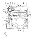
- FIG. FIG. 2 is a rear view showing a corner of the first unit in the electronic device of FIG. 1; Sectional drawing along the III-III line of FIG. Sectional drawing along the IV-IV line of FIG.
- the direction of hot air exhausted from the inside of the housing to the outside is determined by the inclination angle of the fins with respect to the normal to the side surface of the housing of the heat dissipation device.
- the air sent from the fan collides with the fins, it may be difficult to increase the amount of air blown from the fan.
- the present inventors devised an electronic device that guides the air sent from the blower along the blowing direction that intersects the exhaust surface, and improves the amount of air sent from the blower to the outside of the housing, The following inventions have been made.
- the electronic device of the first aspect of the present disclosure includes a housing having an exhaust surface provided with an exhaust port; an air blower disposed inside the housing for sending air from the inside of the housing to the outside of the housing through the exhaust port; an exhaust section provided inside the housing and having an exhaust path that guides air sent from the blower toward the exhaust port along a blowing direction that intersects the exhaust surface; A plurality of plate members arranged in the exhaust path and having plate surfaces that intersect in the thickness direction face each other, and each plate surface of the plurality of plate members extends along the blowing direction. and fins arranged in a vertical direction.
- the fins are provided in the exhaust path and have a plurality of plate members arranged such that the plate surfaces that intersect in the thickness direction face each other, and the plurality of plate members are arranged along the blowing direction.
- the electronic device of the second aspect of the present disclosure includes a heat pipe extending along the direction in which the plurality of plate members are arranged; the heat pipe a pipe body to which the fins are connected; a tip portion provided at one end of the pipe body in the arrangement direction of the plurality of plate members and arranged in a first region adjacent to the fins in the arrangement direction.
- the tip of the heat pipe that does not function as a heat transport element.
- the fins are connected to the pipe main body instead of the tip portion, the heat transported by the heat pipe can be efficiently transferred to the fins.
- the tip portion is arranged in the first region adjacent to the fin in the arrangement direction of the plurality of plate members. With such a configuration, it is possible to save the space inside the electronic device while maintaining the heat dissipation effect of the electronic device.
- An electronic device includes: A structure disposed inside the housing, The structure is arranged in a second region adjacent to the fins in the arrangement direction.
- the structure is arranged in the second region adjacent to the fins in the arrangement direction of the plurality of plate members.
- An electronic device includes The housing is configured by the exhaust surface and an intersecting surface that intersects the exhaust surface, and has a corner portion where the blower device and the exhaust unit are arranged,
- the structure is a protective member that protects the corner,
- the blower, the exhaust unit and the fins are arranged at the corners, the exhaust path extends in the direction in which the exhaust surface extends and in the direction away from the intersection surface as it approaches the exhaust surface along the direction in which the intersection surface extends;
- the second region is surrounded by the exhaust surface, the intersection surface and the fins.
- the protection member is arranged in the second region adjacent to the fins in the arrangement direction of the plurality of plate members and surrounded by the exhaust surface, the intersection surface and the fins.
- the electronic device 1 of the present embodiment is a notebook personal computer (in other words, a laptop PC) as shown in FIG.
- the electronic device 1 has a first unit 10 and a second unit 20 .
- the first unit 10 is detachably attached to the second unit 20 . That is, the electronic device 1 is configured as a so-called detachable computer.
- the first unit 10 is a tablet computer having a display section 11.
- the display unit 11 is configured by, for example, a liquid crystal display panel and a touch panel capable of accepting a user's touch operation.
- the first unit 10 incorporates a central processing unit (CPU), a volatile memory device (RAM), a nonvolatile memory device (ROM, SSD, etc.), a battery, and the like.
- An operating system (OS), various application programs, various data, and the like are stored in nonvolatile storage devices (ROM, SSD, etc.).
- a central processing unit (CPU) implements various functions by reading an OS, application programs, and various data and executing arithmetic processing.
- the second unit 20 is a station to which the first unit 10 is detachably attached.
- the second unit 20 includes input sections 21 and 22 , a socket 30 and a hinge 40 .
- the input units 21 and 22 are composed of, for example, keyboards and touch pads, and are configured so that users can perform input processing.
- the socket 30 removably accommodates the first unit 10 . It is arranged at one end of the second unit 20 in the depth direction (for example, Y direction) and connected to the second unit 20 via a hinge 40 .
- the hinge 40 has a rotation axis extending along the width direction (for example, the X direction) of the electronic device 1, rotates the socket 30 around this rotation axis, and rotates the socket 30 at an arbitrary angle with respect to the second unit 20. can hold.
- the first unit 10 can be positioned at an angle of 90 degrees with respect to the second unit 20. It will be in an open state.
- the closed state can be achieved.
- a "closed state” is a state in which the first unit 10 and the second unit 20 face each other closely and are substantially parallel to each other.
- FIGS. 2 to 4 some of the parts that make up the first unit 10 are omitted.
- the first unit 10 includes a housing 50 having an exhaust surface 51, a blower 60 arranged inside the housing 50, and an exhaust path 71 arranged inside the housing 50.
- An exhaust section 70 and fins 80 arranged in an exhaust path 71 are provided.
- the first unit 10 further comprises a heat pipe 90 and a structure 100. As shown in FIG.
- the housing 50 has a substantially rectangular plate shape and is configured to accommodate electronic components inside.
- the exhaust surface 51 forms one side surface of the housing 50 extending in the thickness direction (eg, Y direction). In this embodiment, the exhaust surface 51 extends in the width direction of the first unit 10, as shown in FIG.
- the exhaust surface 51 is provided with an exhaust port 52 for discharging the air sent from the blower 60 to the outside of the housing 50 .
- the housing 50 has a corner portion 54 formed by an exhaust surface 51 and an intersecting surface 53 that intersects the exhaust surface 51 .
- the cross plane 53 extends along the height direction (eg, Z direction) of the housing 50 .
- the blower 60 , the exhaust section 70 and the fins 80 are arranged at the corner 54 of the housing 50 .
- the air blower 60 is composed of, for example, a sirocco fan, and sends air from the inside of the housing 50 to the outside of the housing 50 through the exhaust port 52 .
- the blower device 60 is arranged inside the exhaust section 70 as shown in FIG. 2 .
- the blower device 60 is not limited to a sirocco fan, and can be configured by, for example, a fan other than an axial fan.
- the exhaust unit 70 guides the air sent from the blower 60 toward the exhaust port 52 along a blowing direction that intersects the exhaust surface 51 (for example, the direction of arrow A in FIG. 2). It has an exhaust path 71 .
- the angle ⁇ may be within the range of 65 degrees to 75 degrees.
- the exhaust section 70 has a box shape composed of curved portions 72 and linear portions 73, and an exhaust path 71 is formed therein.
- the exhaust path 71 extends in the direction in which the exhaust surface 51 extends and in the direction away from the intersection surface 53 as it approaches the exhaust surface 51 along the direction in which the intersection surface 53 extends.
- the curved portion 72 has an opening 74 facing the exhaust surface 51, and the blower device 60 is arranged inside the curved portion 72.
- the curved portion 72 has an intake port 75 provided on one surface of the housing 50 in the thickness direction. Air is supplied to the blower device 60 via the intake port 75 .
- the linear portion 73 extends from the opening 74 of the curved portion 72 along the blowing direction. Inside the linear portion 73, as shown in FIG. 3, a heat pipe 90 and a fin 80 connected to the heat pipe 90 are arranged.
- the linear portion 73 has a projecting portion 76 that is provided at the end closer to the curved portion 72 in the air blowing direction inside thereof and that positions the heat pipe 90 .
- the protrusion 76 is provided on the inner surface of the linear portion 73 facing the intake port 75 of the curved portion 72 in the thickness direction of the housing 50 and at the end closer to the intersecting surface 53 in the width direction of the housing 50. It is
- the projecting portion 76 is provided with two inclined surfaces 761 and 762 .
- the inclined surface 761 is inclined in the direction of approaching the intake port 75 in the thickness direction of the housing 50 as it approaches the mounting surface in the height direction of the housing 50 .
- the inclined surface 762 is inclined in the direction of approaching the intake port 75 in the thickness direction of the housing 50 as it approaches the intersecting surface 53 in the width direction of the housing 50 .
- the fin 80 has a plurality of plate members 81.
- the plurality of plate members 81 are arranged at intervals in the width direction of the housing 50 so that the plate surfaces that intersect in the thickness direction of the plate members 81 face each other.
- the plate surface of each plate member 81 is arranged along the blowing direction (in other words, substantially parallel to the blowing direction).
- the heat pipe 90 extends along the width direction of the housing 50 (in other words, the arrangement direction D1 of the plurality of plate members 81).
- the heat pipe 90 has a pipe body 91 and a tip portion 92 provided at one end of the pipe body 91 in the width direction of the housing 50 .
- the pipe body 91 has a plate shape with a rectangular cross section, and the fins 80 are connected to one surface in the thickness direction.
- the exhaust path 71 inside the linear portion 73 is substantially entirely covered with the fins 80 and the pipe body 91 .
- a first region 77 in which the tip portion 92 is arranged is provided at the end of the linear portion 73 in the width direction of the housing 50 and closer to the intersecting surface 53 .
- the first region 77 is arranged adjacent to the intersecting surface 53 closer to the fins 80 in the width direction of the housing 50 and is surrounded by the linear portion 73 and the fins 80 .
- the first region 77 is a region that does not overlap the fins 80 when viewed along the thickness direction (eg, Y direction) of the housing 50 .
- the structure 100 is, for example, a protection member that protects the corners 54 of the housing 50 .
- the protective member 100 is arranged in a second region 55 that is adjacent in the arrangement direction of the plurality of plate members 81 and surrounded by the exhaust surface 51 , the intersection surface 53 and the fins 80 .
- the electronic device 1 can exhibit the following effects.
- the fin 80 is provided in the exhaust path 71 and has the plurality of plate members 81 arranged so that the plate surfaces crossing in the thickness direction face each other. Each plate surface of 81 is arranged along the blowing direction. With such a configuration, it is possible to suppress a decrease in the air volume due to the air sent from the air blower 60 passing through the fins 80 . As a result, the electronic device 1 is realized in which the amount of air sent from the blower 60 to the outside of the housing 50 is increased while guiding the air sent from the blower 60 along the blowing direction intersecting the exhaust surface 51. can.
- the tip of the heat pipe 90 has a region that does not function as a heat transport element.
- the fins 80 are connected to the pipe main body 91 instead of the tip portion 92 of the heat pipe 90, so that the heat transported by the heat pipe 90 can be efficiently transferred to the fins 80.
- the tip portion 92 is arranged in the first region 77 adjacent to the fin 80 in the arrangement direction of the plurality of plate members 81 .
- the heat pipes 90 are arranged in the first region 77, which is the space formed between the linear portions 73 of the exhaust section 70 and the fins 80.
- a tip 92 is arranged. With such a configuration, it is possible to save the space inside the electronic device 1 while maintaining the heat radiation effect of the electronic device 1 .
- the structure 100 is arranged in the second region 55 adjacent to the fins 80 in the arrangement direction of the plurality of plate members 81 . With such a configuration, it is possible to save the space inside the electronic device 1 while maintaining the heat radiation effect of the electronic device 1 .
- a protective member 100 is arranged in a second region 55 adjacent to the fins 80 in the arrangement direction of the plurality of plate members 81 and surrounded by the exhaust surface 51 , the intersecting surface 53 and the fins 80 .
- the protective member 100 is arranged in a space surrounded by the exhaust surface 51 , the intersecting surface 53 and the fins 80 formed by arranging the plate members 81 of the fins 80 along the blowing direction.
- the electronic device 1 can also be configured as follows.
- the electronic device 1 does not have to include the heat pipe 90 and the structure 100.
- the air blower 60 , the exhaust section 70 and the fins 80 may be arranged at positions away from the corners 54 of the housing 50 .
- the structure 100 is not limited to a protective member, and may be a camera, for example.
- the blower 60, the exhaust section 70, and the fins 80 can be arranged not only at the corner 54, but also at or near the corner of any housing 50.
- the exhaust part 70 is not limited to being composed of the curved part 72 and the linear part 73, and any configuration in which the exhaust path 71 can be formed inside can be adopted.
- the exhaust path 71 is not limited to extending in the direction in which the exhaust surface 51 extends and in the direction away from the intersecting surface 53 as it approaches the exhaust surface 51 along the direction in which the intersecting surface 53 extends.
- the exhaust path 71 can also be configured to extend in the direction in which the exhaust surface 51 extends and in the direction to approach the intersection surface 53 as it approaches the exhaust surface 51 along the direction in which the intersection surface 53 extends.
- the fins 80 have a plurality of plate members 81, and any configuration that can be arranged in the exhaust path 71 can be adopted.
- the present disclosure can also be applied to an electronic device in which the blower 60, the exhaust section 70 and the fins 80 are arranged inside the housing of the second unit 20.
- the present disclosure can be widely applied to electronic devices including notebook personal computers.
Abstract
Description
排気口を含む排気面を有する筐体と、
前記筐体の内部に配置され、前記筐体の内部から前記排気口を介して前記筐体の外部に空気を送る送風装置と、
前記筐体の内部に配置され、前記送風装置から送られた空気を前記排気面に交差する送風方向に沿って前記排気口に向かって案内する排気経路を有する排気部と、
前記排気経路に配置され、複数の板部材を有するフィンとを備える。前記複数の板部材の各々は、前記送風方向に沿って配置されている。 An electronic device according to one aspect of the present disclosure includes:
a housing having an exhaust surface including an exhaust port;
an air blower disposed inside the housing for sending air from the inside of the housing to the outside of the housing through the exhaust port;
an exhaust unit disposed inside the housing and having an exhaust path that guides air sent from the blower toward the exhaust port along a blowing direction that intersects the exhaust surface;
and a fin having a plurality of plate members arranged in the exhaust path. Each of the plurality of plate members is arranged along the blowing direction.
特許文献1の携帯情報機器では、放熱装置の筐体の側面の法線に対するフィンの傾斜角度によって、筐体の内部から外部に排気される熱風の排気方向が決められている。つまり、特許文献1の携帯情報機器では、ファンから送られた空気がフィンに衝突するため、ファンからの送風量を向上させることが難しい場合がある。 (Circumstances leading to this disclosure)
In the portable information device of
排気口が設けられた排気面を有する筐体と、
前記筐体の内部に配置され、前記筐体の内部から前記排気口を介して前記筐体の外部に空気を送る送風装置と、
前記筐体の内部に設けられ、前記送風装置から送られた空気を前記排気面に交差する送風方向に沿って前記排気口に向かって案内する排気経路を有する排気部と、
前記排気経路に配置され、厚さ方向に交差する板面同士が相互に対向するように配置された複数の板部材を有し、前記複数の板部材の各々の板面が前記送風方向に沿って配置されているフィンとを備える。 The electronic device of the first aspect of the present disclosure includes
a housing having an exhaust surface provided with an exhaust port;
an air blower disposed inside the housing for sending air from the inside of the housing to the outside of the housing through the exhaust port;
an exhaust section provided inside the housing and having an exhaust path that guides air sent from the blower toward the exhaust port along a blowing direction that intersects the exhaust surface;
A plurality of plate members arranged in the exhaust path and having plate surfaces that intersect in the thickness direction face each other, and each plate surface of the plurality of plate members extends along the blowing direction. and fins arranged in a vertical direction.
前記複数の板部材の配列方向に沿って延びるヒートパイプを備え、
前記ヒートパイプが、
前記フィンが接続されたパイプ本体と、
前記パイプ本体の前記複数の板部材の配列方向の一端に設けられ、前記配列方向において前記フィンに隣接する第1領域に配置されている先端部とを有する。 The electronic device of the second aspect of the present disclosure includes
a heat pipe extending along the direction in which the plurality of plate members are arranged;
the heat pipe
a pipe body to which the fins are connected;
a tip portion provided at one end of the pipe body in the arrangement direction of the plurality of plate members and arranged in a first region adjacent to the fins in the arrangement direction.
前記筐体の内部に配置された構造物を備え、
前記構造物が、前記配列方向において前記フィンに隣接する第2領域に配置されている。 An electronic device according to a third aspect of the present disclosure includes:
A structure disposed inside the housing,
The structure is arranged in a second region adjacent to the fins in the arrangement direction.
前記筐体が、前記排気面と前記排気面に交差する交差面とで構成され、前記送風装置および前記排気部が配置された角部を有し、
前記構造物が前記角部を保護する保護部材であり、
前記送風装置、前記排気部および前記フィンが前記角部に配置され、
前記排気経路が、前記交差面が延びる方向に沿って前記排気面に接近するに従って、前記排気面が延びる方向でかつ前記交差面から離れる方向に延びており、
前記第2領域が、前記排気面、前記交差面および前記フィンで囲まれている。 An electronic device according to a fourth aspect of the present disclosure includes
The housing is configured by the exhaust surface and an intersecting surface that intersects the exhaust surface, and has a corner portion where the blower device and the exhaust unit are arranged,
The structure is a protective member that protects the corner,
The blower, the exhaust unit and the fins are arranged at the corners,
the exhaust path extends in the direction in which the exhaust surface extends and in the direction away from the intersection surface as it approaches the exhaust surface along the direction in which the intersection surface extends;
The second region is surrounded by the exhaust surface, the intersection surface and the fins.
本実施形態の電子機器1は、一例として、図1に示すように、ノートブック型のパーソナルコンピュータ(言い換えると、ラップトップPC)である。電子機器1は、第1ユニット10と、第2ユニット20とを備える。第1ユニット10は、第2ユニット20に対して取り外し可能に取り付けられている。つまり、電子機器1は、いわゆるデタッチャブル型コンピュータとして構成されている。 (embodiment)
As an example, the
10 第1ユニット
11 表示部
20 第2ユニット
21、22 入力部
30 ソケット
40 ヒンジ
50 筐体
51 排気面
52 排気口
53 交差面
54 角部
55 第2領域
60 送風装置
70 排気部
71 排気経路
72 湾曲部
73 線状部
74 開口部
75 吸気口
76 突起部
761、762 傾斜面
77 第1領域
80 フィン
81 板部材
90 ヒートパイプ
91 パイプ本体
92 先端部
100 保護部材 1
Claims (7)
- 排気口を含む排気面を有する筐体と、
前記筐体の内部に配置され、前記筐体の内部から前記排気口を介して前記筐体の外部に空気を送る送風装置と、
前記筐体の内部に配置され、前記送風装置から送られた空気を前記排気面に交差する送風方向に沿って前記排気口に向かって案内する排気経路を有する排気部と、
前記排気経路に配置され、複数の板部材を有するフィンとを備え、
前記複数の板部材の各々は、前記送風方向に沿って配置されている、電子機器。 a housing having an exhaust surface including an exhaust port;
an air blower disposed inside the housing for sending air from the inside of the housing to the outside of the housing through the exhaust port;
an exhaust unit disposed inside the housing and having an exhaust path that guides air sent from the blower toward the exhaust port along a blowing direction that intersects the exhaust surface;
a fin disposed in the exhaust path and having a plurality of plate members,
The electronic device, wherein each of the plurality of plate members is arranged along the blowing direction. - 前記複数の板部材の配列方向に沿って延びるヒートパイプをさらに備え、
前記ヒートパイプが、
前記フィンと接続されたパイプ本体と、
前記配列方向において前記パイプ本体の一端に設けられ、前記配列方向において前記フィンに隣接する第1領域に配置されている先端部とを有する、請求項1の電子機器。 further comprising a heat pipe extending along the direction in which the plurality of plate members are arranged;
the heat pipe
a pipe body connected to the fins;
2. The electronic device according to claim 1, further comprising a tip provided at one end of said pipe body in said arrangement direction and arranged in a first region adjacent to said fin in said arrangement direction. - 前記第1領域は、前記筐体の厚さ方向に沿って見たときに、前記フィンと重ならない領域である、請求項2の電子機器。 The electronic device according to claim 2, wherein the first region is a region that does not overlap the fins when viewed along the thickness direction of the housing.
- 前記筐体の内部に配置された構造物をさらに備え、
前記構造物が、前記複数の板部材の配列方向において前記フィンに隣接する第2領域に配置されている、請求項1から3のいずれかの電子機器。 Further comprising a structure arranged inside the housing,
4. The electronic device according to any one of claims 1 to 3, wherein said structure is arranged in a second region adjacent to said fin in the arrangement direction of said plurality of plate members. - 前記筐体が、前記排気面と前記排気面に交差する交差面とで構成された角部を有し、
前記構造物が、前記角部を保護する保護部材であり、
前記送風装置、前記排気部および前記フィンが、前記角部に配置され、
前記排気経路が、前記交差面が延びる方向に沿って前記排気面に接近するに従って、前記交差面から離れる方向に延びており、
前記第2領域が、前記排気面、前記交差面および前記フィンで囲まれている、請求項4の電子機器。 the housing has a corner formed by the exhaust surface and an intersecting surface that intersects the exhaust surface;
The structure is a protective member that protects the corner,
The blower, the exhaust unit and the fins are arranged at the corners,
the exhaust path extends away from the intersecting surface as it approaches the exhaust surface along the direction in which the intersecting surface extends;
5. The electronic device of claim 4, wherein the second region is bounded by the exhaust surface, the intersection surface and the fins. - 前記筐体の内部に配置された構造物をさらに備え、
前記構造物が、前記複数の板部材の配列方向において前記フィンに隣接する第2領域に配置されており、
前記構造物が、前記角部を保護する保護部材であり、
前記送風装置、前記排気部および前記フィンが、前記角部に配置され、
前記排気経路が、前記交差面が延びる方向に沿って前記排気面に接近するに従って、前記交差面から離れる方向に延びており、
前記第2領域が、前記排気面、前記交差面および前記フィンで囲まれており、
前記第1領域が、前記前記第2領域と前記フィンとの間に位置する、請求項3の電子機器。 Further comprising a structure arranged inside the housing,
The structure is arranged in a second region adjacent to the fin in the arrangement direction of the plurality of plate members,
The structure is a protective member that protects the corner,
The blower, the exhaust unit and the fins are arranged at the corners,
the exhaust path extends away from the intersecting surface as it approaches the exhaust surface along the direction in which the intersecting surface extends;
the second region is surrounded by the exhaust surface, the intersection surface and the fins;
4. The electronic device of claim 3, wherein the first region is located between the second region and the fin. - 前記送風方向と前記排気面との成す角度は、65度から75度の範囲内である、請求項1から6のいずれかの電子機器。 The electronic device according to any one of claims 1 to 6, wherein the angle formed by the blowing direction and the exhaust surface is within the range of 65 degrees to 75 degrees.
Priority Applications (4)
| Application Number | Priority Date | Filing Date | Title |
|---|---|---|---|
| JP2023502072A JPWO2022180957A1 (en) | 2021-02-26 | 2021-11-19 | |
| EP21928051.8A EP4300568A1 (en) | 2021-02-26 | 2021-11-19 | Electronic device |
| CN202180094503.8A CN116982016A (en) | 2021-02-26 | 2021-11-19 | Electronic equipment |
| US18/235,830 US20230393636A1 (en) | 2021-02-26 | 2023-08-19 | Electronic device |
Applications Claiming Priority (2)
| Application Number | Priority Date | Filing Date | Title |
|---|---|---|---|
| JP2021029445 | 2021-02-26 | ||
| JP2021-029445 | 2021-02-26 |
Related Child Applications (1)
| Application Number | Title | Priority Date | Filing Date |
|---|---|---|---|
| US18/235,830 Continuation US20230393636A1 (en) | 2021-02-26 | 2023-08-19 | Electronic device |
Publications (1)
| Publication Number | Publication Date |
|---|---|
| WO2022180957A1 true WO2022180957A1 (en) | 2022-09-01 |
Family
ID=83047905
Family Applications (1)
| Application Number | Title | Priority Date | Filing Date |
|---|---|---|---|
| PCT/JP2021/042681 WO2022180957A1 (en) | 2021-02-26 | 2021-11-19 | Electronic device |
Country Status (5)
| Country | Link |
|---|---|
| US (1) | US20230393636A1 (en) |
| EP (1) | EP4300568A1 (en) |
| JP (1) | JPWO2022180957A1 (en) |
| CN (1) | CN116982016A (en) |
| WO (1) | WO2022180957A1 (en) |
Citations (4)
| Publication number | Priority date | Publication date | Assignee | Title |
|---|---|---|---|---|
| JP2010026522A (en) * | 2009-10-08 | 2010-02-04 | Casio Comput Co Ltd | Projector |
| JP2012191504A (en) * | 2011-03-11 | 2012-10-04 | Toshiba Corp | Television receiver and electronic apparatus |
| JP2014085973A (en) | 2012-10-25 | 2014-05-12 | Nec Personal Computers Ltd | Heat dissipation device and portable information equipment |
| JP2017055271A (en) * | 2015-09-09 | 2017-03-16 | 富士通株式会社 | Information processor |
-
2021
- 2021-11-19 EP EP21928051.8A patent/EP4300568A1/en active Pending
- 2021-11-19 CN CN202180094503.8A patent/CN116982016A/en active Pending
- 2021-11-19 JP JP2023502072A patent/JPWO2022180957A1/ja active Pending
- 2021-11-19 WO PCT/JP2021/042681 patent/WO2022180957A1/en active Application Filing
-
2023
- 2023-08-19 US US18/235,830 patent/US20230393636A1/en active Pending
Patent Citations (4)
| Publication number | Priority date | Publication date | Assignee | Title |
|---|---|---|---|---|
| JP2010026522A (en) * | 2009-10-08 | 2010-02-04 | Casio Comput Co Ltd | Projector |
| JP2012191504A (en) * | 2011-03-11 | 2012-10-04 | Toshiba Corp | Television receiver and electronic apparatus |
| JP2014085973A (en) | 2012-10-25 | 2014-05-12 | Nec Personal Computers Ltd | Heat dissipation device and portable information equipment |
| JP2017055271A (en) * | 2015-09-09 | 2017-03-16 | 富士通株式会社 | Information processor |
Also Published As
| Publication number | Publication date |
|---|---|
| EP4300568A1 (en) | 2024-01-03 |
| JPWO2022180957A1 (en) | 2022-09-01 |
| US20230393636A1 (en) | 2023-12-07 |
| CN116982016A (en) | 2023-10-31 |
Similar Documents
| Publication | Publication Date | Title |
|---|---|---|
| US8717762B2 (en) | Electronic apparatus and cooling fan | |
| TWI645281B (en) | Electronic equipment | |
| JP2005107122A (en) | Electronic equipment | |
| US8164900B2 (en) | Enclosure of electronic device | |
| US20100214738A1 (en) | Portable electronic device and dissipating structure thereof | |
| US20090154087A1 (en) | Display apparatus and electronic apparatus | |
| WO2022180957A1 (en) | Electronic device | |
| TWM562995U (en) | Portable electronic apparatus | |
| US20130223007A1 (en) | Television and electronic apparatus | |
| EP2706430A2 (en) | Portable computer having heat dissipation structure | |
| TW201320882A (en) | Fan duct and electronic device using the same | |
| JP2014085973A (en) | Heat dissipation device and portable information equipment | |
| TWI344814B (en) | Case of electronic device | |
| JP2006222254A (en) | Electronic apparatus | |
| JP2011003204A (en) | Electronic equipment | |
| US20060049728A1 (en) | Computer bezel with inlet airflow guiding device | |
| WO2022181147A1 (en) | Electronic device | |
| JP4171028B2 (en) | Electronics | |
| JP5733144B2 (en) | Electronics | |
| TWI466626B (en) | Electronic device and case used in the same | |
| JP6967728B2 (en) | Electronics | |
| US20200362880A1 (en) | Centrifugal fan and electronic device | |
| US20090154081A1 (en) | Electronic apparatus | |
| JP2020183721A (en) | Centrifugal fan and electronic device | |
| TW201407314A (en) | Electronic device and heat dissipation module |
Legal Events
| Date | Code | Title | Description |
|---|---|---|---|
| 121 | Ep: the epo has been informed by wipo that ep was designated in this application |
Ref document number: 21928051 Country of ref document: EP Kind code of ref document: A1 |
|
| WWE | Wipo information: entry into national phase |
Ref document number: 2023502072 Country of ref document: JP |
|
| WWE | Wipo information: entry into national phase |
Ref document number: 202180094503.8 Country of ref document: CN |
|
| WWE | Wipo information: entry into national phase |
Ref document number: 2021928051 Country of ref document: EP |
|
| NENP | Non-entry into the national phase |
Ref country code: DE |
|
| ENP | Entry into the national phase |
Ref document number: 2021928051 Country of ref document: EP Effective date: 20230926 |