WO2022180763A1 - Heat detector - Google Patents
Heat detector Download PDFInfo
- Publication number
- WO2022180763A1 WO2022180763A1 PCT/JP2021/007244 JP2021007244W WO2022180763A1 WO 2022180763 A1 WO2022180763 A1 WO 2022180763A1 JP 2021007244 W JP2021007244 W JP 2021007244W WO 2022180763 A1 WO2022180763 A1 WO 2022180763A1
- Authority
- WO
- WIPO (PCT)
- Prior art keywords
- visible
- heat sensor
- guard structure
- sensing
- light
- Prior art date
Links
- 239000000758 substrate Substances 0.000 claims description 37
- 239000000853 adhesive Substances 0.000 claims description 25
- 230000001070 adhesive effect Effects 0.000 claims description 25
- 238000009792 diffusion process Methods 0.000 claims description 16
- 238000012544 monitoring process Methods 0.000 claims description 16
- 239000000463 material Substances 0.000 claims description 13
- 238000012856 packing Methods 0.000 claims description 12
- 230000002093 peripheral effect Effects 0.000 description 12
- 239000000428 dust Substances 0.000 description 2
- 238000000034 method Methods 0.000 description 2
- XLYOFNOQVPJJNP-UHFFFAOYSA-N water Substances O XLYOFNOQVPJJNP-UHFFFAOYSA-N 0.000 description 2
- 230000005856 abnormality Effects 0.000 description 1
- 238000007792 addition Methods 0.000 description 1
- 238000004891 communication Methods 0.000 description 1
- 239000000470 constituent Substances 0.000 description 1
- 238000001514 detection method Methods 0.000 description 1
- 238000002347 injection Methods 0.000 description 1
- 239000007924 injection Substances 0.000 description 1
- 238000009434 installation Methods 0.000 description 1
- 238000004519 manufacturing process Methods 0.000 description 1
- 230000035945 sensitivity Effects 0.000 description 1
- 238000006467 substitution reaction Methods 0.000 description 1
- 238000012360 testing method Methods 0.000 description 1
Images


Classifications
-
- G—PHYSICS
- G08—SIGNALLING
- G08B—SIGNALLING OR CALLING SYSTEMS; ORDER TELEGRAPHS; ALARM SYSTEMS
- G08B17/00—Fire alarms; Alarms responsive to explosion
- G08B17/06—Electric actuation of the alarm, e.g. using a thermally-operated switch
Definitions
- the present invention relates to heat sensors.
- the heat sensor is equipped with an indicator light to let you know that it is working.
- indicator lamps are provided outside a guard structure (thermistor guard) that protects a sensing portion that senses heat in plan view.
- the sensing part and the LED, which is the light source of the indicator light, are both electrically connected to a built-in mounting board. Planar view indicates a state viewed from above and below.
- the indicator lamp is arranged outside the guard structure in plan view, so the LED and the sensing portion are electrically connected to the mounting board at positions separated from each other. be.
- the LED and the sensing portion are electrically connected to the mounting board at positions separated from each other.
- the present invention provides a heat sensor capable of reducing the size of the mounting substrate and reducing restrictions on the arrangement of the light source device of the indicator lamp.
- a heat sensor includes a sensing portion exposed to a monitoring area to sense heat; and an indicator light for indicating the heat sensor, wherein at least a part of the indicator light is inside the guard structure in plan view and around the sensing part It has a planar visible part, and at least part of the visible part is visible through the guard structure from the monitoring area side.
- the visible portion is arranged inside the guard structure and around the sensing portion in plan view.
- the light source device for the visible part is arranged at a position close to the sensing part.
- the visible part is arranged in a plane around the sensing part, and at least part of the visible part is visible through the guard structure from the monitoring area side. This makes it easier for the user to visually recognize the visible portion.
- a heat sensor includes a sensing portion exposed to a monitoring area to sense heat, and a guard structure provided around the sensing portion to protect the sensing portion from external force on the monitoring area side. , and an indicator lamp for indicating a heat sensor, wherein the indicator lamp is arranged in an area protected by the guard structure, and at least a part thereof is exposed without overlapping the guard structure in a plan view. It has a planar visible part.
- the visible portion is located within the area protected by the guard structure.
- the light source device for the visible part is arranged at a position close to the sensing part.
- at least a part of the visible part has a planar shape that is exposed without overlapping the guard structure in a plan view. This makes it easier for the user to visually recognize the visible portion.
- the heat sensor further includes a mounting board to which the sensing section is electrically connected, and the indicator lamp is electrically connected to the mounting board.
- a light source device may be provided, and the visible portion may display light projected from the light source device.
- the visible part and the sensing part are arranged at positions close to each other, the position at which the heat sensor is electrically connected on the mounting substrate and the position at which the light source device is electrically connected are close to each other. can be placed in position. As a result, it is possible to reduce the size of the mounting substrate and reduce the restrictions on the arrangement of the light source device.
- the visible portion is configured by a portion of a plate-like member provided with a transparent or translucent light diffusion portion, and the light diffusion portion is the mounting substrate in a plan view. may be placed overlapping each other.
- the visible portion is configured by a portion of the plate-like member provided with the transparent or translucent light diffusing portion.
- the light diffusing section can diffuse the light from the light source device. Therefore, the visible portion can reliably display the heat sensor.
- the light diffusing section is arranged so as to overlap with the mounting substrate in a plan view. Thereby, the distance between the light source device electrically connected to the mounting board and the light diffusion section can be shortened. Therefore, the light from the light source device can be reliably projected onto the light diffusing portion.
- the light diffusion section may be arranged so as to surround the sensing section.
- the user can easily visually recognize the visible part.
- the heat sensor according to one aspect of the present embodiment has a cover portion provided between the mounting board and the guard structure, and the cover portion has an opening that exposes the visible portion. good.
- the opening for exposing the visible portion is formed in the cover portion.
- the visible part can be provided around the sensing part so that at least a part thereof is arranged inside the guard structure in plan view.
- each of the side of the guard structure facing the visible portion and the cover portion has a color capable of reflecting visible light emitted from the indicator lamp.
- the guard structure can reflect visible light emitted from the indicator lamp.
- the heat sensor can display the heat sensor by using not only the visible light emitted from the indicator lamp but also the reflected light reflected by the guard structure and the cover portion.
- a waterproof material may be provided between the sensing portion and the visible portion.
- the waterproofness of the sensing unit can be enhanced.
- the waterproof material may be an adhesive
- the visible portion can be adhered to the mounting board or other members around the sensing portion.
- the heat sensor further includes a mounting substrate to which the sensing portion is electrically connected, and a cover provided between the mounting substrate and the guard structure.
- an opening exposing the visible portion is formed in the cover portion; a groove portion into which the adhesive can be injected is formed in the visible portion; It may reach between the portion and the cover portion.
- the gap between the sensing section and the visible section can be filled with the adhesive by injecting the adhesive into the groove. Also, the adhesive injected into the groove portion and reaching the cover portion can adhere the visible portion and the cover portion.
- packing may be provided between the visible portion and the mounting board.
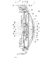
- FIG. 1 is a plan view of a heat sensor according to a first embodiment
- FIG. FIG. 2 is a cross-sectional view of the heat sensor according to the first embodiment taken along line AA
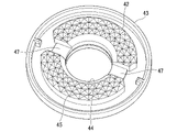
- FIG. 4 is a perspective view of the heat sensor with the guard structure omitted; It is a perspective view of a plate-shaped member.
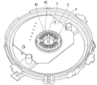
- FIG. 4 is a perspective view showing the heat sensor before the plate member is installed on the mounting substrate;
- FIG. 4 is a perspective view showing a plate-like member to which packing is attached;
- FIG. 4 is a perspective view showing the heat sensor after the plate-shaped member is installed on the mounting substrate;
- FIG. 4 is a perspective view showing the heat sensor after installing the inner cover part;
- FIG. 4 is a perspective view showing a state in which an adhesive is injected;
- the heat sensor 1 according to the embodiment of the invention shown in FIGS. 1 and 2 is attached to the ceiling surface 11 .
- the heat sensor 1 shown in FIG. 1 shows the lower surface when attached to the ceiling surface 11 .
- the heat sensor 1 has a circular shape when viewed from the top and bottom.
- the heat sensor 1 has a sensing portion 2 , a mounting substrate 3 , an indicator light 4 , an outer cover portion 5 , an inner cover portion 6 (cover portion), and a guard structure 7 .
- the sensing unit 2 is exposed to the monitoring area 12 and senses heat.
- the monitoring area 12 is an area below the ceiling surface 11 and below and around the heat sensor 1 .
- the outer cover portion 5 is provided on the outer peripheral portion of the heat sensor 1 in plan view.
- the heat sensor 1 is shown upside down and the guard structure 7 is omitted.
- the outer cover portion 5 has a cylindrical portion 51 and an annular portion 52 .
- the cylindrical portion 51 is a cylindrical member.
- the cylindrical portion 51 is provided on the outer circumference of the heat sensor 1 in plan view so as to open in the vertical direction.
- An upper end portion 511 (see FIG. 2) of the cylindrical portion 51 is in contact with the ceiling surface 11 .
- the annular portion 52 is an annular member having a circular annular portion opening 53 inside.
- the annular portion 52 is oriented to open in the vertical direction, and the outer peripheral edge 521 (see FIG. 2) is connected to the lower end portion 512 (see FIG. 2) of the cylindrical portion 51 .
- the cylindrical portion 51 and the annular portion 52 are integrally formed.
- the inner cover part 6 is fitted into the annular opening 53 of the annular part 52 .
- the inner cover portion 6 is an annular member having a circular inner cover portion opening 61 inside.
- the inner cover portion 6 is oriented to open in the vertical direction, and the outer peripheral portion thereof is fixed to the inner peripheral portion of the annular portion 52 .
- the inner cover portion opening 61 is arranged in the central portion of the heat sensor 1 in plan view.
- the mounting board 3 is arranged inside the outer cover portion 5 and above the inner cover portion 6 .
- the mounting substrate 3 is arranged in the central portion of the heat sensor 1 in plan view.
- a part of the mounting board 3 is arranged above the inner cover opening 61 in the vertical direction, and a part thereof is arranged above the inner cover part 6 in the vertical direction.
- Components of the heat sensor 1 such as the control section are arranged inside the outer cover section 5 and on the upper side of the inner cover section 6 , and some of them are electrically connected to the mounting board 3 .
- the sensing unit 2 is a detection element that detects temperature by heat or hot airflow.
- the sensing part 2 is a rod-shaped member.
- the sensing unit 2 extends vertically and is arranged in the central portion of the heat sensor 1 in a plan view.
- the sensing portion 2 penetrates through the inner cover portion opening 61 .
- An upper side of the sensing section 2 is electrically connected to the mounting board 3 .
- a lower side of the sensing portion 2 protrudes below the inner cover portion 6 .
- the indicator light 4 indicates the operation of the sensing part 2.
- the indicator lamp 4 has a light source device 41 (see FIG. 2) and a visible portion 42 .
- the light source device 41 is an LED element, for example, and is electrically connected to the mounting board 3 .
- the indicator lamp 4 of this embodiment has two light source devices 41 .
- the light source devices 41 are arranged on both sides of the sensing section 2 in plan view.
- the visible portion 42 is configured by a portion of the plate-like member 43 .
- the plate-like member 43 is an annular plate-like member having a circular plate-like member opening 44 inside.
- the plate-like member 43 is oriented so that the surface that will be the lower side when installed on the ceiling surface is the upper side.
- the plate member 43 is arranged so as to open in the vertical direction.
- the plate-like member 43 is arranged so that the sensing portion 2 is inserted through the plate-like member opening 44 and surrounds the sensing portion 2 in plan view.
- the plate member 43 has a transparent or opaque light diffusing portion 45 .
- the light diffusion part 45 has a large number of reflecting surfaces that reflect light, and diffuses the light reflected by each of the large number of reflecting surfaces.
- the plate-like member 43 is arranged below the mounting board 3 in the vertical direction with an annular packing 46 interposed therebetween.
- the packing 46 is arranged between the inner portion of the plate member 43 and the mounting board 3 in plan view.
- the light source device 41 is electrically connected to the mounting board 3 on the vertically upper side of the light diffusion portion 45 of the plate member 43 . Light projected from the light source device 41 travels downward and passes through the light diffusing portion 45 of the plate member 43 . In this embodiment, the light source device 41 protrudes downward from the mounting board 3 .
- a concave portion 431 into which the light source device 41 projecting from the mounting board 3 is inserted is formed in the plate-like member 43 .
- the plate member By inserting the light source device 41 into the concave portion 431 of the plate member 43, the plate member can be easily positioned.
- the inner cover part 6 is arranged below the plate member 43 .
- the plate-like member 43 has an inner portion in plan view arranged inside the inner cover portion opening 61 , and an outer portion overlaps the inner cover portion 6 in plan view.
- a groove portion 47 extending in the radial direction is formed on the lower surface of the plate-like member 43 .
- the groove portion 47 has an inner end portion reaching the mounting substrate 3 around the sensing portion 2 in a plan view, and an outer end portion reaching the inner peripheral edge 62 of the inner cover portion 6 (the edge portion of the inner cover portion opening 61). reached.
- An adhesive 8 is filled in the lower side of the mounting substrate 3 around the sensing section 2 in the inner side 441 of the groove portion 47 of the plate-like member 43 and the plate-like member opening 44 shown in FIGS.
- the mounting substrate 3 , the plate-like member 43 and the inner cover portion 6 are adhered with the adhesive 8 .
- the adhesive 8 also has a waterproof property. The adhesive 8 seals the sensing portion 2 and the mounting substrate 3 around the sensing portion 2 to ensure waterproofness.
- the guard structure 7 is a member such as a thermistor guard, which is provided around the sensing section 2 and protects the sensing section 2 from external force on the monitoring area side.
- the guard structure 7 is arranged below the inner cover portion 6 and supported by the outer cover portion 5 .
- the guard structure 7 has an inner ring 71 , an outer ring 72 , inner ribs 73 and outer ribs 74 .
- the inner ring 71 is an annular member.
- the inner ring 71 is arranged below the sensing section 2 so as to open vertically. In plan view, the center of the inner ring 71 and the sensing portion 2 are arranged to overlap each other.
- the outer ring 72 is an annular member that is larger than the inner ring 71 .
- the outer ring 72 is arranged coaxially with the inner ring 71 so as to open vertically.
- the inner peripheral edge of the outer ring 72 and the outer peripheral edge of the inner ring 71 are spaced apart.
- the outer ring 72 is positioned above the inner ring 71 .
- the sensing part 2 is arranged inside the inner ring 71 .
- the inner rib 73 connects the inner ring 71 and the outer ring 72 .
- the inner rib 73 is a rod-shaped member.
- a plurality of inner ribs 73 are provided.
- the plurality of inner ribs 73 are radially extending from the inner ring 71 toward the outer ring 72 in plan view, and are spaced apart in the circumferential direction.
- Each of the inner ribs 73 has one end connected to the inner ring 71 and the other end connected to the outer ring 72 .
- the outer rib 74 is connected with the outer ring 72 and fixed to the outer cover portion 5 .
- the outer rib 74 is a rod-shaped member.
- a plurality of outer ribs 74 are provided.
- a plurality of outer ribs 74 extend radially outward from the outer ring 72 in plan view and are circumferentially spaced apart.
- Each of the plurality of outer ribs 74 has one end connected to the outer ring 72 and the other end fixed to the outer cover portion 5 .
- the annular portion 52 of the outer cover portion 5 is provided with a fixing portion 54 (see FIG. 1) for fixing the outer rib 74 to the edge portion of the annular portion opening 53 .
- the guard structure 7 is radially adjacent to the inner side of the inner ring 71 , between the radially adjacent inner ribs 73 between the inner ring 71 and the outer ring 72 , and between the outer rib 74 and the outer cover portion 5 .
- An opening is provided between the outer ribs 74 . This open portion is configured to allow air to pass through.
- the guard structure 7 is arranged inside the annular portion opening 53 of the outer cover portion 5 in plan view.
- the opening between the inner ribs 73 and the opening between the outer ribs 74 are designed to be large enough to prevent fingers from entering.
- Both the inner rib 73 and the outer rib 74 are arranged inside the inner peripheral edge of the outer cover portion 5 in plan view.
- the inner rib 73 is arranged inside the inner peripheral edge 62 of the inner cover portion 6 in plan view.
- the outer rib 74 is arranged outside the inner peripheral edge 62 of the inner cover portion 6 in plan view.
- a portion of the visible portion 42 (the plate-like member 43 ) that is arranged inside the inner cover portion opening 61 is arranged inside the outer ring 72 in plan view.
- the inner peripheral edge of the visible portion 42 substantially overlaps the inner ring 71 in plan view.
- the visible part 42 is arranged between the outer ring 72 and the inner ring 71 , and at least a portion of the visible part 42 is exposed to the monitoring area 12 without overlapping the guard structure 7 so that the user can see the guard structure 7 from the monitoring area 12 . Visible through.
- the light source device 41 is arranged at a portion of the visible portion 42 that is arranged inside the inner cover portion opening 61 , that is, at a position that does not vertically overlap the inner cover portion 6 . Therefore, the light source device 41 is also arranged inside the outer ring 72 in plan view.
- the mounting substrate 3, the sensing section 2, and the light source device 41 are manufactured by a known method, and are put into an assembled state as shown in FIG.
- the packing 46 is attached to the surface of the plate-like member 43 which is the upper side (the surface facing the mounting substrate 3) when the plate-like member 43 is installed.
- the packing 46 is attached to the inner portion of the plate member 43 in plan view.
- the heat sensor 1 is arranged so that the top and bottom of the heat sensor 1 are opposite to the installation direction on the ceiling. That is, it is arranged so that the upper side when attached to the ceiling is the lower side, and the lower side when attached to the ceiling is the upper side.
- the plate member 43 is placed on the mounting substrate 3 so that the packing 46 is in contact with the mounting substrate 3 .
- the sensing part 2 is arranged inside the plate-like member 43 .
- the inner cover part 6 is installed.
- the inner cover part 6 is arranged on the mounting board 3 and the plate-like member 43 , and the plate-like member 43 , the sensing part 2 and the part of the mounting board 3 around the sensing part 2 are exposed from the inner cover part opening 61 .
- the adhesive 8 is injected into the groove 47 of the plate-like member 43 to fill the groove 47 and the inside of the plate-like member opening 44 of the plate-like member 43 with the adhesive 8 .
- the adhesive 8 is cured.
- the outer cover part 5 and the guard structure 7 are attached to the mounting substrate 3, the sensing part 2, the indicator lamp 4 and the inner cover part 6, and the guard structure 7 is connected to the sensing part 2, the visible part 42 (the plate member 43) and the sensing part. It is arranged in a position overlapping with part 2.
- the heat sensor 1 is manufactured.
- the visible portion 42 is arranged inside the guard structure 7 and around the sensing portion 2 in plan view, and the guard structure 7 is visible from the monitoring area 12 side. At least a portion of the visible portion 42 is visible through.
- the light source device 41 is arranged at a position close to the sensing section 2 . Therefore, it is possible to reduce the size of the mounting substrate 3 and reduce the restrictions on the arrangement of the light source device 41 .
- the visible portion 42 is arranged in a plane around the sensing portion 2 , and at least a portion of the visible portion 42 is visible through the guard structure 7 from the monitoring area 12 side. This makes it easier for the user to visually recognize the visible portion 42 .
- the visible portion 42 is arranged within the area protected by the guard structure.
- the light source device 41 is arranged at a position close to the sensing section 2 . Therefore, it is possible to reduce the size of the mounting substrate 3 and reduce the restrictions on the arrangement of the light source device 41 .
- at least a part of the visible portion 42 has a planar shape that is exposed without overlapping the guard structure 7 in plan view. This makes it easier for the user to visually recognize the visible portion 42 .
- the visible part 42 is made up of part of the plate member 43 having the transparent or translucent light diffusion part 45 .
- the light diffusion section 45 is arranged so as to overlap the mounting board 3 in plan view. Thereby, the distance between the light source device 41 electrically connected to the mounting substrate 3 and the light diffusion portion 45 can be shortened. Therefore, the light from the light source device 41 can be reliably projected onto the light diffusion portion 45 .
- the light diffusion section 45 is arranged so as to surround the sensing section 2 . This makes it easier for the user to visually recognize the visible portion 42 .
- the inner cover portion 6 is formed with an inner cover portion opening 61 through which the visible portion 42 is exposed. Thereby, even when the inner cover part 6 is provided, the visible part 42 can be provided around the sensing part 2 so that at least a part thereof is arranged inside the guard structure 7 in plan view.
- an adhesive 8 waterproof material
- the visible portion 42 can be adhered to the mounting substrate 3 around the sensing portion 2 and other members.
- the waterproofness of the sensing part 2 can be enhanced.
- the visible portion 42 is formed with a groove portion 47 into which the adhesive 8 can be injected.
- the cover part 6 is reached.
- the adhesive 8 can be filled between the sensing portion 2 and the visible portion 42 .
- the adhesive 8 injected into the groove 47 and reaching the inner cover portion 6 can bond the visible portion 42 and the inner cover portion 6 together.
- a packing 46 is provided between the visible portion 42 and the mounting board 3 in the heat sensor 1 according to the embodiment of the present invention.
- the gap between the visible part 42 and the mounting board 3 can be closed, and water, dust, etc. can be prevented from entering between the visible part 42 and the mounting board 3 .
- a waterproof material is provided between the sensing part 2 and the visible part 42 , it is possible to prevent the waterproof material from entering between the visible part 42 and the mounting board 3 .
- the visible part 42 is configured by part of the plate member 43 having the transparent or translucent light diffusing part 45, and the light diffusing part 45 is arranged to overlap the mounting substrate 3 in plan view. It is On the other hand, the visible part 42 does not need to be configured by the plate-like member 43 having the light diffusing part 45 as long as the light from the light source device 41 can be transmitted and displayed. Moreover, the shape of the visible portion 42 may not be plate-like or annular.
- the light diffusion section 45 is arranged so as to surround the sensing section 2 .
- the light diffusion portion 45 may not be arranged so as to surround the sensing portion 2 .
- the inner cover portion 6 is provided between the mounting substrate 3 and the guard structure 7, and the inner cover portion opening 61 for exposing the visible portion 42 is formed in the inner cover portion 6.
- the shape of the inner cover portion 6 may be other than the above.
- the adhesive 8 (waterproof material) is provided between the sensing portion 2 and the visible portion 42.
- a waterproof material other than the adhesive 8 may be provided between the sensing part 2 and the visible part 42, or if waterproofness can be ensured, no waterproof material is provided. good too.
- the visible portion 42 is formed with a groove portion 47 into which the adhesive 8 can be injected, and the groove portion 47 reaches between the sensing portion 2 and the visible portion 42 and reaches the inner cover portion 6.
- the injection position of the adhesive 8 may be other than the above, and the visible portion 42 may not be provided with the groove portion 47 .
- a packing 46 is provided between the visible portion 42 and the mounting board 3 in the above embodiment.
- the packing 46 may not be provided between the visible portion 42 and the mounting board 3 .
- the guard structure 7 has an inner ring 71 , an outer ring 72 , inner ribs 73 and outer ribs 74 .
- the guard structure 7 may have a form other than the above as long as it can protect the sensing part 2 .
- the visible portion 42 is arranged between the outer ring 72 and the inner ring 71 of the guard structure 7 in plan view. It may be arranged inside the inner peripheral edge of the outer cover portion 5, that is, inside the guard structure 7 in plan view.
- the visible portion 42 may be present on the entire portion of the inner cover portion 6 exposed from the annular portion opening 53 , or the visible portion 42 may be present only on the outside of the outer ring 72 . At least a portion of the visible portion 42 may be arranged inside the guard structure 7 in plan view.
- the indicator lamp 4 indicates the operation of the sensing section 2 in the above embodiment, the present invention is not limited to this.
- the indicator light 4 may indicate other heat sensors 1 in addition to the operation of the sensing unit 2 .
- the present invention can be applied to an indicator lamp that does not indicate the operation of the sensing part 2 with respect to the indicator lamp 4 but that displays other heat sensors 1 .
- the display regarding other heat sensors 1 is, for example, the display regarding abnormality of the heat sensor 1 .
- the display may be made when the heat sensor 1 detects a communication interruption with the higher-level equipment, such as a drop in sensitivity or a drop in power supply voltage. Indications relating to other heat sensors 1 are also indications associated with the response of heat sensors 1, for example.
- the heat sensor 1 may be a wireless heat sensor, in which case an indicator lamp may display according to the strength of the radio wave received from the wireless relay.
- At least part of each of the side of the guard structure 7 facing the visible part 42 and the inner cover part 6 has a color capable of reflecting the visible light emitted from the indicator light 4, and in addition to the visible part 42, the guard structure 7 and the inner cover part 6 may be made to appear shiny.
- the heat sensor 1 uses not only the visible light emitted from the indicator lamp 4 but also the reflected light reflected by the guard structure 7 and the inner cover portion 6 to display the heat sensor 1. be able to.
- the size of the mounting substrate 3 can be reduced, and restrictions on the arrangement of the light source device 41 of the indicator lamp 4 can be reduced.
- Heat sensor 2 Sensing part 3 Mounting board 4 Indicator light 6 Inner cover part (cover part) 7 Guard structure 8 Adhesive (waterproof material) 12 Monitoring area 41 Light source device 42 Visible part 43 Plate member 45 Light diffusion part 46 Packing 47 Groove part 61 Inner cover part opening (opening)
Landscapes
- Business, Economics & Management (AREA)
- Emergency Management (AREA)
- Physics & Mathematics (AREA)
- General Physics & Mathematics (AREA)
- Fire Alarms (AREA)
- Fire-Detection Mechanisms (AREA)
Abstract
Description
また、本態様によれば、可視部は、感知部の周囲に面状に配置され、監視領域側からガード構造越しに可視部の少なくとも一部が視認可能である。これにより、使用者が可視部を視認しやすい。 According to this aspect, at least a portion of the visible portion is arranged inside the guard structure and around the sensing portion in plan view. Thereby, the light source device for the visible part is arranged at a position close to the sensing part. As a result, it is possible to reduce the size of the mounting substrate and to reduce restrictions on the arrangement of the light source device.
Further, according to this aspect, the visible part is arranged in a plane around the sensing part, and at least part of the visible part is visible through the guard structure from the monitoring area side. This makes it easier for the user to visually recognize the visible portion.
また、本態様によれば、可視部は、少なくとも一部が平面視でガード構造と重ならず露出する面状である。これにより、使用者が可視部を視認しやすい。 According to this aspect, the visible portion is located within the area protected by the guard structure. Thereby, the light source device for the visible part is arranged at a position close to the sensing part. As a result, it is possible to reduce the size of the mounting board and to reduce restrictions on the arrangement of the light source device of the indicator lamp.
Moreover, according to this aspect, at least a part of the visible part has a planar shape that is exposed without overlapping the guard structure in a plan view. This makes it easier for the user to visually recognize the visible portion.
また、本態様によれば、光拡散部が平面視で実装基板と重なって配置される。これにより、実装基板に電気的に接続された光源装置と光拡散部との距離を短くすることができる。このため、光源装置の光を光拡散部へ確実に投光することができる。 According to this aspect, the visible portion is configured by a portion of the plate-like member provided with the transparent or translucent light diffusing portion. Thereby, the light diffusing section can diffuse the light from the light source device. Therefore, the visible portion can reliably display the heat sensor.
Further, according to this aspect, the light diffusing section is arranged so as to overlap with the mounting substrate in a plan view. Thereby, the distance between the light source device electrically connected to the mounting board and the light diffusion section can be shortened. Therefore, the light from the light source device can be reliably projected onto the light diffusing portion.
熱感知器1は、感知部2と、実装基板3と、表示灯4と、外カバー部5と、内カバー部6(カバー部)、ガード構造7と、を有している。感知部2は、監視領域12に曝露されて熱を感知する。本実施形態では、監視領域12は、天井面11の下側の領域で、熱感知器1の下方および周囲の領域である。 The
The
外カバー部5は、円筒部51と、環状部52と、を有している。円筒部51は、円筒状の部材である。円筒部51は、上下方向に開口する向きで、熱感知器1の平面視の外周に設けられている。円筒部51の上端部511(図2参照)は、天井面11と接している。環状部52は、内側に円形の環状部開口53を有する円環状の部材である。環状部52は、上下方向に開口する向きで、外周縁521(図2参照)が円筒部51の下端部512(図2参照)と接続されている。本実施形態では、円筒部51と環状部52とは一体に形成されている。 As shown in FIGS. 1 to 3, the
The
図2に示すように、板状部材43は、実装基板3の鉛直方向下側に円環状のパッキン46を介して配置される。パッキン46は、板状部材43の平面視における内側の部分と実装基板3との間に配置される。
光源装置41は、板状部材43の光拡散部45の鉛直方向上側において実装基板3と電気的に接続されている。光源装置41から投光された光は、下方に進み、板状部材43の光拡散部45を透過する。本実施形態では、光源装置41は、実装基板3から下側に突出している。板状部材43には、実装基板3から突出する光源装置41が挿入される凹部431が形成されている。板状部材43の凹部431に光源装置41を挿入させることで、板状部材の位置決めを容易に行うことができる。 The
As shown in FIG. 2, the plate-
The
また、接着剤8は、防水性も有している。接着剤8によって、感知部2および感知部2の周囲の実装基板3が封止され、防水性を確保している。 An adhesive 8 is filled in the lower side of the mounting
Moreover, the adhesive 8 also has a waterproof property. The adhesive 8 seals the
内側リブ73の間の開口及び外側リブ74の間の開口は、指が入らない程度の大きさに設計されている。 The
The opening between the
実装基板3、感知部2、光源装置41を、公知の方法で製造し、図5に示すような、組み立てられた状態とする。
図6に示すように、板状部材43の設置された際に上側となる面(実装基板3と対向する面)にパッキン46を貼り付ける。パッキン46は、平面視における板状部材43の内側の部分に貼り付ける。 Next, a method for manufacturing the
The mounting
As shown in FIG. 6, the packing 46 is attached to the surface of the plate-
図7に示すように、パッキン46が実装基板3と接触するように板状部材43を実装基板3の上に設置する。板状部材43の内側には、感知部2が配置される。
図8に示すように、内カバー部6を設置する。内カバー部6を実装基板3および板状部材43の上に配置し、内カバー部開口61から板状部材43、感知部2および実装基板3の感知部2の周りの部分を露出させる。
図9に示すように、板状部材43の溝部47に接着剤8を注入し、溝部47および板状部材43の板状部材開口44の内側に接着剤8を充填する。接着剤8を硬化させる。
これらの実装基板3、感知部2、表示灯4および内カバー部6に外カバー部5およびガード構造7を取り付けて、ガード構造7を感知部2、可視部42(板状部材43)および感知部2と重なる位置に配置する。このようにして熱感知器1が製造される。 At the time of assembly, the
As shown in FIG. 7, the
As shown in FIG. 8, the
As shown in FIG. 9 , the adhesive 8 is injected into the
The
また、本態様によれば、可視部42は、感知部2の周囲に面状に配置され、監視領域12側からガード構造7越しに可視部42の少なくとも一部が視認可能である。これにより、使用者が可視部42を視認しやすい。 According to the
Further, according to this aspect, the
また、本発明の実施形態による熱感知器1によれば、可視部42は、少なくとも一部が平面視でガード構造7と重ならず露出する面状である。これにより、使用者が可視部42を視認しやすい。 Also, according to the
Further, according to the
また、本発明の実施形態による熱感知器1では、光拡散部45が平面視で実装基板3と重なって配置される。これにより、実装基板3に電気的に接続された光源装置41と光拡散部45との距離を短くすることができる。このため、光源装置41の光を光拡散部45へ確実に投光することができる。 In the
Further, in the
また、本発明の実施形態による熱感知器1によれば、感知部2の防水性を高めることができる。 In the
Moreover, according to the
また、上記の実施形態では、可視部42は、平面視でガード構造7の外側リング72と内側リング71との間に配置されているが、これに限定されず、可視部42が平面視で外カバー部5の内周縁の内側、すなわち、平面視でガード構造7の内側に配置されていればよい。例えば、内カバー部6の環状部開口53から露出する部分全てについて、可視部42が存在するようにしてもよいし、外側リング72の外側のみに可視部42が存在するようにしてもよい。可視部42は、平面視で少なくとも一部がガード構造7の内側に配置されていればよい。 In the above embodiments, the
In the above embodiment, the
他の熱感知器1に関する表示とは、例えば熱感知器1の異常に関する表示である。感度の低下、電源電圧の低下等、上位機器との通信途絶を熱感知器1が検出した場合等の表示としてもよい。
他の熱感知器1に関する表示とは、また、例えば熱感知器1の応答に伴う表示である。上位機器からの熱感知器1に対する遠隔動作試験や点灯命令に基づき、熱感知器1が応答した場合等の表示としてもよい。
また、熱感知器1は、無線式の熱感知器としてもよく、その場合は無線中継器から受信する電波の強弱に応じて表示灯が表示を行うようにしてもよい。 Although the
The display regarding
Indications relating to
Alternatively, the
2 感知部
3 実装基板
4 表示灯
6 内カバー部(カバー部)
7 ガード構造
8 接着剤(防水材)
12 監視領域
41 光源装置
42 可視部
43 板状部材
45 光拡散部
46 パッキン
47 溝部
61 内カバー部開口(開口) 1
7
12
Claims (11)
- 監視領域に曝露されて熱を感知する感知部と、
前記感知部の周辺に設けられ前記感知部を前記監視領域側の外力から保護するガード構造と、
熱感知器に関する表示を行う表示灯と、を有し、
前記表示灯は、
少なくとも一部が平面視で前記ガード構造の内側であって前記感知部の周囲に面状の可視部を有し、
前記監視領域側から前記ガード構造越しに前記可視部の少なくとも一部が視認可能である熱感知器。 a sensor exposed to the monitored area to sense heat;
a guard structure that is provided around the sensing unit and protects the sensing unit from an external force on the monitoring area side;
an indicator light for indicating the heat sensor;
The indicator light
At least part of which is inside the guard structure in plan view and has a planar visible part around the sensing part,
A heat sensor in which at least part of the visible part is visible through the guard structure from the monitoring area side. - 監視領域に曝露されて熱を感知する感知部と、
前記感知部の周辺に設けられ前記感知部を前記監視領域側の外力から保護するガード構造と、
熱感知器に関する表示を行う表示灯と、を有し、
前記表示灯は、
前記ガード構造により保護される領域内に配置され、少なくとも一部が平面視で前記ガード構造と重ならず露出する面状の可視部を有する熱感知器。 a sensor exposed to the monitored area to sense heat;
a guard structure that is provided around the sensing unit and protects the sensing unit from an external force on the monitoring area side;
an indicator light for indicating the heat sensor;
The indicator light
A heat sensor having a planar visible portion disposed within a region protected by the guard structure, at least a portion of which is exposed without overlapping the guard structure in plan view. - 前記熱感知器は、さらに、
前記感知部が電気的に接続される実装基板を有し、
前記表示灯は、前記実装基板に電気的に接続される光源装置を有し、
前記可視部は、前記光源装置から投光された光を表示する請求項1または2記載の熱感知器。 The heat sensor further comprises:
Having a mounting substrate to which the sensing unit is electrically connected,
The indicator light has a light source device electrically connected to the mounting substrate,
3. The heat sensor according to claim 1, wherein the visible portion displays light projected from the light source device. - 前記可視部は、透明または半透明の光拡散部を備えた板状部材の一部により構成され、
前記光拡散部は、平面視で前記実装基板と重なって配置される請求項3に記載の熱感知器。 The visible part is composed of a part of a plate-shaped member having a transparent or translucent light diffusion part,
4. The heat sensor according to claim 3, wherein the light diffusing portion is arranged so as to overlap with the mounting substrate in plan view. - 前記光拡散部は、前記感知部の周囲を囲うように配置される請求項4に記載の熱感知器。 The heat sensor according to claim 4, wherein the light diffusing portion is arranged to surround the sensing portion.
- 前記実装基板と前記ガード構造との間に設けられるカバー部を有し、
前記カバー部には、前記可視部を露出させる開口が形成されている請求項3から5のいずれか一項に記載の熱感知器。 a cover portion provided between the mounting substrate and the guard structure;
6. The heat sensor according to any one of claims 3 to 5, wherein the cover portion has an opening that exposes the visible portion. - 前記ガード構造のうち前記可視部に対向する側および前記カバー部のそれぞれの少なくとも一部は、前記表示灯から放出される可視光を反射可能な色である請求項6に記載の熱感知器。 The heat sensor according to claim 6, wherein at least a part of each of the side of the guard structure facing the visible portion and the cover portion has a color capable of reflecting visible light emitted from the indicator lamp.
- 前記感知部と前記可視部との間には、防水材が設けられる請求項1から7のいずれか一項に記載の熱感知器。 The heat sensor according to any one of claims 1 to 7, wherein a waterproof material is provided between the sensing portion and the visible portion.
- 前記防水材は、接着剤である請求項8に記載の熱感知器。 The heat sensor according to claim 8, wherein the waterproof material is an adhesive.
- 前記熱感知器は、さらに、
前記感知部が電気的に接続される実装基板を有し、
前記実装基板と前記ガード構造との間に設けられるカバー部を有し、
前記カバー部には、前記可視部を露出させる開口が形成され、
前記可視部には、前記接着剤を注入可能な溝部が形成され、
前記溝部は、前記感知部と前記可視部との間に達するとともに、前記カバー部に達する請求項9に記載の熱感知器。 The heat sensor further comprises:
Having a mounting substrate to which the sensing unit is electrically connected,
a cover portion provided between the mounting substrate and the guard structure;
The cover portion has an opening that exposes the visible portion,
The visible part is formed with a groove into which the adhesive can be injected,
10. The heat sensor according to claim 9, wherein the groove portion reaches between the sensing portion and the visible portion and reaches the cover portion. - 前記熱感知器は、さらに、
前記感知部が電気的に接続される実装基板を有し、
前記可視部と前記実装基板との間には、パッキンが設けられる請求項1から10のいずれか一項に記載の熱感知器。 The heat sensor further comprises:
Having a mounting substrate to which the sensing unit is electrically connected,
11. The heat sensor according to any one of claims 1 to 10, wherein a packing is provided between said visible portion and said mounting board.
Priority Applications (4)
| Application Number | Priority Date | Filing Date | Title |
|---|---|---|---|
| JP2023501936A JP7560646B2 (en) | 2021-02-26 | 2021-02-26 | Heat detector |
| PCT/JP2021/007244 WO2022180763A1 (en) | 2021-02-26 | 2021-02-26 | Heat detector |
| US18/546,792 US20240304071A1 (en) | 2021-02-26 | 2021-02-26 | Heat detector |
| GB2312536.2A GB2617800A (en) | 2021-02-26 | 2021-02-26 | Heat detector |
Applications Claiming Priority (1)
| Application Number | Priority Date | Filing Date | Title |
|---|---|---|---|
| PCT/JP2021/007244 WO2022180763A1 (en) | 2021-02-26 | 2021-02-26 | Heat detector |
Publications (1)
| Publication Number | Publication Date |
|---|---|
| WO2022180763A1 true WO2022180763A1 (en) | 2022-09-01 |
Family
ID=83048909
Family Applications (1)
| Application Number | Title | Priority Date | Filing Date |
|---|---|---|---|
| PCT/JP2021/007244 WO2022180763A1 (en) | 2021-02-26 | 2021-02-26 | Heat detector |
Country Status (4)
| Country | Link |
|---|---|
| US (1) | US20240304071A1 (en) |
| JP (1) | JP7560646B2 (en) |
| GB (1) | GB2617800A (en) |
| WO (1) | WO2022180763A1 (en) |
Citations (5)
| Publication number | Priority date | Publication date | Assignee | Title |
|---|---|---|---|---|
| JPH02257399A (en) * | 1989-03-30 | 1990-10-18 | Hochiki Corp | Thermosensor |
| JPH0428389U (en) * | 1990-06-28 | 1992-03-06 | ||
| JP2003036488A (en) * | 2001-07-24 | 2003-02-07 | Nohmi Bosai Ltd | Fire sensor |
| WO2017177000A1 (en) * | 2016-04-08 | 2017-10-12 | Tyco Fire Products Lp | Fire suppression system modules and methods of sealing |
| JP2019168914A (en) * | 2018-03-23 | 2019-10-03 | ホーチキ株式会社 | Fire sensor |
Family Cites Families (1)
| Publication number | Priority date | Publication date | Assignee | Title |
|---|---|---|---|---|
| JPH0428389A (en) * | 1990-05-23 | 1992-01-30 | Seiko Epson Corp | Game machine |
-
2021
- 2021-02-26 JP JP2023501936A patent/JP7560646B2/en active Active
- 2021-02-26 GB GB2312536.2A patent/GB2617800A/en active Pending
- 2021-02-26 WO PCT/JP2021/007244 patent/WO2022180763A1/en active Application Filing
- 2021-02-26 US US18/546,792 patent/US20240304071A1/en active Pending
Patent Citations (5)
| Publication number | Priority date | Publication date | Assignee | Title |
|---|---|---|---|---|
| JPH02257399A (en) * | 1989-03-30 | 1990-10-18 | Hochiki Corp | Thermosensor |
| JPH0428389U (en) * | 1990-06-28 | 1992-03-06 | ||
| JP2003036488A (en) * | 2001-07-24 | 2003-02-07 | Nohmi Bosai Ltd | Fire sensor |
| WO2017177000A1 (en) * | 2016-04-08 | 2017-10-12 | Tyco Fire Products Lp | Fire suppression system modules and methods of sealing |
| JP2019168914A (en) * | 2018-03-23 | 2019-10-03 | ホーチキ株式会社 | Fire sensor |
Also Published As
| Publication number | Publication date |
|---|---|
| GB202312536D0 (en) | 2023-09-27 |
| GB2617800A (en) | 2023-10-18 |
| JPWO2022180763A1 (en) | 2022-09-01 |
| US20240304071A1 (en) | 2024-09-12 |
| JP7560646B2 (en) | 2024-10-02 |
Similar Documents
| Publication | Publication Date | Title |
|---|---|---|
| JP5490951B1 (en) | LED lighting device | |
| CN102326450A (en) | Lighting device having semiconductor light source and at least one sensor | |
| JP7309106B2 (en) | fire detector | |
| JP6259241B2 (en) | Fire detector | |
| TWM524426U (en) | Lighting fixture | |
| WO2022180763A1 (en) | Heat detector | |
| JP7372997B2 (en) | Transmitter with indicator light | |
| JP2019016266A (en) | Alarm device | |
| JP4121033B2 (en) | Heat sensor | |
| JP6887898B2 (en) | Flame detector | |
| JP2019008403A (en) | Transmitter with pilot lamp | |
| EP3540389B1 (en) | Photoelectric sensor | |
| JP2019008616A (en) | Transmitter with display lamp | |
| JP7229123B2 (en) | Telescopic structure for lighting fixture, lighting fixture, and lighting device | |
| JP6681130B2 (en) | Fire detector | |
| JP6887127B2 (en) | Input device | |
| JP7148227B2 (en) | Transmitter with indicator light | |
| JP7295926B2 (en) | Transmitter with indicator light | |
| JP7489023B2 (en) | Light-emitting device | |
| KR102341530B1 (en) | Sensor | |
| JP7507638B2 (en) | Flame detector | |
| JP2018018787A (en) | Lighting device | |
| JP2013214671A (en) | Light source device | |
| JP2007188541A (en) | Heat sensor | |
| JP7208714B2 (en) | fire detection device |
Legal Events
| Date | Code | Title | Description |
|---|---|---|---|
| 121 | Ep: the epo has been informed by wipo that ep was designated in this application |
Ref document number: 21927865 Country of ref document: EP Kind code of ref document: A1 |
|
| ENP | Entry into the national phase |
Ref document number: 2023501936 Country of ref document: JP Kind code of ref document: A |
|
| ENP | Entry into the national phase |
Ref document number: 202312536 Country of ref document: GB Kind code of ref document: A Free format text: PCT FILING DATE = 20210226 |
|
| WWE | Wipo information: entry into national phase |
Ref document number: 18546792 Country of ref document: US |
|
| NENP | Non-entry into the national phase |
Ref country code: DE |
|
| 122 | Ep: pct application non-entry in european phase |
Ref document number: 21927865 Country of ref document: EP Kind code of ref document: A1 |