WO2022176347A1 - 燃焼装置およびボイラ - Google Patents
燃焼装置およびボイラ Download PDFInfo
- Publication number
- WO2022176347A1 WO2022176347A1 PCT/JP2021/045795 JP2021045795W WO2022176347A1 WO 2022176347 A1 WO2022176347 A1 WO 2022176347A1 JP 2021045795 W JP2021045795 W JP 2021045795W WO 2022176347 A1 WO2022176347 A1 WO 2022176347A1
- Authority
- WO
- WIPO (PCT)
- Prior art keywords
- ammonia
- furnace
- injection nozzle
- injection port
- adjustment mechanism
- Prior art date
- Legal status (The legal status is an assumption and is not a legal conclusion. Google has not performed a legal analysis and makes no representation as to the accuracy of the status listed.)
- Ceased
Links
Images



Classifications
-
- F—MECHANICAL ENGINEERING; LIGHTING; HEATING; WEAPONS; BLASTING
- F23—COMBUSTION APPARATUS; COMBUSTION PROCESSES
- F23D—BURNERS
- F23D17/00—Burners for combustion simultaneously or alternately of gaseous or liquid or pulverulent fuel
- F23D17/007—Burners for combustion simultaneously or alternately of gaseous or liquid or pulverulent fuel liquid or pulverulent fuel
-
- F—MECHANICAL ENGINEERING; LIGHTING; HEATING; WEAPONS; BLASTING
- F23—COMBUSTION APPARATUS; COMBUSTION PROCESSES
- F23D—BURNERS
- F23D11/00—Burners using a direct spraying action of liquid droplets or vaporised liquid into the combustion space
- F23D11/36—Details
- F23D11/38—Nozzles; Cleaning devices therefor
-
- F—MECHANICAL ENGINEERING; LIGHTING; HEATING; WEAPONS; BLASTING
- F23—COMBUSTION APPARATUS; COMBUSTION PROCESSES
- F23D—BURNERS
- F23D17/00—Burners for combustion simultaneously or alternately of gaseous or liquid or pulverulent fuel
- F23D17/005—Burners for combustion simultaneously or alternately of gaseous or liquid or pulverulent fuel gaseous or pulverulent fuel
-
- F—MECHANICAL ENGINEERING; LIGHTING; HEATING; WEAPONS; BLASTING
- F23—COMBUSTION APPARATUS; COMBUSTION PROCESSES
- F23C—METHODS OR APPARATUS FOR COMBUSTION USING FLUID FUEL OR SOLID FUEL SUSPENDED IN A CARRIER GAS OR AIR
- F23C1/00—Combustion apparatus specially adapted for combustion of two or more kinds of fuel simultaneously or alternately, at least one kind of fuel being either a fluid fuel or a solid fuel suspended in a carrier gas or air
- F23C1/10—Combustion apparatus specially adapted for combustion of two or more kinds of fuel simultaneously or alternately, at least one kind of fuel being either a fluid fuel or a solid fuel suspended in a carrier gas or air liquid and pulverulent fuel
-
- F—MECHANICAL ENGINEERING; LIGHTING; HEATING; WEAPONS; BLASTING
- F23—COMBUSTION APPARATUS; COMBUSTION PROCESSES
- F23C—METHODS OR APPARATUS FOR COMBUSTION USING FLUID FUEL OR SOLID FUEL SUSPENDED IN A CARRIER GAS OR AIR
- F23C1/00—Combustion apparatus specially adapted for combustion of two or more kinds of fuel simultaneously or alternately, at least one kind of fuel being either a fluid fuel or a solid fuel suspended in a carrier gas or air
- F23C1/12—Combustion apparatus specially adapted for combustion of two or more kinds of fuel simultaneously or alternately, at least one kind of fuel being either a fluid fuel or a solid fuel suspended in a carrier gas or air gaseous and pulverulent fuel
-
- F—MECHANICAL ENGINEERING; LIGHTING; HEATING; WEAPONS; BLASTING
- F23—COMBUSTION APPARATUS; COMBUSTION PROCESSES
- F23C—METHODS OR APPARATUS FOR COMBUSTION USING FLUID FUEL OR SOLID FUEL SUSPENDED IN A CARRIER GAS OR AIR
- F23C5/00—Disposition of burners with respect to the combustion chamber or to one another; Mounting of burners in combustion apparatus
- F23C5/08—Disposition of burners
- F23C5/32—Disposition of burners to obtain rotating flames, i.e. flames moving helically or spirally
-
- F—MECHANICAL ENGINEERING; LIGHTING; HEATING; WEAPONS; BLASTING
- F23—COMBUSTION APPARATUS; COMBUSTION PROCESSES
- F23D—BURNERS
- F23D1/00—Burners for combustion of pulverulent fuel
-
- F—MECHANICAL ENGINEERING; LIGHTING; HEATING; WEAPONS; BLASTING
- F23—COMBUSTION APPARATUS; COMBUSTION PROCESSES
- F23D—BURNERS
- F23D17/00—Burners for combustion simultaneously or alternately of gaseous or liquid or pulverulent fuel
-
- F—MECHANICAL ENGINEERING; LIGHTING; HEATING; WEAPONS; BLASTING
- F23—COMBUSTION APPARATUS; COMBUSTION PROCESSES
- F23J—REMOVAL OR TREATMENT OF COMBUSTION PRODUCTS OR COMBUSTION RESIDUES; FLUES
- F23J7/00—Arrangement of devices for supplying chemicals to fire
-
- F—MECHANICAL ENGINEERING; LIGHTING; HEATING; WEAPONS; BLASTING
- F23—COMBUSTION APPARATUS; COMBUSTION PROCESSES
- F23L—SUPPLYING AIR OR NON-COMBUSTIBLE LIQUIDS OR GASES TO COMBUSTION APPARATUS IN GENERAL ; VALVES OR DAMPERS SPECIALLY ADAPTED FOR CONTROLLING AIR SUPPLY OR DRAUGHT IN COMBUSTION APPARATUS; INDUCING DRAUGHT IN COMBUSTION APPARATUS; TOPS FOR CHIMNEYS OR VENTILATING SHAFTS; TERMINALS FOR FLUES
- F23L9/00—Passages or apertures for delivering secondary air for completing combustion of fuel
- F23L9/02—Passages or apertures for delivering secondary air for completing combustion of fuel by discharging the air above the fire
-
- F—MECHANICAL ENGINEERING; LIGHTING; HEATING; WEAPONS; BLASTING
- F23—COMBUSTION APPARATUS; COMBUSTION PROCESSES
- F23N—REGULATING OR CONTROLLING COMBUSTION
- F23N1/00—Regulating fuel supply
- F23N1/02—Regulating fuel supply conjointly with air supply
-
- F—MECHANICAL ENGINEERING; LIGHTING; HEATING; WEAPONS; BLASTING
- F23—COMBUSTION APPARATUS; COMBUSTION PROCESSES
- F23N—REGULATING OR CONTROLLING COMBUSTION
- F23N1/00—Regulating fuel supply
- F23N1/02—Regulating fuel supply conjointly with air supply
- F23N1/022—Regulating fuel supply conjointly with air supply using electronic means
-
- F—MECHANICAL ENGINEERING; LIGHTING; HEATING; WEAPONS; BLASTING
- F23—COMBUSTION APPARATUS; COMBUSTION PROCESSES
- F23N—REGULATING OR CONTROLLING COMBUSTION
- F23N5/00—Systems for controlling combustion
-
- F—MECHANICAL ENGINEERING; LIGHTING; HEATING; WEAPONS; BLASTING
- F23—COMBUSTION APPARATUS; COMBUSTION PROCESSES
- F23C—METHODS OR APPARATUS FOR COMBUSTION USING FLUID FUEL OR SOLID FUEL SUSPENDED IN A CARRIER GAS OR AIR
- F23C2201/00—Staged combustion
- F23C2201/10—Furnace staging
- F23C2201/101—Furnace staging in vertical direction, e.g. alternating lean and rich zones
-
- F—MECHANICAL ENGINEERING; LIGHTING; HEATING; WEAPONS; BLASTING
- F23—COMBUSTION APPARATUS; COMBUSTION PROCESSES
- F23D—BURNERS
- F23D2204/00—Burners adapted for simultaneous or alternative combustion having more than one fuel supply
- F23D2204/30—Burners adapted for simultaneous or alternative combustion having more than one fuel supply liquid and pulverulent fuel
-
- F—MECHANICAL ENGINEERING; LIGHTING; HEATING; WEAPONS; BLASTING
- F23—COMBUSTION APPARATUS; COMBUSTION PROCESSES
- F23D—BURNERS
- F23D2208/00—Control devices associated with burners
- F23D2208/10—Sensing devices
Definitions
- Patent Literature 1 discloses a burner for co-firing pulverized coal and ammonia as fuel.
- the ammonia injected from the ammonia injection nozzle reaches the reduction region of the flame (that is, the region where nitrogen oxides (hereinafter also referred to as NOx) to be reduced are reduced).
- NOx nitrogen oxides
- the injected ammonia may not be sufficiently supplied to the reduction region of the flame, and NOx in the exhausted combustion gas may increase. Therefore, new proposals for reducing NOx are desired.
- An object of the present disclosure is to provide a combustion apparatus and boiler capable of reducing nitrogen oxides (NOx).
- the combustion apparatus of the present disclosure includes a burner having an ammonia injection nozzle whose injection port faces the interior space of the furnace, and an adjustment mechanism that adjusts the opening area of the injection port.
- a control device may be provided that controls the operation of the adjustment mechanism so that the smaller the flow rate of ammonia in the ammonia injection nozzle, the smaller the opening area of the injection port.
- the burner may have a pulverized coal injection nozzle whose injection port faces the interior space of the furnace, and may include a control device that controls the operation of the adjustment mechanism based on the flow rate of pulverized coal in the pulverized coal injection nozzle.
- An air supply unit may be provided in which the injection port faces the interior space of the furnace, and a control device may be provided that controls the operation of the adjustment mechanism based on the air flow rate in the air supply unit.
- a control device may be provided that controls the operation of the adjustment mechanism based on the temperature in the interior space of the furnace.
- the boiler of the present disclosure includes the above combustion device.
- nitrogen oxides (NOx) can be reduced.
- FIG. 1 is a schematic diagram showing a boiler according to this embodiment.
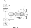
- FIG. 2 is a schematic diagram showing a combustion device according to this embodiment.
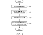
- FIG. 3 is a flow chart showing an example of the flow of processing performed by the control device according to the present embodiment.
- FIG. 4 is a schematic diagram showing a flame formed by the burner according to this embodiment.
- FIG. 5 is a schematic diagram showing a state in which the opening area of the injection port of the ammonia injection nozzle according to this embodiment is smaller than in the example of FIG.
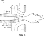
- FIG. 6 is a schematic diagram showing a combustion device according to a modification.
- FIG. 1 is a schematic diagram showing a boiler 1 according to this embodiment. As shown in FIG. 1, the boiler 1 includes a furnace 2, a flue 3, and burners 4.
- Furnace 2 is a furnace that burns fuel to generate combustion heat.
- An example in which ammonia and pulverized coal are used as fuels in the furnace 2 will be mainly described below. Carbon dioxide emissions are reduced by using ammonia and pulverized coal as fuel.
- the fuel used in the furnace 2 is not limited to this example.
- the furnace 2 has a vertically extending tubular shape (for example, a rectangular tubular shape).
- high-temperature combustion gas is generated by burning fuel.
- the bottom of the furnace 2 is provided with an outlet 2a for discharging ash generated by combustion of fuel to the outside.
- the flue 3 is a passage that guides the combustion gas generated in the furnace 2 to the outside as exhaust gas.
- a flue 3 is connected to the upper part of the furnace 2 .
- the flue 3 has a horizontal flue 3a and a rear flue 3b.
- a horizontal flue 3 a extends horizontally from the top of the furnace 2 .
- a rear flue 3b extends downward from the end of the horizontal flue 3a.
- the boiler 1 has a superheater (not shown) installed above the furnace 2 or the like. In the superheater, heat is exchanged between the combustion heat generated in the furnace 2 and water. Water vapor is thereby generated.
- the boiler 1 may be equipped with various devices (eg, reheater, economizer, air preheater, etc.) not shown in FIG.
- the burner 4 is provided on the lower wall of the furnace 2.
- a plurality of burners 4 are provided in the furnace 2 at intervals in the circumferential direction of the furnace 2 . Although not shown in FIG. 1, the plurality of burners 4 are also spaced apart in the extending direction of the furnace 2 (vertical direction).
- the burner 4 injects ammonia and pulverized coal as fuel into the furnace 2 .
- a flame F is formed in the furnace 2 by burning the fuel injected from the burner 4 .
- the furnace 2 is provided with an ignition device (not shown) for igniting the fuel injected from the burner 4 .
- FIG. 2 is a schematic diagram showing the combustion device 100 according to this embodiment.
- the combustion device 100 includes a burner 4, an air supply unit 5, an adjustment mechanism 6, an ammonia tank 7, an ammonia flow meter 8, an exhaust gas analyzer 9, and a control device 10. .
- the burner 4 is attached to the wall of the furnace 2 outside the furnace 2 .
- the burner 4 has an ammonia injection nozzle 41 and a pulverized coal injection nozzle 42 .
- the ammonia injection nozzle 41 is a nozzle that injects ammonia.
- the pulverized coal injection nozzle 42 is a nozzle that injects pulverized coal.
- the ammonia injection nozzle 41 and the pulverized coal injection nozzle 42 have a cylindrical shape.
- the pulverized coal injection nozzle 42 is arranged coaxially with the ammonia injection nozzle 41 so as to surround the ammonia injection nozzle 41 .
- a double cylinder structure is formed by the ammonia injection nozzle 41 and the pulverized coal injection nozzle 42 .
- the central axes of the ammonia injection nozzle 41 and the pulverized coal injection nozzle 42 intersect (specifically, substantially perpendicular to) the wall of the furnace 2 .
- the radial direction of the burner 4, the axial direction of the burner 4, and the circumferential direction of the burner 4 are also simply referred to as the radial direction, the axial direction, and the circumferential direction.
- the furnace 2 side of the burner 4 (the right side in FIG. 2) is called the front end side, and the opposite side of the burner 4 to the furnace 2 side (the left side in FIG. 2) is called the rear end side.
- the ammonia injection nozzle 41 includes a main body 41a and an injection port 41b.
- the main body 41a has a cylindrical shape.
- the central axis of the main body 41a intersects (more specifically, substantially perpendicular to) the wall of the furnace 2 .
- the main body 41a has a shape that tapers toward the distal end.
- a supply port (not shown) is provided in the rear portion (that is, the portion on the rear end side) of the main body 41a.
- a supply port of the ammonia injection nozzle 41 is connected to the ammonia tank 7 .
- An injection port 41b which is an opening, is formed at the tip of the main body 41a.
- the injection port 41 b faces the internal space of the furnace 2 . In other words, the injection port 41b faces the internal space of the furnace 2 .
- Ammonia is supplied from the ammonia tank 7 into the main body 41a through a supply port (not shown). As indicated by the arrow A1, the ammonia supplied into the main body 41a flows through the space between the inner peripheral portion of the main body 41a and the valve body 61 of the adjustment mechanism 6, which will be described later. The ammonia that has passed through the main body 41a is injected toward the internal space of the furnace 2 from the injection port 41b. Thus, the ammonia injection nozzle 41 is provided toward the inner space of the furnace 2 .
- the pulverized coal injection nozzle 42 includes a main body 42a and an injection port 42b.
- the main body 42a has a cylindrical shape.
- the main body 42a is arranged coaxially with the main body 41a of the ammonia injection nozzle 41 so as to surround the main body 41a.
- the main body 42a has a shape that tapers toward the distal end.
- a supply port (not shown) is provided in the rear portion (that is, the portion on the rear end side) of the main body 42a.
- the supply port of the pulverized coal injection nozzle 42 is connected to a pulverized coal supply source (not shown).
- An injection port 42b which is an opening, is formed at the tip of the main body 42a.
- the axial position of the tip of the main body 42 a substantially coincides with the axial position of the tip of the main body 41 a of the ammonia injection nozzle 41 .
- the injection port 42 b is an annular opening between the tip of the main body 42 a and the tip of the main body 41 a of the ammonia injection nozzle 41 .
- the injection port 42 b faces the internal space of the furnace 2 . In other words, the injection port 42b faces the internal space of the furnace 2 .
- Pulverized coal is supplied from a pulverized coal supply source into the main body 42a through a supply port (not shown) together with air for transporting the pulverized coal.
- the pulverized coal supplied into the main body 42a flows together with the air in the space between the inner peripheral portion of the main body 42a and the outer peripheral portion of the main body 41a of the ammonia injection nozzle 41.
- the pulverized coal that has passed through the main body 42a is injected toward the internal space of the furnace 2 from the injection port 42b.
- the pulverized coal injection nozzle 42 is provided toward the interior space of the furnace 2 .
- the air supply unit 5 supplies combustion air from the outside in the radial direction to the flame formed by the burner 4 (see flame F in FIG. 1).
- the air supply unit 5 is arranged so as to cover the space between the tip of the burner 4 and the furnace 2 .
- a flow path 51 through which air flows is formed in the air supply portion 5 .
- the channel 51 is formed in a cylindrical shape coaxial with the burner 4 .
- the flow path 51 is connected to an air supply source (not shown).
- An injection port 52 is formed at the end of the flow path 51 on the furnace 2 side.
- the air supplied from the air supply source to the air supply unit 5 passes through the flow path 51 and is injected from the injection port 52 toward the internal space of the furnace 2.
- the injection port 52 faces the internal space of the furnace 2 . That is, the injection port 52 faces the internal space of the furnace 2 .
- the air supply unit 5 is provided toward the inner space of the furnace 2 .
- the air injected from the injection port 52 of the air supply unit 5 advances toward the inner space of the furnace 2 while swirling in the circumferential direction.
- the adjustment mechanism 6 adjusts the opening area of the injection port 41 b of the ammonia injection nozzle 41 .
- the adjustment mechanism 6 has a valve body 61 and a drive device 62 .
- the configuration of the adjustment mechanism 6 is not limited to this example.
- the valve body 61 includes a shaft portion 61a and a cone portion 61b.
- the valve body 61 may be solid or hollow.
- the shaft portion 61 a extends along the central axis of the burner 4 .
- the shaft portion 61a is arranged coaxially with the main body 41a of the ammonia injection nozzle 41 so as to be surrounded by the main body 41a.
- the shaft portion 61a penetrates the rear portion of the main body 41a of the ammonia injection nozzle 41 and protrudes rearward.
- the cone portion 61b is attached to the tip of the shaft portion 61a.
- the cone portion 61b has a shape (conical shape in the example of FIG. 2) that tapers toward the distal end side.
- the cone portion 61b is positioned near the tip of the main body 41a of the ammonia injection nozzle 41 in the axial direction.
- the driving device 62 moves the valve body 61 in the axial direction.
- the driving device 62 includes a mechanism that guides the movement of the shaft portion 61a in the axial direction and a device that generates power (for example, a motor or the like).
- the driving device 62 can axially move the valve body 61 by transmitting power to the rear portion of the shaft portion 61a.
- the injection of the ammonia injection nozzle 41 The mouth 41b is a circular opening defined by the inner periphery of the tip of the main body 41a. Therefore, the opening area of the injection port 41b of the ammonia injection nozzle 41 is the area of the circular opening defined by the inner periphery of the tip of the main body 41a. In this case, the opening area of the injection port 41b is maximized.
- the injection port 41b of the ammonia injection nozzle 41 is located at the tip of the main body 41a. It becomes an annular opening defined between the inner peripheral portion and the outer peripheral portion of the cone portion 61b. Therefore, the opening area of the injection port 41b of the ammonia injection nozzle 41 is the area of the annular opening defined between the inner peripheral portion of the tip of the main body 41a and the outer peripheral portion of the cone portion 61b. In this case, the opening area of the injection port 41b is smaller than when the injection port 41b has a circular opening.
- the adjustment mechanism 6 can adjust the opening area of the injection port 41b of the ammonia injection nozzle 41 by moving the valve body 61 in the axial direction with the driving device 62.
- nitrogen oxides (NOx) are reduced by providing the adjustment mechanism 6 in the combustion device 100 . The action and effect of NOx reduction by the adjustment mechanism 6 will be described later.
- the ammonia flow meter 8 measures the flow rate of ammonia supplied from the ammonia tank 7 to the ammonia injection nozzle 41 .
- a measurement result by the ammonia flow meter 8 is output to the control device 10 .
- the exhaust gas analyzer 9 analyzes the components of the exhaust gas, which is the combustion gas discharged from the furnace 2. Analysis results by the exhaust gas analyzer 9 are output to the control device 10 .
- the control device 10 includes a central processing unit (CPU), a ROM storing programs and the like, a RAM as a work area, and the like, and controls the combustion device 100 as a whole.
- controller 10 controls the operation of adjustment mechanism 6 .
- the current axial position of the valve body 61 is output from the adjustment mechanism 6 to the control device 10 .
- the control device 10 can control the operation of the adjusting mechanism 6 based on the output result of the adjusting mechanism 6 so that the axial position of the valve body 61 becomes the target position.
- FIG. 3 is a flowchart showing an example of the flow of processing performed by the control device 10 according to this embodiment.
- the processing flow shown in FIG. 3 is repeatedly executed at set time intervals, for example.
- step S101 the control device 10 acquires the flow rate of ammonia (hereinafter also referred to as the ammonia flow rate) in the ammonia injection nozzle 41.
- the control device 10 acquires the result of measurement by the ammonia flow meter 8 as the flow rate of ammonia in the ammonia injection nozzle 41 .
- step S102 the control device 10 sets the target position (specifically, the target axial position) of the valve body 61 based on the ammonia flow rate.
- the controller 10 sets a position closer to the internal space of the furnace 2 as the target position of the valve body 61 as the ammonia flow rate decreases.
- step S103 the control device 10 acquires the current position of the valve body 61 (specifically, the current axial position). For example, the control device 10 acquires the current position of the valve body 61 from the adjustment mechanism 6 .
- step S104 the control device 10 controls the driving device 62 so that the axial position of the valve body 61 reaches the target position, and the processing flow shown in FIG. 3 ends.
- step S104 for example, if there is a difference between the current position of the valve body 61 and the target position, the control device 10 moves the valve body 61 so that the difference disappears.
- the control device 10 controls the operation of the drive device 62 so that the valve body 61 moves toward the inside of the furnace 2 as the ammonia flow rate decreases. Thereby, the control device 10 can control the operation of the adjusting mechanism 6 so that the opening area of the injection port 41b of the ammonia injection nozzle 41 becomes smaller as the ammonia flow rate becomes smaller.
- FIG. 4 is a schematic diagram showing the flame F formed by the burner 4 according to this embodiment.
- ammonia is injected from the ammonia injection nozzle 41
- pulverized coal is injected from the pulverized coal injection nozzle 42
- combustion air is supplied from the air supply section 5 , so that the flame F is generated in front of the burner 4 . It is formed.
- the flame F thus formed has a reduction zone, which is the zone in which NOx is reduced.
- the reduction region exists, for example, radially outside of the region where the flame F is formed.
- the mixed combustion rate of ammonia (ratio of ammonia in the fuel injected from the burner 4) may be changed.
- the flow rate of ammonia supplied to the ammonia injection nozzle 41 that is, the ammonia flow rate
- the flow rate of ammonia that is, ammonia flow rate
- the injection speed of ammonia injected from the ammonia injection nozzle 41 decreases.
- the ammonia injected from the ammonia injection nozzle 41 may not be sufficiently supplied to the reduction region of the flame F, and NOx in the exhausted combustion gas may increase.
- FIG. 5 is a schematic diagram showing a state in which the opening area of the injection port 41b of the ammonia injection nozzle 41 according to this embodiment is smaller than in the example of FIG.
- the ammonia flow rate is smaller than in the example of FIG. Therefore, the valve body 61 moves toward the inside of the furnace 2 compared to the example of FIG. As a result, the injection port 41b is constricted by the cone portion 61b, and the opening area of the injection port 41b is reduced. Therefore, a decrease in the ammonia injection speed due to a decrease in the ammonia flow rate is suppressed. Therefore, the injection speed of ammonia can be maintained at the same level as in the example of FIG. Therefore, if ammonia is sufficiently supplied to the reduction region of the flame F in the example of FIG. 4, ammonia is also sufficiently supplied to the reduction region of the flame F in the example of FIG. In this way, a reduction in NOx is properly achieved.
- the combustion device 100 includes the adjustment mechanism 6 that adjusts the opening area of the injection port 41b of the ammonia injection nozzle 41. This suppresses a decrease in the injection speed of ammonia due to changes in operating conditions, thereby reducing NOx. In particular, by controlling the operation of the adjustment mechanism 6 based on the ammonia flow rate, the reduction of NOx is appropriately realized.
- a measured value of NOx in the exhaust gas discharged from the furnace 2 is obtained based on the analysis result of the exhaust gas analyzer 9, for example.
- the measured values of NOx in the exhaust gas are accumulated as data when the opening area of the injection port 41b is changed variously with respect to the same ammonia flow rate.
- a map is created that defines the relationship between the flow rate of ammonia and the opening area of the injection port 41b so that NOx in the exhaust gas is effectively reduced.
- the controller 10 controls the adjustment mechanism 6 so that the relationship between the flow rate of ammonia and the opening area of the injection port 41b becomes the relationship indicated by the created map. NOx is thereby more effectively reduced.
- control device 10 may control the operation of the adjustment mechanism 6 based on various parameters other than the ammonia flow rate.
- controller 10 may control the operation of adjustment mechanism 6 based on other parameters described below in addition to the ammonia flow rate.
- control device 10 may control the operation of the adjustment mechanism 6 based on other parameters described below. Examples of various parameters that can be used to control the adjustment mechanism 6 are described below.
- the control device 10 may control the operation of the adjustment mechanism 6 based on the flow rate of pulverized coal in the pulverized coal injection nozzle 42 (hereinafter also referred to as pulverized coal flow rate). For example, the control device 10 controls the operation of the adjusting mechanism 6 such that the larger the pulverized coal flow rate, the smaller the opening area of the injection port 41b. As the pulverized coal flow rate increases, the air flow rate for conveying the pulverized coal increases. Therefore, the ammonia injected from the ammonia injection nozzle 41 is dragged by the air injected from the pulverized coal injection nozzle 42, and becomes difficult to spread over the entire flame F. Therefore, by reducing the opening area of the injection port 41b, the injection speed of ammonia increases, and ammonia is easily supplied to the reduction region of the flame F.
- the control device 10 may control the operation of the adjustment mechanism 6 based on the air flow rate in the air supply section 5 (hereinafter also referred to as the supplied air flow rate). For example, the control device 10 controls the operation of the adjustment mechanism 6 so that the opening area of the injection port 41b becomes smaller as the supply air flow rate increases. As the supply air flow rate increases, the ammonia injected from the ammonia injection nozzle 41 is dragged by the air injected from the air supply unit 5, and becomes less likely to spread over the entire flame F. Therefore, by reducing the opening area of the injection port 41b, the injection speed of ammonia increases, and ammonia is easily supplied to the reduction region of the flame F.
- the control device 10 may control the operation of the adjustment mechanism 6 based on the temperature in the inner space of the furnace 2 (hereinafter also referred to as the furnace temperature). For example, the control device 10 controls the operation of the adjustment mechanism 6 so that the opening area of the injection port 41b becomes smaller as the furnace temperature increases. As the in-furnace temperature increases, the air injected from the pulverized coal injection nozzle 42 and the air supply unit 5 expands and the flow rate of the air increases. Therefore, the ammonia injected from the ammonia injection nozzle 41 is dragged by the pulverized coal injection nozzle 42 and the air injected from the air supply unit 5, and is less likely to spread over the entire flame F. Therefore, by reducing the opening area of the injection port 41b, the injection speed of ammonia increases, and ammonia is easily supplied to the reduction region of the flame F.
- the furnace temperature the temperature in the inner space of the furnace 2
- the control device 10 controls the operation of the adjustment mechanism 6 so that the opening area of the injection port 41b becomes smaller as the
- an oil burner for example, is used as the ignition device of the furnace 2.
- the oil burner ignites by injecting oil into the inner space of the furnace 2 .
- the oil burner is provided in some burners 4 (specifically, the lowest burner 4 among the plurality of burners 4 arranged in the vertical direction).
- the oil burner extends on the central axis of burner 4 .
- the burner 4 described above with reference to FIG. 2 and the like is a burner without an oil burner.
- the burner provided with the oil burner may be provided with the adjustment mechanism 6 .
- an oil burner may be provided so as to axially penetrate the valve body 61 .
- a mechanism in which an oil burner has an outer shape similar to that of the valve body 61 and the oil burner is provided movably in the axial direction instead of the valve body 61 may be used as the adjustment mechanism 6 .
- FIG. 6 is a schematic diagram showing a combustion device 100A according to a modification. As shown in FIG. 6, the combustion device 100A differs from the combustion device 100 described above in the configuration of the valve body of the adjustment mechanism.
- the adjustment mechanism 6A of the combustion device 100A has a valve body 161 different from the valve body 61 of the adjustment mechanism 6 described above.
- the adjusting mechanism 6A has a driving device 62, like the adjusting mechanism 6 described above.
- the opening area of the injection port 41b of the ammonia injection nozzle 41 is adjusted by moving the valve body 161 in the axial direction by the driving device 62, as in the adjustment mechanism 6 described above.
- the valve body 161 of the adjustment mechanism 6A includes a shaft portion 161a and a cone portion 161b.
- the shaft portion 161a extends along the central axis of the burner 4, like the shaft portion 61a of the valve body 61 described above.
- the cone portion 161b is attached to the tip of the shaft portion 161a.
- the cone portion 161b has a shape (conical shape in the example of FIG. 6) that tapers toward the tip side.
- the outer peripheral portion of the valve body 161 extends along the inner peripheral portion of the main body 41 a of the ammonia injection nozzle 41 . That is, the radial gap formed between the inner peripheral portion of the main body 41a and the outer peripheral portion of the valve body 161 is substantially constant regardless of the axial position.
- the shaft portion 161a has a shape that tapers toward the distal end side.
- the outer diameter of the tip of the shaft portion 161a substantially matches the outer diameter of the rear end of the cone portion 161b. That is, no step is provided between the shaft portion 161a and the cone portion 161b.
- the gap between the main body 41a and the valve body 161 is substantially constant regardless of the position in the axial direction, thereby smoothing the flow of ammonia in the main body 41a of the ammonia injection nozzle 41. can.
- smooth flow of ammonia in the main body 41a of the ammonia injection nozzle 41 is also achieved by not providing a step on the outer peripheral portion of the valve body 161.
- the adjustment mechanism 6 has the valve body 61 and the drive device 62, and the drive device 62 moves the valve body 61 in the axial direction to adjust the opening area of the injection port 41b of the ammonia injection nozzle 41.
- the adjustment mechanism 6 is not limited to the above example as long as it has a function of adjusting the opening area of the injection port 41b of the ammonia injection nozzle 41.
- the adjustment mechanism 6 may correspond to a mechanism having a drive device.
- a mechanism having the member and a driving device that drives the member is provided. It can correspond to the adjustment mechanism 6 .
- the pulverized coal injection nozzle 42 is arranged radially outside the ammonia injection nozzle 41 in the burner 4 and the ammonia injection nozzle 41 and the pulverized coal injection nozzle 42 form a double cylindrical structure has been described above.
- the configuration of the burner 4 is not limited to the above example.
- the pulverized coal injection nozzle 42 may be arranged radially inside the ammonia injection nozzle 41 .
- an air injection nozzle for injecting air for combustion may be added.
- the burner 4 has a triple-cylindrical structure, and of the spaces partitioned by the triple-cylindrical structure, the space on the center side serves as the channel for the ammonia, and the space adjacent to the channel for the ammonia in the radial direction outside. may be an air flow path, and a space adjacent to the air flow path on the radially outer side may be a pulverized coal flow path.
- the fuel used in the furnace 2 is not limited to the above example, as long as it contains at least ammonia.
- the fuel used with ammonia in the furnace 2 may be fuel other than pulverized coal (for example, natural gas or biomass). Further, for example, the fuel used in the furnace 2 may be only ammonia.
- boiler 2 furnace 4: burner 5: air supply section 6: adjustment mechanism 6A: adjustment mechanism 10: control device 41: ammonia injection nozzle 41b: injection port 42: pulverized coal injection nozzle 42b: injection port 52: injection port 100 : Combustion device 100A: Combustion device
Landscapes
- Engineering & Computer Science (AREA)
- Mechanical Engineering (AREA)
- General Engineering & Computer Science (AREA)
- Chemical & Material Sciences (AREA)
- Combustion & Propulsion (AREA)
- Control Of Steam Boilers And Waste-Gas Boilers (AREA)
- Gas Separation By Absorption (AREA)
Abstract
Description
Claims (6)
- 火炉の内部空間に噴射口が臨むアンモニア噴射ノズルを有するバーナと、
前記噴射口の開口面積を調整する調整機構と、
を備える、
燃焼装置。 - 前記アンモニア噴射ノズルにおけるアンモニアの流量が小さいほど、前記噴射口の前記開口面積が小さくなるように、前記調整機構の動作を制御する制御装置を備える、
請求項1に記載の燃焼装置。 - 前記バーナは、前記火炉の前記内部空間に噴射口が臨む微粉炭噴射ノズルを有し、
前記微粉炭噴射ノズルにおける微粉炭の流量に基づいて、前記調整機構の動作を制御する制御装置を備える、
請求項1または2に記載の燃焼装置。 - 前記火炉の前記内部空間に噴射口が臨む空気供給部を備え、
前記空気供給部における空気の流量に基づいて、前記調整機構の動作を制御する制御装置を備える、
請求項1から3のいずれか一項に記載の燃焼装置。 - 前記火炉の前記内部空間における温度に基づいて、前記調整機構の動作を制御する制御装置を備える、
請求項1から4のいずれか一項に記載の燃焼装置。 - 請求項1から5のいずれか一項に記載の燃焼装置を備えるボイラ。
Priority Applications (5)
| Application Number | Priority Date | Filing Date | Title |
|---|---|---|---|
| JP2023500571A JP7616342B2 (ja) | 2021-02-19 | 2021-12-13 | 燃焼装置およびボイラ |
| KR1020237025076A KR102853264B1 (ko) | 2021-02-19 | 2021-12-13 | 연소 장치 및 보일러 |
| DE112021005738.3T DE112021005738T5 (de) | 2021-02-19 | 2021-12-13 | Verbrennungsvorrichtung und Kessel |
| AU2021428797A AU2021428797B2 (en) | 2021-02-19 | 2021-12-13 | Combustion device and boiler |
| US18/318,851 US20230288061A1 (en) | 2021-02-19 | 2023-05-17 | Combustion device and boiler |
Applications Claiming Priority (2)
| Application Number | Priority Date | Filing Date | Title |
|---|---|---|---|
| JP2021-025116 | 2021-02-19 | ||
| JP2021025116 | 2021-02-19 |
Related Child Applications (1)
| Application Number | Title | Priority Date | Filing Date |
|---|---|---|---|
| US18/318,851 Continuation US20230288061A1 (en) | 2021-02-19 | 2023-05-17 | Combustion device and boiler |
Publications (1)
| Publication Number | Publication Date |
|---|---|
| WO2022176347A1 true WO2022176347A1 (ja) | 2022-08-25 |
Family
ID=82930568
Family Applications (1)
| Application Number | Title | Priority Date | Filing Date |
|---|---|---|---|
| PCT/JP2021/045795 Ceased WO2022176347A1 (ja) | 2021-02-19 | 2021-12-13 | 燃焼装置およびボイラ |
Country Status (6)
| Country | Link |
|---|---|
| US (1) | US20230288061A1 (ja) |
| JP (1) | JP7616342B2 (ja) |
| KR (1) | KR102853264B1 (ja) |
| AU (1) | AU2021428797B2 (ja) |
| DE (1) | DE112021005738T5 (ja) |
| WO (1) | WO2022176347A1 (ja) |
Cited By (2)
| Publication number | Priority date | Publication date | Assignee | Title |
|---|---|---|---|---|
| CN115949936A (zh) * | 2022-11-01 | 2023-04-11 | 天津大学 | 一种喷水加氢的超低氮氨煤混烧气固相两相燃烧器 |
| WO2024057819A1 (ja) * | 2022-09-16 | 2024-03-21 | 三菱重工業株式会社 | 石炭アンモニア混焼ボイラ制御装置、石炭アンモニア混焼ボイラ制御方法、及び、石炭アンモニア混焼ボイラ制御プログラム |
Citations (4)
| Publication number | Priority date | Publication date | Assignee | Title |
|---|---|---|---|---|
| JPS58193011A (ja) * | 1982-05-06 | 1983-11-10 | Babcock Hitachi Kk | スラリ−液体燃料兼用バ−ナ |
| JP2018138863A (ja) * | 2017-02-24 | 2018-09-06 | 株式会社Ihi | 燃焼器及びボイラ |
| JP2019086191A (ja) * | 2017-11-02 | 2019-06-06 | 株式会社Ihi | ボイラ |
| JP2019086188A (ja) * | 2017-11-02 | 2019-06-06 | 株式会社Ihi | ボイラ |
Family Cites Families (11)
| Publication number | Priority date | Publication date | Assignee | Title |
|---|---|---|---|---|
| WO1996041948A1 (en) * | 1995-06-09 | 1996-12-27 | Zexel Corporation | Fuel injection nozzle having a variable nozzle hole area |
| US20120177553A1 (en) * | 2010-12-07 | 2012-07-12 | Lindemann Scott H | Injector And Method For Reducing Nox Emissions From Boilers, IC Engines and Combustion Processes |
| US8911699B2 (en) * | 2012-08-14 | 2014-12-16 | Clearsign Combustion Corporation | Charge-induced selective reduction of nitrogen |
| JP6772868B2 (ja) * | 2017-01-31 | 2020-10-21 | 株式会社Ihi | 燃焼装置及びガスタービン |
| JP6926581B2 (ja) * | 2017-03-27 | 2021-08-25 | 株式会社Ihi | 燃焼装置及びガスタービン |
| JP6772925B2 (ja) * | 2017-03-27 | 2020-10-21 | 株式会社Ihi | 燃焼装置及びガスタービンエンジンシステム |
| JP6906381B2 (ja) * | 2017-07-03 | 2021-07-21 | 株式会社東芝 | 燃焼装置およびガスタービン |
| JP7027817B2 (ja) | 2017-11-02 | 2022-03-02 | 株式会社Ihi | 燃焼装置及びボイラ |
| JP6813533B2 (ja) * | 2018-05-22 | 2021-01-13 | 三菱パワー株式会社 | バーナおよび燃焼装置 |
| JP7485500B2 (ja) * | 2018-09-11 | 2024-05-16 | 株式会社Ihi | 燃焼装置及びボイラ |
| JP7293034B2 (ja) | 2019-08-08 | 2023-06-19 | 株式会社東芝 | 水電解装置及び水電解装置の制御方法 |
-
2021
- 2021-12-13 KR KR1020237025076A patent/KR102853264B1/ko active Active
- 2021-12-13 AU AU2021428797A patent/AU2021428797B2/en active Active
- 2021-12-13 JP JP2023500571A patent/JP7616342B2/ja active Active
- 2021-12-13 WO PCT/JP2021/045795 patent/WO2022176347A1/ja not_active Ceased
- 2021-12-13 DE DE112021005738.3T patent/DE112021005738T5/de active Pending
-
2023
- 2023-05-17 US US18/318,851 patent/US20230288061A1/en active Pending
Patent Citations (4)
| Publication number | Priority date | Publication date | Assignee | Title |
|---|---|---|---|---|
| JPS58193011A (ja) * | 1982-05-06 | 1983-11-10 | Babcock Hitachi Kk | スラリ−液体燃料兼用バ−ナ |
| JP2018138863A (ja) * | 2017-02-24 | 2018-09-06 | 株式会社Ihi | 燃焼器及びボイラ |
| JP2019086191A (ja) * | 2017-11-02 | 2019-06-06 | 株式会社Ihi | ボイラ |
| JP2019086188A (ja) * | 2017-11-02 | 2019-06-06 | 株式会社Ihi | ボイラ |
Cited By (2)
| Publication number | Priority date | Publication date | Assignee | Title |
|---|---|---|---|---|
| WO2024057819A1 (ja) * | 2022-09-16 | 2024-03-21 | 三菱重工業株式会社 | 石炭アンモニア混焼ボイラ制御装置、石炭アンモニア混焼ボイラ制御方法、及び、石炭アンモニア混焼ボイラ制御プログラム |
| CN115949936A (zh) * | 2022-11-01 | 2023-04-11 | 天津大学 | 一种喷水加氢的超低氮氨煤混烧气固相两相燃烧器 |
Also Published As
| Publication number | Publication date |
|---|---|
| AU2021428797A1 (en) | 2023-06-22 |
| AU2021428797A9 (en) | 2025-03-20 |
| KR102853264B1 (ko) | 2025-08-29 |
| JP7616342B2 (ja) | 2025-01-17 |
| JPWO2022176347A1 (ja) | 2022-08-25 |
| DE112021005738T5 (de) | 2023-08-31 |
| KR20230122660A (ko) | 2023-08-22 |
| US20230288061A1 (en) | 2023-09-14 |
| AU2021428797B2 (en) | 2025-01-02 |
Similar Documents
| Publication | Publication Date | Title |
|---|---|---|
| US12331926B2 (en) | Combustion device and boiler | |
| JP7027817B2 (ja) | 燃焼装置及びボイラ | |
| JP7498654B2 (ja) | バーナ及びその制御方法、並びに、燃焼炉 | |
| JP6950464B2 (ja) | ボイラ | |
| US20230288061A1 (en) | Combustion device and boiler | |
| US20240230085A9 (en) | Combustion device and boiler | |
| US20230288062A1 (en) | Combustion device and boiler | |
| US20230296244A1 (en) | Combustion device and boiler | |
| JP7816486B2 (ja) | 燃焼装置 | |
| JP6429471B2 (ja) | 蓄熱式バーナ及び金属加熱炉 | |
| KR102893433B1 (ko) | 복합 연소 버너 및 이를 포함하는 연소 장치 |
Legal Events
| Date | Code | Title | Description |
|---|---|---|---|
| 121 | Ep: the epo has been informed by wipo that ep was designated in this application |
Ref document number: 21926772 Country of ref document: EP Kind code of ref document: A1 |
|
| ENP | Entry into the national phase |
Ref document number: 2023500571 Country of ref document: JP Kind code of ref document: A |
|
| ENP | Entry into the national phase |
Ref document number: 2021428797 Country of ref document: AU Date of ref document: 20211213 Kind code of ref document: A |
|
| ENP | Entry into the national phase |
Ref document number: 20237025076 Country of ref document: KR Kind code of ref document: A |
|
| 122 | Ep: pct application non-entry in european phase |
Ref document number: 21926772 Country of ref document: EP Kind code of ref document: A1 |