WO2022176019A1 - 映像符号化方法、映像符号化装置、及び映像符号化プログラム - Google Patents
映像符号化方法、映像符号化装置、及び映像符号化プログラム Download PDFInfo
- Publication number
- WO2022176019A1 WO2022176019A1 PCT/JP2021/005727 JP2021005727W WO2022176019A1 WO 2022176019 A1 WO2022176019 A1 WO 2022176019A1 JP 2021005727 W JP2021005727 W JP 2021005727W WO 2022176019 A1 WO2022176019 A1 WO 2022176019A1
- Authority
- WO
- WIPO (PCT)
- Prior art keywords
- blocks
- block
- image
- combined
- cost value
- Prior art date
- Legal status (The legal status is an assumption and is not a legal conclusion. Google has not performed a legal analysis and makes no representation as to the accuracy of the status listed.)
- Ceased
Links
Images










Classifications
-
- H—ELECTRICITY
- H04—ELECTRIC COMMUNICATION TECHNIQUE
- H04N—PICTORIAL COMMUNICATION, e.g. TELEVISION
- H04N19/00—Methods or arrangements for coding, decoding, compressing or decompressing digital video signals
- H04N19/10—Methods or arrangements for coding, decoding, compressing or decompressing digital video signals using adaptive coding
- H04N19/102—Methods or arrangements for coding, decoding, compressing or decompressing digital video signals using adaptive coding characterised by the element, parameter or selection affected or controlled by the adaptive coding
- H04N19/103—Selection of coding mode or of prediction mode
- H04N19/11—Selection of coding mode or of prediction mode among a plurality of spatial predictive coding modes
-
- H—ELECTRICITY
- H04—ELECTRIC COMMUNICATION TECHNIQUE
- H04N—PICTORIAL COMMUNICATION, e.g. TELEVISION
- H04N19/00—Methods or arrangements for coding, decoding, compressing or decompressing digital video signals
- H04N19/10—Methods or arrangements for coding, decoding, compressing or decompressing digital video signals using adaptive coding
- H04N19/102—Methods or arrangements for coding, decoding, compressing or decompressing digital video signals using adaptive coding characterised by the element, parameter or selection affected or controlled by the adaptive coding
- H04N19/119—Adaptive subdivision aspects, e.g. subdivision of a picture into rectangular or non-rectangular coding blocks
-
- H—ELECTRICITY
- H04—ELECTRIC COMMUNICATION TECHNIQUE
- H04N—PICTORIAL COMMUNICATION, e.g. TELEVISION
- H04N19/00—Methods or arrangements for coding, decoding, compressing or decompressing digital video signals
- H04N19/10—Methods or arrangements for coding, decoding, compressing or decompressing digital video signals using adaptive coding
- H04N19/134—Methods or arrangements for coding, decoding, compressing or decompressing digital video signals using adaptive coding characterised by the element, parameter or criterion affecting or controlling the adaptive coding
- H04N19/157—Assigned coding mode, i.e. the coding mode being predefined or preselected to be further used for selection of another element or parameter
-
- H—ELECTRICITY
- H04—ELECTRIC COMMUNICATION TECHNIQUE
- H04N—PICTORIAL COMMUNICATION, e.g. TELEVISION
- H04N19/00—Methods or arrangements for coding, decoding, compressing or decompressing digital video signals
- H04N19/10—Methods or arrangements for coding, decoding, compressing or decompressing digital video signals using adaptive coding
- H04N19/169—Methods or arrangements for coding, decoding, compressing or decompressing digital video signals using adaptive coding characterised by the coding unit, i.e. the structural portion or semantic portion of the video signal being the object or the subject of the adaptive coding
- H04N19/17—Methods or arrangements for coding, decoding, compressing or decompressing digital video signals using adaptive coding characterised by the coding unit, i.e. the structural portion or semantic portion of the video signal being the object or the subject of the adaptive coding the unit being an image region, e.g. an object
- H04N19/176—Methods or arrangements for coding, decoding, compressing or decompressing digital video signals using adaptive coding characterised by the coding unit, i.e. the structural portion or semantic portion of the video signal being the object or the subject of the adaptive coding the unit being an image region, e.g. an object the region being a block, e.g. a macroblock
-
- H—ELECTRICITY
- H04—ELECTRIC COMMUNICATION TECHNIQUE
- H04N—PICTORIAL COMMUNICATION, e.g. TELEVISION
- H04N19/00—Methods or arrangements for coding, decoding, compressing or decompressing digital video signals
- H04N19/50—Methods or arrangements for coding, decoding, compressing or decompressing digital video signals using predictive coding
- H04N19/593—Methods or arrangements for coding, decoding, compressing or decompressing digital video signals using predictive coding involving spatial prediction techniques
Definitions
- the disclosed technique relates to a video encoding method, a video encoding device, and a video encoding program.
- H.264 VVC Very Video Coding
- each frame is first divided into basic coding units called CTUs (Coding Tree Units). This is MPEG-2 and H.264. It corresponds to MB (Macro Block) in H.264/AVC.
- CTUs Coding Tree Units
- Each CTU is further divided into units called CUs (Coding Units).
- CUs Coding Units
- each CTU is split based on recursive quadtree block partitioning (Quad Tree: hereinafter referred to as "QT partitioning"), which is a tree structure in which each node is branched into four branches. be done. Therefore, there are 8 ⁇ 8, 16 ⁇ 16, 32 ⁇ 32, and 64 ⁇ 64 candidates as possible CU sizes, and a CTU is configured by combining CUs of each size.
- PU Prediction Unit
- TU transformation processing unit
- each CTU is divided not only into quadtree block division, but also into binary tree block division (Binary Tree division, hereinafter referred to as "BT division ), and ternary tree block partitioning (hereinafter referred to as "TT partitioning"), which divides a block into three with a side ratio of 1:2:1 in the horizontal or vertical direction, has been added.
- BT division Binary Tree division
- TT partitioning ternary tree block partitioning
- the size of the CU in VVC is divided into rectangles and squares of various sizes, such as 32 ⁇ 4 and 8 ⁇ 16, obtained by dividing the original CTU by combining QT division, TT division, and BT division. , and a combination of these CU sizes constitutes a CTU. Therefore, in VVC, compared with HEVC and the like, it is possible to adopt a complicated block division shape that matches the pattern and characteristics of the frame to be encoded, and highly efficient encoding can be performed. In VVC, encoding such as prediction processing, frequency conversion, and quantization is performed for each CU (for example, Non-Patent Document 1).
- the encoder since the number of block division patterns in VVC is much larger than that in HEVC, the encoder performs encoding or simple evaluation on all division patterns, and the encoded result or simple evaluation is performed. An enormous amount of processing is required to compare the results and determine the size of the CU.
- the present invention has been made in view of such circumstances, and aims to reduce the amount of processing for determining block division in encoding while maintaining the intra-frame prediction mode according to the features of the original image.
- a first aspect of the present disclosure is a video encoding method for encoding an image in units of blocks obtained by dividing the image, dividing the image into blocks, obtaining an intra-image prediction mode predicted for each block, It is determined whether or not to combine a plurality of blocks with a combination pattern based on the intra-picture prediction modes of a plurality of blocks adjacent to at least one of the blocks, and if it is determined to combine, each combined combined block It is a video encoding method in which a computer executes the process of predicting the
- a second aspect of the present disclosure is a video encoding device that encodes an image in block units obtained by dividing an image, and includes a dividing unit that divides the image into blocks and an intra-image prediction mode predicted for each block.
- An acquisition unit that acquires and a combination pattern based on intra-image prediction modes of a plurality of blocks adjacent to at least one of the blocks determines whether or not to combine a plurality of blocks, and if it is determined to combine, and a combining unit that performs prediction for each combined block.
- a third aspect of the present disclosure is a video encoding program that encodes an image in units of blocks obtained by dividing the image, dividing the image into blocks, obtaining an intra-image prediction mode predicted for each block, It is determined whether or not to combine a plurality of blocks with a combination pattern based on the intra-picture prediction modes of a plurality of blocks adjacent to at least one of the blocks, and if it is determined to combine, each combined combined block It is a video encoding program for causing a computer to execute the process.
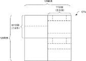
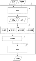
- FIG. 2 is a block diagram showing an example of a functional configuration of a video encoding device for explaining processing for encoding video according to each embodiment; It is a schematic diagram which shows an example of CTU with which it uses for description of division
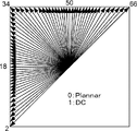
- FIG. 10 is a schematic diagram showing an example of a CTU for explaining divided CUs according to each embodiment; It is a figure which shows an example of the intra-picture prediction mode which concerns on each embodiment. It is a block diagram which shows an example of the hardware constitutions of the video encoding apparatus which concerns on each embodiment.
- FIG. 10 is a schematic diagram showing an example of a functional configuration of a video encoding device for explaining processing for encoding video according to each embodiment; It is a schematic diagram which shows an example of CTU with which it uses for description of division
- FIG. 10 is a schematic diagram showing an example of a CTU for explaining divided CUs according to each embodiment; It is
- FIG. 3 is a block diagram showing an example of the functional configuration of a CU division unit of the video encoding device according to the first embodiment; 4 is a data flow diagram showing an example of data flow in determination processing according to the first embodiment;
- FIG. It is a figure which shows an example of CU used for description of derivation
- FIG. 7 is a flow chart showing an example of the flow of determination processing for determining the block size of a CU according to the first embodiment
- 7 is a flow chart showing an example of the flow of combining processing for combining CUs according to the first embodiment
- FIG. 12 is a block diagram showing an example of the functional configuration of a CU division unit of the video encoding device according to the second embodiment
- FIG. 11 is a data flow diagram showing an example of data flow in determination processing according to the second embodiment
- FIG. 11 is a diagram showing an example of CUs for explaining a combination when rectangular CUs are included according to the second embodiment
- FIG. 11 is a flow chart showing an example of the flow of determination processing for determining the block size of a CU according to the second embodiment
- FIG. FIG. 11 is a flow chart showing an example of the flow of combining processing for combining CUs according to the second embodiment
- FIG. 1 is a block diagram showing an example of a functional configuration of a video encoding device 1 for explaining video encoding processing.
- the video encoding device 1 includes a CU division unit 10, a residual signal generation unit 11, a frequency conversion unit 12, a quantization unit 13, an entropy coding unit 14, an inverse quantization unit 15, an inverse frequency A transforming unit 16 , a decoded image generating unit 17 , a loop filtering unit 18 , a reference image buffering unit 19 , and a predicted image generating unit 20 are provided.
- the CU division unit 10 divides the CTU of the original image to be encoded into CUs, and determines the size of the CUs and the prediction mode of each CU.
- the original image is divided into CTUs each having a range of 128 pixels in the horizontal and vertical directions.
- the CTU is further divided into CUs, which are recursively divided blocks, and the processing of encoding the CUs as one unit is performed.
- the sizes of CTU and CU are assumed to be "(number of pixels in horizontal direction) ⁇ (number of pixels in vertical direction)".
- a CTU having a range of 128 pixels horizontally and vertically as one block is expressed as 128 ⁇ 128.
- the CTU is recursively divided into 4 blocks of 64 ⁇ 64, 32 ⁇ 32, 16 ⁇ 16, and 8 ⁇ 8 into CUs. may be divided into two or three horizontally or vertically. Therefore, as shown in FIG. 3 as an example, CTUs and CUs are divided into two, three, and four, and divided into CUs of respective sizes.
- the CU division unit 10 shown in FIG. 1 acquires an original image to be encoded and a decoded image from a reference image buffer unit 19 described later, and divides each CTU related to the original image into each CU described above. do.
- the CU division unit 10 outputs the original image divided into the size of each CU to the residual signal generation unit 11 and outputs the size of the CU and the prediction mode of the CU to the predicted image generation unit 20 .
- a method of dividing a CU and a method of deriving a prediction mode according to the present invention will be described in detail with reference to FIGS. 4 to 17 described later.
- the prediction mode which concerns on this embodiment demonstrates the form which is intra-picture prediction mode.
- the intra-picture prediction mode is a value for determining a block to refer to for encoding from blocks in an image that have been encoded before the block to be encoded.
- the direction in which the block to be referenced is located is determined in advance by the value of the prediction mode.
- the intra-picture prediction mode of VVC is the CU neighboring prediction mode from 65 directions between 45 degrees diagonally downward left (mode number 2) and 45 degrees diagonally upward right (mode number 66). There is a mode in which prediction is performed by referring to pixels.
- the intra-image prediction mode includes a Planar mode (mode number 0) in which prediction is performed using four points of adjacent pixels and a DC mode (mode number 1) in which an average of adjacent pixels is used.
- the intra-picture prediction mode is derived by past size determination processing and associated with each CU related to the reference image, and the intra-picture prediction mode corresponding to each CU is obtained from the reference image. The form will be explained.
- the residual signal generation unit 11 acquires the original image divided into each CU from the CU division unit 10, and acquires the prediction image corresponding to the original image divided into each CU from the prediction image generation unit 20.
- the residual signal generation unit 11 outputs the difference between the acquired CU in the original image and the CU in the predicted image corresponding to the CU of the original image to the frequency transform unit 12 as a prediction residual signal.
- the frequency transformation unit 12 acquires the prediction residual signal from the residual signal generation unit 11, and performs frequency transformation by discrete cosine transform or discrete sine transform on each of the horizontal direction of the predicted image and the vertical direction of the predicted image. .
- the frequency transformation unit 12 outputs the derived transformation coefficient group to the quantization unit 13 as a result of frequency transformation.
- the quantization unit 13 acquires the transform coefficient group from the frequency transform unit 12 and quantizes the transform coefficients using a predetermined quantization parameter.
- the quantization unit 13 outputs the quantized transform coefficients to the entropy coding unit 14 and the inverse quantization unit 15 .
- the entropy encoding unit 14 acquires the quantized transform coefficients from the quantization unit 13, entropy-encodes the quantized transform coefficients, and derives a bitstream.
- the entropy coding unit 14 outputs a bitstream derived as a result of entropy coding to an external device (not shown).
- the inverse quantization unit 15 acquires the quantized transform coefficients from the quantization unit 13, performs inverse quantization processing on the quantized transform coefficients, and generates transform coefficients.
- the inverse quantization unit 15 outputs transform coefficients to the inverse frequency transform unit 16 as a result of the inverse quantization process.
- the inverse frequency transform unit 16 acquires transform coefficients from the inverse quantization unit 15, performs inverse frequency transform on the transform coefficients, and generates prediction residual signals.
- the inverse frequency transformer 16 outputs the prediction residual signal to the decoded image generator 17 .
- the decoded image generation unit 17 acquires the prediction residual signal from the inverse frequency transform unit 16, and acquires the predicted image of the original image from the predicted image generation unit 20, which will be described later.
- the decoded image generation unit 17 generates a decoded image of the original image for each CU by adding the prediction residual signal to the prediction image for each CU.
- the decoded image generation unit 17 outputs the decoded image of the original image to the loop filter processing unit 18 and the reference image buffer unit 19 .
- the loop filtering unit 18 acquires the decoded image from the decoded image generating unit 17 and performs filtering on the decoded image to reduce encoding distortion.
- the loop filtering unit 18 outputs the filtered decoded image to the reference image buffer unit 19 .
- the reference image buffer unit 19 acquires the decoded image before filter processing from the decoded image generation unit 17 and acquires the decoded image after filter processing from the loop filter processing unit 18 .
- the reference image buffer unit 19 stores the acquired decoded image before filtering and the acquired decoded image after filtering as images for reference. That is, the reference image buffer unit 19 stores a decoded image obtained by decoding a past original image as a reference image.
- the predicted image generation unit 20 acquires the prediction mode of the CU related to the original image from the CU division unit 10, and acquires the past decoded image stored as the reference image from the reference image buffer unit 19.
- the predicted image generator 20 generates a predicted image of the original image based on the prediction mode of the original image and past decoded image data.
- the predicted image generator 20 outputs the predicted image to the residual signal generator 11 .
- FIG. 5 is a block diagram showing the hardware configuration of the video encoding device 1. As shown in FIG.
- the video encoding device 1 includes a CPU (Central Processing Unit) 31, a ROM (Read Only Memory) 32, a RAM (Random Access Memory) 33, a storage 34, an input section 35, a display section 36, and It has a communication interface (I/F) 37 .
- Each component is communicatively connected to each other via a bus 38 .
- the CPU 31 is a central processing unit that executes various programs and controls each section. That is, the CPU 31 reads a program from the ROM 32 or the storage 34 and executes the program using the RAM 33 as a work area. The CPU 31 performs control of the above components and various arithmetic processing according to programs stored in the ROM 32 or the storage 34 .
- the ROM 32 or the storage 34 stores a judgment processing program for judging the size of the CU related to the original image and a combination processing program for combining sub-blocks related to the original image. .
- the ROM 32 stores various programs and various data.
- the RAM 33 temporarily stores programs or data as a work area.
- the storage 34 is configured by a storage device such as a HDD (Hard Disk Drive) or SSD (Solid State Drive), and stores various programs including an operating system and various data.
- the input unit 35 includes a pointing device such as a mouse and a keyboard, and is used for various inputs.
- the display unit 36 is, for example, a liquid crystal display, and displays various information.
- the display unit 36 may employ a touch panel system and function as the input unit 35 .
- the communication interface 37 is an interface for communicating with other devices such as display devices.
- the communication uses, for example, a wired communication standard such as Ethernet (registered trademark) or FDDI, or a wireless communication standard such as 4G, 5G, or Wi-Fi (registered trademark).
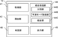
- FIG. 6 is a block diagram showing an example of the functional configuration of the CU dividing section 10 according to the video encoding device 1.
- FIG. 7 is a data flow diagram showing an example of the flow of data in the determination processing related to the function of the CU dividing unit 10. As shown in FIG.
- the CU division unit 10 includes an acquisition unit 41, a derivation unit 42, a determination unit 43, a combination processing unit 44, and an output unit 45 as functional configurations.
- the CPU 31 functions as an acquisition unit 41 , a derivation unit 42 , a determination unit 43 , a combination processing unit 44 and an output unit 45 by executing the determination processing program.
- the combination processing unit 44 includes a division unit 44A, a prediction mode acquisition unit 44B, and a combination unit 44C.
- the acquisition unit 41 acquires the input original image and the decoded image obtained by decoding the original image in the past.
- the derivation unit 42 derives the RD cost for a CU of a predetermined size from the acquired original image and decoded image.
- the CUs of predetermined size are CUs of 64 ⁇ 64, 32 ⁇ 32, 16 ⁇ 16, 8 ⁇ 8, and 4 ⁇ 4.
- the RD cost according to the present embodiment is a value that is obtained from the original image and the decoded image and indicates the amount of information and the coding error.
- the deriving unit 42 calculates the RDs of 4 ⁇ 4 CUs with base points (0, 0), (4, 0), (0, 4), and (4, 4).
- a value obtained by summing the costs (hereinafter referred to as "total cost value”) is derived.
- the deriving unit 42 calculates the RD cost of the CU to be determined as the RD cost of the 8 ⁇ 8 CU with (0, 0) including the four 4 ⁇ 4 CUs described above as the base point (hereinafter referred to as the “target cost value”).
- the derivation unit 42 further calculates 8 ⁇ 8 CUs with base points (0, 0), (8, 0), (0, 8), (8, 8) in the size range of 16 ⁇ 16 CUs. and a target cost value of a 16 ⁇ 16 CU starting from (0, 0) that includes the four 8 ⁇ 8 CUs.
- the derivation unit similarly derives the total cost value and the target cost value in the 32 ⁇ 32 CU size range and the 64 ⁇ 64 CU size range, and performs the above-described processing on the 64 ⁇ 64 recursively until it derives the target cost value for the CU of .
- the derivation unit 42 recursively performs the same processing in the range of the next 64 ⁇ 64 CU (for example, adjacent CU), recursively until all CUs are processed.
- the determination unit 43 shown in FIG. 7 compares the total cost value obtained by summing the RD costs of the four CUs derived by the derivation unit 42 and the target cost value of the CU containing the four CUs, It is determined whether or not the target cost value is less than or equal to the total cost value. As an example, the determination unit 43 compares the total cost value of four 4 ⁇ 4 CUs with the target cost value of an 8 ⁇ 8 CU that includes the four 4 ⁇ 4 CUs, and determines the target cost value is less than or equal to the total cost value.
- the determination unit 43 determines, as an 8 ⁇ 8 determination, the total cost value in four 4 ⁇ 4 CUs and the target in an 8 ⁇ 8 CU containing four 4 ⁇ 4 CUs Compare cost values. Next, the determination unit 43 compares the total cost value in four 8 ⁇ 8 CUs and the target cost value in a 16 ⁇ 16 CU including four 8 ⁇ 8 CUs as a 16 ⁇ 16 determination. . Similarly, the determination unit 43 performs 32 ⁇ 32 determination and 64 ⁇ 64 determination. In other words, the determination unit 43 performs determination by recursively comparing the total cost value and the target cost while enlarging the size of the CU to be determined from a small CU to a large CU. The determination unit 43 performs determination recursively until all CUs included in the CTU are processed.
- the combining processing unit 44 combines blocks related to the target CU, and derives the size of the combined CU, the RD cost of the CU, and the prediction mode of the CU. do.
- the dividing unit 44A associated with the combining processing unit 44 horizontally and vertically divides the target CU into 16 sub-blocks by dividing each into 4 sub-blocks.
- the dividing unit 44A divides the target CU into four subblocks by dividing each into two in the horizontal direction and the vertical direction.
- the prediction mode acquisition unit 44B in the combination processing unit 44 derives and acquires the prediction mode variation Vi of combination candidates obtained by combining the sub-blocks in each pattern.
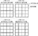
- the combination pattern means sub-patterns such that the target CU is horizontally BT-divided, vertically BT-divided, horizontally TT-divided, and vertically TT-divided.
- Each pattern is a combination of blocks. That is, the prediction mode acquisition unit 44B obtains each combination candidate when the target CU is BT-divided in the horizontal direction, BT-divided in the vertical direction, TT-divided in the horizontal direction, and TT-divided in the vertical direction. , the prediction mode variation Vi is derived. Note that, when the target CU is an 8 ⁇ 8 CU, the prediction mode acquisition unit 44B derives the variation Vi for each combination candidate when the BT split is performed in the horizontal direction and the BT split in the vertical direction.
- V is the degree of variation in the prediction mode of the combination candidate
- the prediction mode variation Vi is the variance value of the prediction modes of the sub-blocks included in the combination candidates.
- the prediction mode variation Vi is the sum of the absolute values of the prediction mode differences between the sub-blocks contained in the combined candidates, or the difference between the maximum value and the minimum value of the prediction modes in the sub-blocks. may
- the combining unit 44C in the combining processing unit 44 shown in FIG. 6 identifies the minimum variation Vi from all the derived variations Vi of the prediction modes, and when the identified variation Vi is equal to or less than the threshold, the pattern related to the identified variation Vi is determined as the pattern to be combined.
- the combining unit 44C combines the sub-blocks by using the combination candidates according to the determined pattern as combined CUs, and derives the RD cost and the prediction mode of the combined CUs. Also, if the identified variation Vi exceeds the threshold, the combining unit 44C does not combine the sub-blocks.
- CUs subjected to QT partitioning are combined to form a shape when BT partitioning or TT partitioning is performed, and based on the prediction mode of the combined CU, the shape when BT partitioning or TT partitioning is performed is the shape of the CU. It is determined whether or not to use the shape.
- the variance is equal to or less than a predetermined threshold, an example of merging is given.
- the threshold according to the present embodiment will be described as a positive natural number equal to or greater than 0.
- the prediction mode variation Vi is the variance value
- the intra-image prediction modes (mode numbers) of the four sub-blocks are 11, 12, 13, and 14 indicating approximately the same direction
- the prediction mode variation Vi becomes 1.6.
- the intra-picture prediction modes (mode numbers) of the four sub-blocks are 10, 20, 30, and 40 indicating different directions
- the prediction mode variation Vi is 166.6. That is, when the prediction mode variation Vi is the variance value, the intra-picture prediction modes that indicate roughly the same direction have a small variance value, and the intra-picture prediction modes that indicate different directions have a large variance value.
- the threshold is set to a small value (for example, from 1 to 9) so as to combine sub-blocks related to intra-picture prediction modes showing roughly the same direction and not combine sub-blocks related to intra-picture prediction modes showing different directions. value of any one of them) may be set.
- the prediction mode of the combined CU will be described as an average value of the prediction modes of the sub-blocks related to the combined CU. However, it is not limited to this. It may be the mode of the prediction mode of the sub-blocks associated with the combined CU. For example, if the prediction mode is the average value of the prediction modes of the sub-blocks, then in the sub-blocks of the four pre-combined CUs, if the prediction modes of each sub-block are 11, 12, 14, and 15, then after combining , the prediction mode of the CU is 13, which is the average value.
- the prediction mode is the mode of the prediction mode of the sub-block
- the prediction mode of each sub-block is 10, 10, 12, and 14, then the combination
- the prediction mode of the later CU is 10, which is the mode.
- the RD cost of the combined CU is a value obtained by adding or subtracting a predetermined value to or from the total value of the RD costs of the sub-blocks related to the combined CU.
- the RD cost of the rectangular CU instead of actually encoding and deriving the RD cost of the rectangular CU after combination by adding or subtracting a predetermined value to or from the total value of the RD costs held by each sub-block before combination, It can be easily derived using the already derived RD cost.
- FIG. 10 when joining in a region in a joining candidate involves splitting CUs in that region, the joining is not performed. In other words, when all CUs related to the merged CU are included in the merged candidate, the CUs within the area of the merged candidate are merged.
- the output unit 45 shown in FIG. 7 uses the original image divided into the size of each CU, the size of each CU, the RD cost of each CU, and the prediction mode of each CU as division information. 1 to the residual signal generator 11 .
- the output unit 45 outputs the size of the target CU, the RD cost of the target CU, and the prediction mode of the target CU. to output Further, when the determination unit 43 determines that the target cost value exceeds the total cost value, the output unit 45 outputs the size of the combined CU, the RD cost derived by the combination processing unit 44, and the combination processing The prediction mode derived by the unit 44 is output.
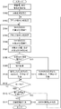
- FIG. 11 is a flowchart showing an example of determination processing according to this embodiment.
- the determination processing program shown in FIG. 11 is executed by the CPU 31 reading the determination processing program from the ROM 32 or the storage 34 and executing it.
- the determination processing program shown in FIG. 11 is executed, for example, when an original image is input and an instruction to execute encoding is input.
- step S101 the CPU 31 acquires original image data and decoded image data.
- step S102 the CPU 31 divides the original image into CTUs, divides the CTU into 64 ⁇ 64 units, and sets the target CU, which is the target range for determination.
- step S103 the CPU 31 sets the number of blocks N to 4.
- step S104 the CPU 31 derives a total cost value for a CU of size N ⁇ N.
- the total cost value in the N ⁇ N size CU according to the present embodiment is 4 ⁇ 4, 8 ⁇ 8, 16 ⁇ 16, and 32 ⁇ 32 CU sizes, and the sum of four CUs is This is the sum of the RD costs.
- step S105 the CPU 31 multiplies N by 2 to obtain the size of the target CU that is one size larger.
- step S106 the CPU 31 takes a CU of size N ⁇ N as a target CU and derives the target cost value of the target CU.
- the CPU 31 sets the 8 ⁇ 8 size CU as the target CU. Thereafter, each time steps S104 and S105 are repeated, the CPU 31 increases the size of the target CU to 16 ⁇ 16, 32 ⁇ 32, and finally 64 ⁇ 64.
- step S107 the CPU 31 compares the target cost value and the total cost value as N ⁇ N determination.
- the target cost value is the RD cost value in an 8 ⁇ 8 target CU
- the total cost value obtained by adding up the RD costs of four 4 ⁇ 4 CUs included in the target CU, and 8 ⁇ 8 with the target cost value, which is the RD cost in the target CU of 8.
- step S108 the CPU 31 determines whether or not the target cost value exceeds the total cost value.
- the target cost value exceeds the combined cost value (step S108: YES)
- the CPU 31 proceeds to step S109.
- the target cost value does not exceed the total cost value (the target cost value is equal to or less than the total cost value) (step S108: NO)
- the CPU 31 proceeds to step S111.
- step S109 the CPU 31 performs combining processing for combining sub-blocks obtained by dividing the CU into a predetermined number.
- a plurality of CUs split by QT splitting are joined to obtain a rectangular CU shape like that obtained by BT splitting or TT splitting. Note that the merging process according to this embodiment will be described in detail with reference to FIG. 12, which will be described later.
- step S110 the CPU 31 associates and stores the combined CU size, RD cost, and prediction mode.
- step S111 the CPU 31 associates and stores the size of the N ⁇ N CU, the RD cost, and the prediction mode.
- step S112 the CPU 31 determines whether or not the number of blocks N is 64. When the number of blocks N is 64 (step S112: YES), the CPU 31 proceeds to step S113. On the other hand, if the number of blocks N is not 64 (step S112: NO), the CPU 31 proceeds to step S104.
- step S113 the CPU 31 determines whether or not all ranges have been compared in the set target range. If all ranges have been compared (step S113: YES), the CPU 31 proceeds to step S114. On the other hand, if all ranges have not been compared (step S113: NO), the CPU 31 proceeds to step S115.
- step S114 the CPU 31 outputs the original image, the size of all CUs in the original image, the RD cost, and the prediction mode as division information.
- step S115 the CPU 31 sets the target CU, which is the target range for the next determination, and proceeds to step S103.
- FIG. 12 is a flow chart showing an example of combining processing according to this embodiment.
- the CPU 31 reads the connection processing program from the ROM 32 or the storage 34 and executes it, thereby executing the connection processing program shown in FIG.
- the connection processing program shown in FIG. 12 is executed when an instruction to execute the connection processing is input.
- step S201 the CPU 31 divides the target CU into sub-blocks.
- the target CU is any one of 8x8, 16x16, 32x32, and 64x64 CUs. is divided into 16 divisions, and if the target CU is an 8 ⁇ 8 CU, it is divided into 4 divisions.
- step S202 the CPU 31 acquires the prediction mode of the sub-block.
- step S203 the CPU 31 acquires combination candidates obtained by combining sub-blocks for each combination pattern for the target CU. Note that when the target CU is a 16 ⁇ 16, 32 ⁇ 32, or 64 ⁇ 64 CU, the combination candidates for patterns 1 to 4 shown in FIG. 9 are acquired, and when the target CU is an 8 ⁇ 8 CU , pattern 1, and pattern 2 are obtained.
- step S204 the CPU 31 derives the prediction mode variation Vi for each combination candidate.
- step S205 the CPU 31 identifies the minimum prediction mode variation Vmin among the derived prediction mode variations Vi.
- step S206 the CPU 31 determines whether or not the specified minimum prediction mode variation Vmin is equal to or less than the threshold.
- the specified variation Vi of the prediction mode is equal to or less than the threshold (step S206: YES)
- the CPU 31 proceeds to step S207.
- the identified prediction mode variation Vi is not equal to or less than the threshold (prediction mode variation Vi exceeds the threshold) (step S206: NO)
- the CPU 31 terminates the combining process.
- step S207 the CPU 31 determines a pattern related to the specified prediction mode variation Vi as a pattern for combining sub-blocks.
- step S208 the CPU 31 combines the sub-blocks with the determined pattern as a combined CU.
- the combination changes the combination pattern of the combined CUs the CUs are not combined.
- step S209 the CPU 31 derives the combined CU RD cost and prediction mode.
- the CU containing the region tends to be split vertically, and the CUs vertically adjacent to the CU are similarly divided. More likely to split vertically. Therefore, in an area with an edge such as a line extending in the vertical direction, it may not be necessary to perform an evaluation that divides and combines the CU in the horizontal direction, so it is possible to reduce the amount of processing. be.
- the determination unit 43 recursively compares the total cost value and the target cost to perform determination while enlarging the size of the CU to be determined from a small CU to a large CU. explained. In the present embodiment, the determination unit 43 performs determination by recursively comparing the total cost value and the target cost while reducing the size of the CU to be determined from a large CU to a small CU. do.
- FIG. 1 A diagram showing an example of the functional configuration of the video encoding device 1 according to the present embodiment (see FIG. 1), a diagram showing an example of a CTU for explaining the division (see FIG. 2), and an explanation of the divided CUs.
- a diagram (see FIG. 3) showing an example of a CTU used for the above is the same as that of the first embodiment, so description thereof will be omitted.
- a diagram showing the hardware configuration of the video encoding device 1 according to the present embodiment see FIG. 5
- FIG. 8 a diagram showing an example of a CU containing four CUs (see FIG. 8), and a combination pattern are shown in FIG.
- FIG. 8 A diagram showing FIG.
- FIG. 10 showing an example of a CU for processing is the same as that of the first embodiment, and thus description thereof is omitted.
- FIG. 13 is a block diagram showing an example of the functional configuration of the CU division unit 10 according to the video encoding device 1.
- FIG. 14 is a data flow diagram showing an example of data flow in division processing. 13 that are the same as the functions of the CU dividing unit 10 shown in FIG. 6 are given the same reference numerals as in FIG. 6, and description thereof will be omitted. 14 that are the same as the functions of the CU dividing unit 10 shown in FIG. 7 are denoted by the same reference numerals as in FIG. 7, and description thereof will be omitted.
- the CU division unit 10 includes an acquisition unit 41, a derivation unit 42, a determination unit 46, a combination processing unit 44, and an output unit 45 as functional configurations.
- the CPU 31 functions as an acquisition unit 41 , a derivation unit 42 , a determination unit 46 , a combination processing unit 44 and an output unit 45 by executing the determination processing program.
- the combination processing unit 44 includes a division unit 44D, a prediction mode acquisition unit 44B, and a combination unit 44C.
- a determination unit 46 and a division unit 44D are different from the determination unit 43 and the division unit 44A of the first embodiment, respectively.
- the determination unit 46 shown in FIG. 14 compares the total cost value obtained by summing the RD costs of the four CUs derived by the derivation unit 42 and the target cost value of the CU containing the four CUs, It is determined whether or not the target cost value is less than or equal to the total cost value. As an example, the determination unit 46 compares the total cost value of four 32 ⁇ 32 CUs with the target cost value of a 64 ⁇ 64 CU that includes the four 32 ⁇ 32 CUs, and determines the target cost value is less than or equal to the total cost value.
- the determination unit 46 determines, as a 64 ⁇ 64 determination, the total cost value in four 32 ⁇ 32 CUs and the target cost value in a 64 ⁇ 64 CU including four 32 ⁇ 32 CUs. comparison. Next, the determination unit 46 compares the total cost value in four 16 ⁇ 16 CUs and the target cost value in a 32 ⁇ 32 CU including four 16 ⁇ 16 CUs as a 32 ⁇ 32 decision. . Similarly, the determination unit 46 performs 16 ⁇ 16 determination and 8 ⁇ 8 determination. That is, the determination unit 46 performs determination by recursively comparing the total cost value and the target cost while reducing the size of the CU to be determined from a large CU to a small CU.
- the determination unit 46 performs determination recursively until all CUs included in the CTU are processed. note that. By performing determination while reducing the size of the CU, it is possible to reduce the number of times of determination processing and the amount of processing compared to the case of performing determination while reducing the size of the CU. For example, the determination unit 46 performs 64 ⁇ 64 determination, and if it is determined that the target cost value in the 64 ⁇ 64 CU is small, the size of the target CU is determined to be 64 ⁇ 64, and the size of the target CU is determined to be 64 ⁇ 64. It is not necessary to perform the process of determining the included CU. In other words, the determining unit 46 determines that a large CU has a smaller RD cost than a divided CU, so there is no need to divide and combine a large CU.
- the combining processing unit 44 combines blocks related to the target CU, and derives the size of the combined CU, the RD cost of the CU, and the prediction mode of the CU. do.
- the division unit 44D associated with the joint processing unit 44 shown in FIG. 13 divides the target CU into 16 sub-blocks by dividing each into 4 in the horizontal direction and the vertical direction.
- the dividing unit 44D divides the target CU into four subblocks by dividing each of the target CU into two in the horizontal direction and the vertical direction.
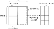
- the dividing unit 44D divides the rectangular CU into eight squares (for example, a 16 ⁇ 64 CU). 16 etc.) sub-blocks.
- the square sub-blocks are combined by a prediction mode acquisition unit 44B and a combining unit 44C.
- FIG. 16 is a flowchart showing an example of determination processing according to this embodiment.
- the determination processing program shown in FIG. 16 is executed by the CPU 31 reading the determination processing program from the ROM 32 or the storage 34 and executing it.
- the determination processing program shown in FIG. 16 is executed, for example, when an original image is input and an instruction to execute encoding is input. 16 that are the same as those in the determination process shown in FIG. 11 are denoted by the same reference numerals as in FIG. 11, and description thereof will be omitted.
- step S116 the CPU 31 sets 64 to the number N of blocks.
- step S117 the CPU 31 derives an N ⁇ N target cost value.
- the N ⁇ N target cost values according to the present embodiment are the target cost values of 8 ⁇ 8, 16 ⁇ 16, 32 ⁇ 32, and 64 ⁇ 64 CUs.
- step S118 the CPU 31 multiplies N by 1/2 to obtain the size of the target CU that is one size smaller.
- step S119 the CPU 31 derives the total cost value of the N ⁇ N CUs.
- the CPU 31 selects a 32 ⁇ 32 size CU as the target CU. Thereafter, each time steps S117 and S118 are repeated, the CPU 31 reduces the size of the target CU to 16 ⁇ 16, 8 ⁇ 8, and finally 4 ⁇ 4.
- step S120 the CPU 31 performs a merging process for merging CUs. Note that the combining process according to this embodiment will be described in detail with reference to FIG. 17, which will be described later.
- step S121 the CPU 31 determines whether or not the target CU is a 64 ⁇ 64 CU. If the target CU is a 64 ⁇ 64 CU (step S121: YES), the CPU 31 proceeds to step S113. On the other hand, if the target CU is not a 64 ⁇ 64 CU (step S121: NO), the CPU 31 proceeds to step S112.
- FIG. 17 is a flow chart showing an example of combining processing according to this embodiment.
- the CPU 31 reads the connection processing program from the ROM 32 or the storage 34 and executes it, thereby executing the connection processing program shown in FIG.
- the connection processing program shown in FIG. 17 is executed when an instruction to execute connection processing is input. 17 that are the same as those in the combining process shown in FIG. 12 are denoted by the same reference numerals as in FIG. 12, and description thereof will be omitted.
- step S210 the CPU 31 determines whether or not a rectangular CU is included among the target CUs to be combined. If a rectangular CU is not included (step S210: YES), the CPU 31 terminates the combining process. On the other hand, if a rectangular CU is included (step S210: NO), the CPU 31 proceeds to step S211.
- step S211 the CPU 31 sets the rectangular CU as a target CU to be combined, and proceeds to step S201.
- the display control device of the second embodiment performs CU size determination and CU coupling while reducing the determined CU size from a large CU to a small CU. This reduces the number of CU size determinations and the number of CU merging executions.
- VVC VVC using QT division, BT division, TT division, and the like.
- any encoding standard may be used as long as it divides into different shapes, such as QT division, BT division, and TT division, and encodes each divided unit.
- a configuration has been described in which the processing of judging the size and concatenating CUs that have undergone QT division is executed.
- a process of judging the size and combining may be performed on the CU that has undergone the BT splitting or the TT splitting.
- the CTU and the CU are divided into equal CUs by QT division, and H. This has the effect of facilitating execution of parallel processing incorporated in H.265/HEVC encoding.
- the display control processing executed by the CPU reading the software (program) in each of the above embodiments may be executed by various processors other than the CPU.
- the processor is a PLD (Programmable Logic Device) whose circuit configuration can be changed after manufacturing, such as an FPGA (Field-Programmable Gate Array), and an ASIC (Application Specific Integrated Circuit) to execute specific processing.
- a dedicated electric circuit or the like which is a processor having a specially designed circuit configuration, is exemplified.
- the display control processing may be executed by one of these various processors, or a combination of two or more processors of the same or different type (for example, multiple FPGAs and a combination of CPU and FPGA). etc.). More specifically, the hardware structure of these various processors is an electric circuit in which circuit elements such as semiconductor elements are combined.
- the display control processing program has been pre-stored (installed) in the storage 34, but the present invention is not limited to this.
- Programs are stored in non-transitory storage media such as CD-ROM (Compact Disk Read Only Memory), DVD-ROM (Digital Versatile Disk Read Only Memory), and USB (Universal Serial Bus) memory.
- CD-ROM Compact Disk Read Only Memory
- DVD-ROM Digital Versatile Disk Read Only Memory
- USB Universal Serial Bus
- a display controller configured to:
- Appendix 2 A non-temporary storage medium storing a program executable by a computer to perform video encoding processing, The video encoding process for encoding the image in units of blocks obtained by dividing the image, dividing the image into blocks; obtaining an intra-picture prediction mode predicted for each block; It is determined whether or not to combine the plurality of blocks with a combination pattern based on the intra-picture prediction modes of a plurality of blocks adjacent to at least one of the blocks, and if it is determined to combine, the combined combined block make a prediction every Non-transitory storage media.
Landscapes
- Engineering & Computer Science (AREA)
- Multimedia (AREA)
- Signal Processing (AREA)
- Compression Or Coding Systems Of Tv Signals (AREA)
Abstract
Description
まず、図1から図3を参照して、映像符号化装置1によって、映像を符号化する処理について説明する。図1は、映像を符号化する処理の説明に供する映像符号化装置1の機能構成の一例を示すブロック図である。
第1実施形態では、判定部43において、小さいCUから大きいCUへと、判定するCUの大きさを拡大しながら、再帰的に合算コスト値と、対象コストと、を比較して判定を行う形態について説明した。本実施形態では、判定部43において、大きいCUから小さいCUへと判定するCUの大きさを縮小しながら、再帰的に合算コスト値と、対象コストと、を比較して判定を行う形態について説明する。
メモリと、
前記メモリに接続された少なくとも1つのプロセッサと、
を含み、
前記プロセッサは、
画像を分割したブロック単位で画像の符号化を行う映像符号化方法であって、
前記画像をブロックに分割し、
前記ブロック毎に予測された画像内予測モードを取得し、
少なくとも何れかのブロックと隣接しあう複数のブロックの画像内予測モードに基づく結合パターンで、前記複数のブロックを結合するか否かを判定して、結合すると判定された場合、結合された結合ブロック毎に予測を行う、
ように構成されている表示制御装置。
映像符号化処理を実行するようにコンピュータによって実行可能なプログラムを記憶した非一時的記憶媒体であって、
画像を分割したブロック単位で前記画像の符号化を行う映像符号化処理は、
前記画像をブロックに分割し、
前記ブロック毎に予測された画像内予測モードを取得し、
少なくとも何れかのブロックと隣接しあう複数のブロックの画像内予測モードに基づく結合パターンで、前記複数のブロックを結合するか否かを判定して、結合すると判定された場合、結合された結合ブロック毎に予測を行う、
非一時的記憶媒体。
41 取得部
42 導出部
43、46 判定部
44 結合処理部
44A、44D 分割部
44B 予測モード取得部
44C 結合部
45 出力部
Claims (8)
- 画像を分割したブロック単位で前記画像の符号化を行う映像符号化方法であって、
前記画像をブロックに分割し、
前記ブロック毎に予測された画像内予測モードを取得し、
少なくとも何れかのブロックと隣接しあう複数のブロックの画像内予測モードに基づく結合パターンで、前記複数のブロックを結合するか否かを判定して、結合すると判定された場合、結合された結合ブロック毎に予測を行う、
処理をコンピュータが実行する映像符号化方法。 - 前記コンピュータは、
結合パターン毎に、予め定められた範囲の前記ブロックを結合候補として設定し、
前記結合候補における前記画像内予測モードのばらつき度合のうち、前記ばらつき度合が最小となる結合候補における前記結合パターンを前記画像内予測モードに応じた結合パターンとして決定する
請求項1に記載の映像符号化方法。 - 前記コンピュータは、
前記結合ブロックに係る前記ブロック間の前記画像内予測モードの差分和、又は前記結合ブロックに係る前記ブロックの前記画像内予測モードの分散を用いて、前記ばらつき度合を導出する
請求項2に記載の映像符号化方法。 - 前記コンピュータは、
前記結合候補として、前記ブロックを水平方向、又は垂直方向に、2分割、又は3分割した範囲を設定する、
請求項2又は請求項3に記載の映像符号化方法。 - 前記コンピュータは、
符号化を行う対象のブロックである対象ブロックのRDコスト値である対象コスト値、及び前記対象ブロックを予め定められた大きさのブロックに分割し、前記分割されたブロックの各々のRDコスト値を合算した合算コスト値を導出し、
前記対象コスト値が前記合算コスト値以下である場合、前記対象ブロックの大きさ、及び対象コスト値を出力し、
前記対象コスト値が前記合算コスト値を超える場合、前記対象ブロックを前記結合ブロックに分割し、前記結合ブロックの大きさ、及び前記結合ブロック毎のRDコスト値を出力する、
請求項1から請求項4の何れか1項に記載の映像符号化方法。 - 前記コンピュータは、
予め定められた前記対象ブロックの大きさ毎に、前記対象コスト値、及び前記合算コスト値の比較と、前記対象ブロックに内包される前記ブロックの結合と、を再帰的に実行する
請求項5に記載の映像符号化方法。 - 画像を分割したブロック単位で前記画像の符号化を行う映像符号化装置であって、
前記画像をブロックに分割する分割部と、
前記ブロック毎に予測された画像内予測モードを取得する取得部と、
少なくとも何れかのブロックと隣接しあう複数のブロックの画像内予測モードに基づく結合パターンで、前記複数のブロックを結合するか否かを判定して、結合すると判定された場合、結合された結合ブロック毎に予測を行う結合部と、
を備えた映像符号化装置。 - 画像を分割したブロック単位で前記画像の符号化を行う映像符号化プログラムであって、
前記画像をブロックに分割し、
前記ブロック毎に予測された画像内予測モードを取得し、
少なくとも何れかのブロックと隣接しあう複数のブロックの画像内予測モードに基づく結合パターンで、前記複数のブロックを結合するか否かを判定して、結合すると判定された場合、結合された結合ブロック毎に予測を行う、
処理をコンピュータに実行させるための映像符号化プログラム。
Priority Applications (3)
| Application Number | Priority Date | Filing Date | Title |
|---|---|---|---|
| PCT/JP2021/005727 WO2022176019A1 (ja) | 2021-02-16 | 2021-02-16 | 映像符号化方法、映像符号化装置、及び映像符号化プログラム |
| JP2023500147A JP7513184B2 (ja) | 2021-02-16 | 2021-02-16 | 映像符号化方法、映像符号化装置、及び映像符号化プログラム |
| US18/277,066 US12407819B2 (en) | 2021-02-16 | 2021-02-16 | Video coding method, video coding device, and video coding program |
Applications Claiming Priority (1)
| Application Number | Priority Date | Filing Date | Title |
|---|---|---|---|
| PCT/JP2021/005727 WO2022176019A1 (ja) | 2021-02-16 | 2021-02-16 | 映像符号化方法、映像符号化装置、及び映像符号化プログラム |
Publications (1)
| Publication Number | Publication Date |
|---|---|
| WO2022176019A1 true WO2022176019A1 (ja) | 2022-08-25 |
Family
ID=82931251
Family Applications (1)
| Application Number | Title | Priority Date | Filing Date |
|---|---|---|---|
| PCT/JP2021/005727 Ceased WO2022176019A1 (ja) | 2021-02-16 | 2021-02-16 | 映像符号化方法、映像符号化装置、及び映像符号化プログラム |
Country Status (3)
| Country | Link |
|---|---|
| US (1) | US12407819B2 (ja) |
| JP (1) | JP7513184B2 (ja) |
| WO (1) | WO2022176019A1 (ja) |
Citations (3)
| Publication number | Priority date | Publication date | Assignee | Title |
|---|---|---|---|---|
| JP2015181225A (ja) * | 2014-03-06 | 2015-10-15 | パナソニックIpマネジメント株式会社 | 動画像符号化装置および動画像符号化方法 |
| JP2017011458A (ja) * | 2015-06-19 | 2017-01-12 | 富士通株式会社 | 符号化データ生成プログラム、符号化データ生成方法および符号化データ生成装置 |
| WO2018047952A1 (ja) * | 2016-09-12 | 2018-03-15 | 日本電気株式会社 | イントラ予測モード決定方法、イントラ予測モード決定装置およびイントラ予測モード決定プログラムを記憶する記憶媒体 |
Family Cites Families (4)
| Publication number | Priority date | Publication date | Assignee | Title |
|---|---|---|---|---|
| JP5719410B2 (ja) * | 2013-07-25 | 2015-05-20 | 日本電信電話株式会社 | 画像符号化方法、画像符号化装置及び画像符号化プログラム |
| JP6268989B2 (ja) * | 2013-11-29 | 2018-01-31 | 富士通株式会社 | 動画像符号化装置、動画像符号化方法及び動画像符号化用コンピュータプログラム |
| US20160373744A1 (en) * | 2014-04-23 | 2016-12-22 | Sony Corporation | Image processing apparatus and image processing method |
| US11445203B2 (en) * | 2019-01-04 | 2022-09-13 | Qualcomm Incorporated | Sub-partition intra prediction in video coding |
-
2021
- 2021-02-16 JP JP2023500147A patent/JP7513184B2/ja active Active
- 2021-02-16 US US18/277,066 patent/US12407819B2/en active Active
- 2021-02-16 WO PCT/JP2021/005727 patent/WO2022176019A1/ja not_active Ceased
Patent Citations (3)
| Publication number | Priority date | Publication date | Assignee | Title |
|---|---|---|---|---|
| JP2015181225A (ja) * | 2014-03-06 | 2015-10-15 | パナソニックIpマネジメント株式会社 | 動画像符号化装置および動画像符号化方法 |
| JP2017011458A (ja) * | 2015-06-19 | 2017-01-12 | 富士通株式会社 | 符号化データ生成プログラム、符号化データ生成方法および符号化データ生成装置 |
| WO2018047952A1 (ja) * | 2016-09-12 | 2018-03-15 | 日本電気株式会社 | イントラ予測モード決定方法、イントラ予測モード決定装置およびイントラ予測モード決定プログラムを記憶する記憶媒体 |
Also Published As
| Publication number | Publication date |
|---|---|
| US20240114130A1 (en) | 2024-04-04 |
| JPWO2022176019A1 (ja) | 2022-08-25 |
| JP7513184B2 (ja) | 2024-07-09 |
| US12407819B2 (en) | 2025-09-02 |
Similar Documents
| Publication | Publication Date | Title |
|---|---|---|
| RU2666319C1 (ru) | Способ, устройство и система для кодирования и декодирования единицы кодирования | |
| JP2022033107A (ja) | ビデオ符号化での分割ブロック符号化方法、ビデオ復号化での分割ブロック復号化方法及びこれを実現する記録媒体 | |
| KR20250152542A (ko) | 영상 부호화/복호화 방법, 장치 및 비트스트림을 저장한 기록 매체 | |
| US10432956B2 (en) | Image coding device, image decoding device, image coding method, and image decoding method | |
| KR101801255B1 (ko) | 쿼드트리 구조 기반의 적응적 양자화 파라미터 부호화 및 복호화 방법 및 장치 | |
| JP2015507885A5 (ja) | ||
| US20210195191A1 (en) | Image encoding method/device, image decoding method/device and recording medium having bitstream stored therein | |
| CN113170117B (zh) | 一种视频编码/解码方法及装置 | |
| CN109936742A (zh) | 对视频序列进行编码的方法、编码装置和存储介质 | |
| KR20240161950A (ko) | 영상 신호 부호화/복호화 방법 및 장치 | |
| KR20240108465A (ko) | 비디오 인코딩 및 디코딩 방법 및 장치 | |
| US12348790B2 (en) | Entropy encoding and decoding apparatus and method for using the same | |
| JPWO2016194380A1 (ja) | 動画像符号化装置、動画像符号化方法および動画像符号化プログラムを記憶する記録媒体 | |
| JP7513184B2 (ja) | 映像符号化方法、映像符号化装置、及び映像符号化プログラム | |
| JP6176044B2 (ja) | ブロック構造決定回路および情報圧縮回路 | |
| CN115379222B (zh) | 影像编码/解码方法及装置 | |
| KR101648123B1 (ko) | 비디오 부호화에서의 분할 블록 부호화 방법, 비디오 복호화에서의 분할 블록 복호화 방법 및 이를 구현하는 기록매체 | |
| KR102728583B1 (ko) | 영상 신호 부호화/복호화 방법 및 장치 | |
| KR101644970B1 (ko) | 비디오 복호화에서의 분할 블록 복호화 방법 및 이를 구현하는 기록매체 | |
| KR101644967B1 (ko) | 비디오 복호화에서의 분할 블록 복호화 방법 및 이를 구현하는 기록매체 | |
| KR101644969B1 (ko) | 비디오 복호화에서의 분할 블록 복호화 방법 및 이를 구현하는 기록매체 | |
| WO2026009352A1 (ja) | 符号化装置 | |
| KR20170130334A (ko) | 쿼드트리 구조 기반의 적응적 양자화 파라미터 부호화 및 복호화 방법 및 장치 | |
| KR102628530B1 (ko) | 영상 부호화 또는 복호화하기 위한 장치 및 방법 | |
| KR101785431B1 (ko) | 비디오 복호화에서의 분할 블록 복호화 방법 및 이를 구현하는 기록매체 |
Legal Events
| Date | Code | Title | Description |
|---|---|---|---|
| 121 | Ep: the epo has been informed by wipo that ep was designated in this application |
Ref document number: 21926459 Country of ref document: EP Kind code of ref document: A1 |
|
| ENP | Entry into the national phase |
Ref document number: 2023500147 Country of ref document: JP Kind code of ref document: A |
|
| WWE | Wipo information: entry into national phase |
Ref document number: 18277066 Country of ref document: US |
|
| NENP | Non-entry into the national phase |
Ref country code: DE |
|
| 122 | Ep: pct application non-entry in european phase |
Ref document number: 21926459 Country of ref document: EP Kind code of ref document: A1 |
|
| WWG | Wipo information: grant in national office |
Ref document number: 18277066 Country of ref document: US |