WO2022172992A1 - Fuel cell system and fuel cell vehicle - Google Patents
Fuel cell system and fuel cell vehicle Download PDFInfo
- Publication number
- WO2022172992A1 WO2022172992A1 PCT/JP2022/005358 JP2022005358W WO2022172992A1 WO 2022172992 A1 WO2022172992 A1 WO 2022172992A1 JP 2022005358 W JP2022005358 W JP 2022005358W WO 2022172992 A1 WO2022172992 A1 WO 2022172992A1
- Authority
- WO
- WIPO (PCT)
- Prior art keywords
- fuel cell
- power
- generated
- cell vehicle
- power generation
- Prior art date
Links
- 239000000446 fuel Substances 0.000 title claims abstract description 523
- 238000010248 power generation Methods 0.000 claims abstract description 211
- 238000003860 storage Methods 0.000 claims abstract description 174
- 230000001133 acceleration Effects 0.000 claims description 70
- 238000001514 detection method Methods 0.000 claims description 16
- 239000003990 capacitor Substances 0.000 claims description 7
- 230000001172 regenerating effect Effects 0.000 claims description 7
- 238000004364 calculation method Methods 0.000 claims description 4
- UFHFLCQGNIYNRP-UHFFFAOYSA-N Hydrogen Chemical compound [H][H] UFHFLCQGNIYNRP-UHFFFAOYSA-N 0.000 description 38
- 238000000034 method Methods 0.000 description 29
- 239000001257 hydrogen Substances 0.000 description 28
- 229910052739 hydrogen Inorganic materials 0.000 description 28
- 230000008569 process Effects 0.000 description 24
- 230000007704 transition Effects 0.000 description 18
- XLYOFNOQVPJJNP-UHFFFAOYSA-N water Substances O XLYOFNOQVPJJNP-UHFFFAOYSA-N 0.000 description 18
- 230000006866 deterioration Effects 0.000 description 16
- 238000012545 processing Methods 0.000 description 13
- 230000009194 climbing Effects 0.000 description 12
- 230000007423 decrease Effects 0.000 description 11
- 239000002737 fuel gas Substances 0.000 description 10
- 238000006243 chemical reaction Methods 0.000 description 9
- 238000010586 diagram Methods 0.000 description 9
- 239000007789 gas Substances 0.000 description 8
- 239000007800 oxidant agent Substances 0.000 description 8
- 230000001590 oxidative effect Effects 0.000 description 8
- 230000008859 change Effects 0.000 description 7
- 230000001276 controlling effect Effects 0.000 description 7
- 239000007788 liquid Substances 0.000 description 6
- QVGXLLKOCUKJST-UHFFFAOYSA-N atomic oxygen Chemical compound [O] QVGXLLKOCUKJST-UHFFFAOYSA-N 0.000 description 5
- 239000001301 oxygen Substances 0.000 description 5
- 229910052760 oxygen Inorganic materials 0.000 description 5
- 239000003054 catalyst Substances 0.000 description 4
- 238000007599 discharging Methods 0.000 description 4
- 239000002826 coolant Substances 0.000 description 3
- 230000005611 electricity Effects 0.000 description 3
- 230000006870 function Effects 0.000 description 3
- 230000001105 regulatory effect Effects 0.000 description 3
- 238000003487 electrochemical reaction Methods 0.000 description 2
- 238000005259 measurement Methods 0.000 description 2
- 230000003071 parasitic effect Effects 0.000 description 2
- 239000012495 reaction gas Substances 0.000 description 2
- 230000009467 reduction Effects 0.000 description 2
- 239000003507 refrigerant Substances 0.000 description 2
- HBBGRARXTFLTSG-UHFFFAOYSA-N Lithium ion Chemical compound [Li+] HBBGRARXTFLTSG-UHFFFAOYSA-N 0.000 description 1
- 238000013459 approach Methods 0.000 description 1
- 238000004590 computer program Methods 0.000 description 1
- 239000000498 cooling water Substances 0.000 description 1
- 239000013078 crystal Substances 0.000 description 1
- 230000000694 effects Effects 0.000 description 1
- 230000005669 field effect Effects 0.000 description 1
- 230000017525 heat dissipation Effects 0.000 description 1
- 230000010354 integration Effects 0.000 description 1
- 229910001416 lithium ion Inorganic materials 0.000 description 1
- 238000004519 manufacturing process Methods 0.000 description 1
- 229910044991 metal oxide Inorganic materials 0.000 description 1
- 150000004706 metal oxides Chemical class 0.000 description 1
- 238000012986 modification Methods 0.000 description 1
- 230000004048 modification Effects 0.000 description 1
- 239000002245 particle Substances 0.000 description 1
- 239000005518 polymer electrolyte Substances 0.000 description 1
- 238000002360 preparation method Methods 0.000 description 1
- 230000005855 radiation Effects 0.000 description 1
- 230000000717 retained effect Effects 0.000 description 1
- 239000004065 semiconductor Substances 0.000 description 1
- 239000000126 substance Substances 0.000 description 1
Images


Classifications
-
- B—PERFORMING OPERATIONS; TRANSPORTING
- B60—VEHICLES IN GENERAL
- B60L—PROPULSION OF ELECTRICALLY-PROPELLED VEHICLES; SUPPLYING ELECTRIC POWER FOR AUXILIARY EQUIPMENT OF ELECTRICALLY-PROPELLED VEHICLES; ELECTRODYNAMIC BRAKE SYSTEMS FOR VEHICLES IN GENERAL; MAGNETIC SUSPENSION OR LEVITATION FOR VEHICLES; MONITORING OPERATING VARIABLES OF ELECTRICALLY-PROPELLED VEHICLES; ELECTRIC SAFETY DEVICES FOR ELECTRICALLY-PROPELLED VEHICLES
- B60L58/00—Methods or circuit arrangements for monitoring or controlling batteries or fuel cells, specially adapted for electric vehicles
- B60L58/40—Methods or circuit arrangements for monitoring or controlling batteries or fuel cells, specially adapted for electric vehicles for controlling a combination of batteries and fuel cells
-
- B—PERFORMING OPERATIONS; TRANSPORTING
- B60—VEHICLES IN GENERAL
- B60L—PROPULSION OF ELECTRICALLY-PROPELLED VEHICLES; SUPPLYING ELECTRIC POWER FOR AUXILIARY EQUIPMENT OF ELECTRICALLY-PROPELLED VEHICLES; ELECTRODYNAMIC BRAKE SYSTEMS FOR VEHICLES IN GENERAL; MAGNETIC SUSPENSION OR LEVITATION FOR VEHICLES; MONITORING OPERATING VARIABLES OF ELECTRICALLY-PROPELLED VEHICLES; ELECTRIC SAFETY DEVICES FOR ELECTRICALLY-PROPELLED VEHICLES
- B60L1/00—Supplying electric power to auxiliary equipment of vehicles
- B60L1/003—Supplying electric power to auxiliary equipment of vehicles to auxiliary motors, e.g. for pumps, compressors
-
- B—PERFORMING OPERATIONS; TRANSPORTING
- B60—VEHICLES IN GENERAL
- B60L—PROPULSION OF ELECTRICALLY-PROPELLED VEHICLES; SUPPLYING ELECTRIC POWER FOR AUXILIARY EQUIPMENT OF ELECTRICALLY-PROPELLED VEHICLES; ELECTRODYNAMIC BRAKE SYSTEMS FOR VEHICLES IN GENERAL; MAGNETIC SUSPENSION OR LEVITATION FOR VEHICLES; MONITORING OPERATING VARIABLES OF ELECTRICALLY-PROPELLED VEHICLES; ELECTRIC SAFETY DEVICES FOR ELECTRICALLY-PROPELLED VEHICLES
- B60L15/00—Methods, circuits, or devices for controlling the traction-motor speed of electrically-propelled vehicles
- B60L15/20—Methods, circuits, or devices for controlling the traction-motor speed of electrically-propelled vehicles for control of the vehicle or its driving motor to achieve a desired performance, e.g. speed, torque, programmed variation of speed
- B60L15/2009—Methods, circuits, or devices for controlling the traction-motor speed of electrically-propelled vehicles for control of the vehicle or its driving motor to achieve a desired performance, e.g. speed, torque, programmed variation of speed for braking
- B60L15/2018—Methods, circuits, or devices for controlling the traction-motor speed of electrically-propelled vehicles for control of the vehicle or its driving motor to achieve a desired performance, e.g. speed, torque, programmed variation of speed for braking for braking on a slope
-
- B—PERFORMING OPERATIONS; TRANSPORTING
- B60—VEHICLES IN GENERAL
- B60L—PROPULSION OF ELECTRICALLY-PROPELLED VEHICLES; SUPPLYING ELECTRIC POWER FOR AUXILIARY EQUIPMENT OF ELECTRICALLY-PROPELLED VEHICLES; ELECTRODYNAMIC BRAKE SYSTEMS FOR VEHICLES IN GENERAL; MAGNETIC SUSPENSION OR LEVITATION FOR VEHICLES; MONITORING OPERATING VARIABLES OF ELECTRICALLY-PROPELLED VEHICLES; ELECTRIC SAFETY DEVICES FOR ELECTRICALLY-PROPELLED VEHICLES
- B60L3/00—Electric devices on electrically-propelled vehicles for safety purposes; Monitoring operating variables, e.g. speed, deceleration or energy consumption
- B60L3/0023—Detecting, eliminating, remedying or compensating for drive train abnormalities, e.g. failures within the drive train
- B60L3/0046—Detecting, eliminating, remedying or compensating for drive train abnormalities, e.g. failures within the drive train relating to electric energy storage systems, e.g. batteries or capacitors
-
- B—PERFORMING OPERATIONS; TRANSPORTING
- B60—VEHICLES IN GENERAL
- B60L—PROPULSION OF ELECTRICALLY-PROPELLED VEHICLES; SUPPLYING ELECTRIC POWER FOR AUXILIARY EQUIPMENT OF ELECTRICALLY-PROPELLED VEHICLES; ELECTRODYNAMIC BRAKE SYSTEMS FOR VEHICLES IN GENERAL; MAGNETIC SUSPENSION OR LEVITATION FOR VEHICLES; MONITORING OPERATING VARIABLES OF ELECTRICALLY-PROPELLED VEHICLES; ELECTRIC SAFETY DEVICES FOR ELECTRICALLY-PROPELLED VEHICLES
- B60L50/00—Electric propulsion with power supplied within the vehicle
- B60L50/40—Electric propulsion with power supplied within the vehicle using propulsion power supplied by capacitors
-
- B—PERFORMING OPERATIONS; TRANSPORTING
- B60—VEHICLES IN GENERAL
- B60L—PROPULSION OF ELECTRICALLY-PROPELLED VEHICLES; SUPPLYING ELECTRIC POWER FOR AUXILIARY EQUIPMENT OF ELECTRICALLY-PROPELLED VEHICLES; ELECTRODYNAMIC BRAKE SYSTEMS FOR VEHICLES IN GENERAL; MAGNETIC SUSPENSION OR LEVITATION FOR VEHICLES; MONITORING OPERATING VARIABLES OF ELECTRICALLY-PROPELLED VEHICLES; ELECTRIC SAFETY DEVICES FOR ELECTRICALLY-PROPELLED VEHICLES
- B60L50/00—Electric propulsion with power supplied within the vehicle
- B60L50/50—Electric propulsion with power supplied within the vehicle using propulsion power supplied by batteries or fuel cells
- B60L50/51—Electric propulsion with power supplied within the vehicle using propulsion power supplied by batteries or fuel cells characterised by AC-motors
-
- B—PERFORMING OPERATIONS; TRANSPORTING
- B60—VEHICLES IN GENERAL
- B60L—PROPULSION OF ELECTRICALLY-PROPELLED VEHICLES; SUPPLYING ELECTRIC POWER FOR AUXILIARY EQUIPMENT OF ELECTRICALLY-PROPELLED VEHICLES; ELECTRODYNAMIC BRAKE SYSTEMS FOR VEHICLES IN GENERAL; MAGNETIC SUSPENSION OR LEVITATION FOR VEHICLES; MONITORING OPERATING VARIABLES OF ELECTRICALLY-PROPELLED VEHICLES; ELECTRIC SAFETY DEVICES FOR ELECTRICALLY-PROPELLED VEHICLES
- B60L50/00—Electric propulsion with power supplied within the vehicle
- B60L50/50—Electric propulsion with power supplied within the vehicle using propulsion power supplied by batteries or fuel cells
- B60L50/70—Electric propulsion with power supplied within the vehicle using propulsion power supplied by batteries or fuel cells using power supplied by fuel cells
- B60L50/72—Constructional details of fuel cells specially adapted for electric vehicles
-
- B—PERFORMING OPERATIONS; TRANSPORTING
- B60—VEHICLES IN GENERAL
- B60L—PROPULSION OF ELECTRICALLY-PROPELLED VEHICLES; SUPPLYING ELECTRIC POWER FOR AUXILIARY EQUIPMENT OF ELECTRICALLY-PROPELLED VEHICLES; ELECTRODYNAMIC BRAKE SYSTEMS FOR VEHICLES IN GENERAL; MAGNETIC SUSPENSION OR LEVITATION FOR VEHICLES; MONITORING OPERATING VARIABLES OF ELECTRICALLY-PROPELLED VEHICLES; ELECTRIC SAFETY DEVICES FOR ELECTRICALLY-PROPELLED VEHICLES
- B60L50/00—Electric propulsion with power supplied within the vehicle
- B60L50/50—Electric propulsion with power supplied within the vehicle using propulsion power supplied by batteries or fuel cells
- B60L50/75—Electric propulsion with power supplied within the vehicle using propulsion power supplied by batteries or fuel cells using propulsion power supplied by both fuel cells and batteries
-
- B—PERFORMING OPERATIONS; TRANSPORTING
- B60—VEHICLES IN GENERAL
- B60L—PROPULSION OF ELECTRICALLY-PROPELLED VEHICLES; SUPPLYING ELECTRIC POWER FOR AUXILIARY EQUIPMENT OF ELECTRICALLY-PROPELLED VEHICLES; ELECTRODYNAMIC BRAKE SYSTEMS FOR VEHICLES IN GENERAL; MAGNETIC SUSPENSION OR LEVITATION FOR VEHICLES; MONITORING OPERATING VARIABLES OF ELECTRICALLY-PROPELLED VEHICLES; ELECTRIC SAFETY DEVICES FOR ELECTRICALLY-PROPELLED VEHICLES
- B60L58/00—Methods or circuit arrangements for monitoring or controlling batteries or fuel cells, specially adapted for electric vehicles
- B60L58/10—Methods or circuit arrangements for monitoring or controlling batteries or fuel cells, specially adapted for electric vehicles for monitoring or controlling batteries
- B60L58/12—Methods or circuit arrangements for monitoring or controlling batteries or fuel cells, specially adapted for electric vehicles for monitoring or controlling batteries responding to state of charge [SoC]
- B60L58/15—Preventing overcharging
-
- B—PERFORMING OPERATIONS; TRANSPORTING
- B60—VEHICLES IN GENERAL
- B60L—PROPULSION OF ELECTRICALLY-PROPELLED VEHICLES; SUPPLYING ELECTRIC POWER FOR AUXILIARY EQUIPMENT OF ELECTRICALLY-PROPELLED VEHICLES; ELECTRODYNAMIC BRAKE SYSTEMS FOR VEHICLES IN GENERAL; MAGNETIC SUSPENSION OR LEVITATION FOR VEHICLES; MONITORING OPERATING VARIABLES OF ELECTRICALLY-PROPELLED VEHICLES; ELECTRIC SAFETY DEVICES FOR ELECTRICALLY-PROPELLED VEHICLES
- B60L7/00—Electrodynamic brake systems for vehicles in general
- B60L7/10—Dynamic electric regenerative braking
- B60L7/14—Dynamic electric regenerative braking for vehicles propelled by ac motors
-
- B—PERFORMING OPERATIONS; TRANSPORTING
- B60—VEHICLES IN GENERAL
- B60L—PROPULSION OF ELECTRICALLY-PROPELLED VEHICLES; SUPPLYING ELECTRIC POWER FOR AUXILIARY EQUIPMENT OF ELECTRICALLY-PROPELLED VEHICLES; ELECTRODYNAMIC BRAKE SYSTEMS FOR VEHICLES IN GENERAL; MAGNETIC SUSPENSION OR LEVITATION FOR VEHICLES; MONITORING OPERATING VARIABLES OF ELECTRICALLY-PROPELLED VEHICLES; ELECTRIC SAFETY DEVICES FOR ELECTRICALLY-PROPELLED VEHICLES
- B60L7/00—Electrodynamic brake systems for vehicles in general
- B60L7/10—Dynamic electric regenerative braking
- B60L7/18—Controlling the braking effect
-
- H—ELECTRICITY
- H01—ELECTRIC ELEMENTS
- H01M—PROCESSES OR MEANS, e.g. BATTERIES, FOR THE DIRECT CONVERSION OF CHEMICAL ENERGY INTO ELECTRICAL ENERGY
- H01M8/00—Fuel cells; Manufacture thereof
-
- H—ELECTRICITY
- H01—ELECTRIC ELEMENTS
- H01M—PROCESSES OR MEANS, e.g. BATTERIES, FOR THE DIRECT CONVERSION OF CHEMICAL ENERGY INTO ELECTRICAL ENERGY
- H01M8/00—Fuel cells; Manufacture thereof
- H01M8/04—Auxiliary arrangements, e.g. for control of pressure or for circulation of fluids
-
- H—ELECTRICITY
- H01—ELECTRIC ELEMENTS
- H01M—PROCESSES OR MEANS, e.g. BATTERIES, FOR THE DIRECT CONVERSION OF CHEMICAL ENERGY INTO ELECTRICAL ENERGY
- H01M8/00—Fuel cells; Manufacture thereof
- H01M8/04—Auxiliary arrangements, e.g. for control of pressure or for circulation of fluids
- H01M8/04082—Arrangements for control of reactant parameters, e.g. pressure or concentration
- H01M8/04089—Arrangements for control of reactant parameters, e.g. pressure or concentration of gaseous reactants
- H01M8/04111—Arrangements for control of reactant parameters, e.g. pressure or concentration of gaseous reactants using a compressor turbine assembly
-
- H—ELECTRICITY
- H01—ELECTRIC ELEMENTS
- H01M—PROCESSES OR MEANS, e.g. BATTERIES, FOR THE DIRECT CONVERSION OF CHEMICAL ENERGY INTO ELECTRICAL ENERGY
- H01M8/00—Fuel cells; Manufacture thereof
- H01M8/04—Auxiliary arrangements, e.g. for control of pressure or for circulation of fluids
- H01M8/04298—Processes for controlling fuel cells or fuel cell systems
- H01M8/04313—Processes for controlling fuel cells or fuel cell systems characterised by the detection or assessment of variables; characterised by the detection or assessment of failure or abnormal function
- H01M8/0432—Temperature; Ambient temperature
- H01M8/04373—Temperature; Ambient temperature of auxiliary devices, e.g. reformers, compressors, burners
-
- H—ELECTRICITY
- H01—ELECTRIC ELEMENTS
- H01M—PROCESSES OR MEANS, e.g. BATTERIES, FOR THE DIRECT CONVERSION OF CHEMICAL ENERGY INTO ELECTRICAL ENERGY
- H01M8/00—Fuel cells; Manufacture thereof
- H01M8/04—Auxiliary arrangements, e.g. for control of pressure or for circulation of fluids
- H01M8/04298—Processes for controlling fuel cells or fuel cell systems
- H01M8/04313—Processes for controlling fuel cells or fuel cell systems characterised by the detection or assessment of variables; characterised by the detection or assessment of failure or abnormal function
- H01M8/04537—Electric variables
- H01M8/04604—Power, energy, capacity or load
- H01M8/04619—Power, energy, capacity or load of fuel cell stacks
-
- H—ELECTRICITY
- H01—ELECTRIC ELEMENTS
- H01M—PROCESSES OR MEANS, e.g. BATTERIES, FOR THE DIRECT CONVERSION OF CHEMICAL ENERGY INTO ELECTRICAL ENERGY
- H01M8/00—Fuel cells; Manufacture thereof
- H01M8/04—Auxiliary arrangements, e.g. for control of pressure or for circulation of fluids
- H01M8/04298—Processes for controlling fuel cells or fuel cell systems
- H01M8/04313—Processes for controlling fuel cells or fuel cell systems characterised by the detection or assessment of variables; characterised by the detection or assessment of failure or abnormal function
- H01M8/04537—Electric variables
- H01M8/04604—Power, energy, capacity or load
- H01M8/04626—Power, energy, capacity or load of auxiliary devices, e.g. batteries, capacitors
-
- H—ELECTRICITY
- H01—ELECTRIC ELEMENTS
- H01M—PROCESSES OR MEANS, e.g. BATTERIES, FOR THE DIRECT CONVERSION OF CHEMICAL ENERGY INTO ELECTRICAL ENERGY
- H01M8/00—Fuel cells; Manufacture thereof
- H01M8/04—Auxiliary arrangements, e.g. for control of pressure or for circulation of fluids
- H01M8/04298—Processes for controlling fuel cells or fuel cell systems
- H01M8/04694—Processes for controlling fuel cells or fuel cell systems characterised by variables to be controlled
- H01M8/04701—Temperature
- H01M8/04738—Temperature of auxiliary devices, e.g. reformer, compressor, burner
-
- H—ELECTRICITY
- H01—ELECTRIC ELEMENTS
- H01M—PROCESSES OR MEANS, e.g. BATTERIES, FOR THE DIRECT CONVERSION OF CHEMICAL ENERGY INTO ELECTRICAL ENERGY
- H01M8/00—Fuel cells; Manufacture thereof
- H01M8/04—Auxiliary arrangements, e.g. for control of pressure or for circulation of fluids
- H01M8/04298—Processes for controlling fuel cells or fuel cell systems
- H01M8/04694—Processes for controlling fuel cells or fuel cell systems characterised by variables to be controlled
- H01M8/04858—Electric variables
- H01M8/04925—Power, energy, capacity or load
- H01M8/0494—Power, energy, capacity or load of fuel cell stacks
-
- H—ELECTRICITY
- H01—ELECTRIC ELEMENTS
- H01M—PROCESSES OR MEANS, e.g. BATTERIES, FOR THE DIRECT CONVERSION OF CHEMICAL ENERGY INTO ELECTRICAL ENERGY
- H01M8/00—Fuel cells; Manufacture thereof
- H01M8/04—Auxiliary arrangements, e.g. for control of pressure or for circulation of fluids
- H01M8/04298—Processes for controlling fuel cells or fuel cell systems
- H01M8/04694—Processes for controlling fuel cells or fuel cell systems characterised by variables to be controlled
- H01M8/04858—Electric variables
- H01M8/04925—Power, energy, capacity or load
- H01M8/04947—Power, energy, capacity or load of auxiliary devices, e.g. batteries, capacitors
-
- H—ELECTRICITY
- H01—ELECTRIC ELEMENTS
- H01M—PROCESSES OR MEANS, e.g. BATTERIES, FOR THE DIRECT CONVERSION OF CHEMICAL ENERGY INTO ELECTRICAL ENERGY
- H01M8/00—Fuel cells; Manufacture thereof
- H01M8/04—Auxiliary arrangements, e.g. for control of pressure or for circulation of fluids
- H01M8/04298—Processes for controlling fuel cells or fuel cell systems
- H01M8/04694—Processes for controlling fuel cells or fuel cell systems characterised by variables to be controlled
- H01M8/04955—Shut-off or shut-down of fuel cells
-
- H—ELECTRICITY
- H01—ELECTRIC ELEMENTS
- H01M—PROCESSES OR MEANS, e.g. BATTERIES, FOR THE DIRECT CONVERSION OF CHEMICAL ENERGY INTO ELECTRICAL ENERGY
- H01M8/00—Fuel cells; Manufacture thereof
- H01M8/10—Fuel cells with solid electrolytes
-
- B—PERFORMING OPERATIONS; TRANSPORTING
- B60—VEHICLES IN GENERAL
- B60L—PROPULSION OF ELECTRICALLY-PROPELLED VEHICLES; SUPPLYING ELECTRIC POWER FOR AUXILIARY EQUIPMENT OF ELECTRICALLY-PROPELLED VEHICLES; ELECTRODYNAMIC BRAKE SYSTEMS FOR VEHICLES IN GENERAL; MAGNETIC SUSPENSION OR LEVITATION FOR VEHICLES; MONITORING OPERATING VARIABLES OF ELECTRICALLY-PROPELLED VEHICLES; ELECTRIC SAFETY DEVICES FOR ELECTRICALLY-PROPELLED VEHICLES
- B60L2200/00—Type of vehicles
- B60L2200/40—Working vehicles
- B60L2200/42—Fork lift trucks
-
- B—PERFORMING OPERATIONS; TRANSPORTING
- B60—VEHICLES IN GENERAL
- B60L—PROPULSION OF ELECTRICALLY-PROPELLED VEHICLES; SUPPLYING ELECTRIC POWER FOR AUXILIARY EQUIPMENT OF ELECTRICALLY-PROPELLED VEHICLES; ELECTRODYNAMIC BRAKE SYSTEMS FOR VEHICLES IN GENERAL; MAGNETIC SUSPENSION OR LEVITATION FOR VEHICLES; MONITORING OPERATING VARIABLES OF ELECTRICALLY-PROPELLED VEHICLES; ELECTRIC SAFETY DEVICES FOR ELECTRICALLY-PROPELLED VEHICLES
- B60L2200/00—Type of vehicles
- B60L2200/40—Working vehicles
- B60L2200/44—Industrial trucks or floor conveyors
-
- B—PERFORMING OPERATIONS; TRANSPORTING
- B60—VEHICLES IN GENERAL
- B60L—PROPULSION OF ELECTRICALLY-PROPELLED VEHICLES; SUPPLYING ELECTRIC POWER FOR AUXILIARY EQUIPMENT OF ELECTRICALLY-PROPELLED VEHICLES; ELECTRODYNAMIC BRAKE SYSTEMS FOR VEHICLES IN GENERAL; MAGNETIC SUSPENSION OR LEVITATION FOR VEHICLES; MONITORING OPERATING VARIABLES OF ELECTRICALLY-PROPELLED VEHICLES; ELECTRIC SAFETY DEVICES FOR ELECTRICALLY-PROPELLED VEHICLES
- B60L2210/00—Converter types
- B60L2210/10—DC to DC converters
-
- B—PERFORMING OPERATIONS; TRANSPORTING
- B60—VEHICLES IN GENERAL
- B60L—PROPULSION OF ELECTRICALLY-PROPELLED VEHICLES; SUPPLYING ELECTRIC POWER FOR AUXILIARY EQUIPMENT OF ELECTRICALLY-PROPELLED VEHICLES; ELECTRODYNAMIC BRAKE SYSTEMS FOR VEHICLES IN GENERAL; MAGNETIC SUSPENSION OR LEVITATION FOR VEHICLES; MONITORING OPERATING VARIABLES OF ELECTRICALLY-PROPELLED VEHICLES; ELECTRIC SAFETY DEVICES FOR ELECTRICALLY-PROPELLED VEHICLES
- B60L2210/00—Converter types
- B60L2210/40—DC to AC converters
-
- B—PERFORMING OPERATIONS; TRANSPORTING
- B60—VEHICLES IN GENERAL
- B60L—PROPULSION OF ELECTRICALLY-PROPELLED VEHICLES; SUPPLYING ELECTRIC POWER FOR AUXILIARY EQUIPMENT OF ELECTRICALLY-PROPELLED VEHICLES; ELECTRODYNAMIC BRAKE SYSTEMS FOR VEHICLES IN GENERAL; MAGNETIC SUSPENSION OR LEVITATION FOR VEHICLES; MONITORING OPERATING VARIABLES OF ELECTRICALLY-PROPELLED VEHICLES; ELECTRIC SAFETY DEVICES FOR ELECTRICALLY-PROPELLED VEHICLES
- B60L2240/00—Control parameters of input or output; Target parameters
- B60L2240/10—Vehicle control parameters
- B60L2240/12—Speed
-
- B—PERFORMING OPERATIONS; TRANSPORTING
- B60—VEHICLES IN GENERAL
- B60L—PROPULSION OF ELECTRICALLY-PROPELLED VEHICLES; SUPPLYING ELECTRIC POWER FOR AUXILIARY EQUIPMENT OF ELECTRICALLY-PROPELLED VEHICLES; ELECTRODYNAMIC BRAKE SYSTEMS FOR VEHICLES IN GENERAL; MAGNETIC SUSPENSION OR LEVITATION FOR VEHICLES; MONITORING OPERATING VARIABLES OF ELECTRICALLY-PROPELLED VEHICLES; ELECTRIC SAFETY DEVICES FOR ELECTRICALLY-PROPELLED VEHICLES
- B60L2240/00—Control parameters of input or output; Target parameters
- B60L2240/10—Vehicle control parameters
- B60L2240/14—Acceleration
- B60L2240/16—Acceleration longitudinal
-
- B—PERFORMING OPERATIONS; TRANSPORTING
- B60—VEHICLES IN GENERAL
- B60L—PROPULSION OF ELECTRICALLY-PROPELLED VEHICLES; SUPPLYING ELECTRIC POWER FOR AUXILIARY EQUIPMENT OF ELECTRICALLY-PROPELLED VEHICLES; ELECTRODYNAMIC BRAKE SYSTEMS FOR VEHICLES IN GENERAL; MAGNETIC SUSPENSION OR LEVITATION FOR VEHICLES; MONITORING OPERATING VARIABLES OF ELECTRICALLY-PROPELLED VEHICLES; ELECTRIC SAFETY DEVICES FOR ELECTRICALLY-PROPELLED VEHICLES
- B60L2240/00—Control parameters of input or output; Target parameters
- B60L2240/40—Drive Train control parameters
- B60L2240/42—Drive Train control parameters related to electric machines
- B60L2240/421—Speed
-
- B—PERFORMING OPERATIONS; TRANSPORTING
- B60—VEHICLES IN GENERAL
- B60L—PROPULSION OF ELECTRICALLY-PROPELLED VEHICLES; SUPPLYING ELECTRIC POWER FOR AUXILIARY EQUIPMENT OF ELECTRICALLY-PROPELLED VEHICLES; ELECTRODYNAMIC BRAKE SYSTEMS FOR VEHICLES IN GENERAL; MAGNETIC SUSPENSION OR LEVITATION FOR VEHICLES; MONITORING OPERATING VARIABLES OF ELECTRICALLY-PROPELLED VEHICLES; ELECTRIC SAFETY DEVICES FOR ELECTRICALLY-PROPELLED VEHICLES
- B60L2240/00—Control parameters of input or output; Target parameters
- B60L2240/60—Navigation input
- B60L2240/64—Road conditions
- B60L2240/642—Slope of road
-
- B—PERFORMING OPERATIONS; TRANSPORTING
- B60—VEHICLES IN GENERAL
- B60L—PROPULSION OF ELECTRICALLY-PROPELLED VEHICLES; SUPPLYING ELECTRIC POWER FOR AUXILIARY EQUIPMENT OF ELECTRICALLY-PROPELLED VEHICLES; ELECTRODYNAMIC BRAKE SYSTEMS FOR VEHICLES IN GENERAL; MAGNETIC SUSPENSION OR LEVITATION FOR VEHICLES; MONITORING OPERATING VARIABLES OF ELECTRICALLY-PROPELLED VEHICLES; ELECTRIC SAFETY DEVICES FOR ELECTRICALLY-PROPELLED VEHICLES
- B60L2240/00—Control parameters of input or output; Target parameters
- B60L2240/80—Time limits
-
- B—PERFORMING OPERATIONS; TRANSPORTING
- B60—VEHICLES IN GENERAL
- B60L—PROPULSION OF ELECTRICALLY-PROPELLED VEHICLES; SUPPLYING ELECTRIC POWER FOR AUXILIARY EQUIPMENT OF ELECTRICALLY-PROPELLED VEHICLES; ELECTRODYNAMIC BRAKE SYSTEMS FOR VEHICLES IN GENERAL; MAGNETIC SUSPENSION OR LEVITATION FOR VEHICLES; MONITORING OPERATING VARIABLES OF ELECTRICALLY-PROPELLED VEHICLES; ELECTRIC SAFETY DEVICES FOR ELECTRICALLY-PROPELLED VEHICLES
- B60L2250/00—Driver interactions
- B60L2250/26—Driver interactions by pedal actuation
-
- B—PERFORMING OPERATIONS; TRANSPORTING
- B60—VEHICLES IN GENERAL
- B60L—PROPULSION OF ELECTRICALLY-PROPELLED VEHICLES; SUPPLYING ELECTRIC POWER FOR AUXILIARY EQUIPMENT OF ELECTRICALLY-PROPELLED VEHICLES; ELECTRODYNAMIC BRAKE SYSTEMS FOR VEHICLES IN GENERAL; MAGNETIC SUSPENSION OR LEVITATION FOR VEHICLES; MONITORING OPERATING VARIABLES OF ELECTRICALLY-PROPELLED VEHICLES; ELECTRIC SAFETY DEVICES FOR ELECTRICALLY-PROPELLED VEHICLES
- B60L2260/00—Operating Modes
- B60L2260/40—Control modes
- B60L2260/42—Control modes by adaptive correction
-
- Y—GENERAL TAGGING OF NEW TECHNOLOGICAL DEVELOPMENTS; GENERAL TAGGING OF CROSS-SECTIONAL TECHNOLOGIES SPANNING OVER SEVERAL SECTIONS OF THE IPC; TECHNICAL SUBJECTS COVERED BY FORMER USPC CROSS-REFERENCE ART COLLECTIONS [XRACs] AND DIGESTS
- Y02—TECHNOLOGIES OR APPLICATIONS FOR MITIGATION OR ADAPTATION AGAINST CLIMATE CHANGE
- Y02E—REDUCTION OF GREENHOUSE GAS [GHG] EMISSIONS, RELATED TO ENERGY GENERATION, TRANSMISSION OR DISTRIBUTION
- Y02E60/00—Enabling technologies; Technologies with a potential or indirect contribution to GHG emissions mitigation
- Y02E60/30—Hydrogen technology
- Y02E60/50—Fuel cells
-
- Y—GENERAL TAGGING OF NEW TECHNOLOGICAL DEVELOPMENTS; GENERAL TAGGING OF CROSS-SECTIONAL TECHNOLOGIES SPANNING OVER SEVERAL SECTIONS OF THE IPC; TECHNICAL SUBJECTS COVERED BY FORMER USPC CROSS-REFERENCE ART COLLECTIONS [XRACs] AND DIGESTS
- Y02—TECHNOLOGIES OR APPLICATIONS FOR MITIGATION OR ADAPTATION AGAINST CLIMATE CHANGE
- Y02T—CLIMATE CHANGE MITIGATION TECHNOLOGIES RELATED TO TRANSPORTATION
- Y02T90/00—Enabling technologies or technologies with a potential or indirect contribution to GHG emissions mitigation
- Y02T90/40—Application of hydrogen technology to transportation, e.g. using fuel cells
Definitions
- the present disclosure relates to fuel cell systems and fuel cell vehicles.
- a typical fuel cell system includes a fuel cell, a power storage device, and a control device.
- the fuel cell powers the load.
- the power storage device charges the surplus power when there is a surplus of power generated by the fuel cell, and discharges the shortage of power when the power generated by the fuel cell is insufficient.
- the power storage device also has a function of charging the regenerated power output from the load.
- the control device controls the operation of the fuel cell system, including the power generation state of the fuel cell, according to various parameters such as the required power of the load and the charging rate of the power storage device.
- Patent Literature 1 discloses transitioning the power generation state of the fuel cell so that the power generated by the fuel cell changes stepwise according to the charging rate of the power storage device.
- Patent Document 2 discloses that when there is a risk that a power storage device may be overcharged due to regenerated power, power supplied from a fuel cell is consumed by driving an auxiliary machine (load) related to power generation by the fuel cell. do.
- Patent Document 3 discloses that when the current flowing from the fuel cell to the load continues to exceed a predetermined current for a predetermined time or longer, the generated power of the fuel cell is increased from the current generated power.
- Cited Document 1 when the power generation state of the fuel cell is changed, the power generated by the fuel cell fluctuates, which is one of the causes of deterioration of the fuel cell.
- Cited Document 2 if auxiliary equipment directly related to power generation of the fuel cell is forcibly driven in order to prevent the power storage device from being overcharged, the output of the fuel cell becomes high potential and the fuel cell deteriorates. There is a risk.
- the power storage device may enter an over-discharged state during a period from when the current flowing from the fuel cell to the load reaches a predetermined current or more until this state continues for a predetermined period of time. Overdischarge of the power storage device causes deterioration of the power storage device.
- a fuel cell configured to supply power to a load, a power storage device connected in parallel with the load, and a state of charge of the power storage device configured to detect a state of charge detection unit; a power generation detection unit configured to detect power generated by the fuel cell; and a power generation state of the fuel cell based on the state of charge of the power storage device detected by the state of charge detection unit. and a control device configured to control power generated by the fuel cell by switching between .
- the power generation state includes a first power generation state in which the fuel cell generates a first generated power, a second power generation state in which the fuel cell generates a second generated power larger than the first generated power, and the fuel cell.
- the control device includes: a power reference value calculation unit configured to calculate a power reference value indicating a performance of power generation of the fuel cell from the generated power detected by the generated power detection unit; and the power reference value. and an updating unit configured to update the second generated power based on.
- a second aspect of the present disclosure provides a fuel cell system mounted on a fuel cell vehicle.
- the fuel cell system is configured to be driven by a fuel cell, a power storage device connected to a power line between the fuel cell and a load mounted on the fuel cell vehicle, and electric power supplied from the fuel cell. and a controller configured to control power generation of the fuel cell and operation of the accessories.
- the plurality of auxiliary machines includes a first auxiliary machine directly involved in power generation of the fuel cell and a second auxiliary machine not directly involved in power generation of the fuel cell.
- the control device controls the power generation of the fuel cell. is stopped, the second auxiliary machine is driven.
- a fuel cell vehicle comprising: The travel control unit is configured to operate based on the electric power demanded from the fuel cell vehicle to the power storage device, the speed of the fuel cell vehicle, the accelerator operation amount of the fuel cell vehicle, and the acceleration of the fuel cell vehicle. , is configured to determine that the fuel cell vehicle is traveling uphill. The travel control unit is also configured to, when determining that the fuel cell vehicle is traveling uphill, increase the power generated by the fuel cell from the current power generated.
- a fourth aspect of the present disclosure provides a fuel cell system mounted on a fuel cell vehicle.
- the fuel cell system includes a fuel cell, a power storage device connected to a power line between the fuel cell and a load mounted on the fuel cell vehicle, and a controller configured to control power generation of the fuel cell.
- a device based on the electric power requested from the fuel cell vehicle to the power storage device, the speed of the fuel cell vehicle, the accelerator operation amount of the fuel cell vehicle, and the acceleration of the fuel cell vehicle, It is configured to determine that the fuel cell vehicle is traveling uphill.
- the controller is also configured to increase the generated power of the fuel cell from the current generated power upon determining that the fuel cell vehicle is traveling uphill.
- FIG. 1 is a schematic configuration diagram of a fuel cell vehicle equipped with a fuel cell system according to a first embodiment
- FIG. A circuit diagram of a DC/DC converter. State transition diagram of power generation state. 4 is a flow chart showing medium power generation setting processing.
- FIG. 5 is a diagram showing an example of the relationship between the power generation time of the fuel cell, the value of medium power generation, and the number of transitions of the power generation state of the fuel cell. The figure which shows an example of the fuel cell system concerning 2nd Embodiment.
- FIG. 4 is a diagram showing an example of the relationship between current and voltage output from a fuel cell; 4 is a flowchart showing an example of downhill flag switching processing; 4 is a flowchart showing an example of power generation control processing; The figure which shows an example of the fuel cell vehicle concerning 3rd Embodiment.
- FIG. 4 is a diagram for explaining power generation control of a fuel cell; 4 is a flowchart showing an example of the operation of a travel control unit; 4 is a flowchart showing an example of the operation of the control device;
- fuel cell vehicle 10 includes hydrogen tank 11 , valve 12 , compressor 13 , vehicle load 15 , and fuel cell unit 20 .
- Fuel cell vehicle 10 may be a passenger car or an industrial vehicle.
- fuel cell vehicle 10 is an industrial vehicle.
- Industrial vehicles may include, for example, forklifts and towing tractors.
- the hydrogen tank 11, the valve 12, the compressor 13, and the fuel cell unit 20 may constitute a stationary generator that supplies electric power to the connected load.
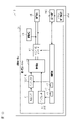
- the fuel cell unit 20 includes an auxiliary device 14 and a fuel cell system 21.
- the fuel cell system 21 includes a fuel cell 22 , a voltage sensor 23 , a current sensor 24 , a DC/DC converter 30 , a power storage device 25 , a state of charge detector 26 and a control device 40 .
- the hydrogen tank 11 stores hydrogen gas. Hydrogen gas discharged from the hydrogen tank 11 is supplied to the fuel cell 22 .
- the valve 12 is a member for adjusting the amount of hydrogen gas supplied from the hydrogen tank 11 to the fuel cell 22 .
- the valve 12 is an electromagnetically driven open/close valve in which a valve body is electromagnetically driven according to the drive cycle and/or the valve opening time. The amount of hydrogen gas supplied to the fuel cell 22 can be adjusted by controlling the drive cycle and/or valve opening time of the valve 12 .
- the compressor 13 is an electric compressor driven by an electric motor. Compressor 13 supplies air to fuel cell 22 . The amount of air supplied to the fuel cell 22 can be adjusted by controlling the rotation speed of the electric motor through control of the voltage applied to the electric motor.
- the fuel cell 22 is a fuel cell stack including multiple fuel cells connected in series with each other.
- a fuel cell is, for example, a polymer electrolyte fuel cell.
- the fuel cell 22 generates electricity through an electrochemical reaction between the fuel gas and the oxidant gas. In one example, power generation is performed using hydrogen gas as a fuel gas and oxygen in the air as an oxidant gas.
- the fuel cell 22 generates electricity using hydrogen gas supplied from the hydrogen tank 11 and oxygen supplied from the compressor 13 .
- a voltage sensor 23 measures the voltage of the fuel cell 22 .
- a measurement result of the voltage sensor 23 is acquired by the control device 40 .
- a current sensor 24 measures the current of the fuel cell 22 .
- a measurement result of the current sensor 24 is acquired by the control device 40 .
- the DC/DC converter 30 is connected to fuel cell 22 .
- the DC/DC converter 30 boosts and outputs the DC power generated by the fuel cell 22 .
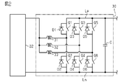
- the DC/DC converter 30 includes a positive line Lp, a negative line Ln, six switching elements Q1, Q2, Q3, Q4, Q5, Q6, six diodes D1, D2, D3, D4, D5, D6, three reactors 31, 32, 33, and a capacitor C are provided.
- the first switching element Q1 and the second switching element Q2 are connected in series with each other.
- the third switching element Q3 and the fourth switching element Q4 are connected in series with each other.
- the fifth switching element Q5 and the sixth switching element Q6 are connected in series with each other.
- the first switching element Q1, the third switching element Q3, and the fifth switching element Q5 are connected to the positive line Lp.
- the second switching element Q2, the fourth switching element Q4, and the sixth switching element Q6 are connected to the negative line Ln.
- the first switching element Q1, the third switching element Q3, and the fifth switching element Q5 form an upper arm.
- the second switching element Q2, the fourth switching element Q4, and the sixth switching element Q6 form a lower arm.
- MOSFETs Metal Oxide Semiconductor Field Effect Transistor
- IGBTs Insulated Gate Bipolar Transistors
- Each of the diodes D1-D6 is connected in parallel to the corresponding switching elements Q1-Q6.
- Each of diodes D1-D6 is a parasitic diode of corresponding switching element Q1-Q6.
- the cathodes of the diodes D1, D3, D5 connected in parallel to the switching elements Q1, Q3, Q5 forming the upper arm are connected to the positive line Lp.
- the anodes of diodes D1, D3, D5 connected in parallel to the switching elements Q1, Q3, Q5 constituting the upper arm are each connected to the middle point of the two switching elements Q1 to Q6 connected in series.
- the cathodes of diodes D2, D4 and D6 connected in parallel to the switching elements Q2, Q4 and Q6 forming the lower arm are each connected to the midpoint of the two switching elements Q1 to Q6 connected in series with each other.
- Anodes of diodes D2, D4 and D6 connected in parallel to switching elements Q2, Q4 and Q6 forming the lower arm are connected to the negative electrode line Ln.
- Reactors 31, 32 and 33 are connected one by one to the midpoints of the switching elements Q1, Q3 and Q5 forming the upper arms and the switching elements Q2, Q4 and Q6 forming the lower arms. Reactors 31 , 32 , 33 are connected to fuel cell 22 .
- the capacitor C is connected to the positive line Lp and the negative line Ln.
- the voltage is boosted by switching operations of the switching elements Q1 to Q6.
- DC/DC converter 30 outputs a DC voltage in the voltage band of power storage device 25, for example.
- the auxiliary machine 14 is connected to a DC/DC converter 30.
- the auxiliary device 14 is an electrical component included in the fuel cell unit 20 and driven by the power generated by the fuel cell 22 .
- the vehicle load 15 is connected to the DC/DC converter 30 .
- the vehicle load 15 includes an electrical component other than the auxiliary device 14 among the electrical components included in the fuel cell vehicle 10 and driven by the electric power generated by the fuel cell 22 .
- the vehicle load 15 includes a driving motor for driving the fuel cell vehicle 10, an inverter for driving the driving motor, and the like. If fuel cell vehicle 10 is an industrial vehicle, vehicle load 15 may further include a cargo handling motor and an inverter for driving the cargo handling motor. Vehicle load 15 can supply regenerated electric power generated by a motor or the like to fuel cell system 21 .
- Auxiliary machine 14 and vehicle load 15 are loads. Fuel cell 22 supplies power to a load via DC/DC converter 30 . In the following description, the auxiliary machine 14 and the vehicle load 15 are collectively referred to as loads as appropriate.
- the power storage device 25 is connected to the power line between the fuel cell 22 and the load.
- the storage device 25 is also connected in parallel with the load. Any device may be used as the power storage device 25 as long as it can be charged and discharged.
- Examples of the power storage device 25 include a secondary battery and a capacitor such as a lithium ion capacitor. In general, capacitors have relatively small capacity and excellent charging and discharging characteristics. By configuring the power storage device 25 with a capacitor, the charging/discharging characteristics of the fuel cell system 21 can be made relatively high.
- the power storage device 25 When the power generated by the fuel cell 22 exceeds the required power of the load, the power storage device 25 is charged with the surplus power. When the power generated by the fuel cell 22 is less than the required power of the load, the power storage device 25 discharges the insufficient power.
- the power generated by the fuel cell 22 can also be said to be the output power of the fuel cell 22 .
- the charging state detection unit 26 detects the charging state of the power storage device 25 .
- Examples of the state of charge include the charging rate of the power storage device 25, the remaining capacity of the power storage device 25, and the open circuit voltage of the power storage device 25.
- FIG. In one example, state-of-charge detector 26 detects the charging rate of power storage device 25 .
- the state-of-charge detector 26 includes a sensor and an estimator that estimates the state of charge from the detection result of the sensor.
- the sensors include at least one of current sensors and voltage sensors.
- the estimating unit uses a current integration method for integrating the charging/discharging current of the power storage device 25, a method using a correlation between the open circuit voltage of the power storage device 25 and the charging rate of the power storage device 25, or a combination of these methods to estimate the power storage device 25.
- the open circuit voltage may be estimated from the closed circuit voltage.
- the control device 40 includes a processor 41 and a storage unit 42.
- the processor 41 is a control unit configured by a microcomputer or the like. Examples of the processor 41 include a CPU (Central Processing Unit), a GPU (Graphics Processing Unit), and a DSP (Digital Signal Processor).
- the storage unit 42 includes RAM (Random Access Memory), ROM (Read Only Memory), and rewritable nonvolatile memory. Examples of non-volatile memory include EEPROM (Electrically Erasable Programmable Read-Only Memory) and flash memory.
- the storage unit 42 stores program code or instructions configured to cause the processor to perform processing. Storage 42, or computer-readable media, includes any available media that can be accessed by a general purpose or special purpose computer.
- the control device 40 may be configured by a hardware circuit such as an ASIC (Application Specific Integrated Circuit) or an FPGA (Field Programmable Gate Array).
- the processing circuit, the controller 40 may include one or more processors operating according to a computer program, one or more hardware circuits such as ASICs or FPGAs, or a combination thereof.
- the control device 40 controls the power generated by the fuel cell 22 .
- the power generated by the fuel cell 22 varies depending on the amount of hydrogen gas supplied to the fuel cell 22 and the amount of oxygen supplied to the fuel cell 22 .
- the control device 40 controls the amount of hydrogen gas supplied to the fuel cell 22 by controlling the valve 12 .
- the control device 40 controls the amount of oxygen supplied to the fuel cell 22 by controlling the compressor 13 .
- the control device 40 controls the DC/DC converter 30 .
- Control device 40 controls switching elements Q1-Q6 so that fuel cell 22 outputs electric power corresponding to the electric power demanded by the load.
- the voltage of the fuel cell 22 becomes lower than the voltage of the power storage device 25 while the fuel cell 22 is generating power. In one example, the voltage of fuel cell 22 is higher than the voltage of power storage device 25 when power generation by fuel cell 22 is stopped.
- the control device 40 boosts the voltage by switching the switching elements Q1 to Q6 while the fuel cell 22 is generating power.
- the control device 40 does not perform the switching operation of the switching elements Q1 to Q6 when the power generation of the fuel cell 22 is stopped.
- a current flows to power storage device 25 from diodes D1, D3 and D5, which are parasitic diodes of switching elements Q1, Q3 and Q5 forming the upper arm.
- the power storage device 25 can be charged while the voltage of the fuel cell 22 is stepped down by the diodes D1, D3, and D5.
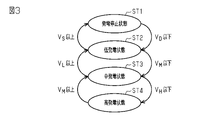
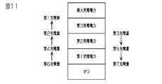
- the control device 40 switches the power generation state of the fuel cell 22 in stages according to the charging rate of the power storage device 25 .
- the power generation state of the fuel cell 22 includes a power generation stop state ST1, a low power generation state ST2, an intermediate power generation state ST3, and a high power generation state ST4.
- Power generation [kW] of the fuel cell 22 is associated with each of the power generation stop state ST1, the low power generation state ST2, the medium power generation state ST3, and the high power generation state ST4.
- the control device 40 controls the power generated by the fuel cell 22 by switching the power generation state.
- the generated power associated with the power generation state is the target value of the generated power.
- the control device 40 performs control so that the power generated by the fuel cell 22 follows the target value.
- the power generation stop state ST1 is a state in which the fuel cell 22 does not generate power.
- the generated power in the power generation stop state ST1 is 0 [kW].
- the low power generation state ST2 is a state in which the fuel cell 22 generates power.
- the power generated by the fuel cell 22 in the low power generation state ST2 is defined as the low power generation.
- the low generated power is, for example, 3 [kW].
- the low power generation state ST2 is the first power generation state.
- the low generated power is the first generated power.
- the intermediate power generation state ST3 is a state in which the power generated by the fuel cell 22 is made larger than that in the low power generation state ST2.
- the power generated by the fuel cell 22 in the middle power generation state ST3 is referred to as middle power generation.
- the medium generated power is a variable value that changes according to the usage status of the fuel cell 22 .
- the intermediate power generation state ST3 is the second power generation state.
- the intermediate generated power is the second generated power.
- the high power generation state ST4 is a state in which the fuel cell 22 is caused to generate the power required by the load when the fuel cell vehicle 10 operates at the maximum load.
- the power generated by the fuel cell 22 in the high power generation state ST4 is referred to as high power generation.
- the high generated power is, for example, 12 [kW].
- the high power generation state ST4 is the third power generation state.
- the high generated power is the third generated power.
- the control device 40 causes the fuel cell 22 to transition to the low power generation state ST2.
- the power generation start threshold VD is, for example, 50[%].
- the control device 40 causes the fuel cell 22 to transition to the intermediate power generation state ST3.
- the medium power generation switching threshold VM is, for example, 45[%].
- the control device 40 transitions the fuel cell 22 to the high power generation state ST4.
- the high power generation switching threshold VH is, for example, 30[%].
- the control device 40 causes the fuel cell 22 to transition to the medium power generation state ST3.
- the state of charge of the power storage device 25 becomes equal to or higher than the low power generation switching threshold VL while the fuel cell 22 is in the middle power generation state ST3
- the control device 40 causes the fuel cell 22 to transition to the low power generation state ST2.
- the low power generation switching threshold VL is, for example, 60[%].
- the control device 40 causes the fuel cell 22 to transition to the power generation stop state ST1.
- the power generation stop threshold VS is, for example, 70[%].
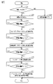
- the control device 40 performs medium power generation setting processing.
- the middle generated power setting process is a process for setting the middle generated power.
- the intermediate generated power setting process is repeatedly performed at a predetermined control cycle when the fuel cell vehicle 10 is in an activated state.
- the activated state is a state in which the fuel cell vehicle 10 can run.
- the activated state is also called a key-on state.
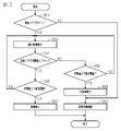
- step S1 the control device 40 determines whether the fuel cell 22 is generating power. Whether or not the fuel cell 22 is generating power can be determined from the power generation state of the fuel cell 22 . If the fuel cell 22 is in the power generation stop state ST1, the control device 40 determines that the fuel cell 22 is not generating power. The control device 40 determines that the fuel cell 22 is generating power if the fuel cell 22 is in the low power generation state ST2, the medium power generation state ST3, or the high power generation state ST4. When the determination result of step S1 is affirmative, the control device 40 performs the process of step S2. When the determination result of step S1 is negative, the control device 40 performs the process of step S6.
- step S ⁇ b>2 the control device 40 stores the value of the power generated by the fuel cell 22 in the storage section 42 . Specifically, the control device 40 calculates the power generated by the fuel cell 22 from the detection result of the current sensor 24 and the detection result of the voltage sensor 23 . Then, the control device 40 stores the generated power value in the storage unit 42 .
- the current sensor 24 and the voltage sensor 23 are generated power detection units that detect the generated power of the fuel cell 22 .
- step S3 the control device 40 determines whether or not the counter has expired.
- the control device 40 counts the number of times the process of step S2 is performed.
- the control device 40 determines that the counter has expired when the number of times the process of step S2 has been performed reaches a preset number of times. That is, the control device 40 determines that the counter has expired when the number of times the value of the power generated by the fuel cell 22 is stored in the storage unit 42 reaches a predetermined number of times. If the determination result of step S3 is negative, the control device 40 returns to the process of step S2.
- the control device 40 performs the process of step S4. It can be said that the control device 40 performs the processing of step S2 until the counter expires.
- step S4 the control device 40 calculates the power reference value [kW].
- the power reference value is a value that indicates the performance of power generation by the fuel cell 22 .
- the average power generated by the fuel cell 22 is used as the power reference value.
- the control device 40 calculates the average value of the power generated by the fuel cell 22 stored in the storage unit 42 through the processes of steps S2 and S3. Control device 40 sets this average value as the power reference value.
- the control device 40 that performs the process of step S4 functions as a power reference value calculator.
- step S5 the control device 40 updates the medium generated power.
- Control device 40 obtains the difference between the power reference value and the initial value, and divides this difference by a predetermined time [h].
- the predetermined time is also called a reference time.
- the control device 40 calculates the medium generated power by adding the value obtained by this division to the initial value. That is, the control device 40 calculates the intermediate generated power from the following equation (1).
- the initial value is a preset value when the process of step S5 is performed for the first time. When the process of step S5 is performed for the first time, it can be said that the intermediate generated power is not updated.
- the set value can be set to any value in the range between low power generation and high power generation.
- the initial value is the middle generated power value calculated in the previous control cycle when the process of step S5 is performed for the second time or later. That is, the initial value is the current value of medium generated power.
- the predetermined time is set to a value that allows calculation of medium generated power in accordance with the usage status of the load for a period of one week. For example, assuming that the fuel cell vehicle 10 operates for 8 hours per day for 5 days in a week, the predetermined time is 40 [h].
- the medium generated power as the time during which the fuel cell 22 is generating power elapses, the medium generated power asymptotically approaches the average value of the power reference values obtained during a predetermined period of time. That is, the medium generated power can be regarded as the average value of the generated power generated by the fuel cell 22 during the most recent predetermined period of time.
- the control device 40 sets the value calculated by the formula (1) as the new intermediate generated power, and terminates the intermediate generated power setting process.
- the control device 40 that performs the process of step S5 functions as an updating unit.
- the middle generated power is set between the low generated power and the high generated power. It can be said that medium power generation is greater than low power generation and less power than high power generation.
- step S6 the control device 40 sets the intermediate generated power to the previous value. That is, the control device 40 maintains the intermediate generated power calculated in the previous control cycle. Note that the value of the intermediate generated power is stored in the non-volatile memory of the storage unit 42 so that it is retained even when the fuel cell vehicle 10 is in the key-off state.
- the usage status of the fuel cell 22 changes according to the usage status of the fuel cell vehicle 10 .
- the usage of the fuel cell 22 differs from customer to customer.
- the usage status of the fuel cell 22 varies depending on factors such as the difference in the operation method of the fuel cell vehicle 10 by the operator of the fuel cell vehicle 10, the environment in which the fuel cell vehicle 10 is used, the presence or absence of a busy season, and the time of the busy season. different.
- the appropriate middle power generation is different for each customer.
- Appropriate intermediate power generation is power that reduces transitions from the intermediate power generation state ST3 to a power generation state different from the intermediate power generation state ST3.
- the medium power generation is updated based on the power reference value that indicates the power generation performance of the fuel cell 22 .
- the intermediate generated power is set according to the usage status of the fuel cell 22 . Insufficient or excessive power generated by the fuel cell 22 can be suppressed.
- the medium generated power is a constant value of 5 [kW] and the load requires 4 [kW] of power on average
- the power storage device 25 is charged with 1 [kW] of power. As the charging rate of the power storage device 25 increases, the intermediate power generation state ST3 transitions to the low power generation state ST2.
- the medium generated power is a constant value of 5 [kW] and the load requires 6 [kW] of power on average
- 1 [kW] of power is discharged from the power storage device 25 .
- the intermediate power generation state ST3 transitions to the high power generation state ST4.
- charging and discharging of the power storage device 25 can be suppressed compared to the case where the intermediate generated power is set to a constant value. Since the power generation state of the fuel cell 22 transitions in accordance with the state of charge of the power storage device 25, reducing fluctuations in the state of charge of the power storage device 25 can reduce the number of times the power generation state transitions.
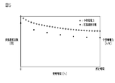
- FIG. 5 shows an example of the relationship between the power generation time during which the fuel cell 22 generated power, the number of times the power generation state of the fuel cell 22 transitioned, and the medium generated power.
- the time when the initial value of equation (1) is the set value, that is, the time when the actual power generation performance of the fuel cell 22 is not reflected in the medium generated power is set to 0.
- the medium generated power is updated every time the fuel cell 22 generates power. Every time the fuel cell 22 has generated power, the actual power generation performance of the fuel cell 22 is accumulated, and the middle generated power is set reflecting the tendency of the usage of the load. After a predetermined period of time has elapsed, the medium generated power is set, which fully reflects the usage of the load. As the intermediate generated power is updated, the number of times the power generation state of the fuel cell 22 transitions also decreases.
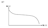
- the fuel cell 22 has a characteristic that the higher the generated power, the higher the current, and the higher the generated power, the lower the voltage.
- the theoretical voltage of the fuel cell 22 is 1.23 [V], and the loss of the fuel cell 22 increases as the voltage of the fuel cell 22 deviates from the theoretical voltage.
- the theoretical voltage is the voltage obtained when all the chemical energy of hydrogen gas can be converted into electrical energy.
- the medium generated power gradually decreases. In this way, by setting the medium generated power based on the actual power generation performance of the fuel cell 22, it is possible to prevent the generated power of the fuel cell 22 from becoming excessively high. Thereby, the loss of the fuel cell 22 can be reduced.
- the control device 40 obtains the difference between the power reference value and the initial value, and divides this difference by a predetermined time.
- the control device 40 calculates a new intermediate generated power by adding the value thus obtained to the initial value.
- the middle generated power gradually decreases or increases according to the power generation performance of the fuel cell 22 . Even if the generated power of the fuel cell 22 temporarily becomes excessively large or temporarily becomes excessively small, the medium generated power is calculated according to the performance of power generation while suppressing the influence of this. be able to.
- the storage unit 42 compared to the case where the power generated by the fuel cell 22 obtained during a predetermined period of time is stored in the storage unit 42 and the average value of the generated power obtained during the predetermined period of time is calculated as the middle generated power, the storage unit The amount of data stored in the unit 42 is reduced. Therefore, it is possible to suppress an increase in the capacity of the storage unit 42 .
- the power generation state of the fuel cell 22 is less likely to transition from the intermediate power generation state ST3, the power generated by the fuel cell 22 is less likely to fluctuate.
- the driving force of the compressor 13 and the driving cycle and/or valve opening time of the valve 12 change, which causes the quietness of the fuel cell vehicle 10 to deteriorate.
- the quietness of the fuel cell vehicle 10 can be improved.
- the control apparatus 40 may control the value of low electric power generation as a fluctuation value.
- the value of low generated power is changed according to the value of medium generated power.
- the control device 40 may control the value of the low generated power to be half the value of the medium generated power.
- control device 40 may set a lower limit value and an upper limit value for the value of the low generated power, and vary the value of the low generated power within a range between the lower limit value and the upper limit value.
- the values of the lower limit and upper limit are arbitrary.
- the lower limit value may be, for example, the lower limit of the voltage conversion limit value.
- the upper limit value may be, for example, the upper limit of the voltage conversion limit value.
- the upper limit of the voltage conversion limit value is the power generated when the voltage of the fuel cell 22 reaches the minimum voltage that can be input to the DC/DC converter 30.
- the DC/DC converter 30 has an allowable range of input voltage. By setting the upper limit of the voltage conversion limit value as described above, it is possible to prevent the voltage input to DC/DC converter 30 from falling below the lower limit value of the allowable range.
- the lower limit of the voltage conversion limit value is the voltage at which the voltage of the fuel cell 22 matches the voltage of the power storage device 25 .
- the voltage is stepped down using diodes D1, D3, and D5.
- the voltage is stepped down using the diodes D1, D3, and D5, loss occurs due to this stepping down.
- the control device 40 may set a lower limit value and an upper limit value for the medium generated power value.
- the lower limit value of the medium generated power and the upper limit value of the medium generated power can be set arbitrarily.
- the lower limit of the voltage conversion limit value may be used as the lower limit value of the medium generated power, and the upper limit of the voltage conversion limit value may be used as the upper limit value of the voltage conversion limit value.
- Medium generated power may be a value corresponding to the power standard value, and may be calculated by a method different from formula (1).
- the middle generated power may be a moving average of the generated power over a predetermined period of time.
- the control device 40 acquires the power reference value at a predetermined cycle and stores it in the storage unit 42 .
- the control device 40 divides the total sum of the power reference values obtained during the predetermined period of time by the number of times the power reference value is obtained.
- the control device 40 may set the value thus obtained as the intermediate generated power.
- the power reference value may be the median value of the power generated by the fuel cell 22 stored in the storage unit 42 through the processing of steps S2 and S3.
- the control device 40 may acquire the generated power of the fuel cell 22 only once in one control cycle, and use this generated power as the power reference value.
- the power reference value may be a moving average of generated power obtained during a predetermined period of time. In other words, the power reference value may be any value as long as it indicates the actual power generation performance of the fuel cell 22 .
- the power generation state should include three states with different generated power.
- the low power generation state ST2 of the first embodiment may be omitted, and the power generation state may transition between three states: the power generation stop state ST1, the middle power generation state ST3, and the high power generation state ST4.
- the power generation stop state ST1 is the first power generation state
- the intermediate power generation state ST3 is the second power generation state
- the high power generation state ST4 is the third power generation state.
- the power generation state may include five or more states with different generated power.
- the state corresponding to the average value of the power generated by the fuel cell 22 is the second power generation state.
- a state in which the generated power is one step lower than the second power generation state is the first power generation state.
- a state in which the generated power is one step higher than the second power generation state is the third power generation state.
- the power generated by the fuel cell 22 may be calculated by dividing the power supplied to the vehicle load 15 by the value of "1-Auxiliary loss ratio".
- the current sensor 24 and the voltage sensor 23 are provided so that the power supplied to the vehicle load 15 can be measured.
- Auxiliary equipment loss includes loss caused by DC/DC converter 30 and power consumed by auxiliary equipment 14 .
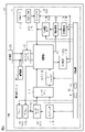
- FIG. 6 is a diagram showing an example of the fuel cell system 21 of the second embodiment.
- a fuel cell system 21 shown in FIG. 6 is mounted in a fuel cell vehicle 10 such as an industrial vehicle such as a forklift or an automobile, and supplies electric power to a vehicle load 15 and the like.
- the fuel cell system 21 includes a fuel cell 22, a hydrogen tank 11, a hydrogen tank valve 101, an injector 102, a gas-liquid separator 103, a hydrogen circulation pump 104, an exhaust/drain valve 105, and a compressor 13. , an air pressure regulating valve 106 , an air shutoff valve 107 , a radiator 108 , a fan 109 , a water pump 110 , an intercooler 111 , a DC/DC converter 30 , a power storage device 25 , and a control device 40 .
- the hydrogen tank valve 101, the injector 102, the hydrogen circulation pump 104, the exhaust/drain valve 105, the compressor 13, the air pressure regulating valve 106, the air shut valve 107, the fan 109, and the water pump 110 are fed from the fuel cell 22, in other words DC/DC. It is the accessory 14 that consumes the power supplied from the converter 30 . As the rotational speed of the motors for driving the hydrogen circulation pump 104, the compressor 13, the fan 109, and the water pump 110 increases, the amount of power supplied from the fuel cell 22 increases. Auxiliary equipment 14 such as compressor 13 and injector 102 is a first auxiliary equipment directly involved in power generation of fuel cell 22 .
- Auxiliary equipment 14 such as hydrogen circulation pump 104 , fan 109 , and water pump 110 are second auxiliary equipment that are not directly involved in the power generation of fuel cell 22 . That is, the first auxiliary equipment directly related to the power generation of the fuel cell 22 can be rephrased as an auxiliary equipment for supplying the reaction gas (fuel gas and oxidant gas) to the fuel cell 22 . A second auxiliary device that is not directly involved in the power generation of the fuel cell 22 can be rephrased as an auxiliary device that does not supply the reaction gas to the fuel cell 22 .
- Fuel gas stored in the hydrogen tank 11 is supplied to the fuel cell 22 via the hydrogen tank valve 101 and the injector 102 .
- the hydrogen tank valve 101 reduces the pressure of the fuel gas supplied to the fuel cell 22 .
- the injector 102 adjusts the flow rate of fuel gas supplied to the fuel cell 22 .
- the gas-liquid separator 103 separates the fuel gas and liquid water discharged from the fuel cell 22 .
- the hydrogen circulation pump 104 resupplies the fuel gas separated by the gas-liquid separator 103 to the fuel cell 22 .
- the exhaust and drain valve 105 discharges the liquid water separated by the gas-liquid separator 103 to the outside.
- Compressor 13 compresses the oxidant gas and supplies it to fuel cell 22 via intercooler 111 and air shut valve 107 .
- the intercooler 111 exchanges heat between the oxidant gas and a refrigerant such as cooling water flowing through the intercooler 111 .
- the air shut valve 107 cuts off the oxidant gas supplied to the fuel cell 22 .
- the air pressure regulating valve 106 regulates the pressure and/or flow rate of the oxidant gas supplied to the fuel cell 22 .
- the radiator 108 heat-exchanges the coolant warmed by the heat generated by the fuel cell 22 with the outside air.
- the fan 109 increases the heat dissipation amount of the radiator 108.
- the fuel cell system 21 has a bypass channel 112 that connects the input and output of the radiator 108 .
- the coolant output from the fuel cell 22 can be supplied to the water pump 110 through the bypass passage 112 without passing through the radiator 108 . Therefore, even if the rotation speed of the motor for driving the fan 109 is increased to increase the heat radiation amount of the radiator 108, it is possible to prevent the refrigerant from being overcooled.
- Water pump 110 supplies coolant cooled by radiator 108 to fuel cell 22 via intercooler 111 .
- the DC/DC converter 30 is provided after the fuel cell 22 and supplies power output from the fuel cell 22 to the power storage device 25 .
- electric power remaining after excluding electric power consumed by auxiliary machine 14 can be supplied to power storage device 25 .
- the power storage device 25 is provided between the DC/DC converter 30 and the loads 14 and 15 . Power storage device 25 is connected to power lines between fuel cell 22 and loads 14 and 15 . Power storage device 25 is also connected in parallel with loads 14 and 15 . The power storage device 25 supplies electric power to the vehicle load 15 and the auxiliary machines 14 such as the hydrogen circulation pump 104 , the compressor 13 , the fan 109 and the water pump 110 .
- the controller 40 controls the hydrogen tank valve 101, the injector 102, the hydrogen circulation pump 104, the exhaust/drain valve 105, the compressor 13, and the air conditioner so that the power generated in the fuel cell 22 reaches the target power Pt.
- Various accessories 14 such as the pressure valve 106, the air shut valve 107, the fan 109, and the water pump 110 are driven.
- the control device 40 turns on the power of the motors for driving the various auxiliary devices 14, and then outputs a command value indicating the target rotation speed of each motor.
- control device 40 changes the target power Pt according to the amount of charge (state of charge) of the power storage device 25 during normal power generation control.
- the amount of charge is, for example, the charging rate [%], which is the ratio of the remaining capacity to the fully charged capacity of the power storage device 25, or the voltage [V] of the power storage device 25 when no current is flowing through the power storage device 25. be.
- control device 40 may be configured to change the target electric power Pt step by step according to the amount of charge in the power storage device 25 .
- a plurality of stages of charging rates having a relationship of "charging rate SOC1 ⁇ charging rate SOC2 ⁇ charging rate SOC3 ⁇ charging rate SOC4 ⁇ charging rate SOC5 ⁇ charging rate SOC6" and a relationship of "target power Pt1 ⁇ target power Pt2". Two levels of target power Pt are defined.
- control device 40 sets target electric power Pt1 as target electric power Pt when the state of charge of power storage device 25 decreases within the range of state of charge SOC3 to state of charge SOC5.
- Control device 40 sets target electric power Pt2 as target electric power Pt when the state of charge of power storage device 25 decreases within the range of state of charge SOC1 to state of charge SOC3.
- control device 40 sets target power Pt2 as target power Pt.
- control device 40 sets target power Pt1 as target power Pt.
- FIG. 7 shows an example of the relationship between the current and voltage output from the fuel cell 22 in two-dimensional coordinates.
- the horizontal axis indicates current [A] and the vertical axis indicates voltage [V].
- a solid line indicates the correspondence between the current and voltage output from the fuel cell 22 .
- the voltage output from the fuel cell 22 increases as the current output from the fuel cell 22 decreases.
- the catalyst necessary for the electrochemical reaction is ionized.
- the crystals of the ionized catalyst grow larger.
- the particle size of the catalyst increases and the total surface area of the catalyst decreases, which may deteriorate the fuel cell 22 .
- the control device 40 forcibly drives the DC/DC converter 30 when the output voltage of the fuel cell 22 becomes equal to or higher than a predetermined voltage (determination voltage) Vc, so that the DC from the fuel cell 22 is The current flowing through the /DC converter 30 is increased to decrease the voltage output from the fuel cell 22 .
- the voltage output from the fuel cell 22 is relatively high during idling when the fuel cell vehicle 10 is temporarily stopped such as when waiting for a signal and the current flowing from the fuel cell system 21 to the vehicle load 15 is relatively small. can be suppressed. Therefore, deterioration of the fuel cell 22 can be suppressed.
- the regenerative electric power supplied from the fuel cell vehicle 10 that is, the vehicle load 15
- the accelerator of the fuel cell vehicle 10 is operated by the driver so that the speed of the fuel cell vehicle 10 becomes constant, thereby accelerating the fuel cell vehicle 10. becomes relatively small.
- the controller 40 controls the control device 40 when the regenerated power supplied from the fuel cell vehicle 10 to the fuel cell system 21 is equal to or higher than a predetermined power (determination voltage) and the acceleration of the fuel cell vehicle 10 is When the acceleration is equal to or less than a predetermined acceleration (determined acceleration), that is, when there is a high possibility that the fuel cell vehicle 10 is running downhill and the power storage device 25 is likely to be overcharged, the power generation of the fuel cell 22 is stopped. While the engine is stopped, the second auxiliary machine, which is not directly related to the power generation of the fuel cell 22, is forcibly driven so that the output voltage of the fuel cell 22 does not become relatively high.
- control device 40 multiplies the voltage output from the fuel cell vehicle 10 to the fuel cell system 21 by the current flowing from the fuel cell vehicle 10 to the fuel cell system 21, and outputs the result from the fuel cell vehicle 10 to the fuel cell system 21. It is calculated as regenerative power supplied to The control device 40 also receives the speed [km/h] of the fuel cell vehicle 10 from a travel control unit (not shown) mounted on the fuel cell vehicle 10, and calculates the amount of change in the speed of the fuel cell vehicle 10 per unit time. is obtained as the acceleration of the fuel cell vehicle 10 .
- the speed of the fuel cell vehicle 10 can be obtained, for example, from "(rotational speed of travel motor x outer diameter of tire x circumference ratio)/(gear ratio x reduction ratio)".
- the control device 40 receives the acceleration of the fuel cell vehicle 10 obtained by the acceleration sensor from the travel control section.
- the control device 40 stops the power generation of the fuel cell 22, A second auxiliary device that is not directly involved in the power generation of the fuel cell 22 is driven.
- the second auxiliary device so that the power storage device 25 is not overcharged
- the control device 40 continues normal power generation control.
- control device 40 increments the counter value when the regenerated electric power is equal to or greater than the predetermined electric power and the acceleration of the fuel cell vehicle 10 is equal to or less than the predetermined acceleration.
- Control device 40 decrements the counter value when the regenerated electric power is less than a predetermined electric power or when the acceleration of fuel cell vehicle 10 is greater than a predetermined acceleration.
- the control device 40 determines that the fuel cell vehicle 10 is running downhill, and sets the downhill flag to ON.
- the control device 40 stops the power generation of the fuel cell 22 and drives the second auxiliary machine that is not directly related to the power generation of the fuel cell 22 .
- the control device 40 stops the power generation of the fuel cell 22 and activates the second auxiliary device that is not directly related to the power generation of the fuel cell 22. drive.
- the control device 40 may be configured to prepare to drive a second auxiliary device that is not directly related to the power generation of the fuel cell 22 when the counter value reaches or exceeds a threshold C2th (second threshold) that is smaller than the threshold C1th. good.
- the second accessory can be activated immediately after the counter value reaches or exceeds the threshold C1th.
- the electric power supplied from the fuel cell 22 by being driven can be consumed by the second auxiliary machine. Therefore, it is possible to further prevent power storage device 25 from being overcharged.
- control device 40 stops the power generation of the fuel cell 22 and then controls the power generation of the plurality of second auxiliary units.
- one or more second auxiliary machines corresponding to the amount of charge in power storage device 25 may be driven.
- control device 40 may be configured to drive a number of second accessories corresponding to the amount of charge in power storage device 25 .
- control device 40 is configured to select one or more second auxiliaries to be driven from among a plurality of second auxiliaries having different power consumptions, according to the amount of charge in power storage device 25. good too.
- control device 40 performs any one of the following operation controls 1) to 4) as the operation control of the auxiliary machine.
- the rotation speed of the motor for driving the water pump 110 is set to the maximum rotation speed.
- the rotation speed of the motor for driving the water pump 110 and the hydrogen circulation pump 104 is set to the maximum rotation speed.
- the rotation speeds of the motors for driving the water pump 110, the hydrogen circulation pump 104, and the fan 109 are set to the maximum rotation speed.
- the rotation speed of the motors for driving the water pump 110, the hydrogen circulation pump 104, and the fan 109 is set to the maximum rotation speed, the rotation speed of the motor for driving the compressor 13 is increased, and the electric potential is high.
- a predetermined voltage Vc for avoidance is increased.
- threshold values are set in a plurality of stages having a relationship of “threshold value S1th ⁇ threshold value S2th ⁇ threshold value S3th ⁇ threshold value S4th”.
- the control device 40 stops the power generation of the fuel cell 22 when the regenerated electric power is equal to or greater than the predetermined electric power and the acceleration of the fuel cell vehicle 10 is equal to or less than the predetermined acceleration. Then, when the amount of charge in the power storage device 25 is equal to or greater than the threshold value S1th, the control device 40 performs the above operation control of 1), and when the charge amount of the power storage device 25 is equal to or greater than the threshold value S2th, the control device 40 performs the above operation control of 2).
- the operation control of 3 When the charge amount of the power storage device 25 is equal to or greater than the threshold value S3th, the operation control of 3) is performed, and when the charge amount of the power storage device 25 is equal to or greater than the threshold value S4th, the operation control of 4) is performed.
- the control device 40 When the power generation of the fuel cell 22 is stopped, if the charge amount of the power storage device 25 is equal to or greater than the threshold value S1th, the control device 40 performs the operation control of 1) above. Therefore, the power of the power storage device 25 can be consumed while minimizing the influence of deterioration of the fuel cell 22 .
- the control device 40 When the power generation of the fuel cell 22 is stopped and the charge amount of the power storage device 25 is equal to or greater than the threshold value S2th, the control device 40 performs the operation control of 2) above. Therefore, the power of the power storage device 25 can be consumed while the influence of deterioration of the fuel cell 22 is relatively low.
- the control device 40 When the power generation of the fuel cell 22 is stopped and the charge amount of the power storage device 25 is equal to or greater than the threshold value S3th, the control device 40 performs the operation control of 3) above. Therefore, the influence of deterioration of the fuel cell 22 can be suppressed while the power consumption of the power storage device 25 is relatively increased.
- the control device 40 performs the operation control of 4) above. Therefore, the degree of influence of deterioration of the fuel cell 22 can be suppressed while maximizing the power consumption of the power storage device 25 .
- FIG. 8 is a flowchart showing an example of the operation of the control device 40 during downhill flag switching processing. Note that the processing shown in FIG. 8 is repeatedly executed at predetermined timings or at constant intervals.
- step S11: Yes when the regenerated power supplied from the fuel cell vehicle 10 to the fuel cell system 21 is greater than or equal to the predetermined power and the acceleration of the fuel cell vehicle 10 is less than or equal to the predetermined acceleration (step S11: Yes), the counter value of the counter is incremented (step S12).
- step S13: Yes when the counter value is equal to or greater than the threshold value C2th (second threshold value) (step S13: Yes), the control device 40 prepares to drive various accessories (step S14).
- step S15: Yes when the counter value is equal to or greater than the threshold value C1th (first threshold value) (step S15: Yes), the control device 40 sets the counter value to the same value as the threshold value C1th, and turns on the downhill flag (step S16). , the descending slope flag switching process is terminated.
- step S17 if the regenerated electric power supplied from the fuel cell vehicle 10 to the fuel cell system 21 is smaller than the predetermined electric power, or if the acceleration of the fuel cell vehicle 10 is greater than the predetermined acceleration (step S11: No), the control device 40 The counter value of the counter is decremented (step S17).
- step S18 when the counter value is equal to or less than zero (step S18: Yes), the control device 40 sets the counter value to zero and turns off the descending slope flag (step S19), ending the descending slope flag switching process.
- control device 40 if the counter value is smaller than the threshold C2th (step S13: No), or if the counter value is smaller than the threshold C1th (step S15: No), or if the counter value is greater than zero (step S18: No), the descending slope flag switching process is terminated.
- FIG. 9 is a flowchart showing an example of the operation of the control device 40 during power generation control processing.
- step S21: No when the downhill flag is off (step S21: No), the control device 40 performs normal power generation control (step S22).
- step S21: Yes when the downhill flag is ON (step S21: Yes), the control device 40 stops the power generation of the fuel cell 22 (step S23).
- step S24: Yes when the amount of charge in power storage device 25 reaches or exceeds threshold S1th (step S24: Yes), control device 40 sets the command value so that the rotation speed of the motor for driving water pump 110 reaches the maximum rotation speed. Output (step S25).
- step S26 when the amount of charge in the power storage device 25 reaches or exceeds the threshold value S2th (step S26: Yes), the controller 40 controls the command value so that the rotation speed of the motor for driving the hydrogen circulation pump 104 reaches the maximum rotation speed. is output (step S27). In step S27, control device 40 continues to output a command value for increasing the rotational speed of the motor for driving water pump 110 to the maximum rotational speed.
- step S28 when the charge amount of the power storage device 25 reaches or exceeds the threshold value S3th (step S28: Yes), the control device 40 sets the command value so that the rotation speed of the motor for driving the fan 109 reaches the maximum rotation speed. (Step S29). In step S29, the control device 40 continues to output command values for increasing the rotational speeds of the motors for driving the water pump 110 and the hydrogen circulation pump 104 to their maximum rotational speeds.
- step S30 Yes
- the control device 40 increases the rotation speed of the motor for driving the compressor 13 and increases the predetermined voltage Vc for avoiding high potential. Increase (step S31).
- step S31 the control device 40 continues to output command values for increasing the rotational speeds of the motors for driving the water pump 110, the hydrogen circulation pump 104, and the fan 109 to their maximum rotational speeds.
- FIG. 10 is a diagram showing an example of the fuel cell vehicle 10 of the third embodiment.
- a fuel cell vehicle 10 shown in FIG. 10 is a vehicle such as an industrial vehicle such as a forklift or an automobile, and includes a vehicle load 15 , a fuel cell system 21 , an accelerator operation amount detection section 202 and a travel control section 203 .
- the fuel cell system 21 includes a fuel cell 22, a hydrogen tank 11, an injector 102, a compressor 13, a DC/DC converter 30, a power storage device 25, and a control device 40. Note that the fuel cell system 21 is not limited to the configuration shown in FIG.
- Fuel gas stored in the hydrogen tank 11 is supplied to the fuel cell 22 via the injector 102 .
- the injector 102 adjusts the flow rate of fuel gas supplied to the fuel cell 22 .
- the compressor 13 compresses the oxidant gas and supplies it to the fuel cell 22 .
- the DC/DC converter 30 is provided after the fuel cell 22 and supplies power output from the fuel cell 22 to the power storage device 25 . Of the power output from DC/DC converter 30 , remaining power excluding power consumed by auxiliary equipment 14 such as compressor 13 can be supplied to power storage device 25 .
- the power storage device 25 is provided between the DC/DC converter 30 and the loads 14 and 15 . Power storage device 25 is connected to power lines between fuel cell 22 and loads 14 and 15 . Power storage device 25 is also connected in parallel with loads 14 and 15 . The power storage device 25 supplies electric power to the vehicle load 15 and the auxiliary equipment 14 such as the compressor 13 .
- the storage unit 42 of the control device 40 stores a predetermined required electric power, a predetermined speed, a predetermined accelerator operation amount, a predetermined acceleration, and the like, which will be described later.
- the predetermined required electric power, the predetermined speed, the predetermined accelerator operation amount, and the predetermined acceleration are also referred to as the determined requested electric power, the determined speed, the determined accelerator operation amount, and the determined acceleration, respectively.
- the controller 40 controls the operations of the injector 102, the compressor 13, etc. so that the power generated by the fuel cell 22 reaches the target power Pt. Further, the control device 40 changes the target power Pt according to the amount of charge (state of charge) of the power storage device 25 during normal power generation control.
- the amount of charge is, for example, a charging rate [%] that is the ratio of the remaining capacity to the full charge capacity of the power storage device 25, or an open circuit voltage [V ].
- control device 40 may be configured to change target electric power Pt in a stepwise manner according to the amount of charge in power storage device 25 .
- FIG. 11 is a diagram for explaining power generation control of the fuel cell 22. As shown in FIG. A plurality of stages of charge amounts having a relationship of "first charge amount ⁇ second charge amount ⁇ third charge amount ⁇ fourth charge amount ⁇ fifth charge amount ⁇ sixth charge amount ⁇ seventh charge amount" are defined. In addition, a plurality of stages of generated power are defined as “first generated power ⁇ second generated power ⁇ third generated power ⁇ maximum generated power”. The difference between the first generated power and the second generated power, the difference between the second generated power and the third generated power, and the difference between the third generated power and the maximum generated power may be constant values or arbitrary values. .
- the control device 40 changes the target power Pt from zero to the first generated power when the charge amount of the power storage device 25 becomes smaller than the sixth charge amount.
- control device 40 changes target power Pt from the first generated power to the second generated power.
- control device 40 changes target power Pt from the second generated power to the third generated power.
- control device 40 changes target power Pt from the third generated power to the maximum generated power.
- control device 40 changes target power Pt from the maximum generated power or the third generated power to the second generated power.
- control device 40 changes target power Pt from the second generated power to the first generated power.
- control device 40 changes target power Pt from the first generated power to zero.
- the accelerator operation amount detection unit 202 shown in FIG. 10 is composed of a potentiometer or the like connected to the accelerator pedal.
- the accelerator operation amount detection unit 202 detects an accelerator operation amount O, which is the operation amount of the accelerator pedal by the driver, and sends the detected accelerator operation amount O to the travel control unit 203 .
- the travel control unit 203 is configured by a microcomputer or the like. Travel control unit 203 may have the same configuration as control device 40 .
- the travel control unit 203 controls the travel and cargo handling of the fuel cell vehicle 10 by controlling the operation of the vehicle load 15 .
- the traveling control unit 203 obtains the required electric power Pr (the electric power required to drive the vehicle load 15) to be requested from the power storage device 25.
- the traveling control unit 203 calculates the multiplication value of the output voltage of the power storage device 25 and the current flowing from the power storage device 25 to the vehicle load 15, or the power consumption of the vehicle load 15 expected from the operation control of the vehicle load 15, It is obtained as the required power Pr.
- the travel control unit 203 obtains the speed V [m/s] and the acceleration A [m/s2] of the fuel cell vehicle 10 .
- the travel control unit 203 obtains the speed V from the calculation result of "(travel motor rotation speed [rpm] x tire outer diameter [m] x circumference ratio)/(gear ratio x reduction gear ratio)".
- the travel control unit 203 obtains the acceleration A from the amount of change in the velocity V per second.
- the travel control unit 203 may be configured to obtain the acceleration A based on the output values of an acceleration sensor mounted on the fuel cell vehicle 10 and a torque sensor connected to a travel motor.
- the traveling control unit 203 determines whether the fuel cell vehicle 10 is traveling uphill based on the required electric power Pr, the speed V, the accelerator operation amount O, and the acceleration A. It is determined whether the slope with
- the greater the slope [%] of an uphill the greater the power consumed by the driving motor.
- the weight of the fuel cell vehicle 10 is relatively large. Therefore, the power consumed by the driving motor tends to increase as the slope of the uphill slope increases. Further, the speed of the fuel cell vehicle 10 tends to decrease as the slope of the uphill increases.
- the speed of the fuel cell vehicle 10 is lower than when traveling on a flat road, so the driver tries to maintain the same speed as the flat road. Because of this psychology, the amount of operation of the accelerator pedal tends to be relatively large.
- the speed of the fuel cell vehicle 10 tends to be constant, so the acceleration of the fuel cell vehicle 10 tends to be relatively small. That is, when the fuel cell vehicle 10 is running uphill, the required electric power Pr and the accelerator operation amount O become relatively large, and the speed V and the acceleration A become relatively small.
- the travel control unit 203 determines that the required power Pr is equal to or greater than a predetermined required power, the speed V is equal to or less than a predetermined speed, the accelerator operation amount O is equal to or greater than a predetermined accelerator operation amount, and the acceleration A is If the acceleration is equal to or less than the predetermined acceleration, it is determined that the fuel cell vehicle 10 is traveling uphill. Further, the traveling control unit 203 is controlled when the required electric power Pr is smaller than the predetermined required electric power, or when the speed V is larger than the predetermined speed, or when the accelerator operation amount O is smaller than the predetermined accelerator operation amount, or the acceleration A is If the acceleration is greater than the predetermined acceleration, it is determined that the fuel cell vehicle 10 is not traveling uphill.
- the predetermined accelerator operation amount is not limited to 100% (maximum accelerator operation amount), and is experimentally and empirically determined as an operation amount that is estimated to actually be taken by the driver when traveling uphill. set on top of
- the traveling control unit 203 determines that the fuel cell vehicle 10 is traveling uphill, it notifies the control device 40 of the fuel cell system 21 of this fact by means of an uphill flag. generated power.
- FIG. 12 is a flowchart showing an example of the operation of the travel control unit 203 during the uphill flag switching process. Note that the uphill flag switching process shown in FIG. 12 is repeatedly executed at predetermined timings or at predetermined intervals.
- the travel control unit 203 determines that the required electric power Pr is equal to or greater than a predetermined required electric power, the speed V is equal to or less than a predetermined speed, the accelerator operation amount O is equal to or greater than a predetermined accelerator operation amount, and the acceleration A is If the acceleration is less than or equal to the predetermined acceleration (step S41: Yes), the counter value of the counter is incremented (step S42).
- the traveling control unit 203 sets the counter value to the same value as the threshold value, turns on the climbing flag (step S44), and starts the climbing flag switching process. finish.
- the travel control unit 203 may determine that the fuel cell vehicle 10 is traveling uphill when the uphill flag is turned on. As a result, frequent determination that the fuel cell vehicle 10 is running uphill due to fluctuations in the required electric power Pr, the speed V, the accelerator operation amount O, or the acceleration A can be suppressed. If it is frequently determined that the fuel cell vehicle 10 is running uphill, this affects the running of the fuel cell vehicle 10 and makes the driver of the fuel cell vehicle 10 feel uncomfortable. By suppressing such frequent judgments, it is possible to suppress the driver from feeling uncomfortable with the running of fuel cell vehicle 10 .
- the travel control unit 203 determines when the required electric power Pr is smaller than a predetermined required electric power, or when the speed V is larger than a predetermined speed, or when the accelerator operation amount O is smaller than a predetermined accelerator operation amount, or the acceleration A is If the acceleration is greater than the predetermined acceleration (step S41: No), the counter value of the counter is decremented (step S45).
- step S46 the travel control unit 203 sets the counter value to zero and turns off the climbing flag (step S47), ending the climbing flag switching process.
- the travel control unit 203 may determine that the fuel cell vehicle 10 is not traveling uphill when the uphill flag is turned off. As a result, frequent determination that the fuel cell vehicle 10 is not traveling uphill due to fluctuations in the required electric power Pr, the speed V, the accelerator operation amount O, or the acceleration A can be suppressed. If it is frequently determined that the fuel cell vehicle 10 is not running uphill, this affects the running of the fuel cell vehicle 10 and makes the driver of the fuel cell vehicle 10 feel uncomfortable. By suppressing such frequent judgments, it is possible to suppress the driver from feeling uncomfortable with the running of fuel cell vehicle 10 .
- step S43: No when the counter value is smaller than the threshold value (step S43: No) or when the counter value is greater than zero (step S46: No), the running control unit 203 ends the uphill flag switching process.
- FIG. 13 is a flow chart showing an example of the operation of the control device 40.
- the control device 40 performs normal power generation control (step S52). For example, as normal power generation control, the control device 40 switches the target power step by step according to the amount of charge in the power storage device 25 as shown in FIG. 11 .
- the control device 40 sets the target power to the maximum generated power (step S53).
- the controller 40 may be configured to gradually increase the power generated by the fuel cell 22 to the maximum power when increasing the power generated by the fuel cell 22 to the maximum power. Specifically, when increasing the target power Pt from the current generated power, an upper limit value may be set for the amount of change in the generated power. As a result, it is possible to suppress a sharp increase in the electric power applied from the fuel cell 22 to the auxiliary device 14 .
- step S54 Yes
- step S55 the control device 40 continues the target electric power. and set to the maximum generated power
- step S53 If the uphill flag is switched from ON to OFF (step S54: No), but the amount of charge in power storage device 25 is smaller than the lower limit of charge (step S56: No), control device 40 continues the target electric power. is set to the maximum generated power (step S53). For example, assume that the upper limit charge amount is the seventh charge amount shown in FIG. 11 and the lower limit charge amount is the third charge amount shown in FIG.
- step S54 Yes
- step S55 No
- the control device 40 sets the target electric power.
- step S53 the maximum generated power
- step S53 the control device 40 also continues the target electric power if the climbing flag has been switched from the ON state to the OFF state (step S54: No), but the charge amount of the power storage device 25 is smaller than the third charge amount (step S56: No). and set to the maximum generated power (step S53).
- step S54 when the climbing flag is continuously on (step S54: Yes), the control device 40 sets the target electric power to zero when the charge amount of the power storage device 25 becomes equal to or greater than the upper limit charge amount (step S55: Yes). to stop the power generation of the fuel cell 22 (step S57).
- step S54: No when the charge amount of the power storage device 25 becomes equal to or higher than the lower limit charge amount (step S56: Yes), the control device 40 reduces the target electric power to medium.
- the generated power is set (step S58), and then the control shifts to normal power generation control (step S52).
- the medium generated power is the second generated power shown in FIG.
- step S54: No when the charge amount of the power storage device 25 becomes equal to or higher than the lower limit charge amount (step S56: Yes), the control device 40 sets the target electric power.
- the power generation is set to the second power generation (step S58), and then the control shifts to normal power generation control (step S52).
- the target power is set to medium generated power. Therefore, it is possible to easily shift from the generated power control at the time of judgment of climbing to the normal generated power control.
- the travel control unit 203 uses the required electric power Pr, the speed V, the accelerator operation amount O, and the acceleration A to determine that the fuel cell vehicle 10 is traveling uphill. , to increase the generated power of the fuel cell 22 from the current generated power. As a result, it is not necessary to wait for the state in which the current flowing from the fuel cell system 21 to the vehicle load 15 is equal to or greater than the predetermined current to continue for a predetermined period of time. Therefore, even when the remaining capacity of the power storage device 25 is relatively small, the remaining capacity of the power storage device 25 can be rapidly increased, so that the overdischarge state of the power storage device 25 can be suppressed. .
- the travel control unit 203 uses the four parameters of the required electric power Pr, the speed V, the accelerator operation amount O, and the acceleration A to determine whether the fuel cell vehicle 10 is traveling uphill. It is configured to determine whether By using at least three of the four parameters of the required electric power Pr, the speed V, the accelerator operation amount O, and the acceleration A, it is determined whether the fuel cell vehicle 10 is traveling uphill. Compared to the case, the accuracy of determining whether the fuel cell vehicle 10 is running uphill can be improved.
- the four parameters of required electric power Pr, speed V, accelerator operation amount O, and acceleration A can be detected by existing sensors or the like, there is no need to newly provide a gradient detection sensor or the like. Therefore, an increase in manufacturing cost of fuel cell vehicle 10 can be suppressed.
- the travel control unit 203 is configured to increase the power generated by the fuel cell 22 from the current power generated when it determines that the fuel cell vehicle 10 is running uphill. .
- the voltage of power storage device 25 can be kept relatively high while fuel cell vehicle 10 is running uphill and after fuel cell vehicle 10 has run uphill. Therefore, the current flowing from the power storage device 25 to the various auxiliary machines 14 can be made relatively small, and the loss of the power storage device 25 can be reduced.
- the travel control unit 203 determines that the fuel cell vehicle 10 is not traveling uphill, the charge amount of the power storage device 25 is reduced from zero to the maximum generated power.
- power generation control of the fuel cell 22 can be optimized.
- the control device 40 may be configured to determine whether the fuel cell vehicle 10 is traveling uphill.
- the control device 40 receives the requested power Pr, the speed V, the accelerator operation amount O, and the acceleration A periodically transmitted from the travel control unit 203, and receives the requested power Pr, the speed V, accelerator operation amount O, and acceleration A are used to determine whether the fuel cell vehicle 10 is running uphill.
- the DC/DC converter 30 may be changed to any configuration.
- the DC/DC converter 30 may be of an insulating type or of a non-insulating type.
- the device for controlling the power generated by the fuel cell 22 and the device for controlling the DC/DC converter 30 may be separate devices. That is, the control device 40 may be a unit composed of a plurality of devices.
- At least two or more of the above first to third embodiments may be combined.
Landscapes
- Engineering & Computer Science (AREA)
- Sustainable Energy (AREA)
- Life Sciences & Earth Sciences (AREA)
- Sustainable Development (AREA)
- Power Engineering (AREA)
- Chemical & Material Sciences (AREA)
- Chemical Kinetics & Catalysis (AREA)
- Electrochemistry (AREA)
- General Chemical & Material Sciences (AREA)
- Manufacturing & Machinery (AREA)
- Transportation (AREA)
- Mechanical Engineering (AREA)
- Fuel Cell (AREA)
Abstract
Description
特許文献2は、回生電力により蓄電装置が過充電状態になるおそれがある場合、燃料電池の発電に係わる補機(負荷)を駆動することにより燃料電池から供給される電力を消費することを開示する。
Patent Document 2 discloses that when there is a risk that a power storage device may be overcharged due to regenerated power, power supplied from a fuel cell is consumed by driving an auxiliary machine (load) related to power generation by the fuel cell. do.
引用文献2では、蓄電装置が過充電状態になることを抑制するために燃料電池の発電に直接係わる補機を強制的に駆動させると、燃料電池の出力が高電位になり燃料電池が劣化するおそれがある。 In
In Cited Document 2, if auxiliary equipment directly related to power generation of the fuel cell is forcibly driven in order to prevent the power storage device from being overcharged, the output of the fuel cell becomes high potential and the fuel cell deteriorates. There is a risk.
以下、第1実施形態にかかる燃料電池システムについて説明する。
図1に示すように、燃料電池車両10は、水素タンク11と、バルブ12と、コンプレッサ13と、車両負荷15と、燃料電池ユニット20と、を備える。燃料電池車両10は、乗用車であってもよいし、産業車両であってもよい。一例では、燃料電池車両10は、産業車両である。産業車両としては、例えば、フォークリフト及びトーイングトラクタを挙げることができる。あるいは、水素タンク11と、バルブ12と、コンプレッサ13と、燃料電池ユニット20とは、接続された負荷に電力を供給する定置型発電機を構成していてもよい。 First Embodiment A fuel cell system according to a first embodiment will be described below.
As shown in FIG. 1 ,
バルブ12は、水素タンク11から燃料電池22に供給される水素ガスの供給量を調整するための部材である。バルブ12は、駆動周期及び/又は開弁時間に応じて、弁体が電磁的に駆動する電磁駆動式の開閉弁である。燃料電池22への水素ガスの供給量は、バルブ12の駆動周期及び/又は開弁時間を制御することで調整可能である。 The
The
電流センサ24は、燃料電池22の電流を測定する。電流センサ24の測定結果は、制御装置40に取得される。 A voltage sensor 23 measures the voltage of the
A
図2に示すように、DC/DCコンバータ30は、正極配線Lpと、負極配線Lnと、6つのスイッチング素子Q1,Q2,Q3,Q4,Q5,Q6と、6つのダイオードD1,D2,D3,D4,D5,D6と、3つのリアクトル31,32,33と、コンデンサCと、を備える。 DC/
As shown in FIG. 2, the DC/
上記したDC/DCコンバータ30では、スイッチング素子Q1~Q6のスイッチング動作により昇圧が行われる。DC/DCコンバータ30は、例えば、蓄電装置25の電圧帯の直流電圧を出力する。 The capacitor C is connected to the positive line Lp and the negative line Ln.
In the DC/
低発電状態ST2とは、燃料電池22の発電を行う状態である。低発電状態ST2での燃料電池22の発電電力を低発電電力とする。低発電電力は、例えば、3[kW]である。低発電状態ST2は、第1発電状態である。低発電電力は、第1発電電力である。 The power generation stop state ST1 is a state in which the
The low power generation state ST2 is a state in which the
燃料電池22が中発電状態ST3の際に、蓄電装置25の充電率が低発電切替閾値VL以上になった場合、制御装置40は、燃料電池22を低発電状態ST2に遷移させる。低発電切替閾値VLは、例えば、60[%]である。 When the state of charge of the
When the state of charge of the
初期値は、ステップS5の処理を最初に行う際には、予め定められた設定値である。ステップS5の処理を最初に行う際は、中発電電力の更新が行われていない状態といえる。設定値は、低発電電力と高発電電力との間の範囲で、任意の値に設定されうる。初期値は、ステップS5の処理を2回目以降に行う際には、前回の制御周期で算出された中発電電力の値である。即ち、初期値とは、中発電電力の現在値である。 Medium power generation = initial value + (power reference value - initial value) / predetermined time (1)
The initial value is a preset value when the process of step S5 is performed for the first time. When the process of step S5 is performed for the first time, it can be said that the intermediate generated power is not updated. The set value can be set to any value in the range between low power generation and high power generation. The initial value is the middle generated power value calculated in the previous control cycle when the process of step S5 is performed for the second time or later. That is, the initial value is the current value of medium generated power.
なお、中発電電力の値は、燃料電池車両10がキーオフ状態にされても保持されるように、記憶部42の不揮発性メモリに記憶される。 In step S6, the
Note that the value of the intermediate generated power is stored in the non-volatile memory of the
燃料電池車両10の使用状況に応じて、燃料電池22の使用状況は変化する。燃料電池22の使用状況は、顧客毎に異なる。例えば、燃料電池車両10の操作者による燃料電池車両10の操作方法の差異、燃料電池車両10の使用される環境、繁忙期の有無や繁忙期の時期等の要素により燃料電池22の使用状況は異なる。言い換えれば、顧客毎に、適切な中発電電力が異なる。適切な中発電電力とは、中発電状態ST3から、中発電状態ST3とは異なる発電状態への遷移が少なくなる電力である。 The operation of the first embodiment will be described.
The usage status of the
(1)中発電電力は、電力基準値に基づいて設定される。蓄電装置25の充電率の変化が少ないため、燃料電池22が中発電状態ST3から低発電状態ST2、あるいは、中発電状態ST3から高発電状態ST4に遷移しにくい。発電状態が遷移することによる燃料電池22の発電電力の変動を抑制することができ、燃料電池22の劣化を抑制できる。 Effects of the first embodiment will be described.
(1) Medium generated power is set based on the power reference value. Since the change in the charging rate of the
○制御装置40は、低発電電力の値を変動値として制御してもよい。この場合、低発電電力の値は、中発電電力の値に応じて変更される。例えば、制御装置40は、低発電電力の値を中発電電力の値の1/2に制御してもよい。 1st Embodiment can be changed and implemented as follows. The first embodiment and the following modifications can be combined with each other within a technically consistent range.
(circle) the
次に、第2実施形態について詳細を説明する。第1実施形態と同様又は対応する部材については、第1実施形態と同一の符号を付すとともに、その説明を適宜省略する。 2nd Embodiment Next, 2nd Embodiment is described in detail. Members similar to or corresponding to those in the first embodiment are denoted by the same reference numerals as those in the first embodiment, and descriptions thereof are omitted as appropriate.
図6に示す燃料電池システム21は、フォークリフトなどの産業車両や自動車などの燃料電池車両10に搭載され、車両負荷15等に電力を供給する。 FIG. 6 is a diagram showing an example of the
A
水素タンク弁101は、燃料電池22に供給される燃料ガスを減圧する。 Fuel gas stored in the
The
気液分離機103は、燃料電池22から排出される燃料ガスと液水とを分離する。
水素循環ポンプ104は、気液分離機103により分離された燃料ガスを燃料電池22に再度供給する。 The
The gas-
The
コンプレッサ13は、酸化剤ガスを圧縮して、インタークーラ111及びエアシャット弁107を介して燃料電池22に供給する。 The exhaust and drain valve 105 discharges the liquid water separated by the gas-
エアシャット弁107は、燃料電池22に供給される酸化剤ガスを遮断する。 The
The air shut
ラジエタ108は、燃料電池22の発熱により温められた冷媒を外気と熱交換させる。 The air pressure regulating valve 106 regulates the pressure and/or flow rate of the oxidant gas supplied to the
The
DC/DCコンバータ30は、燃料電池22の後段に設けられ、燃料電池22から出力される電力を蓄電装置25に供給する。DC/DCコンバータ30から出力される電力のうち、補機14により消費された電力を除く残りの電力が蓄電装置25に供給され得る。
The DC/
1)ウォータポンプ110を駆動するためのモータの回転速度を最大回転速度にする。 Here, when the power generation of the
1) The rotation speed of the motor for driving the
3)ウォータポンプ110、水素循環ポンプ104、及びファン109を駆動するためのモータの回転速度を最大回転速度にする。 2) The rotation speed of the motor for driving the
3) The rotation speeds of the motors for driving the
次に、制御装置40は、カウンタ値が閾値C1th(第1の閾値)以上である場合(ステップS15:Yes)、カウンタ値を閾値C1thと同じ値にし、降坂フラグをオンし(ステップS16)、降坂フラグ切替処理を終了する。 Next, when the counter value is equal to or greater than the threshold value C2th (second threshold value) (step S13: Yes), the
Next, when the counter value is equal to or greater than the threshold value C1th (first threshold value) (step S15: Yes), the
まず、制御装置40は、降坂フラグがオフである場合(ステップS21:No)、通常発電制御を行う(ステップS22)。 FIG. 9 is a flowchart showing an example of the operation of the
First, when the downhill flag is off (step S21: No), the
次に、制御装置40は、蓄電装置25の充電量が閾値S1th以上になると(ステップS24:Yes)、ウォータポンプ110を駆動するためのモータの回転速度が最大回転速度になるように指令値を出力する(ステップS25)。 On the other hand, when the downhill flag is ON (step S21: Yes), the
Next, when the amount of charge in
次に、第3実施形態について詳細を説明する。第1実施形態と同様又は対応する部材については、第1実施形態と同一の符号を付すとともに、その説明を適宜省略する。 3rd Embodiment Next, 3rd Embodiment is described in detail. Members similar to or corresponding to those in the first embodiment are denoted by the same reference numerals as those in the first embodiment, and descriptions thereof are omitted as appropriate.
図10に示す燃料電池車両10は、フォークリフトなどの産業車両や自動車などの車両であり、車両負荷15と、燃料電池システム21と、アクセル操作量検出部202と、走行制御部203とを備える。 FIG. 10 is a diagram showing an example of the
A
インジェクタ102は、燃料電池22に供給される燃料ガスの流量を調整する。 Fuel gas stored in the
The
DC/DCコンバータ30は、燃料電池22の後段に設けられ、燃料電池22から出力される電力を蓄電装置25に供給する。なお、DC/DCコンバータ30から出力される電力のうち、コンプレッサ13などの補機14により消費された電力を除く残りの電力が蓄電装置25に供給され得る。 The
The DC/
また、制御装置40は、通常発電制御時、蓄電装置25の充電量(充電状態)に応じて、目標電力Ptを変化させる。なお、充電量は、例えば、蓄電装置25の満充電容量に対する残容量の割合である充電率[%]、または、蓄電装置25に電流が流れていないときの蓄電装置25の開回路電圧[V]である。 During normal power generation control, the
Further, the
図11は、燃料電池22の発電制御を説明するための図である。「第1充電量<第2充電量<第3充電量<第4充電量<第5充電量<第6充電量<第7充電量」という関係を有する複数段階の充電量が定義される。また、「第1発電電力<第2発電電力<第3発電電力<最大発電電力」という複数段階の発電電力が定義される。第1発電電力と第2発電電力との差、第2発電電力と第3発電電力との差、第3発電電力と最大発電電力との差は、一定値でもよいし、任意の値でもよい。 Further,
FIG. 11 is a diagram for explaining power generation control of the
まず、制御装置40は、登坂フラグがオフである場合(ステップS51:No)、通常発電制御を行う(ステップS52)。例えば、制御装置40は、通常発電制御として、図11に示すように、蓄電装置25の充電量に応じて、段階的に、目標電力を切り替える。 FIG. 13 is a flow chart showing an example of the operation of the
First, when the climbing flag is off (step S51: No), the
Claims (13)
- 負荷に電力を供給するように構成される燃料電池と、
前記負荷と並列に接続される蓄電装置と、
前記蓄電装置の充電状態を検出するように構成される充電状態検出部と、
前記燃料電池の発電電力を検出するように構成される発電電力検出部と、
前記充電状態検出部により検出された前記蓄電装置の充電状態に基づいて前記燃料電池の発電状態を切り替えることで前記燃料電池の発電電力を制御するように構成される制御装置と、を備え、
前記発電状態は、前記燃料電池に第1発電電力を発電させる第1発電状態と、前記燃料電池に前記第1発電電力よりも大きい第2発電電力を発電させる第2発電状態と、前記燃料電池に前記第2発電電力よりも大きい第3発電電力を発電させる第3発電状態と、を含み、
前記制御装置は、
前記発電電力検出部によって検出された前記発電電力から、前記燃料電池の発電の実績を示す電力基準値を算出するように構成される電力基準値算出部と、
前記電力基準値に基づき前記第2発電電力を更新するように構成される更新部と、を含む、燃料電池システム。 a fuel cell configured to power a load;
a power storage device connected in parallel with the load;
a state-of-charge detector configured to detect a state of charge of the power storage device;
a generated power detection unit configured to detect the generated power of the fuel cell;
a control device configured to control the generated power of the fuel cell by switching the power generation state of the fuel cell based on the state of charge of the power storage device detected by the state of charge detection unit;
The power generation state includes a first power generation state in which the fuel cell generates a first generated power, a second power generation state in which the fuel cell generates a second generated power larger than the first generated power, and the fuel cell. a third power generation state in which a third generated power greater than the second generated power is generated,
The control device is
a power reference value calculation unit configured to calculate a power reference value indicating a performance of power generation of the fuel cell from the generated power detected by the generated power detection unit;
an updating unit configured to update the second generated power based on the power reference value. - 請求項1に記載の燃料電池システムであって、
前記更新部は、
前記電力基準値と前記第2発電電力の現在値との差分を算出し、
前記差分を所定時間で除算することによって得られた値を前記第2発電電力の現在値に加算し、
前記加算によって得られた値を、新たな前記第2発電電力として設定する、ように構成される、燃料電池システム。 The fuel cell system according to claim 1,
The updating unit
calculating the difference between the power reference value and the current value of the second generated power;
adding the value obtained by dividing the difference by a predetermined time to the current value of the second generated power;
The fuel cell system is configured such that the value obtained by the addition is set as the new second generated power. - 燃料電池車両に搭載される燃料電池システムであって、
燃料電池と、
前記燃料電池と前記燃料電池車両に搭載される負荷との間の電力線に接続される蓄電装置と、
前記燃料電池から供給される電力により駆動するように構成される複数の補機と、
前記燃料電池の発電及び前記補機の動作を制御するように構成される制御装置と、を備え、
前記複数の補機は、前記燃料電池の発電に直接係わる第1の補機と、前記燃料電池の発電に直接係わらない第2の補機と、を含み、
前記制御装置は、前記燃料電池車両から当該燃料電池システムに供給される回生電力が所定電力以上である場合で、かつ、前記燃料電池車両の加速度が所定加速度以下である場合、前記燃料電池の発電を停止させつつ、前記第2の補機を駆動させるように構成される、燃料電池システム。 A fuel cell system mounted on a fuel cell vehicle,
a fuel cell;
a power storage device connected to a power line between the fuel cell and a load mounted on the fuel cell vehicle;
a plurality of auxiliary machines configured to be driven by electric power supplied from the fuel cell;
a control device configured to control the power generation of the fuel cell and the operation of the auxiliary equipment;
the plurality of auxiliary machines include a first auxiliary machine directly involved in power generation of the fuel cell and a second auxiliary machine not directly involved in power generation of the fuel cell;
When the regenerated electric power supplied from the fuel cell vehicle to the fuel cell system is equal to or greater than a predetermined electric power and the acceleration of the fuel cell vehicle is equal to or less than a predetermined acceleration, the control device controls the power generation of the fuel cell. a fuel cell system configured to drive the second auxiliary machine while stopping the - 請求項3に記載の燃料電池システムであって、
前記第2の補機は複数の第2の補機を含み、
前記制御装置は、前記回生電力が前記所定電力以上である場合で、かつ、前記加速度が前記所定加速度以下である場合に前記燃料電池の発電を停止させた後、前記複数の第2の補機のうち、前記蓄電装置の充電量に応じた1以上の前記第2の補機を駆動させるように構成される、燃料電池システム。 The fuel cell system according to claim 3,
the second accessory comprises a plurality of second accessories;
When the regenerated electric power is equal to or greater than the predetermined electric power and the acceleration is equal to or less than the predetermined acceleration, the control device stops power generation by the fuel cell, and then controls the plurality of second auxiliary machines. Among them, the fuel cell system is configured to drive one or more of the second auxiliary machines according to the amount of charge of the power storage device. - 請求項3または請求項4に記載の燃料電池システムであって、
前記制御装置は、
前記回生電力が前記所定電力以上である場合で、かつ、前記加速度が前記所定加速度以下である場合、カウンタ値をインクリメントし、
前記回生電力が前記所定電力より小さい場合、または、前記加速度が前記所定加速度より大きい場合、前記カウンタ値をデクリメントし、
前記カウンタ値が第1の閾値以上になると、前記燃料電池の発電を停止させつつ、前記第2の補機を駆動させる、ように構成される、燃料電池システム。 The fuel cell system according to claim 3 or 4,
The control device is
incrementing a counter value when the regenerative power is equal to or greater than the predetermined power and the acceleration is equal to or less than the predetermined acceleration;
decrementing the counter value when the regenerative power is less than the predetermined power or when the acceleration is greater than the predetermined acceleration;
A fuel cell system configured to stop power generation of the fuel cell and drive the second auxiliary device when the counter value reaches or exceeds a first threshold. - 請求項5に記載の燃料電池システムであって、
前記制御装置は、前記カウンタ値が前記第1の閾値より小さい第2の閾値以上になると、前記第2の補機を駆動させる準備を行うように構成される、燃料電池システム。 A fuel cell system according to claim 5,
The control device is configured to prepare to drive the second accessory when the counter value reaches or exceeds a second threshold smaller than the first threshold. - 請求項3~6の何れか1項に記載の燃料電池システムであって、
前記蓄電装置はキャパシタである、燃料電池システム。 The fuel cell system according to any one of claims 3 to 6,
The fuel cell system, wherein the power storage device is a capacitor. - 燃料電池と、
負荷と、
前記燃料電池と前記負荷との間の電力線に接続される蓄電装置と、
燃料電池車両の走行を制御するように構成される走行制御部と、を備え、
前記走行制御部は、
当該燃料電池車両から前記蓄電装置に要求される要求電力と、当該燃料電池車両の速度と、当該燃料電池車両のアクセル操作量と、当該燃料電池車両の加速度とに基づいて、当該燃料電池車両が上り坂を走行していることを判断し、
当該燃料電池車両が上り坂を走行していることを判断すると、前記燃料電池の発電電力を現在の発電電力より増大させる、ように構成される、燃料電池車両。 a fuel cell;
a load;
a power storage device connected to a power line between the fuel cell and the load;
a travel control unit configured to control travel of the fuel cell vehicle;
The travel control unit is
Based on the electric power required from the fuel cell vehicle to the power storage device, the speed of the fuel cell vehicle, the accelerator operation amount of the fuel cell vehicle, and the acceleration of the fuel cell vehicle, the fuel cell vehicle determine that you are traveling uphill,
A fuel cell vehicle configured to increase power generated by the fuel cell from current power generation when determining that the fuel cell vehicle is traveling uphill. - 請求項8に記載の燃料電池車両であって、
前記走行制御部は、
前記要求電力が所定電力以上である場合で、かつ、前記速度が所定速度以下である場合で、かつ、前記アクセル操作量が所定アクセル操作量以上である場合で、かつ、前記加速度が所定加速度以下である場合、カウンタ値をインクリメントし、
前記要求電力が前記所定電力より小さい場合、または、前記速度が前記所定速度より大きい場合、または、前記アクセル操作量が前記所定アクセル操作量より小さい場合、または、前記加速度が前記所定加速度より大きい場合、前記カウンタ値をデクリメントし、
前記カウンタ値が閾値以上になると、当該燃料電池車両が上り坂を走行していると判断する、ように構成される、燃料電池車両。 The fuel cell vehicle according to claim 8,
The travel control unit is
When the requested electric power is equal to or higher than a predetermined electric power, when the speed is equal to or lower than a predetermined speed, when the accelerator operation amount is equal to or higher than a predetermined accelerator operation amount, and the acceleration is equal to or lower than a predetermined acceleration. , then increment the counter value and
When the requested electric power is smaller than the predetermined electric power, or when the speed is greater than the predetermined speed, or when the accelerator operation amount is smaller than the predetermined accelerator operation amount, or when the acceleration is greater than the predetermined acceleration , decrements the counter value, and
A fuel cell vehicle configured to determine that the fuel cell vehicle is traveling uphill when the counter value exceeds a threshold value. - 請求項9に記載の燃料電池車両であって、
前記走行制御部は、前記カウンタ値がゼロ以下になると、当該燃料電池車両が上り坂を走行していないと判断するように構成される、燃料電池車両。 A fuel cell vehicle according to claim 9,
The fuel cell vehicle, wherein the travel control unit is configured to determine that the fuel cell vehicle is not traveling uphill when the counter value becomes zero or less. - 請求項8~10の何れか1項に記載の燃料電池車両であって、
前記走行制御部は、
当該燃料電池車両が上り坂を走行していないと判断している場合、前記蓄電装置の充電量に応じて、前記燃料電池の発電電力をゼロから最大発電電力までの間において変化させ、
当該燃料電池車両が上り坂を走行していると判断すると、前記燃料電池の発電電力を前記最大発電電力まで増大させる、ように構成される、燃料電池車両。 The fuel cell vehicle according to any one of claims 8 to 10,
The travel control unit is
if it is determined that the fuel cell vehicle is not running uphill, varying the generated power of the fuel cell between zero and the maximum generated power according to the charge amount of the power storage device;
A fuel cell vehicle configured to increase the generated power of the fuel cell to the maximum generated power when it is determined that the fuel cell vehicle is running on an uphill. - 請求項11に記載の燃料電池車両であって、
前記走行制御部は、当該燃料電池車両が上り坂を走行していると判断すると、前記燃料電池の発電電力を前記最大発電電力まで徐々に増大させるように構成される、燃料電池車両。 A fuel cell vehicle according to claim 11,
The fuel cell vehicle, wherein the travel control unit is configured to gradually increase the generated power of the fuel cell to the maximum generated power when determining that the fuel cell vehicle is running on an uphill. - 燃料電池車両に搭載される燃料電池システムであって、
燃料電池と、
前記燃料電池と前記燃料電池車両に搭載される負荷との間の電力線に接続される蓄電装置と、
前記燃料電池の発電を制御するように構成される制御装置と、を備え、
前記制御装置は、
前記燃料電池車両から前記蓄電装置に要求される要求電力と、前記燃料電池車両の速度と、前記燃料電池車両のアクセル操作量と、前記燃料電池車両の加速度とに基づいて、前記燃料電池車両が上り坂を走行していることを判断し、
前記燃料電池車両が上り坂を走行していることを判断すると、前記燃料電池の発電電力を現在の発電電力より増大させる、ように構成される、燃料電池システム。 A fuel cell system mounted on a fuel cell vehicle,
a fuel cell;
a power storage device connected to a power line between the fuel cell and a load mounted on the fuel cell vehicle;
a control device configured to control power generation of the fuel cell,
The control device is
Based on the electric power required from the fuel cell vehicle to the power storage device, the speed of the fuel cell vehicle, the accelerator operation amount of the fuel cell vehicle, and the acceleration of the fuel cell vehicle, the fuel cell vehicle determine that you are traveling uphill,
A fuel cell system configured to increase the generated power of the fuel cell from the current generated power when it is determined that the fuel cell vehicle is traveling uphill.
Priority Applications (3)
| Application Number | Priority Date | Filing Date | Title |
|---|---|---|---|
| CN202280014041.9A CN116830327A (en) | 2021-02-12 | 2022-02-10 | Fuel cell system and fuel cell vehicle |
| US18/276,405 US20240123841A1 (en) | 2021-02-12 | 2022-02-10 | Fuel cell system and fuel cell vehicle |
| EP22752814.8A EP4292858A4 (en) | 2021-02-12 | 2022-02-10 | Fuel cell system and fuel cell vehicle |
Applications Claiming Priority (6)
| Application Number | Priority Date | Filing Date | Title |
|---|---|---|---|
| JP2021021279A JP2022123760A (en) | 2021-02-12 | 2021-02-12 | fuel cell system |
| JP2021-021279 | 2021-02-12 | ||
| JP2021049545A JP2022148029A (en) | 2021-03-24 | 2021-03-24 | fuel cell system |
| JP2021-049545 | 2021-03-24 | ||
| JP2021065055A JP2022160714A (en) | 2021-04-07 | 2021-04-07 | Fuel cell vehicle and fuel cell system |
| JP2021-065055 | 2021-04-07 |
Publications (1)
| Publication Number | Publication Date |
|---|---|
| WO2022172992A1 true WO2022172992A1 (en) | 2022-08-18 |
Family
ID=82838328
Family Applications (1)
| Application Number | Title | Priority Date | Filing Date |
|---|---|---|---|
| PCT/JP2022/005358 WO2022172992A1 (en) | 2021-02-12 | 2022-02-10 | Fuel cell system and fuel cell vehicle |
Country Status (3)
| Country | Link |
|---|---|
| US (1) | US20240123841A1 (en) |
| EP (1) | EP4292858A4 (en) |
| WO (1) | WO2022172992A1 (en) |
Citations (4)
| Publication number | Priority date | Publication date | Assignee | Title |
|---|---|---|---|---|
| JPH0465936B2 (en) | 1988-12-28 | 1992-10-21 | Koji Tomioka | |
| JP2015144503A (en) | 2014-01-31 | 2015-08-06 | 三菱自動車工業株式会社 | Regenerative brake control device of electric vehicle |
| JP2018073722A (en) | 2016-11-02 | 2018-05-10 | 株式会社豊田自動織機 | Fuel cell system |
| JP2020149882A (en) * | 2019-03-14 | 2020-09-17 | トヨタ自動車株式会社 | Fuel cell system |
Family Cites Families (4)
| Publication number | Priority date | Publication date | Assignee | Title |
|---|---|---|---|---|
| JP2005322454A (en) * | 2004-05-07 | 2005-11-17 | Toyota Motor Corp | Charging system |
| JP2006278046A (en) * | 2005-03-28 | 2006-10-12 | Nissan Motor Co Ltd | Fuel cell system |
| JP4947481B2 (en) * | 2005-06-21 | 2012-06-06 | トヨタ自動車株式会社 | Fuel cell system |
| JP6621489B2 (en) * | 2018-02-16 | 2019-12-18 | 本田技研工業株式会社 | Fuel cell system |
-
2022
- 2022-02-10 US US18/276,405 patent/US20240123841A1/en active Pending
- 2022-02-10 WO PCT/JP2022/005358 patent/WO2022172992A1/en active Application Filing
- 2022-02-10 EP EP22752814.8A patent/EP4292858A4/en active Pending
Patent Citations (4)
| Publication number | Priority date | Publication date | Assignee | Title |
|---|---|---|---|---|
| JPH0465936B2 (en) | 1988-12-28 | 1992-10-21 | Koji Tomioka | |
| JP2015144503A (en) | 2014-01-31 | 2015-08-06 | 三菱自動車工業株式会社 | Regenerative brake control device of electric vehicle |
| JP2018073722A (en) | 2016-11-02 | 2018-05-10 | 株式会社豊田自動織機 | Fuel cell system |
| JP2020149882A (en) * | 2019-03-14 | 2020-09-17 | トヨタ自動車株式会社 | Fuel cell system |
Non-Patent Citations (1)
| Title |
|---|
| See also references of EP4292858A4 |
Also Published As
| Publication number | Publication date |
|---|---|
| EP4292858A4 (en) | 2024-08-21 |
| US20240123841A1 (en) | 2024-04-18 |
| EP4292858A1 (en) | 2023-12-20 |
Similar Documents
| Publication | Publication Date | Title |
|---|---|---|
| US7196492B2 (en) | Power supply apparatus including fuel cell and capacitor, and operation method thereof | |
| US8600599B2 (en) | Fuel cell vehicle | |
| CA2605642C (en) | Fuel cell apparatus, vehicle including the fuel cell apparatus, and power management method for a system equipped with fuel cell unit | |
| US6232744B1 (en) | Method of controlling battery condition of self-generation electric vehicle | |
| RU2395411C1 (en) | Electric power supply system and vehicle incorporating such system | |
| US20170047603A1 (en) | Method of controlling fuel cell system, method of controlling fuel cell automobile, and fuel cell automobile | |
| CA2836555C (en) | Fuel cell system with idle-stop control | |
| US10981455B2 (en) | Electric vehicle | |
| JP6310888B2 (en) | Control method for fuel cell system and fuel cell vehicle | |
| US8143835B2 (en) | Method of driving DC/DC converter, method of controlling DC/DC converter apparatus, method of controlling driving operation of vehicle, and method of driving fuel cell system | |
| CN112820899B (en) | Driving control system and driving control method for fuel cell vehicle | |
| US9799936B2 (en) | Fuel cell system and fuel cell automobile | |
| US11247660B2 (en) | Total distance to empty informing device provided in hybrid vehicle | |
| US11165080B2 (en) | Fuel cell system | |
| WO2022172992A1 (en) | Fuel cell system and fuel cell vehicle | |
| JP2005085622A (en) | Fuel cell power generating system | |
| JP2013062085A (en) | Fuel cell system | |
| JP2004328961A (en) | Charging and discharging control device for vehicle | |
| CN116830327A (en) | Fuel cell system and fuel cell vehicle | |
| CN114684106A (en) | Vehicle energy management method, device and system, storage medium and vehicle control unit | |
| JP2005057929A (en) | Control device of fuel cell vehicle | |
| JP2020031525A (en) | Fuel cell system | |
| JP2022123760A (en) | fuel cell system | |
| JP2022148029A (en) | fuel cell system | |
| JP2023055496A (en) | fuel cell system |
Legal Events
| Date | Code | Title | Description |
|---|---|---|---|
| 121 | Ep: the epo has been informed by wipo that ep was designated in this application |
Ref document number: 22752814 Country of ref document: EP Kind code of ref document: A1 |
|
| WWE | Wipo information: entry into national phase |
Ref document number: 18276405 Country of ref document: US Ref document number: 202280014041.9 Country of ref document: CN |
|
| WWE | Wipo information: entry into national phase |
Ref document number: 2022752814 Country of ref document: EP |
|
| NENP | Non-entry into the national phase |
Ref country code: DE |
|
| ENP | Entry into the national phase |
Ref document number: 2022752814 Country of ref document: EP Effective date: 20230912 |