WO2022172423A1 - 設計装置、設計方法及び設計プログラム - Google Patents
設計装置、設計方法及び設計プログラム Download PDFInfo
- Publication number
- WO2022172423A1 WO2022172423A1 PCT/JP2021/005371 JP2021005371W WO2022172423A1 WO 2022172423 A1 WO2022172423 A1 WO 2022172423A1 JP 2021005371 W JP2021005371 W JP 2021005371W WO 2022172423 A1 WO2022172423 A1 WO 2022172423A1
- Authority
- WO
- WIPO (PCT)
- Prior art keywords
- traffic
- design
- route
- granularity
- unit
- Prior art date
- Legal status (The legal status is an assumption and is not a legal conclusion. Google has not performed a legal analysis and makes no representation as to the accuracy of the status listed.)
- Ceased
Links
Images






Classifications
-
- H—ELECTRICITY
- H04—ELECTRIC COMMUNICATION TECHNIQUE
- H04L—TRANSMISSION OF DIGITAL INFORMATION, e.g. TELEGRAPHIC COMMUNICATION
- H04L47/00—Traffic control in data switching networks
- H04L47/10—Flow control; Congestion control
- H04L47/12—Avoiding congestion; Recovering from congestion
Definitions
- the present invention relates to a design device, design method and design program.
- Non-Patent Document 1 proposes a method of minimizing the maximum link utilization rate in the network and improving the traffic accommodation efficiency by devising how to give the link cost.
- Non-Patent Document 2 there is a Bifurcation Problem (Branch Allowance Problem, hereinafter referred to as BP) that calculates a real number solution that allows traffic branching and merging between start and end nodes, and an integer Two problems of Non-Bifurcation Problem (NBP, hereinafter) are defined to calculate the solution.
- BP Bifurcation Problem
- NBP Non-Bifurcation Problem
- the conventional technology has the problem that it may be difficult to design routes with high traffic accommodation efficiency in a communication network by a realistic method.
- the route is obtained indirectly by the minimum sum of link costs, and a strictly optimal solution may not be obtained.
- Non-Patent Document 2 can be formulated as a linear programming problem
- NBP can be formulated as an integer programming problem, so exact optimization can be calculated for each.
- BP calculates a real number solution, so the calculation is fast, but the calculated real number solution is not a solution that can be set with an existing NW (network) device.
- NW network
- NBP can be set with an existing NW device because it is an integer solution, but since the problem is NP-hard, calculation on a carrier network scale cannot be executed in a practical time.
- a design device includes an optimization unit that optimizes, at a first granularity, the amount of traffic allocated to each link between adjacent nodes included in a network; and an approximation calculation unit that calculates an approximate solution in which the traffic volume optimized with the first granularity is approximated with a second granularity.
- route design with high traffic accommodation efficiency in a communication network can be performed by a realistic method.
- FIG. 1 is a diagram explaining BP and NBP.
- FIG. 2 is a diagram illustrating a configuration example of a communication system according to the first embodiment.
- FIG. 3 is a diagram illustrating a configuration example of a design device according to the first embodiment;
- FIG. 4 is a diagram for explaining the flow of route calculation.
- FIG. 5 is a diagram for explaining AC traffic.
- FIG. 6 is a diagram showing an example of AC traffic.
- FIG. 7 is a flow chart showing the flow of processing of the design device according to the first embodiment.
- FIG. 8 is a flowchart showing the flow of mapping processing.
- FIG. 9 is a diagram illustrating an example of mapping processing.
- FIG. 10 is a diagram for explaining the Subal method.
- FIG. 11 is a diagram illustrating an example of a computer that executes a design program;
- FIG. 1 is a diagram explaining BP and NBP. Exact optimization in BP and NBP is performed by wang99, for example, as shown in FIG.
- BP allows branching of traffic in the middle.
- BP is a real number solution
- calculation is easy (quick), but it is not suitable for implementation.
- NBP can be implemented because it is an integer solution, there is a problem that the problem is NP-hard and computation is not practical.
- One of the purposes of this embodiment is to realize a design method that solves the problems of BP and NBP.
- FIG. 2 is a diagram illustrating a configuration example of a communication system according to the first embodiment.
- the communication system 1 has a communication network N, a design device 10, a monitoring device 20 and a control device 30.
- FIG. 1 is a diagram illustrating a configuration example of a communication system according to the first embodiment.
- the communication system 1 has a communication network N, a design device 10, a monitoring device 20 and a control device 30.
- FIG. 2 is a diagram illustrating a configuration example of a communication system according to the first embodiment.
- the communication system 1 has a communication network N, a design device 10, a monitoring device 20 and a control device 30.
- FIG. 1 is a diagram illustrating a configuration example of a communication system according to the first embodiment.
- the communication system 1 has a communication network N, a design device 10, a monitoring device 20 and a control device 30.
- the communication network N is a packet network including multiple nodes.
- the nodes are IP routers, L2 switches, and the like. Further, the nodes of the communication network N are connected by links such as optical fibers.
- the design device 10 designs the route of the communication network N.
- the design device 10 manages the network configuration based on information from the monitoring device 20 and the control device 30, and designs (calculates) routes.
- the monitoring device 20 monitors the communication network N. For example, the monitoring device 20 observes the amount of traffic flowing through each link, and the AC traffic information for each logical path (for example, VPN) set at the start node and the end node. Also, the monitoring device 20 provides the obtained traffic information to the design device 10 and the control device 30 .
- the monitoring device 20 observes the amount of traffic flowing through each link, and the AC traffic information for each logical path (for example, VPN) set at the start node and the end node. Also, the monitoring device 20 provides the obtained traffic information to the design device 10 and the control device 30 .
- logical path for example, VPN
- the control device 30 controls the communication network N. For example, the control device 30 sets the route information designed by the design device 10 to each node.
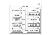
- FIG. 3 is a diagram showing a configuration example of the design device according to the first embodiment.
- the design device 10 receives input of information observed by the monitoring device 20 .
- the design apparatus 10 receives inputs of the topology of the communication network N and the exchange traffic.
- the design device 10 also outputs the route information to the control device 30 .
- the design device 10 has an interface section 11, a storage section 12 and a control section 13.
- the interface unit 11 is an interface for inputting and outputting data.
- the interface unit 11 is a NIC (Network Interface Card).
- the interface unit 11 can transmit and receive data to and from other devices.
- the interface unit 11 may be connected to an input device such as a mouse or a keyboard. Also, the interface unit 11 may be connected to an output device such as a display and a speaker. Thereby, the interface unit 11 functions as an interface with the network operator.
- the storage unit 12 is a storage device such as an HDD (Hard Disk Drive), an SSD (Solid State Drive), an optical disc, or the like.
- the storage unit 12 may be a semiconductor memory capable of rewriting data such as RAM (Random Access Memory), flash memory, NVSRAM (Non Volatile Static Random Access Memory).
- the storage unit 12 stores an OS (Operating System) and various programs executed by the design device 10 .
- the storage unit 12 stores a route DB 121, a topology DB 122 and a traffic DB 123.
- the route DB 121 holds route information for each logical path set between a start node and an end node. A method of calculating route information will be described later.
- the topology DB 122 holds connection information between nodes and links, and capacity information for each link. Also, the traffic DB 123 manages traffic information for each link and exchange traffic information for each logical path.
- the design device 10 calculates route information from the topology DB 122 and the traffic DB 123, and stores the calculated route information in the route DB 121.
- the design device 10 may also output the calculated route information.
- the control unit 13 controls the design device 10 as a whole.
- the control unit 13 includes, for example, electronic circuits such as CPU (Central Processing Unit), MPU (Micro Processing Unit), GPU (Graphics Processing Unit), ASIC (Application Specific Integrated Circuit), FPGA (Field Programmable Gate Array), etc. It is an integrated circuit.
- the control unit 13 also has an internal memory for storing programs defining various processing procedures and control data, and executes each processing using the internal memory.
- the control unit 13 functions as various processing units by running various programs.
- the control unit 13 has a shortest path calculation unit 131 , an optimization unit 132 , an approximation calculation unit 133 and a mapping unit 134 .
- the shortest path calculation unit 131 calculates the shortest path between the specified start node and end node.
- the optimization unit 132 optimizes the traffic volume assigned to each link between adjacent nodes included in the network with a first granularity. For example, the optimization unit 132 optimizes the AC traffic volume with a real number solution. For example, the first granularity is real numbers.
- the approximation calculation unit 133 calculates an approximate solution by approximating the traffic volume optimized with the first granularity with the second granularity.
- the approximation calculator 133 approximates a real number solution with an integer solution.
- the second granularity is an integer.
- the mapping unit 134 maps the logical path to each of the paths formed by the links according to the traffic volume approximated by the approximation calculation unit 133 .
- FIG. 5 is a diagram for explaining AC traffic.
- the exchange traffic represents the amount of traffic on the route (set of links) between the start node and the end node, not the total amount of traffic flowing through the links between adjacent nodes.
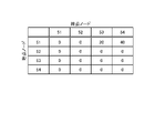
- the alternating traffic between node 51 and node 54 is 40 Gbps. Also, the AC traffic between the node 51 and the node 52 is 20 Gbps.
- FIG. 6 is a diagram showing an example of AC traffic. When two alternating traffics are generated as shown in FIG. 5, matrix notation as shown in the table of FIG. 6 is given.
- FIG. 4 is a diagram for explaining the flow of route calculation.
- Path resolution is the minimum granularity (for example, an integer) of traffic volume that can be set for a route.
- the unit of traffic volume that can be set for a route is determined.
- This unit corresponds to the minimum granularity. For example, as shown in FIG. 4, if the allocatable unit is 1G (bps), the minimum granularity is an integer.
- step S1 of Fig. 4 the optimization unit 132 calculates the optimum route as a real number solution from the alternating traffic and the topology. For example, the optimization unit 132 calculates the real number solution by the method described in Non-Patent Document 2.
- the optimization unit 132 calculates the traffic volume of the link between the nodes 51 and 53 as a real number such as 34.77G. Also, the optimization unit 132 calculates the traffic volume of the link between the node 53 and the node 54 as 29.84G.
- Non-Patent Document 2 since the solution calculated by the linear programming method described in Non-Patent Document 2 is a real number solution, it is a solution with a granularity that cannot be set with the given path resolution.
- step S2 the approximation calculation unit 133 approximates the solution calculated by the optimization unit 132 with a value that is a multiple of the path resolution, that is, the minimum granularity. For example, the approximation calculation unit 133 rounds off or truncates digits lower than the path resolution (here, the first decimal place and below).
- the approximation calculation unit 133 approximates the traffic volume of the link between the nodes 51 and 53 from 34.77G to 35G. Also, the approximation calculation unit 133 approximates the traffic volume of the link between the node 53 and the node 54 from 29.84G to 30G.
- step S3 the mapping unit 134 maps traffic onto each route. At this time, the mapping unit 134 performs mapping so that the traffic volume assigned to each link is as close as possible to the calculation result of the approximation calculation unit 133 .
- the mapping unit 134 maps 30 logical paths of 1G to the route between the nodes 51 and 54 and passing through the node 53 .
- the design processing (various calculations and mapping) by the design device 10 of this embodiment may be performed not only when initially designing the path of the communication network N, but also when the exchange traffic fluctuates.
- the design device 10 can recalculate the traffic volume and obtain the total difference from the state before the AC traffic fluctuates. Further, the design device 10 may calculate a route between specified grounds and obtain a difference only between the specified grounds to obtain a solution to traffic fluctuations during network operation.
- FIG. 7 is a flow chart showing the flow of processing of the design device according to the first embodiment. As shown in FIG. 7, the design device 10 calculates a real number solution for the traffic volume of each link (step S10).
- the design device 10 approximates the real number solution with the minimum granularity (for example, integers) (step S20). Then, the design device 10 maps the logical path to each route based on the approximated integer solution (step S30).
- the minimum granularity for example, integers
- FIG. 8 is a flowchart showing the flow of mapping processing.
- the process shown in FIG. 8 corresponds to the process of step S30 in FIG. Also, each step in FIG. 7 and the example in FIG. 9 will be appropriately associated with each other for explanation.
- FIG. 9 is a diagram illustrating an example of mapping processing.
- the mapping unit 134 selects a pair of a start node and an end node (selected ground) (step S301).
- the mapping unit 134 selects the node 51 in the approximated route information as the start node and selects the node 54 as the end node. At this time, nodes 51 and 54 are selected.
- the real number solution is calculated for all pairs of the start node and the end point node. You can say
- the shortest route calculation unit 131 calculates a minimum link cost route using the remaining capacity (approximated traffic volume) as a link cost, and calculates a plurality of route candidates (step S302).
- the shortest route calculator 131 calculates the following route candidates.
- the shortest path calculation unit 131 uses the Dijkstra method to delete links that have been used once and calculates k paths, and uses the K-shortest path algorithm to calculate k paths with overlapping link usage. Multiple route candidates can be calculated by a method, a method of calculating disjoint K routes using the Subal method, or the like.
- FIG. 10 is a diagram for explaining the Subal method. As shown in FIG. 10, the Subal method is performed by the following procedure. (1) Calculate the shortest cost path by Dijkstra's method or the like. (2) Links on the shortest cost path are reversed and the link cost is made negative. (3) Calculate the shortest cost path by the Bellman-Ford method or the like. (4) Combine the two path calculation results, remove the common part, and obtain the redundant path.
- the Subal method is a node/link redundant path calculation algorithm. According to the Subal method, node/link redundant paths can always be found if they exist. The Subal method finds a pair that minimizes the sum of the costs of the working and protection paths. On the other hand, in the method of applying the Dijkstra method (shortest path search algorithm) twice, even if a node/link redundant path exists, it may not be found.
- the mapping unit 134 attempts traffic mapping with a given resolution for the route candidates for the selected destination, starting with the one with the smallest total link cost (step S303). In the example of FIG. 9, the mapping unit 134 attempts mapping to the first route candidate with the smallest total link cost in the first round.
- mapping unit 134 proceeds to step S306.
- the mapping unit 134 updates the remaining capacity (step S306). In the example of FIG. 9, the mapping unit 134 updates the remaining capacity of each link of the first route candidate in the first round.
- the link cost of the link whose remaining capacity has been updated to 0 is considered to be a sufficiently large value (for example, infinite) from the next round onwards.
- step S304 If none of the route candidates can be mapped (step S304, No), the mapping unit 134 proceeds to step S305. Then, the mapping unit 134 attempts traffic mapping for the route with the largest total remaining capacity (step S305).
- mapping unit 134 allocates all of the requested traffic volume (the volume of AC traffic occurring in the selected destination) (step S307, Yes)
- the process proceeds to step S308.
- the mapping unit 134 if the mapping unit 134 has not allocated all of the requested traffic volume (step S307, No), the mapping unit 134 returns to step S302 and repeats the processing.
- mapping unit 134 when the mapping unit 134 has executed processing for all pairs (step S308, Yes), the processing ends. On the other hand, when the mapping unit 134 has not executed the processing for all the pairs (step S308, No), the mapping unit 134 returns to step S301 and repeats the processing.
- the mapping unit 134 gives priority to mapping to a route with a small approximated traffic volume, and when the approximated traffic volume is insufficient, preferentially maps to a route with the largest approximated traffic volume. conduct.
- traffic is mapped in order from the route with the least remaining capacity, and when the remaining capacity becomes 0 or less, the link cost is treated as a large value, so the traffic is mapped to the route with the remaining capacity. It's going to be broken.
- the amount of traffic to be mapped is uniform according to the resolution, depending on whether the method of allocating the route with the least remaining capacity or conversely, the method of allocating the traffic volume with the highest remaining capacity only changes the capacity of the mapping destination. Therefore, it is assumed that there is no difference in performance.
- the optimization unit 132 optimizes the traffic volume assigned to each link between adjacent nodes included in the network at the first granularity.
- the approximate calculation unit 133 calculates an approximate solution by approximating the traffic volume optimized with the first granularity with the second granularity.
- the conventional technology has the problem that it is not practical because it cannot be actually set in the network because it is a real number solution, or it cannot be calculated on a carrier network scale.
- a solution that can actually be set is calculated while approximating the optimum solution.
- route design with high traffic accommodation efficiency has the effect of reducing facility costs.
- the optimization unit 132 optimizes the AC traffic volume with a real number solution.
- the approximation calculator 133 approximates the real number solution with an integer solution. This enables mapping of logical paths in units of 1 Gbps.
- mapping unit 134 maps the logical path to each route configured by links according to the traffic volume approximated by the approximation calculation unit 133 .
- the design device 10 can reflect the result of the approximate calculation in the actual communication network.
- mapping unit 134 gives priority to mapping to a route with a small approximated traffic volume, and if the approximated traffic volume is insufficient, preferentially maps to a route with the largest approximated traffic volume. Thereby, the design apparatus 10 can realize efficient mapping.
- each component of each device illustrated is functionally conceptual, and does not necessarily need to be physically configured as illustrated.
- the specific form of distribution and integration of each device is not limited to the illustrated one, and all or part of them can be functionally or physically distributed or Can be integrated and configured.
- each processing function performed by each device may be implemented in whole or in part by a CPU and a program analyzed and executed by the CPU, or implemented as hardware based on wired logic. Note that the program may be executed not only by the CPU but also by other processors such as a GPU.
- the design apparatus 10 can be implemented by installing a design program for executing the above design processing as package software or online software on a desired computer.
- the information processing device can function as the design device 10 by causing the information processing device to execute the above design program.
- the information processing apparatus referred to here includes a desktop or notebook personal computer.
- information processing devices include mobile communication terminals such as smartphones, mobile phones and PHS (Personal Handyphone Systems), and slate terminals such as PDAs (Personal Digital Assistants).
- the design device 10 can also be implemented as a design server device that uses a terminal device used by a user as a client and provides the client with services related to the above-described design processing.
- the design server device is implemented as a server device that provides a design service that inputs the alternating traffic and topology of a communication network and outputs the result of logical path mapping.
- the design server device may be implemented as a web server, or may be implemented as a cloud that provides services related to the above design processing through outsourcing.
- FIG. 11 is a diagram showing an example of a computer that executes a design program.
- the computer 1000 has a memory 1010 and a CPU 1020, for example.
- Computer 1000 also has hard disk drive interface 1030 , disk drive interface 1040 , serial port interface 1050 , video adapter 1060 and network interface 1070 . These units are connected by a bus 1080 .
- the memory 1010 includes a ROM (Read Only Memory) 1011 and a RAM (Random Access Memory) 1012 .
- the ROM 1011 stores a boot program such as BIOS (Basic Input Output System).
- BIOS Basic Input Output System
- Hard disk drive interface 1030 is connected to hard disk drive 1090 .
- a disk drive interface 1040 is connected to the disk drive 1100 .
- a removable storage medium such as a magnetic disk or optical disk is inserted into the disk drive 1100 .
- Serial port interface 1050 is connected to mouse 1110 and keyboard 1120, for example.
- Video adapter 1060 is connected to display 1130, for example.
- the hard disk drive 1090 stores, for example, an OS 1091, application programs 1092, program modules 1093, and program data 1094. That is, the program that defines each process of the design apparatus 10 is implemented as a program module 1093 in which computer-executable code is described. Program modules 1093 are stored, for example, on hard disk drive 1090 .
- the hard disk drive 1090 stores a program module 1093 for executing processing similar to the functional configuration in the design apparatus 10 .
- the hard disk drive 1090 may be replaced by an SSD (Solid State Drive).
- the setting data used in the processing of the above-described embodiment is stored as program data 1094 in the memory 1010 or the hard disk drive 1090, for example. Then, the CPU 1020 reads the program modules 1093 and program data 1094 stored in the memory 1010 and the hard disk drive 1090 to the RAM 1012 as necessary, and executes the processes of the above-described embodiments.
- the program modules 1093 and program data 1094 are not limited to being stored in the hard disk drive 1090, but may be stored in a removable storage medium, for example, and read by the CPU 1020 via the disk drive 1100 or the like. Alternatively, the program modules 1093 and program data 1094 may be stored in another computer connected via a network (LAN (Local Area Network), WAN (Wide Area Network), etc.). Program modules 1093 and program data 1094 may then be read by CPU 1020 through network interface 1070 from other computers.
- LAN Local Area Network
- WAN Wide Area Network
Landscapes
- Engineering & Computer Science (AREA)
- Computer Networks & Wireless Communication (AREA)
- Signal Processing (AREA)
- Data Exchanges In Wide-Area Networks (AREA)
Priority Applications (3)
| Application Number | Priority Date | Filing Date | Title |
|---|---|---|---|
| PCT/JP2021/005371 WO2022172423A1 (ja) | 2021-02-12 | 2021-02-12 | 設計装置、設計方法及び設計プログラム |
| US18/276,953 US20240121190A1 (en) | 2021-02-12 | 2021-02-12 | Design device, design method, and design program |
| JP2022581134A JP7605231B2 (ja) | 2021-02-12 | 2021-02-12 | 設計装置、設計方法及び設計プログラム |
Applications Claiming Priority (1)
| Application Number | Priority Date | Filing Date | Title |
|---|---|---|---|
| PCT/JP2021/005371 WO2022172423A1 (ja) | 2021-02-12 | 2021-02-12 | 設計装置、設計方法及び設計プログラム |
Publications (1)
| Publication Number | Publication Date |
|---|---|
| WO2022172423A1 true WO2022172423A1 (ja) | 2022-08-18 |
Family
ID=82838551
Family Applications (1)
| Application Number | Title | Priority Date | Filing Date |
|---|---|---|---|
| PCT/JP2021/005371 Ceased WO2022172423A1 (ja) | 2021-02-12 | 2021-02-12 | 設計装置、設計方法及び設計プログラム |
Country Status (3)
| Country | Link |
|---|---|
| US (1) | US20240121190A1 (https=) |
| JP (1) | JP7605231B2 (https=) |
| WO (1) | WO2022172423A1 (https=) |
Citations (1)
| Publication number | Priority date | Publication date | Assignee | Title |
|---|---|---|---|---|
| JP2000232395A (ja) * | 1998-11-05 | 2000-08-22 | Lucent Technol Inc | 最小コストでエンドノードからコアネットワークへのトラヒックを運ぶためのネットワーク設計の線形計画方法 |
Family Cites Families (9)
| Publication number | Priority date | Publication date | Assignee | Title |
|---|---|---|---|---|
| US6069894A (en) * | 1995-06-12 | 2000-05-30 | Telefonaktiebolaget Lm Ericsson | Enhancement of network operation and performance |
| US5854903A (en) * | 1995-11-07 | 1998-12-29 | Lucent Technologies Inc. | Optimization method for routing and logical network design in multi-service networks |
| US6331986B1 (en) * | 1998-04-24 | 2001-12-18 | Lucent Technologies Inc. | Method for resource allocation and routing in multi-service virtual private networks |
| AU2001281240A1 (en) * | 2000-08-10 | 2002-02-25 | University Of Pittsburgh | Apparatus and method for spare capacity allocation |
| GB0026703D0 (en) * | 2000-11-01 | 2000-12-20 | Parc Technologies Ltd | Traffic flow optimisation system |
| GB2386033B (en) * | 2002-03-01 | 2005-08-24 | Parc Technologies Ltd | Traffic flow optimisation system |
| US7593348B2 (en) * | 2004-02-11 | 2009-09-22 | Alcatel-Lucent Usa Inc. | Traffic-independent allocation of working and restoration capacity in networks |
| JP5655619B2 (ja) * | 2011-02-21 | 2015-01-21 | 富士通株式会社 | ネットワーク設計システム |
| JP7548339B2 (ja) * | 2021-02-02 | 2024-09-10 | 日本電信電話株式会社 | トラヒックエンジニアリング装置、トラヒックエンジニアリング方法およびトラヒックエンジニアリングプログラム |
-
2021
- 2021-02-12 JP JP2022581134A patent/JP7605231B2/ja active Active
- 2021-02-12 US US18/276,953 patent/US20240121190A1/en not_active Abandoned
- 2021-02-12 WO PCT/JP2021/005371 patent/WO2022172423A1/ja not_active Ceased
Patent Citations (1)
| Publication number | Priority date | Publication date | Assignee | Title |
|---|---|---|---|---|
| JP2000232395A (ja) * | 1998-11-05 | 2000-08-22 | Lucent Technol Inc | 最小コストでエンドノードからコアネットワークへのトラヒックを運ぶためのネットワーク設計の線形計画方法 |
Non-Patent Citations (2)
| Title |
|---|
| CAI, DONGFENG ET AL.: "An Approximate Solution Method for Discrete Constraint Optimization Problem Using Linear Programming", JOURNAL OF JAPANESE SOCIETY FOR ARTIFICIAL INTELLIGENCE, vol. 14, no. 2, 1 March 1999 (1999-03-01), pages 334 - 341 * |
| WANG, YUFEI ET AL.: "Explicit routing algorithms for Internet traffic engineering", PROCEEDINGS EIGHT INTERNATIONAL CONFERENCE ON COMPUTER COMMUNICATIONS AND NETWORKS, 11 October 1999 (1999-10-11), pages 582 - 588, XP010359627, DOI: 10.1109/ICCCN.1999.805577 * |
Also Published As
| Publication number | Publication date |
|---|---|
| JPWO2022172423A1 (https=) | 2022-08-18 |
| US20240121190A1 (en) | 2024-04-11 |
| JP7605231B2 (ja) | 2024-12-24 |
Similar Documents
| Publication | Publication Date | Title |
|---|---|---|
| Kuo et al. | Deploying chains of virtual network functions: On the relation between link and server usage | |
| Wang et al. | Joint optimization of service function chaining and resource allocation in network function virtualization | |
| CN112585585B (zh) | 基于可扩展遗传算法的虚拟化系统的虚拟网络功能的联合放置和链接 | |
| Avin et al. | Demand-aware network design with minimal congestion and route lengths | |
| Cohen et al. | Almost optimal virtual machine placement for traffic intense data centers | |
| JP6470426B2 (ja) | リソース割当装置及びリソース割当方法 | |
| US20230308352A1 (en) | Optimization method and system for minimizing network energy consumption based on traffic grooming | |
| GB2536606A (en) | Network topology optimization | |
| WO2014155292A1 (en) | A method and system to allocate bandwidth for heterogeneous bandwidth request in cloud computing networks | |
| WO2020128569A1 (en) | Migrating services in data communication networks | |
| US10673764B2 (en) | Distributed affinity tracking for network connections | |
| Paschos et al. | Network slicing with splittable flows is hard | |
| Sørensen et al. | A metaheuristic scheduler for time division multiplexed networks-on-chip | |
| Madani et al. | Deploying disaster-resilient service function chains using adaptive multi-path routing | |
| WO2018029913A1 (ja) | リソース割当装置及びリソース割当方法 | |
| Józsa et al. | On the solution of reroute sequence planning problem in MPLS networks | |
| GB2571333A (en) | Integrated circuit design | |
| Lu et al. | Cost-efficient resource provisioning in delay-sensitive cooperative fog computing | |
| CN113078942B (zh) | 一种基于相关光路资源感知的生存性虚拟网络映射方法 | |
| JP7605231B2 (ja) | 設計装置、設計方法及び設計プログラム | |
| US10873502B2 (en) | System and method for joint embedding and backup provisioning in virtual networks | |
| Huang et al. | An efficient joint node and link mapping approach based on genetic algorithm for network virtualization | |
| Chuprikov et al. | How to implement complex policies on existing network infrastructure | |
| Yao et al. | VM migration planning in software-defined data center networks | |
| CN108520025B (zh) | 一种服务节点确定方法、装置、设备及介质 |
Legal Events
| Date | Code | Title | Description |
|---|---|---|---|
| ENP | Entry into the national phase |
Ref document number: 2022581134 Country of ref document: JP Kind code of ref document: A |
|
| WWE | Wipo information: entry into national phase |
Ref document number: 18276953 Country of ref document: US |
|
| NENP | Non-entry into the national phase |
Ref country code: DE |
|
| 122 | Ep: pct application non-entry in european phase |
Ref document number: 21925674 Country of ref document: EP Kind code of ref document: A1 |