WO2022171146A1 - Automatic cleaning device - Google Patents
Automatic cleaning device Download PDFInfo
- Publication number
- WO2022171146A1 WO2022171146A1 PCT/CN2022/075731 CN2022075731W WO2022171146A1 WO 2022171146 A1 WO2022171146 A1 WO 2022171146A1 CN 2022075731 W CN2022075731 W CN 2022075731W WO 2022171146 A1 WO2022171146 A1 WO 2022171146A1
- Authority
- WO
- WIPO (PCT)
- Prior art keywords
- connecting rod
- fixing bracket
- cleaning
- cleaning device
- automatic cleaning
- Prior art date
Links
- 238000004140 cleaning Methods 0.000 title claims abstract description 303
- 238000007667 floating Methods 0.000 claims abstract description 23
- 238000005108 dry cleaning Methods 0.000 claims description 61
- 230000009471 action Effects 0.000 claims description 12
- 238000000034 method Methods 0.000 claims description 10
- 230000000630 rising effect Effects 0.000 claims description 9
- XLYOFNOQVPJJNP-UHFFFAOYSA-N water Substances O XLYOFNOQVPJJNP-UHFFFAOYSA-N 0.000 description 69
- 230000033001 locomotion Effects 0.000 description 48
- 239000000428 dust Substances 0.000 description 40
- 239000000758 substrate Substances 0.000 description 39
- 230000007246 mechanism Effects 0.000 description 31
- 210000000078 claw Anatomy 0.000 description 28
- 238000010586 diagram Methods 0.000 description 25
- 239000000306 component Substances 0.000 description 11
- 230000000694 effects Effects 0.000 description 11
- 239000007788 liquid Substances 0.000 description 9
- 238000005096 rolling process Methods 0.000 description 8
- 230000005540 biological transmission Effects 0.000 description 7
- 230000007613 environmental effect Effects 0.000 description 7
- 230000006870 function Effects 0.000 description 7
- 238000010408 sweeping Methods 0.000 description 7
- 239000000463 material Substances 0.000 description 6
- 230000003139 buffering effect Effects 0.000 description 5
- 230000005484 gravity Effects 0.000 description 5
- 239000012790 adhesive layer Substances 0.000 description 4
- 230000008447 perception Effects 0.000 description 4
- 230000000712 assembly Effects 0.000 description 3
- 238000000429 assembly Methods 0.000 description 3
- 230000006399 behavior Effects 0.000 description 3
- 238000013461 design Methods 0.000 description 3
- 230000006872 improvement Effects 0.000 description 3
- 230000003993 interaction Effects 0.000 description 3
- 230000008569 process Effects 0.000 description 3
- 230000035939 shock Effects 0.000 description 3
- 241001417527 Pempheridae Species 0.000 description 2
- 238000001514 detection method Methods 0.000 description 2
- 238000006073 displacement reaction Methods 0.000 description 2
- 239000011521 glass Substances 0.000 description 2
- 238000012544 monitoring process Methods 0.000 description 2
- 238000012545 processing Methods 0.000 description 2
- WHXSMMKQMYFTQS-UHFFFAOYSA-N Lithium Chemical compound [Li] WHXSMMKQMYFTQS-UHFFFAOYSA-N 0.000 description 1
- 230000003044 adaptive effect Effects 0.000 description 1
- 239000000853 adhesive Substances 0.000 description 1
- 230000001070 adhesive effect Effects 0.000 description 1
- 230000008901 benefit Effects 0.000 description 1
- 230000008859 change Effects 0.000 description 1
- 230000000739 chaotic effect Effects 0.000 description 1
- 230000003749 cleanliness Effects 0.000 description 1
- 230000009194 climbing Effects 0.000 description 1
- 230000006835 compression Effects 0.000 description 1
- 238000007906 compression Methods 0.000 description 1
- 239000008358 core component Substances 0.000 description 1
- 230000008878 coupling Effects 0.000 description 1
- 238000010168 coupling process Methods 0.000 description 1
- 238000005859 coupling reaction Methods 0.000 description 1
- 238000013016 damping Methods 0.000 description 1
- 239000013013 elastic material Substances 0.000 description 1
- 230000003028 elevating effect Effects 0.000 description 1
- 239000004744 fabric Substances 0.000 description 1
- 239000012530 fluid Substances 0.000 description 1
- 229910052744 lithium Inorganic materials 0.000 description 1
- 238000012423 maintenance Methods 0.000 description 1
- 229910052987 metal hydride Inorganic materials 0.000 description 1
- 238000012986 modification Methods 0.000 description 1
- 230000004048 modification Effects 0.000 description 1
- 230000008855 peristalsis Effects 0.000 description 1
- 230000002572 peristaltic effect Effects 0.000 description 1
- 230000000750 progressive effect Effects 0.000 description 1
- 239000007779 soft material Substances 0.000 description 1
- 239000008400 supply water Substances 0.000 description 1
- 239000000725 suspension Substances 0.000 description 1
- 230000032258 transport Effects 0.000 description 1
- 238000004804 winding Methods 0.000 description 1
Images


Classifications
-
- A—HUMAN NECESSITIES
- A47—FURNITURE; DOMESTIC ARTICLES OR APPLIANCES; COFFEE MILLS; SPICE MILLS; SUCTION CLEANERS IN GENERAL
- A47L—DOMESTIC WASHING OR CLEANING; SUCTION CLEANERS IN GENERAL
- A47L11/00—Machines for cleaning floors, carpets, furniture, walls, or wall coverings
- A47L11/40—Parts or details of machines not provided for in groups A47L11/02 - A47L11/38, or not restricted to one of these groups, e.g. handles, arrangements of switches, skirts, buffers, levers
- A47L11/4052—Movement of the tools or the like perpendicular to the cleaning surface
- A47L11/4055—Movement of the tools or the like perpendicular to the cleaning surface for lifting the tools to a non-working position
-
- A—HUMAN NECESSITIES
- A47—FURNITURE; DOMESTIC ARTICLES OR APPLIANCES; COFFEE MILLS; SPICE MILLS; SUCTION CLEANERS IN GENERAL
- A47L—DOMESTIC WASHING OR CLEANING; SUCTION CLEANERS IN GENERAL
- A47L11/00—Machines for cleaning floors, carpets, furniture, walls, or wall coverings
- A47L11/40—Parts or details of machines not provided for in groups A47L11/02 - A47L11/38, or not restricted to one of these groups, e.g. handles, arrangements of switches, skirts, buffers, levers
- A47L11/4052—Movement of the tools or the like perpendicular to the cleaning surface
-
- A—HUMAN NECESSITIES
- A47—FURNITURE; DOMESTIC ARTICLES OR APPLIANCES; COFFEE MILLS; SPICE MILLS; SUCTION CLEANERS IN GENERAL
- A47L—DOMESTIC WASHING OR CLEANING; SUCTION CLEANERS IN GENERAL
- A47L11/00—Machines for cleaning floors, carpets, furniture, walls, or wall coverings
- A47L11/24—Floor-sweeping machines, motor-driven
-
- A—HUMAN NECESSITIES
- A47—FURNITURE; DOMESTIC ARTICLES OR APPLIANCES; COFFEE MILLS; SPICE MILLS; SUCTION CLEANERS IN GENERAL
- A47L—DOMESTIC WASHING OR CLEANING; SUCTION CLEANERS IN GENERAL
- A47L11/00—Machines for cleaning floors, carpets, furniture, walls, or wall coverings
- A47L11/28—Floor-scrubbing machines, motor-driven
- A47L11/284—Floor-scrubbing machines, motor-driven having reciprocating tools
-
- A—HUMAN NECESSITIES
- A47—FURNITURE; DOMESTIC ARTICLES OR APPLIANCES; COFFEE MILLS; SPICE MILLS; SUCTION CLEANERS IN GENERAL
- A47L—DOMESTIC WASHING OR CLEANING; SUCTION CLEANERS IN GENERAL
- A47L11/00—Machines for cleaning floors, carpets, furniture, walls, or wall coverings
- A47L11/40—Parts or details of machines not provided for in groups A47L11/02 - A47L11/38, or not restricted to one of these groups, e.g. handles, arrangements of switches, skirts, buffers, levers
- A47L11/4013—Contaminants collecting devices, i.e. hoppers, tanks or the like
-
- A—HUMAN NECESSITIES
- A47—FURNITURE; DOMESTIC ARTICLES OR APPLIANCES; COFFEE MILLS; SPICE MILLS; SUCTION CLEANERS IN GENERAL
- A47L—DOMESTIC WASHING OR CLEANING; SUCTION CLEANERS IN GENERAL
- A47L11/00—Machines for cleaning floors, carpets, furniture, walls, or wall coverings
- A47L11/40—Parts or details of machines not provided for in groups A47L11/02 - A47L11/38, or not restricted to one of these groups, e.g. handles, arrangements of switches, skirts, buffers, levers
- A47L11/4036—Parts or details of the surface treating tools
- A47L11/4041—Roll shaped surface treating tools
-
- A—HUMAN NECESSITIES
- A47—FURNITURE; DOMESTIC ARTICLES OR APPLIANCES; COFFEE MILLS; SPICE MILLS; SUCTION CLEANERS IN GENERAL
- A47L—DOMESTIC WASHING OR CLEANING; SUCTION CLEANERS IN GENERAL
- A47L11/00—Machines for cleaning floors, carpets, furniture, walls, or wall coverings
- A47L11/40—Parts or details of machines not provided for in groups A47L11/02 - A47L11/38, or not restricted to one of these groups, e.g. handles, arrangements of switches, skirts, buffers, levers
- A47L11/4061—Steering means; Means for avoiding obstacles; Details related to the place where the driver is accommodated
-
- A—HUMAN NECESSITIES
- A47—FURNITURE; DOMESTIC ARTICLES OR APPLIANCES; COFFEE MILLS; SPICE MILLS; SUCTION CLEANERS IN GENERAL
- A47L—DOMESTIC WASHING OR CLEANING; SUCTION CLEANERS IN GENERAL
- A47L11/00—Machines for cleaning floors, carpets, furniture, walls, or wall coverings
- A47L11/40—Parts or details of machines not provided for in groups A47L11/02 - A47L11/38, or not restricted to one of these groups, e.g. handles, arrangements of switches, skirts, buffers, levers
- A47L11/4072—Arrangement of castors or wheels
-
- A—HUMAN NECESSITIES
- A47—FURNITURE; DOMESTIC ARTICLES OR APPLIANCES; COFFEE MILLS; SPICE MILLS; SUCTION CLEANERS IN GENERAL
- A47L—DOMESTIC WASHING OR CLEANING; SUCTION CLEANERS IN GENERAL
- A47L2201/00—Robotic cleaning machines, i.e. with automatic control of the travelling movement or the cleaning operation
- A47L2201/04—Automatic control of the travelling movement; Automatic obstacle detection
Definitions
- the present invention relates to the technical field of cleaning robots, in particular to an automatic cleaning device.
- cleaning robots mainly include sweeping robots and mopping robots.
- the functions of sweeping robots and mopping robots are relatively simple, and they can only be used for sweeping or mopping. If you want to sweep and mop the floor at the same time, you must prepare two sets of equipment at the same time. Due to the unreasonable structural design, it will occupy double the space and affect the settings of other components.
- the main brush part of the sweeping robot is generally connected by an independent spring or a long-handled lever structure, which has low structural rigidity and service life, and is easy to get stuck when encountering obstacles, thereby easily damaging the main brush.
- the brush part makes the overall structure of the cleaning robot less stable, so it is necessary to provide a stable and reliable cleaning robot with a structure that can passively lift the main brush.
- the purpose of the present invention is to provide an automatic cleaning device that can solve one of the above technical problems.
- the specific plans are as follows:
- the present invention provides an automatic cleaning device, comprising:
- a mobile platform 100 configured to move automatically on the operating surface
- the cleaning module 150 disposed on the mobile platform 100, includes:
- the wet cleaning module 400 is configured to clean at least a part of the operation surface in a wet cleaning manner
- the dry cleaning module 151 is configured to clean at least a part of the operation surface by dry cleaning
- the floating lifting structure 600 is connected to the dry cleaning module 151 and is configured to enable the dry cleaning module 151 to passively move up and down relative to the moving platform 100 .
- the floating lifting structure 600 is a parallelogram four-link lifting structure, configured to passively switch the dry cleaning module 151 between a rising state and a sinking state under the action of an external force.
- the floating lifting structure 600 includes:
- first fixing bracket 601 is fixedly connected to the mobile platform 100;
- the second fixing bracket 602 is fixedly connected to the dry cleaning module 151;
- One end of the connecting rod pair 603 is rotatably connected to the first fixing bracket 601 through a movable stud, and the other end is rotatably connected to the second fixing bracket 602 through a movable stud.
- the connecting rod pair 603 includes:
- One end of the first connecting rod pair 6031 is rotatably connected to the first end of the first fixing bracket 601 through a movable stud, and the other end is rotatably connected to the first end of the second fixing bracket 602 through a movable stud end;
- the second connecting rod pair 6032 is disposed opposite to the first connecting rod pair 6031, one end is rotatably connected to the second end of the first fixing bracket 601 through the movable stud, and the other end is rotatably connected through the movable stud connected to the second end of the second fixing bracket 602 .
- the first connecting rod pair 6031 includes a first connecting rod 60311 and a second connecting rod 60312 arranged in parallel, and one end of the first connecting rod 60311 and the second connecting rod 60312 is provided with a first shaft hole, The other end is provided with a second shaft hole;
- the movable stud passes through the first shaft hole to rotatably fix the first connecting rod 60311 and the second connecting rod 60312 to the first end of the first fixing bracket 601, and the movable stud passes through The second shaft hole can rotate to fix the first connecting rod 60311 and the second connecting rod 60312 to the first end of the second fixing bracket 602 .
- the second connecting rod pair 6032 includes a third connecting rod 60321 and a fourth connecting rod 60322 arranged in parallel, and one end of the third connecting rod 60321 and the fourth connecting rod 60322 is provided with a third shaft hole, The other end is provided with a fourth shaft hole;
- the movable stud passes through the third shaft hole to rotatably fix the third connecting rod 60321 and the fourth connecting rod 60322 to the second end of the first fixing bracket 601, and the movable stud passes through The fourth shaft hole can rotate to fix the third connecting rod 60321 and the fourth connecting rod 60322 on the second end of the second fixing bracket 602 .
- the first fixing bracket 601 includes:
- the first fixing portion 6011 protrudes from the first fixing bracket 601 and extends laterally outward, and is used for carrying the first connecting rod pair 6031 .
- the first fixing bracket 601 further includes:
- the second fixing portion 6012 is symmetrically arranged with the first fixing portion 6011 and is used for carrying the second connecting rod pair 6032 .
- the floating lifting structure 600 further includes:
- the flexible connecting part is connected between the first fixing bracket 601 and the second fixing bracket 602.
- the second fixing bracket 602 is relatively opposite to the first fixing bracket 602 through the flexible connecting part.
- the fixed bracket 601 moves up and down.
- the first connecting rod pair 6031 or the second connecting rod pair 6032 is a hollow structure.
- the present invention also provides an automatic cleaning device, comprising:
- a mobile platform 100 configured to move automatically on the operating surface
- the cleaning module 150 disposed on the mobile platform 100, includes:
- the dry cleaning module 151 is configured to clean at least a part of the operation surface by dry cleaning
- the floating lifting structure 600 is connected to the dry cleaning module 151, and is configured to enable the dry cleaning module 151 to passively move up and down relative to the mobile platform 100; wherein, the dry cleaning module 151 Several claws 1511 are included, and the claws 1511 are located between the dry cleaning module 151 and the operation surface to be cleaned.
- the dry cleaning module 151 includes a main brush cover 152 and a rolling brush 15114 , and the rolling brush 15114 rotates in the main brush cover 152 to collect dust.
- the clamping claw 1511 is located on one side in the traveling direction of the automatic cleaning device at the bottom of the main brush cover 152 .
- the plurality of claws 1511 are evenly distributed on one side of the bottom of the main brush cover 152 in the traveling direction of the automatic cleaning device.
- the height of the claws 1511 is slightly lower than the height of the roller brush 15114 .
- the clamping claw 1511 includes an arc surface 15111, and the arc surface 15111 faces one side in the traveling direction of the automatic cleaning device.
- the claw 1511 includes a cut surface 15112, and the cut surface 15112 is located on both sides of the arc surface 15111 to reduce the traveling resistance.
- the projection of the arc surface 15111 along the rolling brush 15114 partially overlaps the rolling brush 15114 .
- the clamping claw 1511 further includes a support surface 15113 , and the support surface 15113 is connected to the arc surface 15111 .
- the support surface 15113 is a planar structure or an arched surface structure.
- the embodiment of the present invention has the following technical effects:
- the sweeping and mopping integrated cleaning device provided by the present invention can provide a more comprehensive cleaning function because the cleaning module of the automatic cleaning device is provided with a dry cleaning module and a wet cleaning module.
- the dry cleaning module by setting up a four-link floating lifting structure, the dry cleaning module is passively moved up and down relative to the mobile platform.
- the cleaning equipment encounters obstacles during the operation, It can easily cross the obstacles through the four-link floating lifting structure, and avoid the damage to the cleaning equipment caused by the obstacles.
- the four-link lifting module enhances the stability of the equipment and greatly increases the service life of the lifting structure; and in actual use, because the parallelogram structure has parallel rising and falling characteristics, so The floating lifting structure on both sides has better obstacle-crossing performance than the existing lifting structure, and it is less likely to be stuck by various obstacles.
- the integrated sweeping and mopping cleaning device provided by the present invention, by improving the structure of the main brush cover, in the direction of the dust inlet of the main brush cover, a row of tooth-shaped protruding claws are arranged, and the claws follow the circular shape of the main brush. Arc direction. After encountering an obstacle, with the lifting module, the main brush can be lifted up, thereby reducing the risk of slender objects such as wires getting stuck in the main brush, and also preventing the corner of the carpet from being directly stuck in the air duct of the main brush. Lift the robot up.
- FIG. 1 is a perspective view of an automatic cleaning apparatus according to an embodiment of the present invention.
- FIG. 2 is a schematic diagram of a bottom structure of an automatic cleaning device according to an embodiment of the present invention.
- FIG 3 is a perspective view of a one-side drive wheel assembly according to an embodiment of the present invention.
- FIG. 4 is a front view of a one-side drive wheel assembly according to an embodiment of the present invention.
- FIG. 5 is a perspective view of a dust box according to an embodiment of the present invention.
- FIG. 6 is a perspective view of a fan according to an embodiment of the present invention.
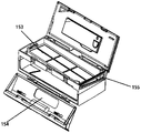
- FIG. 7 is a schematic diagram of an open state of the dust box according to an embodiment of the present invention.
- FIG. 8 is a schematic diagram of a combined state of a dust box and a fan according to an embodiment of the present invention.
- FIG. 9 is an exploded view of an automatic cleaning device according to an embodiment of the present invention.
- FIG. 10 is a structural diagram of a support platform of an automatic cleaning device according to an embodiment of the present invention.
- FIG. 11 is a structural diagram of a vibration member of an automatic cleaning device according to an embodiment of the present invention.
- FIG. 12 is a schematic diagram of a cleaning head driving mechanism based on a crank-slider mechanism according to another embodiment of the present invention.
- FIG. 13 is a schematic diagram of a cleaning head driving mechanism based on a double crank mechanism according to another embodiment of the present invention.
- FIG. 14 is a schematic diagram of a cleaning head driving mechanism based on a crank mechanism according to another embodiment of the present invention.
- FIG. 15 is a structural diagram of a vibration member according to an embodiment of the present invention.
- FIG. 16 is a schematic diagram of an assembly structure of a cleaning substrate according to an embodiment of the present invention.
- FIG. 17 is a structural diagram of a motor-driven clean water pump according to an embodiment of the present invention.
- FIG. 18 is a structural diagram of a motor-driven lifting module according to an embodiment of the present invention.
- FIG. 19 is a schematic diagram of a raised state of an automatic cleaning device according to an embodiment of the present invention.
- FIG. 20 is a schematic diagram of a sinking state of an automatic cleaning device according to an embodiment of the present invention.
- FIG. 21 is a schematic diagram of a raised state of the four-link lifting structure according to an embodiment of the present invention.
- FIG. 22 is a schematic diagram of the sinking state of the four-link lifting structure according to an embodiment of the present invention.
- FIG. 23 is a schematic structural diagram of the sinking state of the dry cleaning module according to an embodiment of the present invention.
- FIG. 24 is a schematic structural diagram of a dry cleaning module in a rising state according to an embodiment of the present invention.
- Mobile platform 100 rearward portion 110, forward portion 111, perception system 120, position determination device 121, buffer 122, cliff sensor 123, control system 130, drive system 140, drive wheel assembly 141, steering assembly 142, elastic element 143, drive motor 146, cleaning module 150, dry cleaning module 151, dust box 152, filter 153, dust suction port 154, air outlet 155, fan 156, energy system 160, human-computer interaction system 170, wet cleaning Assembly 400, cleaning head 410, drive unit 420, drive platform 421, support platform 422, motor 4211, drive wheel 4212, vibration member 4213, connecting rod 4214, vibration buffer device 4215, jaw 4216, clean water pump pipe 4218, clean water pump 4219, cleaning base plate 4221, elastic disassembly button 4229, assembly area 4224, snap position 4225, first chute 4222, second chute 4223, first slider 525, second slider 528, rotary end 512 (4227) , sliding end 514 (4226), first pivot 516 (624), second pivot 518 (626),
- first, second, third, etc. may be used for description in the embodiments of the present invention, these should not be limited to these terms. These terms are used only to distinguish.
- the first may also be referred to as the second, and similarly, the second may be referred to as the first without departing from the scope of the embodiments of the present invention.
- Fig. 1-2 is a schematic structural diagram of an automatic cleaning device according to an exemplary embodiment.
- the automatic cleaning device can be a vacuum suction robot, It can be a window climbing robot, etc.
- the automatic cleaning device can include a mobile platform 100 , a sensing system 120 , a control system 130 , a driving system 140 , a cleaning module 150 , an energy system 160 and a human-computer interaction system 170 . in:
- the mobile platform 100 may be configured to automatically move along the target direction on the operating surface.
- the operating surface may be the surface to be cleaned by the automatic cleaning device.
- the automatic cleaning device can be a mopping robot, and the automatic cleaning device works on the ground, where the ground is the operating surface; the automatic cleaning device can also be a window cleaning robot, and the automatic cleaning device is in the building.
- the outer surface of the glass works, the glass is the operation surface; the automatic cleaning equipment can also be a pipe cleaning robot, and the automatic cleaning equipment works on the inner surface of the pipe, and the inner surface of the pipe is the operation surface.
- the following description in this application takes a floor mopping robot as an example for illustration.
- the mobile platform 100 may be an autonomous mobile platform or a non-autonomous mobile platform.
- the autonomous mobile platform means that the mobile platform 100 itself can automatically and adaptively make operational decisions according to unexpected environmental inputs; the non-autonomous mobile platform itself cannot make adaptive decisions according to unexpected environmental inputs. Operational decisions, but can execute a given procedure or operate according to a certain logic.
- the target direction may be determined autonomously by the automatic cleaning device; when the mobile platform 100 is a non-autonomous mobile platform, the target direction may be set by the system or manually.
- the mobile platform 100 includes a forward portion 111 and a rearward portion 110 .
- Perception system 120 includes position determination device 121 located above mobile platform 100, buffer 122 located at forward portion 111 of mobile platform 100, cliff sensors 123 and ultrasonic sensors (not shown), infrared sensors located at the bottom of mobile platform 100 (not shown in the figure), magnetometer (not shown in the figure), accelerometer (not shown in the figure), gyroscope (not shown in the figure), odometer (not shown in the figure) and other sensors
- the device provides various position information and motion state information of the machine to the control system 130 .
- the automatic cleaning device can travel on the ground by various combinations of movements relative to the following three mutually perpendicular axes defined by the mobile platform 100: lateral axis x, Front and rear axis y and center vertical axis z.
- the forward drive direction along the front-rear axis y is designated “forward” and the rearward drive direction along the front-rear axis y is designated “rear”.
- the transverse axis x extends substantially along the axis defined by the center point of the drive wheel assembly 141 between the right and left wheels of the automatic cleaning apparatus.
- the automatic cleaning device can rotate around the x-axis.
- the automatic cleaning device can be rotated about the z-axis. In the forward direction of the automatic cleaning device, when the automatic cleaning device is inclined to the right of the Y-axis, it is “turn right", and when the automatic cleaning device is inclined to the left of the y-axis, it is “turn left”.
- cliff sensors 123 are provided on the bottom of the mobile platform 100 and at the front and rear of the driving wheel assembly 141 .
- the cliff sensors are used to prevent the automatic cleaning device from falling when it retreats, so as to prevent the automatic cleaning device from being affected by damage.
- the aforementioned "front” refers to the same side with respect to the traveling direction of the automatic cleaning device, and the aforementioned “rear” refers to the opposite side with respect to the traveling direction of the automatic cleaning device.
- the location determination device 121 includes, but is not limited to, a camera, a laser ranging device (LDS).
- LDS laser ranging device
- the various components in the perception system 120 can either operate independently or work together to more accurately achieve their intended functions.
- the surface to be cleaned is identified by the cliff sensor 123 and the ultrasonic sensor to determine the physical characteristics of the surface to be cleaned, including surface material, cleanliness, etc., and can be combined with cameras, laser ranging devices, etc. for more accurate determination.
- the ultrasonic sensor can determine whether the surface to be cleaned is a carpet. If the ultrasonic sensor determines that the surface to be cleaned is a carpet material, the control system 130 controls the automatic cleaning device to perform carpet mode cleaning.
- the forward portion 111 of the mobile platform 100 is provided with a bumper 122.
- the bumper 122 detects the travel path of the automatic cleaning device via a sensor system, such as an infrared sensor.
- a sensor system such as an infrared sensor.
- the control system 130 is provided on a circuit board in the mobile platform 100, and includes a computing processor, such as a central processing unit, an application processor, an application processing unit that communicates with non-transitory memory, such as hard disk, flash memory, random access memory,
- the device is configured to receive the environmental information sensed by the plurality of sensors from the perception system 120, and use a positioning algorithm, such as SLAM, to map the real-time situation in the environment where the automatic cleaning device is located according to the obstacle information fed back by the laser ranging device. map, and autonomously determine a driving path according to the environmental information and the environmental map, and then control the driving system 140 to perform operations such as forward, backward, and/or steering according to the autonomously determined driving path. Further, the control system 130 may also decide whether to start the cleaning module 150 to perform the cleaning operation according to the environmental information and the environmental map.
- control system 130 can combine the distance information and speed information fed back by the buffer 122 , the cliff sensor 123 and the ultrasonic sensor, infrared sensor, magnetometer, accelerometer, gyroscope, odometer and other sensing devices to comprehensively judge that the sweeper is currently in What working state, such as crossing the threshold, on the carpet, on the cliff, stuck above or below, the dust box is full, picked up, etc., will also give specific next action strategies for different situations, so that automatic cleaning The work of the device is more in line with the owner's requirements, and there is a better user experience. Further, the control system can plan the most efficient and reasonable cleaning path and cleaning method based on the real-time map information drawn by SLAM, which greatly improves the cleaning efficiency of automatic cleaning equipment.
- the drive system 140 may execute drive commands to steer the automated cleaning apparatus across the ground based on specific distance and angular information, such as x, y, and theta components.
- 3 and 4 are oblique views and front views of one side drive wheel assembly 141 in an embodiment of the present invention.
- the drive system 140 includes a drive wheel assembly 141, and the drive system 140 can control the left wheel and the right wheel at the same time.
- the drive system 140 preferably includes a left drive wheel assembly and a right drive wheel assembly, respectively.
- the left and right drive wheel assemblies are arranged symmetrically along the transverse axis defined by the mobile platform 100 .
- the driving wheel assembly includes a main body, a driving wheel and an elastic element.
- One end of the main body is connected to the frame, and the driving wheel is arranged in the main body and driven by the driving motor 146; the elastic element is connected between the main body and the frame, and the elastic element is connected to the frame. It is configured to provide elastic force between the frame and the main body, the drive motor 146 is located outside the drive wheel assembly 141, and the axis of the drive motor 146 is located in the cross-sectional projection of the drive wheel, and the drive wheel assembly 141 can also be connected to measure the drive current. circuit and odometer.
- the automatic cleaning equipment may include one or more steering assemblies 142, and the steering assemblies 142 may be driven wheels or driving wheels, and their structural forms Including but not limited to caster wheels, the steering assembly 142 may be located in front of the drive wheel assembly 141 .
- Drive motor 146 provides power for rotation of drive wheel assembly 141 and/or steering assembly 142 .
- the driving wheel assembly 141 can be detachably connected to the mobile platform 100 for easy disassembly and maintenance.
- the drive wheel may have an offset drop suspension system, movably fastened, eg, rotatably attached, to the automatic cleaning device moving platform 100, and grounded to a certain degree by elastic elements 143, such as tension springs or compression springs The force maintains the contact and traction with the ground, and at the same time, the cleaning module 150 of the automatic cleaning device also contacts the surface to be cleaned with a certain pressure.
- the energy system 160 includes rechargeable batteries, such as nickel-metal hydride batteries and lithium batteries.
- the rechargeable battery can be connected with a charging control circuit, a battery pack charging temperature detection circuit and a battery undervoltage monitoring circuit, and the charging control circuit, the battery pack charging temperature detection circuit, and the battery undervoltage monitoring circuit are then connected with the single-chip microcomputer control circuit.
- the host is charged by connecting to the charging pile through the charging electrode arranged on the side or below of the fuselage.
- the human-computer interaction system 170 includes buttons on the host panel, and the buttons are used for user selection of functions; it may also include a display screen and/or indicator lights and/or horns, and the display screen, indicator lights and horns can show the user the current state of the machine or Feature selections; may also include mobile client programs.
- the mobile phone client can show the user a map of the environment where the equipment is located, as well as the location of the machine, which can provide users with more abundant and user-friendly function items.
- the cleaning module 150 may include the dry cleaning module 151 and/or the wet cleaning module 400 .
- the dry cleaning module 151 includes a roller brush, a dust box, a fan, and an air outlet.
- the roller brush with certain interference with the ground sweeps up the garbage on the ground and rolls it up to the front of the suction port between the roller brush and the dust box, and then is sucked into the dust box by the suction gas generated by the fan and passing through the dust box.
- the dust removal ability of the sweeper can be characterized by the dust pickup efficiency DPU (Dust pickup efficiency).
- the wind utilization rate of the formed air duct is affected by the type and power of the fan, which is a complex system design problem. Compared with ordinary plug-in vacuum cleaners, the improvement of dust removal capacity is more meaningful for cleaning automatic cleaning equipment with limited energy.
- the dry cleaning module may also include a side brush 152 having an axis of rotation angled relative to the ground for moving debris into the rolling brush area of the cleaning module 150 .
- FIG. 5 is a schematic diagram of the structure of the dust box 152 in the dry cleaning module
- FIG. 6 is a schematic diagram of the structure of the fan 156 in the dry cleaning module
- FIG. 7 is a schematic diagram of the opened state of the dust box 152
- FIG. 8 Schematic diagram of the assembled state of the dust box and the fan.
- the roller brush that has a certain interference with the ground sweeps up the garbage on the ground and rolls it up to the front of the dust suction port 154 between the roller brush and the dust box 152, and then is generated by the structure of the fan 156 and passes through the dust box 152.
- the suction gas The dust box 152 is inhaled, and the garbage is isolated by the filter screen 153 on the side of the dust box 152 close to the dust suction port 154.
- the filter screen 153 completely isolates the dust suction port from the air outlet, and the filtered air enters the fan 156 through the air outlet 155.
- the dust suction port 154 of the dust box 152 is located in front of the machine, the air outlet 155 is located at the side of the dust box 152, and the air suction port of the fan 156 is opposite to the air outlet of the dust box.
- the front panel of the dust box 152 can be opened for cleaning the garbage in the dust box 152 .
- the filter screen 153 and the box body of the dust box 152 are detachably connected to facilitate the removal and cleaning of the filter screen.
- the wet cleaning module 400 provided by the present invention is configured to clean at least a part of the operation surface in a wet cleaning manner; wherein, the wet cleaning module 400 includes: a cleaning head 410 , a drive A unit 420, wherein the cleaning head 410 is used for cleaning at least a part of the operation surface, and the driving unit 420 is used for driving the cleaning head 410 to substantially reciprocate along a target surface, the target surface being the surface of the operation surface part.
- the cleaning head 410 reciprocates along the surface to be cleaned, and the contact surface between the cleaning head 410 and the surface to be cleaned is provided with a cleaning cloth or a cleaning plate, which generates high-frequency friction with the surface to be cleaned through the reciprocating motion, thereby removing the surface to be cleaned. stains.
- the high-frequency reciprocating motion also called reciprocating vibration, has a much greater cleaning ability than ordinary reciprocating motion, such as rotation and friction cleaning.
- the friction frequency is close to sound waves.
- the cleaning effect will be much higher than the rotating friction cleaning of dozens of revolutions per minute.
- the tufts on the surface of the cleaning head will be more uniformly extended in the same direction under the shaking of high-frequency vibration, so the overall cleaning effect is more uniform, rather than only applying down pressure to increase friction in the case of low-frequency rotation
- the cleaning effect can be improved by force, and only the downward pressure will not cause the tufts to extend in the same direction.
- the effect is that the water marks on the operating surface after high-frequency vibration cleaning are more uniform, and there will be no chaotic water stains.
- the reciprocating motion may be repeated motion along any one or more directions within the operation surface, or may be vibration perpendicular to the operation surface, which is not strictly limited.
- the direction of reciprocation of the cleaning module is approximately perpendicular to the direction of machine travel, as the direction of reciprocation parallel to the direction of machine travel can introduce instability to the traveling machine itself, as thrust and resistance in the The drive wheel is prone to slippage, and the effect of slippage is more obvious when the wet cleaning module is included, because the wetness of the operating surface increases the possibility of slippage, and the slippage will not only affect the smooth running and cleaning of the machine, but also cause the odometer.
- the driving unit 420 includes: a driving platform 421 connected to the bottom surface of the moving platform 100 for providing driving force; a supporting platform 422 detachably connected to the driving platform 421 for supporting The cleaning head 410 can be lifted and lowered under the driving of the driving platform 421 .
- An elevating module is arranged between the cleaning module 150 and the mobile platform 100, so that the cleaning module 150 can better contact the surface to be cleaned, or different cleaning strategies are adopted for the surface to be cleaned of different materials.
- the dry cleaning module 151 can be connected to the mobile platform 100 through a passive lifting module, and when the cleaning equipment encounters an obstacle, the dry cleaning module 151 can more easily cross the obstacle through the lifting module.
- the wet cleaning module 400 can be connected to the mobile platform 100 through an active lifting module. When the wet cleaning module 400 does not work temporarily, or encounters a surface to be cleaned that cannot be cleaned by the wet cleaning module 400 At the time, the wet cleaning module 400 is lifted up by the active lifting module and separated from the surface to be cleaned, so as to realize the change of the cleaning means.
- the driving platform 421 includes: a motor 4211, which is arranged on the side of the driving platform 421 close to the moving platform 100, and outputs power through the motor output shaft; a driving wheel 4212, which is connected to the motor The output shaft is connected, and the driving wheel 4212 has an asymmetric structure; the vibration member 4213 is arranged on the opposite side of the driving platform 421 to the motor 4211, and is connected with the driving wheel 4212. Reciprocating motion is realized under asymmetrical rotation.
- the drive platform 421 may further include a gear mechanism.
- the gear mechanism may connect the motor 4211 and the drive wheel 4212.
- the motor 4211 can directly drive the driving wheel 4212 to perform a rotary motion, or indirectly drive the driving wheel 4212 to perform a rotary motion through a gear mechanism.
- the gear mechanism may be one gear, or may be a gear set composed of multiple gears.
- the motor 4211 transmits the power to the cleaning head 410, the driving platform 421, the supporting platform 422, the water supply mechanism, the water tank and the like at the same time through the power transmission device.
- the energy system 160 provides power and energy for the motor 4211 and is controlled by the control system 130 as a whole.
- the power transmission device may be a gear drive, a chain drive, a belt drive, or a worm gear or the like.
- the motor 4211 includes a forward output mode and a reverse output mode. In the forward output mode, the motor 4211 rotates in the forward direction. In the reverse output mode, the motor 4211 rotates in the reverse direction. In the forward output mode of the motor 4211, the motor 4211 passes through the power transmission device. It can simultaneously drive the drive platform vibration member 4213 in the wet cleaning assembly 400 to basically reciprocate and the water supply mechanism to move synchronously. In the reverse output mode of the motor 4211, the motor 4211 drives the drive platform 421 to rise and fall through the power transmission device.
- the driving platform 421 further includes: a connecting rod 4214, extending along the edge of the driving platform 421, connecting the driving wheel 4212 and the vibration member 4213, so that the vibration member 4213 extends to a preset position, wherein , the extension direction of the vibration member 4213 is perpendicular to the connecting rod 4214 , so that the reciprocating motion direction of the vibration member 4213 is substantially perpendicular to the traveling direction of the machine.
- the motor 4211 is connected with the driving wheel 4212 , the vibration member 4213 , the connecting rod 4214 and the vibration buffer device 4215 through the power transmission device.
- the vibration member 4213 and the connecting rod 4214 constitute an approximate L-shaped structure.
- the vibration member 4213 reciprocates under the driving of the connecting rod 4214 .
- the vibration buffer device 4215 has the effect of damping and reducing the vibration of the motion behavior driven by the driving wheel 4212 , so that the vibration member 4213 can vibrate smoothly within the range of motion provided by the support platform 422 .
- the shock buffering device 4215 is a soft material, optionally a rubber structure, and the shock buffering device 4215 is sleeved on the connecting rod 4214 .
- the vibration buffer device 4215 can also protect the vibration member 4213 from being damaged due to collision with the driving platform 421 , which also affects the reciprocating motion of the vibration member 4213 .
- the movable member of the driving platform 421 and the fixed member are connected in a flexible manner to limit the movement in the traveling direction of the machine. Movement is allowed. The above two movement restrictions make the movement of the vibrating member 4213 not exactly reciprocating, but basically reciprocating.
- the surface basically reciprocates
- the vibration member 4213 basically reciprocates along the surface of the support platform 422 with the cleaning substrate 4221
- the cleaning substrate 4221 basically reciprocates along the surface to be cleaned with the active area 412.
- the clean water pump makes clean water flow out from the clean water tank, and sprinkles clean water on the cleaning head 410 through the water outlet device 4217, and the cleaning head 410 cleans the surface to be cleaned by reciprocating motion.
- the cleaning intensity/efficiency of the automatic cleaning equipment can also be automatically and dynamically adjusted according to the working environment of the automatic cleaning equipment.
- the automatic cleaning device can realize dynamic adjustment according to the physical information of the surface of the surface to be cleaned detected by the sensing system 120 .
- the sensing system 120 can detect the flatness of the surface to be cleaned, the material of the surface to be cleaned, whether there is oil and dust, etc., and transmit the information to the control system 130 of the automatic cleaning device.
- the control system 130 can instruct the automatic cleaning equipment to automatically and dynamically adjust the rotational speed of the motor and the transmission ratio of the power transmission device according to the working environment of the automatic cleaning equipment, thereby adjusting the preset reciprocating period of the reciprocating motion of the cleaning head 410 .
- the preset reciprocating period can be automatically and dynamically adjusted to be longer, and the water volume of the water pump can be automatically and dynamically adjusted to be smaller; when the automatic cleaning device is on a less flat ground During operation, the preset reciprocating period can be automatically and dynamically adjusted to be shorter, and the water volume of the pump can be automatically and dynamically adjusted to be larger. This is because flat surfaces are easier to clean than less flat surfaces, so cleaning uneven surfaces requires faster reciprocation (ie, higher frequency) of cleaning head 410 and a larger volume of water.
- the preset reciprocating period can be automatically and dynamically adjusted to be longer, and the water volume of the pump can be automatically and dynamically adjusted to be smaller; when the automatic cleaning device 100 is working on the ground, the The preset reciprocating period can be automatically and dynamically adjusted to be shorter, and the water volume of the pump can be automatically and dynamically adjusted to be larger.
- the cleaning head 410 needs to perform fewer reciprocating movements, and the water pump can provide a relatively small amount of water to clean the desktop. clean.
- the supporting platform 422 includes a cleaning substrate 4221 , which is freely movable on the supporting platform 422 , and the cleaning substrate 4221 substantially reciprocates under the vibration of the vibration member 4213 .
- the cleaning substrate 4221 includes: an assembly notch 42211, which is arranged at a position in contact with the vibration member 4213.
- the vibrating member 4213 is assembled to the assembling notch 42211 , so that the cleaning substrate 4221 can substantially reciprocate synchronously with the vibrating member 4213 .
- the cleaning substrate 4221 includes four first limiting positions 42212 in the traveling direction of the cleaning device.
- the four first limiting positions 42212 and the cleaning substrate 4221 are flexibly connected, but the elastic scaling space is small, so the cleaning substrate 4221 is limited in the cleaning process.
- the movement relative to the supporting platform 422 in the traveling direction of the equipment; the direction of the cleaning substrate 4221 perpendicular to the traveling direction of the cleaning equipment includes two second limiting positions 42213, the two second limiting positions 42213 limit the cleaning substrate 4221 between the The range of reciprocating motion in the direction perpendicular to the direction of travel of the cleaning equipment.
- a water outlet hole 42214 is provided near the assembly notch 42211 of the cleaning substrate 4221, so that the water flowing out of the water outlet device 4217 flows to the cleaning head 410 through the water outlet hole.
- the movement of the cleaning substrate 4221 is basically a reciprocating movement due to the influence of the limiting position and the shock buffering device.
- the cleaning substrate 4221 is located in a part of the support platform 422, and the vibration frequency can be made larger by means of local vibration, such as reaching the frequency range of sound waves.
- the movable part of the driving platform 421 and the fixed part restrict the movement in the traveling direction of the machine through a connection with less elasticity, and in the direction substantially perpendicular to the traveling direction, that is, the vibration direction of the vibration part 4213 is connected in a flexible manner and Movement is allowed.
- FIG. 12 illustrates another cleaning head drive mechanism 500 based on a crank-slider mechanism according to various embodiments of the present application.
- the drive mechanism 500 may be applied to the drive platform 421 .
- the driving mechanism 500 includes a driving wheel 4212, a vibration member 4213, a cleaning substrate 4221, a chute 4222 (a first chute) and a chute 4223 (a second chute).
- the chutes 4222 and 4223 are opened on the support platform 422 . Both ends of the cleaning substrate 4221 include sliders 525 (first sliders) and sliders 528 (second sliders), respectively.
- the sliders 525 and 528 are respectively a protrusion at both ends of the cleaning substrate 4221 .
- the sliding block 525 is inserted in the sliding groove 4222 and can slide along the sliding groove 4222 ;
- the sliding block 4223 is inserted in the sliding groove 4223 and can slide along the sliding groove 4223 .
- the chute 4222 and the chute 4223 are on the same line. In some embodiments, the chute 4222 and the chute 4223 are not on the same line. In some embodiments, the chute 4222 and the chute 4223 extend in the same direction.
- the extending direction of the sliding groove 4222 and the sliding groove 4223 is the same as the extending direction of the cleaning substrate 4221 . In some embodiments, the extending directions of the sliding grooves 4222 and the sliding grooves 4223 are different from the extending directions of the cleaning substrate 4221 . In some embodiments, the extending directions of the chute 4222 and the chute 4223 are different. For example, as shown in FIG. 12 , the extension direction of the chute 4222 is the same as the extension direction of the cleaning substrate 4221 , and the extension direction of the chute 4223 and the extension direction of the chute 4222 are at a certain angle.
- the vibrating member 4213 includes a rotating end 512 and a sliding end 514 .
- the rotating end 512 is connected with the driving wheel 4212 through a first pivot shaft 516
- the sliding end 514 is connected with the cleaning substrate 4221 through a second pivot shaft 518 .
- the rotation center of the driving wheel 4212 is point O
- the pivot center of the first pivot shaft 516 is point A.
- Point O and point A do not coincide, and the distance between them is the preset distance d.
- the point A When the driving wheel 4212 rotates, the point A performs a circular rotary motion accordingly.
- the rotary end 512 performs a circular rotary motion following the point A; the sliding end 514 drives the cleaning substrate 4221 to perform sliding motion through the second pivot shaft 518 .
- the slider 525 for cleaning the substrate 4221 reciprocates linearly along the chute 4222 ; the slider 528 performs a reciprocating linear motion along the chute 4223 .
- the moving speed of the moving platform 210 is V0, and the moving direction is the target direction.
- the overall displacement of the cleaning substrate 4221 is substantially perpendicular to the target direction.
- the overall displacement of the cleaning substrate 4221 includes both being perpendicular to the target direction and parallel to the target direction. component in the target direction.
- a vibration buffering device 4215 is included, which is arranged on the connecting rod 4214 and is used to reduce vibration in a specific direction. In this embodiment, it is used to reduce vibration in the direction of the moving component perpendicular to the target direction of the automatic cleaning device.
- FIG. 13 shows another cleaning head driving mechanism 600 based on a double crank mechanism according to various embodiments of the present application.
- the drive mechanism 600 may be applied to the drive platform 421 .
- the driving mechanism 600 includes a driving wheel 4212 (a first driving wheel), a driving wheel 4212' (a second driving wheel), and a cleaning substrate 4221.
- the cleaning substrate 4221 has two ends. The first end is connected to the drive wheel 4212 through a pivot shaft 624 (first pivot shaft); the second end is connected to the drive wheel 4212' through a pivot shaft 626 (second pivot shaft).
- the rotation center of the driving wheel 4212 is point O
- the pivot center of the pivot shaft 624 is point A. Point O and point A do not coincide, and the distance between them is the preset distance d.
- the center of rotation of the drive wheel 236 is the point O'
- the center of rotation of the pivot shaft 626 is the point A'. Point O' and point A' do not coincide, and the distance between them is the preset distance d.
- points A, A', O, and O' lie on the same plane. Therefore, the driving wheel 4212, the driving wheel 4212' and the cleaning substrate 4221 may form a double crank mechanism (or parallelogram mechanism), wherein the cleaning substrate 4221 acts as a coupling lever and the driving wheels 4212 and 4212' act as two cranks.
- a vibration buffering device 4215 is included, which is arranged on the connecting rod 4214 and is used to reduce vibration in a specific direction. In this embodiment, it is used to reduce vibration in the direction of the moving component perpendicular to the target direction of the automatic cleaning device.
- FIG. 14 shows a drive mechanism 700 based on a crank-slider mechanism according to various embodiments of the present application.
- the drive mechanism 700 may be applied to the drive platform 421 .
- the driving mechanism 700 includes a driving wheel 4212 , a cleaning substrate 4221 and a chute 4222 .
- the chute 4222 is opened on the support platform 422 .
- the cleaning substrate 4221 includes a swivel end 4227 and a sliding end 4226 .
- the swivel end 4227 is connected to the drive wheel 4212 by the pivot shaft 4228.
- the pivot center of the driving wheel 4212 is point O
- the pivot center of the pivot shaft 4228 at the pivot end is point A. Point O and point A do not coincide, and the distance between them is the preset distance d.
- Sliding end 4226 includes slider 4225.
- the slider 4225 is a protrusion on the sliding end 4226 .
- the slider 4225 is inserted into the chute 4222 and can slide along the chute 4222 . Therefore, the driving wheel 4221, the cleaning base plate 4221, the slider 4225 and the chute 4222 constitute a crank-slider mechanism.
- the driving wheel 4212 rotates, point A performs a circular rotary motion.
- the rotary end 4227 of the cleaning substrate 4221 performs a circular rotary motion following the point A; and the slider 4225 slides in the chute 4222 to perform a reciprocating linear motion.
- the cleaning substrate 4221 starts to reciprocate.
- the direction of the chute 4222 is approximately perpendicular to the target direction of the moving speed of the mobile platform, thus, the linear movement of the sliding end 4226 includes a component perpendicular to the target direction, and the circular swivel movement of the swivel end 4227 simultaneously Includes components perpendicular to the target direction and parallel to the target direction.
- the moving speed of the mobile platform is V0, and the moving direction is the target direction; and the chute 4222 is approximately perpendicular to the target direction.
- the reciprocating motion of the cleaning substrate 4221 as a whole has both a movement component parallel to the target direction of the automatic cleaning device and a movement component perpendicular to the target direction of the automatic cleaning device.
- the support platform 422 further includes: an elastic disassembly button 4229, which is disposed on at least one side of the support platform 422, and is used to detachably connect the support platform 422 to the claw 4216 of the drive platform 421. , so that the supporting platform 422 is detachably mechanically fixed on the driving platform 421, and is fixed relative to the driving platform and the automatic cleaning device itself.
- At least one assembling area 4224 is disposed on the supporting platform 422 for assembling the cleaning head 410 .
- the mounting area 4224 may be formed of an adhesive material with an adhesive layer.
- the cleaning head 410 includes an active area 412, which is connected to the cleaning substrate 4221 and substantially reciprocates along the cleaning surface under the driving of the cleaning substrate 4221.
- the active area 412 is disposed at a substantially central position of the cleaning head 410 .
- An adhesive layer is provided on the side where the active area 412 is connected to the cleaning substrate 4221 , and the active area 412 and the cleaning substrate 4221 are connected through the adhesive layer.
- the cleaning head 410 further includes: a fixing area 411 connected to the bottom of the support platform 422 through the at least one assembly area 4224 , and the fixing area 411 cleans the at least a portion of the operating surface.
- the cleaning head 410 further includes: a flexible connecting portion 413 disposed between the fixed area 411 and the active area 412 for connecting the fixed area 411 and the active area 412 .
- the cleaning head 410 further includes: a sliding latch 414 extending along the edge of the cleaning head 410 and detachably installed at the latching position 4225 of the support platform 422 .
- the cleaning head 410 can be made of a certain elastic material, and the cleaning head 410 is fixed on the surface of the support platform 422 through an adhesive layer, thereby realizing reciprocating motion. When the cleaning head 410 is in operation, the cleaning head 410 is always in contact with the surface to be cleaned.
- the water supply mechanism includes a water outlet device 4217, and the water outlet device 4217 can be directly or indirectly connected with the cleaning liquid outlet of the water tank (not shown), that is, the liquid outlet of the clean water tank, wherein the cleaning liquid can pass through the cleaning liquid of the water tank.
- the outlet flows to the water outlet device 4217, and can be evenly coated on the surface to be cleaned by the water outlet device.
- a connecting piece (not shown in the figure) may be provided on the water outlet device, and the water outlet device is connected to the cleaning liquid outlet of the water tank through the connecting piece.
- the water outlet device is provided with a distribution port.
- the distribution port can be a continuous opening or a combination of several broken small openings.
- the distribution port can be provided with several nozzles.
- the cleaning liquid flows to the distribution port through the cleaning liquid outlet of the water tank and the connecting piece of the water outlet device, and is evenly coated on the operating surface through the distribution port.
- the water supply mechanism may further include a clean water pump 4219 and/or a clean water pump pipe 4218 , and the clean water pump 4219 may communicate with the clean liquid outlet of the water tank directly or through the clean water pump pipe 4218 .
- the clean water pump 4219 may be connected to the connection of the water outlet, and may be configured to draw the cleaning fluid from the water tank to the water outlet.
- the clean water pump can be a gear pump, a vane pump, a plunger pump, a peristaltic pump, and the like.
- the water supply mechanism draws out the cleaning liquid in the clean water tank through the clean water pump 4219 and the clean water pump pipe 4218, and transports it to the water outlet device. to wet the cleaning head and the surface to be cleaned. Stains on the wetted surface to be cleaned can be cleaned more easily.
- the power/flow rate of the clean water pump can be adjusted.
- the motor 4211 drives the clean water pump 4219 to peristate through the gear set 42193, and the clean water enters from the water inlet 42191 through the peristalsis of the clean water pump 4219, flows out from the water outlet 42192, and is transported to the water outlet through the clean water pump pipe 4218.
- the device 4217, the water flowing out of the water outlet device 4217 flows to the cleaning head 410 through the water outlet hole.
- the motor 4211 drives the cable gear 42196 to rotate through the gear set 42193, the cable gear 42196 is wound with a cable 42194, the cable 42194 is wound on the driving platform 421, and the cable gear 42196 pulls the cable 42196.
- the cable 42194 is lifted and lowered so as to realize the lifting and lowering of the driving platform 421 .
- Cable gear 42196 and cable 42194 are the core components of the lift module.
- the gear set 42193 and the cable gear 42196 are provided with a clutch 42195.
- the motor 4211 can control the three motion modules, and it rotates in one direction to drive the vibration of the vibrating parts, and at the same time realize the water supply of the clean water pump 4219. , and rotate in the opposite direction to drive the lifting module to rise and fall through the cable 42194.
- the combined design of the gear set realizes the control of different combinations of the three motion modules, for example, rotating the clean water pump in one direction to supply water, and in the opposite direction realizes the control of lifting and vibration.
- two motors can also be used to control the three motion modules, but using one more motor also increases the cost.
- the cleaning module of the automatic cleaning device is provided with a dry cleaning module and a wet cleaning module, more comprehensive cleaning functions can be provided.
- the cleaning head can reciprocate, so that the surface to be cleaned can be repeatedly cleaned, so that in the movement trajectory of the cleaning robot, one pass through a certain area can achieve multiple
- the cleaning effect is greatly enhanced, especially for areas with more stains, the cleaning effect is obvious.
- the wet cleaning module 400 is movably connected to the mobile platform 100 through a four-link lifting structure 500, and is configured to clean at least a part of the operation surface by a wet cleaning method; wherein, the The four-link lifting structure 500 is a parallelogram structure, and is used to switch the wet cleaning module 400 between a rising state and a sinking state.
- the rising state is when the wet cleaning module 400 leaves the operation surface, such as As shown in FIG. 19 ;
- the sinking state is that the wet cleaning module 400 is attached to the operation surface, as shown in FIG. 20 .
- the four-link lifting structure 500 includes: a first connection end 501 for providing the main power to switch the wet cleaning module 400 between a rising state and a sinking state; a second connection The end 502 is disposed opposite to the first connecting end 501 and rotates under the action of the main power.
- the first connection end 501 and the second connection end 502 are located on two sides of the wet cleaning module 400 respectively, and the wet cleaning module 400 is raised or lowered by stably providing a lifting force.
- the first connecting end 501 includes a first bracket 5011, which is fixedly connected to the bottom of the mobile platform 100; the first bracket 5011 is roughly in the shape of a “ji”, and the first bracket 5011 includes: a cross beam 50111, a first vertical
- the beams 50114 and the second longitudinal beams 50115 and the tail ends of the first longitudinal beams 50114 and the second longitudinal beams 50115 are respectively connected to the mobile platform 100 by bolts, so as to provide supporting force when the wet cleaning module 400 is lifted and lowered.
- the first connecting end 501 further includes a first connecting rod pair 5012 , one end of the first connecting rod pair 5012 is rotatably connected to the first bracket 5011 , and the other end is rotatably connected to the wet cleaning module 400 .
- the first connecting rod pair 5012 can be a hollow structure, which can reduce the overall weight of the lifting end.
- the first connecting rod pair 5012 includes a first connecting rod 50121 and a second connecting rod 50122 that are arranged in parallel, and the first ends of the first connecting rod 50121 and the second connecting rod 50122 can be connected through movable studs. It is rotatably connected to the first longitudinal beam 50114, and the second ends of the first connecting rod 50121 and the second connecting rod 50122 are rotatably connected to the wet cleaning module 400 through movable studs.
- both ends of the first connecting rod 50121 and the second connecting rod 50122 are respectively provided with through holes with a diameter larger than that of the movable stud, so that the movable stud can rotate freely in the through hole, and the movable stud passes through the through hole
- the rear is fixedly connected to the first longitudinal beam 50114 .
- the lifting structure 500 further includes a pulling cable 42194, which is used to provide a pulling power to rotate the first connecting rod pair 5012 within a preset angle.
- the cable 42194 includes a cable motor terminal 50131, which is connected to the drive unit 420, such as a gear winding connected to the motor output shaft, and realizes telescopic movement under the rotation of the motor.
- the cable bracket terminal 50132 is connected to the first bracket 5011, and the motor makes the second ends of the first connecting rod 50121 and the second connecting rod 50122 rise or sink through the cable 42194.
- the first bracket 5011 further includes: a chute 50112 extending along the surface of the cross beam 50111, and a snap hole 50113 extending through the cross beam 50111 and disposed at the extended end of the chute 50112 for accommodating and Snap the cable bracket terminal 50132, the cable 42194 is connected to the first ends of the first connecting rod 50121 and the second connecting rod 50122 through the sliding groove 50112 and the clamping hole 50113, and the sliding groove 50112 can restrict The moving direction of the cable ensures the stability of the lifting and lowering of the module, and the width of the chute should match the thickness of the cable.
- the second connecting end 502 includes: a second bracket 5021, which is fixedly connected to the bottom of the mobile platform 100; a second connecting rod pair 5022, one end of which is rotatably connected to the second bracket 5021, The other end is rotatably connected to the wet cleaning module 400 ; the second connecting rod pair 5022 rotates with the rotation of the first connecting rod pair 5012 .
- the second connecting rod pair 5022 can be a hollow structure, which can reduce the overall weight of the lifting end.
- the second connecting rod pair 5022 includes a third connecting rod 50221 and a fourth connecting rod 50222 arranged in parallel, and the first ends of the third connecting rod 50221 and the fourth connecting rod 50222 are rotatable through movable studs
- the second end of the third connecting rod 50221 and the fourth connecting rod 50222 are rotatably connected to the wet cleaning module 400 through movable studs.
- both ends of the third connecting rod 50221 and the fourth connecting rod 50222 are respectively provided with through holes with a diameter larger than that of the movable stud, so that the movable stud can rotate freely in the through hole, and the movable stud passes through the through hole
- the latter is fixedly connected to the second bracket 5021 and the wet cleaning module 400 .
- the first connecting end 501 When the first connecting end 501 is rotated under the driving of the motor 4211, the first ends of the third connecting rod 50221 and the fourth connecting rod 50222 rotate around the movable stud at the first end at the same time, and the third connecting rod 50221 The second end of the fourth connecting rod 50222 rotates around the movable stud at the second end at the same time, so that the wet cleaning module 400 is raised.
- the first connecting end 501 releases the tension
- the third connecting rod 50221 and the fourth connecting rod 50222 rotate in the opposite direction around the movable stud at the same time, and descend under the action of gravity, so that the wet cleaning module 400 sinks.
- the wet cleaning module can be raised and lowered relative to the mobile platform, and when the mopping task is performed, the wet cleaning module is lowered to make the wet cleaning module In contact with the ground, when the mopping task is completed, lift the wet cleaning module to separate the wet cleaning module from the ground, so as to avoid the increased resistance due to the existence of the cleaning module when the cleaning equipment moves freely on the surface to be cleaned. .
- the lifting module can clean the wet cleaning module according to different surfaces to be cleaned. For surfaces such as floor tiles, put the wet cleaning module down for cleaning, so as to achieve a more comprehensive cleaning effect.
- the floating lifting structure 600 which is connected to the dry cleaning module 151 , is configured to enable the dry cleaning module 151 to be relative to the dry cleaning module 151 .
- the mobile platform 100 moves up and down passively.
- the floating lifting structure 600 is a parallelogram four-link lifting structure, and is configured to passively switch the dry cleaning module 151 between a rising state and a sinking state under the action of an external force.
- the floating lifting structure 600 includes: a first fixing bracket 601, the first fixing bracket 601 is fixedly connected to the mobile platform 100; a second fixing bracket 602, the second fixing bracket 602 is fixedly connected to The dry cleaning module 151; the pair of connecting rods 603, one end is rotatably connected to the first fixing bracket 601 through a movable stud, and the other end is rotatably connected to the second fixing bracket 602 through a movable stud .
- the first fixing bracket 601 and the second fixing bracket 602 are connected by a flexible connecting piece. When an obstacle is encountered, the dry cleaning module 151 is lifted upward, and the first fixing bracket 601 rotates around the connecting rod pair 603 relative to the connecting rod pair 603 .
- the second fixing bracket 602 is retracted upward to realize passive ascent. After passing over the obstacle, the dry cleaning module 151 falls under the action of gravity and contacts the operating surface, and the cleaning device continues to move forward with the cleaning task.
- the parallelogram four-link lifting structure can make the cleaning equipment more flexible to overcome obstacles and not easy to be damaged.
- the connecting rod pair 603 includes: a first connecting rod pair 6031, one end is rotatably connected to the first end of the first fixing bracket 601 through a movable stud, and the other end is rotatable through a movable stud is connected to the first end of the second fixing bracket 602; the second connecting rod pair 6032 is arranged opposite to the first connecting rod pair 6031, and one end is rotatably connected to the first fixing bracket through a movable stud The second end of 601 and the other end are rotatably connected to the second end of the second fixing bracket 602 through a movable stud.
- the first connecting rod pair 6031 or the second connecting rod pair 6032 may be a hollow structure, which can reduce the overall weight of the lifting end.
- the first connecting rod pair 6031 includes a first connecting rod 60311 and a second connecting rod 60312 arranged in parallel, and one end of the first connecting rod 60311 and the second connecting rod 60312 is provided with a first shaft hole, The other end is provided with a second shaft hole; the movable stud can rotate through the first shaft hole to fix the first connecting rod 60311 and the second connecting rod 60312 to the first connecting rod 60311 of the first fixing bracket 601 The movable stud passes through the second shaft hole to rotatably fix the first connecting rod 60311 and the second connecting rod 60312 to the first end of the second fixing bracket 602 .
- both ends of the first connecting rod 60311 and the second connecting rod 60312 are respectively provided with through holes (not shown) with a diameter larger than that of the movable stud, so that the movable stud can rotate freely in the through hole, and the movable stud After passing through the through hole, it is fixedly connected to the first fixing bracket 601 .
- the dry cleaning module 151 When encountering a raised obstacle, the dry cleaning module 151 is pushed up under the action of the obstacle, and the first ends of the first connecting rod 60311 and the second connecting rod 60312 rotate around the movable stud at the first end at the same time , the second ends of the first connecting rod 60311 and the second connecting rod 60312 rotate around the movable stud at the second end at the same time, so that the dry cleaning module 151 is raised.
- the dry cleaning module 151 falls down under the action of gravity and comes into contact with the operating surface.
- the second connecting rod pair 6032 includes a third connecting rod 60321 and a fourth connecting rod 60322 arranged in parallel.
- One end of the three connecting rods 60321 and the fourth connecting rod 60322 is provided with a third shaft hole, and the other end is provided with a fourth shaft hole;
- the movable stud passes through the third shaft hole to rotate the third connecting rod 60321 and the fourth connecting rod 60322 are fixed on the second end of the first fixing bracket 601, the movable stud passes through the fourth shaft hole and can rotate to connect the third connecting rod 60321 and the fourth connecting rod 60322 fixed to the second end of the second fixing bracket 602 .
- both ends of the third connecting rod 60321 and the fourth connecting rod 60322 are respectively provided with through holes (not shown) with a diameter larger than that of the movable stud, so that the movable stud can rotate freely in the through hole, and the movable stud After passing through the through hole, it is fixedly connected to the first fixing bracket 601 .
- the dry cleaning module 151 When encountering a raised obstacle, the dry cleaning module 151 is pushed up under the action of the obstacle, and the first ends of the third connecting rod 60321 and the fourth connecting rod 60322 rotate around the movable stud at the first end at the same time , the second ends of the third connecting rod 60321 and the fourth connecting rod 60322 rotate around the movable stud at the second end at the same time, so that the dry cleaning module 151 is raised.
- the dry cleaning module 151 falls down under the action of gravity and comes into contact with the operating surface.
- the first fixing bracket 601 includes: a first fixing portion 6011 , which protrudes from the first fixing bracket 601 and extends laterally outward, and is used for carrying the first connecting rod pair 6031 .
- the second fixing portion 6012 is symmetrically arranged with the first fixing portion 6011 and is used for carrying the second connecting rod pair 6032 .
- the first fixing portion 6011 and the second fixing portion 6012 are used to protrude and support the pair of connecting rods, so that the pair of connecting rods can rotate freely and ensure the free lifting and lowering of the dry cleaning module 151 .
- the floating lifting structure 600 further includes a flexible connecting member (not shown), which is connected between the first fixing bracket 601 and the second fixing bracket 602.
- a flexible connecting member (not shown), which is connected between the first fixing bracket 601 and the second fixing bracket 602.
- the dry cleaning module by setting a four-link floating lifting structure, the dry cleaning module is passively moved up and down relative to the mobile platform.
- the cleaning equipment encounters obstacles during the operation, it can pass
- the four-link floating lifting structure easily crosses the obstacles and avoids the damage to the cleaning equipment by the obstacles.
- the four-link lifting module enhances the stability of the equipment and greatly increases the service life of the lifting structure; and in actual use, because the parallelogram structure has parallel rising and falling characteristics, so The floating lifting structure on both sides has better obstacle-crossing performance than the existing lifting structure, and it is less likely to be stuck by various obstacles.
- the present invention provides an automatic cleaning device, this embodiment inherits the above-mentioned embodiment, and this embodiment has the same structure as the above-mentioned embodiment. The function or effect will not be repeated here.
- the automatic cleaning equipment includes: a mobile platform 100 configured to automatically move on the operation surface; a cleaning module 150, disposed on the mobile platform 100, including: a dry cleaning module 151 configured to use dry cleaning Clean at least a part of the operation surface in a dry cleaning manner; the floating lifting structure 600 is connected to the dry cleaning module 151 and is configured to enable the dry cleaning module 151 to passively move up and down relative to the mobile platform 100 move; wherein, the dry cleaning module 151 includes a plurality of claws 1511, the claws 1511 are located between the dry cleaning module 151 and the operation surface to be cleaned, as shown in FIG. 24, the number of the claws does not Specifically limited, for example, 4-8 are suitable.
- the dry cleaning module 151 includes a main brush cover 152 and a roller brush 15114, and the roller brush 15114 rotates in the main brush cover 152 to collect dust.
- the clamping claw 1511 is located on one side of the bottom of the main brush cover 152 in the traveling direction of the automatic cleaning device.
- the plurality of claws 1511 are evenly distributed on one side of the bottom of the main brush cover 152 in the traveling direction of the automatic cleaning device.
- the height of the clamping claw 1511 is slightly lower than the height of the rolling brush 15114 . Therefore, it is ensured that when cleaning the flat ground, the roller brush still contacts the ground first for cleaning, and the operation of the dry cleaning module 151 will not be affected due to the existence of the claws.
- the clamping claw 1511 includes an arc surface 15111, and the arc surface 15111 faces one side in the traveling direction of the automatic cleaning device.
- the arc surface 15111 can ensure that when the claw touches the obstacle, it can go over the obstacle smoothly without being stuck by the obstacle.
- the claw 1511 includes a cut surface 15112, and the cut surface 15112 extends on both sides of the arc surface 15111 to reduce the resistance of the claw to travel after contacting the obstacle.
- the projection of the arc surface 15111 along the rolling brush 15114 partially overlaps the rolling brush 15114 .
- the clamping claw 1511 further includes a support surface 15113 , and the support surface 15113 is connected to the arc surface 15111 .
- the support surface 15113 is a planar structure or an arched surface structure. This structure allows the top of the claws to slightly protrude under the roller brush, preventing large debris or obstacles from entering the dust box.
- a row of tooth-shaped protruding claws are arranged in the direction of the dust inlet of the main brush cover, and the claws follow the arc direction of the main brush. .
- the main brush can be lifted up, thereby reducing the risk of slender objects such as wires getting stuck in the main brush, and also preventing the corner of the carpet from being directly stuck in the air duct of the main brush. Lift the robot up.
Abstract
Description
Claims (10)
- 一种自动清洁设备,其特征在于,包括:A kind of automatic cleaning equipment, is characterized in that, comprises:移动平台(100),被配置为在操作面上自动移动;a moving platform (100) configured to move automatically on the operating surface;清洁模组(150),设置于所述移动平台(100)上,包括:A cleaning module (150), arranged on the mobile platform (100), includes:湿式清洁模组(400),被配置为采用湿式清洁方式清洁所述操作面的至少一部分;a wet cleaning module (400) configured to clean at least a part of the operating surface by a wet cleaning method;干式清洁模组(151),被配置为采用干式清洁方式清洁所述操作面的至少一部分;a dry cleaning module (151), configured to clean at least a part of the operating surface in a dry cleaning manner;浮动升降结构(600),与所述干式清洁模组(151)连接,被配置为能够使所述干式清洁模组(151)相对于所述移动平台(100)被动式上下移动。A floating lifting structure (600), connected with the dry cleaning module (151), is configured to enable the dry cleaning module (151) to passively move up and down relative to the moving platform (100).
- 根据权利要求1所述的自动清洁设备,其特征在于,所述浮动升降结构(600)为平行四边形的四连杆升降结构,配置为在外力作用下被动的使所述干式清洁模组(151)在上升状态和下沉状态间切换。The automatic cleaning device according to claim 1, wherein the floating lifting structure (600) is a parallelogram four-link lifting structure, and is configured to passively make the dry cleaning module (600) under the action of an external force. 151) Switch between the rising state and the sinking state.
- 根据权利要求2所述的自动清洁设备,其特征在于,所述浮动升降结构(600)包括:The automatic cleaning device according to claim 2, wherein the floating lifting structure (600) comprises:第一固定支架(601),所述第一固定支架(601)固定连接于所述移动平台(100);a first fixing bracket (601), the first fixing bracket (601) is fixedly connected to the moving platform (100);第二固定支架(602),所述第二固定支架(602)固定连接于所述干式清洁模组(151);a second fixing bracket (602), the second fixing bracket (602) is fixedly connected to the dry cleaning module (151);连接杆对(603),一端通过活动螺柱可转动地连接于所述第一固定支架(601),另一端通过活动螺柱可转动地连接于所述第二固定支架(602)。One end of the connecting rod pair (603) is rotatably connected to the first fixing bracket (601) through a movable stud, and the other end is rotatably connected to the second fixing bracket (602) through a movable stud.
- 根据权利要求3所述的自动清洁设备,其特征在于,所述连接杆对(603),包括:The automatic cleaning device according to claim 3, wherein the pair of connecting rods (603) comprises:第一连接杆对(6031),一端通过活动螺柱可转动地连接于所述第一固定支架(601)的第一端,另一端通过活动螺柱可转动地连接于所述第二固定支架(602)的第一端;One end of the first connecting rod pair (6031) is rotatably connected to the first end of the first fixing bracket (601) through a movable stud, and the other end is rotatably connected to the second fixing bracket through a movable stud (602) the first end;第二连接杆对(6032),与所述第一连接杆对(6031)相对设置,一端通过活动螺柱可转动地连接于所述第一固定支架(601)的第二端,另一端通过活动螺柱可转动地连接于所述第二固定支架(602)的第二端。The second connecting rod pair (6032) is disposed opposite to the first connecting rod pair (6031), one end is rotatably connected to the second end of the first fixing bracket (601) through a movable stud, and the other end is rotatably connected to the second end of the first fixing bracket (601). The movable stud is rotatably connected to the second end of the second fixing bracket (602).
- 根据权利要求4所述的自动清洁设备,其特征在于,The automatic cleaning device according to claim 4, wherein,所述第一连接杆对(6031)包括平行设置的第一连接杆(60311)和第二连接杆(60312),所述第一连接杆(60311)和第二连接杆(60312)的一端设置有第一轴孔,另一端设置有第二轴孔;The first connecting rod pair (6031) includes a first connecting rod (60311) and a second connecting rod (60312) arranged in parallel, and one end of the first connecting rod (60311) and the second connecting rod (60312) is disposed There is a first shaft hole, and the other end is provided with a second shaft hole;所述活动螺柱穿过所述第一轴孔可转动地将所述第一连接杆(60311)和第二连接杆(60312)固定于所述第一固定支架(601)的第一端,所述活动螺柱穿过所述第二轴孔可转动将所述第一连接杆(60311)和第二连接杆(60312)固定于所述第二固定支架(602)的第一端。The movable stud passes through the first shaft hole to rotatably fix the first connecting rod (60311) and the second connecting rod (60312) to the first end of the first fixing bracket (601), The movable stud passes through the second shaft hole to rotatably fix the first connecting rod (60311) and the second connecting rod (60312) to the first end of the second fixing bracket (602).
- 根据权利要求5所述的自动清洁设备,其特征在于,The automatic cleaning device according to claim 5, wherein,所述第二连接杆对(6032)包括平行设置的第三连接杆(60321)和第四连接杆(60322),所述第三连接杆(60321)和第四连接杆(60322)的一端设置有第三轴孔,另一端设置有第四轴孔;The second connecting rod pair (6032) includes a third connecting rod (60321) and a fourth connecting rod (60322) arranged in parallel, and one end of the third connecting rod (60321) and the fourth connecting rod (60322) is disposed There is a third shaft hole, and the other end is provided with a fourth shaft hole;所述活动螺柱穿过所述第三轴孔可转动地将所述第三连接杆(60321)和第四连接杆(60322)固定于所述第一固定支架(601)的第二端,所述活动螺柱穿过所述第四轴孔可转动将所述第三连接杆(60321)和第四连接杆(60322)固定于所述第二固定支架(602)的第二端。The movable stud passes through the third shaft hole to rotatably fix the third connecting rod (60321) and the fourth connecting rod (60322) to the second end of the first fixing bracket (601), The movable stud passes through the fourth shaft hole to rotatably fix the third connecting rod (60321) and the fourth connecting rod (60322) to the second end of the second fixing bracket (602).
- 根据权利要求6所述的自动清洁设备,其特征在于,所述第一固定支架(601),包括:The automatic cleaning device according to claim 6, wherein the first fixing bracket (601) comprises:第一固定部(6011),凸出于所述第一固定支架(601)横向向外延伸,用于承载所述第一连接杆对(6031)。The first fixing part (6011) protrudes from the first fixing bracket (601) and extends laterally outward, and is used for carrying the first connecting rod pair (6031).
- 根据权利要求7所述的自动清洁设备,其特征在于,所述第一固定支架(601)还包括:The automatic cleaning device according to claim 7, wherein the first fixing bracket (601) further comprises:第二固定部(6012),与所述第一固定部(6011)对称设置,用于承载所述第二连接杆对(6032)。The second fixing part (6012) is symmetrically arranged with the first fixing part (6011), and is used for carrying the second connecting rod pair (6032).
- 根据权利要求5-8任一所述的自动清洁设备,其特征在于,所述浮动升降结构(600)还包括:The automatic cleaning device according to any one of claims 5-8, wherein the floating lifting structure (600) further comprises:柔性连接部,连接于所述第一固定支架(601)和第二固定支架(602)之间,当所述操作面凹凸不平时,所述第二固定支架(602)通过所述柔性连接部相对于所述第一固定支架(601)上下移动。A flexible connecting part is connected between the first fixing bracket (601) and the second fixing bracket (602), and when the operation surface is uneven, the second fixing bracket (602) passes through the flexible connecting part Move up and down relative to the first fixing bracket (601).
- 根据权利要求4所述的自动清洁设备,其特征在于,所述第一连接杆对(6031)或第二连接杆对(6032)为镂空结构。The automatic cleaning device according to claim 4, wherein the first connecting rod pair (6031) or the second connecting rod pair (6032) is a hollow structure.
Priority Applications (2)
| Application Number | Priority Date | Filing Date | Title |
|---|---|---|---|
| US18/262,976 US20240074636A1 (en) | 2021-02-10 | 2022-02-09 | Automatic cleaning device |
| EP22752306.5A EP4292497A1 (en) | 2021-02-10 | 2022-02-09 | Automatic cleaning device |
Applications Claiming Priority (4)
| Application Number | Priority Date | Filing Date | Title |
|---|---|---|---|
| CN202110188183.4 | 2021-02-10 | ||
| CN202120375469.9 | 2021-02-10 | ||
| CN202110188183.4A CN112806917A (en) | 2021-02-10 | 2021-02-10 | Automatic cleaning equipment |
| CN202120375469.9U CN215305505U (en) | 2021-02-10 | 2021-02-10 | Automatic cleaning equipment |
Publications (1)
| Publication Number | Publication Date |
|---|---|
| WO2022171146A1 true WO2022171146A1 (en) | 2022-08-18 |
Family
ID=82837451
Family Applications (1)
| Application Number | Title | Priority Date | Filing Date |
|---|---|---|---|
| PCT/CN2022/075731 WO2022171146A1 (en) | 2021-02-10 | 2022-02-09 | Automatic cleaning device |
Country Status (3)
| Country | Link |
|---|---|
| US (1) | US20240074636A1 (en) |
| EP (1) | EP4292497A1 (en) |
| WO (1) | WO2022171146A1 (en) |
Citations (8)
| Publication number | Priority date | Publication date | Assignee | Title |
|---|---|---|---|---|
| EP2898962A1 (en) * | 2012-12-25 | 2015-07-29 | Miraikikai, Inc. | Autonomous-travel cleaning robot |
| ES1226869U (en) * | 2018-09-21 | 2019-03-22 | Cecotec Innovaciones S L | Self-moving cleaning device (Machine-translation by Google Translate, not legally binding) |
| CN109602352A (en) * | 2018-12-28 | 2019-04-12 | 广州蓝海智能装备有限公司 | A kind of floor-cleaning machine and working method |
| CN110558900A (en) * | 2019-08-27 | 2019-12-13 | 青岛黄海学院 | Ground cleaning robot |
| CN110584547A (en) * | 2019-10-18 | 2019-12-20 | 尚科宁家(中国)科技有限公司 | Cleaning method and cleaning system of sweeping robot |
| JP2020010981A (en) * | 2018-07-20 | 2020-01-23 | パナソニックIpマネジメント株式会社 | Self-propelled cleaner |
| CN210204616U (en) * | 2019-05-05 | 2020-03-31 | 深圳市银星智能科技股份有限公司 | Floor sweeping robot |
| CN112806917A (en) * | 2021-02-10 | 2021-05-18 | 北京石头世纪科技股份有限公司 | Automatic cleaning equipment |
-
2022
- 2022-02-09 EP EP22752306.5A patent/EP4292497A1/en active Pending
- 2022-02-09 WO PCT/CN2022/075731 patent/WO2022171146A1/en active Application Filing
- 2022-02-09 US US18/262,976 patent/US20240074636A1/en active Pending
Patent Citations (8)
| Publication number | Priority date | Publication date | Assignee | Title |
|---|---|---|---|---|
| EP2898962A1 (en) * | 2012-12-25 | 2015-07-29 | Miraikikai, Inc. | Autonomous-travel cleaning robot |
| JP2020010981A (en) * | 2018-07-20 | 2020-01-23 | パナソニックIpマネジメント株式会社 | Self-propelled cleaner |
| ES1226869U (en) * | 2018-09-21 | 2019-03-22 | Cecotec Innovaciones S L | Self-moving cleaning device (Machine-translation by Google Translate, not legally binding) |
| CN109602352A (en) * | 2018-12-28 | 2019-04-12 | 广州蓝海智能装备有限公司 | A kind of floor-cleaning machine and working method |
| CN210204616U (en) * | 2019-05-05 | 2020-03-31 | 深圳市银星智能科技股份有限公司 | Floor sweeping robot |
| CN110558900A (en) * | 2019-08-27 | 2019-12-13 | 青岛黄海学院 | Ground cleaning robot |
| CN110584547A (en) * | 2019-10-18 | 2019-12-20 | 尚科宁家(中国)科技有限公司 | Cleaning method and cleaning system of sweeping robot |
| CN112806917A (en) * | 2021-02-10 | 2021-05-18 | 北京石头世纪科技股份有限公司 | Automatic cleaning equipment |
Also Published As
| Publication number | Publication date |
|---|---|
| EP4292497A1 (en) | 2023-12-20 |
| US20240074636A1 (en) | 2024-03-07 |
Similar Documents
| Publication | Publication Date | Title |
|---|---|---|
| WO2022142147A1 (en) | Automatic cleaning device | |
| WO2022171091A1 (en) | Automatic cleaning device | |
| CN112806916B (en) | Automatic cleaning equipment | |
| WO2022170724A1 (en) | Automatic cleaning apparatus | |
| CN112806917A (en) | Automatic cleaning equipment | |
| WO2022171157A1 (en) | Regional map drawing method and apparatus, medium, and electronic device | |
| WO2022170722A1 (en) | Automatic cleaning device | |
| CN215305507U (en) | Automatic cleaning equipment | |
| CN215687460U (en) | Automatic cleaning equipment | |
| CN215272471U (en) | Vibratile mop and automatic cleaning equipment | |
| CN215305506U (en) | Automatic cleaning equipment | |
| CN214804456U (en) | Automatic cleaning equipment | |
| CN215959618U (en) | Automatic cleaning equipment | |
| CN215305504U (en) | Automatic cleaning equipment | |
| WO2022171146A1 (en) | Automatic cleaning device | |
| WO2022171106A1 (en) | Vibrating mop and automatic cleaning device | |
| WO2022171089A1 (en) | Automatic cleaning device | |
| WO2022171105A1 (en) | Automatic cleaning device | |
| CN214804455U (en) | Automatic cleaning equipment | |
| CN215305505U (en) | Automatic cleaning equipment | |
| CN215305503U (en) | Liftable automatic cleaning equipment | |
| CN216854567U (en) | Automatic cleaning equipment | |
| CN214804465U (en) | Mop for cleaning and automatic cleaning equipment | |
| CN215016792U (en) | Automatic cleaning equipment | |
| CN218500620U (en) | Automatic cleaning equipment |
Legal Events
| Date | Code | Title | Description |
|---|---|---|---|
| 121 | Ep: the epo has been informed by wipo that ep was designated in this application |
Ref document number: 22752306 Country of ref document: EP Kind code of ref document: A1 |
|
| WWE | Wipo information: entry into national phase |
Ref document number: 18262976 Country of ref document: US |
|
| WWE | Wipo information: entry into national phase |
Ref document number: 2022752306 Country of ref document: EP |
|
| NENP | Non-entry into the national phase |
Ref country code: DE |
|
| ENP | Entry into the national phase |
Ref document number: 2022752306 Country of ref document: EP Effective date: 20230911 |