WO2022168530A1 - 圧力配管用鋼管および鋼管素材 - Google Patents
圧力配管用鋼管および鋼管素材 Download PDFInfo
- Publication number
- WO2022168530A1 WO2022168530A1 PCT/JP2022/000422 JP2022000422W WO2022168530A1 WO 2022168530 A1 WO2022168530 A1 WO 2022168530A1 JP 2022000422 W JP2022000422 W JP 2022000422W WO 2022168530 A1 WO2022168530 A1 WO 2022168530A1
- Authority
- WO
- WIPO (PCT)
- Prior art keywords
- steel pipe
- residual stress
- self
- treatment
- mpa
- Prior art date
Links
- 229910000831 Steel Inorganic materials 0.000 title claims abstract description 200
- 239000010959 steel Substances 0.000 title claims abstract description 200
- 239000000463 material Substances 0.000 title claims description 45
- 239000002344 surface layer Substances 0.000 claims abstract description 70
- 238000010438 heat treatment Methods 0.000 claims description 31
- 238000012360 testing method Methods 0.000 description 54
- 238000000034 method Methods 0.000 description 37
- 238000004458 analytical method Methods 0.000 description 27
- 238000005259 measurement Methods 0.000 description 18
- 238000010586 diagram Methods 0.000 description 12
- 238000009661 fatigue test Methods 0.000 description 10
- 238000001816 cooling Methods 0.000 description 8
- 238000005520 cutting process Methods 0.000 description 8
- 238000009826 distribution Methods 0.000 description 6
- 238000009864 tensile test Methods 0.000 description 6
- 238000004519 manufacturing process Methods 0.000 description 5
- 238000007789 sealing Methods 0.000 description 5
- UFHFLCQGNIYNRP-UHFFFAOYSA-N Hydrogen Chemical compound [H][H] UFHFLCQGNIYNRP-UHFFFAOYSA-N 0.000 description 4
- 230000000694 effects Effects 0.000 description 3
- 239000000446 fuel Substances 0.000 description 3
- 229910052739 hydrogen Inorganic materials 0.000 description 3
- 239000001257 hydrogen Substances 0.000 description 3
- 230000006698 induction Effects 0.000 description 3
- 238000002347 injection Methods 0.000 description 3
- 239000007924 injection Substances 0.000 description 3
- 241000209094 Oryza Species 0.000 description 2
- 235000007164 Oryza sativa Nutrition 0.000 description 2
- 238000002441 X-ray diffraction Methods 0.000 description 2
- 238000006243 chemical reaction Methods 0.000 description 2
- 238000007596 consolidation process Methods 0.000 description 2
- 238000006073 displacement reaction Methods 0.000 description 2
- 238000009760 electrical discharge machining Methods 0.000 description 2
- 238000005516 engineering process Methods 0.000 description 2
- 238000003754 machining Methods 0.000 description 2
- 230000000704 physical effect Effects 0.000 description 2
- 238000003825 pressing Methods 0.000 description 2
- 235000009566 rice Nutrition 0.000 description 2
- 238000009763 wire-cut EDM Methods 0.000 description 2
- PZNPLUBHRSSFHT-RRHRGVEJSA-N 1-hexadecanoyl-2-octadecanoyl-sn-glycero-3-phosphocholine Chemical compound CCCCCCCCCCCCCCCCCC(=O)O[C@@H](COP([O-])(=O)OCC[N+](C)(C)C)COC(=O)CCCCCCCCCCCCCCC PZNPLUBHRSSFHT-RRHRGVEJSA-N 0.000 description 1
- 238000012935 Averaging Methods 0.000 description 1
- 229910000975 Carbon steel Inorganic materials 0.000 description 1
- 229910000760 Hardened steel Inorganic materials 0.000 description 1
- 238000003723 Smelting Methods 0.000 description 1
- 238000007545 Vickers hardness test Methods 0.000 description 1
- 230000009172 bursting Effects 0.000 description 1
- 238000005256 carbonitriding Methods 0.000 description 1
- 238000005255 carburizing Methods 0.000 description 1
- 230000000052 comparative effect Effects 0.000 description 1
- 125000004122 cyclic group Chemical group 0.000 description 1
- 230000003247 decreasing effect Effects 0.000 description 1
- 229910001651 emery Inorganic materials 0.000 description 1
- 238000005242 forging Methods 0.000 description 1
- 238000007373 indentation Methods 0.000 description 1
- 238000011835 investigation Methods 0.000 description 1
- XEEYBQQBJWHFJM-UHFFFAOYSA-N iron Substances [Fe] XEEYBQQBJWHFJM-UHFFFAOYSA-N 0.000 description 1
- 229910052742 iron Inorganic materials 0.000 description 1
- 239000000203 mixture Substances 0.000 description 1
- 238000005121 nitriding Methods 0.000 description 1
- 238000012545 processing Methods 0.000 description 1
- 238000010791 quenching Methods 0.000 description 1
- 230000000171 quenching effect Effects 0.000 description 1
- 238000011160 research Methods 0.000 description 1
- 239000011347 resin Substances 0.000 description 1
- 229920005989 resin Polymers 0.000 description 1
- 238000005096 rolling process Methods 0.000 description 1
- 238000005070 sampling Methods 0.000 description 1
- 238000005480 shot peening Methods 0.000 description 1
- 238000005728 strengthening Methods 0.000 description 1
- 239000000126 substance Substances 0.000 description 1
- 238000005496 tempering Methods 0.000 description 1
- XLYOFNOQVPJJNP-UHFFFAOYSA-N water Substances O XLYOFNOQVPJJNP-UHFFFAOYSA-N 0.000 description 1
Images


Classifications
-
- C—CHEMISTRY; METALLURGY
- C21—METALLURGY OF IRON
- C21D—MODIFYING THE PHYSICAL STRUCTURE OF FERROUS METALS; GENERAL DEVICES FOR HEAT TREATMENT OF FERROUS OR NON-FERROUS METALS OR ALLOYS; MAKING METAL MALLEABLE, e.g. BY DECARBURISATION OR TEMPERING
- C21D7/00—Modifying the physical properties of iron or steel by deformation
- C21D7/02—Modifying the physical properties of iron or steel by deformation by cold working
-
- C—CHEMISTRY; METALLURGY
- C22—METALLURGY; FERROUS OR NON-FERROUS ALLOYS; TREATMENT OF ALLOYS OR NON-FERROUS METALS
- C22C—ALLOYS
- C22C38/00—Ferrous alloys, e.g. steel alloys
-
- C—CHEMISTRY; METALLURGY
- C21—METALLURGY OF IRON
- C21D—MODIFYING THE PHYSICAL STRUCTURE OF FERROUS METALS; GENERAL DEVICES FOR HEAT TREATMENT OF FERROUS OR NON-FERROUS METALS OR ALLOYS; MAKING METAL MALLEABLE, e.g. BY DECARBURISATION OR TEMPERING
- C21D7/00—Modifying the physical properties of iron or steel by deformation
- C21D7/02—Modifying the physical properties of iron or steel by deformation by cold working
- C21D7/10—Modifying the physical properties of iron or steel by deformation by cold working of the whole cross-section, e.g. of concrete reinforcing bars
- C21D7/12—Modifying the physical properties of iron or steel by deformation by cold working of the whole cross-section, e.g. of concrete reinforcing bars by expanding tubular bodies
-
- C—CHEMISTRY; METALLURGY
- C22—METALLURGY; FERROUS OR NON-FERROUS ALLOYS; TREATMENT OF ALLOYS OR NON-FERROUS METALS
- C22C—ALLOYS
- C22C38/00—Ferrous alloys, e.g. steel alloys
- C22C38/001—Ferrous alloys, e.g. steel alloys containing N
-
- C—CHEMISTRY; METALLURGY
- C22—METALLURGY; FERROUS OR NON-FERROUS ALLOYS; TREATMENT OF ALLOYS OR NON-FERROUS METALS
- C22C—ALLOYS
- C22C38/00—Ferrous alloys, e.g. steel alloys
- C22C38/002—Ferrous alloys, e.g. steel alloys containing In, Mg, or other elements not provided for in one single group C22C38/001 - C22C38/60
-
- C—CHEMISTRY; METALLURGY
- C22—METALLURGY; FERROUS OR NON-FERROUS ALLOYS; TREATMENT OF ALLOYS OR NON-FERROUS METALS
- C22C—ALLOYS
- C22C38/00—Ferrous alloys, e.g. steel alloys
- C22C38/06—Ferrous alloys, e.g. steel alloys containing aluminium
-
- C—CHEMISTRY; METALLURGY
- C22—METALLURGY; FERROUS OR NON-FERROUS ALLOYS; TREATMENT OF ALLOYS OR NON-FERROUS METALS
- C22C—ALLOYS
- C22C38/00—Ferrous alloys, e.g. steel alloys
- C22C38/18—Ferrous alloys, e.g. steel alloys containing chromium
- C22C38/20—Ferrous alloys, e.g. steel alloys containing chromium with copper
-
- C—CHEMISTRY; METALLURGY
- C22—METALLURGY; FERROUS OR NON-FERROUS ALLOYS; TREATMENT OF ALLOYS OR NON-FERROUS METALS
- C22C—ALLOYS
- C22C38/00—Ferrous alloys, e.g. steel alloys
- C22C38/18—Ferrous alloys, e.g. steel alloys containing chromium
- C22C38/22—Ferrous alloys, e.g. steel alloys containing chromium with molybdenum or tungsten
-
- C—CHEMISTRY; METALLURGY
- C22—METALLURGY; FERROUS OR NON-FERROUS ALLOYS; TREATMENT OF ALLOYS OR NON-FERROUS METALS
- C22C—ALLOYS
- C22C38/00—Ferrous alloys, e.g. steel alloys
- C22C38/18—Ferrous alloys, e.g. steel alloys containing chromium
- C22C38/40—Ferrous alloys, e.g. steel alloys containing chromium with nickel
- C22C38/50—Ferrous alloys, e.g. steel alloys containing chromium with nickel with titanium or zirconium
-
- F—MECHANICAL ENGINEERING; LIGHTING; HEATING; WEAPONS; BLASTING
- F02—COMBUSTION ENGINES; HOT-GAS OR COMBUSTION-PRODUCT ENGINE PLANTS
- F02M—SUPPLYING COMBUSTION ENGINES IN GENERAL WITH COMBUSTIBLE MIXTURES OR CONSTITUENTS THEREOF
- F02M55/00—Fuel-injection apparatus characterised by their fuel conduits or their venting means; Arrangements of conduits between fuel tank and pump F02M37/00
- F02M55/02—Conduits between injection pumps and injectors, e.g. conduits between pump and common-rail or conduits between common-rail and injectors
-
- F—MECHANICAL ENGINEERING; LIGHTING; HEATING; WEAPONS; BLASTING
- F16—ENGINEERING ELEMENTS AND UNITS; GENERAL MEASURES FOR PRODUCING AND MAINTAINING EFFECTIVE FUNCTIONING OF MACHINES OR INSTALLATIONS; THERMAL INSULATION IN GENERAL
- F16L—PIPES; JOINTS OR FITTINGS FOR PIPES; SUPPORTS FOR PIPES, CABLES OR PROTECTIVE TUBING; MEANS FOR THERMAL INSULATION IN GENERAL
- F16L9/00—Rigid pipes
- F16L9/02—Rigid pipes of metal
-
- C—CHEMISTRY; METALLURGY
- C21—METALLURGY OF IRON
- C21D—MODIFYING THE PHYSICAL STRUCTURE OF FERROUS METALS; GENERAL DEVICES FOR HEAT TREATMENT OF FERROUS OR NON-FERROUS METALS OR ALLOYS; MAKING METAL MALLEABLE, e.g. BY DECARBURISATION OR TEMPERING
- C21D1/00—General methods or devices for heat treatment, e.g. annealing, hardening, quenching or tempering
- C21D1/06—Surface hardening
- C21D1/09—Surface hardening by direct application of electrical or wave energy; by particle radiation
- C21D1/10—Surface hardening by direct application of electrical or wave energy; by particle radiation by electric induction
-
- C—CHEMISTRY; METALLURGY
- C21—METALLURGY OF IRON
- C21D—MODIFYING THE PHYSICAL STRUCTURE OF FERROUS METALS; GENERAL DEVICES FOR HEAT TREATMENT OF FERROUS OR NON-FERROUS METALS OR ALLOYS; MAKING METAL MALLEABLE, e.g. BY DECARBURISATION OR TEMPERING
- C21D7/00—Modifying the physical properties of iron or steel by deformation
- C21D7/02—Modifying the physical properties of iron or steel by deformation by cold working
- C21D7/04—Modifying the physical properties of iron or steel by deformation by cold working of the surface
- C21D7/06—Modifying the physical properties of iron or steel by deformation by cold working of the surface by shot-peening or the like
-
- C—CHEMISTRY; METALLURGY
- C21—METALLURGY OF IRON
- C21D—MODIFYING THE PHYSICAL STRUCTURE OF FERROUS METALS; GENERAL DEVICES FOR HEAT TREATMENT OF FERROUS OR NON-FERROUS METALS OR ALLOYS; MAKING METAL MALLEABLE, e.g. BY DECARBURISATION OR TEMPERING
- C21D7/00—Modifying the physical properties of iron or steel by deformation
- C21D7/02—Modifying the physical properties of iron or steel by deformation by cold working
- C21D7/10—Modifying the physical properties of iron or steel by deformation by cold working of the whole cross-section, e.g. of concrete reinforcing bars
-
- C—CHEMISTRY; METALLURGY
- C21—METALLURGY OF IRON
- C21D—MODIFYING THE PHYSICAL STRUCTURE OF FERROUS METALS; GENERAL DEVICES FOR HEAT TREATMENT OF FERROUS OR NON-FERROUS METALS OR ALLOYS; MAKING METAL MALLEABLE, e.g. BY DECARBURISATION OR TEMPERING
- C21D8/00—Modifying the physical properties by deformation combined with, or followed by, heat treatment
- C21D8/10—Modifying the physical properties by deformation combined with, or followed by, heat treatment during manufacturing of tubular bodies
- C21D8/105—Modifying the physical properties by deformation combined with, or followed by, heat treatment during manufacturing of tubular bodies of ferrous alloys
-
- C—CHEMISTRY; METALLURGY
- C21—METALLURGY OF IRON
- C21D—MODIFYING THE PHYSICAL STRUCTURE OF FERROUS METALS; GENERAL DEVICES FOR HEAT TREATMENT OF FERROUS OR NON-FERROUS METALS OR ALLOYS; MAKING METAL MALLEABLE, e.g. BY DECARBURISATION OR TEMPERING
- C21D9/00—Heat treatment, e.g. annealing, hardening, quenching or tempering, adapted for particular articles; Furnaces therefor
- C21D9/08—Heat treatment, e.g. annealing, hardening, quenching or tempering, adapted for particular articles; Furnaces therefor for tubular bodies or pipes
- C21D9/14—Heat treatment, e.g. annealing, hardening, quenching or tempering, adapted for particular articles; Furnaces therefor for tubular bodies or pipes wear-resistant or pressure-resistant pipes
-
- C—CHEMISTRY; METALLURGY
- C22—METALLURGY; FERROUS OR NON-FERROUS ALLOYS; TREATMENT OF ALLOYS OR NON-FERROUS METALS
- C22C—ALLOYS
- C22C38/00—Ferrous alloys, e.g. steel alloys
- C22C38/02—Ferrous alloys, e.g. steel alloys containing silicon
-
- C—CHEMISTRY; METALLURGY
- C22—METALLURGY; FERROUS OR NON-FERROUS ALLOYS; TREATMENT OF ALLOYS OR NON-FERROUS METALS
- C22C—ALLOYS
- C22C38/00—Ferrous alloys, e.g. steel alloys
- C22C38/04—Ferrous alloys, e.g. steel alloys containing manganese
-
- C—CHEMISTRY; METALLURGY
- C22—METALLURGY; FERROUS OR NON-FERROUS ALLOYS; TREATMENT OF ALLOYS OR NON-FERROUS METALS
- C22C—ALLOYS
- C22C38/00—Ferrous alloys, e.g. steel alloys
- C22C38/18—Ferrous alloys, e.g. steel alloys containing chromium
- C22C38/40—Ferrous alloys, e.g. steel alloys containing chromium with nickel
- C22C38/42—Ferrous alloys, e.g. steel alloys containing chromium with nickel with copper
-
- C—CHEMISTRY; METALLURGY
- C22—METALLURGY; FERROUS OR NON-FERROUS ALLOYS; TREATMENT OF ALLOYS OR NON-FERROUS METALS
- C22C—ALLOYS
- C22C38/00—Ferrous alloys, e.g. steel alloys
- C22C38/18—Ferrous alloys, e.g. steel alloys containing chromium
- C22C38/40—Ferrous alloys, e.g. steel alloys containing chromium with nickel
- C22C38/44—Ferrous alloys, e.g. steel alloys containing chromium with nickel with molybdenum or tungsten
-
- F—MECHANICAL ENGINEERING; LIGHTING; HEATING; WEAPONS; BLASTING
- F02—COMBUSTION ENGINES; HOT-GAS OR COMBUSTION-PRODUCT ENGINE PLANTS
- F02M—SUPPLYING COMBUSTION ENGINES IN GENERAL WITH COMBUSTIBLE MIXTURES OR CONSTITUENTS THEREOF
- F02M2200/00—Details of fuel-injection apparatus, not otherwise provided for
- F02M2200/80—Fuel injection apparatus manufacture, repair or assembly
- F02M2200/8053—Fuel injection apparatus manufacture, repair or assembly involving mechanical deformation of the apparatus or parts thereof
-
- F—MECHANICAL ENGINEERING; LIGHTING; HEATING; WEAPONS; BLASTING
- F02—COMBUSTION ENGINES; HOT-GAS OR COMBUSTION-PRODUCT ENGINE PLANTS
- F02M—SUPPLYING COMBUSTION ENGINES IN GENERAL WITH COMBUSTIBLE MIXTURES OR CONSTITUENTS THEREOF
- F02M2200/00—Details of fuel-injection apparatus, not otherwise provided for
- F02M2200/90—Selection of particular materials
- F02M2200/9053—Metals
-
- F—MECHANICAL ENGINEERING; LIGHTING; HEATING; WEAPONS; BLASTING
- F02—COMBUSTION ENGINES; HOT-GAS OR COMBUSTION-PRODUCT ENGINE PLANTS
- F02M—SUPPLYING COMBUSTION ENGINES IN GENERAL WITH COMBUSTIBLE MIXTURES OR CONSTITUENTS THEREOF
- F02M55/00—Fuel-injection apparatus characterised by their fuel conduits or their venting means; Arrangements of conduits between fuel tank and pump F02M37/00
-
- Y—GENERAL TAGGING OF NEW TECHNOLOGICAL DEVELOPMENTS; GENERAL TAGGING OF CROSS-SECTIONAL TECHNOLOGIES SPANNING OVER SEVERAL SECTIONS OF THE IPC; TECHNICAL SUBJECTS COVERED BY FORMER USPC CROSS-REFERENCE ART COLLECTIONS [XRACs] AND DIGESTS
- Y02—TECHNOLOGIES OR APPLICATIONS FOR MITIGATION OR ADAPTATION AGAINST CLIMATE CHANGE
- Y02P—CLIMATE CHANGE MITIGATION TECHNOLOGIES IN THE PRODUCTION OR PROCESSING OF GOODS
- Y02P10/00—Technologies related to metal processing
- Y02P10/20—Recycling
Definitions
- the present invention relates to steel pipes for pressure piping and steel pipe materials.
- Hydraulic cylinders, airbag steel pipes, accumulators, hydrogen pipes, and other pressure pipes require not only high strength but also excellent internal pressure fatigue characteristics.
- Patent Document 1 describes a steel pipe for cylinder tubes having excellent internal pressure fatigue characteristics, which is characterized by heat treatment at 300 to 350 ° C. after drawing when manufacturing steel pipes for cylinder tubes by drawing steel pipes. A method of manufacture is disclosed.
- Patent Document 1 it is possible to obtain a cylinder tube steel pipe with excellent internal pressure fatigue characteristics by improving the proportional limit strength.
- Patent Document 1 there has been a demand for further improvement in internal pressure fatigue characteristics, and there is still room for improvement.
- the auto-tightening process is a process in which an excessive internal pressure is applied to partially plastically deform the vicinity of the inner surface to generate compressive residual stress.
- the limit internal pressure does not depend solely on the strength of the steel pipe material. .
- An object of the present invention is to solve the above problems and to provide a steel pipe for pressure piping and a steel pipe material having a high limit internal pressure.
- the present invention has been made to solve the above problems, and the gist of the present invention is the following steel pipe for pressure piping and steel pipe material.
- a steel pipe for pressure piping that has been self-contained,
- the steel pipe has an outer surface and an inner surface,
- the average hardness in the outer surface layer region from the outer surface to the depth position of 1/4 of the wall thickness is 1 of the average hardness in the inner surface layer region from the inner surface to the depth position of 1/4 of the wall thickness.
- a steel pipe material for pressure piping used in applications where self-containment treatment is performed The steel pipe material has an outer surface and an inner surface, The average hardness in the outer surface layer region from the outer surface to the depth position of 1/4 of the wall thickness is 1 of the average hardness in the inner surface layer region from the inner surface to the depth position of 1/4 of the wall thickness.
- ⁇ i1 ( ⁇ i2 )/(A ⁇ (t/T) 2 ⁇ 1)
- t/T (( ⁇ o2 ⁇ o1 )/(A ⁇ ( ⁇ o2 ⁇ o1 ) ⁇ C ⁇ i2 )) 1/2
- A 3.9829 ⁇ exp(0.1071 ⁇ (D/d) 2 )
- C ⁇ 3.3966 ⁇ exp(0.0452 ⁇ (D/d) 2 ) (iv)
- FIG. 4 is a diagram showing an example of a steel pipe after self-heating treatment whose residual stress is estimated by an estimation device;
- FIG. 4 is a diagram for explaining a method of deriving a multivariable function;
- FIG. 4 is a diagram for explaining a method of deriving a multivariable function;
- FIG. 4 is a diagram for explaining a method of deriving a multivariable function;
- FIG. 4 is a diagram for explaining a method of examining appropriate ranges for the hardness ratio between the outer surface layer region and the inner surface layer region and the ratio between the outer diameter and the inner diameter of the steel pipe.
- FIG. 4 is a diagram for explaining a method of examining appropriate ranges for the hardness ratio between the outer surface layer region and the inner surface layer region and the ratio between the outer diameter and the inner diameter of the steel pipe.
- FIG. 4 is a diagram for explaining a method of examining appropriate ranges for the hardness ratio between the outer surface layer region and the inner surface layer region and the ratio between the outer diameter and the inner diameter of the steel pipe.
- FIG. 4 is a diagram for explaining a method of examining appropriate ranges for the hardness ratio between the outer surface layer region and the inner surface layer region and the ratio between the outer diameter and the inner diameter of the steel pipe.
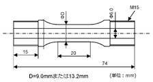
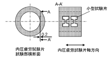
- FIG. 4 is a diagram for explaining a method of examining appropriate ranges for the hardness ratio between the outer surface layer region and the inner surface layer region and the ratio between the outer diameter and the inner diameter of the steel pipe. It is a figure for demonstrating the shape of an internal pressure fatigue test piece.
- FIG. 4 is a diagram for explaining the sampling position and shape of a small dumbbell-shaped test piece;
- residual stress means residual stress in the circumferential direction of the steel pipe.
- cutting in half means cutting the steel pipe so that the steel pipe is divided into two arc-shaped members when viewed from the axial direction.
- the present inventors have conducted research on methods for quantitatively evaluating the residual stress on the inner surface of steel pipes.
- the present inventors considered the residual stress on the outer surface of the steel pipe before and after halving in addition to the residual stress on the inner surface of the steel pipe after halving. It was considered to evaluate the residual stress on the inner surface of the steel pipe.
- the present inventors first performed numerical analysis (FEM analysis) under various conditions using an analytical model of the steel pipe to be evaluated, and calculated the residual stress (calculated value) generated in each part of the steel pipe by self-heating treatment. asked. Specifically, the present inventors first determined, by numerical analysis, the residual stress ⁇ o1 on the outer surface of the steel pipe after self-sealing treatment and before halving, the residual stress on the inner surface of the steel pipe after self-sealing treatment and before halving, ⁇ i1 , the residual stress ⁇ o2 on the outer surface of the steel pipe after self-strength treatment and after halving, and the residual stress ⁇ i2 on the inner surface of the steel pipe after self-strength treatment and after halving were determined.
- FEM analysis numerical analysis
- the present inventors found that the residual stress ⁇ i1 on the inner surface of the steel pipe before halving is equal to the residual stress on the outer surface of the steel pipe before halving. It was found that estimation can be performed with high accuracy using ⁇ o1 , the residual stress ⁇ o2 on the outer surface of the steel pipe after halving, and the residual stress ⁇ i2 on the inner surface of the steel pipe after halving.
- a steel pipe for Pressure Piping and Steel Pipe Material is a steel pipe for pressure piping that has undergone self-tightening treatment.
- Pressure pipes include hydraulic cylinders, airbag steel pipes, accumulators, hydrogen pipes, fuel injection pipes, and the like.
- a steel pipe material according to another embodiment of the present invention is a material for the steel pipe for pressure piping described above, and is used for applications where self-sealing treatment is performed. That is, the steel pipe for pressure piping is obtained by subjecting the steel pipe material to self-heating treatment.
- the average hardness of the outer surface layer region of the steel pipe material is 1.20 times or more the average hardness of the inner surface layer region. The reason for defining in this way will be described later.
- the outer surface layer region refers to a region from the outer surface of the steel pipe material to a depth position of 1/4 of the wall thickness
- the inner surface layer region refers to a region of 1/4 of the wall thickness from the inner surface of the steel pipe material. Refers to the area up to the depth position.
- the outer surface layer region of the steel pipe material By setting the average hardness of the outer surface layer region of the steel pipe material to be 1.20 times or more the average hardness of the inner surface layer region, the outer surface layer region yields when the steel pipe material is subjected to self-tightening treatment. It is possible to apply compressive residual stress by plastically deforming only the inner surface layer region.
- the average hardness of the outer surface layer region of the steel pipe material is preferably 1.50 times or more, more preferably 2.00 times or more, that of the inner surface layer region.
- the average hardness in the outer surface layer region of the steel pipe is 1.2 times or more, preferably 1.5 times or more, more preferably 2.0 times or more, that of the inner surface layer region.
- the outer surface layer region refers to a region from the outer surface of the steel pipe to a depth of 1/4 of the wall thickness
- the inner surface layer region refers to a depth of 1/4 of the wall thickness from the inner surface of the steel pipe. Refers to the area up to the position.
- the average hardness in the inner surface layer region and the outer surface layer region of the steel pipe material or steel pipe is measured as follows. First, in accordance with JIS Z 2244:2009 (Vickers hardness test-testing method), measure the Vickers hardness distribution in the cross section of the steel pipe material or steel pipe.
- the above cross section may be a cross section perpendicular to the axial direction of the steel pipe material or steel pipe, or a cross section parallel to the axial direction and passing through the central axis.
- a general-purpose micro Vickers hardness tester is used as the hardness tester, and the test force is set to 1 to 10N according to the dimensions of the steel pipe. Measurement points are spaced radially from the inner surface to the outer surface by a distance of 1/10 to 1/20 of the wall thickness on the mirror-polished observation surface. When the indentations are close to each other, the measurement positions may be shifted in a direction perpendicular to the radial direction, and measurements may be made at staggered positions. From the hardness distribution thus obtained, the average hardness in the inner surface layer region and the outer surface layer region is obtained by averaging the hardness values included in the inner surface layer region and the outer surface layer region.
- hardening treatment there are no particular restrictions on the method of increasing the average hardness in the outer surface layer region of the steel pipe material (hereinafter also referred to as "hardening treatment").
- hardening treatment there is a method in which induction hardening is performed from the outer surface side of the steel pipe material.
- induction hardening is performed from the outer surface side of the steel pipe material.
- the steel pipe material after induction hardening may be tempered by holding at 100 to 300° C. for 30 minutes or longer and then air cooling.
- the steel pipe When using a steel pipe as an airbag inflator, the steel pipe preferably has an outer diameter of 20 to 100 mm, more preferably 20 to 60 mm.
- the wall thickness of the steel pipe is desirably 1 to 5 mm, more desirably 1 to 4 mm.
- the steel pipe When using a steel pipe as an accumulator, the steel pipe preferably has an outer diameter of 25 to 500 mm, more preferably 50 to 400 mm.
- the wall thickness of the steel pipe is desirably 2-40 mm, more desirably 4-30 mm.
- the inner diameter of the steel pipe is desirably 2.5 mm or more, and more desirably 3.0 mm or more.
- the wall thickness of the steel pipe is desirably 1.5 mm or more, and more desirably 2.0 mm or more.
- the outer diameter of the steel pipe is desirably 20 mm or less, more desirably 15 mm or less, and even more desirably 10 mm or less.
- the mechanical properties they can be selected according to the application, and there is no need to set any particular restrictions.
- the tensile strength of the steel pipe material before hardening treatment, or the tensile strength in the inner surface layer region of the steel pipe after hardening treatment and subsequent self-hardening treatment is preferably 500 MPa or more. , more preferably 600 MPa or more, more preferably 700 MPa or more.
- the yield stress is preferably 300 MPa or higher, more preferably 360 MPa or higher, and even more preferably 420 MPa or higher.
- the hardness of the steel pipe material before hardening treatment, or the hardness in the inner surface layer region of the steel pipe after hardening treatment and subsequent self-hardening treatment in terms of Vickers hardness, is preferably 150 HV or more, and preferably 180 HV or more. is more preferable, and 220 HV or more is even more preferable.
- the Vickers hardness is 500 HV. preferably less than.
- the yield ratio is preferably 0.50 to 0.95, and more preferably 0.60 or more in order to perform self-strengthening treatment at a higher pressure and obtain a large compressive residual stress. 70 or more is more preferable. Further, in order to introduce compressive residual stress more efficiently in self-stressing treatment at low pressure, the yield ratio is more preferably 0.90 or less, and even more preferably 0.85 or less.
- the mechanical properties of the inner surface layer region of the steel pipe are measured by electrical discharge machining of a dumbbell-shaped small test piece having a thickness of about 0.2 mm, as shown in Non-Patent Document 1, so as to be in contact with the inner surface of the steel pipe. It can be measured by cutting out by and performing a tensile test.
- the strain measurement in the tensile test is obtained by conversion from the actuator displacement (stroke) of the tensile tester and the length of the parallel portion of the test piece according to the method shown in Non-Patent Document 1.
- gripping portion a region of a certain length from both end faces
- the length of the gripping portion should be determined in consideration of the pressing pressure and the test load so that the test steel pipe does not slip during the test.
- the length of the parallel portion should be such that the extensometer can be attached and the constriction deformation just before fracture is not affected by the chuck. Even if the steel pipe does not have a straight pipe portion of sufficient length, a thin dumbbell-shaped small test piece as shown in Non-Patent Document 1 may be cut out and subjected to a tensile test.
- the steel pipe for pressure piping preferably has a limit internal pressure that satisfies the following formula (I).
- IP ⁇ 0.44 ⁇ TS ⁇ (I) ⁇ [(D/d) 2 ⁇ 1]/[0.776 ⁇ (D/d) 2 ] (II)
- IP in the above formula (I) means the limit internal pressure (MPa) of the steel pipe
- TS means the inner surface layer region of the steel pipe or the tensile strength (MPa) of the steel pipe material
- ⁇ is expressed by the above formula (II).
- is the value to be D in the above formula (II) is the outer diameter (mm) of the steel pipe
- d is the inner diameter (mm).
- ⁇ is a coefficient for correcting the change in the relationship between the internal pressure and the stress generated on the inner surface of the pipe due to the ratio of the outer diameter to the inner diameter of the pipe.
- the limit internal pressure means that the minimum internal pressure is set to 18 MPa in the internal pressure fatigue test, and a cyclic internal pressure fluctuation with a sine wave is given with respect to time. means the highest internal pressure (MPa) that does not occur. Specifically, on the SN diagram with the maximum internal pressure on the vertical axis and the number of repetitions of damage on the horizontal axis, the minimum value of the maximum internal pressure at which damage occurred and the number of times that damage did not occur even after 10 7 times The median value between the maximum values is taken as the limit internal pressure.
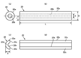
- FIG. 1 is a diagram showing an example of a steel pipe after self-heating treatment whose residual stress is estimated by this model.
- (a) is a left side view of a steel pipe 20 subjected to self-sealing treatment
- (b) is a front view of the steel pipe 20 shown in (a)
- (c) is a )
- (d) is a front view of the halved sample 22 shown in (c).
- the steel pipe after halving means a halved sample obtained by cutting a steel pipe after self-heating treatment into halves.
- the measured values of the residual stress ⁇ o1 on the outer surface 20a of the steel pipe 20 after self-heating treatment, the residual stress ⁇ o2 on the outer surface 22a of the halved sample 22, and the residual stress ⁇ i2 on the inner surface 22b of the halved sample 22 are use.
- the residual stress means the residual stress in the circumferential direction of the steel pipe 20 .
- the length L of the steel pipe 20 when measuring the residual stress is preferably three times or more the outer diameter D of the steel pipe 20, and can be, for example, about 30 mm.
- the steel pipe 20 is cut in half, excessive heat generated due to the cutting affects the residual stress on the inner surface. For this reason, it is necessary to adopt a cutting method that generates as little heat as possible, and it is preferable to cut in half by wire-cut electrical discharge machining.
- the distance X between the cut surface 22c of the halved sample 22 and the center of the outer surface 22a is ⁇ 5 of the radius r of the steel pipe 20. Control so that it is within the range of %.
- the measurement of the residual stress is performed after removing the outer surface 20a of the steel pipe 20 and the inner surface 22b of the halved sample 22 by electropolishing in a range of 10 ⁇ m or less.
- the sin 2 ⁇ method by X-ray diffraction can be used, and the measurement can be performed in conformity with Non-Patent Document 2.
- An estimated value of the residual stress ⁇ i1 is calculated using the residual stresses ⁇ o1 , ⁇ o2 , ⁇ i2 actually measured by the above method, and a multivariable function with the outer diameter D and the inner diameter d as variables.
- an arc-shaped analytical model 40 (1/4 model). Although illustration is omitted, the analysis model 40 is divided into a plurality of elements (mesh). Assume that the physical property value of the analysis model 40 is an elastic body.
- constraint conditions are set so as to restrict the circumferential movement of both ends 40a and 40b of the analysis model 40 in the circumferential direction.
- a body force that simulates the state of the steel pipe 20 during self-heating is set.
- the inner surface 40c of the analysis model 40 is given a circumferential compressive residual stress (-100 MPa).
- FIG. 2(b) and FIGS. 3 and 4, which will be described later, show the state of stress at the end portion 40b.
- the distance in the radial direction between the point P1 at which the compressive stress becomes zero on the end portion 40b and the inner surface 40c is referred to as the distance t
- the thickness of the analysis model 40 is referred to as the thickness T. If there are a plurality of points where the compressive stress becomes 0 on the end portion 40b, one point closer to the inner surface 40c is designated as P1.
- an elastic analysis is performed to redistribute the stresses.
- the position where the stress is 0 is indicated by a dashed line.
- a circumferential compressive stress is generated in the area inside the dashed line, and a circumferential tensile stress is generated in the area outside the dashed line.
- the integrated value of the stress distribution of the entire analysis model 40 is zero.
- the stress state shown in FIG. 3 corresponds to the stress state of the steel pipe 20 after self-heating treatment. Then, in the state shown in FIG.
- the stress at the intersection of the inner surface 40c and the end portion 40b is obtained as the residual stress ⁇ i1 of the inner surface 20b of the steel pipe 20 after self-stressing treatment, and the intersection point of the outer surface 40d and the end portion 40b is is obtained as the residual stress ⁇ o1 of the outer surface 20a of the steel pipe 20 after the self-heating treatment.
- FIG. 4 In order to simulate the halved sample 22 (steel pipe 20 after halving), as shown in FIG. This further changes the stress state of the analytical model 40 .
- the position where the stress is 0 is indicated by a dashed line.
- tensile stress in the circumferential direction is generated in the central portion in the radial direction.
- directional compressive stress is generated.
- the end portion 40a corresponds to the cut surface 22c (see FIG. 1) of the half-divided sample 22
- the end portion 40b corresponds to the central portion 22d (see FIG. 1) of the half-divided sample 22 in the circumferential direction. reference).
- (t/T) can be expressed by the following formula (3).
- t/T ((B ⁇ ( ⁇ o2 ⁇ o1 ) ⁇ E ⁇ i2 )/(A ⁇ ( ⁇ o2 ⁇ o1 ) ⁇ C ⁇ i2 )) 1/2 (3)
- B is set to 1 and E is set to 0 to obtain the following formula (ii).
- the estimated value ⁇ i1 of the residual stress of the inner surface 20b of the steel pipe 20 after self-heating treatment can be calculated from the equations (i) to (iv) obtained from the above estimation model.
- the steel pipe according to the present invention has a value of ⁇ i1 of ⁇ 150 MPa or less. If the compressive residual stress exceeds ⁇ 150 MPa, that is, if the absolute value of the residual stress is less than 150 MPa, the effect of improving the critical internal pressure cannot be obtained, as shown in the examples below.
- a high limit internal pressure can be obtained by setting ⁇ i1 to ⁇ 150 MPa or less by self-tightening treatment.
- the object of analysis is the steel pipe shape shown in Fig. 1, and the 1/4 cylindrical analysis model with the three-dimensional hexahedral secondary element shown in Fig. 5(a) was used for FEM analysis.
- the physical property values of the model were elastoplastic.
- the Young's modulus in the elastic region was 205.8 GPa, the Poisson's ratio was 0.3, and in the elasto-plastic region, a stress-strain curve was used based on true stress and true plastic strain shown in FIG.
- the kinematic hardening rule was used for the hardening rule of the elastoplastic region.
- different stress-strain curves were set in the analytical model according to the hardness distribution depending on the radial position. There are three types of Hvo/Hvi: 1.00, 1.20 and 1.75.
- a radial stress ⁇ r corresponding to the internal pressure P is applied to the inner surface of the model, and an axial stress ⁇ ax is applied to the cross section of the model.
- ⁇ r and ⁇ ax are given by the following equations using the inner diameter d.
- ⁇ r ⁇ P (4)
- ⁇ ax P ⁇ d 2 /(D 2 ⁇ d 2 ) (5)
- the above formula (5) is a basic formula relating to the cylindrical container, and is based on the following concept. Assuming that the object of analysis is a member with a closed cross section, an axial load P ⁇ d 2 /4 is generated by the internal pressure acting on the inner cross section of the model. Since this axial load acts on the model cross-section, the axial stress ⁇ ax is obtained by dividing the axial load by the cross-sectional area of the model cross-section ⁇ (D 2 -d 2 )/4.
- ⁇ r and ⁇ ax corresponding to internal pressures of 0.60, 0.70, and 0.85 times the burst strength were applied to the model and unloaded.
- the residual stress in the circumferential direction of the inner surface after unloading is output, and the minimum value (basically the compressive residual stress, so the absolute value is the maximum value) is taken as the representative value of the residual stress introduced by the self-straining process. did.
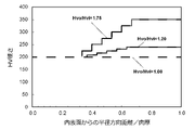
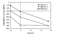
- Hvo/Hvi is shown in FIG. 8, and the relationship with D/d is shown in FIG.
- D/d is 1.2
- Hvo/Hvi is 1.20 or more
- the compressive residual stress of the inner surface is -150 MPa or more.
- D/d is 1.8
- the compressive residual stress does not change when Hvo/Hvi is 1.20 or more.
- the ratio Hvo/Hvi of the average hardness Hvo in the outer surface layer region and the average hardness Hvi in the inner surface layer region of the hardened steel pipe material should be 1.20 times or more, and the outer diameter D and the inner diameter d of the steel pipe material A ratio D/d of 2.0 or less was defined as an appropriate range.
- the method for manufacturing the steel pipe for pressure piping according to the present invention is not particularly limited. On the other hand, it is possible to manufacture steel pipes by carrying out self-cooling treatment under various conditions, obtaining ⁇ i1 for each steel pipe obtained by the above-described method, and selecting steel pipes with ⁇ 150 MPa or less.
- the self-cooling treatment conditions can be adjusted so that ⁇ i1 is ⁇ 150 MPa or less, for example, by controlling the self-cooling treatment pressure and/or the self-cooling treatment time. As described above, by accurately estimating the residual stress on the inner surface of the steel pipe after self-heating and before halving, it is possible to optimize the self-heating conditions and stably obtain a steel pipe having a high critical internal pressure. It becomes possible.
- the shape after rough machining has an outer diameter larger by 1 mm and an inner diameter smaller by 1 mm than the shape after finishing shown in FIG. Note that the unit of length shown in FIG. 10 is mm.
- Test No. Test Nos. 1 to 3 were used as they were (standardized product).
- induction hardening and tempering were performed by further heating the outer surface to 1000°C instantaneously by high-frequency heating, immediately quenching, then heating to 150°C, holding for 1 hour, and air cooling ( hardened). Then, final finishing was performed, and the inner and outer surfaces of the test portion were polished.
- the test piece shape of FIG. 1, 2, and 4 to 6 have an outer diameter of 9.0 mm (D/d: 1.5).
- the outer diameters of 3 and 7 are 13.2 mm (D/d: 2.2).
- test No. 2, 3, and 5 to 7 specimens were subjected to self-stress treatment at the pressures shown in Table 2.
- Self-tightening treatment was carried out by sealing one side end face of the internal pressure fatigue test piece of FIG. 10, enclosing working oil as a pressure medium inside the test piece from the other side end face, and controlling the internal pressure of the enclosed portion.
- the self-containment treatment is carried out by increasing the internal pressure of the enclosure to the self-containment treatment pressure and removing the load.
- test pieces were prepared for each of the above, and using one test piece, the average hardness of the outer surface layer region and the inner surface layer region was measured, and the tensile test of the inner surface layer region was performed.
- a parallel cross-section passing through the central axis is cut out from the test piece, embedded in resin so that this cross-section becomes the observation surface, and mirror-polished with emery paper and a buff. rice field.
- a general-purpose micro Vickers hardness tester was used as the hardness tester, and the test force was set to 3N. The measurement was performed radially from the inner surface to the outer surface on the observation surface at a pitch of 0.1 mm. That is, the measurement points are the test No.
- the hardness of the inner surface layer region of 4 to 7 was within the range of 196 to 205 HV, and no change was observed depending on the presence or absence of hardening treatment and the presence or absence of self-tightening treatment.
- Test no. The hardness of the outer surface layer region of 4 to 7 was 433 to 445 HV, and Hvo/Hvi was 2.17 to 2.24.
- a dumbbell-shaped small test piece with a thickness of about 0.2 mm was placed on the inner surface of the internal pressure fatigue test piece test portion from the inner surface layer region of the internal pressure fatigue test piece test portion. Two pieces were cut out by electrical discharge machining so as to be in contact with each other, and were used. Tytron 250 manufactured by MTS was used as a tensile tester. The strain measurement was obtained by conversion from the actuator displacement (stroke) of the tensile tester and the length of the parallel portion of the test piece according to the method shown in Non-Patent Document 1. In the stress-strain curve thus obtained, the 0.2% proof stress was defined as the yield stress, the maximum stress was defined as the tensile strength, and the average value of two small test pieces was used as the measured value.
- Test No. In the inner surface layer region of 1 to 7, the tensile strength was 621 to 632 MPa, the yield stress was 382 to 391 MPa, and the yield ratio was 0.61 to 0.62. .
- the circumferential residual stress ⁇ o1 is measured after removing the outer surface layer of the test piece at the central position in the longitudinal direction by electropolishing in a range of 10 ⁇ m or less.
- the sin 2 ⁇ method by X-ray diffraction was used, and the measurement was carried out in conformity with Non-Patent Document 2.
- Detailed measurement conditions are as follows.
- ⁇ Scanning method side tilt method, constant ⁇ method (PSPC method)
- PSPC-RSF constant ⁇ method
- X-ray stress measurement device PSPC-RSF manufactured by Rigaku Corporation
- ⁇ Characteristic X-ray Crk ⁇
- ⁇ Measurement diffraction plane ⁇ -Fe211
- Incoming slit single collimator, diameter 0.3 mm - Incident angle ( ⁇ ): 0°, 12.9°, 18.5°, 22.8°, 26.6°, 30.0°, 33.3°, 36.3°, 39.3°
- Diffraction angle determination method half width method
- ⁇ Stress constant (K) -318 MPa / °
- test piece for which the residual stress on the outer surface was measured was cut in half along the tube axis by wire-cut electrical discharge machining.
- the cutting position was around ⁇ 90° when the outer surface residual stress measurement position was set at 0° in the circumferential direction.
- the thickness t between the cut surface of each sample after halving and the outer surface at the central position in the longitudinal direction was in the range of D/2 ⁇ 0.2 mm.
- the circumferential residual stress ⁇ o2 of the sample after halving was measured again at the outer surface residual stress measurement position before halving. Furthermore, after removing the inner surface layer of the inner surface at the center position in the longitudinal direction of the test piece in a range of 10 ⁇ m or less by electropolishing after halving, the circumferential residual stress ⁇ i2 at the center position of the inner surface of the pipe was measured.
- Table 2 shows the measured residual stress values ⁇ o1 , ⁇ o2 , and ⁇ i2 thus obtained.
- the internal pressure fatigue test was performed on the remaining test pieces to clarify the critical internal pressure.
- the internal pressure is repeatedly varied from the maximum internal pressure to the minimum of 18 MPa in a sine wave with respect to time.
- the frequency of internal pressure fluctuation was set to 8 Hz.
- the maximum internal pressure at which breakage (leakage) did not occur even after 10 7 cycles was evaluated as the critical internal pressure.
- the results are also shown in Table 2.
- test No. 1 and test no. 2 test no. In 2, since the hardness ratio was not set to 1.20 or more without performing hardening treatment, sufficient compressive stress was not applied even though self-tightening treatment was performed, and test No. in which self-tightening treatment was not performed . 1, the limit internal pressure could not be improved.
- test No. 3 is a comparative example in which the hardness ratio does not satisfy the stipulations of the present invention, but since D/d is as high as 2.2, residual stress is sufficiently imparted by self-stressing treatment, and the limit internal pressure is improved. This resulted in Also, test no. 7, test no. D/d was the same as that of Test No. 3, and the hardness of the outer surface layer region was increased. 3 was equivalent. For this reason, test No. 7 and test no. 3 was equivalent.
- the steel pipe for pressure piping according to the present invention can be suitably used particularly as hydraulic cylinders, airbag steel pipes, accumulators, hydrogen pipes, fuel injection pipes and the like.
Landscapes
- Chemical & Material Sciences (AREA)
- Engineering & Computer Science (AREA)
- Mechanical Engineering (AREA)
- Organic Chemistry (AREA)
- Materials Engineering (AREA)
- Metallurgy (AREA)
- General Engineering & Computer Science (AREA)
- Crystallography & Structural Chemistry (AREA)
- Physics & Mathematics (AREA)
- Thermal Sciences (AREA)
- Combustion & Propulsion (AREA)
- Manufacturing & Machinery (AREA)
- Investigating Strength Of Materials By Application Of Mechanical Stress (AREA)
- Heat Treatment Of Articles (AREA)
Priority Applications (5)
| Application Number | Priority Date | Filing Date | Title |
|---|---|---|---|
| CN202280013425.9A CN116829862A (zh) | 2021-02-04 | 2022-01-07 | 压力配管用钢管及钢管坯料 |
| EP22749409.3A EP4290107A1 (en) | 2021-02-04 | 2022-01-07 | Pressure piping steel pipe and steel pipe material |
| KR1020237024511A KR20230119233A (ko) | 2021-02-04 | 2022-01-07 | 압력 배관용 강관 및 강관 소재 |
| US18/256,577 US20240093324A1 (en) | 2021-02-04 | 2022-01-07 | Steel pipe for pressure piping and starting material for steel pipe |
| JP2022579399A JPWO2022168530A1 (zh) | 2021-02-04 | 2022-01-07 |
Applications Claiming Priority (2)
| Application Number | Priority Date | Filing Date | Title |
|---|---|---|---|
| JP2021-016940 | 2021-02-04 | ||
| JP2021016940 | 2021-02-04 |
Publications (1)
| Publication Number | Publication Date |
|---|---|
| WO2022168530A1 true WO2022168530A1 (ja) | 2022-08-11 |
Family
ID=82742328
Family Applications (1)
| Application Number | Title | Priority Date | Filing Date |
|---|---|---|---|
| PCT/JP2022/000422 WO2022168530A1 (ja) | 2021-02-04 | 2022-01-07 | 圧力配管用鋼管および鋼管素材 |
Country Status (6)
| Country | Link |
|---|---|
| US (1) | US20240093324A1 (zh) |
| EP (1) | EP4290107A1 (zh) |
| JP (1) | JPWO2022168530A1 (zh) |
| KR (1) | KR20230119233A (zh) |
| CN (1) | CN116829862A (zh) |
| WO (1) | WO2022168530A1 (zh) |
Cited By (1)
| Publication number | Priority date | Publication date | Assignee | Title |
|---|---|---|---|---|
| EP4134578A4 (en) * | 2020-04-07 | 2023-09-20 | Nippon Steel Corporation | STEEL PIPE FOR PRESSURE PIPES |
Citations (6)
| Publication number | Priority date | Publication date | Assignee | Title |
|---|---|---|---|---|
| JPS61283415A (ja) * | 1985-06-07 | 1986-12-13 | Kawasaki Heavy Ind Ltd | 耐摩耗二重管の製造方法 |
| JPH04183820A (ja) | 1990-11-19 | 1992-06-30 | Nippon Steel Corp | 内圧疲労特性の優れたシリンダーチューブ用鋼管の製造方法 |
| JP2004092551A (ja) * | 2002-09-02 | 2004-03-25 | Usui Kokusai Sangyo Kaisha Ltd | ディーゼルエンジン用コモンレール |
| JP2005201254A (ja) * | 2003-12-16 | 2005-07-28 | Usui Kokusai Sangyo Kaisha Ltd | ディーゼルエンジン用高圧燃料配管 |
| US20150183015A1 (en) * | 2009-08-17 | 2015-07-02 | Ati Properties, Inc. | Method of Producing Cold-Worked Centrifugal Cast Tubular Products |
| WO2016203924A1 (ja) * | 2015-06-17 | 2016-12-22 | 臼井国際産業株式会社 | 燃料噴射管用鋼管およびその製造方法 |
-
2022
- 2022-01-07 WO PCT/JP2022/000422 patent/WO2022168530A1/ja active Application Filing
- 2022-01-07 KR KR1020237024511A patent/KR20230119233A/ko unknown
- 2022-01-07 US US18/256,577 patent/US20240093324A1/en active Pending
- 2022-01-07 JP JP2022579399A patent/JPWO2022168530A1/ja active Pending
- 2022-01-07 CN CN202280013425.9A patent/CN116829862A/zh active Pending
- 2022-01-07 EP EP22749409.3A patent/EP4290107A1/en active Pending
Patent Citations (6)
| Publication number | Priority date | Publication date | Assignee | Title |
|---|---|---|---|---|
| JPS61283415A (ja) * | 1985-06-07 | 1986-12-13 | Kawasaki Heavy Ind Ltd | 耐摩耗二重管の製造方法 |
| JPH04183820A (ja) | 1990-11-19 | 1992-06-30 | Nippon Steel Corp | 内圧疲労特性の優れたシリンダーチューブ用鋼管の製造方法 |
| JP2004092551A (ja) * | 2002-09-02 | 2004-03-25 | Usui Kokusai Sangyo Kaisha Ltd | ディーゼルエンジン用コモンレール |
| JP2005201254A (ja) * | 2003-12-16 | 2005-07-28 | Usui Kokusai Sangyo Kaisha Ltd | ディーゼルエンジン用高圧燃料配管 |
| US20150183015A1 (en) * | 2009-08-17 | 2015-07-02 | Ati Properties, Inc. | Method of Producing Cold-Worked Centrifugal Cast Tubular Products |
| WO2016203924A1 (ja) * | 2015-06-17 | 2016-12-22 | 臼井国際産業株式会社 | 燃料噴射管用鋼管およびその製造方法 |
Non-Patent Citations (2)
| Title |
|---|
| "Standard for X-Ray Stress Measurement (2002) - Iron and Steel", THE SOCIETY OF MATERIALS SCIENCE, March 2002 (2002-03-01) |
| EISUKE NAKAYAMAMITSUO MIYAHARAKAZUO OKAMURAHIROKI FUJIMOTOKIYOYUKI FUKUI: "Prediction of Fatigue Strength of Spot-Welded Joints Based on Local Material Strength Properties Measured by Small Specimen", J.SOC, MAT. SCI., vol. 53, no. 10, October 2004 (2004-10-01), pages 1136 - 1142 |
Cited By (1)
| Publication number | Priority date | Publication date | Assignee | Title |
|---|---|---|---|---|
| EP4134578A4 (en) * | 2020-04-07 | 2023-09-20 | Nippon Steel Corporation | STEEL PIPE FOR PRESSURE PIPES |
Also Published As
| Publication number | Publication date |
|---|---|
| JPWO2022168530A1 (zh) | 2022-08-11 |
| KR20230119233A (ko) | 2023-08-16 |
| US20240093324A1 (en) | 2024-03-21 |
| EP4290107A1 (en) | 2023-12-13 |
| CN116829862A (zh) | 2023-09-29 |
Similar Documents
| Publication | Publication Date | Title |
|---|---|---|
| WO2022168530A1 (ja) | 圧力配管用鋼管および鋼管素材 | |
| Závodská et al. | Fatigue resistance of low alloy steel after shot peening | |
| Kucharska et al. | Mechanical and microstructural aspects of C20-steel blades subjected to gas nitriding | |
| Jiang et al. | Constitutive modelling of AISI 9310 alloy steel and numerical calculation of residual stress after shot peening | |
| Maqbool et al. | Experimental investigation and finite element modelling of residual stress control in disc springs made of metastable austenitic stainless steel (MASS) using incremental sheet forming (ISF) | |
| Hu et al. | Computer modeling and optimization of swage autofrettage process of a thick-walled cylinder incorporating bauschinger effect | |
| Burns et al. | Paper 28: Effect of Mean Shear Stress on the Fatigue Behaviour of Thick-Walled Cylinders | |
| Žagar et al. | Surface modification analysis after shot peening of AA 7075 in different states | |
| Benaissa et al. | The effects of shot peening on the surface characteristics of 35NCD16 alloy steel | |
| Gerin et al. | Effect of cold forming on the high cycle fatigue behaviour of a 27MnCr5 steel | |
| Seemikeri et al. | Improvements in surface integrity and fatigue life of low plasticity burnished surfaces | |
| EP4134578A1 (en) | Steel pipe for pressure piping | |
| Müller et al. | Calculation of sub-surface-initiated fatigue fractures in gears | |
| Necpal et al. | Evaluation of material deformation during process of precise carbon steel tube cold draw forming | |
| Jayaraman et al. | LPB as a Crack Initiation Resistant Process for Case Hardened Steels | |
| Yoon et al. | Low cycle fatigue testing of 429EM stainless steel pipe | |
| Ammerlaan et al. | Relationship Between Deep Case Carburizing and Residual Stress in Rolling Contact Service | |
| Kadhim et al. | Mechanical properties of burnished steel AISI 1008 | |
| Kumar et al. | Specimen geometry and its effect on flow curve in torsion testing–A review | |
| Di Graci Tiralongo et al. | Model for microhardness profile prediction of annealed AISI 1045 steel cylindrical bars subjected to torsion | |
| Maximov et al. | Direct correlation between surface integrity and fatigue limit of surface cold worked chromium-nickel austenitic stainless steels | |
| Elsamanty et al. | Investigating the Impact of Tool Type on Optimizing Burnishing Parameters for AISI 1035 Steel: A Taguchi and RSM Approach | |
| Puntambekar et al. | Correlation of Effect of Plasma-Nitridingon Fatigue Life of Low-Alloy Steel with Surface Stresses Estimated using FEM Analysis | |
| Sharma et al. | Effect of Barrel Radius on the Billet in the Upsetting Process | |
| Lenzen et al. | Characterization and Modelling of Sheet Material with Graded Strength for more Accurate Finite Element Analysis |
Legal Events
| Date | Code | Title | Description |
|---|---|---|---|
| 121 | Ep: the epo has been informed by wipo that ep was designated in this application |
Ref document number: 22749409 Country of ref document: EP Kind code of ref document: A1 |
|
| ENP | Entry into the national phase |
Ref document number: 2022579399 Country of ref document: JP Kind code of ref document: A |
|
| WWE | Wipo information: entry into national phase |
Ref document number: 18256577 Country of ref document: US |
|
| REG | Reference to national code |
Ref country code: BR Ref legal event code: B01A Ref document number: 112023010723 Country of ref document: BR |
|
| ENP | Entry into the national phase |
Ref document number: 20237024511 Country of ref document: KR Kind code of ref document: A |
|
| WWE | Wipo information: entry into national phase |
Ref document number: 202280013425.9 Country of ref document: CN |
|
| WWE | Wipo information: entry into national phase |
Ref document number: 2023116017 Country of ref document: RU |
|
| ENP | Entry into the national phase |
Ref document number: 112023010723 Country of ref document: BR Kind code of ref document: A2 Effective date: 20230531 |
|
| NENP | Non-entry into the national phase |
Ref country code: DE |
|
| ENP | Entry into the national phase |
Ref document number: 2022749409 Country of ref document: EP Effective date: 20230904 |