WO2022168331A1 - 操作ログ生成装置および操作ログ生成方法 - Google Patents
操作ログ生成装置および操作ログ生成方法 Download PDFInfo
- Publication number
- WO2022168331A1 WO2022168331A1 PCT/JP2021/004679 JP2021004679W WO2022168331A1 WO 2022168331 A1 WO2022168331 A1 WO 2022168331A1 JP 2021004679 W JP2021004679 W JP 2021004679W WO 2022168331 A1 WO2022168331 A1 WO 2022168331A1
- Authority
- WO
- WIPO (PCT)
- Prior art keywords
- image
- images
- unit
- operation event
- operation log
- Prior art date
- Legal status (The legal status is an assumption and is not a legal conclusion. Google has not performed a legal analysis and makes no representation as to the accuracy of the status listed.)
- Ceased
Links
Images



Classifications
-
- G—PHYSICS
- G06—COMPUTING OR CALCULATING; COUNTING
- G06V—IMAGE OR VIDEO RECOGNITION OR UNDERSTANDING
- G06V10/00—Arrangements for image or video recognition or understanding
- G06V10/70—Arrangements for image or video recognition or understanding using pattern recognition or machine learning
- G06V10/762—Arrangements for image or video recognition or understanding using pattern recognition or machine learning using clustering, e.g. of similar faces in social networks
-
- G—PHYSICS
- G06—COMPUTING OR CALCULATING; COUNTING
- G06F—ELECTRIC DIGITAL DATA PROCESSING
- G06F11/00—Error detection; Error correction; Monitoring
- G06F11/30—Monitoring
- G06F11/34—Recording or statistical evaluation of computer activity, e.g. of down time, of input/output operation ; Recording or statistical evaluation of user activity, e.g. usability assessment
-
- G—PHYSICS
- G06—COMPUTING OR CALCULATING; COUNTING
- G06V—IMAGE OR VIDEO RECOGNITION OR UNDERSTANDING
- G06V10/00—Arrangements for image or video recognition or understanding
- G06V10/70—Arrangements for image or video recognition or understanding using pattern recognition or machine learning
- G06V10/74—Image or video pattern matching; Proximity measures in feature spaces
- G06V10/761—Proximity, similarity or dissimilarity measures
-
- G—PHYSICS
- G06—COMPUTING OR CALCULATING; COUNTING
- G06V—IMAGE OR VIDEO RECOGNITION OR UNDERSTANDING
- G06V10/00—Arrangements for image or video recognition or understanding
- G06V10/70—Arrangements for image or video recognition or understanding using pattern recognition or machine learning
- G06V10/764—Arrangements for image or video recognition or understanding using pattern recognition or machine learning using classification, e.g. of video objects
-
- G—PHYSICS
- G06—COMPUTING OR CALCULATING; COUNTING
- G06V—IMAGE OR VIDEO RECOGNITION OR UNDERSTANDING
- G06V20/00—Scenes; Scene-specific elements
- G06V20/30—Scenes; Scene-specific elements in albums, collections or shared content, e.g. social network photos or video
Definitions
- the present invention relates to an operation log generation device and an operation log generation method.
- the application is not installed on the terminal where the user actually operates (hereinafter referred to as the client terminal), but the application is installed on another terminal (server) connected to the client terminal, and the client terminal An operation screen provided by the application is displayed as an image, and the user operates the application on the server side through the displayed image.
- the operation screen is displayed as an image on the terminal where the user actually operates, it is impossible to acquire the attribute values of the GUI components described above from the client terminal.
- the present invention has been made in view of the above, and is intended to universally specify the type of operation required to generate an operation log for operations performed on a GUI application regardless of the execution environment of the target application. aim.
- an operation log generation device includes an acquisition unit that detects a user's operation event and acquires the position where the operation event occurs in the captured image of the operation screen.
- a specifying unit that specifies an image at a position where the operation event occurs from among the images that are candidates for the GUI component extracted from the captured image, and records the image and the operation event in association with each other;
- a classifying unit that classifies a set of images into clusters according to the degree of similarity between the images; and a generating unit that generates an operation log using an image corresponding to the operation event in each classified cluster. It is characterized by
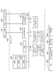
- FIG. 1 is a schematic diagram illustrating a schematic configuration of an operation log generation device according to this embodiment.
- FIG. 2 is a diagram for explaining the processing of the specifying unit;
- FIG. 3 is a diagram for explaining the processing of the specifying unit;
- FIG. 4 is a diagram for explaining the processing of the specifying unit;
- FIG. 5 is a flow chart showing an operation log generation processing procedure.
- FIG. 6 is a diagram illustrating an example of a computer that executes an operation log generation program;
- FIG. 1 is a schematic diagram illustrating a schematic configuration of an operation log generation device according to this embodiment.
- the operation log generation device 10 of this embodiment is realized by a general-purpose computer such as a personal computer or a workstation, and includes an input unit 11, an output unit 12, a communication control unit 13, a storage unit 14, and a control unit. 15.
- the input unit 11 is implemented using input devices such as a keyboard and a mouse, and inputs various instruction information such as processing start to the control unit 15 in response to input operations by the operator.
- the output unit 12 is implemented by a display device such as a liquid crystal display, a printing device such as a printer, or the like. For example, the output unit 12 displays the result of operation log generation processing, which will be described later.
- the communication control unit 13 is realized by a NIC (Network Interface Card) or the like, and controls communication between an external device and the control unit 15 via an electrical communication line such as a LAN (Local Area Network) or the Internet.
- the communication control unit 13 controls communication between a terminal or the like operated by the user and the control unit 15 .
- this terminal may be implemented in the same hardware as the operation log generation device 10 .
- the storage unit 14 is implemented by semiconductor memory devices such as RAM (Random Access Memory) and flash memory, or storage devices such as hard disks and optical disks.
- the storage unit 14 pre-stores a processing program that causes the operation log generation device 10 to operate, data that is used during execution of the processing program, or the like, or temporarily stores the data each time processing is performed.
- the storage unit 14 also stores an operation log 14a that is the result of operation log generation processing, which will be described later. Note that the storage unit 14 may be configured to communicate with the control unit 15 via the communication control unit 13 .
- the control unit 15 is implemented using a CPU (Central Processing Unit) or the like, and executes a processing program stored in memory. Thereby, the control unit 15 functions as an acquisition unit 15a, an identification unit 15b, a classification unit 15c, and a generation unit 15d, as illustrated in FIG. Note that these functional units may be implemented in different hardware, respectively or partially. Also, the control unit 15 may include other functional units.
- a CPU Central Processing Unit
- the acquisition unit 15a detects a user's operation event such as a user's mouse click or keyboard input, and acquires the occurrence position of the operation event in the captured image of the operation screen. Specifically, the acquiring unit 15a periodically acquires a captured image of the user's operation screen. It also monitors the occurrence of operation events.
- a user's operation event such as a user's mouse click or keyboard input
- the acquisition unit 15a compares the captured images of the operation screen immediately before and after the operation event. Then, when a change occurs in the captured image, the acquisition unit 15a acquires the position where the change occurs as the occurrence position of the operation event on the operation screen. Thereby, the acquisition unit 15a can acquire the occurrence position of the operation event that has occurred with respect to the operable GUI component.
- the acquisition unit 15a has a function of detecting the occurrence of an operation event such as a keyboard input or a mouse click, and when an operation event is detected, captures the operation event occurrence time, the operation event occurrence position, and the operation screen immediately before the operation event occurs. It has a function of notifying the specifying unit 15b, which will be described later, of the image.
- a captured image of the operation screen immediately before the operation event occurs can be obtained, for example, by periodically acquiring an image capture and comparing it with the event occurrence time.
- the acquisition unit 15a can detect the occurrence of an operation event by using a global hook in the case of Windows (registered trademark) OS, for example. Similarly, the acquisition unit 15a can acquire the event occurrence position by a global hook, for example, if it is a mouse click.
- the acquisition unit 15a acquires the position where the operation event has occurred.
- keyboard input since keyboard input usually involves the input of a character string, it is possible to specify the position where the operation event occurs by comparing captured images before and after the occurrence of the operation event. Accordingly, the acquisition unit 15a can reliably detect an operation event that causes a change in the screen. It should be noted that the change occurs not at one point, but over a wide area, but any coordinates included there can be used.
- Keyboard input includes operations that do not involve input, such as the Tab key, direction keys, and shift keys, but since these are often meaningless in analysis, they are ignored in this embodiment.
- the acquisition unit 15a may acquire and record information about the type of operation event (mouse click, keyboard input).
- the acquisition unit 15a may compare the captured image of the entire operation screen, or compare the image around the position where the operation event occurs. You may
- the specifying unit 15b specifies the image at the position where the operation event occurs among the images that are candidates for the GUI component extracted from the captured image by the process described later, and records the image and the operation event in association with each other. Specifically, the specifying unit 15b extracts an image that is a candidate for a GUI component from the acquired captured image immediately before the occurrence of the operation event, and determines on which image the operation event occurred from the position of occurrence of the operation event. is identified, and operation event information including the position, time and type of operation event occurrence and the image are recorded in association with each other.
- the specifying unit 15b extracts an image that is a candidate for a GUI component of a predetermined format from the acquired captured image using the features of the image.
- the specifying unit 15b uses OpenCV (Open Source Computer Vision Library) or the like to specify edges of GUI parts by using as a feature the difference in color between the area occupied by each GUI part and the other area.
- the identifying unit 15b cuts out a circumscribing rectangle including the edge using the identified edge as a contour, thereby cutting out an image that is a GUI component candidate from the operation image.
- the specifying unit 15b extracts an image that is a candidate for a GUI component by cutting out an image of a predetermined format from the captured image and images around the image.
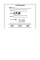
- FIGS. 3(a) to 3(c) illustrate a case where the identification unit 15b extracts images that are candidates for GUI parts from the captured images on the operation screen shown in FIG. 2, and associates them with operation events.
- FIG. 3A an image cut out as an image is exemplified as surrounded by a dashed line.
- FIG. 3B illustrates a case of extracting an image of a text box that can be an image to be operated.
- the specifying unit 15b can distinguish between different text boxes on the same operation screen by cutting out an image including an image around the text box.
- FIG. 3B illustrates a case where the identification unit 15b extracts images that are candidates for GUI parts from the captured images on the operation screen shown in FIG. 2, and associates them with operation events.
- FIG. 3A an image cut out as an image is exemplified as surrounded by a dashed line.
- FIG. 3B illustrates a case of extracting an image of a text box that can be an image to be operated.
- a text box for entering a name and a text box for entering an address are created by clipping an image so as to include character images around the specified text box. It is possible to distinguish between Further, by determining the similarity excluding the common area, the classification unit 15c, which will be described later, can perform classification with higher accuracy.
- the specifying unit 15b specifies an image including the position of occurrence of the operation event from among the extracted images, and extracts the specified image, the position of occurrence of the operation event, the time of occurrence of the operation event, and the type of the operation event. information in association with each other and stored in the storage unit 14 .
- the specifying unit 15b specifies the innermost image among the images including the operation event occurrence position. do. Note that the specifying unit 15b may specify the outermost image among the images including the position where the operation event occurs. That is, the identifying unit 15b only needs to identify one image for each operation event.
- FIG. 4(a) illustrates images (images 1 to 3) cut out from FIG. 3(c).
- FIGS. 4B and 4C exemplify the positions of occurrence of operation events regarded as operations on each image.
- FIG. 4B exemplifies the position of occurrence of an operation event regarded as an operation on image 2 when specifying the outermost image.
- the identifying unit 15b may associate the identified image, the position of occurrence, the type of the operation event, and the time of occurrence, and transfer them to the classifying unit 15c described below without storing them in the storage unit 14. .
- the classification unit 15c classifies the set of recorded images into clusters according to the degree of similarity between the images.
- the purpose of this processing is to classify the same operation type into the same cluster for the operations performed on the GUI.
- the classification unit 15c classifies the images according to the degree of similarity of the display position of each image in the captured image of the operation screen.
- images representing GUI parts displayed at the same position on the operation screen are classified into the same cluster.
- the configuration of the operation screen is fixed, all GUI parts are always displayed in the same position. Therefore, images extracted from GUI parts of the same operation event are classified into the same cluster, that is, the same operation type. It becomes possible to
- the classification unit 15c classifies the images according to the degree of similarity between the images. As a result, images obtained by cutting out GUI parts of the same operation event are classified into the same cluster.
- the configuration of the operation screen changes dynamically, the display position of each GUI component changes, so images cannot be classified based on the similarity of display positions. Therefore, since the GUI parts for the same operation event are the same image, the images are classified by using the degree of similarity on the image. For image similarity determination, similarity determination using, for example, pattern matching and various feature amounts/feature points is possible.
- the classification unit 15c assigns cluster IDs that identify each cluster to the classified clusters. That is, the cluster ID corresponds to the operation type.
- the generation unit 15d generates the operation log 14a using the image corresponding to the operation event of each classified cluster. Specifically, for each operation event, the generation unit 15d records the cluster image in association with the cluster ID and the operation event occurrence time, generates the operation log 14a, and stores the generated operation log 14a in the storage unit 14. Memorize. Further, the generation unit 15d may generate the operation log 14a by associating the operation event type with the image.
- the classifying unit 15c adds an arbitrary character string to the images included in the cluster for each cluster so that the analyst can distinguish the images included in the cluster. , and the flow may be generated using that string. Also, the classification unit 15c can extract a characteristic character string from the images included in the cluster by OCR and assign it as a label.
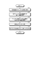
- FIG. 5 is a flowchart showing an operation log generation processing procedure.
- the flowchart of FIG. 5 is started, for example, at the timing when the user performs an operation input instructing the start.
- the acquisition unit 15a periodically acquires a captured image of the user's operation screen (step S1). Further, when the acquisition unit 15a detects a user operation event, the acquisition unit 15a compares the captured images of the operation screen immediately before and after the operation event. (step S2).
- the specifying unit 15b specifies an image at the position where the operation event occurs, among the images that are candidates for the GUI component extracted from the captured image (step S3), and records the image and the operation event in association with each other. do.
- the identifying unit 15b identifies an image that is a candidate for a GUI component of a predetermined format from the captured image using features on the image, and cuts out the identified image from the captured image.
- an image including the operation event occurrence position is specified from among the extracted images, and the specified image is associated with operation event information including the operation event occurrence position, the operation event occurrence time, and the operation event type. is stored in the storage unit 14.
- the classification unit 15c classifies the set of recorded images into clusters according to the degree of similarity between the images (step S4). For example, the classification unit 15c classifies the images according to the degree of similarity of the display position of each image in the captured image. Alternatively, the classification unit 15c classifies the images according to the image similarity of each image.
- the generation unit 15d generates an operation log using images corresponding to operation events of each cluster (step S5). For example, the generation unit 15d records the images included in each classified cluster in association with the cluster ID and the operation event occurrence time, and generates the operation log 14a. Further, the generation unit 15d causes the storage unit 14 to store the generated operation log 14a. Alternatively, the generation unit 15d outputs the operation log 14a to a device that creates an operation flow, for example. This completes a series of operation log generation processing.
- the acquisition unit 15a detects a user's operation event and acquires the occurrence position of the operation event in the captured image of the operation screen.
- the identifying unit 15b identifies the image at the position where the operation event occurs among the images that are candidates for the GUI component extracted from the captured image, and records the image and the operation event in association with each other.
- the classification unit 15c classifies the set of recorded images into clusters according to the degree of similarity between the images.
- the generating unit 15d generates the operation log 14a using the images corresponding to the classified operation events of each cluster.
- the operation log generation device 10 can easily and automatically acquire the operation log 14a of the application, regardless of the type of GUI application, without preparing training data in advance or specifying conditions. It becomes possible.
- the operation log generation device 10 can extract only operation events performed on operable GUI components.
- the acquisition unit 15a acquires the occurrence position of the operation event. Accordingly, the acquisition unit 15a can reliably detect an operation event that causes a change in the screen, and extract only an operation event that has occurred with respect to an operable GUI component.
- the classification unit 15c classifies the images according to the degree of similarity of the display position of each image in the captured image.
- the operation log generation device 10 can classify images obtained by cutting out the same GUI component into the same cluster when the configuration of the operation screen does not change dynamically.
- the classification unit 15c classifies the images according to the degree of similarity between the images.
- the operation log generation device 10 can classify the cut-out images of the same GUI component into the same cluster when the configuration of the creation screen dynamically changes.
- the specifying unit 15b extracts an image that is a candidate for a GUI component by cutting out an image in a predetermined format from the captured image and images around the image.
- the operation log generation device 10 can be implemented by installing an operation log generation program for executing the operation log generation process as package software or online software in a desired computer.
- the information processing device can function as the operation log generation device 10 by causing the information processing device to execute the operation log generation program.
- the information processing apparatus referred to here includes a desktop or notebook personal computer.
- information processing devices include smart phones, mobile communication terminals such as mobile phones and PHSs (Personal Handyphone Systems), and slate terminals such as PDAs (Personal Digital Assistants).
- the functions of the operation log generation device 10 may be implemented in a cloud server.
- FIG. 6 is a diagram showing an example of a computer that executes an operation log generation program.
- Computer 1000 includes, for example, memory 1010 , CPU 1020 , hard disk drive interface 1030 , disk drive interface 1040 , serial port interface 1050 , video adapter 1060 and network interface 1070 . These units are connected by a bus 1080 .
- the memory 1010 includes a ROM (Read Only Memory) 1011 and a RAM 1012 .
- the ROM 1011 stores a boot program such as BIOS (Basic Input Output System).
- BIOS Basic Input Output System
- Hard disk drive interface 1030 is connected to hard disk drive 1031 .
- Disk drive interface 1040 is connected to disk drive 1041 .
- a removable storage medium such as a magnetic disk or an optical disk is inserted into the disk drive 1041, for example.
- a mouse 1051 and a keyboard 1052 are connected to the serial port interface 1050, for example.
- a display 1061 is connected to the video adapter 1060 .
- the hard disk drive 1031 stores an OS 1091, application programs 1092, program modules 1093 and program data 1094, for example. Each piece of information described in the above embodiment is stored in the hard disk drive 1031 or the memory 1010, for example.
- the operation log generation program is stored in the hard disk drive 1031 as a program module 1093 that describes commands to be executed by the computer 1000, for example.
- the hard disk drive 1031 stores a program module 1093 that describes each process executed by the operation log generation device 10 described in the above embodiment.
- Data used for information processing by the operation log generation program is stored as program data 1094 in the hard disk drive 1031, for example. Then, the CPU 1020 reads out the program module 1093 and the program data 1094 stored in the hard disk drive 1031 to the RAM 1012 as necessary, and executes each procedure described above.
- program module 1093 and program data 1094 related to the operation log generation program are not limited to being stored in the hard disk drive 1031.
- they may be stored in a removable storage medium and processed by the CPU 1020 via the disk drive 1041 or the like. may be read out.
- the program module 1093 and program data 1094 related to the operation log generation program are stored in another computer connected via a network such as a LAN or WAN (Wide Area Network), and read by the CPU 1020 via the network interface 1070. may be issued.
- a network such as a LAN or WAN (Wide Area Network)
- operation log generation device 11 input unit 12 output unit 13 communication control unit 14 storage unit 14a operation log 15 control unit 15a acquisition unit 15b identification unit 15c classification unit 15d generation unit
Landscapes
- Engineering & Computer Science (AREA)
- Theoretical Computer Science (AREA)
- Physics & Mathematics (AREA)
- General Physics & Mathematics (AREA)
- Multimedia (AREA)
- Computer Vision & Pattern Recognition (AREA)
- Artificial Intelligence (AREA)
- Health & Medical Sciences (AREA)
- Computing Systems (AREA)
- Databases & Information Systems (AREA)
- Evolutionary Computation (AREA)
- General Health & Medical Sciences (AREA)
- Medical Informatics (AREA)
- Software Systems (AREA)
- General Engineering & Computer Science (AREA)
- Quality & Reliability (AREA)
- Computer Hardware Design (AREA)
- Debugging And Monitoring (AREA)
Abstract
Description
図1は、本実施形態の操作ログ生成装置の概略構成を例示する模式図である。図1に示すように、本実施形態の操作ログ生成装置10は、パソコンやワークステーション等の汎用コンピュータで実現され、入力部11、出力部12、通信制御部13、記憶部14、および制御部15を備える。
次に、図5を参照して、本実施形態に係る操作ログ生成装置10による操作ログ生成処理について説明する。図5は、操作ログ生成処理手順を示すフローチャートである。図5のフローチャートは、例えば、ユーザが開始を指示する操作入力を行ったタイミングで開始される。
上記実施形態に係る操作ログ生成装置10が実行する処理をコンピュータが実行可能な言語で記述したプログラムを作成することもできる。一実施形態として、操作ログ生成装置10は、パッケージソフトウェアやオンラインソフトウェアとして上記の操作ログ生成処理を実行する操作ログ生成プログラムを所望のコンピュータにインストールさせることによって実装できる。例えば、上記の操作ログ生成プログラムを情報処理装置に実行させることにより、情報処理装置を操作ログ生成装置10として機能させることができる。ここで言う情報処理装置には、デスクトップ型またはノート型のパーソナルコンピュータが含まれる。また、その他にも、情報処理装置にはスマートフォン、携帯電話機やPHS(Personal Handyphone System)などの移動体通信端末、さらには、PDA(Personal Digital Assistant)などのスレート端末などがその範疇に含まれる。また、操作ログ生成装置10の機能を、クラウドサーバに実装してもよい。
11 入力部
12 出力部
13 通信制御部
14 記憶部
14a 操作ログ
15 制御部
15a 取得部
15b 特定部
15c 分類部
15d 生成部
Claims (5)
- ユーザの操作イベントを検知して、操作画面のキャプチャ画像における該操作イベントの発生位置を取得する取得部と、
前記キャプチャ画像から抽出したGUI部品の候補となる画像のうち、前記操作イベントの発生位置の画像を特定し、該画像と該操作イベントとを対応付けて記録する特定部と、
記録された画像の集合を、前記画像間の類似度に応じてクラスタに分類する分類部と、
分類された各クラスタの前記操作イベントに対応する画像を用いて、操作ログを生成する生成部と、
を有することを特徴とする操作ログ生成装置。 - 前記取得部は、検知した前記操作イベントの発生前後の前記キャプチャ画像が変化した場合に、該操作イベントの発生位置を取得することを特徴とする請求項1に記載の操作ログ生成装置。
- 前記分類部は、各画像の類似度、または各画像の前記キャプチャ画像における表示位置の類似度の少なくともいずれかに応じて、前記画像を分類することを特徴とする請求項1に記載の操作ログ生成装置。
- 前記特定部は、前記キャプチャ画像から所定の形式の画像と、該画像の周辺の画像とを切り出すことにより、前記GUI部品の候補となる画像を抽出することを特徴とする請求項1に記載の操作ログ生成装置。
- 操作ログ生成装置が実行する操作ログ生成方法であって、
ユーザの操作イベントを検知して、操作画面のキャプチャ画像における該操作イベントの発生位置を取得する取得工程と、
前記キャプチャ画像から抽出したGUI部品の候補となる画像のうち、前記操作イベントの発生位置の画像を特定し、該画像と該操作イベントとを関連付けて記録する特定工程と、
記録された画像の集合を、前記画像間の類似度に応じてクラスタに分類する分類工程と、
分類された各クラスタの前記操作イベントに対応する画像を用いて、操作ログを生成する生成工程と、
を含んだことを特徴とする操作ログ生成方法。
Priority Applications (3)
| Application Number | Priority Date | Filing Date | Title |
|---|---|---|---|
| PCT/JP2021/004679 WO2022168331A1 (ja) | 2021-02-08 | 2021-02-08 | 操作ログ生成装置および操作ログ生成方法 |
| US18/276,196 US20240096055A1 (en) | 2021-02-08 | 2021-02-08 | Operation log generation device and operation log generation method |
| JP2022579314A JP7517481B2 (ja) | 2021-02-08 | 2021-02-08 | 操作ログ生成装置および操作ログ生成方法 |
Applications Claiming Priority (1)
| Application Number | Priority Date | Filing Date | Title |
|---|---|---|---|
| PCT/JP2021/004679 WO2022168331A1 (ja) | 2021-02-08 | 2021-02-08 | 操作ログ生成装置および操作ログ生成方法 |
Publications (1)
| Publication Number | Publication Date |
|---|---|
| WO2022168331A1 true WO2022168331A1 (ja) | 2022-08-11 |
Family
ID=82741011
Family Applications (1)
| Application Number | Title | Priority Date | Filing Date |
|---|---|---|---|
| PCT/JP2021/004679 Ceased WO2022168331A1 (ja) | 2021-02-08 | 2021-02-08 | 操作ログ生成装置および操作ログ生成方法 |
Country Status (3)
| Country | Link |
|---|---|
| US (1) | US20240096055A1 (ja) |
| JP (1) | JP7517481B2 (ja) |
| WO (1) | WO2022168331A1 (ja) |
Cited By (1)
| Publication number | Priority date | Publication date | Assignee | Title |
|---|---|---|---|---|
| WO2025046704A1 (ja) * | 2023-08-28 | 2025-03-06 | 日本電信電話株式会社 | 操作ログ取得装置、操作ログ取得方法、およびプログラム |
Citations (4)
| Publication number | Priority date | Publication date | Assignee | Title |
|---|---|---|---|---|
| JP2009048459A (ja) * | 2007-08-21 | 2009-03-05 | Sky Kk | 端末管理装置及び端末管理プログラム |
| JP2015076041A (ja) * | 2013-10-11 | 2015-04-20 | 日本電信電話株式会社 | 誤入力検出装置および誤入力検出プログラム |
| WO2018151303A1 (ja) * | 2017-02-20 | 2018-08-23 | 株式会社サザンウィッシュ | 操作表示装置及び操作表示プログラム |
| WO2020250320A1 (ja) * | 2019-06-11 | 2020-12-17 | 日本電信電話株式会社 | 操作ログ取得装置、操作ログ取得方法および操作ログ取得プログラム |
Family Cites Families (12)
| Publication number | Priority date | Publication date | Assignee | Title |
|---|---|---|---|---|
| WO2005015355A2 (en) * | 2003-08-07 | 2005-02-17 | Matsushita Electric Industrial Co., Ltd. | Automatic image cropping system and method for use with portable devices equipped with digital cameras |
| US7734067B2 (en) * | 2004-12-07 | 2010-06-08 | Electronics And Telecommunications Research Institute | User recognition system and method thereof |
| JP4160997B1 (ja) | 2007-06-01 | 2008-10-08 | Sky株式会社 | 操作画像再生装置及び操作画像再生プログラム |
| US20110013884A1 (en) * | 2009-02-19 | 2011-01-20 | Taiji Sasaki | Recording medium, playback device, and integrated circuit |
| JP5477201B2 (ja) | 2010-07-01 | 2014-04-23 | 日本電気株式会社 | Gui解析装置、方法、及び、プログラム |
| JP5931806B2 (ja) | 2013-06-24 | 2016-06-08 | 日本電信電話株式会社 | 画像認識による自動操作装置、その方法及びプログラム |
| US10169853B2 (en) * | 2016-12-20 | 2019-01-01 | Entit Software Llc | Score weights for user interface (UI) elements |
| JP2019106093A (ja) * | 2017-12-14 | 2019-06-27 | 株式会社日立製作所 | 計算機、ログの再現方法及び記憶媒体 |
| JP7380714B2 (ja) | 2020-01-08 | 2023-11-15 | 日本電信電話株式会社 | 操作ログ取得装置および操作ログ取得方法 |
| US11397667B2 (en) * | 2020-02-20 | 2022-07-26 | Accenture Global Solutions Limited | Software test case sequencing |
| US12020484B2 (en) * | 2020-03-17 | 2024-06-25 | Samsung Electronics Co., Ltd. | Methods and systems for grouping of media based on similarities between features of the media |
| US12086241B2 (en) * | 2021-07-20 | 2024-09-10 | CyCarrier Technology Co., Ltd. | Event visualization device for generating hierarchical directed acyclic graph and related computer program product |
-
2021
- 2021-02-08 WO PCT/JP2021/004679 patent/WO2022168331A1/ja not_active Ceased
- 2021-02-08 JP JP2022579314A patent/JP7517481B2/ja active Active
- 2021-02-08 US US18/276,196 patent/US20240096055A1/en active Pending
Patent Citations (4)
| Publication number | Priority date | Publication date | Assignee | Title |
|---|---|---|---|---|
| JP2009048459A (ja) * | 2007-08-21 | 2009-03-05 | Sky Kk | 端末管理装置及び端末管理プログラム |
| JP2015076041A (ja) * | 2013-10-11 | 2015-04-20 | 日本電信電話株式会社 | 誤入力検出装置および誤入力検出プログラム |
| WO2018151303A1 (ja) * | 2017-02-20 | 2018-08-23 | 株式会社サザンウィッシュ | 操作表示装置及び操作表示プログラム |
| WO2020250320A1 (ja) * | 2019-06-11 | 2020-12-17 | 日本電信電話株式会社 | 操作ログ取得装置、操作ログ取得方法および操作ログ取得プログラム |
Cited By (1)
| Publication number | Priority date | Publication date | Assignee | Title |
|---|---|---|---|---|
| WO2025046704A1 (ja) * | 2023-08-28 | 2025-03-06 | 日本電信電話株式会社 | 操作ログ取得装置、操作ログ取得方法、およびプログラム |
Also Published As
| Publication number | Publication date |
|---|---|
| US20240096055A1 (en) | 2024-03-21 |
| JP7517481B2 (ja) | 2024-07-17 |
| JPWO2022168331A1 (ja) | 2022-08-11 |
Similar Documents
| Publication | Publication Date | Title |
|---|---|---|
| US11604663B2 (en) | Detection of user interface controls via invariance guided sub-control learning | |
| JP7380714B2 (ja) | 操作ログ取得装置および操作ログ取得方法 | |
| CN103502936B (zh) | 基于图像的自动化系统和方法 | |
| EP3905038B1 (en) | Screen response validation of robot execution for robotic process automation | |
| US9904517B2 (en) | System and method for automatic modeling of an application | |
| US10769427B1 (en) | Detection and definition of virtual objects in remote screens | |
| CN113748413A (zh) | 文本检测、插入符号追踪以及活动元素检测 | |
| US20210042516A1 (en) | Method and system for extracting information from document images | |
| US20090273597A1 (en) | User interface screen layout analysis using hierarchical geometric features | |
| US8750571B2 (en) | Methods of object search and recognition | |
| JP7420268B2 (ja) | データ処理装置、データ処理方法及びデータ処理プログラム | |
| US20230061264A1 (en) | Utilizing a machine learning model to identify a risk severity for an enterprise resource planning scenario | |
| CN113392014A (zh) | 测试用例生成方法、装置、电子设备和介质 | |
| JP7517590B2 (ja) | 分類装置、分類方法、および、分類プログラム | |
| JP7235110B2 (ja) | 操作ログ取得装置、操作ログ取得方法および操作ログ取得プログラム | |
| CN112930538B (zh) | 文本检测、插入符号追踪以及活动元素检测 | |
| JP7517481B2 (ja) | 操作ログ生成装置および操作ログ生成方法 | |
| US20230282013A1 (en) | Automated key-value pair extraction | |
| CN116340179A (zh) | 一种兼容性测试方法、电子设备和计算机可读存储介质 | |
| JP2022117827A (ja) | 異常検知装置、異常検知プログラム、及び異常検知方法 | |
| US11924020B2 (en) | Ranking changes to infrastructure components based on past service outages | |
| KR102831452B1 (ko) | 인공지능 모델을 위한 트레이닝 샘플을 자동 생성하는 방법, 컴퓨터 장치, 및 컴퓨터 프로그램 | |
| US20240220083A1 (en) | Identifying user interfaces of an application | |
| EP3872640B1 (en) | Information creation device, information creation method, and information creation program | |
| CN117472862A (zh) | 一种日志分析的方法、装置、电子设备和存储介质 |
Legal Events
| Date | Code | Title | Description |
|---|---|---|---|
| 121 | Ep: the epo has been informed by wipo that ep was designated in this application |
Ref document number: 21924721 Country of ref document: EP Kind code of ref document: A1 |
|
| ENP | Entry into the national phase |
Ref document number: 2022579314 Country of ref document: JP Kind code of ref document: A |
|
| WWE | Wipo information: entry into national phase |
Ref document number: 18276196 Country of ref document: US |
|
| NENP | Non-entry into the national phase |
Ref country code: DE |
|
| 122 | Ep: pct application non-entry in european phase |
Ref document number: 21924721 Country of ref document: EP Kind code of ref document: A1 |