WO2022163831A1 - Apparatus and method for producing sol, gel and porous silica body - Google Patents
Apparatus and method for producing sol, gel and porous silica body Download PDFInfo
- Publication number
- WO2022163831A1 WO2022163831A1 PCT/JP2022/003429 JP2022003429W WO2022163831A1 WO 2022163831 A1 WO2022163831 A1 WO 2022163831A1 JP 2022003429 W JP2022003429 W JP 2022003429W WO 2022163831 A1 WO2022163831 A1 WO 2022163831A1
- Authority
- WO
- WIPO (PCT)
- Prior art keywords
- unit
- sol
- forming agent
- gel
- mixing
- Prior art date
Links
- VYPSYNLAJGMNEJ-UHFFFAOYSA-N Silicium dioxide Chemical compound O=[Si]=O VYPSYNLAJGMNEJ-UHFFFAOYSA-N 0.000 title claims abstract description 355
- 238000004519 manufacturing process Methods 0.000 title claims abstract description 256
- 239000000377 silicon dioxide Substances 0.000 title claims abstract description 175
- 239000007788 liquid Substances 0.000 claims abstract description 464
- 238000002156 mixing Methods 0.000 claims abstract description 243
- 239000003795 chemical substances by application Substances 0.000 claims abstract description 186
- 239000003054 catalyst Substances 0.000 claims abstract description 107
- 238000001816 cooling Methods 0.000 claims abstract description 73
- 239000002243 precursor Substances 0.000 claims abstract description 64
- 238000000034 method Methods 0.000 claims abstract description 62
- 230000008569 process Effects 0.000 claims abstract description 29
- 239000000203 mixture Substances 0.000 claims description 96
- 239000002826 coolant Substances 0.000 claims description 61
- 238000010438 heat treatment Methods 0.000 claims description 57
- 238000011084 recovery Methods 0.000 claims description 27
- 238000003756 stirring Methods 0.000 claims description 20
- 239000000463 material Substances 0.000 claims description 12
- 238000010304 firing Methods 0.000 claims description 11
- 238000007599 discharging Methods 0.000 claims description 10
- 238000001879 gelation Methods 0.000 claims description 10
- 239000011259 mixed solution Substances 0.000 claims description 10
- 239000002904 solvent Substances 0.000 abstract description 42
- 238000005191 phase separation Methods 0.000 abstract description 15
- 230000007704 transition Effects 0.000 abstract description 12
- 230000001939 inductive effect Effects 0.000 abstract description 2
- 238000009776 industrial production Methods 0.000 abstract 1
- 239000002994 raw material Substances 0.000 description 216
- 239000000499 gel Substances 0.000 description 161
- 238000003860 storage Methods 0.000 description 63
- 239000011148 porous material Substances 0.000 description 30
- 238000001035 drying Methods 0.000 description 28
- 238000010586 diagram Methods 0.000 description 27
- 230000015572 biosynthetic process Effects 0.000 description 26
- 230000004048 modification Effects 0.000 description 23
- 238000012986 modification Methods 0.000 description 23
- 238000010992 reflux Methods 0.000 description 22
- -1 polysiloxane Polymers 0.000 description 19
- 239000002609 medium Substances 0.000 description 18
- 238000006460 hydrolysis reaction Methods 0.000 description 17
- 125000000524 functional group Chemical group 0.000 description 16
- 238000006068 polycondensation reaction Methods 0.000 description 14
- QTBSBXVTEAMEQO-UHFFFAOYSA-N Acetic acid Chemical compound CC(O)=O QTBSBXVTEAMEQO-UHFFFAOYSA-N 0.000 description 12
- 239000000498 cooling water Substances 0.000 description 12
- XLYOFNOQVPJJNP-UHFFFAOYSA-N water Substances O XLYOFNOQVPJJNP-UHFFFAOYSA-N 0.000 description 12
- 229920001296 polysiloxane Polymers 0.000 description 11
- XSQUKJJJFZCRTK-UHFFFAOYSA-N Urea Chemical compound NC(N)=O XSQUKJJJFZCRTK-UHFFFAOYSA-N 0.000 description 8
- 238000004140 cleaning Methods 0.000 description 8
- 230000007246 mechanism Effects 0.000 description 8
- 239000003960 organic solvent Substances 0.000 description 8
- 230000003068 static effect Effects 0.000 description 8
- 238000005406 washing Methods 0.000 description 8
- 238000002360 preparation method Methods 0.000 description 7
- 238000001330 spinodal decomposition reaction Methods 0.000 description 7
- 239000011240 wet gel Substances 0.000 description 7
- KFZMGEQAYNKOFK-UHFFFAOYSA-N Isopropanol Chemical compound CC(C)O KFZMGEQAYNKOFK-UHFFFAOYSA-N 0.000 description 6
- OKKJLVBELUTLKV-UHFFFAOYSA-N Methanol Chemical compound OC OKKJLVBELUTLKV-UHFFFAOYSA-N 0.000 description 6
- KWYUFKZDYYNOTN-UHFFFAOYSA-M Potassium hydroxide Chemical compound [OH-].[K+] KWYUFKZDYYNOTN-UHFFFAOYSA-M 0.000 description 6
- HEMHJVSKTPXQMS-UHFFFAOYSA-M Sodium hydroxide Chemical compound [OH-].[Na+] HEMHJVSKTPXQMS-UHFFFAOYSA-M 0.000 description 6
- 125000003545 alkoxy group Chemical group 0.000 description 6
- 125000004432 carbon atom Chemical group C* 0.000 description 6
- 239000003153 chemical reaction reagent Substances 0.000 description 6
- KRKNYBCHXYNGOX-UHFFFAOYSA-N citric acid Chemical compound OC(=O)CC(O)(C(O)=O)CC(O)=O KRKNYBCHXYNGOX-UHFFFAOYSA-N 0.000 description 6
- KPUWHANPEXNPJT-UHFFFAOYSA-N disiloxane Chemical class [SiH3]O[SiH3] KPUWHANPEXNPJT-UHFFFAOYSA-N 0.000 description 6
- 230000000694 effects Effects 0.000 description 6
- 230000007062 hydrolysis Effects 0.000 description 6
- QSHDDOUJBYECFT-UHFFFAOYSA-N mercury Chemical compound [Hg] QSHDDOUJBYECFT-UHFFFAOYSA-N 0.000 description 6
- 229910052753 mercury Inorganic materials 0.000 description 6
- 229910001220 stainless steel Inorganic materials 0.000 description 6
- 239000010935 stainless steel Substances 0.000 description 6
- LFQSCWFLJHTTHZ-UHFFFAOYSA-N Ethanol Chemical compound CCO LFQSCWFLJHTTHZ-UHFFFAOYSA-N 0.000 description 5
- 125000003342 alkenyl group Chemical group 0.000 description 5
- 125000000217 alkyl group Chemical group 0.000 description 5
- 235000019441 ethanol Nutrition 0.000 description 5
- 125000002887 hydroxy group Chemical group [H]O* 0.000 description 5
- 230000001965 increasing effect Effects 0.000 description 5
- 150000003377 silicon compounds Chemical group 0.000 description 5
- 229920003169 water-soluble polymer Polymers 0.000 description 5
- IJGRMHOSHXDMSA-UHFFFAOYSA-N Atomic nitrogen Chemical compound N#N IJGRMHOSHXDMSA-UHFFFAOYSA-N 0.000 description 4
- VEXZGXHMUGYJMC-UHFFFAOYSA-N Hydrochloric acid Chemical compound Cl VEXZGXHMUGYJMC-UHFFFAOYSA-N 0.000 description 4
- CDBYLPFSWZWCQE-UHFFFAOYSA-L Sodium Carbonate Chemical compound [Na+].[Na+].[O-]C([O-])=O CDBYLPFSWZWCQE-UHFFFAOYSA-L 0.000 description 4
- UIIMBOGNXHQVGW-UHFFFAOYSA-M Sodium bicarbonate Chemical compound [Na+].OC([O-])=O UIIMBOGNXHQVGW-UHFFFAOYSA-M 0.000 description 4
- QAOWNCQODCNURD-UHFFFAOYSA-N Sulfuric acid Chemical compound OS(O)(=O)=O QAOWNCQODCNURD-UHFFFAOYSA-N 0.000 description 4
- 235000011054 acetic acid Nutrition 0.000 description 4
- 239000002253 acid Substances 0.000 description 4
- 239000012298 atmosphere Substances 0.000 description 4
- 239000004202 carbamide Substances 0.000 description 4
- 239000007789 gas Substances 0.000 description 4
- BDAGIHXWWSANSR-UHFFFAOYSA-N methanoic acid Natural products OC=O BDAGIHXWWSANSR-UHFFFAOYSA-N 0.000 description 4
- 239000012046 mixed solvent Substances 0.000 description 4
- 238000000465 moulding Methods 0.000 description 4
- 229920000642 polymer Polymers 0.000 description 4
- 239000011164 primary particle Substances 0.000 description 4
- BDERNNFJNOPAEC-UHFFFAOYSA-N propan-1-ol Chemical compound CCCO BDERNNFJNOPAEC-UHFFFAOYSA-N 0.000 description 4
- ZWEHNKRNPOVVGH-UHFFFAOYSA-N 2-Butanone Chemical compound CCC(C)=O ZWEHNKRNPOVVGH-UHFFFAOYSA-N 0.000 description 3
- CSCPPACGZOOCGX-UHFFFAOYSA-N Acetone Chemical compound CC(C)=O CSCPPACGZOOCGX-UHFFFAOYSA-N 0.000 description 3
- LYCAIKOWRPUZTN-UHFFFAOYSA-N Ethylene glycol Chemical compound OCCO LYCAIKOWRPUZTN-UHFFFAOYSA-N 0.000 description 3
- ZMXDDKWLCZADIW-UHFFFAOYSA-N N,N-Dimethylformamide Chemical compound CN(C)C=O ZMXDDKWLCZADIW-UHFFFAOYSA-N 0.000 description 3
- MUBZPKHOEPUJKR-UHFFFAOYSA-N Oxalic acid Chemical compound OC(=O)C(O)=O MUBZPKHOEPUJKR-UHFFFAOYSA-N 0.000 description 3
- 239000002202 Polyethylene glycol Substances 0.000 description 3
- DNIAPMSPPWPWGF-UHFFFAOYSA-N Propylene glycol Chemical compound CC(O)CO DNIAPMSPPWPWGF-UHFFFAOYSA-N 0.000 description 3
- 150000007513 acids Chemical class 0.000 description 3
- 150000001298 alcohols Chemical class 0.000 description 3
- QGZKDVFQNNGYKY-UHFFFAOYSA-N ammonia Natural products N QGZKDVFQNNGYKY-UHFFFAOYSA-N 0.000 description 3
- 238000006243 chemical reaction Methods 0.000 description 3
- 238000013461 design Methods 0.000 description 3
- 238000005259 measurement Methods 0.000 description 3
- 229910052751 metal Inorganic materials 0.000 description 3
- 239000002184 metal Substances 0.000 description 3
- 230000002093 peripheral effect Effects 0.000 description 3
- 229920001223 polyethylene glycol Polymers 0.000 description 3
- 238000000859 sublimation Methods 0.000 description 3
- 230000008022 sublimation Effects 0.000 description 3
- 238000000352 supercritical drying Methods 0.000 description 3
- LFQCEHFDDXELDD-UHFFFAOYSA-N tetramethyl orthosilicate Chemical compound CO[Si](OC)(OC)OC LFQCEHFDDXELDD-UHFFFAOYSA-N 0.000 description 3
- 238000011144 upstream manufacturing Methods 0.000 description 3
- OSWFIVFLDKOXQC-UHFFFAOYSA-N 4-(3-methoxyphenyl)aniline Chemical compound COC1=CC=CC(C=2C=CC(N)=CC=2)=C1 OSWFIVFLDKOXQC-UHFFFAOYSA-N 0.000 description 2
- DLFVBJFMPXGRIB-UHFFFAOYSA-N Acetamide Chemical compound CC(N)=O DLFVBJFMPXGRIB-UHFFFAOYSA-N 0.000 description 2
- VHUUQVKOLVNVRT-UHFFFAOYSA-N Ammonium hydroxide Chemical compound [NH4+].[OH-] VHUUQVKOLVNVRT-UHFFFAOYSA-N 0.000 description 2
- 102000004190 Enzymes Human genes 0.000 description 2
- 108090000790 Enzymes Proteins 0.000 description 2
- KRHYYFGTRYWZRS-UHFFFAOYSA-N Fluorane Chemical compound F KRHYYFGTRYWZRS-UHFFFAOYSA-N 0.000 description 2
- ZHNUHDYFZUAESO-UHFFFAOYSA-N Formamide Chemical compound NC=O ZHNUHDYFZUAESO-UHFFFAOYSA-N 0.000 description 2
- LRHPLDYGYMQRHN-UHFFFAOYSA-N N-Butanol Chemical compound CCCCO LRHPLDYGYMQRHN-UHFFFAOYSA-N 0.000 description 2
- ATHHXGZTWNVVOU-UHFFFAOYSA-N N-methylformamide Chemical compound CNC=O ATHHXGZTWNVVOU-UHFFFAOYSA-N 0.000 description 2
- GRYLNZFGIOXLOG-UHFFFAOYSA-N Nitric acid Chemical compound O[N+]([O-])=O GRYLNZFGIOXLOG-UHFFFAOYSA-N 0.000 description 2
- 241000209094 Oryza Species 0.000 description 2
- 235000007164 Oryza sativa Nutrition 0.000 description 2
- NBIIXXVUZAFLBC-UHFFFAOYSA-N Phosphoric acid Chemical compound OP(O)(O)=O NBIIXXVUZAFLBC-UHFFFAOYSA-N 0.000 description 2
- 239000004698 Polyethylene Substances 0.000 description 2
- 229910002808 Si–O–Si Inorganic materials 0.000 description 2
- WQDUMFSSJAZKTM-UHFFFAOYSA-N Sodium methoxide Chemical compound [Na+].[O-]C WQDUMFSSJAZKTM-UHFFFAOYSA-N 0.000 description 2
- 239000003463 adsorbent Substances 0.000 description 2
- 150000001412 amines Chemical class 0.000 description 2
- 235000011114 ammonium hydroxide Nutrition 0.000 description 2
- 239000012736 aqueous medium Substances 0.000 description 2
- 239000007864 aqueous solution Substances 0.000 description 2
- WERYXYBDKMZEQL-UHFFFAOYSA-N butane-1,4-diol Chemical compound OCCCCO WERYXYBDKMZEQL-UHFFFAOYSA-N 0.000 description 2
- 239000000969 carrier Substances 0.000 description 2
- 235000015165 citric acid Nutrition 0.000 description 2
- 230000000052 comparative effect Effects 0.000 description 2
- 238000006482 condensation reaction Methods 0.000 description 2
- 238000003795 desorption Methods 0.000 description 2
- 238000009826 distribution Methods 0.000 description 2
- 235000019253 formic acid Nutrition 0.000 description 2
- 238000005227 gel permeation chromatography Methods 0.000 description 2
- 239000008240 homogeneous mixture Substances 0.000 description 2
- 150000002739 metals Chemical class 0.000 description 2
- 229910017604 nitric acid Inorganic materials 0.000 description 2
- 229910052757 nitrogen Inorganic materials 0.000 description 2
- 229910017464 nitrogen compound Inorganic materials 0.000 description 2
- 150000002830 nitrogen compounds Chemical class 0.000 description 2
- 229920000573 polyethylene Polymers 0.000 description 2
- 229920000139 polyethylene terephthalate Polymers 0.000 description 2
- 239000005020 polyethylene terephthalate Substances 0.000 description 2
- 229920001451 polypropylene glycol Polymers 0.000 description 2
- 229920001343 polytetrafluoroethylene Polymers 0.000 description 2
- 239000004810 polytetrafluoroethylene Substances 0.000 description 2
- 235000011118 potassium hydroxide Nutrition 0.000 description 2
- 238000012545 processing Methods 0.000 description 2
- 125000001436 propyl group Chemical group [H]C([*])([H])C([H])([H])C([H])([H])[H] 0.000 description 2
- 235000009566 rice Nutrition 0.000 description 2
- 238000001878 scanning electron micrograph Methods 0.000 description 2
- 239000011163 secondary particle Substances 0.000 description 2
- 229910000030 sodium bicarbonate Inorganic materials 0.000 description 2
- 235000017557 sodium bicarbonate Nutrition 0.000 description 2
- 229910000029 sodium carbonate Inorganic materials 0.000 description 2
- 235000011121 sodium hydroxide Nutrition 0.000 description 2
- 239000000243 solution Substances 0.000 description 2
- 238000001179 sorption measurement Methods 0.000 description 2
- 239000004094 surface-active agent Substances 0.000 description 2
- 238000011282 treatment Methods 0.000 description 2
- WTHDKMILWLGDKL-UHFFFAOYSA-N urea;hydrate Chemical compound O.NC(N)=O WTHDKMILWLGDKL-UHFFFAOYSA-N 0.000 description 2
- JUWSCPBRVFRPFT-UHFFFAOYSA-N 2-methylpropan-2-amine;hydrate Chemical compound O.CC(C)(C)N JUWSCPBRVFRPFT-UHFFFAOYSA-N 0.000 description 1
- 238000004438 BET method Methods 0.000 description 1
- FXHOOIRPVKKKFG-UHFFFAOYSA-N N,N-Dimethylacetamide Chemical compound CN(C)C(C)=O FXHOOIRPVKKKFG-UHFFFAOYSA-N 0.000 description 1
- OHLUUHNLEMFGTQ-UHFFFAOYSA-N N-methylacetamide Chemical compound CNC(C)=O OHLUUHNLEMFGTQ-UHFFFAOYSA-N 0.000 description 1
- 229920003171 Poly (ethylene oxide) Polymers 0.000 description 1
- 229920002518 Polyallylamine hydrochloride Polymers 0.000 description 1
- 239000004743 Polypropylene Substances 0.000 description 1
- 239000004793 Polystyrene Substances 0.000 description 1
- 229910008051 Si-OH Inorganic materials 0.000 description 1
- 229910006358 Si—OH Inorganic materials 0.000 description 1
- DBMJMQXJHONAFJ-UHFFFAOYSA-M Sodium laurylsulphate Chemical compound [Na+].CCCCCCCCCCCCOS([O-])(=O)=O DBMJMQXJHONAFJ-UHFFFAOYSA-M 0.000 description 1
- 229920002125 Sokalan® Polymers 0.000 description 1
- BOTDANWDWHJENH-UHFFFAOYSA-N Tetraethyl orthosilicate Chemical compound CCO[Si](OCC)(OCC)OCC BOTDANWDWHJENH-UHFFFAOYSA-N 0.000 description 1
- 125000003668 acetyloxy group Chemical group [H]C([H])([H])C(=O)O[*] 0.000 description 1
- 125000003647 acryloyl group Chemical group O=C([*])C([H])=C([H])[H] 0.000 description 1
- 125000003172 aldehyde group Chemical group 0.000 description 1
- 150000004703 alkoxides Chemical class 0.000 description 1
- 150000005215 alkyl ethers Chemical class 0.000 description 1
- 229910052782 aluminium Inorganic materials 0.000 description 1
- XAGFODPZIPBFFR-UHFFFAOYSA-N aluminium Chemical compound [Al] XAGFODPZIPBFFR-UHFFFAOYSA-N 0.000 description 1
- 229910000147 aluminium phosphate Inorganic materials 0.000 description 1
- 125000003277 amino group Chemical group 0.000 description 1
- 229910021529 ammonia Inorganic materials 0.000 description 1
- 239000003945 anionic surfactant Substances 0.000 description 1
- 229920001400 block copolymer Polymers 0.000 description 1
- 229910002091 carbon monoxide Inorganic materials 0.000 description 1
- BVKZGUZCCUSVTD-UHFFFAOYSA-N carbonic acid Chemical compound OC(O)=O BVKZGUZCCUSVTD-UHFFFAOYSA-N 0.000 description 1
- 125000003178 carboxy group Chemical group [H]OC(*)=O 0.000 description 1
- 238000005266 casting Methods 0.000 description 1
- 239000003093 cationic surfactant Substances 0.000 description 1
- WOWHHFRSBJGXCM-UHFFFAOYSA-M cetyltrimethylammonium chloride Chemical compound [Cl-].CCCCCCCCCCCCCCCC[N+](C)(C)C WOWHHFRSBJGXCM-UHFFFAOYSA-M 0.000 description 1
- 238000013375 chromatographic separation Methods 0.000 description 1
- 238000004587 chromatography analysis Methods 0.000 description 1
- 238000012790 confirmation Methods 0.000 description 1
- 230000018044 dehydration Effects 0.000 description 1
- 238000006297 dehydration reaction Methods 0.000 description 1
- ZMAPKOCENOWQRE-UHFFFAOYSA-N diethoxy(diethyl)silane Chemical compound CCO[Si](CC)(CC)OCC ZMAPKOCENOWQRE-UHFFFAOYSA-N 0.000 description 1
- ZWTJVXCCMKLQKS-UHFFFAOYSA-N diethoxy(ethyl)silicon Chemical compound CCO[Si](CC)OCC ZWTJVXCCMKLQKS-UHFFFAOYSA-N 0.000 description 1
- GAURFLBIDLSLQU-UHFFFAOYSA-N diethoxy(methyl)silicon Chemical compound CCO[Si](C)OCC GAURFLBIDLSLQU-UHFFFAOYSA-N 0.000 description 1
- VSYLGGHSEIWGJV-UHFFFAOYSA-N diethyl(dimethoxy)silane Chemical compound CC[Si](CC)(OC)OC VSYLGGHSEIWGJV-UHFFFAOYSA-N 0.000 description 1
- JJQZDUKDJDQPMQ-UHFFFAOYSA-N dimethoxy(dimethyl)silane Chemical compound CO[Si](C)(C)OC JJQZDUKDJDQPMQ-UHFFFAOYSA-N 0.000 description 1
- PKTOVQRKCNPVKY-UHFFFAOYSA-N dimethoxy(methyl)silicon Chemical compound CO[Si](C)OC PKTOVQRKCNPVKY-UHFFFAOYSA-N 0.000 description 1
- YYLGKUPAFFKGRQ-UHFFFAOYSA-N dimethyldiethoxysilane Chemical compound CCO[Si](C)(C)OCC YYLGKUPAFFKGRQ-UHFFFAOYSA-N 0.000 description 1
- 125000003700 epoxy group Chemical group 0.000 description 1
- 150000002170 ethers Chemical class 0.000 description 1
- 125000001301 ethoxy group Chemical group [H]C([H])([H])C([H])([H])O* 0.000 description 1
- DRUOQOFQRYFQGB-UHFFFAOYSA-N ethoxy(dimethyl)silicon Chemical compound CCO[Si](C)C DRUOQOFQRYFQGB-UHFFFAOYSA-N 0.000 description 1
- 125000001495 ethyl group Chemical group [H]C([H])([H])C([H])([H])* 0.000 description 1
- YSLVSGVAVRTLAV-UHFFFAOYSA-N ethyl(dimethoxy)silane Chemical compound CC[SiH](OC)OC YSLVSGVAVRTLAV-UHFFFAOYSA-N 0.000 description 1
- SBRXLTRZCJVAPH-UHFFFAOYSA-N ethyl(trimethoxy)silane Chemical compound CC[Si](OC)(OC)OC SBRXLTRZCJVAPH-UHFFFAOYSA-N 0.000 description 1
- KUCGHDUQOVVQED-UHFFFAOYSA-N ethyl(tripropoxy)silane Chemical compound CCCO[Si](CC)(OCCC)OCCC KUCGHDUQOVVQED-UHFFFAOYSA-N 0.000 description 1
- 230000006870 function Effects 0.000 description 1
- 150000004820 halides Chemical group 0.000 description 1
- 150000002391 heterocyclic compounds Chemical class 0.000 description 1
- 150000002576 ketones Chemical class 0.000 description 1
- 238000011068 loading method Methods 0.000 description 1
- 229910021645 metal ion Inorganic materials 0.000 description 1
- 125000000956 methoxy group Chemical group [H]C([H])([H])O* 0.000 description 1
- MDLRQEHNDJOFQN-UHFFFAOYSA-N methoxy(dimethyl)silicon Chemical compound CO[Si](C)C MDLRQEHNDJOFQN-UHFFFAOYSA-N 0.000 description 1
- 125000002496 methyl group Chemical group [H]C([H])([H])* 0.000 description 1
- RJMRIDVWCWSWFR-UHFFFAOYSA-N methyl(tripropoxy)silane Chemical compound CCCO[Si](C)(OCCC)OCCC RJMRIDVWCWSWFR-UHFFFAOYSA-N 0.000 description 1
- BFXIKLCIZHOAAZ-UHFFFAOYSA-N methyltrimethoxysilane Chemical compound CO[Si](C)(OC)OC BFXIKLCIZHOAAZ-UHFFFAOYSA-N 0.000 description 1
- 150000007522 mineralic acids Chemical class 0.000 description 1
- 239000002736 nonionic surfactant Substances 0.000 description 1
- 150000007524 organic acids Chemical class 0.000 description 1
- 235000005985 organic acids Nutrition 0.000 description 1
- 235000006408 oxalic acid Nutrition 0.000 description 1
- 125000000951 phenoxy group Chemical group [H]C1=C([H])C([H])=C(O*)C([H])=C1[H] 0.000 description 1
- 125000001997 phenyl group Chemical group [H]C1=C([H])C([H])=C(*)C([H])=C1[H] 0.000 description 1
- 230000000704 physical effect Effects 0.000 description 1
- 229920001467 poly(styrenesulfonates) Polymers 0.000 description 1
- 239000004584 polyacrylic acid Substances 0.000 description 1
- 229920001515 polyalkylene glycol Polymers 0.000 description 1
- 239000004417 polycarbonate Substances 0.000 description 1
- 229920000515 polycarbonate Polymers 0.000 description 1
- 229920001155 polypropylene Polymers 0.000 description 1
- 229920002223 polystyrene Polymers 0.000 description 1
- 229920000036 polyvinylpyrrolidone Polymers 0.000 description 1
- 239000001267 polyvinylpyrrolidone Substances 0.000 description 1
- 235000013855 polyvinylpyrrolidone Nutrition 0.000 description 1
- 238000002459 porosimetry Methods 0.000 description 1
- 238000000926 separation method Methods 0.000 description 1
- 238000005245 sintering Methods 0.000 description 1
- 235000017550 sodium carbonate Nutrition 0.000 description 1
- 229940006186 sodium polystyrene sulfonate Drugs 0.000 description 1
- 230000005477 standard model Effects 0.000 description 1
- 229920003002 synthetic resin Polymers 0.000 description 1
- 239000000057 synthetic resin Substances 0.000 description 1
- 239000013076 target substance Substances 0.000 description 1
- ZQZCOBSUOFHDEE-UHFFFAOYSA-N tetrapropyl silicate Chemical compound CCCO[Si](OCCC)(OCCC)OCCC ZQZCOBSUOFHDEE-UHFFFAOYSA-N 0.000 description 1
- 125000003396 thiol group Chemical group [H]S* 0.000 description 1
- DENFJSAFJTVPJR-UHFFFAOYSA-N triethoxy(ethyl)silane Chemical compound CCO[Si](CC)(OCC)OCC DENFJSAFJTVPJR-UHFFFAOYSA-N 0.000 description 1
- CPUDPFPXCZDNGI-UHFFFAOYSA-N triethoxy(methyl)silane Chemical compound CCO[Si](C)(OCC)OCC CPUDPFPXCZDNGI-UHFFFAOYSA-N 0.000 description 1
- QQQSFSZALRVCSZ-UHFFFAOYSA-N triethoxysilane Chemical compound CCO[SiH](OCC)OCC QQQSFSZALRVCSZ-UHFFFAOYSA-N 0.000 description 1
- YUYCVXFAYWRXLS-UHFFFAOYSA-N trimethoxysilane Chemical compound CO[SiH](OC)OC YUYCVXFAYWRXLS-UHFFFAOYSA-N 0.000 description 1
- GETQZCLCWQTVFV-UHFFFAOYSA-N trimethylamine Chemical compound CN(C)C GETQZCLCWQTVFV-UHFFFAOYSA-N 0.000 description 1
- OZWKZRFXJPGDFM-UHFFFAOYSA-N tripropoxysilane Chemical compound CCCO[SiH](OCCC)OCCC OZWKZRFXJPGDFM-UHFFFAOYSA-N 0.000 description 1
- 125000000391 vinyl group Chemical group [H]C([*])=C([H])[H] 0.000 description 1
Images


Classifications
-
- C—CHEMISTRY; METALLURGY
- C01—INORGANIC CHEMISTRY
- C01B—NON-METALLIC ELEMENTS; COMPOUNDS THEREOF; METALLOIDS OR COMPOUNDS THEREOF NOT COVERED BY SUBCLASS C01C
- C01B33/00—Silicon; Compounds thereof
- C01B33/113—Silicon oxides; Hydrates thereof
- C01B33/12—Silica; Hydrates thereof, e.g. lepidoic silicic acid
- C01B33/14—Colloidal silica, e.g. dispersions, gels, sols
- C01B33/157—After-treatment of gels
- C01B33/158—Purification; Drying; Dehydrating
-
- C—CHEMISTRY; METALLURGY
- C01—INORGANIC CHEMISTRY
- C01B—NON-METALLIC ELEMENTS; COMPOUNDS THEREOF; METALLOIDS OR COMPOUNDS THEREOF NOT COVERED BY SUBCLASS C01C
- C01B33/00—Silicon; Compounds thereof
- C01B33/113—Silicon oxides; Hydrates thereof
- C01B33/12—Silica; Hydrates thereof, e.g. lepidoic silicic acid
- C01B33/14—Colloidal silica, e.g. dispersions, gels, sols
- C01B33/141—Preparation of hydrosols or aqueous dispersions
-
- B—PERFORMING OPERATIONS; TRANSPORTING
- B01—PHYSICAL OR CHEMICAL PROCESSES OR APPARATUS IN GENERAL
- B01J—CHEMICAL OR PHYSICAL PROCESSES, e.g. CATALYSIS OR COLLOID CHEMISTRY; THEIR RELEVANT APPARATUS
- B01J31/00—Catalysts comprising hydrides, coordination complexes or organic compounds
- B01J31/02—Catalysts comprising hydrides, coordination complexes or organic compounds containing organic compounds or metal hydrides
- B01J31/04—Catalysts comprising hydrides, coordination complexes or organic compounds containing organic compounds or metal hydrides containing carboxylic acids or their salts
-
- C—CHEMISTRY; METALLURGY
- C01—INORGANIC CHEMISTRY
- C01B—NON-METALLIC ELEMENTS; COMPOUNDS THEREOF; METALLOIDS OR COMPOUNDS THEREOF NOT COVERED BY SUBCLASS C01C
- C01B33/00—Silicon; Compounds thereof
- C01B33/113—Silicon oxides; Hydrates thereof
- C01B33/12—Silica; Hydrates thereof, e.g. lepidoic silicic acid
- C01B33/14—Colloidal silica, e.g. dispersions, gels, sols
- C01B33/146—After-treatment of sols
-
- C—CHEMISTRY; METALLURGY
- C01—INORGANIC CHEMISTRY
- C01B—NON-METALLIC ELEMENTS; COMPOUNDS THEREOF; METALLOIDS OR COMPOUNDS THEREOF NOT COVERED BY SUBCLASS C01C
- C01B33/00—Silicon; Compounds thereof
- C01B33/113—Silicon oxides; Hydrates thereof
- C01B33/12—Silica; Hydrates thereof, e.g. lepidoic silicic acid
- C01B33/14—Colloidal silica, e.g. dispersions, gels, sols
- C01B33/152—Preparation of hydrogels
-
- C—CHEMISTRY; METALLURGY
- C01—INORGANIC CHEMISTRY
- C01B—NON-METALLIC ELEMENTS; COMPOUNDS THEREOF; METALLOIDS OR COMPOUNDS THEREOF NOT COVERED BY SUBCLASS C01C
- C01B33/00—Silicon; Compounds thereof
- C01B33/113—Silicon oxides; Hydrates thereof
- C01B33/12—Silica; Hydrates thereof, e.g. lepidoic silicic acid
- C01B33/14—Colloidal silica, e.g. dispersions, gels, sols
- C01B33/157—After-treatment of gels
-
- C—CHEMISTRY; METALLURGY
- C04—CEMENTS; CONCRETE; ARTIFICIAL STONE; CERAMICS; REFRACTORIES
- C04B—LIME, MAGNESIA; SLAG; CEMENTS; COMPOSITIONS THEREOF, e.g. MORTARS, CONCRETE OR LIKE BUILDING MATERIALS; ARTIFICIAL STONE; CERAMICS; REFRACTORIES; TREATMENT OF NATURAL STONE
- C04B38/00—Porous mortars, concrete, artificial stone or ceramic ware; Preparation thereof
- C04B38/0045—Porous mortars, concrete, artificial stone or ceramic ware; Preparation thereof by a process involving the formation of a sol or a gel, e.g. sol-gel or precipitation processes
-
- C—CHEMISTRY; METALLURGY
- C04—CEMENTS; CONCRETE; ARTIFICIAL STONE; CERAMICS; REFRACTORIES
- C04B—LIME, MAGNESIA; SLAG; CEMENTS; COMPOSITIONS THEREOF, e.g. MORTARS, CONCRETE OR LIKE BUILDING MATERIALS; ARTIFICIAL STONE; CERAMICS; REFRACTORIES; TREATMENT OF NATURAL STONE
- C04B2111/00—Mortars, concrete or artificial stone or mixtures to prepare them, characterised by specific function, property or use
- C04B2111/00474—Uses not provided for elsewhere in C04B2111/00
- C04B2111/0081—Uses not provided for elsewhere in C04B2111/00 as catalysts or catalyst carriers
- C04B2111/00818—Enzyme carriers
-
- C—CHEMISTRY; METALLURGY
- C04—CEMENTS; CONCRETE; ARTIFICIAL STONE; CERAMICS; REFRACTORIES
- C04B—LIME, MAGNESIA; SLAG; CEMENTS; COMPOSITIONS THEREOF, e.g. MORTARS, CONCRETE OR LIKE BUILDING MATERIALS; ARTIFICIAL STONE; CERAMICS; REFRACTORIES; TREATMENT OF NATURAL STONE
- C04B2235/00—Aspects relating to ceramic starting mixtures or sintered ceramic products
- C04B2235/02—Composition of constituents of the starting material or of secondary phases of the final product
- C04B2235/30—Constituents and secondary phases not being of a fibrous nature
- C04B2235/34—Non-metal oxides, non-metal mixed oxides, or salts thereof that form the non-metal oxides upon heating, e.g. carbonates, nitrates, (oxy)hydroxides, chlorides
- C04B2235/3418—Silicon oxide, silicic acids, or oxide forming salts thereof, e.g. silica sol, fused silica, silica fume, cristobalite, quartz or flint
Definitions
- the present invention provides an apparatus and method for producing a sol used for producing a porous silica material having macropores, an apparatus and method for producing a gel used for producing a porous silica material having macropores, and a method having macropores.
- the present invention relates to an apparatus and method for producing porous silica.
- Silica porous materials with macropores are widely used in chromatography separation columns, enzyme carriers, catalyst carriers, adsorbents, and the like.
- a porous silica material with macropores has a co-continuous structure of a skeleton composed of polysiloxane and macropores.
- a porous silica material having macropores can be produced, for example, by the following method. First, a mixed solution containing reagents such as a silica precursor, a catalyst, and a macropore-forming agent is prepared, and a hydrolysis reaction and a polycondensation reaction are allowed to proceed. As the hydrolysis and polycondensation reactions proceed, nanometer-sized siloxane oligomer primary particles are formed, and the primary particles aggregate to form secondary particles. This forms a sol. Further hydrolysis and polycondensation reactions form siloxane polymers and induce a sol-gel transition accompanied by a phase separation process (typically spinodal decomposition).
- reagents such as a silica precursor, a catalyst, and a macropore-forming agent
- a hydrolysis reaction and a polycondensation reaction are allowed to proceed.
- nanometer-sized siloxane oligomer primary particles are formed, and the primary particles aggregate to form secondary particles. This forms a sol.
- a gel (wet gel) having a co-continuous structure of a skeleton phase and a solvent phase is formed by a sol-gel transition accompanied by a phase separation process.
- a porous silica material having macropores can be produced by drying, if necessary, a gel having a co-continuous structure of a skeleton phase and a solvent phase, and then firing the gel.
- the skeletal phase of the gel forms the skeleton of the porous silica
- the solvent phase of the gel forms the macropores of the porous silica.
- Patent Document 1 in the sol preparation process, by adding ice to a mixed liquid containing various reagents such as a silica precursor, a catalyst, and a macropore forming agent, the temperature of the mixed liquid Methods for suppressing the rise have been proposed.
- the size of the container containing the mixed solution is increased to increase the amount of the mixed solution, or the container containing the mixed solution is It is necessary to increase the amount of the mixed liquid by increasing the number of
- the mixed liquid is effectively cooled while the sol formation (hydrolysis reaction and polycondensation reaction) of the mixed liquid proceeds under sufficiently controlled conditions to form a homogeneous sol. industrially, and thus induce a sol-gel transition accompanied by a phase separation process (typically spinodal decomposition) to produce a gel having a co-continuous structure of the skeleton phase and the solvent phase, and
- a phase separation process typically spinodal decomposition
- the present invention provides a sol production apparatus and a sol that can industrially produce a homogeneous sol by effectively cooling the mixed liquid while allowing the sol formation of the mixed liquid to proceed under sufficiently controlled conditions.
- the object is to provide a manufacturing method.
- the present invention uses the sol produced by the sol production apparatus or the sol production method described above to induce a sol-gel transition accompanied by a phase separation process to produce a gel having a co-continuous structure of a skeleton phase and a solvent phase. It aims at providing the gel manufacturing apparatus or gel manufacturing method for manufacturing.
- the present invention provides a porous silica manufacturing apparatus and a porous silica manufacturing method for manufacturing a porous silica having macropores using the gel manufactured by the above gel manufacturing apparatus or gel manufacturing method. With the goal.
- the sol production apparatus for manufacturing a sol used for manufacturing a porous silica material having macropores, a mixing section for preparing a mixed liquid containing a silica precursor, a catalyst and a macropore forming agent; a first supply unit that supplies the silica precursor to the mixing unit; a second supply unit that supplies the catalyst and the macropore-forming agent in a mixed state or separately to the mixing unit; a discharge pipe for discharging the mixed
- a gel manufacturing apparatus for manufacturing a gel used for manufacturing a porous silica material having macropores includes a sol manufacturing unit and a gel manufacturing unit,
- the sol production department a mixing section for preparing a mixed liquid containing a silica precursor, a catalyst and a macropore forming agent; a first supply unit that supplies the silica precursor to the mixing unit; a second supply unit that supplies the catalyst and the macropore-forming agent in a mixed state or separately to the mixing unit; a discharge pipe for discharging the mixed liquid from the mixing unit; a cooling unit that cools the liquid mixture flowing through the discharge pipe to 35° C.
- a silica porous body manufacturing apparatus for manufacturing a silica porous body having macropores includes a sol manufacturing section, a gel manufacturing section, and a silica porous body manufacturing section, The sol production department a mixing section for preparing a mixed liquid containing a silica precursor, a catalyst and a macropore forming agent; a first supply unit that supplies the silica precursor to the mixing unit; a second supply unit that supplies the catalyst and the macropore-forming agent in a mixed state or separately to the mixing unit; a discharge pipe for discharging the mixed liquid from the mixing unit; a cooling unit that cools the liquid mixture flowing through the discharge pipe to 35° C.
- the gel production unit includes a heating unit that heats the sol produced by the sol production unit to a gelling temperature
- the porous silica production apparatus wherein the porous silica production unit includes a baking unit that bakes the gel produced by the gel production unit.
- a method for producing a sol used for producing a silica porous body having macropores comprising the following steps: (1A) a step of supplying a silica precursor to a mixing section; (1B) supplying a catalyst and a macropore-forming agent in a mixed state or separately to the mixing section; (1C) preparing a mixed solution containing the silica precursor, the catalyst and the macropore-forming agent in the mixing section; and (1D) the mixing from the mixing section through a discharge pipe connected to the mixing section.
- the above method including the step of cooling the mixed liquid flowing through the discharge pipe to 35° C. or less while discharging the liquid.
- a method for producing a gel used for producing a silica porous material having macropores comprising the following steps: (2A) a step of producing a sol by the method described in [4]; and (2B) a step of heating the sol produced in step 2A to a gelation temperature to produce the gel.
- a method for producing a porous silica material having macropores comprising the following steps: (3A) A step of producing a sol by the method described in [4]; (3B) heating the sol produced in step 3A to a gelation temperature to produce a gel; and (3C) firing the gel produced in step 3B to produce the silica porous body. The method above.
- a sol-producing apparatus and a sol are capable of industrially producing a homogeneous sol by effectively cooling the mixed liquid while allowing the sol formation of the mixed liquid to proceed under well-controlled conditions.
- a manufacturing method is provided. Further, according to the present invention, the sol produced by the sol production apparatus or the sol production method is used to induce a sol-gel transition accompanied by a phase separation process, and a co-continuous structure of the skeleton phase and the solvent phase is obtained.
- a gel manufacturing apparatus or method for manufacturing a gel is provided. Furthermore, according to the present invention, there are provided a porous silica manufacturing apparatus and a porous silica manufacturing method for manufacturing a porous silica having macropores using the gel manufactured by the above gel manufacturing apparatus or gel manufacturing method. be done.
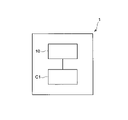
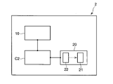
- FIG. 1 is a schematic diagram showing the configuration of a sol production apparatus according to one embodiment.
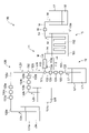
- FIG. 2 is a schematic diagram showing the configuration of the sol production section according to the first embodiment.
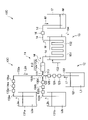
- FIG. 3 is a schematic diagram showing the configuration of the sol production section according to the second embodiment.
- FIG. 4 is a schematic diagram showing the configuration of the sol production section according to the third embodiment.
- FIG. 5 is a schematic diagram showing the configuration of the sol production section according to the fourth embodiment.
- FIG. 6 is a schematic diagram showing the configuration of a sol production section according to the fifth embodiment.
- FIG. 7 is a schematic diagram showing a first modification of the sol production section according to the first to fifth embodiments.
- FIG. 8 is a schematic diagram showing a second modification of the sol production section according to the first to fifth embodiments.
- FIG. 1 is a schematic diagram showing the configuration of a sol production apparatus according to one embodiment.
- FIG. 2 is a schematic diagram showing the configuration of the sol production section according to the first embodiment.
- FIG. 3
- FIG. 9 is a schematic diagram showing a third modification of the sol production section according to the first to fifth embodiments.
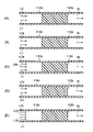
- FIG. 10 is a schematic cross-sectional view for explaining the process of preparing a mixture containing a silica precursor, a catalyst and a macropore-forming agent in a mixer.
- FIG. 11 is a schematic diagram showing the configuration of a gel manufacturing apparatus according to one embodiment.
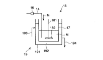
- FIG. 12 is a schematic diagram showing the configuration of a heating section and a sol supply section provided in the gel production section according to one embodiment.
- FIG. 13 is a schematic diagram showing the configuration of a silica porous body manufacturing apparatus according to one embodiment.
- FIG. 14 is a schematic diagram showing the configuration of a porous silica production section according to one embodiment.
- FIG. 15 is an SEM image of the structure of the surface of the silica monolith produced in Example 1, which was confirmed with a scanning electron microscope (SEM).
- FIG. 16 shows SEM images of the surface structures of the silica monoliths produced in Examples 2 to 5, which were confirmed with a scanning electron microscope (SEM).
- FIG. 1 is a schematic diagram showing the configuration of a sol production apparatus 1. As shown in FIG.
- the sol-producing apparatus 1 includes a sol-producing section 10 and a control section C1 that controls the operation of the sol-producing section 10 .
- the sol production unit 10 performs various processes for producing sol. Various processes performed by the sol production unit 10 will be described later.
- the control unit C1 is, for example, a computer, and includes a main control unit and a storage unit.
- the main control unit is, for example, a CPU (Central Processing Unit), and controls the operation of the sol production unit 10 by reading and executing programs, data, etc. stored in the storage unit.
- the storage unit is composed of storage devices such as RAM (Random Access Memory), ROM (Read Only Memory), hard disk, etc., and stores programs, data, etc. for controlling the processing executed in the sol production unit 10. do.
- the program may be recorded on a computer-readable storage medium, or may be installed from the storage medium to the storage unit.
- the recording medium records, for example, a program that, when executed by a computer for controlling the operation of the sol-producing apparatus 1, causes the computer to control the sol-producing apparatus 1 to execute a sol-producing method described later.
- FIG. 2 is a schematic diagram showing the configuration of the sol production section 10A. Arrows in FIG. 2 indicate the direction in which the liquid flows.
- the sol production unit 10A includes a mixing unit 11 that prepares a mixed liquid M containing a silica precursor, a catalyst, and a macropore-forming agent, a first supply unit 12 that supplies the silica precursor to the mixing unit 11, a catalyst and a macropore-forming agent.
- a second supply unit 13A that supplies the forming agent in a mixed state to the mixing unit 11, a discharge pipe 14 that discharges the mixed liquid M from the mixing unit 11, and a cooling that cools the mixed liquid M flowing through the discharge pipe 14 to 35°C or less.
- the sol production section 10A may include a recovery container 17 for recovering the liquid mixture M discharged from the discharge pipe 14 .
- the first supply unit 12 includes a storage tank 121 that stores the raw material liquid L1 containing the silica precursor, a supply pipe 122 that supplies the raw material liquid L1 in the storage tank 121 to the mixing unit 11, and the supply pipe 122. and a pump 123 .
- the first supply unit 12 uses the suction force and discharge force of the pump 123 to supply the raw material liquid L1 in the storage tank 121 to the mixing unit 11 through the supply pipe 122 .
- the silica precursor is supplied to the mixing section 11 by the first supply section 12 in the form of the raw material liquid L1.
- a silica precursor is a silicon compound with a hydrolyzable functional group.
- the number of hydrolyzable functional groups possessed by the silicon compound may be 1 or 2, but from the viewpoint of producing a gel having a highly crosslinked structure by siloxane bonds (-Si-O-Si-), 3 or more. One is preferred, and four is more preferred.
- the silicon compound has two or more hydrolyzable functional groups, the types of the two or more hydrolyzable functional groups may be the same or different.
- a hydrolyzable functional group is a functional group that is converted to a hydroxy group by hydrolysis.
- hydrolyzable functional groups include alkoxy groups, acetoxy groups, halide groups, hydrosilyl groups and the like, with alkoxy groups being preferred.
- the alkoxy group is preferably an alkoxy group having 1 to 10 carbon atoms, more preferably an alkoxy group having 1 to 5 carbon atoms, and even more preferably a methoxy group, an ethoxy group and a propyl group.
- Alkoxy groups may be linear or branched.
- a silicon compound having a hydrolyzable functional group may have a functional group other than the hydrolyzable functional group.
- functional groups other than hydrolyzable functional groups include alkyl groups, alkenyl groups, phenyl groups, phenoxy groups, hydroxyl groups, carboxyl groups, epoxy groups, aldehyde groups, thiol groups, amino groups, acryloyl groups, methacryloyl groups, and the like. be done.
- the alkyl group is preferably an alkyl group having 1 to 10 carbon atoms, more preferably an alkyl group having 1 to 5 carbon atoms, and even more preferably a methyl group, an ethyl group and a propyl group.
- Alkyl groups may be linear or branched.
- the alkenyl group is preferably an alkenyl group having 2 to 10 carbon atoms, more preferably an alkenyl group having 2 to 5 carbon atoms, and even more preferably a vinyl group.
- An alkenyl group may be linear or branched.
- the silicon compound having a hydrolyzable functional group is preferably alkoxysilane.
- alkoxysilanes include tetraalkoxysilanes, trialkoxysilanes, dialkoxysilanes, monoalkoxysilanes, and the like. , trialkoxysilanes and dialkoxysilanes are preferred, tetraalkoxysilanes and trialkoxysilanes are more preferred, and tetraalkoxysilanes are even more preferred.
- tetraalkoxysilane examples include tetramethoxysilane, tetraethoxysilane, tetrapropoxysilane, and the like.
- trialkoxysilane examples include trimethoxysilane, methyltrimethoxysilane, ethyltrimethoxysilane, triethoxysilane, methyltriethoxysilane, ethyltriethoxysilane, tripropoxysilane, methyltripropoxysilane, ethyltripropoxysilane, and the like. is mentioned.
- dialkoxysilanes include methyldimethoxysilane, dimethyldimethoxysilane, methyldiethoxysilane, dimethyldiethoxysilane, ethyldimethoxysilane, diethyldimethoxysilane, ethyldiethoxysilane, diethyldiethoxysilane, and the like.
- Examples of monoalkoxysilanes include dimethylmethoxysilane and dimethylethoxysilane.
- the raw material liquid L1 may contain a solvent.
- the solvent is water.
- the solvent is a mixed solvent of water and organic solvent.
- organic solvents include alcohols such as methanol, ethanol, n-propanol, 2-propanol, ethylene glycol, propylene glycol and 1,4-butanediol; ketones such as acetone and methyl ethyl ketone.
- the content of the organic solvent is preferably 65% by mass or less based on the mass of the mixed solvent.
- the raw material liquid L1 may be composed of the silica precursor alone without containing a solvent.
- the supply pipe 122 may be provided with a flow meter 124 that detects the flow rate of the raw material liquid L1 flowing through the supply pipe 122 .
- the supply pipe 122 may be provided with a flow rate regulator 125 that adjusts the flow rate of the raw material liquid L1 flowing through the supply pipe 122 .
- Flow regulator 125 is, for example, a valve.
- the flow rate regulator 125 may adjust the flow rate of the raw material liquid L1 flowing through the supply pipe 122 based on the flow rate of the raw material liquid L1 detected by the flow meter 124 .
- FIG. 2 shows, as an embodiment, a configuration in which the pump 123, the flowmeter 124, and the flow rate regulator 125 are arranged in order in the flow direction of the raw material liquid L1.
- the design may be such that the flow rate regulator 125 is omitted by using a device having both of the above, or the design may be such that the arrangement order of the flow rate meter 124 and the flow rate regulator 125 is reversed. Similar design changes are possible in each embodiment, each modified example, and the like, which will be described below.
- the second supply unit 13A includes a storage tank 131 that stores the raw material liquid L2 containing the catalyst and the macropore forming agent, a supply pipe 132 that supplies the raw material liquid L2 in the storage tank 131 to the mixing unit 11, and and a pump 133 provided.
- the second supply unit 13A uses the suction force and discharge force of the pump 133 to supply the raw material liquid L2 in the storage tank 131 to the mixing unit 11 through the supply pipe 132 .
- the catalyst and the macropore-forming agent are supplied to the mixing section 11 in the form of the raw material liquid L2 (that is, in a mixed state) by the second supply section 13A.
- the catalyst functions as a catalyst for the hydrolysis reaction.
- catalysts include acids, bases, and the like.
- acids include inorganic acids such as hydrochloric acid, sulfuric acid and nitric acid; and organic acids such as formic acid, acetic acid, oxalic acid and citric acid.
- the base include sodium hydroxide, potassium hydroxide, aqueous ammonia, sodium carbonate, sodium hydrogen carbonate, amines such as trimethylammonium, ammonium hydroxides such as tert-butylammonium hydroxide, and alkalis such as sodium methoxide. metal alkoxides and the like.
- water-soluble polymers include polyalkylene glycols such as polyethylene glycol and polypropylene glycol, polyacrylic acid, polyethylene glycol-polypropylene glycol block copolymers, polyvinylpyrrolidone, sodium polystyrenesulfonate, and polyallylamine hydrochloride. .
- the weight average molecular weight of the water-soluble polymer is preferably 8000 or more and 15000 or less. Weight average molecular weight is measured by GPC (gel permeation chromatography).
- surfactants include cationic surfactants such as cetyltrimethylammonium chloride, anionic surfactants such as sodium dodecyl sulfate, and nonionic surfactants such as polyoxyethylene alkyl ethers. .
- the raw material liquid L2 may contain a solvent.
- the above explanation regarding the solvent contained in the raw material liquid L1 also applies to the solvent contained in the raw material liquid L2.
- the raw material liquid L2 may contain a mesopore-forming agent.
- the mesopore-forming agent contributes to the formation of mesopores in the silica porous material.
- mesopore-forming agents include nitrogen compounds.
- nitrogen compounds that can be used as mesopore-forming agents include amide compounds such as urea, formamide, N-methylformamide, N,N-dimethylformamide, acetamide, N-methylacetamide, and N,N-dimethylacetamide;
- Examples include heterocyclic compounds such as methylenetetramine, and among these, urea is preferred from the viewpoint of efficient formation of mesopores.
- the supply pipe 132 may be provided with a flow meter 134 that detects the flow rate of the raw material liquid L2 flowing through the supply pipe 132 .
- the supply pipe 132 may be provided with a flow rate regulator 135 that adjusts the flow rate of the raw material liquid L2 flowing through the supply pipe 132 .
- Flow regulator 135 is, for example, a valve.
- the flow rate regulator 135 may adjust the flow rate of the raw material liquid L2 flowing through the supply pipe 132 based on the flow rate of the raw material liquid L2 detected by the flowmeter 134 .
- the mixing section 11 includes a confluence section 111 , a mixer 112 , and a connection pipe 113 that connects the confluence section 111 and the mixer 112 .
- the mixer 112 includes a mixing tube 112a and a mixing section 112b provided inside the mixing tube 112a.
- the mixer 112 is generally called a line mixer or an in-line mixer, and mixes the liquid flowing through the mixing tube 112a by the mixing section 112b.
- connection pipe 113 One end of the connection pipe 113 is connected to the confluence portion 111, and the other end of the connection pipe 113 is connected to an inlet formed at the upstream end of the mixing pipe 112a.
- the raw material liquids L1 and L2 merged at the confluence portion 111 flow into the mixing pipe 112a through the connection pipe 113 and the inlet of the mixing pipe 112a.
- the connecting pipe 113 may be integrated with the pipe constituting the confluence portion 111 and/or the mixing pipe 112a of the mixer 111 (that is, the connecting pipe 113 and the pipe and/or the mixer constituting the confluence portion 111).
- the mixing tube 112a of 111 may consist of one tube).
- the mixing unit 112b flows into the mixing tube 112a and mixes the raw material liquids L1 and L2 flowing downstream in the mixing tube 112a to prepare a mixed liquid M containing a silica precursor, a catalyst, and a macropore forming agent. do.
- the mixed liquid M further contains a mesopore-forming agent.
- Examples of the mixer 112 include static mixers and dynamic mixers.
- the static mixer mixes the raw material liquids L1 and L2 to prepare the mixed liquid M without using power.
- the mixing section 112b in the static mixer includes, for example, a twisted blade-shaped mixing element (a shape in which a rectangular plate is twisted at a predetermined twisting angle around its longitudinal central axis).
- the mixing unit 112b in the static mixer mixes the raw material liquids L1 and L2 without using power by dividing, rejoining, or reversing the flow of the raw material liquids L1 and L2, and the mixed liquid M to prepare.
- the dynamic mixer uses power to mix raw material liquids L1 and L2 to prepare mixed liquid M.
- Dynamic mixers include, for example, homogenizers and homomixers.
- the mixing unit 112b in the dynamic mixer includes, for example, a shaft, a stirring blade provided on the shaft, and a driving unit for rotating the shaft. are mixed to prepare a mixed liquid M.
- the liquid mixture M prepared by the mixing section 112b flows downstream in the mixing tube 112a and flows out of the mixing tube 112a through an outlet formed at the downstream end of the mixing tube 112a.
- One end of the discharge pipe 14 is connected to the outlet of the mixing pipe 112a, and the mixed liquid M flowing out of the outlet of the mixing pipe 112a flows through the discharge pipe 14 and is discharged from the other end of the discharge pipe 14. .
- the mixed liquid M discharged from the other end of the discharge pipe 14 is recovered in a recovery container 17, for example.
- the cooling unit 15 includes a cooling bath 151 and a cooling medium 152 contained in the cooling bath 151 .
- At least part of the discharge pipe 14 is in contact with the cooling medium 152 of the cooling section 15 , and the mixed liquid M flowing through the discharge pipe 14 is cooled by the cooling medium 152 .
- the cooling medium 152 is a liquid such as cooling water
- a portion of the discharge pipe 14 immersed in the cooling medium 152 contacts the cooling medium 152 .
- the shape of the portion of the discharge pipe 14 that is in contact with the cooling medium 152 may be linear, meandering, or spiral.
- the time during which the liquid mixture M flowing through the discharge pipe 14 is cooled by the cooling medium 152 includes the inner diameter and length of the portion of the discharge pipe 14 that is in contact with the cooling medium 152, the flow rate of the liquid mixture M flowing through the discharge pipe 14, and the like. can be adjusted by adjusting
- the inner diameter of the portion of the discharge pipe 14 that is in contact with the cooling medium 152 is preferably 0.5 mm or more and 200 mm or less, and is 0.5 mm or more and 100 mm or less. is more preferable.
- the length of the portion of the discharge pipe 14 that is in contact with the cooling medium 152 is preferably 50 mm or more and 10000 mm or less, more preferably 50 mm or more and 8000 mm or less. preferable.
- the flow rate of the mixed liquid M flowing through the discharge pipe 14 is preferably 5 mL/min or more and 3000 mL/min or less, and is preferably 10 mL/min or more and 500 mL/min or less. more preferred.
- the cooling unit 15 may include a cooling medium supply unit 153 that supplies the cooling medium 152 to the cooling tank 151 and a cooling medium discharge unit 154 that discharges the cooling medium 152 from the cooling tank 151 .
- the cooling medium 152 is, for example, liquid such as cooling water.
- the cooling medium 152 may be gas.
- the cooling unit 15 cools the liquid mixture M flowing through the discharge pipe 14 to 35° C. or less with the cooling medium 152 .
- the cooling unit 15 cools the liquid mixture M flowing through the discharge pipe 14 to 35° C. or less with the cooling medium 152 .
- the temperature of the mixed liquid M that is "35°C or less" is the temperature of the mixed liquid M immediately after being cooled by the cooling unit 15.
- the temperature of the mixed liquid M immediately after being cooled by the cooling unit 15 is detected, for example, after the mixed liquid M is cooled by the cooling medium 152 and before the mixed liquid M is collected in the collection container 17. be.
- thermometer 16 that detects the temperature of the liquid mixture M flowing through the discharge pipe 14 may be provided downstream of the portion of the discharge pipe 14 that is in contact with the cooling medium 152 .
- thermometer 16 The temperature of the liquid mixture M immediately after being cooled by the cooling unit 15 is detected by the thermometer 16, for example.
- the temperature of the mixed liquid M immediately after being cooled by the cooling unit 15 is preferably 35° C. or lower, more preferably 30° C. or lower, from the viewpoint of obtaining a homogeneous sol that enables appropriate formation of macropores. more preferred.
- the lower limit may be any temperature at which the liquid mixture M does not freeze, and specifically, it is preferably about 1°C or 2°C.
- the cooling unit 15 may adjust the temperature of the cooling medium 152 based on the temperature of the liquid mixture M detected by the thermometer 16. For example, the cooling unit 15 determines the temperature and/or flow rate of the cooling medium 152 supplied by the cooling medium supply unit 153, and the temperature and/or flow rate of the cooling medium 152 supplied by the cooling medium supply unit 153, and The flow rate or the like of the cooling medium 152 may be adjusted.
- FIG. 3 is a schematic diagram showing the configuration of the sol production section 10B.
- the arrows in FIG. 3 indicate the direction in which the liquid flows.
- the sol production unit 10B includes a mixing unit 11 that prepares a mixed liquid M containing a silica precursor, a catalyst, and a macropore-forming agent, a first supply unit 12 that supplies the silica precursor to the mixing unit 11, a catalyst and a macropore-forming agent.
- a second supply part 13B that supplies the forming agent in a mixed state to the mixing part 11, a discharge pipe 14 that discharges the mixed liquid M from the mixing part 11, and a cooling that cools the mixed liquid M flowing through the discharge pipe 14 to 35 ° C. or less a part 15;
- the sol production section 10B may include a recovery container 17 for recovering the mixed liquid M discharged through the discharge pipe 14 .
- sol production section 10A applies to the configurations of the sol production section 10B that are denoted by the same reference numerals as those of the sol production section 10A.
- the configuration of the sol-producing section 10B that is different from that of the sol-producing section 10A will be described below.
- the sol production section 10B differs from the sol production section 10A in that a second supply section 13B is employed.
- the second supply unit 13B includes a storage tank 131a that stores the raw material liquid L2a containing the catalyst, a supply pipe 132a that supplies the raw material liquid L2a in the storage tank 131a to the confluence unit 130, and a pump 133a provided in the supply pipe 132a. and
- the second supply unit 13B includes a storage tank 131b that stores the raw material liquid L2b containing the macropore forming agent, a supply pipe 132b that supplies the raw material liquid L2b in the storage tank 131b to the confluence unit 130, and the supply pipe 132b. and a pump 133b provided.
- the second supply section 13B also includes a supply pipe 132d that supplies the mixed liquid L2d, which is the mixed liquid of the raw material liquids L2a and L2b generated in the confluence section 130, to the mixing section 11. As shown in FIG.
- the confluence portion 130 is a portion where the supply pipe 132a and the supply pipe 132b are merged.
- the raw material liquid L2a supplied through the supply pipe 132a and the raw material liquid L2b supplied through the supply pipe 132b join together at the confluence portion .
- the above description regarding the catalyst also applies to the catalyst contained in the raw material liquid L2a, and the above description regarding the macropore forming agent also applies to the macropore forming agent contained in the raw material liquid L2b.
- the raw material liquids L2a and L2b may contain a solvent.
- the above explanation regarding the solvent contained in the raw material liquid L1 also applies to the solvents contained in the raw material liquids L2a and L2b.
- the raw material liquid L2a When the catalyst is liquid at room temperature, the raw material liquid L2a may be composed of the catalyst alone without containing the solvent.
- the raw material liquid L2b When the macropore-forming agent is liquid at room temperature, the raw material liquid L2b may be composed solely of the macropore-forming agent without containing a solvent.
- the raw material liquid L2a and/or L2b may contain a mesopore-forming agent.
- the above explanation regarding the mesopore-forming agent also applies to the mesopore-forming agent contained in the raw material liquids L2a and/or L2b.
- the mesopore-forming agent is supplied by the second supply unit 13B in the form of a mixed liquid L2d (that is, in a mixed state with the catalyst and the macropore-forming agent). It is supplied to the mixing section 11 .
- the supply pipe 132a may be provided with a flow rate regulator 135a for adjusting the flow rate of the raw material liquid L2a flowing through the supply pipe 132a.
- the flow regulator 135a is, for example, a valve.
- the flow rate regulator 135a may adjust the flow rate of the raw material liquid L2a flowing through the supply pipe 132a based on the flow rate of the raw material liquid L2a detected by the flowmeter 134a.
- the supply pipe 132b may be provided with a flow meter 134b for detecting the flow rate of the raw material liquid L2b flowing through the supply pipe 132b.
- the supply pipe 132b may be provided with a flow rate regulator 135b that adjusts the flow rate of the raw material liquid L2b flowing through the supply pipe 132b.
- the flow regulator 135b is, for example, a valve.
- the flow rate regulator 135b may adjust the flow rate of the raw material liquid L2b flowing through the supply pipe 132b based on the flow rate of the raw material liquid L2b detected by the flow meter 134b.
- the mixing section 112b of the mixer 112 mixes the raw material liquid L1 and the mixed liquid L2d flowing into the mixing tube 112a and flowing downstream in the mixing tube 112a to mix the silica precursor, the catalyst and the macropore forming agent.
- the raw material liquids L2a and/or L2b contain a mesopore-forming agent
- the mixed liquid M further contains a mesopore-forming agent.
- FIG. 4 is a schematic diagram showing the configuration of the sol production section 10C.
- the arrows in FIG. 4 indicate the directions in which the liquid flows.
- the sol production unit 10C includes a mixing unit 11 that prepares a mixed liquid M containing a silica precursor, a catalyst, and a macropore-forming agent, a first supply unit 12 that supplies the silica precursor to the mixing unit 11, a catalyst and a macropore-forming agent.
- a second supply unit 13C that separately supplies the forming agent to the mixing unit 11, a discharge pipe 14 that discharges the mixed liquid M from the mixing unit 11, and a cooling unit that cools the mixed liquid M flowing through the discharge pipe 14 to 35°C or less.
- the sol production section 10C may include a recovery container 17 for recovering the mixed liquid M discharged through the discharge pipe 14 .
- sol production section 10B applies to the configurations of the sol production section 10C that are denoted by the same reference numerals as those of the sol production section 10B, unless otherwise specified.
- the configuration of the sol-producing section 10C that is different from that of the sol-producing section 10B will be described below.
- the sol-producing section 10C differs from the sol-producing section 10B in that a second supply section 13C that separately supplies the catalyst and the macropore-forming agent to the mixing section 11 is employed.
- the second supply unit 13C includes a storage tank 131a that stores the raw material liquid L2a containing the catalyst, a supply pipe 132a that supplies the raw material liquid L2a in the storage tank 131a to the mixing unit 11, and a pump 133a provided in the supply pipe 132a. and
- the second supply unit 13C includes a storage tank 131b that stores the raw material liquid L2b containing the macropore forming agent, a supply pipe 132b that supplies the raw material liquid L2b in the storage tank 131b to the mixing unit 11, and the supply pipe 132b. and a pump 133b provided.
- the second supply unit 13C uses the suction force and discharge force of the pump 133a to supply the raw material liquid L2a in the storage tank 131a to the mixing unit 11 through the supply pipe 132a.
- the second supply unit 13C also supplies the raw material liquid L2b in the storage tank 131b to the mixing unit 11 through the supply pipe 132b using the suction force and the discharge force of the pump 133b.
- the catalyst and the macropore-forming agent are supplied to the mixing section 11 in the form of the raw material liquids L2a and L2b, respectively (that is, separately) by the second supply section 13C.
- the mesopore-forming agent is supplied to the mixing section 11 in the form of the raw material liquid L2a (that is, in a mixed state with the catalyst) by the second supply section 13C.
- the mesopore-forming agent is supplied to the mixing section 11 in the form of the raw material liquid L2b (that is, in a mixed state with the macropore-forming agent) by the second supply section 13C. be.
- the confluence portion 111 of the mixing portion 11 is a portion where the supply pipe 122, the supply pipe 132a, and the supply pipe 132b are merged.
- the raw material liquid L1 supplied through the supply pipe 122, the raw material liquid L2a supplied through the supply pipe 132a, and the raw material liquid L2b supplied through the supply pipe 132b are joined at the confluence portion 111.
- the raw material liquids L1, L2a, and L2b merged at the confluence portion 111 flow into the mixing tube 112a through the connection pipe 113 and the inlet of the mixing pipe 112a.
- the mixing section 112b of the mixer 112 mixes the raw material liquids L1, L2a, and L2b that flow into the mixing tube 112a and flow downstream in the mixing tube 112a to mix the silica precursor, the catalyst, and the macropore-forming agent.
- the raw material liquids L2a and/or L2b contain a mesopore-forming agent
- the mixed liquid M further contains a mesopore-forming agent.
- the sol production unit 10D includes a mixing unit 11 that prepares a mixed liquid M containing a silica precursor, a catalyst, a macropore forming agent, and a mesopore forming agent, and a first supply unit 12 that supplies the silica precursor to the mixing unit 11. , a second supply unit 13D that supplies the catalyst, the macropore-forming agent, and the mesopore-forming agent in a mixed state to the mixing unit 11; a discharge pipe 14 that discharges the mixed liquid M from the mixing unit 11; and a cooling unit 15 for cooling the liquid M to 35° C. or lower.
- the sol production section 10D may include a recovery container 17 for recovering the mixed liquid M discharged through the discharge pipe 14 .
- sol production section 10B applies to the configurations of the sol production section 10D that are denoted by the same reference numerals as those of the sol production section 10B, unless otherwise specified.
- the configuration of the sol-producing section 10D that differs from that of the sol-producing section 10B will be described below.
- the sol-producing section 10D differs from the sol-producing section 10B in that a second supply section 13D that supplies the catalyst, the macropore-forming agent, and the mesopore-forming agent in a mixed state to the mixing section 11 is employed.
- the second supply unit 13D includes a storage tank 131a that stores the raw material liquid L2a containing the catalyst, a supply pipe 132a that supplies the raw material liquid L2a in the storage tank 131a to the confluence unit 130, and a pump 133a provided in the supply pipe 132a. and
- the second supply unit 13D includes a storage tank 131b that stores the raw material liquid L2b containing the macropore forming agent, a supply pipe 132b that supplies the raw material liquid L2b in the storage tank 131b to the confluence unit 130, and the supply pipe 132b. and a pump 133b provided.
- the second supply unit 13D includes a storage tank 131c that stores the raw material liquid L2c containing the mesopore forming agent, a supply pipe 132c that supplies the raw material liquid L2c in the storage tank 131c to the confluence unit 130, and the supply pipe 132c. and a pump 133c provided.
- the second supply section 13D also includes a supply pipe 132e that supplies a mixed liquid L2e, which is a mixed liquid of the raw material liquids L2a, L2b, and L2c generated in the confluence section 130, to the mixing section 11.
- the second supply unit 13D uses the suction force and discharge force of the pump 133a to supply the raw material liquid L2a in the storage tank 131a to the confluence unit 130 through the supply pipe 132a. Also, the second supply unit 13D supplies the raw material liquid L2b in the storage tank 131b to the confluence unit 130 through the supply pipe 132b using the suction force and the discharge force of the pump 133b. Also, the second supply unit 13D supplies the raw material liquid L2c in the storage tank 131c to the confluence unit 130 through the supply pipe 132c using the suction force and the discharge force of the pump 133c.
- the second supply section 13D uses the discharge forces of the pumps 133a, 133b, and 133c to supply the mixed liquid L2e generated in the confluence section 130 to the mixing section 11 through the supply pipe 132e.
- the catalyst, the macropore-forming agent, and the mesopore-forming agent are supplied to the mixing section 11 in the form of the liquid mixture L2e (that is, in a mixed state) by the second supply section 13D.
- mesopore-forming agent also applies to the mesopore-forming agent contained in the raw material liquid L2c.
- the raw material liquid L2c may contain a solvent.
- the above description regarding the solvent contained in the raw material liquid L1 also applies to the solvent contained in the raw material liquid L2c.
- the supply pipe 132c may be provided with a flow meter 134c for detecting the flow rate of the raw material liquid L2c flowing through the supply pipe 132c.
- the supply pipe 132a, the supply pipe 132b, and the supply pipe 132c are joined at the junction 130.
- the raw material liquid L2a supplied through the supply pipe 132a, the raw material liquid L2b supplied through the supply pipe 132b, and the raw material liquid L2c supplied through the supply pipe 132c are merged at the confluence section 130 to form the raw material liquids L2a, L2b, and A mixture L2e is produced which is a mixture of L2c.
- the liquid mixture L2e generated in the confluence section 130 is supplied to the mixing section 11 through the supply pipe 132e.
- the confluence section 111 of the mixing section 11 is a section where the supply pipe 122 and the supply pipe 132e are merged.
- the raw material liquid L1 supplied through the supply pipe 122 and the liquid mixture L2e supplied through the supply pipe 132e join together at the confluence portion 111 .
- the raw material liquid L1 and the liquid mixture L2e that have merged at the confluence portion 111 flow into the mixing tube 112a through the connecting tube 113 and the inlet of the mixing tube 112a.
- the mixing section 112b of the mixer 112 flows into the mixing tube 112a, mixes the raw material liquid L1 and the mixed liquid L2e flowing downstream in the mixing tube 112a, and mixes the silica precursor, catalyst, macropore forming agent and A mixture M containing a mesopore-forming agent is prepared.
- the supply pipe 132c may be joined with the supply pipe 132a at a portion other than the junction portion 130.
- the supply pipe 132c may be merged with the supply pipe 132a at a portion of the supply pipe 132a upstream of the confluence portion 130 (for example, a portion located between the flow regulator 135a and the confluence portion 130). good.
- the supply pipe 132c may be joined with the supply pipe 132b at a portion other than the junction portion 130.
- the supply pipe 132c may be merged with the supply pipe 132b at a portion of the supply pipe 132b upstream of the confluence portion 130 (for example, a portion located between the flow rate regulator 135b and the confluence portion 130). good.
- the storage tank 131a, the supply pipe 132a, and the pump 133a may be omitted, and the catalyst may be included in the raw material liquid L2b.
- the storage tank 131b, the supply pipe 132b and the pump 133b may be omitted, and the raw material liquid L2a may contain the macropore forming agent.
- FIG. 6 is a schematic diagram showing the configuration of the sol production section 10E.
- the arrows in FIG. 6 indicate the direction in which the liquid flows.
- the sol production unit 10E includes a mixing unit 11 that prepares a mixed liquid M containing a silica precursor, a catalyst, a macropore forming agent, and a mesopore forming agent, and a first supply unit 12 that supplies the silica precursor to the mixing unit 11. , a second supply unit 13E that separately supplies the catalyst, the macropore-forming agent, and the mesopore-forming agent to the mixing unit 11; a discharge pipe 14 that discharges the mixed liquid M from the mixing unit 11; and a cooling unit 15 for cooling M to 35° C. or lower.
- the sol production section 10E may include a recovery container 17 for recovering the mixed liquid M discharged through the discharge pipe 14 .
- the above description of the sol-producing section 10D applies, unless otherwise specified.
- the configuration of the sol-producing section 10E that differs from that of the sol-producing section 10D will be described below.
- the sol-producing section 10E differs from the sol-producing section 10D in that a second supply section 13E that separately supplies the catalyst, the macropore-forming agent, and the mesopore-forming agent to the mixing section 11 is employed.
- the second supply unit 13E includes a storage tank 131a that stores the raw material liquid L2a containing the catalyst, a supply pipe 132a that supplies the raw material liquid L2a in the storage tank 131a to the mixing unit 11, and a pump 133a provided in the supply pipe 132a. and
- the second supply unit 13E includes a storage tank 131b that stores the raw material liquid L2b containing the macropore forming agent, a supply pipe 132b that supplies the raw material liquid L2b in the storage tank 131b to the mixing unit 11, and the supply pipe 132b. and a pump 133b provided.
- the second supply unit 13E includes a storage tank 131c that stores the raw material liquid L2c containing the mesopore-forming agent, a supply pipe 132c that supplies the raw material liquid L2c in the storage tank 131c to the mixing unit 11, and the supply pipe 132c. and a pump 133c provided.
- the second supply unit 13E uses the suction force and discharge force of the pump 133a to supply the raw material liquid L2a in the storage tank 131a to the mixing unit 11 through the supply pipe 132a. Further, the second supply unit 13E uses the suction force and the discharge force of the pump 133b to supply the raw material liquid L2b in the storage tank 131b to the mixing unit 11 through the supply pipe 132b. Further, the second supply unit 13E uses the suction force and the discharge force of the pump 133c to supply the raw material liquid L2c in the storage tank 131c to the mixing unit 11 through the supply pipe 132c.
- the confluence portion 111 of the mixing section 11 is a portion where the supply pipe 122, the supply pipe 132a, the supply pipe 132b, and the supply pipe 132c are merged.
- the raw material liquid L1 supplied through the supply pipe 122, the raw material liquid L2a supplied through the supply pipe 132a, the raw material liquid L2b supplied through the supply pipe 132b, and the raw material liquid L2c supplied through the supply pipe 132c are merged.
- the raw material liquids L1, L2a, L2b, and L2c merged at the confluence portion 111 flow into the mixing pipe 112a through the connection pipe 113 and the inlets of the mixing pipe 112a.
- the mixing section 112b of the mixer 112 flows into the mixing tube 112a and mixes the raw material liquids L1, L2a, L2b, and L2c flowing downstream in the mixing tube 112a, thereby mixing the silica precursor, catalyst, and macropore formation.
- a mixed solution M is prepared containing a mesopore-forming agent and a mesopore-forming agent.
- the storage tank 131a, the supply pipe 132a and the pump 133a may be omitted, and the catalyst may be included in the raw material liquid L2b.
- FIG. 7 is a schematic diagram showing a first modification of the sol production units 10A to 10E.
- the arrows in FIG. 7 indicate the direction in which the liquid flows.
- a first modified example of the sol production units 10A to 10E includes a stirring unit 18 for stirring the mixture M contained in the collection container 17.
- the stirring section 18 When the flow rate of the mixed liquid M is large, it is preferable to provide a stirring section 18 in order to prepare a homogeneous sol that enables appropriate formation of macropores. Specifically, when the flow rate of the liquid mixture M is 15 mL/min or more, it is preferable to provide the stirring unit 18 .
- the cooling unit 19 includes, for example, a cooling jacket 191 provided on the outer surface of the collection container 17 and a cooling medium 192 accommodated in the cooling jacket 191 . Cool the liquid M.
- the cooling unit 19 may include a cooling medium supply unit 193 that supplies the cooling medium 192 to the cooling jacket 191 and a cooling medium discharge unit 194 that discharges the cooling medium 192 from the cooling jacket 191 .
- the cooling medium 192 is, for example, liquid such as cooling water. Cooling medium 192 may be a gas.
- FIG. 8 is a schematic diagram showing a second modification of the sol production units 10A to 10E.
- the arrows in FIG. 8 indicate the directions in which the liquid flows.
- the mixed liquid M discharged from the discharge pipe 14 or the mixed liquid M contained in the recovery container 17 is transferred to the first container V1, the second container V2, ..., the n-th container Vn.
- a supply unit for supplying is provided.
- a second modification of the sol production units 10A to 10E includes a supply pipe P0 for supplying the mixed solution M contained in the recovery container 17 to the channel switching unit 171a, and the mixed solution M supplied to the channel switching unit 171a. to the first container V1, the second container V2, . . . , the n-th container Vn, respectively.
- the supply pipe P0 may be provided with a flow meter 173a for detecting the flow rate of the liquid mixture M flowing through the supply pipe P0.
- the supply pipe P0 may be provided with a flow rate regulator 174a that adjusts the flow rate of the liquid mixture M flowing through the supply pipe P0.
- the flow regulator 174a is, for example, a valve.
- the flow rate regulator 174a may adjust the flow rate of the mixed liquid M flowing through the supply pipe P0 based on the flow rate of the mixed liquid M detected by the flow meter 173a.
- the channel switching unit 171a is, for example, a channel switching valve.
- the channel switching unit 171a switches channels as follows. First, the channel switching unit 171a selects the supply pipe P1 connected to the first container V1 as the channel for the liquid mixture M. As shown in FIG. Thereby, the liquid mixture M is supplied to the first container V1. After a predetermined amount of the mixed liquid M is supplied to the first container V1, the flow path switching unit 171a switches the flow path of the mixed liquid M, and sets the flow path of the mixed liquid M to the supply pipe connected to the second container V2. Select P2. Thereby, the liquid mixture M is supplied to the second container V2.
- the flow path switching unit 171a switches the flow path of the mixed liquid M, and sets the flow path of the mixed liquid M to a supply pipe connected to the third container V3. Select P3. Thereby, the liquid mixture M is supplied to the third container V3.
- a predetermined amount of the liquid mixture M is supplied to the first container V1, the second container V2, . . . , the n-th container Vn.
- the second modification may be combined with the first modification.
- the recovery container 17 may be omitted and one end of the discharge pipe 14 and one end of the supply pipe P0 may be connected.
- the discharge pipe 14 and the supply pipe P0 may be integrated (that is, the discharge pipe 14 and the supply pipe P0 may be composed of one pipe).
- the first container V1 the second container V2, .
- FIG. 9 is a schematic diagram showing a third modification of the sol production units 10A to 10E.
- the arrows in FIG. 9 indicate the direction in which the liquid flows.
- the mixed liquid M discharged from the discharge pipe 14 or the mixed liquid M contained in the recovery container 17 is transferred to the first container V1, the second container V2, ..., the n-th container Vn.
- a supply unit for supplying is provided.
- a third modification of the sol production units 10A to 10E includes a nozzle N for supplying the mixture M contained in the recovery container 17 to the first container V1, the second container V2, . ing.
- the nozzle N is connected to a supply pipe P that supplies the mixed liquid M contained in the recovery container 17 to the nozzle N.
- a pump 172b is provided in the supply pipe P, and the mixed liquid M contained in the recovery container 17 is supplied to the nozzle N by the suction force and discharge force of the pump 172b.
- the supply pipe P may be provided with a flow meter 173b that detects the flow rate of the liquid mixture M flowing through the supply pipe P.
- the supply pipe P may be provided with a flow rate regulator 174b that adjusts the flow rate of the liquid mixture M flowing through the supply pipe P.
- Flow regulator 174b is, for example, a valve.
- the flow controller 174b may adjust the flow rate of the liquid mixture M flowing through the supply pipe P based on the flow rate of the liquid mixture M detected by the flowmeter 173b.
- the nozzle N can be moved by a nozzle moving mechanism 440.
- the nozzle moving mechanism 440 has an arm 441 , a moving body 442 with a built-in driving mechanism that can move along the arm 441 , and a turning lifting mechanism 443 that turns and lifts the arm 441 .
- Nozzle N is attached to moving body 442 .
- the nozzle moving mechanism 440 can move the nozzle N above a predetermined container.
- the nozzle N supplies the liquid mixture M to each container as follows.
- the nozzle moving mechanism 440 moves the nozzle N above the first container V1.
- the nozzle N moved above the first container V1 discharges the liquid mixture M toward the first container V1.
- the liquid mixture M is supplied to the first container V1.
- the nozzle moving mechanism 440 moves the nozzle N above the second container V2.
- the nozzle N moved above the second container V2 discharges the liquid mixture M toward the second container V2.
- the liquid mixture M is supplied to the second container V2.
- the nozzle moving mechanism 440 moves the nozzle N above the third container V3.
- the nozzle N moved above the third container V3 discharges the liquid mixture M toward the third container V3. Thereby, the liquid mixture M is supplied to the third container V3.
- a predetermined amount of the liquid mixture M is supplied to the first container V1, the second container V2, . . . , the n-th container Vn.
- the third modification may be combined with the first modification.
- the recovery container 17 may be omitted and one end of the discharge pipe 14 and one end of the supply pipe P may be connected.
- the discharge pipe 14 and the supply pipe P may be integrated (that is, the discharge pipe 14 and the supply pipe P may be composed of one pipe).
- the sol production method includes the following steps: (1A) a step of supplying a silica precursor to the mixing section 11; (1B) supplying the catalyst and the macropore-forming agent in a mixed state or separately to the mixing section 11; (1C) preparing a mixture M containing a silica precursor, a catalyst and a macropore-forming agent in the mixing section 11; and cooling the mixture M flowing through the discharge pipe 14 to 35° C. or less while discharging the .
- Steps 1A to 1D are performed by the sol production department 10.
- the operation of the sol production section 10 is controlled by the control section C1. That is, the control section C1 causes the sol production section 10 to perform steps 1A to 1D.
- Step 1A is a step of supplying the silica precursor to the mixing section 11 .
- the step 1A is performed by the first supply section 12, for example.
- the first supply unit 12 adjusts the amount of silica precursor supplied to the mixing unit 11, the timing of supplying the silica precursor to the mixing unit 11, the time of supplying the silica precursor to the mixing unit 11, and the like. can be done. Therefore, by performing the step 1A by the first supply unit 12, the silica precursor can be supplied under sufficiently controlled conditions, and the mixed liquid M is solated (hydrolysis reaction and polycondensation reaction). can proceed under well-controlled conditions.
- the first supply unit 12 continuously supply the raw material liquid L1 to the mixing unit 11 for a predetermined time.
- the time period during which the first supply unit 12 continuously supplies the raw material liquid L1 is determined by adjusting the capacity (diameter and length) of the supply pipe 122, the pump 123 is properly adjusted in consideration of the suction force and discharge force.
- the time for which the first supply unit 12 continuously supplies the raw material liquid L1 is, for example, 2 seconds or more.
- the upper limit is not particularly limited, and can be appropriately adjusted according to the amount of sol to be produced.
- the flow rate of the raw material liquid L1 supplied by the first supply unit 12 is appropriately adjusted in consideration of the concentration of the raw material liquid L1 and the like so as to obtain a homogeneous sol that enables appropriate formation of macropores.
- the flow rate of the raw material liquid L1 supplied by the first supply unit 12 is preferably 3 mL/min or more and 450 mL/min or less, and is 3 mL/min or more and 200 mL/min or less. is more preferable, and more preferably 3 mL/min or more and 100 mL/min or less.
- Step 1B is a step of supplying the catalyst and the macropore forming agent to the mixing section 11 in a mixed state or separately.
- step 1B the mesopore-forming agent is added in admixture with one or both of the catalyst and the macropore-forming agent, or the catalyst and the macropore-forming agent It is supplied to the mixing section 11 separately from the forming agent.
- the step 1B is preferably carried out in the mixing section 11 so that the catalyst and the macropore-forming agent are in contact with the silica precursor at the same time.
- step 1B is performed in the mixing section 11 such that the catalyst, the macropore-forming agent and the mesopore-forming agent are in contact with the silica precursor simultaneously. is preferred.
- the step 1B is performed, for example, by the second supply section 13A, 13B, 13C, 13D or 13E.
- the second supply section 13A, 13B, 13C, 13D or 13E determines the amount of macropore-forming agent and optionally mesopore-forming agent supplied to the mixing section 11, the amount of macropore-forming agent and optionally mesopore-forming agent in the mixing section. 11, the time during which the macropore-forming agent and optionally the mesopore-forming agent are supplied to the mixing section 11, etc., can be adjusted.
- Step 1B is therefore carried out by means of the second supply 13A, 13B, 13C, 13D or 13E, so that the supply of the catalyst, the macropore former and optionally the mesopore former under well-controlled conditions. , and the solification (hydrolysis reaction and polycondensation reaction) of the mixture M can proceed under well-controlled conditions.
- step 1B When step 1B is performed by the second feeder 13A, the second feeder 13A feeds the catalyst, the macropore-forming agent and optionally the mesopore-forming agent in the form of the raw material liquid L2 (i.e. in mixed state) into the mixing section. 11.
- the second supply unit 13A uses the suction force and the discharge force of the pump 133 to supply the raw material liquid L2 in the storage tank 131 to the mixing unit 11 through the supply pipe 132 .
- the second supply unit 13A continuously supply the raw material liquid L2 to the mixing unit 11 for a predetermined time.
- the time period during which the second supply unit 13A continuously supplies the raw material liquid L2 is determined by the capacity (diameter and length) of the supply pipe 132, the pump 133 is properly adjusted in consideration of the suction force and discharge force.
- the time for which the second supply unit 13A continuously supplies the raw material liquid L2 is, for example, 2 seconds or more.
- the upper limit is not particularly limited, and can be appropriately adjusted according to the amount of sol to be produced.
- the time period during which the second supply unit 13B continuously supplies the mixed liquid L2d, the time period during which the second supply unit 13C continuously supplies the raw material liquids L2a and L2b, and the second supply unit 13D continuously supply the mixed liquid L2e It is preferable that the time during which the raw material liquids L2a, L2b, and L2c are continuously supplied by the second supply unit 13E is also within the same range as described above.
- the flow rate of the raw material liquid L2 supplied by the second supply unit 13A is appropriately adjusted in consideration of the concentration of the raw material liquid L1 and the like so as to obtain a homogeneous sol that enables appropriate formation of macropores.
- the flow rate of the raw material liquid L2 supplied by the second supply unit 13A is preferably 3 mL/min or more and 900 mL/min or less from the viewpoint of efficiently obtaining a homogeneous sol that enables appropriate formation of macropores. /min or more and 400 mL/min or less, and even more preferably 3 mL/min or more and 100 mL/min or less.
- the supply timing of the raw material liquid L2 by the second supply unit 13A is determined by the catalyst and the macropore-forming agent (when the raw material liquid L2 contains the mesopore-forming agent, the catalyst, the macropore-forming agent and the mesopore-forming agent) in the mixing unit 11. ) are in contact with the silica precursor at the same time.
- the second supply unit 13A also continuously supplies the raw material liquid L2 to the mixing unit 11, so that the mixing unit At 11, the catalyst and the macropore-forming agent (the catalyst, the macropore-forming agent and the mesopore-forming agent if the feedstock L2 contains the mesopore-forming agent) can be brought into contact with the silica precursor at the same time.
- the second supply unit 13B supplies the catalyst, the macropore-forming agent and optionally the mesopore-forming agent to the mixed liquid L2d, which is the mixed liquid of the raw material liquids L2a and L2b. It is supplied to the mixing section 11 in the form (that is, in a mixed state).
- the second supply unit 13B uses the suction force and the discharge force of the pump 133a to supply the raw material liquid L2a in the storage tank 131a to the confluence unit 130 through the supply pipe 132a, and the pump 133b Using the suction force and discharge force, the raw material liquid L2b in the storage tank 131b is supplied to the confluence section 130 through the supply pipe 132b.
- the second supply unit 13B uses the discharge force of the pumps 133a and 133b to feed the mixed liquid L2d, which is the mixed liquid of the raw material liquids L2a and L2b generated in the confluence section 130, through the supply pipe 132d to the mixing section. 11.
- the second supply unit 13B continuously supply the mixed liquid L2d to the mixing unit 11 for a predetermined time.
- the total flow rate of the raw material liquids L2a and 2b supplied by the second supply section 13C and the total flow rate of the raw material liquids L2a, 2b and 2c supplied by the second supply section 13D or the second supply section 13E are also the same as above. is preferably in the range of
- the supply timing of the liquid mixture L2d by the second supply unit 13B is determined by the catalyst and the macropore-forming agent (when the raw material liquids L2a and/or L2b contain the mesopore-forming agent, the catalyst, the macropore-forming agent and It is preferred that the mesopore former) is arranged to be in contact with the silica precursor at the same time.
- the second supply unit 13B also continuously supplies the mixed liquid L2d to the mixing unit 11, so that the mixing unit In 11, the catalyst and the macropore-forming agent (the catalyst, the macropore-forming agent and the mesopore-forming agent if the raw liquid L2a and/or L2b contains the mesopore-forming agent) can be brought into contact with the silica precursor at the same time.
- the second supply unit 13C supplies the catalyst and the macropore-forming agent in the form of raw material liquids L2a and L2b (that is, separately) to the mixing unit 11.
- the second supply unit 13B uses the suction force and the discharge force of the pump 133a to supply the raw material liquid L2a in the storage tank 131a to the mixing unit 11 through the supply pipe 132a, and the pump 133b.
- the raw material liquid L2b in the storage tank 131b is supplied to the mixing section 11 through the supply pipe 132b using the suction force and the discharge force of .
- the second supply unit 13C supplies the mesopore-forming agent to the mixing unit 11 in the form of the raw material liquid L2a (that is, in a mixed state with the catalyst).
- the second supply section 13C supplies the mesopore-forming agent to the mixing section 11 in the form of the raw material liquid L2b (that is, in a mixed state with the macropore-forming agent).
- the second supply unit 13C preferably supplies the raw material liquids L2a and L2b to the mixing unit 11 continuously for a predetermined time.
- the supply timing of the raw material liquids L2a and L2b by the second supply unit 13C is determined by the catalyst and the macropore-forming agent (when the raw material liquids L2a and/or L2b contain the mesopore-forming agent, the catalyst and the macropore-forming agent and mesopore former) are arranged to be in contact with the silica precursor at the same time.
- the second supply unit 13C also continuously supplies the raw material liquids L2a and L2b to the mixing unit 11,
- the catalyst and the macropore-forming agent (the catalyst, the macropore-forming agent and the mesopore-forming agent when the raw material liquids L2a and/or L2b contain the mesopore-forming agent) can be brought into contact with the silica precursor at the same time. can.
- the second supply unit 13D supplies the catalyst, the macropore-forming agent and the mesopore-forming agent in the form of the mixed liquid L2e (that is, in a mixed state) to the mixer 11. supply.
- the second supply unit 13D uses the suction force and the discharge force of the pump 133a to supply the raw material liquid L2a in the storage tank 131a to the confluence unit 130 through the supply pipe 132a.
- the second supply unit 13D supplies the raw material liquid L2b in the storage tank 131b to the confluence unit 130 through the supply pipe 132b using the suction force and the discharge force of the pump 133b.
- the second supply unit 13D supplies the raw material liquid L2c in the storage tank 131c to the confluence unit 130 through the supply pipe 132c using the suction force and the discharge force of the pump 133c.
- the second supply unit 13D uses the discharge forces of the pumps 133a, 133b, and 133c to supply the mixed liquid L2e, which is the mixed liquid of the raw material liquids L2a, L2b, and L2c, generated in the confluence section 130 to the supply pipe 132e. It is supplied to the mixing section 11 through.
- the second supply unit 13D continuously supply the mixed liquid L2e to the mixing unit 11 for a predetermined time.
- the supply timing of the liquid mixture L2e by the second supply unit 13D is preferably adjusted so that the catalyst, the macropore-forming agent and the mesopore-forming agent are in contact with the silica precursor at the same time in the mixing unit 11.
- the second supply unit 13D also continuously supplies the mixed liquid L2e to the mixing unit 11, so that the mixing unit At 11, the catalyst, macropore former and mesopore former can be contacted with the silica precursor simultaneously.
- the second supply unit 13E supplies the catalyst, the macropore-forming agent and the mesopore-forming agent in the form of raw material liquids L2a, L2b and L2c, respectively (i.e. separately). It is supplied to the mixing section 11 .
- the second supply unit 13E uses the suction force and the discharge force of the pump 133a to supply the raw material liquid L2a in the storage tank 131a to the mixing unit 11 through the supply pipe 132a.
- the second supply unit 13E uses the suction force and the discharge force of the pump 133b to supply the raw material liquid L2b in the storage tank 131b to the mixing unit 11 through the supply pipe 132b.
- the second supply unit 13E uses the suction force and the discharge force of the pump 133c to supply the raw material liquid L2c in the storage tank 131c to the mixing unit 11 through the supply pipe 132c.
- the second supply unit 13E preferably supplies the raw material liquids L2a, L2b, and L2c to the mixing unit 11 continuously for a predetermined time.
- the supply timings of the raw material liquids L2a, L2b, and L2c by the second supply unit 13E are preferably adjusted so that the catalyst, the macropore-forming agent, and the mesopore-forming agent come into contact with the silica precursor at the same time in the mixing unit 11. .
- the second supply unit 13E may also continuously supply the raw material liquids L2a, L2b, and L2c to the mixing unit 11. This allows the catalyst, the macropore-forming agent and the mesopore-forming agent to be brought into contact with the silica precursor at the same time in the mixing section 11 .
- Step 1C is a step of preparing a mixed liquid M containing a silica precursor, a catalyst and a macropore forming agent in the mixing section 11 .
- the mixed liquid M may contain a mesopore forming agent.
- the raw material liquids L1 and L2 merged in the confluence section 111 flow into the mixing tube 112a through the connection tube 113 and the inlet of the mixing tube 112a.
- the mixing unit 112b flows into the mixing tube 112a, mixes the raw material liquids L1 and L2 flowing downstream in the mixing tube 112a, A mixture M containing a macropore forming agent is prepared.
- the mixed liquid M further contains a mesopore-forming agent.
- the raw material liquid L1 and the liquid mixture L2d that are combined in the confluence unit 111 flow into the mixing tube 112a through the connection tube 113 and the inlet of the mixing tube 112a.
- the mixing unit 112b flows into the mixing tube 112a and mixes the raw material liquid L1 and the mixed liquid L2d flowing downstream in the mixing tube 112a,
- a mixture M is prepared that includes a catalyst and a macropore former.
- the mixed liquid M further contains a mesopore-forming agent.
- step 1B When step 1B is performed by the second supply unit 13C, the raw material liquids L1, L2a, and L2b merged in the confluence unit 111 flow into the mixing pipe 112a through the connection pipe 113 and the inlet of the mixing pipe 112a.
- the mixing unit 112b flows into the mixing tube 112a and mixes the raw material liquids L1, L2a, and L2b flowing downstream in the mixing tube 112a to produce silica precursors
- a mixture M is prepared that includes a catalyst and a macropore former.
- the raw material liquids L2a and/or L2b contain a mesopore-forming agent
- the mixed liquid M further contains a mesopore-forming agent.
- the mixing unit 112b flows into the mixing tube 112a and mixes the raw material liquid L1 and the mixed liquid L2e flowing downstream in the mixing tube 112a,
- a mixture M is prepared comprising a catalyst, a macropore former and a mesopore former.
- step 1B When step 1B is performed by the second supply unit 13E, the raw material liquids L1, L2a, L2b, and L2c merged in the confluence unit 111 flow into the mixing pipe 112a through the connecting pipe 113 and the inlet of the mixing pipe 112a.
- the mixing unit 112b flows into the mixing tube 112a, mixes the raw material liquids L1, L2a, L2b, and L2c flowing downstream in the mixing tube 112a,
- a mixture M is prepared comprising a catalyst, a catalyst, a macropore former and a mesopore former.
- the liquid mixture M prepared by the mixing unit 112b flows downstream in the mixing tube 112a, and flows out of the mixing tube 112a through an outlet formed at the downstream end of the mixing tube 112a. leak.
- One end of the discharge pipe 14 is connected to the outflow port of the mixing pipe 112 a , and the mixed liquid M flowing out from the outflow port is continuously discharged through the discharge pipe 14 .
- Step 1D is a step of cooling the mixture M flowing through the discharge pipe 14 to 35° C. or less while discharging the mixture M from the mixing portion 11 through the discharge pipe 14 connected to the mixing portion 11 .
- the mixed liquid M flowing through the discharge pipe 14 is cooled by the cooling medium 152 of the cooling section 15 .
- the time required for the mixture M flowing through the discharge pipe 14 to be cooled by the cooling medium 152 is determined by the cooling medium From the viewpoint of improving the cooling effect of 152, it is preferably 1 second or longer, and more preferably 3 seconds or longer. Although the upper limit can be adjusted as appropriate, it is preferably 50 minutes or less from the viewpoint of properly advancing the phase separation process (typically spinodal decomposition).
- the time during which the liquid mixture M flowing through the discharge pipe 14 is cooled by the cooling medium 152 includes the inner diameter and length of the portion of the discharge pipe 14 that is in contact with the cooling medium 152, the flow rate of the liquid mixture M flowing through the discharge pipe 14, and the like. can be adjusted by adjusting
- the preferred range of the inner diameter and length of the portion of the discharge pipe 14 that is in contact with the cooling medium 152 and the flow rate of the liquid mixture M flowing through the discharge pipe 14 are as described above.
- the mixed liquid M becomes a sol as the hydrolysis reaction and the polycondensation reaction progress.
- the hydrolyzable functional groups of the silica precursor are hydrolyzed to form hydroxy groups.
- a dehydration condensation reaction between hydroxy groups (the following formula (1))
- a dealcoholization condensation reaction between a hydroxy group and a non-hydrolyzed hydrolyzable functional group (the following formula (2) ) to form siloxane oligomers.
- formula (2) represents a hydrolyzable functional group that is not hydrolyzed.
- the hydrolysis reaction and the polycondensation reaction start when the mixed liquid M is prepared, and progress not only while the mixed liquid M is present in the mixing section 11 but also while the mixed liquid M flows through the discharge pipe 14. .
- the hydrolysis reaction and the polycondensation reaction proceed even after the liquid mixture M is recovered in the recovery container 17 . Therefore, the mixed liquid M present in the mixing section 11, the mixed liquid M flowing through the discharge pipe 14, and the mixed liquid M collected in the collection container 17 all correspond to sol, but the degree of solation is different.
- the temperature of the mixed liquid M that is "35°C or less" is the temperature of the mixed liquid M immediately after being cooled by the cooling unit 15.
- the temperature of the mixed liquid M immediately after being cooled by the cooling unit 15 is detected, for example, after the mixed liquid M is cooled by the cooling medium 152 and before the mixed liquid M is collected in the collection container 17. be.
- the temperature of the liquid mixture M immediately after being cooled by the cooling unit 15 is detected, for example, by a thermometer 16 provided downstream of a portion of the discharge pipe 14 that is in contact with the cooling medium 152 .
- the temperature of the mixed liquid M immediately after being cooled by the cooling unit 15 is preferably 35° C. or lower, more preferably 30° C. or lower, from the viewpoint of obtaining a homogeneous sol that enables appropriate formation of macropores. more preferred.
- the lower limit may be any temperature at which the liquid mixture M does not freeze, and specifically, it is preferably about 1°C or 2°C.
- the stirring time by the stirring unit 18 is preferably 1 minute or more and 30 minutes or less from the viewpoint of appropriately performing the sol-gel reaction.
- the mixed liquid M stored in the recovery container 17 may be stirred by the stirring section 18 while being cooled by the cooling section 19 .
- the cooling unit 19 preferably cools the liquid mixture M contained in the recovery container 17 to 10°C or higher and 30°C or lower, more preferably 20°C or higher and 30°C or lower.
- the mixed liquid M discharged from the discharge pipe 14 or the mixed liquid M contained in the recovery container 17 is transferred to the first container V1, the second container V2, . . . Vn. Supply of the mixed liquid M to the first container V1, the second container V2, .
- the mixture M is effectively cooled by the cooling medium 152 of the cooling unit 15, and the sol formation of the mixture M proceeds under sufficiently controlled conditions to produce a homogeneous mixture.
- the sol can be produced industrially.
- a sol-gel transition accompanied by a phase separation process is induced to produce a gel having a co-continuous structure of the skeleton phase and the solvent phase; body can be manufactured. Therefore, the sol produced by the sol production method including steps 1A to 1D is useful as a sol for producing a silica porous body having macropores.
- FIG. 11 is a schematic diagram showing the configuration of the gel manufacturing apparatus 2. As shown in FIG. 11
- the gel manufacturing apparatus 2 includes a sol manufacturing unit 10, a gel manufacturing unit 20, and a control unit C2 that controls the operations of the sol manufacturing unit 10 and the gel manufacturing unit 20.
- Various processes performed by the sol production unit 10 are as described above.
- the gel production unit 20 performs various processes for producing gel. Various processes performed by the gel production unit 20 will be described later.
- the configuration of the control unit C2 is the same as that of the control unit C1.
- the control unit C2 is, for example, a computer, and controls the operations of the sol production unit 10 and the gel production unit 20.
- the storage unit of the control unit C2 stores programs, data, etc. for controlling the processes executed in the sol production unit 10 and the gel production unit 20, like the control unit C1.
- the above description regarding the program and the computer-readable storage medium also applies to the control unit C2.
- the recording medium records, for example, a program that, when executed by a computer for controlling the operation of the gel-producing apparatus 2, causes the computer to control the gel-producing apparatus 2 and execute the gel-producing method described later.
- FIG. 11 is a schematic diagram showing the configuration of the gel producing apparatus 2
- FIG. 12 is a schematic diagram showing the configurations of the heating section 21 and the sol supplying section 22 provided in the gel producing section 20.
- a dashed line in FIG. 11 indicates the direction in which the sol is transported.
- the arrows in FIG. 12 indicate the directions in which the sol flows.
- the gel production unit 20 includes a heating unit 21 that heats the sol produced by the sol production unit 10 to a gelling temperature.
- the gelling temperature is preferably 20°C or higher and 60°C or lower, more preferably 25°C or higher and 40°C or lower, from the viewpoint of appropriately forming macropores having a desired pore diameter.
- the heating time at the gelling temperature is preferably 4 hours or more and 24 hours or less.
- the heating unit 21 includes a gel-forming container 211 containing the sol Z, a heating medium 212 in contact with the gel-forming container 211 , and a heating tank 213 containing the heating medium 212 .
- the heating unit 21 heats the sol Z accommodated in the gel forming container 211 to the gelation temperature using the heating medium 212 .
- the heating unit 21 may include a heating medium supply unit 214 that supplies the heating medium 212 to the heating tank 213 and a heating medium discharge unit 215 that discharges the heating medium 212 from the heating tank 213 .
- the gel production unit 20 is a sol produced in the sol production unit 10 and accommodated in containers W (for example, the recovery container 17, the first container V1, the second container V2, . . . , the nth container Vn, etc.).
- a sol supply unit 22 for supplying Z to the gel forming container 211 may be provided.
- the sol supply unit 22 feeds the sol Z contained in a container W (for example, the recovery container 17, the first container V1, the second container V2, . and a pump 222 provided in the sol supply pipe 221 .
- the sol supply unit 22 uses the suction force and discharge force of the pump 222 to supply the sol Z contained in the container W to the gel forming container 211 through the sol supply pipe 221 .
- the supply pipe 221 may be provided with a flow meter 223 that detects the flow rate of the sol Z flowing through the supply pipe 221 .
- the supply pipe 221 may be provided with a flow rate regulator 224 that adjusts the flow rate of the sol Z flowing through the supply pipe 221 .
- Flow regulator 224 is, for example, a valve.
- the flow rate regulator 224 may adjust the flow rate of the sol Z flowing through the supply pipe 221 based on the flow rate of the sol Z detected by the flow meter 223 .
- the gel production unit 20 may include a drying unit that dries the wet gel produced by the heating unit 21.
- the drying unit dries the wet gel by, for example, natural drying, heat drying, drying using a low surface tension solvent, drying by freeze sublimation, supercritical drying, or the like. Drying the wet gel yields a dry gel.
- the gel manufacturing method includes the following steps: (2A) a step of producing a sol by a sol production method including steps 1A to 1D; and (2B) a step of heating the sol produced in step 2A to a gelation temperature to produce a gel.
- the step 2A is performed by the sol production section 10, and the step 2B is performed by the gel production section 20.
- the operations of the sol production section 10 and the gel production section 20 are controlled by the control section C2. That is, the control section C2 causes the sol production section 10 and the gel production section 20 to perform steps 2A and 2B.
- Step 2A is a step of producing a sol by a sol production method including steps 1A to 1D.
- the above description of the sol manufacturing method including steps 1A-1D also applies to step 2A.
- Step 2B is a step of heating the sol produced in Step 2A to a gelling temperature to produce a gel.
- hydrolysis and polycondensation reactions further proceed to form polysiloxane polymers, inducing a sol-gel transition accompanied by a phase separation process (typically spinodal decomposition) to form a polysiloxane gel (wet gel ) is manufactured.
- the produced polysiloxane gel has a co-continuous structure of a skeleton phase and a solvent phase.
- the skeleton phase is rich in siloxane polymers resulting from hydrolysis and polycondensation reactions, and the solvent phase is solvent-rich.
- the skeleton phase and the solvent phase each have a continuous three-dimensional network structure and are intertwined with each other, thereby forming a co-continuous structure of the skeleton phase and the solvent phase.
- a molding template for molding the gel into a desired shape may be added to the sol produced in step 2A, if necessary.
- the step 2B is performed by the heating unit 21, for example.
- the heating unit 21 heats the sol Z accommodated in the gel forming container 211 to a gelling temperature by using the heating medium 212, for example.
- the gel manufacturing method including steps 2A and 2B effectively cools the mixed liquid M by the cooling medium 152 of the cooling unit 15, while allowing the solification of the mixed liquid M to proceed under sufficiently controlled conditions, thereby producing a homogeneous mixture.
- the sol can be produced industrially.
- a sol-gel transition accompanied by a phase separation process is induced to produce a gel having a co-continuous structure of the skeleton phase and the solvent phase; body can be manufactured. Therefore, the gel produced by the gel production method including steps 2A and 2B is useful as a gel used for producing porous silica having macropores.
- the gel (wet gel) produced by the gel production method including steps 2A and 2B has a co-continuous structure of the skeleton phase and the solvent phase.
- the skeleton phase is rich in siloxane polymers resulting from hydrolysis and polycondensation reactions, and the solvent phase is solvent-rich.
- the skeleton phase and the solvent phase each have a continuous three-dimensional network structure and are entangled with each other, thereby forming a co-continuous structure of the skeleton phase and the solvent phase.
- the wet gel produced in step 2B may be dried to obtain a dry gel.
- drying include natural drying, heat drying, drying using a low surface tension solvent, drying by freeze sublimation, and supercritical drying.
- FIG. 13 is a schematic diagram showing the configuration of the silica porous body manufacturing apparatus 3. As shown in FIG.
- the porous silica production apparatus 3 controls the operations of the sol production unit 10, the gel production unit 20, the porous silica production unit 30, the sol production unit 10, the gel production unit 20, and the porous silica production unit 30. and a part C3.
- Various processes performed by the sol production unit 10 are as described above.
- the various processes performed by the gel production unit 20 are as described above.
- the porous silica production unit 30 performs various treatments for producing porous silica. Various treatments performed by the silica porous body manufacturing section 30 will be described later.
- the configuration of the control unit C3 is the same as that of the control unit C1.
- the control unit C3 is, for example, a computer, and controls the operations of the sol production unit 10, the gel production unit 20, and the porous silica production unit 30.
- the storage unit of the control unit C3 stores programs, data, and the like for controlling the processes performed in the sol production unit 10, the gel production unit 20, and the porous silica production unit 30, similarly to the control unit C1.
- the above description regarding the program and the computer-readable storage medium also applies to the control unit C3.
- the recording medium for example, when the computer for controlling the operation of the porous silica manufacturing apparatus 3 is executed, the computer controls the porous silica manufacturing apparatus 3 to execute the porous silica manufacturing method described later. A program is recorded.
- sol-producing section 10 in the sol-producing apparatus 1 also applies to the sol-producing section 10 in the porous silica producing apparatus 3 .
- FIG. 14 is a schematic diagram showing the configuration of the silica porous body manufacturing section 30. As shown in FIG. A dashed line in FIG. 14 indicates the direction in which the gel or porous silica is conveyed.
- the porous silica production unit 30 includes a baking unit 31 that bakes the gel produced by the gel production unit 20 to produce a porous silica.
- the baking section 31 may bake the gel treated in the heating/refluxing section 32, the gel treated in the cleaning section 33, or the gel treated in the drying section 34 to manufacture a silica porous body.
- the firing temperature of the firing section 31 is, for example, 500° C. or higher and 1000° C. or lower, and the firing time of the firing section 31 is preferably 1 hour or longer and 8 hours or shorter. Baking by the baking section 31 is usually performed in an air atmosphere.
- the porous silica production section 30 may include a heating/refluxing section 32 that causes the gel produced by the gel producing section 20 and the mesopore-forming agent to react under heating/refluxing conditions.
- a heating/refluxing section 32 that causes the gel produced by the gel producing section 20 and the mesopore-forming agent to react under heating/refluxing conditions.
- the mesopore-forming agent may be contained in the gel produced by the gel production unit 20, may be contained in the aqueous medium (for example, water) to be heated and refluxed, or may be contained in both of them.
- the heating temperature in the heating reflux unit 32 is, for example, 50° C. or more and 120° C. or less, and the heating time is, for example, 1 hour or more and 36 hours or less.
- the silica porous body manufacturing section 30 may include a washing section 33 for washing the gel treated in the heating/refluxing section 32 .
- the cleaning unit 33 cleans the gel, for example, by immersing the gel in the cleaning liquid or by running the cleaning liquid through the column containing the gel.
- Examples of the cleaning liquid include water, an organic solvent, a mixed solvent of water and an organic solvent, an aqueous solution containing an acid or a base, and the like.
- organic solvents include alcohols such as methyl alcohol, ethyl alcohol, n-propanol, 2-propanol (IPA) and butanol.
- Acids include, for example, hydrochloric acid, sulfuric acid, nitric acid, hydrofluoric acid, acetic acid, formic acid, carbonic acid, citric acid, and phosphoric acid.
- Examples of bases include sodium hydroxide, potassium hydroxide, ammonia, water-soluble amines, sodium carbonate, sodium hydrogen carbonate and the like.
- the drying unit 34 dries the gel by, for example, natural drying, heat drying, drying using a low surface tension solvent, drying by freeze sublimation, supercritical drying, and the like.
- the porous silica production unit 30 carries the gel into the baking unit 31, carries out the porous silica from the baking unit 31, carries the gel into and out of the heating reflux unit 32, carries in and out of the gel into and out of the cleaning unit 33, and carries out the drying unit 34.
- a transport unit 35 for loading and unloading the gel may be provided.
- the porous silica production unit 30 may include a gel supply unit 36 for supplying the gel produced by the gel production unit 20 to the transport unit 35, and the like.
- the porous silica manufacturing method comprises the following steps: (3A) a step of producing a sol by a sol production method comprising steps 1A to 1D; (3B) heating the sol produced in step 3A to a gelation temperature to produce a gel; and (3C) firing the gel produced in step 3B to produce a silica porous body.
- Step 3A is a step of producing a sol by a sol production method including steps 1A to 1D.
- step 3A The above explanation regarding the sol production method including steps 1A to 1D also applies to step 3A.
- Step 3B is a step of heating the sol produced in Step 3A to a gelling temperature to produce a gel.
- Step 3C is a step of baking the gel produced in Step 3B to produce a silica porous body.
- the step 3C can be performed by the baking unit 31.
- the firing temperature is preferably 500°C or higher and 1000°C or lower, and the firing time is preferably 1 hour or longer and 8 hours or shorter. Firing is usually performed in an air atmosphere.
- a step of reacting the gel produced in step 3B with a mesopore-forming agent under heating and reflux conditions (hereinafter referred to as "heating and refluxing step") is performed. good too.
- the heating reflux process can be performed by the heating reflux unit 32 .
- pores pores that become mesopores in the silica porous body
- the mesopore-forming agent may be contained in the gel produced in step 3B, may be contained in the aqueous medium (e.g., water) heated to reflux, or may be contained in both. good.
- the heating temperature is, for example, 50° C. or higher and 120° C. or lower
- the heating time is, for example, 1 hour or longer and 36 hours or shorter.
- washing step After the heating/refluxing step and before step 3C, a step of washing the gel treated in the heating/refluxing step (hereinafter referred to as "washing step") may be performed.
- the cleaning process can be performed by the cleaning unit 33 .
- drying step After the washing step and before step 3C, a step of drying the gel washed in the washing step (hereinafter referred to as "drying step") may be performed.
- the drying process can be performed by the drying section 34 .
- step 3C the gel treated in the heating and refluxing step, the gel treated in the washing step, or the gel treated in the drying step may be fired to produce a silica porous body.
- a silica porous body (silica monolith) has a co-continuous structure of a skeleton composed of silica and macropores.
- a silica skeleton of the porous silica is formed from the skeleton phase of the gel, and macropores of the porous silica are formed from the solvent phase of the gel.
- the silica porous material may have mesopores formed in the silica skeleton.
- the silica skeleton and the macropores each have a continuous three-dimensional network structure and are entangled with each other, thereby forming a co-continuous structure of the silica skeleton and the macropores.
- Whether the porous silica has a co-continuous structure of silica skeleton and macropores can be confirmed by observing the surface or cross section of the porous silica with a scanning electron microscope (SEM).
- SEM scanning electron microscope
- the mode diameter of mesopores is preferably 2 nm or more and 50 nm or less, more preferably 5 nm or more and 30 nm or less.
- the method for measuring the most frequent pore size of mesopores is as described in Examples.
- the specific surface area of the porous silica body is preferably 100 m 2 /g or more and 1000 m 2 /g or less, and more preferably 100 m 2 /g or more and 800 m 2 /g, from the viewpoint of improving the performance of the silica porous body as an adsorbent or catalyst. The following are more preferable.
- the method for measuring the specific surface area is as described in Examples.
- the porous silica produced by the present invention is used for adsorbing gases (e.g., vapors of organic solvents such as alcohols and ethers, SO 2 , H 2 O, CO 2 , etc.) or for adsorbing target substances (e.g., metals and/or metal ions), a catalyst carrier, an enzyme carrier, a chromatographic separation column, and the like.
- gases e.g., vapors of organic solvents such as alcohols and ethers, SO 2 , H 2 O, CO 2 , etc.
- target substances e.g., metals and/or metal ions
- a catalyst carrier e.g., an enzyme carrier, a chromatographic separation column, and the like.
- Example 1 (1) Preparation of Sol A sol was prepared using a sol production apparatus 1 equipped with a sol production section 10A shown in FIG. Tetramethoxysilane was used as the raw material liquid L1 supplied from the first supply unit 12 . The raw material liquid L1 was continuously supplied to the mixing section 11 at a flow rate of 5 mL/min. As the raw material liquid L2 supplied by the second supply unit 13, 405 g of polyethylene glycol 10000 (manufactured by SIGMA-ALDRICH) as a macropore forming agent, 405 g of urea as a mesopore forming agent, and 2.7 g of acetic acid as a catalyst.
- polyethylene glycol 10000 manufactured by SIGMA-ALDRICH
- the raw material liquid L2 was continuously supplied to the mixing section 11 at a flow rate of 10 mL/min.
- a stainless steel pipe (outer diameter 1/8 inch, inner diameter 1.01 mm) was used as the discharge pipe 14 .
- the mixer 112 a static mixer (T3-12-2-PT manufactured by Noritake Co., Ltd.) was used.
- Cooling water was used as the cooling medium 152 .
- the temperature of the cooling water contained in the cooling bath 151 was set at 2°C.
- the length of the portion of the stainless steel tube immersed in the cooling water in the cooling tank 151 was set to 2300 mm.
- the temperature of the liquid mixture M immediately after being cooled by the cooling water was measured by the thermometer 16 .
- the temperature of the liquid mixture after cooling is referred to as "the temperature of the liquid mixture after cooling”.
- the specific surface area and modal pore diameter of mesopores are measured using a specific surface area and pore distribution measuring device "BELSORP-miniX" manufactured by Microtrack Bell. I used it.
- BELSORP-miniX a specific surface area and pore distribution measuring device manufactured by Microtrack Bell. I used it.
- the amount of nitrogen adsorption and desorption at a temperature of 77 K was measured by a multipoint method using liquid nitrogen, and the adsorption and desorption isotherms were obtained. Based on the lines, the specific surface area and the modal pore diameter of the mesopores were calculated.
- the specific surface area was calculated by the BET method, and the mode diameter of mesopores was calculated by the BJH method.
- the BJH method is a method of analyzing the distribution of pore volume with respect to the diameter of pores assumed to be cylindrical according to the standard model of Barrett-Joyner-Halenda (details are J. Amer. Chem. Soc., 73, 373, 1951 etc.). In the present invention, the pore range with a diameter of 2-200 nm was analyzed.
- Table 1 shows the results of (4) to (6) above.
- Examples 2 to 5 and Comparative Example 1 The same operation as in Example 1 was performed except that the temperature of the cooling water in the cooling bath 151 was changed to 5°C, 10°C, 15°C, 24°C or 35°C.
- Comparative Example 1 since formation of a continuous network structure was not observed by SEM, confirmation of the specific surface area, the mode pore diameter of mesopores, and the mode pore diameter of macropores was omitted. Table 1 shows the results.
- Examples 6 and 7 The same operation as in Example 1 was performed except that the length of the portion of the stainless steel tube immersed in the cooling water in the cooling bath 151 was changed to 1000 mm or 4600 mm. Table 2 shows the results.
- Example 10 The same operation as in Example 1 was performed, except that the flow rate of the raw material liquid L1 supplied to the mixing section 11 was changed to 25 mL/min, and the flow rate of the raw material liquid L2 supplied to the mixing section 11 was changed to 50 mL/min. rice field. Table 3 shows the results.
- Example 11 The same operation as in Example 1 was performed, except that the flow rate of the raw material liquid L2 supplied to the mixing section 11 was changed to 12 mL/min. Table 4 shows the results.
- Example 12 In the same manner as in Example 1, the sol preparation, gel preparation and silica monolith preparation were continuously repeated 100 times.
- Table 5 shows the physical properties of the dried gel before the reflux step (imparting mesopores) at the 5th, 10th, 25th and 50th times.
- Example 13 In the sol-producing apparatus 1 having the sol-producing section 10A shown in FIG. 2, the stirring section 18 and the cooling section 19 shown in FIG. 7 were employed to prepare a sol.
- the raw material liquid L2 was continuously supplied to the mixing section 11 at a flow rate of 90 mL/min.
- a stainless steel pipe (outer diameter 1/8 inch, inner diameter 1.01 mm) was used as the discharge pipe 14 .
- a static mixer (T3-12-2-PT manufactured by Noritake Co., Ltd.) was used.
- the temperature of the cooling water contained in the cooling bath 151 was set at 2°C.
- the length of the portion of the stainless steel tube immersed in the cooling water in the cooling tank 151 was set to 2300 mm.
- the sol collected in the collection container 17 is stirred for 22 minutes while being cooled to 15°C by the cooling unit 19, and pumped to the collection container at a flow rate of 135 mL/min. Liquid was sent. The collected sol was allowed to stand in the same manner as in Example 1 to obtain a polysiloxane gel.
- the obtained polysiloxane gel was added to a reaction vessel containing 8000 mL of 1.5 M urea water, and heated under reflux at 100° C. for 5 hours. After completion of the reflux, the obtained polysiloxane gel was washed with water and dried for 20 hours in a dryer set at 60°C. After drying, it was calcined at 600° C. for 5 hours in an air atmosphere to prepare a silica monolith. Table 6 shows the results.
Landscapes
- Chemical & Material Sciences (AREA)
- Organic Chemistry (AREA)
- Dispersion Chemistry (AREA)
- Inorganic Chemistry (AREA)
- Engineering & Computer Science (AREA)
- Ceramic Engineering (AREA)
- Materials Engineering (AREA)
- Structural Engineering (AREA)
- Chemical Kinetics & Catalysis (AREA)
- Silicon Compounds (AREA)
- Porous Artificial Stone Or Porous Ceramic Products (AREA)
- Catalysts (AREA)
Abstract
Description
[1]マクロ孔を有するシリカ多孔体の製造に用いられるゾルを製造するゾル製造装置であって、
シリカ前駆体、触媒及びマクロ孔形成剤を含む混合液を調製する混合部と、
前記シリカ前駆体を前記混合部に供給する第1供給部と、
前記触媒及び前記マクロ孔形成剤を混合状態で又は別々に前記混合部に供給する第2供給部と、
前記混合部から前記混合液を排出する排出管と、
前記排出管を流れる前記混合液を35℃以下に冷却する冷却部と、
を備える、前記ゾル製造装置。
[2]マクロ孔を有するシリカ多孔体の製造に用いられるゲルを製造するゲル製造装置であって、
前記ゲル製造装置は、ゾル製造部と、ゲル製造部とを備え、
前記ゾル製造部は、
シリカ前駆体、触媒及びマクロ孔形成剤を含む混合液を調製する混合部と、
前記シリカ前駆体を前記混合部に供給する第1供給部と、
前記触媒及び前記マクロ孔形成剤を混合状態で又は別々に前記混合部に供給する第2供給部と、
前記混合部から前記混合液を排出する排出管と、
前記排出管を流れる前記混合液を35℃以下に冷却する冷却部と、
を備え、
前記ゲル製造部は、前記ゾル製造部により製造されたゾルをゲル化温度に加熱する加熱部を備える、前記ゲル製造装置。
[3]マクロ孔を有するシリカ多孔体を製造するシリカ多孔体製造装置であって、
前記シリカ多孔体製造装置は、ゾル製造部と、ゲル製造部と、シリカ多孔体製造部とを備え、
前記ゾル製造部は、
シリカ前駆体、触媒及びマクロ孔形成剤を含む混合液を調製する混合部と、
前記シリカ前駆体を前記混合部に供給する第1供給部と、
前記触媒及び前記マクロ孔形成剤を混合状態で又は別々に前記混合部に供給する第2供給部と、
前記混合部から前記混合液を排出する排出管と、
前記排出管を流れる前記混合液を35℃以下に冷却する冷却部と、
を備え、
前記ゲル製造部は、前記ゾル製造部により製造されたゾルをゲル化温度に加熱する加熱部を備え、
前記シリカ多孔体製造部は、前記ゲル製造部により製造されたゲルを焼成する焼成部を備える、前記シリカ多孔体製造装置。
[4]マクロ孔を有するシリカ多孔体の製造に用いられるゾルを製造する方法であって、下記工程:
(1A)シリカ前駆体を混合部に供給する工程;
(1B)触媒及びマクロ孔形成剤を混合状態で又は別々に前記混合部に供給する工程;
(1C)前記混合部において、前記シリカ前駆体、前記触媒及び前記マクロ孔形成剤を含む混合液を調製する工程;並びに
(1D)前記混合部に接続された排出管を通じて前記混合部から前記混合液を排出しながら、前記排出管を流れる前記混合液を35℃以下に冷却する工程
を含む、前記方法。
[5]マクロ孔を有するシリカ多孔体の製造に用いられるゲルを製造する方法であって、下記工程:
(2A)[4]に記載の方法によりゾルを製造する工程;及び
(2B)工程2Aで製造された前記ゾルをゲル化温度に加熱し、前記ゲルを製造する工程を含む、前記方法。
[6]マクロ孔を有するシリカ多孔体を製造する方法であって、下記工程:
(3A)[4]に記載の方法によりゾルを製造する工程;
(3B)工程3Aで製造された前記ゾルをゲル化温度に加熱し、ゲルを製造する工程;及び
(3C)工程3Bで製造された前記ゲルを焼成し、前記シリカ多孔体を製造する工程
を含む、前記方法。 In order to solve the above problems, the present invention provides the following device and method.
[1] A sol manufacturing apparatus for manufacturing a sol used for manufacturing a porous silica material having macropores,
a mixing section for preparing a mixed liquid containing a silica precursor, a catalyst and a macropore forming agent;
a first supply unit that supplies the silica precursor to the mixing unit;
a second supply unit that supplies the catalyst and the macropore-forming agent in a mixed state or separately to the mixing unit;
a discharge pipe for discharging the mixed liquid from the mixing unit;
a cooling unit that cools the liquid mixture flowing through the discharge pipe to 35° C. or less;
The sol production apparatus.
[2] A gel manufacturing apparatus for manufacturing a gel used for manufacturing a porous silica material having macropores,
The gel manufacturing apparatus includes a sol manufacturing unit and a gel manufacturing unit,
The sol production department
a mixing section for preparing a mixed liquid containing a silica precursor, a catalyst and a macropore forming agent;
a first supply unit that supplies the silica precursor to the mixing unit;
a second supply unit that supplies the catalyst and the macropore-forming agent in a mixed state or separately to the mixing unit;
a discharge pipe for discharging the mixed liquid from the mixing unit;
a cooling unit that cools the liquid mixture flowing through the discharge pipe to 35° C. or less;
with
The gel manufacturing apparatus, wherein the gel manufacturing unit includes a heating unit that heats the sol manufactured by the sol manufacturing unit to a gelation temperature.
[3] A silica porous body manufacturing apparatus for manufacturing a silica porous body having macropores,
The silica porous body manufacturing apparatus includes a sol manufacturing section, a gel manufacturing section, and a silica porous body manufacturing section,
The sol production department
a mixing section for preparing a mixed liquid containing a silica precursor, a catalyst and a macropore forming agent;
a first supply unit that supplies the silica precursor to the mixing unit;
a second supply unit that supplies the catalyst and the macropore-forming agent in a mixed state or separately to the mixing unit;
a discharge pipe for discharging the mixed liquid from the mixing unit;
a cooling unit that cools the liquid mixture flowing through the discharge pipe to 35° C. or less;
with
The gel production unit includes a heating unit that heats the sol produced by the sol production unit to a gelling temperature,
The porous silica production apparatus, wherein the porous silica production unit includes a baking unit that bakes the gel produced by the gel production unit.
[4] A method for producing a sol used for producing a silica porous body having macropores, comprising the following steps:
(1A) a step of supplying a silica precursor to a mixing section;
(1B) supplying a catalyst and a macropore-forming agent in a mixed state or separately to the mixing section;
(1C) preparing a mixed solution containing the silica precursor, the catalyst and the macropore-forming agent in the mixing section; and (1D) the mixing from the mixing section through a discharge pipe connected to the mixing section. The above method, including the step of cooling the mixed liquid flowing through the discharge pipe to 35° C. or less while discharging the liquid.
[5] A method for producing a gel used for producing a silica porous material having macropores, comprising the following steps:
(2A) a step of producing a sol by the method described in [4]; and (2B) a step of heating the sol produced in step 2A to a gelation temperature to produce the gel.
[6] A method for producing a porous silica material having macropores, comprising the following steps:
(3A) A step of producing a sol by the method described in [4];
(3B) heating the sol produced in step 3A to a gelation temperature to produce a gel; and (3C) firing the gel produced in step 3B to produce the silica porous body. The method above.
以下、図1に基づいて、本発明の一実施形態に係るゾル製造装置1について説明する。図1は、ゾル製造装置1の構成を示す概略図である。 ≪Sol manufacturing equipment≫
A
以下、図2~6に基づいて、ゾル製造部10の実施形態について説明する。 ≪Sol Production Division≫
An embodiment of the
以下、図2に基づいて、第1実施形態に係るゾル製造部10Aについて説明する。図2は、ゾル製造部10Aの構成を示す概略図である。図2中の矢印は、液体が流れる方向を示す。 <First embodiment>
The
以下、図3に基づいて、第2実施形態に係るゾル製造部10Bについて説明する。図3は、ゾル製造部10Bの構成を示す概略図である。図3中の矢印は、液体が流れる方向を示す。 <Second embodiment>
The
以下、図4に基づいて、第3実施形態に係るゾル製造部10Cについて説明する。図4は、ゾル製造部10Cの構成を示す概略図である。図4中の矢印は、液体が流れる方向を示す。 <Third Embodiment>
The
以下、図5に基づいて、第4実施形態に係るゾル製造部10Dについて説明する。図5は、ゾル製造部10Dの構成を示す概略図である。図5中の矢印は、液体が流れる方向を示す。 <Fourth Embodiment>
The
以下、図6に基づいて、第5実施形態に係るゾル製造部10Eについて説明する。図6は、ゾル製造部10Eの構成を示す概略図である。図6中の矢印は、液体が流れる方向を示す。 <Fifth Embodiment>
The
以下、図7に基づいて、ゾル製造部10A~10Eの第1変形例について説明する。図7は、ゾル製造部10A~10Eの第1変形例を示す概略図である。図7中の矢印は、液体が流れる方向を示す。 <First modification>
A first modified example of the
以下、図8に基づいて、ゾル製造部10A~10Eの第2変形例について説明する。図8は、ゾル製造部10A~10Eの第2変形例を示す概略図である。図8中の矢印は、液体が流れる方向を示す。なお、第2変形例は、排出管14から排出される混合液M又は回収用容器17に収容された混合液Mを第1容器V1、第2容器V2、・・・、第n容器Vnに供給する供給部が設けられた例である。 <Second modification>
A second modification of the
以下、図9に基づいて、ゾル製造部10A~10Eの第3変形例について説明する。図9は、ゾル製造部10A~10Eの第3変形例を示す概略図である。図9中の矢印は、液体が流れる方向を示す。なお、第3変形例は、排出管14から排出される混合液M又は回収用容器17に収容された混合液Mを第1容器V1、第2容器V2、・・・、第n容器Vnに供給する供給部が設けられた例である。 <Third modification>
A third modification of the
以下、ゾル製造装置1により実施されるゾル製造方法について説明する。 ≪Sol production method≫
A sol manufacturing method performed by the
(1A)シリカ前駆体を混合部11に供給する工程;
(1B)触媒及びマクロ孔形成剤を混合状態で又は別々に混合部11に供給する工程;
(1C)混合部11において、シリカ前駆体、触媒及びマクロ孔形成剤を含む混合液Mを調製する工程;並びに
(1D)混合部11に接続された排出管14を通じて混合部11から混合液Mを排出しながら、排出管14を流れる混合液Mを35℃以下に冷却する工程
を含む。 The sol production method includes the following steps:
(1A) a step of supplying a silica precursor to the
(1B) supplying the catalyst and the macropore-forming agent in a mixed state or separately to the
(1C) preparing a mixture M containing a silica precursor, a catalyst and a macropore-forming agent in the
工程1Aは、シリカ前駆体を混合部11に供給する工程である。 <Step 1A>
Step 1A is a step of supplying the silica precursor to the
工程1Bは、触媒及びマクロ孔形成剤を混合状態で又は別々に混合部11に供給する工程である。 <Step 1B>
Step 1B is a step of supplying the catalyst and the macropore forming agent to the
工程1Cは、混合部11において、シリカ前駆体、触媒及びマクロ孔形成剤を含む混合液Mを調製する工程である。混合液Mは、メソ孔形成剤を含んでいてもよい。 <Step 1C>
Step 1C is a step of preparing a mixed liquid M containing a silica precursor, a catalyst and a macropore forming agent in the
工程1Dは、混合部11に接続された排出管14を通じて混合部11から混合液Mを排出しながら、排出管14を流れる混合液Mを35℃以下に冷却する工程である。 <Step 1D>
Step 1D is a step of cooling the mixture M flowing through the
≡Si-OH + HO-Si≡ → ≡Si-O-Si≡ + H2O・・・(1)
≡Si-OR + HO-Si≡ → ≡Si-O-Si≡ + ROH・・・(2) In the hydrolysis reaction, the hydrolyzable functional groups of the silica precursor are hydrolyzed to form hydroxy groups. In the polycondensation reaction, a dehydration condensation reaction between hydroxy groups (the following formula (1)) and a dealcoholization condensation reaction between a hydroxy group and a non-hydrolyzed hydrolyzable functional group (the following formula (2) ) to form siloxane oligomers. In formula (2) below, —OR represents a hydrolyzable functional group that is not hydrolyzed.
≡Si—OH + HO—Si≡ → ≡Si—O—Si≡ + H 2 O (1)
≡Si-OR + HO-Si≡ → ≡Si-O-Si≡ + ROH (2)
以下、図11に基づいて、本発明の一実施形態に係るゲル製造装置2について説明する。図11は、ゲル製造装置2の構成を示す概略図である。 ≪Gel production equipment≫
Hereinafter, based on FIG. 11, the
ゾル製造装置1におけるゾル製造部10に関する上記説明は、ゲル製造装置2におけるゾル製造部10にも適用される。 ≪Sol Production Department≫
The above description of the sol-producing
以下、図11及び12に基づいて、ゲル製造部20について説明する。図11は、ゲル製造装置2の構成を示す概略図であり、図12は、ゲル製造部20が備える加熱部21及びゾル供給部22の構成を示す概略図である。図11中の破線は、ゾルが搬送される方向を示す。図12中の矢印は、ゾルが流れる方向を示す。 ≪Gel Production Division≫
The
以下、ゲル製造装置2により実施されるゲル製造方法について説明する。 ≪Gel manufacturing method≫
The gel manufacturing method performed by the
(2A)工程1A~1Dを含むゾル製造方法によりゾルを製造する工程;及び
(2B)工程2Aで製造されたゾルをゲル化温度に加熱し、ゲルを製造する工程
を含む。 The gel manufacturing method includes the following steps:
(2A) a step of producing a sol by a sol production method including steps 1A to 1D; and (2B) a step of heating the sol produced in step 2A to a gelation temperature to produce a gel.
工程2Aは、工程1A~1Dを含むゾル製造方法によりゾルを製造する工程である。工程1A~1Dを含むゾル製造方法に関する上記説明は、工程2Aにも適用される。 <Step 2A>
Step 2A is a step of producing a sol by a sol production method including steps 1A to 1D. The above description of the sol manufacturing method including steps 1A-1D also applies to step 2A.
工程2Bは、工程2Aで製造されたゾルをゲル化温度に加熱し、ゲルを製造する工程である。工程2Bでは、加水分解反応及び重縮合反応がさらに進行してポリシロキサンポリマーが形成され、相分離過程(典型的にはスピノーダル分解)を伴うゾル-ゲル転移が誘起され、ポリシロキサンゲル(湿潤ゲル)が製造される。製造されたポリシロキサンゲルは、骨格相と溶媒相との共連続構造を有する。骨格相は、加水分解反応及び重縮合反応により生じたシロキサンポリマーに富んでおり、溶媒相は、溶媒に富んでいる。骨格相及び溶媒相は、それぞれ、連続した三次元網目構造を有するとともに、互いに絡み合っており、これにより、骨格相と溶媒相との共連続構造が形成されている。 <Step 2B>
Step 2B is a step of heating the sol produced in Step 2A to a gelling temperature to produce a gel. In step 2B, hydrolysis and polycondensation reactions further proceed to form polysiloxane polymers, inducing a sol-gel transition accompanied by a phase separation process (typically spinodal decomposition) to form a polysiloxane gel (wet gel ) is manufactured. The produced polysiloxane gel has a co-continuous structure of a skeleton phase and a solvent phase. The skeleton phase is rich in siloxane polymers resulting from hydrolysis and polycondensation reactions, and the solvent phase is solvent-rich. The skeleton phase and the solvent phase each have a continuous three-dimensional network structure and are intertwined with each other, thereby forming a co-continuous structure of the skeleton phase and the solvent phase.
以下、図13に基づいて、本発明の一実施形態に係るシリカ多孔体製造装置3について説明する。図13は、シリカ多孔体製造装置3の構成を示す概略図である。 ≪Silica porous body manufacturing equipment≫
A porous
ゾル製造装置1におけるゾル製造部10に関する上記説明は、シリカ多孔体製造装置3におけるゾル製造部10にも適用される。 ≪Sol Production Department≫
The above description of the sol-producing
ゲル製造装置2におけるゲル製造部20に関する上記説明は、シリカ多孔体製造装置3におけるゲル製造部20にも適用される。 ≪Gel Production Division≫
The above description regarding the
以下、図14に基づいて、シリカ多孔体製造部30について説明する。図14は、シリカ多孔体製造部30の構成を示す概略図である。図14中の破線は、ゲル又はシリカ多孔体が搬送される方向を示す。 ≪Silica Porous Body Production Division≫
Hereinafter, the porous
以下、シリカ多孔体造装置3により実施されるシリカ多孔体製造方法について説明する。 <<Method for producing porous silica>>
The porous silica manufacturing method performed by the porous
(3A)工程1A~1Dを含むゾル製造方法によりゾルを製造する工程;
(3B)工程3Aで製造されたゾルをゲル化温度に加熱し、ゲルを製造する工程;及び
(3C)工程3Bで製造されたゲルを焼成し、シリカ多孔体を製造する工程
を含む。 The porous silica manufacturing method comprises the following steps:
(3A) a step of producing a sol by a sol production method comprising steps 1A to 1D;
(3B) heating the sol produced in step 3A to a gelation temperature to produce a gel; and (3C) firing the gel produced in step 3B to produce a silica porous body.
工程3Aは、工程1A~1Dを含むゾル製造方法によりゾルを製造する工程である。 <Step 3A>
Step 3A is a step of producing a sol by a sol production method including steps 1A to 1D.
工程3Bは、工程3Aで製造されたゾルをゲル化温度に加熱し、ゲルを製造する工程である。 <Step 3B>
Step 3B is a step of heating the sol produced in Step 3A to a gelling temperature to produce a gel.
<工程3C>
工程3Cは、工程3Bで製造されたゲルを焼成し、シリカ多孔体を製造する工程である。 The description of step 2B of the gel manufacturing method also applies to step 3B.
<Step 3C>
Step 3C is a step of baking the gel produced in Step 3B to produce a silica porous body.
(1)ゾルの調製
ゾルの調製は、図2に示すゾル製造部10Aを備えるゾル製造装置1を用いて行った。第1供給部12より供給される原料液L1として、テトラメトキシシランを用いた。原料液L1は、5mL/分の流量で、混合部11に連続して供給した。第2供給部13により供給される原料液L2として、マクロ孔形成剤であるポリエチレングリコール10000(SIGMA-ALDRICH社製)405gと、メソ孔形成剤である尿素405gと、触媒である酢酸2.7gとを、溶液重量が4500gとなるようにイオン交換水で溶解して調製した水溶液を用いた。原料液L2は、10mL/分の流量で、混合部11に連続して供給した。排出管14として、ステンレス管(外径1/8インチ、内径1.01mm)を用いた。混合器112として、スタティックミキサー(ノリタケカンパニーリミテド社製 T3-12-2-PT)を用いた。冷却媒体152として冷却水を用いた。冷却槽151に収容された冷却水の温度は、2℃に設定した。ステンレス管のうち冷却槽151中の冷却水に浸漬されている部分の長さは、2300mmとした。冷却水により冷却された直後の混合液Mの温度を、温度計16により測定した。以下、冷却水により冷却された直後の混合液Mの温度を「冷却後の混合液の温度」という。 <Example 1>
(1) Preparation of Sol A sol was prepared using a
排出管14から排出されるゾル150mLを攪拌しながら回収用容器17に回収し、さらに室温で3分間攪拌した後、回収用容器17内に成型鋳型を投入した。その後、30℃で19時間静置し、ポリシロキサンゲルを調製した。 (2) Preparation of Gel 150 mL of the sol discharged from the
1.5M尿素水100mLが入った反応容器に、得られたポリシロキサンゲルを加え、5時間、90℃で加熱還流した。還流終了後、得られたポリシロキサンゲルを水で洗浄し、60℃に設定された乾燥機にて、20時間、乾燥した。乾燥後、空気雰囲気下、600℃で5時間、焼成し、シリカモノリスを作製した。 (3) Preparation of Silica Monolith The obtained polysiloxane gel was added to a reaction vessel containing 100 mL of 1.5 M urea water, and heated under reflux at 90° C. for 5 hours. After completion of the reflux, the obtained polysiloxane gel was washed with water and dried for 20 hours in a dryer set at 60°C. After drying, it was calcined at 600° C. for 5 hours in an air atmosphere to prepare a silica monolith.
シリカモノリス試料の表面の構造を、走査型電子顕微鏡(SEM)(日本エフイー・アイ社製 XL30SFEG)を使用して観察した。SEM観察では、任意の位置にて3つの画像を取得した。3つの画像のいずれにおいても、連続的な網目構造の形成が観察された場合、「A」と評価した。3つの画像のいずれか一つ以上において、連続的な網目構造の形成が観察されなかったものを「B」と評価した。
なお、実施例1に関しては、3つの画像を図15に示し、実施例2~5に関しては、1つの画像を図16に示す。 (4) Observation by Scanning Electron Microscope The structure of the surface of the silica monolith sample was observed using a scanning electron microscope (SEM) (XL30SFEG manufactured by Nihon FI Co., Ltd.). For SEM observation, three images were acquired at arbitrary positions. A rating of "A" was given when continuous network formation was observed in any of the three images. In any one or more of the three images, those in which the formation of a continuous network structure was not observed were evaluated as "B".
Note that three images for Example 1 are shown in FIG. 15, and one image for Examples 2 to 5 are shown in FIG.
比表面積及びメソ孔の最頻細孔径の測定は、マイクロトラック・ベル社製の比表面積・細孔分布測定装置「BELSORP-miniX」を用いて行った。400℃で3時間、減圧脱気したシリカモノリス試料に対して、液体窒素を使用して77Kの温度での窒素吸脱着量を多点法で測定し、吸脱着等温線を求め、吸脱着等温線に基づいて、比表面積及びメソ孔の最頻細孔径を算出した。比表面積は、BET法により算出し、メソ孔の最頻細孔径は、BJH法により算出した。BJH法はBarrett-Joyner-Halendaの標準モデルに従って円筒状と仮定した細孔の直径に対する細孔容積の分布を解析する方法である(詳細はJ.Amer.Chem.Soc.,73,373,1951等を参照)。本発明においては、2~200nmの直径を有する細孔範囲で分析した。 (5) Measurement of specific surface area and modal pore diameter of mesopores The specific surface area and modal pore diameter of mesopores are measured using a specific surface area and pore distribution measuring device "BELSORP-miniX" manufactured by Microtrack Bell. I used it. For a silica monolith sample degassed under reduced pressure at 400 ° C. for 3 hours, the amount of nitrogen adsorption and desorption at a temperature of 77 K was measured by a multipoint method using liquid nitrogen, and the adsorption and desorption isotherms were obtained. Based on the lines, the specific surface area and the modal pore diameter of the mesopores were calculated. The specific surface area was calculated by the BET method, and the mode diameter of mesopores was calculated by the BJH method. The BJH method is a method of analyzing the distribution of pore volume with respect to the diameter of pores assumed to be cylindrical according to the standard model of Barrett-Joyner-Halenda (details are J. Amer. Chem. Soc., 73, 373, 1951 etc.). In the present invention, the pore range with a diameter of 2-200 nm was analyzed.
マクロ孔の最頻細孔径の測定は、水銀ポロシメーター(Micromeritics社製「AutoPore IV 9520」)を用いて、水銀圧入法により行った。水銀圧入法では、シリカモノリス試料の細孔に圧力を加えて水銀を浸入させ、圧力と圧入された水銀量から細孔容積と比表面積を求め、細孔を円筒と仮定したときの細孔容積と比表面積の関係から細孔直径を算出する。水銀圧入法では、本発明においては、50nm~500μmの直径を有する細孔範囲で分析した。 (6) Measurement of modal pore diameter of macropores Measurement of the modal pore diameter of macropores was performed by a mercury intrusion method using a mercury porosimeter ("AutoPore IV 9520" manufactured by Micromeritics). In the mercury intrusion method, pressure is applied to the pores of a silica monolith sample to infiltrate mercury, the pore volume and specific surface area are obtained from the pressure and the amount of injected mercury, and the pore volume when the pores are assumed to be cylindrical. and the specific surface area to calculate the pore diameter. For mercury porosimetry, the present invention analyzed the pore range with diameters from 50 nm to 500 μm.
冷却槽151中の冷却水の温度を5℃、10℃、15℃、24℃又は35℃に変更した点を除き、実施例1と同様の操作を行った。なお、比較例1においては、連続的な網目構造の形成がSEMにより観察されなかったので、比表面積、メソ孔の最頻細孔径及びマクロ孔の最頻細孔径の確認は省略した。結果を表1に示す。 <Examples 2 to 5 and Comparative Example 1>
The same operation as in Example 1 was performed except that the temperature of the cooling water in the

ステンレス管のうち冷却槽151中の冷却水に浸漬されている部分の長さを1000mm又は4600mmに変更した点を除き、実施例1と同様の操作を行った。結果を表2に示す。 <Examples 6 and 7>
The same operation as in Example 1 was performed except that the length of the portion of the stainless steel tube immersed in the cooling water in the
混合器112をインラインホモジナイザー(回転数10000rpm,IKA Japan T-25インラインホモジナイザー)に変更した点を除き、実施例4と同様の操作を行った。結果を表2に示す。 <Example 8>
The same operation as in Example 4 was performed except that the

混合部11に供給される原料液L1の流量を10mL/分に、混合部11に供給される原料液L2の流量を20mL/分に変更した点を除き、実施例1と同様の操作を行った。結果を表3に示す。 <Example 9>
The same operation as in Example 1 was performed, except that the flow rate of the raw material liquid L1 supplied to the
混合部11に供給される原料液L1の流量を25mL/分に、混合部11に供給される原料液L2の流量を50mL/分に変更した点を除き、実施例1と同様の操作を行った。結果を表3に示す。 <Example 10>
The same operation as in Example 1 was performed, except that the flow rate of the raw material liquid L1 supplied to the

混合部11に供給される原料液L2の流量を12mL/分に変更した点を除き、実施例1と同様の操作を行った。結果を表4に示す。 <Example 11>
The same operation as in Example 1 was performed, except that the flow rate of the raw material liquid L2 supplied to the

実施例1と同様にして、ゾルの調製、ゲルの調製及びシリカモノリスの作製を連続的に100回繰り返した。その際の、5、10、25及び50回目における還流工程(メソ孔付与)前の乾燥ゲルの物性値を表5に示す。 <Example 12>
In the same manner as in Example 1, the sol preparation, gel preparation and silica monolith preparation were continuously repeated 100 times. Table 5 shows the physical properties of the dried gel before the reflux step (imparting mesopores) at the 5th, 10th, 25th and 50th times.

図2に示すゾル製造部10Aを備えるゾル製造装置1において、図7に示す撹拌部18及び冷却部19を採用し、ゾルの調製を行った。 <Example 13>
In the sol-producing

Claims (14)
- マクロ孔を有するシリカ多孔体の製造に用いられるゾルを製造するゾル製造装置であって、
シリカ前駆体、触媒及びマクロ孔形成剤を含む混合液を調製する混合部と、
前記シリカ前駆体を前記混合部に供給する第1供給部と、
前記触媒及び前記マクロ孔形成剤を混合状態で又は別々に前記混合部に供給する第2供給部と、
前記混合部から前記混合液を排出する排出管と、
前記排出管を流れる前記混合液を35℃以下に冷却する冷却部と、
を備える、前記ゾル製造装置。 A sol manufacturing apparatus for manufacturing a sol used for manufacturing a silica porous body having macropores,
a mixing section for preparing a mixed liquid containing a silica precursor, a catalyst and a macropore forming agent;
a first supply unit that supplies the silica precursor to the mixing unit;
a second supply unit that supplies the catalyst and the macropore-forming agent in a mixed state or separately to the mixing unit;
a discharge pipe for discharging the mixed liquid from the mixing unit;
a cooling unit that cools the liquid mixture flowing through the discharge pipe to 35° C. or less;
The sol production apparatus. - 前記混合部で調製される前記混合液が、メソ孔形成剤をさらに含み、
前記第2供給部が、前記メソ孔形成剤を、前記触媒及び前記マクロ孔形成剤の一方若しくは両方との混合状態で、又は、前記触媒及び前記マクロ孔形成剤とは別々に、前記混合部に供給する、請求項1に記載のゾル製造装置。 the mixed solution prepared in the mixing unit further comprises a mesopore forming agent;
The second supply unit supplies the mesopore-forming agent in a mixed state with one or both of the catalyst and the macropore-forming agent, or separately from the catalyst and the macropore-forming agent, in the mixing unit. 2. The sol production apparatus according to claim 1, which supplies to the sol. - 前記冷却部が冷却媒体を備えており、
前記排出管のうち前記冷却媒体と接触している部分の内径が0.5mm以上200mm以下であり、前記部分の長さが50mm以上10000mm以下である、請求項1又は2に記載のゾル製造装置。 The cooling unit comprises a cooling medium,
3. The sol-producing apparatus according to claim 1, wherein a portion of said discharge pipe in contact with said cooling medium has an inner diameter of 0.5 mm or more and 200 mm or less, and a length of said portion is 50 mm or more and 10000 mm or less. . - 前記冷却部が、前記排出管を流れる前記混合液を3秒以上冷却する、請求項1~3のいずれか一項に記載のゾル製造装置。 The sol production apparatus according to any one of claims 1 to 3, wherein the cooling unit cools the liquid mixture flowing through the discharge pipe for 3 seconds or more.
- 前記排出管を通じて排出される前記混合液を回収する回収用容器、及び、前記回収用容器に回収された前記混合液を撹拌する撹拌部をさらに備える、請求項1~4のいずれか一項に記載のゾル製造装置。 The method according to any one of claims 1 to 4, further comprising a recovery container for recovering the mixed liquid discharged through the discharge pipe, and a stirring unit for stirring the mixed liquid recovered in the recovery container. The described sol production apparatus.
- マクロ孔を有するシリカ多孔体の製造に用いられるゲルを製造するゲル製造装置であって、
前記ゲル製造装置は、ゾル製造部と、ゲル製造部とを備え、
前記ゾル製造部は、
シリカ前駆体、触媒及びマクロ孔形成剤を含む混合液を調製する混合部と、
前記シリカ前駆体を前記混合部に供給する第1供給部と、
前記触媒及び前記マクロ孔形成剤を混合状態で又は別々に前記混合部に供給する第2供給部と、
前記混合部から前記混合液を排出する排出管と、
前記排出管を流れる前記混合液を35℃以下に冷却する冷却部と、
を備え、
前記ゲル製造部は、前記ゾル製造部により製造されたゾルをゲル化温度に加熱する加熱部を備える、前記ゲル製造装置。 A gel manufacturing apparatus for manufacturing a gel used for manufacturing a silica porous body having macropores,
The gel manufacturing apparatus includes a sol manufacturing unit and a gel manufacturing unit,
The sol production department
a mixing section for preparing a mixed liquid containing a silica precursor, a catalyst and a macropore forming agent;
a first supply unit that supplies the silica precursor to the mixing unit;
a second supply unit that supplies the catalyst and the macropore-forming agent in a mixed state or separately to the mixing unit;
a discharge pipe for discharging the mixed liquid from the mixing unit;
a cooling unit that cools the liquid mixture flowing through the discharge pipe to 35° C. or less;
with
The gel manufacturing apparatus, wherein the gel manufacturing unit includes a heating unit that heats the sol manufactured by the sol manufacturing unit to a gelation temperature. - マクロ孔を有するシリカ多孔体を製造するシリカ多孔体製造装置であって、
前記シリカ多孔体製造装置は、ゾル製造部と、ゲル製造部と、シリカ多孔体製造部とを備え、
前記ゾル製造部は、
シリカ前駆体、触媒及びマクロ孔形成剤を含む混合液を調製する混合部と、
前記シリカ前駆体を前記混合部に供給する第1供給部と、
前記触媒及び前記マクロ孔形成剤を混合状態で又は別々に前記混合部に供給する第2供給部と、
前記混合部から前記混合液を排出する排出管と、
前記排出管を流れる前記混合液を35℃以下に冷却する冷却部と、
を備え、
前記ゲル製造部は、前記ゾル製造部により製造されたゾルをゲル化温度に加熱する加熱部を備え、
前記シリカ多孔体製造部は、前記ゲル製造部により製造されたゲルを焼成する焼成部を備える、前記シリカ多孔体製造装置。 A silica porous body manufacturing apparatus for manufacturing a silica porous body having macropores,
The silica porous body manufacturing apparatus includes a sol manufacturing section, a gel manufacturing section, and a silica porous body manufacturing section,
The sol production department
a mixing section for preparing a mixed liquid containing a silica precursor, a catalyst and a macropore forming agent;
a first supply unit that supplies the silica precursor to the mixing unit;
a second supply unit that supplies the catalyst and the macropore-forming agent in a mixed state or separately to the mixing unit;
a discharge pipe for discharging the mixed liquid from the mixing unit;
a cooling unit that cools the liquid mixture flowing through the discharge pipe to 35° C. or less;
with
The gel production unit includes a heating unit that heats the sol produced by the sol production unit to a gelling temperature,
The porous silica production apparatus, wherein the porous silica production unit includes a baking unit that bakes the gel produced by the gel production unit. - マクロ孔を有するシリカ多孔体の製造に用いられるゾルを製造する方法であって、
下記工程:
(1A)シリカ前駆体を混合部に供給する工程;
(1B)触媒及びマクロ孔形成剤を混合状態で又は別々に前記混合部に供給する工程;
(1C)前記混合部において、前記シリカ前駆体、前記触媒及び前記マクロ孔形成剤を含む混合液を調製する工程;並びに
(1D)前記混合部に接続された排出管を通じて前記混合部から前記混合液を排出しながら、前記排出管を流れる前記混合液を35℃以下に冷却する工程
を含む、前記方法。 A method for producing a sol used for producing a silica porous body having macropores,
The following process:
(1A) a step of supplying a silica precursor to a mixing section;
(1B) supplying a catalyst and a macropore-forming agent in a mixed state or separately to the mixing section;
(1C) preparing a mixed solution containing the silica precursor, the catalyst and the macropore-forming agent in the mixing section; and (1D) the mixing from the mixing section through a discharge pipe connected to the mixing section. The above method, including the step of cooling the mixed liquid flowing through the discharge pipe to 35° C. or less while discharging the liquid. - 工程1Cで調製される前記混合液が、メソ孔形成剤をさらに含み、
工程1Bにおいて、前記メソ孔形成剤を、前記触媒及び前記マクロ孔形成剤の一方若しくは両方との混合状態で、又は、前記触媒及び前記マクロ孔形成剤とは別々に、前記混合部に供給する、請求項8に記載の方法。 the mixture prepared in step 1C further comprises a mesopore forming agent;
In step 1B, the mesopore-forming agent is supplied to the mixing section in admixture with one or both of the catalyst and the macropore-forming agent, or separately from the catalyst and the macropore-forming agent. 9. The method of claim 8. - 工程1Dにおいて、前記排出管を流れる前記混合液を冷却媒体により冷却し、
前記排出管のうち前記冷却媒体と接触している部分の内径が0.5mm以上200mm以下であり、前記部分の長さが50mm以上10000mm以下である、請求項8又は9に記載の方法。 In step 1D, cooling the mixed liquid flowing through the discharge pipe with a cooling medium;
10. The method according to claim 8 or 9, wherein the inner diameter of the portion of the discharge pipe in contact with the cooling medium is 0.5 mm or more and 200 mm or less, and the length of said portion is 50 mm or more and 10000 mm or less. - 工程1Dにおいて、前記排出管を流れる前記混合液を3秒以上冷却する、請求項8~10のいずれか一項に記載の方法。 The method according to any one of claims 8 to 10, wherein in step 1D, the mixed liquid flowing through the discharge pipe is cooled for 3 seconds or more.
- 工程1Dの後、前記排出管を通じて排出される前記混合液を回収し、撹拌する工程1Eをさらに備える、請求項8~11のいずれか一項に記載の方法。 The method according to any one of claims 8 to 11, further comprising a step 1E of collecting and stirring the mixed liquid discharged through the discharge pipe after step 1D.
- マクロ孔を有するシリカ多孔体の製造に用いられるゲルを製造する方法であって、下記工程:
(2A)請求項8~12のいずれか一項に記載の方法によりゾルを製造する工程;及び
(2B)工程2Aで製造された前記ゾルをゲル化温度に加熱し、前記ゲルを製造する工程を含む、前記方法。 A method for producing a gel used for producing a porous silica material having macropores, comprising the following steps:
(2A) a step of producing a sol by the method according to any one of claims 8 to 12; and (2B) a step of heating the sol produced in step 2A to a gelation temperature to produce the gel. The above method, comprising - マクロ孔を有するシリカ多孔体を製造する方法であって、下記工程:
(3A)請求項8~12のいずれか一項に記載の方法によりゾルを製造する工程;
(3B)工程3Aで製造された前記ゾルをゲル化温度に加熱し、ゲルを製造する工程;及び
(3C)工程3Bで製造された前記ゲルを焼成し、前記シリカ多孔体を製造する工程
を含む、前記方法。 A method for producing a porous silica material having macropores, comprising the following steps:
(3A) a step of producing a sol by the method according to any one of claims 8 to 12;
(3B) heating the sol produced in step 3A to a gelation temperature to produce a gel; and (3C) firing the gel produced in step 3B to produce the silica porous body. The method above.
Priority Applications (4)
| Application Number | Priority Date | Filing Date | Title |
|---|---|---|---|
| CN202280012171.9A CN116829505A (en) | 2021-01-29 | 2022-01-28 | Apparatus and method for producing sol, gel and silica porous body |
| EP22746050.8A EP4286330A4 (en) | 2021-01-29 | 2022-01-28 | Apparatus and method for producing sol, gel and porous silica body |
| US18/274,615 US20240166524A1 (en) | 2021-01-29 | 2022-01-28 | Apparatuses and methods for producing sol, gel and silica porous body |
| KR1020237028504A KR102668623B1 (en) | 2021-01-29 | 2022-01-28 | Apparatus and method for producing sols, gels and silica porous bodies |
Applications Claiming Priority (2)
| Application Number | Priority Date | Filing Date | Title |
|---|---|---|---|
| JP2021-013842 | 2021-01-29 | ||
| JP2021013842A JP6924338B1 (en) | 2021-01-29 | 2021-01-29 | Equipment and methods for producing sol, gel and silica porous bodies |
Publications (1)
| Publication Number | Publication Date |
|---|---|
| WO2022163831A1 true WO2022163831A1 (en) | 2022-08-04 |
Family
ID=77364512
Family Applications (1)
| Application Number | Title | Priority Date | Filing Date |
|---|---|---|---|
| PCT/JP2022/003429 WO2022163831A1 (en) | 2021-01-29 | 2022-01-28 | Apparatus and method for producing sol, gel and porous silica body |
Country Status (5)
| Country | Link |
|---|---|
| US (1) | US20240166524A1 (en) |
| EP (1) | EP4286330A4 (en) |
| JP (1) | JP6924338B1 (en) |
| CN (1) | CN116829505A (en) |
| WO (1) | WO2022163831A1 (en) |
Citations (6)
| Publication number | Priority date | Publication date | Assignee | Title |
|---|---|---|---|---|
| JP2007223858A (en) * | 2006-02-24 | 2007-09-06 | Ngk Insulators Ltd | Porous structure |
| US20100204355A1 (en) * | 2007-09-07 | 2010-08-12 | Nicholas Leventis | Polymer nanoencapsulated acid-catalyzed sol-gel silica monoliths |
| JP2012096960A (en) | 2010-11-02 | 2012-05-24 | Rei Medical Co Ltd | Method for manufacturing monolithic porous body |
| WO2012070333A1 (en) * | 2010-11-24 | 2012-05-31 | 株式会社ルネッサンス・エナジー・インベストメント | Method for producing porous monolith |
| US20150290624A1 (en) * | 2014-04-10 | 2015-10-15 | Indian Institute Of Technology Kanpur | Hierarchical porous monoliths and methods for their preparation and use |
| WO2020146901A1 (en) * | 2019-01-12 | 2020-07-16 | The Research Foundation For The State University Of New York | Ceramic foams, methods of making same, and uses thereof |
Family Cites Families (13)
| Publication number | Priority date | Publication date | Assignee | Title |
|---|---|---|---|---|
| JPH05286725A (en) * | 1992-04-08 | 1993-11-02 | Hitachi Chem Co Ltd | Production of silica glass |
| CN1085874A (en) * | 1993-08-01 | 1994-04-27 | 张殿芝 | Produce method for white carbon black with the sulfuric acid alkylation acid sludge |
| JPH101319A (en) * | 1996-06-11 | 1998-01-06 | Olympus Optical Co Ltd | Production of glass |
| JPH11349337A (en) * | 1998-06-04 | 1999-12-21 | Mitsubishi Chemical Corp | Production of synthetic silica glass powder and production of silica glass molded form |
| JP4014896B2 (en) * | 2001-05-25 | 2007-11-28 | 株式会社トクヤマ | Method for producing flocculant for water treatment |
| SG194820A1 (en) * | 2011-05-13 | 2013-12-30 | Merck Patent Gmbh | Process for producing inorganic particulate material |
| KR101400721B1 (en) * | 2012-10-22 | 2014-05-29 | 지오스 에어로겔 리미티드 | Silica aerogel powder manufacturing system and manufacturing method using the same |
| KR20170110993A (en) * | 2016-03-24 | 2017-10-12 | 주식회사 엘지화학 | Silica aerogel manufacturing system |
| CH712479A1 (en) * | 2016-05-20 | 2017-11-30 | Flumroc Ag | Plant and method of making an airgel composite and airgel composite. |
| KR102113324B1 (en) * | 2016-09-23 | 2020-05-20 | 주식회사 엘지화학 | Silica aerogel blanket for ultra-high temperature, method for preparing the same and method for constructing using the same |
| CN107325685A (en) * | 2017-07-29 | 2017-11-07 | 深圳孔雀科技开发有限公司 | A kind of preparation method of the super-hydrophobic transparent coating based on monodisperse nanosized mesoporous silica |
| KR101916905B1 (en) * | 2018-01-09 | 2019-01-30 | 한국전기연구원 | Manufacturing Method of Particle Size Controllable and Rapidly Synthesizing Silica Sol by the Continuous Addition of Basic Catalyst and the Same Materials |
| CN110420598B (en) * | 2019-08-15 | 2024-02-27 | 湖南荣岚智能科技有限公司 | SiO (silicon dioxide) 2 Automatic sol dispensing system and sol preparation method |
-
2021
- 2021-01-29 JP JP2021013842A patent/JP6924338B1/en active Active
-
2022
- 2022-01-28 US US18/274,615 patent/US20240166524A1/en active Pending
- 2022-01-28 CN CN202280012171.9A patent/CN116829505A/en active Pending
- 2022-01-28 EP EP22746050.8A patent/EP4286330A4/en active Pending
- 2022-01-28 WO PCT/JP2022/003429 patent/WO2022163831A1/en active Application Filing
Patent Citations (6)
| Publication number | Priority date | Publication date | Assignee | Title |
|---|---|---|---|---|
| JP2007223858A (en) * | 2006-02-24 | 2007-09-06 | Ngk Insulators Ltd | Porous structure |
| US20100204355A1 (en) * | 2007-09-07 | 2010-08-12 | Nicholas Leventis | Polymer nanoencapsulated acid-catalyzed sol-gel silica monoliths |
| JP2012096960A (en) | 2010-11-02 | 2012-05-24 | Rei Medical Co Ltd | Method for manufacturing monolithic porous body |
| WO2012070333A1 (en) * | 2010-11-24 | 2012-05-31 | 株式会社ルネッサンス・エナジー・インベストメント | Method for producing porous monolith |
| US20150290624A1 (en) * | 2014-04-10 | 2015-10-15 | Indian Institute Of Technology Kanpur | Hierarchical porous monoliths and methods for their preparation and use |
| WO2020146901A1 (en) * | 2019-01-12 | 2020-07-16 | The Research Foundation For The State University Of New York | Ceramic foams, methods of making same, and uses thereof |
Non-Patent Citations (2)
| Title |
|---|
| J. AMER. CHEM. SOC, vol. 73, 1951, pages 373 |
| See also references of EP4286330A4 |
Also Published As
| Publication number | Publication date |
|---|---|
| KR20230128577A (en) | 2023-09-05 |
| EP4286330A4 (en) | 2024-04-17 |
| JP2022117250A (en) | 2022-08-10 |
| CN116829505A (en) | 2023-09-29 |
| JP6924338B1 (en) | 2021-08-25 |
| EP4286330A1 (en) | 2023-12-06 |
| US20240166524A1 (en) | 2024-05-23 |
Similar Documents
| Publication | Publication Date | Title |
|---|---|---|
| JP2003520745A (en) | Mesoporous silica thin film prepared from solvent containing surfactant and method for producing the same | |
| WO2022163833A1 (en) | Method using adsorbent | |
| WO2022163831A1 (en) | Apparatus and method for producing sol, gel and porous silica body | |
| KR101435604B1 (en) | Polyalkylsilsesquioxane particles of Monodisperse and preparation method thereof | |
| KR102668623B1 (en) | Apparatus and method for producing sols, gels and silica porous bodies | |
| Li et al. | Rapid synthesis of MTES-derived silica aerogel monoliths in cetyltrimethylammonium bromide/water solvent system by ambient pressure drying | |
| CN104437474A (en) | Ordered mesoporous carbon material loaded platinum catalyst and application thereof to catalytic hydrogenation of aromatic nitro compound | |
| JP2012096960A (en) | Method for manufacturing monolithic porous body | |
| CN106477588B (en) | A kind of preparation method with flexible silica aerogel | |
| WO2023120522A1 (en) | Amino compound-supporting porous substrate and acidic gas absorbent | |
| CN102190306B (en) | Silica microspheres and its preparation method | |
| CN106631000A (en) | Method for preparing nano copper calcium titanate from chemical copper plating effluent | |
| JPWO2004018099A1 (en) | Method for producing monolithic reactive porous carrier | |
| Zou et al. | Facile solvothermal post-treatment to improve hydrothermal stability of mesoporous SBA-15 zeolite | |
| WO2023190445A1 (en) | Method for manufacturing adsorbent | |
| CN105921162A (en) | Short-duct mesoporous nanosphere, preparation method thereof, bifunctional catalyst and preparation method thereof | |
| CN108686712A (en) | Modified alpha-alumina supports and preparation method thereof and silver catalyst and application | |
| JP2005265553A (en) | Porous body | |
| JP2004131343A (en) | Method of manufacturing porous body composed of dry gel and porous body obtained by the method | |
| KR101662593B1 (en) | Manufacturing apparatus of mesoporous silica and manufacturing method using the same | |
| TWI705096B (en) | Aerogel particles and manufacturing method thereof | |
| JP2002128516A (en) | Method of manufacturing hydrophobic dry-gel and heat insulating material using the same | |
| TW442551B (en) | Chemical mechanical polishing composition for polymer layers with low dielectric constants | |
| JP2005132641A (en) | Manufacturing method of silica aerogel | |
| JP3876433B2 (en) | Porous silica membrane for membrane emulsification |
Legal Events
| Date | Code | Title | Description |
|---|---|---|---|
| 121 | Ep: the epo has been informed by wipo that ep was designated in this application |
Ref document number: 22746050 Country of ref document: EP Kind code of ref document: A1 |
|
| WWE | Wipo information: entry into national phase |
Ref document number: 18274615 Country of ref document: US Ref document number: 202280012171.9 Country of ref document: CN |
|
| ENP | Entry into the national phase |
Ref document number: 20237028504 Country of ref document: KR Kind code of ref document: A |
|
| WWE | Wipo information: entry into national phase |
Ref document number: 1020237028504 Country of ref document: KR |
|
| WWE | Wipo information: entry into national phase |
Ref document number: 2022746050 Country of ref document: EP |
|
| NENP | Non-entry into the national phase |
Ref country code: DE |
|
| ENP | Entry into the national phase |
Ref document number: 2022746050 Country of ref document: EP Effective date: 20230829 |