WO2022162852A1 - Radio wave sensor and occupant detection device - Google Patents
Radio wave sensor and occupant detection device Download PDFInfo
- Publication number
- WO2022162852A1 WO2022162852A1 PCT/JP2021/003134 JP2021003134W WO2022162852A1 WO 2022162852 A1 WO2022162852 A1 WO 2022162852A1 JP 2021003134 W JP2021003134 W JP 2021003134W WO 2022162852 A1 WO2022162852 A1 WO 2022162852A1
- Authority
- WO
- WIPO (PCT)
- Prior art keywords
- radio wave
- vehicle
- wave sensor
- occupant
- antenna elements
- Prior art date
Links
- 238000001514 detection method Methods 0.000 title claims description 72
- 230000005540 biological transmission Effects 0.000 claims abstract description 104
- 238000009434 installation Methods 0.000 claims description 39
- 238000009826 distribution Methods 0.000 description 54
- 238000010586 diagram Methods 0.000 description 34
- 238000001228 spectrum Methods 0.000 description 20
- 238000006243 chemical reaction Methods 0.000 description 14
- 238000000034 method Methods 0.000 description 13
- 230000007274 generation of a signal involved in cell-cell signaling Effects 0.000 description 11
- 230000035559 beat frequency Effects 0.000 description 10
- 238000012545 processing Methods 0.000 description 9
- 238000004891 communication Methods 0.000 description 8
- 230000006870 function Effects 0.000 description 4
- 239000002184 metal Substances 0.000 description 4
- 239000000463 material Substances 0.000 description 3
- 239000000470 constituent Substances 0.000 description 2
- 239000000284 extract Substances 0.000 description 2
- 230000005855 radiation Effects 0.000 description 2
- 230000003595 spectral effect Effects 0.000 description 2
- 230000002194 synthesizing effect Effects 0.000 description 2
- 230000001131 transforming effect Effects 0.000 description 2
- JOYRKODLDBILNP-UHFFFAOYSA-N Ethyl urethane Chemical compound CCOC(N)=O JOYRKODLDBILNP-UHFFFAOYSA-N 0.000 description 1
- 239000002131 composite material Substances 0.000 description 1
- 230000007423 decrease Effects 0.000 description 1
- 230000006866 deterioration Effects 0.000 description 1
- 238000005516 engineering process Methods 0.000 description 1
- 239000004744 fabric Substances 0.000 description 1
- 239000002649 leather substitute Substances 0.000 description 1
- 238000012986 modification Methods 0.000 description 1
- 230000004048 modification Effects 0.000 description 1
- 230000029058 respiratory gaseous exchange Effects 0.000 description 1
Images


Classifications
-
- G—PHYSICS
- G01—MEASURING; TESTING
- G01S—RADIO DIRECTION-FINDING; RADIO NAVIGATION; DETERMINING DISTANCE OR VELOCITY BY USE OF RADIO WAVES; LOCATING OR PRESENCE-DETECTING BY USE OF THE REFLECTION OR RERADIATION OF RADIO WAVES; ANALOGOUS ARRANGEMENTS USING OTHER WAVES
- G01S7/00—Details of systems according to groups G01S13/00, G01S15/00, G01S17/00
- G01S7/02—Details of systems according to groups G01S13/00, G01S15/00, G01S17/00 of systems according to group G01S13/00
- G01S7/03—Details of HF subsystems specially adapted therefor, e.g. common to transmitter and receiver
- G01S7/032—Constructional details for solid-state radar subsystems
-
- G—PHYSICS
- G01—MEASURING; TESTING
- G01S—RADIO DIRECTION-FINDING; RADIO NAVIGATION; DETERMINING DISTANCE OR VELOCITY BY USE OF RADIO WAVES; LOCATING OR PRESENCE-DETECTING BY USE OF THE REFLECTION OR RERADIATION OF RADIO WAVES; ANALOGOUS ARRANGEMENTS USING OTHER WAVES
- G01S13/00—Systems using the reflection or reradiation of radio waves, e.g. radar systems; Analogous systems using reflection or reradiation of waves whose nature or wavelength is irrelevant or unspecified
- G01S13/02—Systems using reflection of radio waves, e.g. primary radar systems; Analogous systems
- G01S13/06—Systems determining position data of a target
- G01S13/08—Systems for measuring distance only
- G01S13/32—Systems for measuring distance only using transmission of continuous waves, whether amplitude-, frequency-, or phase-modulated, or unmodulated
- G01S13/34—Systems for measuring distance only using transmission of continuous waves, whether amplitude-, frequency-, or phase-modulated, or unmodulated using transmission of continuous, frequency-modulated waves while heterodyning the received signal, or a signal derived therefrom, with a locally-generated signal related to the contemporaneously transmitted signal
- G01S13/343—Systems for measuring distance only using transmission of continuous waves, whether amplitude-, frequency-, or phase-modulated, or unmodulated using transmission of continuous, frequency-modulated waves while heterodyning the received signal, or a signal derived therefrom, with a locally-generated signal related to the contemporaneously transmitted signal using sawtooth modulation
-
- G—PHYSICS
- G01—MEASURING; TESTING
- G01S—RADIO DIRECTION-FINDING; RADIO NAVIGATION; DETERMINING DISTANCE OR VELOCITY BY USE OF RADIO WAVES; LOCATING OR PRESENCE-DETECTING BY USE OF THE REFLECTION OR RERADIATION OF RADIO WAVES; ANALOGOUS ARRANGEMENTS USING OTHER WAVES
- G01S13/00—Systems using the reflection or reradiation of radio waves, e.g. radar systems; Analogous systems using reflection or reradiation of waves whose nature or wavelength is irrelevant or unspecified
- G01S13/02—Systems using reflection of radio waves, e.g. primary radar systems; Analogous systems
- G01S13/04—Systems determining presence of a target
-
- G—PHYSICS
- G01—MEASURING; TESTING
- G01S—RADIO DIRECTION-FINDING; RADIO NAVIGATION; DETERMINING DISTANCE OR VELOCITY BY USE OF RADIO WAVES; LOCATING OR PRESENCE-DETECTING BY USE OF THE REFLECTION OR RERADIATION OF RADIO WAVES; ANALOGOUS ARRANGEMENTS USING OTHER WAVES
- G01S13/00—Systems using the reflection or reradiation of radio waves, e.g. radar systems; Analogous systems using reflection or reradiation of waves whose nature or wavelength is irrelevant or unspecified
- G01S13/02—Systems using reflection of radio waves, e.g. primary radar systems; Analogous systems
- G01S13/06—Systems determining position data of a target
- G01S13/42—Simultaneous measurement of distance and other co-ordinates
- G01S13/44—Monopulse radar, i.e. simultaneous lobing
- G01S13/4454—Monopulse radar, i.e. simultaneous lobing phase comparisons monopulse, i.e. comparing the echo signals received by an interferometric antenna arrangement
-
- G—PHYSICS
- G01—MEASURING; TESTING
- G01S—RADIO DIRECTION-FINDING; RADIO NAVIGATION; DETERMINING DISTANCE OR VELOCITY BY USE OF RADIO WAVES; LOCATING OR PRESENCE-DETECTING BY USE OF THE REFLECTION OR RERADIATION OF RADIO WAVES; ANALOGOUS ARRANGEMENTS USING OTHER WAVES
- G01S7/00—Details of systems according to groups G01S13/00, G01S15/00, G01S17/00
- G01S7/02—Details of systems according to groups G01S13/00, G01S15/00, G01S17/00 of systems according to group G01S13/00
- G01S7/03—Details of HF subsystems specially adapted therefor, e.g. common to transmitter and receiver
-
- G—PHYSICS
- G01—MEASURING; TESTING
- G01V—GEOPHYSICS; GRAVITATIONAL MEASUREMENTS; DETECTING MASSES OR OBJECTS; TAGS
- G01V3/00—Electric or magnetic prospecting or detecting; Measuring magnetic field characteristics of the earth, e.g. declination, deviation
- G01V3/12—Electric or magnetic prospecting or detecting; Measuring magnetic field characteristics of the earth, e.g. declination, deviation operating with electromagnetic waves
Definitions
- the present disclosure relates to radio wave sensors and occupant detection devices.
- Patent Document 1 discloses an occupant detection device that detects an occupant riding in a vehicle.
- the occupant detection device includes a first sensor installed on the ceiling of the passenger compartment near the windshield and a second sensor installed on the ceiling of the passenger compartment near the rear seats.
- the first sensor is an image sensor that captures an area including the front seats (hereinafter referred to as the "first image sensor”)
- the second sensor is an image sensor that captures an area including the rear seats (hereinafter referred to as the "second image sensor”). sensor”).
- the occupant detection device is provided with a second image sensor in order to detect a child or the like sitting in the rear seat.
- the present disclosure has been made to solve the above-described problems, and provides a radio wave sensor that enables detection of all occupants in a vehicle and identification of the positions of all occupants. With the goal.
- the radio wave sensor includes a transmission antenna that emits radio waves toward a possible existence area, which is an area in which an occupant may exist, and a reflected wave of the radio waves radiated from the transmission antenna. and a receiving antenna having a plurality of receiving antenna elements for receiving, and the installation positions of the plurality of receiving antenna elements are different from each other in the vehicle width direction of the vehicle.
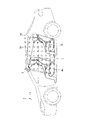
- FIG. 1 is a side view showing a vehicle 1 to which a radio wave sensor 2 according to Embodiment 1 is attached;
- FIG. 1 is a top view showing a vehicle 1 to which a radio wave sensor 2 according to Embodiment 1 is attached;
- FIG. 1 is a configuration diagram showing a radio wave sensor 2 according to Embodiment 1.
- FIG. 2 is a block diagram showing functions of the radio wave sensor 2 according to Embodiment 1.
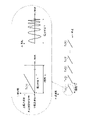
- FIG. 3 is an explanatory diagram showing an example of an FM signal Tx(k) generated by a high frequency signal generation circuit 14;
- FIG. 3 is an explanatory diagram showing an example of FM transmission waves and FM reception waves;
- FIG. 4 is an explanatory diagram showing the relationship between the sweep time T of FM transmission waves and the frequency difference fd ;
- 3 is an explanatory diagram showing an example of virtual antennas 12-1' to 12-8' configured in the radio wave sensor 2;
- FIG. 4 is an explanatory diagram showing an example of a three-dimensional spatial distribution;
- FIG. 3 is an explanatory diagram showing an example of antenna directivity characteristics of transmitting antenna elements 11-1 and 11-2;
- 4 is a block diagram showing functions of another radio wave sensor 2 according to Embodiment 1.
- FIG. 1 is a configuration diagram showing an occupant detection device according to Embodiment 1;
- FIG. 2 is a configuration diagram showing another radio wave sensor 2 according to Embodiment 1.
- FIG. 2 is a configuration diagram showing another radio wave sensor 2 according to Embodiment 1.
- FIG. 2 is a configuration diagram showing another radio wave sensor 2 according to Embodiment 1.
- FIG. 3 is an explanatory diagram showing an example of virtual antennas 12-1' to 12-8' configured in the radio wave sensor 2;
- FIG. 3 is an explanatory diagram showing an example of virtual antennas 12-1' to 12-8' configured in the radio wave sensor 2;
- FIG. 3 is an explanatory diagram showing an example of virtual antennas 12-1' to 12-8' configured in the radio wave sensor 2;
- FIG. FIG. 2 is a side view showing a vehicle in which a radio wave sensor 2 is installed at a position where FM transmission waves radiated from a transmission antenna 11 directly irradiate the ceiling of the vehicle compartment.
- FIG. 2 is a side view showing the vehicle when the radio wave sensor 2 is installed at a position where the FM transmission waves radiated from the transmission antenna 11 are not directly irradiated onto the ceiling of the vehicle compartment.
- FIG. 4 is an explanatory diagram showing rotation of the radio wave sensor 2 in the yz plane;
- FIG. 2 is a configuration diagram showing a radio wave sensor 2 installed in a state rotated clockwise by 90 degrees;
- FIG. 1 is a side view showing a vehicle 1 to which a radio wave sensor 2 according to Embodiment 1 is attached.
- FIG. 2 is a top view showing the vehicle 1 to which the radio wave sensor 2 according to Embodiment 1 is attached. 1 and 2, the x-axis is the axis parallel to the vehicle width direction of the vehicle 1, the y-axis is the axis parallel to the vehicle height direction of the vehicle 1, and the z-axis is the vehicle of the vehicle 1. The axis is parallel to the long direction.
- the radio wave sensor 2 is installed on the ceiling inside the vehicle.
- the radio wave sensor 2 emits radio waves toward the interior of the vehicle 1, receives reflected waves of the radio waves, and detects the passengers 3a, 3b, and 3c present in the interior of the vehicle based on the reflected waves.
- An irradiation range 2a of radio waves emitted from the radio wave sensor 2 includes a region 40 in which a passenger may exist (hereinafter referred to as a “presence possible region”) 40 in the interior of the vehicle 1 .
- the vehicle 1 has front seats and rear seats, and passengers can sit in the front seats or the rear seats. Therefore, the possible existence area 40 is an area including the space occupied by the occupant when the occupant sits on the front seat and the space occupied by the occupant when the occupant sits on the rear seat. .
- the radio wave sensor 2 is installed on the ceiling near the windshield among the ceilings in the passenger compartment.
- the radio wave sensor 2 may be installed on the ceiling on the rear seat side of the windshield.
- the position of installation of the radio wave sensor 2 may be a position on the ceiling side from the heads of the passengers 3a, 3b, 3c existing in the vehicle interior, and the radio wave sensor 2 is installed, for example, in the rearview mirror.
- the occupants 3a, 3b, 3c are present in a possible presence area 40 included in the radio wave irradiation range 2a.
- part of the lower bodies of the passengers 3a, 3b, and 3c is not included in the possible presence area 40.
- FIG. this is only an example, and the entire bodies of the passengers 3a, 3b, and 3c may be included in the possible area 40.
- FIG. The passenger 3a sits in the driver's seat among the front seats of the vehicle.
- the occupant 3b is sitting in the front passenger seat of the vehicle.
- the passenger 3c is sitting in the rear seat of the vehicle.
- the bag 3d is a reflecting object other than the passenger, and is placed substantially in the center of the rear seat.
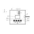
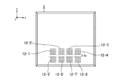
- FIG. 3 is a configuration diagram showing the radio wave sensor 2 according to Embodiment 1.
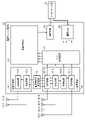
- FIG. 4 is a block diagram showing functions of the radio wave sensor 2 according to the first embodiment.
- the x-axis is an axis parallel to the vehicle width direction of the vehicle 1
- the y-axis is an axis parallel to the vehicle height direction of the vehicle 1
- the z-axis is an axis parallel to the vehicle length direction of the vehicle 1.
- the transmitting antenna 11 is a planar antenna configured on an electronic circuit board.
- the transmitting antenna 11 has a plurality of transmitting antenna elements 11-1 and 11-2 that radiate radio waves toward the possible existence area 40.
- millimeter waves of 60 GHz are used as radio waves radiated from the transmitting antenna 11 .
- the radio wave radiated from the transmitting antenna 11 may be, for example, a quasi-millimeter wave of 24 GHz.
- the installation positions of the transmitting antenna element 11-1 and the transmitting antenna element 11-2 are different from each other in the vehicle height direction of the vehicle 1.
- the receiving antenna 12 is a planar antenna configured on an electronic circuit board and installed on the same plane as the transmitting antenna 11 .
- the same plane here does not mean that the plane on which the transmitting antenna 11 is installed and the plane on which the receiving antenna 12 is installed are strictly the same. Different planes are also included.
- the receiving antenna 12 has a plurality of receiving antenna elements 12 - 1 to 12 - 4 for receiving reflected waves of radio waves radiated from the transmitting antenna 11 .
- the installation positions of the receiving antenna element 12-1, the receiving antenna element 12-2, the receiving antenna element 12-3, and the receiving antenna element 12-4 are different from each other in the vehicle width direction of the vehicle 1.
- the radio wave sensor circuit unit 13 includes a high frequency signal generation circuit 14, a radio wave transmission unit 15, a radio wave reception unit 16, an analog-to-digital conversion circuit (hereinafter referred to as "A/D conversion circuit") 17, an occupant detection unit 18, a communication circuit 19, and a power supply.
- a circuit 20 is provided.
- the high-frequency signal generation circuit 14 generates an FM (Frequency Modulation) signal whose frequency changes over time as a signal for sensing, and outputs the FM signal to each of the radio wave transmitting unit 15 and the radio wave receiving unit 16. .
- the FM-CW (Frequency Modulation-Continuous Wave) system is used as the modulation system, and the high frequency signal generation circuit 14 generates the FM signal.
- the modulation method is not limited to the FM-CW method, and for example, the FCM (Fast-Chirp Modulation) method may be used.
- the high frequency signal generating circuit 14 When the FCM method is used as the modulation method, the high frequency signal generating circuit 14 generates an FCM signal and outputs the FCM signal to the radio wave transmitting section 15 and the radio wave receiving section 16 respectively.
- the radio wave transmission unit 15 has a transmission circuit 15-1 and a transmission circuit 15-2.
- the radio wave transmitting unit 15 radiates radio waves toward the possible existence area 40 from any one of the transmitting antenna elements 11-1 and 11-2. That is, the radio wave transmitting unit 15 sequentially switches one of the transmitting antenna elements 11-1 and 11-2 from which to radiate radio waves.
- the radio wave transmitting section 15 causes the transmitting circuit 15-1 to output the FM signal to the transmitting antenna element 11-1.
- the radio wave transmitting section 15 causes the transmitting circuit 15-2 to output the FM signal to the transmitting antenna element 11-2.
- the transmission circuit 15-1 amplifies the FM signal output from the high-frequency signal generation circuit 14 and outputs the amplified FM signal to the transmission antenna element 11-1, thereby transmitting the signal from the transmission antenna element 11-1 by radio waves. A certain FM transmission wave is radiated toward the possible existence area 40 .
- the transmission circuit 15-2 amplifies the FM signal output from the high-frequency signal generation circuit 14 and outputs the amplified FM signal to the transmission antenna element 11-2, whereby FM transmission is performed from the transmission antenna element 11-2. A wave is radiated toward the viable area 40 .
- the radio wave receiving section 16 has a receiving circuit 16-1, a receiving circuit 16-2, a receiving circuit 16-3 and a receiving circuit 16-4.
- the receiving circuit 16-m extracts a difference fd between the frequency of the FM signal output from the high-frequency signal generating circuit 14 and the frequency of the received signal (hereinafter referred to as "frequency difference").
- the receiving circuit 16 - m generates an intermediate frequency signal IF m having a frequency difference f d and outputs the intermediate frequency signal IF m to the A/D conversion circuit 17 .
- the A/D conversion circuit 17 outputs the digital signal Dm to the occupant detection section 18 .
- the occupant detection unit 18 is realized by, for example, a digital signal processing circuit.
- the occupant detection unit 18 indicates the detection results of the occupants 3a, 3b, 3c present in the passenger compartment, the positions where the occupants 3a, 3b, 3c are seated, and the determination result of whether or not they are adults. It outputs the detection data to the communication circuit 19 .
- a digital signal processing circuit is, for example, a single circuit, a composite circuit, a programmed processor, a parallel programmed processor, an ASIC (Application Specific Integrated Circuit), an FPGA (Field-Programmable Gate Array), or a combination thereof.
- the digital signal processing circuit is not limited to being implemented by dedicated hardware, and may be implemented by software, firmware, or a combination of software and firmware.
- Software or firmware is stored as a program in a computer's memory.
- a computer means hardware that executes a program, for example, a CPU (Central Processing Unit), a central processing unit, a processing unit, an arithmetic unit, a microprocessor, a microcomputer, a processor, or a DSP (Digital Signal Processor). do.
- the communication circuit 19 transfers the detection data output from the occupant detection section 18 to a control unit (not shown) in the vehicle compartment via the interface section 21, which will be described later.
- the power supply circuit 20 receives power supply from a control unit (not shown) or the like via an interface section 21 .
- the power supply circuit 20 distributes the received power as driving power to the high-frequency signal generation circuit 14, the radio wave transmission unit 15, the radio wave reception unit 16, the A/D conversion circuit 17, the occupant detection unit 18, and the communication circuit 19. .
- the interface section 21 is an interface for connecting the radio wave sensor circuit section 13 and a control unit (not shown) or the like.
- FIG. 5 is an explanatory diagram showing an example of the FM signal Tx(k) generated by the high frequency signal generation circuit 14. As shown in FIG. In the FM signal Tx(k) shown in FIG. 5, the initial state of the frequency is the lower limit frequency, and the frequency increases with the passage of time until the frequency reaches the upper limit frequency. In FIG.
- the sweep time T is the time required for the frequency of the FM signal Tx(k) to reach the upper limit frequency from the lower limit frequency
- the frequency bandwidth BW is the frequency difference between the upper limit frequency and the lower limit frequency. be.
- the FM signal Tx(k) is generated K times with a constant period Tc .
- the high-frequency signal generating circuit 14 outputs the FM signal Tx(k) to the transmitting circuits 15-1 and 15-2 of the radio wave transmitting unit 15, and the FM signal Tx(k) to the receiving circuits 16-1 to 16-1 of the radio wave receiving unit 16. Output to 16-4.
- FIG. 5 also shows the amplitude waveform of the FM signal Tx(k).
- the transmission circuits 15-1 and 15-2 alternately output the FM signal Tx(k).
- the transmission circuit 15-1 receives the FM signal Tx(k) from the high-frequency signal generation circuit 14 at the timing of outputting the FM signal Tx(k)
- the transmission circuit 15-1 amplifies the FM signal Tx(k).
- FM signal Tx(k) is output to the transmitting antenna element 11-1.
- the transmission antenna element 11-1 radiates the FM transmission wave toward the possible existence area 40.
- the transmission circuit 15-2 When the transmission circuit 15-2 receives the FM signal Tx(k) from the high frequency signal generation circuit 14 at the timing of outputting the FM signal Tx(k), the transmission circuit 15-2 amplifies the FM signal Tx(k). FM signal Tx(k) is output to the transmitting antenna element 11-2. By outputting the amplified FM signal Tx(k) from the transmission circuit 15-2 to the transmission antenna element 11-2, the FM transmission wave is radiated from the transmission antenna element 11-2 toward the possible existence area 40. .
- the transmission antenna element 11-1 Upon receiving the FM signal Tx(k) from the transmission circuit 15-1, the transmission antenna element 11-1 directs the FM transmission wave whose frequency changes over time toward the possible existence area 40 as shown in FIG. radiate.
- the transmission antenna element 11-2 Upon receiving the FM signal Tx(k) from the transmission circuit 15-2, the transmission antenna element 11-2 radiates an FM transmission wave as shown in FIG.
- FIG. 6 is an explanatory diagram showing an example of FM transmission waves and FM reception waves. FM transmission waves radiated from each of the transmission antenna element 11-1 and the transmission antenna element 11-2 are reflected by the passengers 3a, 3b, and 3c present in the possible existence area 40.
- FIG. FM transmission waves have the property of being transmitted, reflected, or diffracted when they are irradiated onto a structure or the like inside the vehicle.
- the FM transmission wave is transmitted, reflected, or diffracted depends on the material of the structure or the like.
- the front seats and the rear seats are each made of metal or the like for the frame, but cloth or synthetic leather is used for the surface portion, and urethane or the like is used for the interior.
- the FM transmission waves irradiated to the front seats and the like the FM transmission waves that do not hit metal such as the frame penetrate the front seats and the like.
- An FM transmission wave that hits metal such as a framework is reflected by the metal.
- the material of the bag 3d existing in the possible existence area 40 is a material that reflects the FM transmission waves, the FM transmission waves are reflected by the bag 3d.
- the FM received waves which are the reflected waves of the FM transmitted waves reflected by the passengers 3a, 3b, 3c and the bag 3d, are transmitted through the transmitting antenna element 11-1 or the transmitting antenna element 11-2.
- FM transmission waves are received by the receiving antenna elements 12-1 to 12-4 after a lapse of time td after the FM transmission waves are radiated from.
- the frequency difference fd increases in proportion to the distance between the radio wave sensor 2 and the reflecting objects such as the passengers 3a, 3b, 3c.
- FIG. 7 is an explanatory diagram showing the relationship between the sweep time T of the FM transmission wave and the frequency difference fd .
- the receiving circuit 16-m generates a frequency which is the difference between the frequency of the FM signal Tx(k) output from the high-frequency signal generating circuit 14 and the frequency of the received signal Rx(k) output from the receiving antenna element 12-m. Extract the difference f d (k).
- the receiving circuit 16 - m generates an intermediate frequency signal IF m (k) having a frequency difference f d (k) and outputs the intermediate frequency signal IF m (k) to the A/D conversion circuit 17 .
- N N
- Rn is the distance between the radio wave sensor 2 and the passengers 3a, 3b, 3c or the bag 3d
- c is the propagation speed of the radio wave.
- the occupant detection unit 18 searches the first frequency spectrum Sp 1 for the beat frequency Fs 1,n at which the signal intensity reaches the peak value.
- the occupant detection unit 18 calculates the distance Rn by substituting the found beat frequency Fs 1,n into equation (1 ) .
- the occupant detection unit 18 Every time the occupant detection unit 18 calculates the first frequency spectrum Sp 1 , the occupant detection unit 18 Fourier-transforms the first frequency spectrum Sp 1 in the time direction of the FM transmission waves periodically radiated from the transmission antenna 11. to calculate the second frequency spectrum Sp2.
- the signal intensity of the beat frequency Fs2 ,n becomes higher than the signal intensity of the frequencies other than the beat frequency Fs2,n and becomes the peak value of the second frequency spectrum Sp2.
- f0 is the center frequency of the FM signal Tx(k).
- the occupant detection unit 18 searches for the beat frequency Fs2 ,n at which the signal intensity reaches the peak value from the second frequency spectrum Sp2.
- the occupant detection unit 18 calculates the relative velocity vn by substituting the searched beat frequency Fs 2,n into the equation (2).
- the installation positions of the receiving antenna elements 12-1 to 12-4 are different from each other in the vehicle width direction of the vehicle 1.
- d x is the distance between the receiving antenna elements 12-1 to 12-4 in the direction parallel to the vehicle width direction
- ⁇ x,n is the FM received wave for the receiving antenna element 12-m. is the angle of incidence in the xz plane of
- ⁇ is the wavelength of the FM transmitted wave.
- the occupant detection unit 18 calculates the fourth frequency spectrum Sp 4, m , it calculates the fifth frequency spectrum Sp 5 by Fourier transforming the fourth frequency spectrum Sp 4,m .
- the fourth frequency spectrum Sp 4,m is Fourier-transformed over the vehicle width direction (direction parallel to the x-axis), which is the direction in which the receiving antenna elements 12-1 to 12-4 are arranged.
- the signal intensity of the frequency component Fs5 ,n becomes higher than the signal intensity of the frequency components other than the frequency component Fs5,n, and becomes the peak value of the fifth frequency spectrum Sp5.
- the occupant detection unit 18 searches the fifth frequency spectrum Sp5 for the frequency component Fs5 ,n at which the signal intensity reaches the peak value.
- the occupant detection unit 18 calculates the incident angle ⁇ x,n on the xz plane by substituting the searched frequency component Fs 5,n into the following equation (4).
- the radio wave sensor 2 shown in FIG. 3 has four receiving antenna elements 12-1 to 12-4. Further, the radio wave sensor 2 has two transmitting antenna elements 11-1 and 11-2, and the transmitting antenna element 11-1 and the transmitting antenna element 11-2 alternately radiate FM transmission waves. Therefore, as shown in FIG. 8, the radio wave sensor 2 has virtual antennas 12-1' to 12-12 equivalent to four receiving antenna elements 12-1 to 12-4 arranged in two rows in the vehicle height direction. -8' is constructed. In the example of FIG. 8, virtual antennas 12-1' to 12-4' and virtual antennas 12-5' to 12-8' are arranged in the vehicle height direction. The interval in the vehicle height direction between the virtual antennas 12-1' to 12-4' and the virtual antennas 12-5' to 12-8' is d y .
- FIG. 8 is an explanatory diagram showing an example of the virtual antennas 12-1′ to 12-8′ configured in the radio wave sensor 2. As shown in FIG.
- the occupant detection unit 18 detects that the fourth frequency spectrum Sp 4,m is in the vehicle height direction (the direction parallel to the y-axis), which is the direction in which the virtual antennas 12-1′ and the like and the virtual antennas 12-5′ and the like are aligned. ) in the yz plane by substituting the frequency component Fs 5,n obtained by integrating the spectrum value of the received signal Rx(k) into the following equation (5): Calculate the incident angle ⁇ y,n .
- the occupant detection unit 18 is a three-dimensional sensor whose dimensions are the distance R n , the incident angle ⁇ x,n on the xz plane, and the incident angle ⁇ y,n on the yz plane. Generate a spatial distribution. Since the processing itself for generating the three-dimensional spatial distribution is a known technology, detailed description thereof will be omitted.
- FIG. 9 is an explanatory diagram showing an example of a three-dimensional spatial distribution.
- the three-dimensional spatial distribution includes a spatial distribution corresponding to each of the occupants 3a, 3b, and 3c (hereinafter referred to as "passenger spatial distribution") and a spatial distribution corresponding to the bag 3d, which is a reflector other than the occupants (hereinafter referred to as “non-passenger space distribution”).
- passenger spatial distribution a spatial distribution corresponding to each of the occupants 3a, 3b, and 3c
- non-passenger space distribution a spatial distribution corresponding to the bag 3d.
- the shapes of the occupant space distributions 3a', 3b', 3c' and the non-occupant space distribution 3d' are deformed and differ from the actual shapes.
- the occupant detection unit 18 determines whether the spatial distribution is the occupant spatial distribution or the non-occupant spatial distribution based on the shape of the spatial distribution included in the three-dimensional spatial distribution.
- the method of discrimination based on the shape of the spatial distribution may be any method, but for example, using a learning model that learns the respective shapes of the occupant space distribution and the non-occupant space distribution, the three-dimensional space distribution It is conceivable to determine whether the spatial distribution is the occupant spatial distribution or the non-occupant spatial distribution. Further, if the relative velocity vn corresponding to the spatial distribution included in the three-dimensional spatial distribution is greater than, for example, the threshold value Thv , the occupant detection unit 18 determines that the spatial distribution is the occupant spatial distribution.
- the spatial distribution may be determined to be the non-occupant spatial distribution.
- the threshold Thv may be stored in the internal memory of the occupant detection unit 18 or may be given from the outside of the radio wave sensor 2 . Bag 3d is generally stationary. Even if the occupant does not move his or her hands or feet, there is some movement because the occupant is breathing.
- the occupant detection unit 18 determines that the spatial distribution included in the three-dimensional spatial distribution is the occupant spatial distribution, it determines that the occupant is present in the possible presence area 40 . Further, if the occupant detection unit 18 determines that the spatial distribution included in the three-dimensional spatial distribution is the occupant spatial distribution, the distance R n , the incident angle ⁇ x, n, and the incident angle ⁇ y related to the occupant spatial distribution , n , the positions of the occupants present in the occupant space distribution are identified. If the distance Rn from the radio sensor 2 and the incident angles ⁇ x,n and ⁇ y,n with respect to the radio sensor 2 are known, the position of the occupant can be identified.
- the occupant detection unit 18 determines whether the occupants 3a, 3b, 3c present in the vehicle are adults or children based on the size of the occupant space distribution included in the three-dimensional space distribution. determine whether Any method may be used for discrimination based on the size of the occupant space distribution. A mode of determining whether the person is a child or whether the person is a child is conceivable.
- the occupant detection unit 18 detects the detection results of the occupants 3a, 3b, 3c present in the vehicle, the positions where the occupants 3a, 3b, 3c are seated, and whether the occupants 3a, 3b, 3c are adults. It outputs to the communication circuit 19 the determination result indicating whether or not.
- the communication circuit 19 transfers the detection data output from the occupant detection section 18 to a control unit (not shown) in the vehicle compartment via the interface section 21, which will be described later.
- the control unit or the like can recognize the presence of the occupant or the like by receiving the detection data. Therefore, for example, it is possible to check whether an occupant is confined in the vehicle, or whether an infant is left behind in the vehicle. In addition, it is possible to confirm the position where the infant or the like is seated.
- FIG. 10 is an explanatory diagram showing an example of antenna directivity characteristics of the transmitting antenna elements 11-1 and 11-2.
- FIG. 10 shows the antenna gain with respect to the deviation angle from the front direction of the transmitting antenna element 11-1 and the like.
- the horizontal axis indicates the deviation angle [deg]
- the vertical axis indicates the antenna gain [dB].
- the deviation angle in the front direction of the transmitting antenna element 11-1 and the like is 0 [deg].
- the transmitting antenna elements 11-1 and the like have a characteristic that the directional gain peaks in the front direction, and the directional gain decreases as the deviation angle from the front direction increases.
- the antenna directivity characteristics on the horizontal xz plane and the antenna directivity characteristics on the vertical yz plane do not always match.
- An example in which the antenna directivity characteristics and the antenna directivity characteristics in the yz plane do not match is shown.
- the angular range at which the peak of the directional gain falls by 3 [dB] is called the beam width of the transmitting antenna element 11-1 or the like.
- the point where the directional gain is lowered by 3 [dB] from the peak is the point where the transmission power is reduced to half the power at the peak.
- the beam width can be determined by designing the transmitting antenna element 11-1, etc., but has an upper limit and a lower limit.
- the radiation range 2a of the radio wave emitted from the transmitting antenna element 11-1 or the like is determined by the antenna directivity characteristics of the transmitting antenna element 11-1 or the like and the installation position of the radio wave sensor 2 in the vehicle interior.
- the occupant detection unit 18 In order for the occupant detection unit 18 to detect the occupants 3a, 3b, 3c sitting on the seats, the heads including the faces of the occupants 3a, 3b, 3c must be included in the radio wave irradiation range 2a. be. In order to determine whether or not the passengers 3a, 3b, 3c are adults, the upper bodies of the passengers 3a, 3b, 3c below the faces must be included in the radio wave irradiation range 2a.
- the installation position of the radio wave sensor 2 should be closer to the ceiling than the heads of the passengers 3a, 3b, and 3c. position.
- the existence possible area 40 which is an area in which the passenger can exist, is included in the radio wave irradiation range 2a among the areas in the vehicle interior of the vehicle 1.
- FIG. In order for the possible existence area 40 to be included in the radio wave irradiation range 2a, it is desirable that the antenna directivity characteristics of the transmitting antenna element 11-1 and the like be wide-angle.
- the receiving antenna elements 12-1 to 12-4 are required to receive FM received waves, which are reflected waves from the head of the passenger 3a or the like included in the radio wave irradiation range 2a. Therefore, the antenna directivity characteristics of the receiving antenna element 12-1 and the like need to be the same as the antenna directivity characteristics of the transmitting antenna element 11-1 and the like.
- the same characteristic here does not mean that the antenna directivity characteristics of the receiving antenna element 12-1 etc. and the antenna directivity characteristics of the transmitting antenna element 11-1 etc. are strictly the same. It also includes properties that differ in the range without If the radio wave irradiation range 2a includes an obstacle that blocks the FM transmission wave or the FM reception wave, the antenna directivity characteristics of the transmitting antenna element 11-1, etc., or the receiving antenna element 12-1, etc. Antenna directivity is degraded. Therefore, the installation position of the radio wave sensor 2 is determined so that the radio wave irradiation range 2a does not include any obstacles. A room mirror, a room lamp, or the like can be considered as an obstacle.
- the radio wave sensor circuit portion 13 includes an occupant detection portion 18 .
- FIG. 11 is a block diagram showing functions of another radio wave sensor 2 according to the first embodiment.
- FIG. 12 is a configuration diagram showing an occupant detection device according to Embodiment 1.
- FIG. The occupant detection device shown in FIG. 12 includes the radio wave sensor 2 shown in FIG. 11 and the occupant detection section 18 .
- the receiving antenna 12 has four receiving antenna elements 12-1 to 12-4. However, this is only an example, and the receiving antenna 12 may have a plurality of receiving antenna elements, and the receiving antenna 12 may have two receiving antenna elements, three receiving antenna elements, or five or more receiving antenna elements. It may have receive antenna elements. As the number of receiving antenna elements included in the receiving antenna 12 increases, the installation area of the receiving antenna elements needs to be increased, but the resolution of the incident angle ⁇ x,n on the xz plane improves.
- the transmitting antenna 11 has two transmitting antenna elements 11-1 and 11-2. However, this is only an example, and the transmitting antenna 11 may have only one transmitting antenna element, or may have three or more transmitting antenna elements. As the number of transmitting antenna elements included in the transmitting antenna 11 increases, the installation area of the transmitting antenna elements must be increased, but the resolution of the incident angle ⁇ y,n on the yz plane is improved. If the transmission antenna 11 has one transmission antenna element, the occupant detection unit 18 cannot calculate the incident angle ⁇ y,n . If the occupant detection unit 18 cannot calculate the incident angle ⁇ y,n , the above three-dimensional spatial distribution cannot be generated.
- the occupant detection unit 18 can obtain a two-dimensional spatial distribution with the dimensions of the distance R n and the incident angle ⁇ x,n on the xz plane. can be generated. If the occupant detection unit 18 can generate a two-dimensional spatial distribution, it can specify the positions of the occupants 3a, 3b, and 3c on the xz plane.
- FIG. 13 is a configuration diagram showing another radio wave sensor 2 according to Embodiment 1. As shown in FIG. In the example of FIG. 13, the installation positions of the transmission antenna elements 11-1 and 11-2 in the vehicle height direction are different from each other, and the installation positions of the transmission antenna elements 11-1 and 11-2 in the vehicle width direction are different. The installation positions are different from each other.
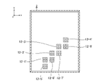
- FIG. 14 is a configuration diagram showing another radio wave sensor 2 according to Embodiment 1.
- the installation position of the receiving antenna element 12-4 in the vehicle width direction is the same as the installation position of the receiving antenna element 12-3 in the vehicle width direction.
- the installation position of the receiving antenna element 12-4 in the vehicle height direction is different from the installation position of each of the receiving antenna elements 12-1 to 12-3 in the vehicle height direction.
- the installation positions of the transmission antenna elements 11-1 and 11-2 in the vehicle height direction are different from each other, and the installation positions of the transmission antenna elements 11-1 and 11-2 in the vehicle width direction are mutually different. different.
- FIG. 15 is a configuration diagram showing another radio wave sensor 2 according to Embodiment 1. As shown in FIG. In the example of FIG. 15, the installation positions of the receiving antenna elements 12-1 to 12-4 in the vehicle width direction are different from each other, and the installation positions of the receiving antenna elements 12-1 to 12-4 in the vehicle height direction are different from each other. The installation positions are different from each other.
- FIG. 16 shows the arrangement of virtual antennas 12-1' to 12-8' when the transmitting antenna elements 11-1 and 11-2 are arranged as shown in FIG.
- FIG. 17 shows the arrangement of virtual antennas 12-1′ to 12-8′ when the transmitting antenna elements 11-1, 11-2 and the receiving antenna elements 12-1 to 12-4 are arranged as shown in FIG. is shown.
- FIG. 18 shows the arrangement of virtual antennas 12-1' to 12-8' when the receiving antenna elements 12-1 to 12-4 are arranged as shown in FIG.
- transmitting antenna elements 11-1 and 11-2 and receiving antenna elements 12-1 to 12-4 are arranged as shown in FIG. -2', 12-7', and 12-8' are arranged three in the vehicle height direction, and the angular resolution is improved as compared with the radio wave sensor 2 shown in FIG.
- the transmission antenna 11 that radiates radio waves toward the possible presence area 40, which is an area in which a passenger can exist, among the areas in the vehicle interior of the vehicle 1, and the radio waves radiated from the transmission antenna 11
- the radio wave sensor 2 is configured to include a receiving antenna 12 having a plurality of receiving antenna elements 12-1 to 12-4 for receiving the reflected waves.
- the installation positions of the plurality of receiving antenna elements 12-1 to 12-4 are different from each other in the vehicle width direction of the vehicle 1. FIG. Therefore, the radio wave sensor 2 can detect all the passengers 3a, 3b, 3c riding in the vehicle 1 and specify the positions of all the passengers 3a, 3b, 3c.
- Embodiment 2 the radio wave sensor 2 is installed at a position where the FM transmission waves emitted from the transmission antenna 11 are not directly irradiated onto the ceiling of the passenger compartment.
- FIG. 19 is a side view showing the vehicle when the radio wave sensor 2 is installed at a position where the FM transmission waves emitted from the transmission antenna 11 are directly irradiated onto the ceiling of the vehicle interior.
- FIG. 20 is a side view showing the vehicle when the radio wave sensor 2 is installed at a position where the FM transmission waves emitted from the transmission antenna 11 are not directly irradiated onto the ceiling of the vehicle interior.
- the radio wave sensor 2 When the radio wave sensor 2 is installed inside the vehicle, if the FM transmission waves radiated from the transmission antenna 11 are directly irradiated onto the ceiling, the FM transmission waves radiated from the transmission antenna 11 may not reach the ceiling inside the vehicle. You may make it adjust the attachment angle of the radio wave sensor 2 so that it may not irradiate directly. For example, as shown in FIG. 21, with the x-axis of the coordinate system of the radio wave sensor 2 as a starting point, the radio wave sensor 2 is rotated in the yz plane, for example, by an angle It should be installed indoors. The angle ⁇ is an angle at which the FM transmission waves emitted from the transmission antenna 11 are not directly irradiated onto the ceiling in the vehicle compartment.
- FIG. 21 is an explanatory diagram showing the rotation of the radio wave sensor 2 within the yz plane.
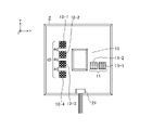
- FIG. 13 is a configuration diagram showing the radio wave sensor 2 installed in a state rotated 90 degrees clockwise. In the example of FIG. 22, the radio wave sensor 2 is installed in a state rotated clockwise by 90 degrees on the xy plane.
- the present disclosure is suitable for radio wave sensors and occupant detection devices.
- 1 Vehicle 2 Radio wave sensor, 2a Radiation range, 3a, 3b, 3c Occupant, 3d Bag, 3a', 3b', 3c' Occupant space distribution, 3d' Non-occupant space distribution, 11 Transmission antenna, 11-1, 11- 2 Transmitting antenna element, 12 Receiving antenna, 12-1 to 12-4 Receiving antenna element, 12-1' to 12-8' Virtual antenna, 13 Radio wave sensor circuit, 14 High frequency signal generation circuit, 15 Radio wave transmitter, 15 -1, 15-2 transmission circuit, 16 radio wave reception unit, 16-1 to 16-4 reception circuit, 17 A/D conversion circuit, 18 occupant detection unit, 19 communication circuit, 20 power supply circuit, 21 interface unit, 30 signal Processing device, 40 Existence possible area.
Landscapes
- Engineering & Computer Science (AREA)
- Remote Sensing (AREA)
- Radar, Positioning & Navigation (AREA)
- Physics & Mathematics (AREA)
- General Physics & Mathematics (AREA)
- Computer Networks & Wireless Communication (AREA)
- Life Sciences & Earth Sciences (AREA)
- Electromagnetism (AREA)
- Environmental & Geological Engineering (AREA)
- Geology (AREA)
- General Life Sciences & Earth Sciences (AREA)
- Geophysics (AREA)
- Geophysics And Detection Of Objects (AREA)
Abstract
Description
第一画像センサから前部座席を見たとき、前部座席の背面側の領域は、第一画像センサの死角となる。後部座席に座っている乗員が、座高が高い大人等であれば、当該乗員の顔等は、第一画像センサの死角の範囲外となり、当該乗員の顔等が、第一画像センサの撮影画像に映る可能性がある。しかし、後部座席に座っている乗員が、座高が低い子供等であれば、当該乗員のほぼ全体が第一画像センサの死角の範囲内となり、当該乗員の顔等が、第一画像センサの撮影画像に映らない可能性がある。当該乗員検知装置では、後部座席に座っている子供等も検知できるようにするため、第二画像センサを設けている。 BACKGROUND ART
When the front seat is viewed from the first image sensor, the area on the back side of the front seat becomes a blind spot for the first image sensor. If an occupant sitting in a rear seat is an adult with a high sitting height, the occupant's face, etc. is outside the range of the blind spot of the first image sensor, and the occupant's face, etc. does not appear in the photographed image of the first image sensor. may appear in However, if the occupant sitting in the back seat is a child with a low sitting height, almost the entire occupant will be within the range of the blind spot of the first image sensor, and the face etc. of the occupant will not be captured by the first image sensor. It may not appear in the image. The occupant detection device is provided with a second image sensor in order to detect a child or the like sitting in the rear seat.
図1は、実施の形態1に係る電波センサ2が取り付けられている車両1を示す側面視図である。
図2は、実施の形態1に係る電波センサ2が取り付けられている車両1を示す上面視図である。
図1及び図2における3次元座標軸のうちのx軸は、車両1の車幅方向と平行な軸、y軸は、車両1の車高方向と平行な軸、z軸は、車両1の車長方向と平行な軸である。
FIG. 1 is a side view showing a
FIG. 2 is a top view showing the
1 and 2, the x-axis is the axis parallel to the vehicle width direction of the
電波センサ2は、車両1の車室内に向けて電波を放射して、当該電波の反射波を受信し、反射波に基づいて、車室内に存在している乗員3a,3b,3cを検知する。
電波センサ2から放射される電波の照射範囲2aは、車両1の車室内の領域のうち、乗員が存在し得る領域(以下「存在可能領域」という)40を含んでいる。
車両1は、前部座席と後部座席とを備えており、乗員は、前部座席、又は、後部座席に座ることが可能である。このため、存在可能領域40は、乗員が前部座席に着座したときに、当該乗員が占有する空間と、乗員が後部座席に着座したときに、当該乗員が占有する空間とを含む領域である。 The
The
An
The
また、電波センサ2の設置位置は、車室内に存在している乗員3a,3b,3cの頭部よりも天井側の位置であればよく、電波センサ2は、例えば、ルームミラーに設置されていてもよい。 In the
Further, the position of installation of the
図1及び図2に示す車両1では、乗員3a,3b,3cの下半身の一部が存在可能領域40に含まれていない。しかし、これは一例に過ぎず、乗員3a,3b,3cの全身が存在可能領域40に含まれていてもよい。
乗員3aは、車両の前部座席のうちの運転席に座っている。
乗員3bは、車両の前部座席のうちの助手席に座っている。
乗員3cは、車両の後部座席に座っている。
カバン3dは、乗員以外の反射物であり、後部座席のほぼ中央に置かれている。 The
In the
The
The
The
The
図4は、実施の形態1に係る電波センサ2の機能を示すブロック図である。
図3における3次元座標軸のうちのx軸は、車両1の車幅方向と平行な軸、y軸は、車両1の車高方向と平行な軸、z軸は、車両1の車長方向と平行な軸である。
送信アンテナ11は、電子回路基板上に構成される平面アンテナである。
送信アンテナ11は、存在可能領域40に向けて電波を放射する複数の送信アンテナ素子11-1,11-2を有している。
図3に示す電波センサ2では、送信アンテナ11から放射される電波として、例えば、60GHzのミリ波が使用される。しかし、これは一例に過ぎず、送信アンテナ11から放射される電波として、例えば、24GHzの準ミリ波が使用されるようにしてもよい。 FIG. 3 is a configuration diagram showing the
FIG. 4 is a block diagram showing functions of the
Of the three-dimensional coordinate axes in FIG. 3, the x-axis is an axis parallel to the vehicle width direction of the
The transmitting
The transmitting
In the
図3に示す電波センサ2では、送信アンテナ素子11-1における車高方向の設置位置が、送信アンテナ素子11-2における車高方向の設置位置よりも高くなっている。 The installation positions of the transmitting antenna element 11-1 and the transmitting antenna element 11-2 are different from each other in the vehicle height direction of the
In the
受信アンテナ12は、送信アンテナ11から放射された電波の反射波を受信する複数の受信アンテナ素子12-1~12-4を有している。 The receiving
The receiving
図3に示す電波センサ2では、受信アンテナ素子12-1~12-4の中で、受信アンテナ素子12-1が最も助手席側に設置されており、受信アンテナ素子12-4が最も運転席側に設置されている。 The installation positions of the receiving antenna element 12-1, the receiving antenna element 12-2, the receiving antenna element 12-3, and the receiving antenna element 12-4 are different from each other in the vehicle width direction of the
In the
図3に示す電波センサ2では、変調方式として、FM-CW(Frequency Modulation-Continuous Wave)方式を使用し、高周波信号発生回路14が、FM信号を生成している。しかし、変調方式は、FM-CW方式に限るものではなく、例えば、FCM(Fast- Chirp Modulation)方式を使用してもよい。変調方式として、FCM方式を使用する場合、高周波信号発生回路14は、FCM信号を生成し、FCM信号を電波送信部15及び電波受信部16のそれぞれに出力する。 The high-frequency
In the
電波送信部15は、送信アンテナ素子11-1及び送信アンテナ素子11-2の中のいずれか1つの送信アンテナ素子から、存在可能領域40に向けて電波を放射させる。
即ち、電波送信部15は、送信アンテナ素子11-1及び送信アンテナ素子11-2の中で、電波を放射させる1つの送信アンテナ素子を順番に切り替える。
電波送信部15は、送信アンテナ素子11-1から電波を放射させるときは、送信回路15-1からFM信号を送信アンテナ素子11-1に出力させる。電波送信部15は、送信アンテナ素子11-2から電波を放射させるときは、送信回路15-2からFM信号を送信アンテナ素子11-2に出力させる。 The radio
The radio
That is, the radio
When radio waves are emitted from the transmitting antenna element 11-1, the radio
送信回路15-2は、高周波信号発生回路14から出力されたFM信号を増幅し、増幅後のFM信号を送信アンテナ素子11-2に出力することによって、送信アンテナ素子11-2から、FM送信波を存在可能領域40に向けて放射させる。 The transmission circuit 15-1 amplifies the FM signal output from the high-frequency
The transmission circuit 15-2 amplifies the FM signal output from the high-frequency
受信回路16-m(m=1,2,3,4)は、受信アンテナ素子12-mによって反射波であるFM受信波が受信されたとき、受信アンテナ素子12-mからFM受信波の受信信号を取得する。
受信回路16-mは、高周波信号発生回路14から出力されたFM信号の周波数と、当該受信信号の周波数との差分(以下「周波数差分」という)fdを抽出する。
受信回路16-mは、周波数差分fdを有する中間周波数信号IFmを生成し、中間周波数信号IFmをA/D変換回路17に出力する。 The radio
The receiving circuit 16-m (m=1, 2, 3, 4) receives the FM received wave from the receiving antenna element 12-m when the receiving antenna element 12-m receives the FM received wave as a reflected wave. Get the signal.
The receiving circuit 16-m extracts a difference fd between the frequency of the FM signal output from the high-frequency
The receiving circuit 16 - m generates an intermediate frequency signal IF m having a frequency difference f d and outputs the intermediate frequency signal IF m to the A/
A/D変換回路17は、デジタル信号Dmを乗員検知部18に出力する。 The A/
The A/
乗員検知部18は、A/D変換回路17から、受信回路16-m(m=1,2,3,4)により受信されたFM受信波に係るデジタル信号Dmを取得する。
乗員検知部18は、デジタル信号Dm(m=1,2,3,4)に基づいて、存在可能領域40に存在している乗員3a,3b,3cを検知する。
また、乗員検知部18は、デジタル信号Dm(m=1,2,3,4)に基づいて、検知した乗員3a,3b,3cが着座している位置を特定する。
さらに、乗員検知部18は、デジタル信号Dmに基づいて、検知した乗員3a,3b,3cが、大人であるのか、子供であるのかを判別する。
乗員検知部18は、車室内に存在している乗員3a,3b,3cの検知結果と、乗員3a,3b,3cが着座している位置と、大人であるか否かの判別結果とを示す検知データを通信回路19に出力する。 The
The
The
The
Further, the
The
デジタル信号処理回路は、専用のハードウェアによって実現されるものに限るものではなく、ソフトウェア、ファームウェア、又は、ソフトウェアとファームウェアとの組み合わせによって実現されるものであってもよい。
ソフトウェア又はファームウェアは、プログラムとして、コンピュータのメモリに格納される。コンピュータは、プログラムを実行するハードウェアを意味し、例えば、CPU(Central Processing Unit)、中央処理装置、処理装置、演算装置、マイクロプロセッサ、マイクロコンピュータ、プロセッサ、あるいは、DSP(Digital Signal Processor)が該当する。 A digital signal processing circuit is, for example, a single circuit, a composite circuit, a programmed processor, a parallel programmed processor, an ASIC (Application Specific Integrated Circuit), an FPGA (Field-Programmable Gate Array), or a combination thereof. realized by
The digital signal processing circuit is not limited to being implemented by dedicated hardware, and may be implemented by software, firmware, or a combination of software and firmware.
Software or firmware is stored as a program in a computer's memory. A computer means hardware that executes a program, for example, a CPU (Central Processing Unit), a central processing unit, a processing unit, an arithmetic unit, a microprocessor, a microcomputer, a processor, or a DSP (Digital Signal Processor). do.
電源回路20は、図示せぬコントロールユニット等から、インタフェース部21を介して、電力の供給を受ける。
電源回路20は、受けた電力を駆動用電力として、高周波信号発生回路14、電波送信部15、電波受信部16、A/D変換回路17、乗員検知部18及び通信回路19のそれぞれに分配する。
インタフェース部21は、電波センサ回路部13と図示せぬコントロールユニット等とを接続するためのインタフェースである。 The
The
The
The
電波センサ2のセンシング用の信号として、各種の変調方式で変調されている信号を用いることが可能であるが、ここではFM-CW方式で変調されている信号を用いる例を説明する。
高周波信号発生回路14は、センシング用の信号として、図5に示すように、時間の経過に伴って周波数が変化するFM信号Tx(k)(k=1,・・・,K)を生成する。Kは、2以上の整数である。
図5は、高周波信号発生回路14により生成されるFM信号Tx(k)の一例を示す説明図である。
図5に示すFM信号Tx(k)では、周波数の初期状態が下限周波数であり、周波数が上限周波数に到達するまで、時間の経過に伴って周波数が増加している。
図5において、掃引時間Tは、FM信号Tx(k)の周波数が、下限周波数から上限周波数に到達するまでの時間であり、周波数帯域幅BWは、上限周波数と下限周波数との差分の周波数である。
図5の例では、FM信号Tx(k)が一定の周期Tcで、K回生成されている。
高周波信号発生回路14は、FM信号Tx(k)を電波送信部15の送信回路15-1,15-2に出力し、FM信号Tx(k)を電波受信部16の受信回路16-1~16-4に出力する。
図5には、FM信号Tx(k)の振幅波形も表されている。 Next, operation of the
A signal modulated by various modulation methods can be used as a signal for sensing by the
The high-frequency
FIG. 5 is an explanatory diagram showing an example of the FM signal Tx(k) generated by the high frequency
In the FM signal Tx(k) shown in FIG. 5, the initial state of the frequency is the lower limit frequency, and the frequency increases with the passage of time until the frequency reaches the upper limit frequency.
In FIG. 5, the sweep time T is the time required for the frequency of the FM signal Tx(k) to reach the upper limit frequency from the lower limit frequency, and the frequency bandwidth BW is the frequency difference between the upper limit frequency and the lower limit frequency. be.
In the example of FIG. 5, the FM signal Tx(k) is generated K times with a constant period Tc .
The high-frequency
FIG. 5 also shows the amplitude waveform of the FM signal Tx(k).
送信回路15-1は、FM信号Tx(k)の出力動作を行うタイミングのとき、高周波信号発生回路14からFM信号Tx(k)を受けると、FM信号Tx(k)を増幅し、増幅後のFM信号Tx(k)を送信アンテナ素子11-1に出力する。
送信回路15-1から増幅後のFM信号Tx(k)が送信アンテナ素子11-1に出力されることによって、送信アンテナ素子11-1から、FM送信波が存在可能領域40に向けて放射させる。
送信回路15-2は、送信回路15-1がFM信号Tx(k)の出力動作を行っているとき、FM信号Tx(k)の出力動作を停止している。
送信回路15-1がFM信号Tx(k)の出力動作を行うタイミングは、例えば、k=1,3,5・・・である。 The transmission circuits 15-1 and 15-2 alternately output the FM signal Tx(k).
When the transmission circuit 15-1 receives the FM signal Tx(k) from the high-frequency
By outputting the amplified FM signal Tx(k) from the transmission circuit 15-1 to the transmission antenna element 11-1, the transmission antenna element 11-1 radiates the FM transmission wave toward the
The transmission circuit 15-2 stops outputting the FM signal Tx(k) while the transmission circuit 15-1 is outputting the FM signal Tx(k).
Timings at which the transmission circuit 15-1 outputs the FM signal Tx(k) are, for example, k=1, 3, 5, .
送信回路15-2から増幅後のFM信号Tx(k)が送信アンテナ素子11-2に出力されることによって、送信アンテナ素子11-2から、FM送信波が存在可能領域40に向けて放射させる。
送信回路15-1は、送信回路15-2がFM信号Tx(k)の出力動作を行っているとき、FM信号Tx(k)の出力動作を停止している。
送信回路15-2がFM信号Tx(k)の出力動作を行うタイミングは、例えば、k=2,4,6・・・である。 When the transmission circuit 15-2 receives the FM signal Tx(k) from the high frequency
By outputting the amplified FM signal Tx(k) from the transmission circuit 15-2 to the transmission antenna element 11-2, the FM transmission wave is radiated from the transmission antenna element 11-2 toward the
The transmission circuit 15-1 stops outputting the FM signal Tx(k) while the transmission circuit 15-2 is outputting the FM signal Tx(k).
Timings at which the transmission circuit 15-2 outputs the FM signal Tx(k) are, for example, k=2, 4, 6, .
送信アンテナ素子11-2は、送信回路15-2からFM信号Tx(k)を受けると、図6に示すようなFM送信波を存在可能領域40に向けて放射する。
図6は、FM送信波及びFM受信波の一例を示す説明図である。
送信アンテナ素子11-1及び送信アンテナ素子11-2のそれぞれから放射されたFM送信波は、存在可能領域40に存在している乗員3a,3b,3cによって反射される。
FM送信波は、車室内の構造物等に照射されると、透過、反射、又は、回折する性質を有している。FM送信波が、透過、反射、又は、回折するかは、構造物等の材質に依存している。
例えば、前部座席及び後部座席のそれぞれは、骨組み等には金属等が使用されているが、表面部分には、布又は合皮等が使用され、内部にはウレタン等が使用されている。前部座席等に照射されたFM送信波のうち、骨組み等の金属等に当たらないFM送信波は、前部座席等を透過する。骨組み等の金属等に当たるFM送信波は、当該金属等によって反射される。
存在可能領域40に存在しているカバン3dの材質が、FM送信波を反射される材質であれば、FM送信波は、カバン3dによって反射される。 Upon receiving the FM signal Tx(k) from the transmission circuit 15-1, the transmission antenna element 11-1 directs the FM transmission wave whose frequency changes over time toward the
Upon receiving the FM signal Tx(k) from the transmission circuit 15-2, the transmission antenna element 11-2 radiates an FM transmission wave as shown in FIG.
FIG. 6 is an explanatory diagram showing an example of FM transmission waves and FM reception waves.
FM transmission waves radiated from each of the transmission antenna element 11-1 and the transmission antenna element 11-2 are reflected by the
FM transmission waves have the property of being transmitted, reflected, or diffracted when they are irradiated onto a structure or the like inside the vehicle. Whether the FM transmission wave is transmitted, reflected, or diffracted depends on the material of the structure or the like.
For example, the front seats and the rear seats are each made of metal or the like for the frame, but cloth or synthetic leather is used for the surface portion, and urethane or the like is used for the interior. Of the FM transmission waves irradiated to the front seats and the like, the FM transmission waves that do not hit metal such as the frame penetrate the front seats and the like. An FM transmission wave that hits metal such as a framework is reflected by the metal.
If the material of the
このとき、FM送信波の周波数とFM受信波の周波数とは、fdの差分がある。周波数差分fdは、電波センサ2と、反射物である乗員3a,3b,3c等との距離に比例して大きくなる。
図7は、FM送信波の掃引時間Tと周波数差分fdとの関係を示す説明図である。 As shown in FIG. 6, the FM received waves, which are the reflected waves of the FM transmitted waves reflected by the
At this time, there is a difference of fd between the frequency of the FM transmission wave and the frequency of the FM reception wave. The frequency difference fd increases in proportion to the distance between the
FIG. 7 is an explanatory diagram showing the relationship between the sweep time T of the FM transmission wave and the frequency difference fd .
受信回路16-mは、高周波信号発生回路14から出力されたFM信号Tx(k)の周波数と、受信アンテナ素子12-mから出力された受信信号Rx(k)の周波数との差分である周波数差分fd(k)を抽出する。
受信回路16-mは、周波数差分fd(k)を有する中間周波数信号IFm(k)を生成し、中間周波数信号IFm(k)をA/D変換回路17に出力する。 When the receiving antenna element 12-m (m=1, 2, 3, 4) receives the FM received wave which is the reflected wave, it outputs the received signal Rx(k) of the FM received wave to the receiving circuit 16-m.
The receiving circuit 16-m generates a frequency which is the difference between the frequency of the FM signal Tx(k) output from the high-frequency
The receiving circuit 16 - m generates an intermediate frequency signal IF m (k) having a frequency difference f d (k) and outputs the intermediate frequency signal IF m (k) to the A/
A/D変換回路17は、デジタル信号Dm(k)を乗員検知部18に出力する。 Upon receiving the intermediate frequency signal IF m (k) from the receiving circuit 16-m (m=1, 2, 3, 4), the A/
The A/
乗員検知部18は、デジタル信号Dm(k)(m=1,2,3,4)に基づいて、存在可能領域40に存在している乗員3a,3b,3cを検知し、乗員3a,3b,3cが着座している位置を特定する。 The
The
乗員検知部18は、A/D変換回路17から、デジタル信号Dm(k)(m=1,2,3,4)を取得する毎に、デジタル信号Dm(k)をフーリエ変換する。
乗員検知部18は、4つのデジタル信号D1(k)~D4(k)のフーリエ変換結果を合成することによって、第1の周波数スペクトルSp1を算出する。
デジタル信号Dm(k)がフーリエ変換されることによって、乗員3a,3b,3c及びカバン3d等の反射物からの反射波の受信信号Rx(k)(k=1,・・・,K)のスペクトル値が、以下の式(1)に示すビート周波数Fs1,n(n=1,・・・,N)に積算される。車両1に乗車している乗員が、3人の乗員3a,3b,3cであり、FM送信波を反射する乗員以外の反射物が、カバン3dだけである場合、N=4である。ここでは、説明の簡単化のため、車両のドア等によって反射される反射波を無視している。
ビート周波数Fs1,nの信号強度は、ビート周波数Fs1,n以外の周波数の信号強度よりも高くなり、第1の周波数スペクトルSp1のピーク値となる。

Every time the
The
By Fourier transforming the digital signal D m (k), a received signal Rx(k) (k=1, . is integrated with the beat frequency Fs 1,n (n=1, . . . , N) shown in the following equation (1). If there are three
The signal intensity of the beat frequency Fs 1,n becomes higher than the signal intensity of the frequencies other than the
乗員検知部18は、探索したビート周波数Fs1,nを、式(1)に代入することによって、距離Rnを算出する。 The
The
第1の周波数スペクトルSp1が、FM送信波の時間方向にフーリエ変換されることによって、反射物からの反射波の受信信号Rx(k)(k=1,・・・,K)のスペクトル値が、電波センサ2と反射物との相対速度vnに対応する、以下の式(2)に示すビート周波数Fs2,nに積算される。
ビート周波数Fs2,nの信号強度は、ビート周波数Fs2,n以外の周波数の信号強度よりも高くなり、第2の周波数スペクトルSp2のピーク値となる。

The spectral value of the received signal Rx(k) (k= 1 , . is integrated with the beat frequency Fs 2,n shown in the following equation (2), which corresponds to the relative velocity vn between the
The signal intensity of the beat frequency Fs2 ,n becomes higher than the signal intensity of the frequencies other than the beat frequency Fs2,n and becomes the peak value of the second frequency spectrum Sp2.
乗員検知部18は、探索したビート周波数Fs2,nを、式(2)に代入することによって、相対速度vnを算出する。 The
The

乗員検知部18は、4つのデジタル信号D1(k)~D4(k)のフーリエ変換結果を合成することによって、第3の周波数スペクトルSp3,mを算出する。
乗員検知部18は、第3の周波数スペクトルSp3,mを算出する毎に、第3の周波数スペクトルSp3,mを、周期的に放射されるFM送信波の時間方向にフーリエ変換することによって、第4の周波数スペクトルSp4,mを算出する。
乗員検知部18は、第4の周波数スペクトルSp4,mを算出する毎に、第4の周波数スペクトルSp4,mをフーリエ変換することによって、第5の周波数スペクトルSp5を算出する。
第4の周波数スペクトルSp4,mが、受信アンテナ素子12-1~12-4が並んでいる方向である車幅方向(x軸と平行な方向)に亘ってフーリエ変換されることによって、反射物からの反射波の受信信号Rx(k)(k=1,・・・,K)のスペクトル値が、x-z平面での入射角θx,nに対応する周波数成分Fs5,nに積算される。
周波数成分Fs5,nの信号強度は、周波数成分Fs5,n以外の周波数成分の信号強度よりも高くなり、第5の周波数スペクトルSp5のピーク値となる。 Every time the
The
Every time the
Every time the
The fourth frequency spectrum Sp 4,m is Fourier-transformed over the vehicle width direction (direction parallel to the x-axis), which is the direction in which the receiving antenna elements 12-1 to 12-4 are arranged. The spectral value of the received signal Rx ( k ) (k=1, . Accumulated.
The signal intensity of the frequency component Fs5 ,n becomes higher than the signal intensity of the frequency components other than the frequency component Fs5,n, and becomes the peak value of the fifth frequency spectrum Sp5.
乗員検知部18は、探索した周波数成分Fs5,nを、以下の式(4)に代入することによって、x-z平面での入射角θx,nを算出する。

The
図8の例では、仮想アンテナ12-1’~12-4’と、仮想アンテナ12-5’~12-8’とが車高方向に並んでいる。
仮想アンテナ12-1’~12-4’と、仮想アンテナ12-5’~12-8’との車高方向の間隔がdyである。
図8は、電波センサ2に構成される仮想アンテナ12-1’~12-8’の一例を示す説明図である。 The
In the example of FIG. 8, virtual antennas 12-1' to 12-4' and virtual antennas 12-5' to 12-8' are arranged in the vehicle height direction.
The interval in the vehicle height direction between the virtual antennas 12-1' to 12-4' and the virtual antennas 12-5' to 12-8' is d y .
FIG. 8 is an explanatory diagram showing an example of the virtual antennas 12-1′ to 12-8′ configured in the

図9は、3次元空間分布の一例を示す説明図である。
3次元空間分布には、乗員3a,3b,3cのそれぞれに対応する空間分布(以下「乗員空間分布」という)と、乗員以外の反射物であるカバン3dに対応する空間分布(以下「非乗員空間分布」という)とが含まれている。
乗員空間分布3a’は、乗員3aに対応する空間分布であり、乗員空間分布3b’は、乗員3bに対応する空間分布であり、乗員空間分布3c’は、乗員3cに対応する空間分布である。
また、非乗員空間分布3d’は、カバン3dに対応する空間分布である。
図9では、乗員空間分布3a’,3b’,3c’及び非乗員空間分布3d’におけるそれぞれの形状がデフォルメされており、実際の形状とは相違している。 As shown in FIG. 9, the
FIG. 9 is an explanatory diagram showing an example of a three-dimensional spatial distribution.
The three-dimensional spatial distribution includes a spatial distribution corresponding to each of the
An occupant
Also, the non-passenger
In FIG. 9, the shapes of the
空間分布の形状に基づく判別の手法は、どのような手法でもよいが、例えば、乗員空間分布及び非乗員空間分布におけるそれぞれの形状を学習している学習モデルを用いて、3次元空間分布に含まれている空間分布が、乗員空間分布であるのか、非乗員空間分布であるのかを判別する態様が考えられる。
また、乗員検知部18は、3次元空間分布に含まれている空間分布に対応する相対速度vnが、例えば、閾値Thvよりも大きければ、当該空間分布が、乗員空間分布であると判別し、相対速度vnが、閾値Thv以下であれば、当該空間分布が、非乗員空間分布であると判別するようにしてもよい。閾値Thvは、乗員検知部18の内部メモリに格納されていてもよいし、電波センサ2の外部から与えられるものであってもよい。
カバン3dは、一般的には静止している。乗員は、手又は足等を動かしていなくても、呼吸をしているので、ある程度の動きがある。 The
The method of discrimination based on the shape of the spatial distribution may be any method, but for example, using a learning model that learns the respective shapes of the occupant space distribution and the non-occupant space distribution, the three-dimensional space distribution It is conceivable to determine whether the spatial distribution is the occupant spatial distribution or the non-occupant spatial distribution.
Further, if the relative velocity vn corresponding to the spatial distribution included in the three-dimensional spatial distribution is greater than, for example, the threshold value Thv , the
また、乗員検知部18は、3次元空間分布に含まれている空間分布が乗員空間分布であると判定すれば、乗員空間分布に係る距離Rn、入射角θx,n及び入射角θy,nのそれぞれから、乗員空間分布に存在している乗員の位置を特定する。電波センサ2からの距離Rnと、電波センサ2に対する入射角θx,n及び入射角θy,nとが分かれば、乗員の位置の特定が可能である。 If the
Further, if the
乗員空間分布の大きさに基づく判別の手法は、どのような手法でもよいが、例えば、大人及び子供におけるそれぞれの乗員空間分布の大きさを学習している学習モデルを用いて、乗員が、大人であるのか、子供であるのかを判別する態様が考えられる。
乗員検知部18は、車室内に存在している乗員3a,3b,3cの検知結果と、乗員3a,3b,3cが着座している位置と、乗員3a,3b,3cが大人であるか否かを示す判別結果とを示す検知データを通信回路19に出力する。 The
Any method may be used for discrimination based on the size of the occupant space distribution. A mode of determining whether the person is a child or whether the person is a child is conceivable.
The
コントロールユニット等は、検知データを受信することで、乗員の存在等を認識することができる。したがって、例えば、乗員の車室内への閉じ込め、車内への幼児の置き去り等を確認することができる。また、幼児等が着座している位置を確認することができる。 The
The control unit or the like can recognize the presence of the occupant or the like by receiving the detection data. Therefore, for example, it is possible to check whether an occupant is confined in the vehicle, or whether an infant is left behind in the vehicle. In addition, it is possible to confirm the position where the infant or the like is seated.
図10では、送信アンテナ素子11-1等の正面方向からのずれ角に対するアンテナ利得を示している。横軸は、ずれ角の角度[deg]を示し、縦軸は、アンテナ利得[dB]を示している。送信アンテナ素子11-1等の正面方向は、ずれ角が0[deg]である。 Here, FIG. 10 is an explanatory diagram showing an example of antenna directivity characteristics of the transmitting antenna elements 11-1 and 11-2.
FIG. 10 shows the antenna gain with respect to the deviation angle from the front direction of the transmitting antenna element 11-1 and the like. The horizontal axis indicates the deviation angle [deg], and the vertical axis indicates the antenna gain [dB]. The deviation angle in the front direction of the transmitting antenna element 11-1 and the like is 0 [deg].
水平面であるx-z平面でのアンテナ指向性特性と、垂直面であるy-z平面でのアンテナ指向性特性とは、必ずしも一致しておらず、図10には、x-z平面でのアンテナ指向性特性と、y-z平面でのアンテナ指向性特性とが一致していない例を示している。
指向性利得のピークから3[dB]だけ下がっている点の角度範囲は、送信アンテナ素子11-1等のビーム幅と呼ばれる。指向性利得のピークから3[dB]だけ下がっている点は、送信電力が、ピークであるときの電力の2分の1に減少している点である。ビーム幅は、送信アンテナ素子11-1等の設計によって決定することが可能であるが、上限及び下限がある。 The transmitting antenna elements 11-1 and the like have a characteristic that the directional gain peaks in the front direction, and the directional gain decreases as the deviation angle from the front direction increases.
The antenna directivity characteristics on the horizontal xz plane and the antenna directivity characteristics on the vertical yz plane do not always match. An example in which the antenna directivity characteristics and the antenna directivity characteristics in the yz plane do not match is shown.
The angular range at which the peak of the directional gain falls by 3 [dB] is called the beam width of the transmitting antenna element 11-1 or the like. The point where the directional gain is lowered by 3 [dB] from the peak is the point where the transmission power is reduced to half the power at the peak. The beam width can be determined by designing the transmitting antenna element 11-1, etc., but has an upper limit and a lower limit.
乗員検知部18が、座席に座っている乗員3a,3b,3cを検知するには、乗員3a,3b,3cの、顔を含む頭部が、電波の照射範囲2aに含まれている必要がある。乗員3a,3b,3cが、大人であるか否かを判別するには、乗員3a,3b,3cの、顔よりも下の上半身が、電波の照射範囲2aに含まれている必要がある。
乗員3a,3b,3cにおける頭部及び上半身のそれぞれが、電波の照射範囲2aに含まれるようにするには、電波センサ2の設置位置は、乗員3a,3b,3cの頭部よりも天井側の位置であることが望ましい。 The
In order for the
In order for the head and upper body of each of the
また、受信アンテナ素子12-1~12-4は、電波の照射範囲2aに含まれている乗員3a等の頭部等からの反射波であるFM受信波を受信する必要がある。このため、受信アンテナ素子12-1等のアンテナ指向性特性は、送信アンテナ素子11-1等のアンテナ指向性特性と同じ特性である必要がある。ここでの同じ特性は、受信アンテナ素子12-1等のアンテナ指向性特性と送信アンテナ素子11-1等のアンテナ指向性特性とが厳密に同一であることを意味するものではなく、実用上問題のない範囲で異なる特性も含まれる。
電波の照射範囲2aに、FM送信波、又は、FM受信波を遮る障害物が含まれている場合、送信アンテナ素子11-1等のアンテナ指向性特性、又は、受信アンテナ素子12-1等のアンテナ指向性特性が劣化する。したがって、電波の照射範囲2aに障害物が含まれないように、電波センサ2の設置位置が決定される。障害物としては、ルームミラー、又は、ルームランプ等が考えられる。 In addition, it is necessary that the existence
Further, the receiving antenna elements 12-1 to 12-4 are required to receive FM received waves, which are reflected waves from the head of the
If the radio
図11は、実施の形態1に係る他の電波センサ2の機能を示すブロック図である。
図11に示す電波センサ2は、電波センサ回路部13が乗員検知部18を備えておらず、通信回路19は、A/D変換回路17から出力されたデジタル信号Dm(k)(m=1,2,3,4)を、インタフェース部21を介して、図12に示す信号処理装置30に送信する。
図12は、実施の形態1に係る乗員検知装置を示す構成図である。
図12に示す乗員検知装置は、図11に示す電波センサ2と、乗員検知部18とを備えている。 In the
FIG. 11 is a block diagram showing functions of another
In the
FIG. 12 is a configuration diagram showing an occupant detection device according to
The occupant detection device shown in FIG. 12 includes the
受信アンテナ12が有する受信アンテナ素子の個数が多いほど、受信アンテナ素子の設置面積を広げる必要があるが、x-z平面での入射角θx,nの分解能が向上する。 In the
As the number of receiving antenna elements included in the receiving
送信アンテナ11が有する送信アンテナ素子の個数が多いほど、送信アンテナ素子の設置面積を広げる必要があるが、y-z平面での入射角θy,nの分解能が向上する。
送信アンテナ11が有する送信アンテナ素子の個数が1つである場合、乗員検知部18は、入射角θy,nを算出することができない。乗員検知部18は、入射角θy,nを算出できない場合、上記の3次元空間分布を生成することができない。
しかし、x-z平面での入射角θx,nを算出できれば、乗員検知部18は、距離Rn及びx-z平面での入射角θx,nのそれぞれを次元とする2次元空間分布を生成することができる。乗員検知部18は、2次元空間分布を生成できれば、x-z平面での乗員3a,3b,3cの位置を特定することができる。 In the
As the number of transmitting antenna elements included in the transmitting
If the
However, if the incident angle θ x,n on the xz plane can be calculated, the
図13は、実施の形態1に係る他の電波センサ2を示す構成図である。
図13の例では、送信アンテナ素子11-1,11-2におけるそれぞれの車高方向の設置位置が互いに異なっており、かつ、送信アンテナ素子11-1,11-2におけるそれぞれの車幅方向の設置位置が互いに異なっている。 In the
FIG. 13 is a configuration diagram showing another
In the example of FIG. 13, the installation positions of the transmission antenna elements 11-1 and 11-2 in the vehicle height direction are different from each other, and the installation positions of the transmission antenna elements 11-1 and 11-2 in the vehicle width direction are different. The installation positions are different from each other.
図14は、実施の形態1に係る他の電波センサ2を示す構成図である。
図14の例では、受信アンテナ素子12-4における車幅方向の設置位置が、受信アンテナ素子12-3における車幅方向の設置位置と同じである。受信アンテナ素子12-4における車高方向の設置位置は、受信アンテナ素子12-1~12-3におけるそれぞれの車高方向の設置位置と異なっている。
また、送信アンテナ素子11-1,11-2におけるそれぞれの車高方向の設置位置が互いに異なっており、かつ、送信アンテナ素子11-1,11-2におけるそれぞれの車幅方向の設置位置が互いに異なっている。 In the
FIG. 14 is a configuration diagram showing another
In the example of FIG. 14, the installation position of the receiving antenna element 12-4 in the vehicle width direction is the same as the installation position of the receiving antenna element 12-3 in the vehicle width direction. The installation position of the receiving antenna element 12-4 in the vehicle height direction is different from the installation position of each of the receiving antenna elements 12-1 to 12-3 in the vehicle height direction.
Further, the installation positions of the transmission antenna elements 11-1 and 11-2 in the vehicle height direction are different from each other, and the installation positions of the transmission antenna elements 11-1 and 11-2 in the vehicle width direction are mutually different. different.
図15は、実施の形態1に係る他の電波センサ2を示す構成図である。
図15の例では、受信アンテナ素子12-1~12-4におけるそれぞれの車幅方向の設置位置が互いに異なっており、かつ、受信アンテナ素子12-1~12-4におけるそれぞれの車高方向の設置位置が互いに異なっている。 In the
FIG. 15 is a configuration diagram showing another
In the example of FIG. 15, the installation positions of the receiving antenna elements 12-1 to 12-4 in the vehicle width direction are different from each other, and the installation positions of the receiving antenna elements 12-1 to 12-4 in the vehicle height direction are different from each other. The installation positions are different from each other.
図16は、送信アンテナ素子11-1,11-2が図13のように配置されている場合の仮想アンテナ12-1’~12-8’の配置を示している。
図17は、送信アンテナ素子11-1,11-2及び受信アンテナ素子12-1~12-4が図14のように配置されている場合の仮想アンテナ12-1’~12-8’の配置を示している。
図18は、受信アンテナ素子12-1~12-4が図15のように配置されている場合の仮想アンテナ12-1’~12-8’の配置を示している。
送信アンテナ素子11-1,11-2及び受信アンテナ素子12-1~12-4が図14のように配置されている場合、仮想アンテナ12-1’~12-8’のうち、仮想アンテナ12-2’,12-7’,12-8’が、車高方向に3つ並ぶことなり、図3に示す電波センサ2よりも、角度分解能が向上する。 16, 17 and 18 are explanatory diagrams showing examples of the virtual antennas 12-1′ to 12-8′ configured in the
FIG. 16 shows the arrangement of virtual antennas 12-1' to 12-8' when the transmitting antenna elements 11-1 and 11-2 are arranged as shown in FIG.
FIG. 17 shows the arrangement of virtual antennas 12-1′ to 12-8′ when the transmitting antenna elements 11-1, 11-2 and the receiving antenna elements 12-1 to 12-4 are arranged as shown in FIG. is shown.
FIG. 18 shows the arrangement of virtual antennas 12-1' to 12-8' when the receiving antenna elements 12-1 to 12-4 are arranged as shown in FIG.
When transmitting antenna elements 11-1 and 11-2 and receiving antenna elements 12-1 to 12-4 are arranged as shown in FIG. -2', 12-7', and 12-8' are arranged three in the vehicle height direction, and the angular resolution is improved as compared with the
実施の形態2では、送信アンテナ11から放射されるFM送信波が、車室内の天井に直接照射されない位置に設置されている電波センサ2について説明する。
In
したがって、マルチパスが生じないように、電波センサ2が設置されていることが望ましい。即ち、図20に示すように、送信アンテナ11から放射されるFM送信波が、車室内の天井に直接照射されない位置に電波センサ2が設置されていることが望ましい。
図19は、送信アンテナ11から放射されるFM送信波が、車室内の天井に直接照射される位置に電波センサ2が設置されている場合の車両を示す側面視図である。
図20は、送信アンテナ11から放射されるFM送信波が、車室内の天井に直接照射されない位置に電波センサ2が設置されている場合の車両を示す側面視図である。 As shown in FIG. 19, when the FM transmission waves emitted from the
Therefore, it is desirable that the
FIG. 19 is a side view showing the vehicle when the
FIG. 20 is a side view showing the vehicle when the
例えば、図21に示すように、電波センサ2における座標系のx軸を起点にして、電波センサ2をy-z平面内で、例えば、角度αだけ回転させた状態で、電波センサ2を車室内に設置すればよい。角度αは、送信アンテナ11から放射されるFM送信波が、車室内の天井に直接照射されないようになる角度である。
図21は、y-z平面内での電波センサ2の回転を示す説明図である。 When the
For example, as shown in FIG. 21, with the x-axis of the coordinate system of the
FIG. 21 is an explanatory diagram showing the rotation of the
車両1の車幅方向と車両1の車高方向とを含む平面であるx-y平面において、電波センサ2が、図22に示すように、90度回転されている状態で設置されている場合、受信アンテナ素子12-1~12-4におけるそれぞれの設置位置は、車両1の車高方向での位置が互いに異なる。また、送信アンテナ素子11-1,11-2におけるそれぞれの設置位置は、車両1の車幅方向での位置が互いに異なる。
図22は、時計回りに90度回転されている状態で設置されている電波センサ2を示す構成図である。
図22の例は、x-y平面において、電波センサ2が、時計回りに90度回転されている状態で設置されている。 In the
When the
FIG. 22 is a configuration diagram showing the
In the example of FIG. 22, the
Claims (11)
- 車両の車室内の領域のうち、乗員が存在し得る領域である存在可能領域に向けて電波を放射する送信アンテナと、
前記送信アンテナから放射された電波の反射波を受信する複数の受信アンテナ素子を有する受信アンテナとを備え、
前記複数の受信アンテナ素子におけるそれぞれの設置位置は、前記車両の車幅方向での位置が互いに異なっていることを特徴とする電波センサ。 a transmission antenna that emits radio waves toward a possible existence area, which is an area in which an occupant may exist, in the area inside the vehicle compartment;
a receiving antenna having a plurality of receiving antenna elements for receiving reflected waves of radio waves radiated from the transmitting antenna;
The radio wave sensor, wherein the installation positions of the plurality of receiving antenna elements are different from each other in the vehicle width direction of the vehicle. - 前記送信アンテナは、前記存在可能領域に向けて電波を放射する複数の送信アンテナ素子を有しており、
前記複数の送信アンテナ素子におけるそれぞれの設置位置は、前記車両の車高方向での位置が互いに異なっていることを特徴とする請求項1記載の電波センサ。 The transmitting antenna has a plurality of transmitting antenna elements that radiate radio waves toward the possible area,
2. The radio wave sensor according to claim 1, wherein the installation positions of the plurality of transmitting antenna elements are different from each other in the vehicle height direction of the vehicle. - 前記車両の車幅方向と前記車両の車高方向とを含む平面において、前記電波センサが、90度回転されている状態で設置されていれば、
前記複数の受信アンテナ素子におけるそれぞれの設置位置は、前記車両の車高方向での位置が互いに異なっており、
前記複数の送信アンテナ素子におけるそれぞれの設置位置は、前記車両の車幅方向での位置が互いに異なっていることを特徴とする請求項2記載の電波センサ。 If the radio wave sensor is installed in a state rotated by 90 degrees on a plane including the vehicle width direction and the vehicle height direction of the vehicle,
The installation positions of the plurality of receiving antenna elements are different from each other in the vehicle height direction of the vehicle,
3. The radio wave sensor according to claim 2, wherein the installation positions of the plurality of transmitting antenna elements are different from each other in the vehicle width direction of the vehicle. - 前記複数の受信アンテナ素子のうち、一部の受信アンテナ素子における前記車両の車幅方向での設置位置が、残りのいずれかの受信アンテナ素子における前記車両の車幅方向での設置位置と同じであることを特徴とする請求項1記載の電波センサ。 Among the plurality of receiving antenna elements, some of the receiving antenna elements have the same installation position in the vehicle width direction as any remaining receiving antenna element in the vehicle width direction. The radio wave sensor according to claim 1, characterized in that there is a
- 前記複数の送信アンテナ素子の中のいずれか1つの送信アンテナ素子から、前記存在可能領域に電波を放射させる電波送信部を備え、
前記電波送信部は、前記複数の送信アンテナ素子の中で、電波を放射させる1つの送信アンテナ素子を順番に切り替えることを特徴とする請求項2記載の電波センサ。 A radio wave transmitting unit that radiates radio waves to the possible area from any one of the plurality of transmitting antenna elements,
3. The radio wave sensor according to claim 2, wherein the radio wave transmitting unit sequentially switches one of the plurality of transmitting antenna elements to radiate radio waves. - 前記送信アンテナと前記受信アンテナとが同一平面に設置されており、前記送信アンテナのアンテナ指向性特性と前記受信アンテナのアンテナ指向性特性とが同じであることを特徴とする請求項1記載の電波センサ。 2. The radio wave according to claim 1, wherein said transmitting antenna and said receiving antenna are installed on the same plane, and antenna directivity characteristics of said transmitting antenna and antenna directivity characteristics of said receiving antenna are the same. sensor.
- 前記送信アンテナ及び前記受信アンテナにおけるそれぞれの設置位置は、前記車室内の天井、又は、前記車室内に存在している乗員の頭部よりも前記天井側の位置であることを特徴とする請求項1記載の電波センサ。 2. The installation position of each of said transmitting antenna and said receiving antenna is a ceiling in said vehicle interior, or a position closer to said ceiling than the head of an occupant present in said vehicle interior. 2. The radio wave sensor according to 1.
- 前記送信アンテナの設置位置は、前記存在可能領域に向けて放射する電波の照射範囲に、当該電波を遮る障害物が含まれない位置であることを特徴とする請求項1記載の電波センサ。 The radio wave sensor according to claim 1, wherein the installation position of the transmitting antenna is a position where an irradiation range of the radio waves radiated toward the possible existence area does not include an obstacle that blocks the radio waves.
- 前記送信アンテナの設置位置は、前記存在可能領域に向けて放射する電波が、前記車室内の天井に直接照射されない位置であることを特徴とする請求項1記載の電波センサ。 The radio wave sensor according to claim 1, wherein the installation position of the transmitting antenna is a position where radio waves radiated toward the possible existence area are not directly irradiated onto the ceiling in the vehicle compartment.
- それぞれの受信アンテナ素子により受信された電波に基づいて、前記存在可能領域に存在している乗員を検知し、前記乗員が着座している位置を特定する乗員検知部を備えたことを特徴とする請求項1から請求項9のうちのいずれか1記載の電波センサ。 An occupant detection unit is provided for detecting an occupant present in the possible presence area based on radio waves received by the respective receiving antenna elements and specifying a position where the occupant is seated. The radio wave sensor according to any one of claims 1 to 9.
- 請求項1から請求項9のうちのいずれか1項記載の電波センサと、
前記電波センサに含まれているそれぞれの受信アンテナ素子により受信された電波に基づいて、前記存在可能領域に存在している乗員を検知し、前記乗員が着座している位置を特定する乗員検知部と
を備えた乗員検知装置。 a radio wave sensor according to any one of claims 1 to 9;
An occupant detection unit that detects an occupant present in the possible presence area based on the radio waves received by the respective receiving antenna elements included in the radio wave sensor, and identifies the position where the occupant is seated. An occupant detection device comprising and .
Priority Applications (5)
| Application Number | Priority Date | Filing Date | Title |
|---|---|---|---|
| JP2022577932A JP7313586B2 (en) | 2021-01-29 | 2021-01-29 | Radio wave sensor and occupant detection device |
| CN202180091370.9A CN116848426A (en) | 2021-01-29 | 2021-01-29 | Radio wave sensor and passenger detection device |
| PCT/JP2021/003134 WO2022162852A1 (en) | 2021-01-29 | 2021-01-29 | Radio wave sensor and occupant detection device |
| US18/035,050 US20240012100A1 (en) | 2021-01-29 | 2021-01-29 | Radio wave sensor and occupant detection device |
| DE112021006950.0T DE112021006950T5 (en) | 2021-01-29 | 2021-01-29 | Radio wave sensor and occupant detection device |
Applications Claiming Priority (1)
| Application Number | Priority Date | Filing Date | Title |
|---|---|---|---|
| PCT/JP2021/003134 WO2022162852A1 (en) | 2021-01-29 | 2021-01-29 | Radio wave sensor and occupant detection device |
Publications (1)
| Publication Number | Publication Date |
|---|---|
| WO2022162852A1 true WO2022162852A1 (en) | 2022-08-04 |
Family
ID=82652795
Family Applications (1)
| Application Number | Title | Priority Date | Filing Date |
|---|---|---|---|
| PCT/JP2021/003134 WO2022162852A1 (en) | 2021-01-29 | 2021-01-29 | Radio wave sensor and occupant detection device |
Country Status (5)
| Country | Link |
|---|---|
| US (1) | US20240012100A1 (en) |
| JP (1) | JP7313586B2 (en) |
| CN (1) | CN116848426A (en) |
| DE (1) | DE112021006950T5 (en) |
| WO (1) | WO2022162852A1 (en) |
Citations (5)
| Publication number | Priority date | Publication date | Assignee | Title |
|---|---|---|---|---|
| JP2001289940A (en) * | 2000-04-10 | 2001-10-19 | Tokai Rika Co Ltd | Occupant detecting system |
| KR20190079060A (en) * | 2017-12-27 | 2019-07-05 | 현대자동차주식회사 | Apparatus for detecting passenger in a vehicle, alarm system and method using it |
| JP2019168379A (en) * | 2018-03-26 | 2019-10-03 | アイシン精機株式会社 | Living body detection system |
| WO2019238575A1 (en) * | 2018-06-11 | 2019-12-19 | Iee International Electronics & Engineering S.A. | Method for robust vehicle occupancy detection with vital sign monitoring |
| JP2020101415A (en) * | 2018-12-20 | 2020-07-02 | パナソニックIpマネジメント株式会社 | Occupant state detection system |
Family Cites Families (5)
| Publication number | Priority date | Publication date | Assignee | Title |
|---|---|---|---|---|
| JP2017181225A (en) * | 2016-03-30 | 2017-10-05 | 本田技研工業株式会社 | Vehicle occupant detection device |
| LU93324B1 (en) * | 2016-11-25 | 2018-05-25 | Iee Sa | Polarimetric Radar System and Method for Detecting and Classifying Vehicle Occupants and Other Objects in a Vehicle Interior |
| EP3392670A1 (en) * | 2017-04-20 | 2018-10-24 | Volvo Car Corporation | A method and system for spatial modelling of an interior of a vehicle |
| CN110891829A (en) * | 2017-07-13 | 2020-03-17 | Iee国际电子工程股份公司 | System and method for radar-based determination of the number of passengers in a passenger compartment of a vehicle |
| JP2019123354A (en) | 2018-01-16 | 2019-07-25 | 株式会社デンソー | Occupant detection device |
-
2021
- 2021-01-29 DE DE112021006950.0T patent/DE112021006950T5/en active Pending
- 2021-01-29 CN CN202180091370.9A patent/CN116848426A/en active Pending
- 2021-01-29 JP JP2022577932A patent/JP7313586B2/en active Active
- 2021-01-29 US US18/035,050 patent/US20240012100A1/en active Pending
- 2021-01-29 WO PCT/JP2021/003134 patent/WO2022162852A1/en active Application Filing
Patent Citations (5)
| Publication number | Priority date | Publication date | Assignee | Title |
|---|---|---|---|---|
| JP2001289940A (en) * | 2000-04-10 | 2001-10-19 | Tokai Rika Co Ltd | Occupant detecting system |
| KR20190079060A (en) * | 2017-12-27 | 2019-07-05 | 현대자동차주식회사 | Apparatus for detecting passenger in a vehicle, alarm system and method using it |
| JP2019168379A (en) * | 2018-03-26 | 2019-10-03 | アイシン精機株式会社 | Living body detection system |
| WO2019238575A1 (en) * | 2018-06-11 | 2019-12-19 | Iee International Electronics & Engineering S.A. | Method for robust vehicle occupancy detection with vital sign monitoring |
| JP2020101415A (en) * | 2018-12-20 | 2020-07-02 | パナソニックIpマネジメント株式会社 | Occupant state detection system |
Also Published As
| Publication number | Publication date |
|---|---|
| JPWO2022162852A1 (en) | 2022-08-04 |
| DE112021006950T5 (en) | 2023-11-16 |
| US20240012100A1 (en) | 2024-01-11 |
| CN116848426A (en) | 2023-10-03 |
| JP7313586B2 (en) | 2023-07-24 |
Similar Documents
| Publication | Publication Date | Title |
|---|---|---|
| US11543511B2 (en) | Radar apparatus and vehicle | |
| US9403501B2 (en) | Carrier system and method thereof | |
| CN107407720B (en) | Radar sensor, radar sensor system and method for determining the position of an object by means of horizontal and vertical digital beam forming for measuring punctiform and planar reflected objects | |
| JP7289070B2 (en) | radar equipment and vehicles | |
| US8717224B2 (en) | Integrated radar apparatus and intergrated antenna apparatus | |
| CN110023780B (en) | Polarized radar system and method for detecting and classifying vehicle occupants and other objects within a vehicle | |
| JP4368852B2 (en) | Radar equipment | |
| US11366229B2 (en) | Range finding method, range finding apparatus, and range finding system | |
| EP2808693B1 (en) | System and method for determining a position of a living being in a vehicle | |
| JP2009031165A (en) | Pulsed radar system | |
| JP2005156337A (en) | On-vehicle radar device | |
| WO2006030832A1 (en) | Monitor | |
| JP6746017B2 (en) | Electronic device, electronic device control method, and electronic device control program | |
| JP2019168379A (en) | Living body detection system | |
| JP2011099683A (en) | Body detector | |
| JP2021026557A (en) | Obstacle detection device | |
| JP3586569B2 (en) | Image synthesizing method using a plurality of reflected radar waves and image radar apparatus mounted on an aircraft using the same | |
| WO2022162852A1 (en) | Radio wave sensor and occupant detection device | |
| EP4281803A1 (en) | Centralized occupancy detection system | |
| WO2023127072A1 (en) | Child presence detection device and child presence detection method | |
| CN113169444B (en) | Radar apparatus for internal automotive radar sensing applications | |
| US20230026131A1 (en) | Method for seat occupancy detection | |
| JP3621679B2 (en) | Vehicle interior object detection device | |
| JP3202969B2 (en) | Wave receiver | |
| JPH04323586A (en) | Airborne radar for aircraft |
Legal Events
| Date | Code | Title | Description |
|---|---|---|---|
| 121 | Ep: the epo has been informed by wipo that ep was designated in this application |
Ref document number: 21922868 Country of ref document: EP Kind code of ref document: A1 |
|
| ENP | Entry into the national phase |
Ref document number: 2022577932 Country of ref document: JP Kind code of ref document: A |
|
| WWE | Wipo information: entry into national phase |
Ref document number: 18035050 Country of ref document: US |
|
| WWE | Wipo information: entry into national phase |
Ref document number: 202180091370.9 Country of ref document: CN |
|
| WWE | Wipo information: entry into national phase |
Ref document number: 112021006950 Country of ref document: DE |
|
| 122 | Ep: pct application non-entry in european phase |
Ref document number: 21922868 Country of ref document: EP Kind code of ref document: A1 |