WO2022162848A1 - Control system, flying body identification method, computer-readable medium, and flying body - Google Patents
Control system, flying body identification method, computer-readable medium, and flying body Download PDFInfo
- Publication number
- WO2022162848A1 WO2022162848A1 PCT/JP2021/003125 JP2021003125W WO2022162848A1 WO 2022162848 A1 WO2022162848 A1 WO 2022162848A1 JP 2021003125 W JP2021003125 W JP 2021003125W WO 2022162848 A1 WO2022162848 A1 WO 2022162848A1
- Authority
- WO
- WIPO (PCT)
- Prior art keywords
- aircraft
- flying object
- information
- unit
- communication terminal
- Prior art date
Links
- 238000000034 method Methods 0.000 title claims description 23
- 238000004891 communication Methods 0.000 claims abstract description 275
- 230000004044 response Effects 0.000 claims description 33
- 230000008569 process Effects 0.000 claims description 13
- 230000008859 change Effects 0.000 description 28
- 238000010586 diagram Methods 0.000 description 17
- RZVHIXYEVGDQDX-UHFFFAOYSA-N 9,10-anthraquinone Chemical compound C1=CC=C2C(=O)C3=CC=CC=C3C(=O)C2=C1 RZVHIXYEVGDQDX-UHFFFAOYSA-N 0.000 description 14
- 230000007246 mechanism Effects 0.000 description 10
- 238000012545 processing Methods 0.000 description 7
- 239000000446 fuel Substances 0.000 description 6
- 230000005540 biological transmission Effects 0.000 description 5
- 230000033001 locomotion Effects 0.000 description 5
- 230000010006 flight Effects 0.000 description 3
- 230000006870 function Effects 0.000 description 3
- 230000007257 malfunction Effects 0.000 description 3
- 238000002485 combustion reaction Methods 0.000 description 2
- UFHFLCQGNIYNRP-UHFFFAOYSA-N Hydrogen Chemical compound [H][H] UFHFLCQGNIYNRP-UHFFFAOYSA-N 0.000 description 1
- 229910000831 Steel Inorganic materials 0.000 description 1
- 238000013459 approach Methods 0.000 description 1
- 238000004590 computer program Methods 0.000 description 1
- 238000001514 detection method Methods 0.000 description 1
- 229910052739 hydrogen Inorganic materials 0.000 description 1
- 239000001257 hydrogen Substances 0.000 description 1
- 238000012423 maintenance Methods 0.000 description 1
- 230000003287 optical effect Effects 0.000 description 1
- 239000013307 optical fiber Substances 0.000 description 1
- 238000012827 research and development Methods 0.000 description 1
- 239000004065 semiconductor Substances 0.000 description 1
- 239000010959 steel Substances 0.000 description 1
Images


Classifications
-
- G—PHYSICS
- G08—SIGNALLING
- G08G—TRAFFIC CONTROL SYSTEMS
- G08G5/00—Traffic control systems for aircraft, e.g. air-traffic control [ATC]
- G08G5/0004—Transmission of traffic-related information to or from an aircraft
- G08G5/0013—Transmission of traffic-related information to or from an aircraft with a ground station
-
- G—PHYSICS
- G08—SIGNALLING
- G08G—TRAFFIC CONTROL SYSTEMS
- G08G5/00—Traffic control systems for aircraft, e.g. air-traffic control [ATC]
- G08G5/0017—Arrangements for implementing traffic-related aircraft activities, e.g. arrangements for generating, displaying, acquiring or managing traffic information
- G08G5/0026—Arrangements for implementing traffic-related aircraft activities, e.g. arrangements for generating, displaying, acquiring or managing traffic information located on the ground
-
- G—PHYSICS
- G08—SIGNALLING
- G08G—TRAFFIC CONTROL SYSTEMS
- G08G5/00—Traffic control systems for aircraft, e.g. air-traffic control [ATC]
- G08G5/0047—Navigation or guidance aids for a single aircraft
- G08G5/0052—Navigation or guidance aids for a single aircraft for cruising
-
- G—PHYSICS
- G08—SIGNALLING
- G08G—TRAFFIC CONTROL SYSTEMS
- G08G5/00—Traffic control systems for aircraft, e.g. air-traffic control [ATC]
- G08G5/0047—Navigation or guidance aids for a single aircraft
- G08G5/0069—Navigation or guidance aids for a single aircraft specially adapted for an unmanned aircraft
-
- G—PHYSICS
- G08—SIGNALLING
- G08G—TRAFFIC CONTROL SYSTEMS
- G08G5/00—Traffic control systems for aircraft, e.g. air-traffic control [ATC]
- G08G5/0073—Surveillance aids
- G08G5/0082—Surveillance aids for monitoring traffic from a ground station
-
- G—PHYSICS
- G08—SIGNALLING
- G08G—TRAFFIC CONTROL SYSTEMS
- G08G5/00—Traffic control systems for aircraft, e.g. air-traffic control [ATC]
- G08G5/003—Flight plan management
- G08G5/0034—Assembly of a flight plan
Definitions
- the present disclosure relates to a control system, an aircraft identification method, a computer-readable medium, and an aircraft.
- Patent Document 1 describes a flying vehicle that automatically performs operations from takeoff in a first takeoff and landing section to departure and arrival in a second takeoff and landing section under the control of a control system that controls the operation of the flying vehicle.
- An operating system is disclosed.
- the object of the present disclosure is to solve such problems, and to provide a control system, an aircraft identification method, a computer-readable medium, and an aircraft capable of identifying an aircraft.
- the control system is a communication unit that receives from the communication terminal an image including the flying object captured by the communication terminal and position information of the communication terminal; an estimation unit that estimates an estimated position of the flying object using the background information and the position information included in the image; an identification unit that identifies the flying object using the estimated position of the flying object; The communication unit transmits information on the identified flying object to the communication terminal.
- the flying object identification method includes: receiving from the communication terminal an image including the aircraft captured by the communication terminal and position information of the communication terminal; estimating an estimated position of the flying object using the background information and the position information contained in the image; identifying the aircraft using the estimated position of the aircraft; A method of transmitting information on the identified flying object to the communication terminal.
- a computer-readable medium comprises: receiving from the communication terminal an image including the aircraft captured by the communication terminal and position information of the communication terminal; estimating an estimated position of the flying object using the background information and the position information contained in the image; identifying the aircraft using the estimated position of the aircraft; transmitting information of the identified flying object to the communication terminal;
- a temporary computer-readable medium storing a program for causing a computer to execute a process.
- the aircraft according to the present disclosure is a device ID control unit that holds the device ID of its own device; A communication unit that transmits the machine ID, When receiving the request signal for the device ID, the communication unit transmits a response signal including the device ID in response to the request.
- FIG. 1 is a block diagram showing the configuration of an aircraft identification system according to a first embodiment
- FIG. 4 is a diagram showing an example of a device ID table according to the first embodiment
- FIG. It is a flow chart which shows operation of a control system concerning a 1st embodiment.
- FIG. 10 is a block diagram showing the configuration of an aircraft identification system according to a second embodiment
- FIG. 3 is a block diagram showing the configuration of an aircraft according to a second embodiment
- FIG. It is a block diagram which shows the structure of the control system concerning 2nd Embodiment.
- It is a flowchart which shows operation
- It is a flowchart which shows operation
- FIG. 11 is a block diagram showing the configuration of an aircraft identification system according to a third embodiment; FIG. It is a flow chart which shows operation of a control system concerning a 3rd embodiment.
- FIG. 11 is a block diagram showing the configuration of an aircraft identification system according to a fourth embodiment;
- FIG. 12 is a diagram showing correspondence between authority levels and aircraft information according to the fourth embodiment;
- It is a flow chart which shows operation of a control system concerning a 4th embodiment.
- FIG. 11 is a block diagram showing the configuration of an aircraft identification system according to a fifth embodiment; It is a flowchart which shows operation
- 3 is a block diagram showing a configuration example of a control device in an aircraft, a control system, and a communication terminal according to each embodiment;
- FIG. 3 is a block diagram showing a configuration example of a control device in an aircraft, a control system, and a communication terminal according to each embodiment;
- FIG. 1 is a block diagram showing the configuration of an aircraft identification system 1 according to the first embodiment.
- An aircraft identification system 1 includes an aircraft 2 and a control system 3 .
- the flying object 2 is, for example, a rotary wing aircraft having rotary wings, such as a drone, an unmanned aerial vehicle (UAV), a flying car, a vertical take-off and landing aircraft (VTOL), and the like. .
- the flying object 2 generates lift and thrust by rotationally driving the rotor blades.
- the aircraft 2 may be an unmanned aircraft on which luggage or the like is loaded, or a manned aircraft on which passengers board.
- the flying object 2 has a machine ID as its own machine identification information. Different flying objects 2 are assigned different body IDs, and no flying body 2 having the same body ID exists.
- the aircraft 2 has a communication unit 14 and an aircraft ID control unit 15 .
- the communication unit 14 and the device ID control unit 15 may be software or modules whose processing is executed by a processor executing a program stored in memory. Alternatively, the communication unit 14 and the device ID control unit 15 may be hardware such as circuits or chips.
- the communication unit 14 transmits the device ID.
- the communication unit 14 performs radio communication with the ground side, that is, the control system 3 .
- the communication unit 14 performs wireless communication with the control system 3 according to a predetermined frequency, transmission power, and the like.
- the communication unit 14 may perform processing in accordance with communication standards defined in 3GPP (3rd Generation Partnership Project) such as 5G, 4G, Wi-Fi (registered trademark), Bluetooth (registered trademark), etc. Processing may be performed in accordance with communication standards.
- the communication unit 14 transmits radio signals to the control system 3 .
- the communication unit 14 receives radio signals from the control system 3 . This enables transmission and reception of data and information between the aircraft 2 and the control system 3 .
- the communication unit 14 transmits the aircraft ID and position information of the aircraft 2 to the control system 3 .
- the communication unit 14 can transmit the aircraft ID not only to the control system 3 but also to communication terminals such as smartphones. In this case, for example, by installing a predetermined application in the smartphone, it is possible to obtain the aircraft ID transmitted by the aircraft 2 .
- the communication unit 14 can transmit the aircraft ID of itself to another aircraft 2, receive the aircraft ID from the other aircraft 2, and can transmit and receive the aircraft ID between the aircraft 2. It is possible.
- the device ID control unit 15 controls the change and transmission of the device ID.
- the device ID control unit 15 holds the device ID of its own device that is changed according to a predetermined change pattern.
- the device ID may be changed, for example, every predetermined time, or may be changed at an arbitrary timing, and the timing of changing the device ID can be set at a timing desired by the user or the like.
- the aircraft ID may change as the number of flights increases, or may change after multiple flights.
- the device ID control unit 15 creates a plurality of device IDs in advance as described in the device ID table of FIG. 2, and changes the device IDs at predetermined time intervals.
- the communication unit 14 may transmit the device ID table stored by the device ID control unit 15 to the control system 3 .
- the aircraft ID control unit 15 can share the aircraft ID change pattern with the control system 3 that controls the flight of the aircraft.
- the communication unit 14 may receive the aircraft ID table from the control system 3 .
- the aircraft ID change pattern of the aircraft 2 is shared between the aircraft 2 and the control system 3 .
- the aircraft ID at the start of flight (0 minutes after the start of flight) is #0
- the aircraft ID at 10 minutes after the start of flight is #1
- the aircraft ID at 20 minutes after the start of flight is #2
- Thirty minutes after the start of flight the aircraft ID is #3.
- the device ID table in FIG. 2 is an example, and any device ID may be generated.
- the aircraft ID control unit 15 or the control system 3 may generate an aircraft ID using an algorithm, a random number generation function, or the like.
- the machine ID may be a randomly generated ID or an ID that changes according to at least one of the number of flights and the flight time of the machine.
- the aircraft 2 flies according to a predetermined flight plan while communicating wirelessly with the control system 3.
- the flying object 2 can autonomously fly along a flight path from a takeoff place to a landing place.
- the aircraft 2 takes off from a takeoff and landing facility and flies along a flight route based on a flight plan.
- the flying object 2 lands at the landing site after flying to the landing site corresponding to the destination.
- a flight path is a three-dimensional path from a takeoff site to a landing site.
- Pre-designated take-off and landing facilities can be used for take-off and landing locations. Note that the take-off location and landing location may be arbitrary locations as long as there is space for landing. Of course, the takeoff/landing place for takeoff and the takeoff/landing place for landing may be the same place.
- the operation of the flying object 2 can be switched between autopilot or manual operation by the operator.
- the flying object 2 can be configured to operate automatically and switch to manual operation in an emergency because the operator is required to have advanced maneuvering skills in an area with many obstacles, such as an urban area.
- the control system 3 is an operation management/control system.
- the control system 3 is a hardware device (computer device) for performing flight management and air traffic control of the aircraft 2, and is installed in the flight control center.
- the control system 3 is not limited to a single physical device. For example, a plurality of processors may work together to perform processing described later.
- control system 3 may be provided in an air traffic control center that communicates with a plurality of operation control centers.
- control system 3 of the flight control center and the control system 3 of the air traffic control center communicate with each other, so that the aircraft 2 can be controlled over a wide area.
- the control system 3 has a communication unit 4 and an identification unit 5.
- the communication unit 4 and the identification unit 5 may be software or modules whose processing is executed by a processor executing a program stored in memory.
- the communication unit 4 and the identification unit 5 may be hardware such as circuits or chips.
- the communication unit 4 acquires the aircraft ID transmitted from the aircraft 2 and the position information of the aircraft 2 . Also, the communication unit 4 acquires the aircraft ID and position information of the aircraft 2 at different timings.
- the identification unit 5 identifies the flying object 2 using the aircraft ID received from the flying object 2 .
- the identification unit 5 may be configured to hold in advance a table in which aircraft IDs and aircraft are associated, refer to the table, and extract aircraft associated with the received aircraft ID.
- the communication unit 4 may acquire different aircraft IDs from the aircraft 2 at different timings.
- the identification unit 5 determines that the machine ID different from the first machine ID is based on the change between the position information acquired together with the first machine ID and the position information acquired together with the machine ID different from the first machine ID. , indicates the aircraft 2 associated with the first aircraft ID.
- a change in position information may be indicated by using, for example, the distance between position information acquired at different timings. For example, even if the identification unit 5 determines that the aircraft ID different from the first aircraft ID indicates the aircraft 2 associated with the first aircraft ID when the change in the position information is within a predetermined range, good.
- FIG. 3 is a flow chart showing the operation of the control system 3 according to the first embodiment.
- the communication unit 4 acquires the first aircraft ID and position information of the aircraft 2 (S1).
- the initial machine ID is called the first machine ID
- the changed machine ID is called the second machine ID.
- the identification unit 5 identifies the aircraft 2 using the first aircraft ID (S2).
- the control system 3 communicates with the aircraft 2 that transmits the first aircraft ID, and performs operation management and air traffic control of the aircraft 2 .
- the control system 3 causes the identification unit 5 to The operation management and air traffic control of the aircraft 2 transmitting the identified first aircraft ID are continued.
- the identification unit 5 identifies the first aircraft ID. Based on the change between the position information at the time of acquisition and the position information at the time of acquiring the second aircraft ID, the aircraft 2 transmitting the second aircraft ID transmits the first aircraft ID. It is determined whether or not it is the same as the aircraft 2 . For example, the identification unit 5 determines whether the change between the position information when the first machine ID is acquired and the position information when the second machine ID is acquired is equal to or less than a threshold (S4). .
- the identification unit 5 identifies the flying object 2 transmitting the second aircraft ID. , is determined to be the same flying object 2 as the flying object 2 that transmitted the first aircraft ID (S5).
- a preset threshold value for example, 50 m
- the identifying unit 5 identifies the aircraft 2 transmitting the second aircraft ID as the first aircraft.
- the flying object 2 is identified as different from the flying object 2 that transmitted the ID (S6).
- the air traffic control system 3 identifies the aircraft 2 transmitting the first aircraft ID and the aircraft 2 transmitting the second aircraft ID as different aircraft 2, and performs flight management and air traffic control. conduct.
- the aircraft 2 according to the first embodiment can improve security by changing the aircraft ID.
- the control system 3 will not be able to identify the flying object 2, so there is also a problem that the safety of flight may be lost.
- the control system 3 according to the first embodiment can identify the flying object 2 by using the position information of the flying object 2 even when different aircraft IDs are acquired at different timings. can be done. As a result, the control system 3 can identify or specify the aircraft 2 that changes the transmitted aircraft ID in consideration of security.
- FIG. 4 is a block diagram showing the configuration of an aircraft identification system 100 according to the second embodiment.
- the aircraft identification system 100 includes an aircraft 20 and a control system 30 .
- FIG. 5 is a block diagram showing the configuration of the aircraft 20 according to the second embodiment.
- the aircraft 20 includes a flight control section 11 , a drive mechanism 12 , a sensor 13 , a communication section 14 , a body ID control section 15 , a display section 16 and a battery 17 .
- the same reference numerals are given to the same components as in the first embodiment, and detailed description thereof will be omitted as appropriate.
- the flight control unit 11 controls each component that constitutes the aircraft 20 .
- the drive mechanism 12 has rotary wings and their motors, and generates lift and thrust for flight.
- the flight control unit 11 outputs drive signals for controlling the drive mechanism 12 .
- the flight control unit 11 controls the drive mechanism 12 so that the drive mechanism 12 drives each rotor blade independently.
- the flight control unit 11 stores flight plans in a memory or the like.
- the flight control unit 11 may store a flight plan received from the control system 30 in its memory, or may store a flight plan input by the user of the aircraft 20 in its memory.
- the flight control unit 11 controls the drive mechanism 12 so as to fly according to the flight plan.
- the flight control unit 11 flies by controlling the drive mechanism 12 so that the aircraft 20 approaches the flight path when the position of the aircraft moves away from the flight path due to wind or the like.
- the flight control unit 11 can detect the position of the flying object 20 by using the sensor 13 .
- the flight control section 11 controls the drive mechanism 12 based on the detection result of the sensor 13 .
- the sensor 13 detects information regarding the flight state of the aircraft 20 .
- the sensor 13 has, for example, a gyro sensor that detects the attitude of the aircraft, a position sensor that detects the position of the aircraft, and the like.
- a satellite positioning sensor such as GPS (Global Positioning System) can be used.
- the flight control unit 11 identifies the position of the aircraft based on the information acquired by the sensor 13 . Specifically, the flight control unit 11 identifies the three-dimensional position of the aircraft 20 based on positioning information received by the sensor 13 from a plurality of satellites, for example.
- the communication unit 14 transmits the aircraft ID and position information about the position specified by the flight control unit 11 .
- the number of sensors 13 is not limited to one, and a plurality of sensors 13 may be used.
- the aircraft 20 may be provided with a display unit 16 for showing passengers the flight status, congestion during flight, aircraft information, and the like.
- the display content displayed on the display unit 16 may be changed according to the information about the flying object 20 .
- the display content displayed on the display unit 16 may be changed according to information as to whether the flying object 20 is a manned aircraft or an unmanned aircraft.
- the display content displayed on the display unit 16 may be changed according to information as to whether the flying object 20 is in automatic operation or manual operation.
- the display unit 16 may be omitted.
- the battery 17 supplies power to each device that constitutes the aircraft 20 .
- the flying object 20 can fly while communicating with the control system 30 by providing the components described above.
- FIG. 6 is a block diagram of the control system 30 according to the second embodiment.
- the control system 30 includes a communication unit 4 , an identification unit 5 , a generation unit 6 , a storage unit 7 and an estimation unit 8 .
- the same components as in the first embodiment are denoted by the same reference numerals, and detailed description thereof will be omitted as appropriate.
- the communication unit 4 performs wireless communication with the aircraft 20 and acquires aircraft information including the aircraft ID and position information of the aircraft 20 .
- the aircraft information may include performance information regarding the performance of the aircraft 20 .
- the performance information includes data on the weight, size, flight time, turning ability, wind resistance, flight speed, and flight altitude of the aircraft 20 .
- the performance information may include data regarding remaining battery capacity and fuel level during flight.
- the performance information may include information indicating whether the aircraft is manned or unmanned.
- the aircraft information may include information indicating whether or not the aircraft is an emergency aircraft for police, fire, ambulance, or the like.
- the communication unit 4 performs wireless communication with the flying object 20 according to a predetermined frequency, transmission output, and the like.
- the communication unit 4 may perform processing in accordance with communication standards such as 5G and 4G defined by 3GPP, and processing in accordance with communication standards such as Wi-Fi (registered trademark) and Bluetooth (registered trademark). may be performed.
- the communication unit 4 transmits radio signals to the aircraft 20 .
- the communication unit 4 receives radio signals from the aircraft 20 . This enables transmission and reception of data and information between the aircraft 20 and the control system 30 .
- the generation unit 6 generates a flight plan including a flight route and a flight schedule based on the scheduled takeoff time (scheduled takeoff time) of the aircraft 20 acquired by the communication unit 4 and the movement information regarding the destination.
- the scheduled take-off time may be the current time or the time registered in the schedule in advance.
- the scheduled take-off time and destination may be information directly input into the control system 30 by the user of the aircraft 20 or the user of the control system 30 .
- the destination may be a place name, facility name, address, coordinates (latitude and longitude), and the like. Also, the destination may be the ID of the takeoff/landing facility itself, and the movement information may include intermediate points between the takeoff location and the landing location.
- a flight route is a travel route from the takeoff site to the landing site corresponding to the destination.
- the flight path is information indicating the trajectory of the target position that the flying object 20 passes through. Further, on the flight route, each target position may be associated with an estimated flight time.
- a flight path may be, for example, a set of three-dimensional coordinates indicating target positions. Specifically, the flight path may be data in which three-dimensional coordinates are arranged in chronological order. A flight path is generated by connecting the three-dimensional coordinates.
- the generation unit 6 may generate a flight route based on the performance information. For example, the generation unit 6 generates a flight path so as to satisfy the performance indicated by the performance information.
- the performance information includes the weight, size, flight time, turning ability, wind resistance, flight speed, and flight altitude of the aircraft 20 .
- the performance information may include the current battery level and fuel level. For example, when power is provided by an electric motor, the remaining battery level is included in the performance information, and when power is provided by an internal combustion engine, the remaining amount of fuel such as gasoline is included in the performance information. Alternatively, when a fuel cell is used as the battery 17, the remaining amount of fuel such as hydrogen is included in the performance information. When the internal combustion engine and the electric motor are used together as motive power, both the remaining battery level and the remaining fuel level may be included in the performance information.
- the generation unit 6 For example, if the performance information includes a possible flight time, the generation unit 6 generates a flight route so that the possible flight time is not exceeded. Specifically, the generating unit 6 shortens the flight distance of the aircraft 20 with a short available flight time to generate a flight route that does not exceed the available flight time. As a matter of course, the generation unit 6 can generate a flight route so as to satisfy performance other than the available flight time.
- the communication unit 4 transmits the generated flight plan to the aircraft 20 .
- the storage unit 7 stores the aircraft information acquired from the aircraft 20 and the flight plan generated by the generation unit 6.
- the storage unit 7 also stores an aircraft ID table that indicates the change pattern of the aircraft ID transmitted by the aircraft 20 .
- the identification unit 5 identifies the acquired aircraft based on the aircraft ID table stored in the storage unit 7 in addition to the change between the position information acquired at different timings. Identify the aircraft 20 associated with the ID. Further, the identification unit 5 may identify the flying object 20 by referring to the flight plan in addition to the aircraft ID and position information. The identifying unit 5 compares the position information of the flying object 20 in flight with the flight plan of the flying object 20 to improve the accuracy of identifying the flying object 20 .
- the estimating unit 8 estimates the estimated position of the flying object 20 in flight based on the position information and flight plan of the flying object 20 at the time of communication disconnection when wireless communication between the control system 30 and the flying object 20 is cut off. .
- the estimating unit 8 calculates the speed and direction of the flying object 20 from the position information up to the time when the communication is cut off, and uses the flight route and flight schedule of the flight plan after the time when the communication is cut off to calculate the flying object 20. Estimate the estimated position of .
- the identifying unit 5 identifies the flying object 20 by comparing the aircraft ID of the flying object 20 at the estimated position with the aircraft ID based on the aircraft ID table. Furthermore, the identifying unit 5 identifies the flying object 20 by comparing the position of the flying object 20 when communication is restored with the estimated position of the flying object 20 at the timing when communication is restored.
- FIG. 7 is a flow chart showing the operation of the control system 30 according to the second embodiment. Since S11 to S14 in FIG. 7 are the same as S1 to S4 in FIG. 3, description thereof is omitted. As in FIG. 3, in order to distinguish the machine IDs, the initial machine ID is called the first machine ID, and the changed machine ID is called the second machine ID.
- the identification unit 5 When the change between the position information when the first machine ID is acquired and the position information when the second machine ID is acquired is equal to or less than a threshold value (S14, YES), the identification unit 5 causes the storage unit 7 to store Refers to the machine ID change pattern.
- the change between position information being equal to or less than a threshold means that the amount of change between position information is equal to or less than a threshold.
- the identification unit 5 determines whether the second aircraft ID is the same as the aircraft ID specified by the aircraft ID change pattern of the aircraft 20 that transmitted the first aircraft ID (S15).
- the identification unit 5 determines that the aircraft 20 transmitting the second aircraft ID has transmitted the first aircraft ID.
- the flying object 20 is identified as a different flying object 20 (S18). If the second aircraft ID is the same as the aircraft ID specified by the change pattern (S15, YES), the identification unit 5 refers to the flight plan stored in the storage unit 7, and determines the second aircraft ID acquired. It is determined whether the position is the position in the flight plan of the aircraft 20 transmitting the first aircraft ID (S16). When the position at which the second aircraft ID was acquired does not exist in the flight plan (S16, NO), the identification unit 5 identifies it as a different aircraft 20 (S18).
- the identification unit 5 identifies the aircraft 20 transmitting the second aircraft ID and the first aircraft ID. It is determined that the transmitting flying object 20 is the same flying object 20 (S17). Also, although FIG. 7 shows that the processes are executed in the order of steps S14, S15, and S16, the order of steps S14, S15, and S16 may be changed. For example, the control system 30 may execute the process of step S15 and then execute the process of step S14 or S16, or execute the process of step S16 and then execute the process of step S14 or S15. good too.
- FIG. 8 is a flowchart showing the operation of the control system 30 when communication with the aircraft 20 is restored. Since S21 to S22 in FIG. 8 are the same as S1 to S2 in FIG. 3, description thereof is omitted. As in FIG. 3, in order to distinguish the machine IDs, the initial machine ID is called the first machine ID, and the changed machine ID is called the second machine ID.
- the estimating unit 8 determines the position of the flying object 20 in flight based on the position information of the flying object 20 at the time of communication disconnection and the flight plan stored in the storage unit 7.
- An estimated position is estimated (S23). For example, when the communication unit 4 does not receive a radio signal from the aircraft 20 for a predetermined period of time, or when the communication unit 4 does not receive a response signal to the radio signal transmitted by the communication unit 4, the estimation unit 8 determines whether the communication unit 4 and the aircraft 20 may be determined to have been disconnected.
- the identification unit 5 identifies the aircraft 20 using the first aircraft ID.
- the identification unit 5 identifies the estimated position of the flying object 20 estimated by the estimation unit 8 and the second aircraft ID. is compared with the location information when it was acquired.
- the identification unit 5 identifies the aircraft as a different flying object 20 (S28).
- the identification section 5 refers to the machine ID change pattern stored in the storage section 7.
- the identification unit 5 determines whether the second aircraft ID is the same as the aircraft ID specified by the aircraft ID change pattern of the aircraft 20 that transmitted the first aircraft ID (S26). When the second aircraft ID is different from the aircraft ID specified by the change pattern (S26, NO), the identification unit 5 determines that the aircraft 20 transmitting the second aircraft ID has transmitted the first aircraft ID. The flying object 20 is identified as a different flying object 20 (S28). If the second aircraft ID is the same as the aircraft ID specified by the change pattern (S26, YES), the identification unit 5 transmits the aircraft 20 transmitting the second aircraft ID and the first aircraft ID. It is determined that the flying object 20 that was flying is the same flying object 20 (S27). Also, although FIG. 8 shows that the processes are executed in the order of steps S25 and S26, the order of steps S25 and S26 may be changed. For example, the control system 30 may execute the process of step S26 and then execute the process of step S25.
- the control system 30 identifies the flying object 20 by using the change between the position information of the flying object 20, the change pattern of the aircraft ID, and the flight plan. can be done. Furthermore, even if the aircraft ID of the aircraft 20 is changed when communication with the aircraft 20 is cut, the control system 30 compares the position information of the aircraft 20 at the time of communication restoration with the estimated position. , and the change pattern of the aircraft ID, it is possible to determine whether or not the second aircraft ID indicates the aircraft 20 . This allows the control system 30 to identify the flying object 20 even if the flying object 20 changes its body ID to improve security.
- An aircraft identification system 101 according to the third embodiment includes an aircraft 2 , a control system 31 and a communication terminal 40 .
- the aircraft 2 includes a communication section 14 and an aircraft ID control section 15 .
- the control system 31 includes a communication section 4 , an identification section 5 and an estimation section 8 .
- An aircraft identification system 101 according to the third embodiment is a system that identifies an aircraft 2 using a communication terminal 40 .
- the same components as in the first and second embodiments are denoted by the same reference numerals, and detailed description thereof will be omitted as appropriate.
- the communication terminal 40 is, for example, a smartphone, and has a communication function and a photographing function.
- the communication terminal 40 can communicate with the control system 31 .
- the communication terminal 40 may communicate with the control system 31 via a mobile network managed by a telecommunications carrier or the Internet.
- a user of the communication terminal 40 can acquire information on the flying object 2 by transmitting an inquiry message containing an image including the flying object 2 and position information of the communication terminal 40 to the control system 31 .
- the user of the communication terminal 40 takes an image including the flying object 2 when the flying object 2 is emitting noise or when a suspicious flying object 2 is flying, and inquires the control system 31. I do.
- the communication terminal 40 can acquire the aircraft ID by directly communicating with the aircraft 2 by radio.
- a communication method such as Bluetooth (registered trademark) may be used.
- the communication terminal 40 requests the aircraft ID from the flying object 2, and if it cannot obtain a response from the flying object 2, it determines that the flying object 2 is a suspicious object, and You may report to the police that a suspicious aircraft is flying and staying.
- the communication terminal 40 may transmit a message to the aircraft 2 in addition to the aircraft ID request.
- the message may be, for example, the content that the noise during the flight is too loud or the purpose of the stay.
- the communication terminal 40 can acquire circumstances such as the purpose of stay of the flying object 2 when there is a response from the flying object 2 .
- the communication terminal 40 cannot obtain a response from the flying object 2, it determines that the flying object 2 is a suspicious object, and reports to the police that a suspicious object is flying and staying around the position of the communication terminal 40. may be notified to
- the communication unit 14 of the aircraft 2 When the communication unit 14 of the aircraft 2 receives a request signal for the aircraft ID from, for example, the control system 31, the communication terminal 40, or another aircraft 2, it transmits a response signal including the aircraft ID in response to the request. Note that whether or not to respond to the machine ID request may be set in advance according to the request source. Alternatively, the user of the aircraft 2 may decide whether or not to respond to the request for the aircraft ID and the content of the response.
- the communication unit 4 of the control system 31 receives from the communication terminal 40 an image including the aircraft 2 photographed by the communication terminal 40 and the position information of the communication terminal 40 .
- the estimation unit 8 estimates the estimated position of the flying object 2 using the background information and position information included in the received image.
- the estimation unit 8 identifies the position of the communication terminal 40 at the time of image capturing from the position information of the communication terminal 40 .
- the estimation unit 8 estimates the position of the aircraft 2 near the position of the communication terminal 40 from the background information included in the received image.
- the estimation unit 8 may estimate the position of a building, steel tower, mountain, river, sea, or the like, which is background information, using map information or the like.
- the estimation unit 8 may estimate the position of the aircraft 2 from the background image without using the position information of the communication terminal 40. good. Furthermore, the estimation unit 8 may estimate the position of the flying object 2 by estimating the distance between the flying object 2 in the image and the background information. The estimating unit 8 also determines the shooting direction of the communication terminal 40 , that is, the angle of the communication terminal 40 when the communication terminal 40 is held up toward the sky to shoot the flying object 2 , and the like. May be used for estimation.
- the communication unit 4 sends, via a mobile network managed by a telecommunications carrier, a communication terminal 40 existing in a predetermined area, a photographed image of the sky above the predetermined area, or the position of the communication terminal 40 that has photographed the image. You can also request information.
- the identifying unit 5 identifies the flying object 2 using the estimated position of the flying object 2 estimated by the estimating unit 8 .
- the identifying unit 5 identifies the flying object 2 at the estimated position, for example, by comparing the position information of the flying object 2 under control with the estimated position. Specifically, when the distance between the position of the flying object 2 under control and the estimated position is shorter than a predetermined distance, the identifying unit 5 determines that the flying object 2 existing at the estimated position It may be identified as the aircraft 2 under control.
- the communication unit 4 transmits information on the identified flying object 2 to the communication terminal 40 .
- the communication unit 4 transmits information such as the aircraft ID, aircraft information, and destination of the identified flying object 2 to the communication terminal.
- the user of the communication terminal 40 can acquire the information of the aircraft 2 .
- the aircraft ID of the aircraft 2 may be associated in advance with information such as aircraft information and destination.
- the communication unit 4 may transmit a request signal requesting the aircraft ID to the aircraft 2 at the estimated position of the aircraft 2 estimated by the estimation unit 8 using directional radio waves.
- the identification unit 5 can identify the aircraft 2 using the aircraft ID included in the response signal when the communication unit 4 receives the response signal to the request signal.
- the identifying unit 5 may identify the flying object 2 corresponding to the aircraft ID by referring to the storage unit 7 that stores information on the flying object 2 .
- the identification unit 5 determines that the flying object 2 at the estimated position is a suspicious flying object 2, and the communication unit 4 determines that the identifying unit 5 determines that the flying object 2 is suspicious.
- a message or the like is transmitted to the communication terminal 40 that the flying object 2 is a suitable flying object 2 .
- the communication unit 4 may report to the police that the suspicious flying object 2 is flying and staying at the estimated position.
- the case where the communication unit 4 cannot identify the aircraft ID of the aircraft 2 may be, for example, the case where the response signal does not include the aircraft ID. It may not be attached.
- FIG. 10 is a flow chart showing the operation of the control system 31 according to the third embodiment.
- the operation of the control system 31 will be described below with reference to FIG.
- the communication unit 4 receives from the communication terminal 40 an image including the aircraft 2 photographed by the communication terminal 40 and the position information of the communication terminal 40 (S31).
- the estimation unit 8 estimates the estimated position of the flying object 2 using the background information and position information included in the received image (S32).
- the communication unit 4 transmits a request signal requesting the aircraft ID to the aircraft 2 at the estimated position of the aircraft 2 estimated by the estimation unit 8 using directional radio waves (S33).
- the identification unit 5 identifies the aircraft 2 using the aircraft ID included in the response signal (S35).
- the communication unit 4 transmits the information of the identified flying object 2 to the communication terminal 40 (S36). determines that the flying object 2 at the estimated position is a suspicious flying object 2 (S37). The communication unit 4 transmits the determination result to the communication terminal 40 (S38). Further, when determining in step S34 that there is no flying object associated with the aircraft ID included in the received response signal, the identification unit 5 determines that the flying object 2 at the estimated position is a suspicious flying object 2. You may Further, if the response signal received in step S ⁇ b>34 does not include the aircraft ID, the identification unit 5 may determine that the flying object 2 at the estimated position is a suspicious flying object 2 .
- control system 31 can identify the flying object 2 based on the image received from the communication terminal 40 and the position information of the communication terminal 40 . As a result, the control system 31 can provide the user of the communication terminal 40 with information on the flying object 2 and determination results as to whether the flying object 2 is suspicious.
- FIG. 11 is a block diagram showing the configuration of an aircraft identification system 102 according to the fourth embodiment.
- An aircraft identification system 102 according to the fourth embodiment includes an aircraft 2 , a control system 32 and a communication terminal 40 .
- the aircraft 2 includes a communication section 14 and an aircraft ID control section 15 .
- the control system 32 includes a communication section 4 , a storage section 7 and a selection section 9 .
- the flying object identification system 102 according to the fourth embodiment is a system that discloses appropriate information to the communication terminal 40 according to the authority level of the communication terminal 40 .
- the same components as in the first to third embodiments are denoted by the same reference numerals, and detailed description thereof will be omitted as appropriate.
- the communication terminal 40 can acquire the aircraft ID by wirelessly communicating with the aircraft 2.
- a communication method such as Bluetooth (registered trademark) may be used.
- An authority level is assigned in advance to the communication terminal 40 .
- the communication terminal 40 can acquire information on the aircraft 2 from the control system 32 by transmitting an inquiry message including the aircraft ID and the authority level acquired from the aircraft 2 to the control system 32 .
- the storage unit 7 of the control system 32 associates, manages, and stores the aircraft ID of the aircraft 2 and a plurality of pieces of information about the aircraft 2 indicated by the aircraft ID.
- the storage unit 7 may manage a plurality of pieces of information about the aircraft 2 and a plurality of authority levels in association with each other. For example, as shown in FIG. 12, the storage unit 7 stores a plurality of pieces of information regarding the aircraft 2 according to authority levels.
- the information of authority level 3 corresponds to the personal information of the user of the aircraft 2
- the information of authority level 2 corresponds to the information of the flight route and the remaining amount of the battery 17 .
- the information of authority level 1 corresponds to the information of the destination of the aircraft 2 . These are only examples, and the administrator or user of the aircraft 2 may set the authority level associated with the information of the aircraft 2 .
- the selection unit 9 refers to the storage unit 7 when the communication unit 4 receives from the communication terminal 40 an inquiry message including the device ID and the authority level assigned to the communication terminal 40 .
- the selection unit 9 selects information to be transmitted to the communication terminal 40 from a plurality of pieces of information regarding the aircraft 2 associated with the aircraft ID, according to the authority level of the communication terminal 40 .
- the communication unit 4 transmits information on the aircraft 2 selected by the selection unit 9 to the communication terminal 40 .
- the selection unit 9 can select information about the aircraft 2 associated with the authority level assigned to the communication terminal 40 as follows. For example, in response to an inquiry from the communication terminal 40 of authority level 3 owned by the police, the selection unit 9 selects authority level 3 information. Similarly, in response to an inquiry from the communication terminal 40 with authority level 2 owned by the traffic information center, the selection unit 9 selects authority level 2 information. Further, regarding an inquiry from the communication terminal 40 of authority level 1 owned by a general person, the selection unit 9 selects the information of authority level 1. FIG.
- the selection unit 9 may select the authority level assigned to the communication terminal 40 and the information on the aircraft 2 associated with an authority level lower than the authority level. Specifically, the selection unit 9 selects information of authority levels 1 to 3 in response to an inquiry from a communication terminal 40 of authority level 3 owned by the police, and selects information of authority levels 1 to 3, For inquiries from 40, information of authority levels 1 and 2 is selected. For an inquiry from a communication terminal 40 of authority level 1 owned by a general person, the selection unit 9 selects authority level 1 information. The selection unit 9 does not select the information on the aircraft 2 in response to an inquiry about information with a higher authority level than the authority level assigned to the communication terminal 40 . In this case, the communication unit 4 may notify the communication terminal 40 that the information on the aircraft 2 cannot be provided. Thereby, the selection unit 9 can select information to be transmitted to the communication terminal 40 according to the authority level of the communication terminal 40 .
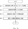
- FIG. 13 is a flow chart showing the operation of the control system 32 according to the fourth embodiment.
- the communication unit 4 receives an inquiry message including the device ID and the authority level assigned to the communication terminal 40 from the communication terminal 40 (S41).
- the selection unit 9 confirms the authority level included in the inquiry message of the communication terminal 40 (S42).
- the selection unit 9 refers to the storage unit 7 and selects information on the aircraft 2 corresponding to the authority level of the communication terminal 40 (S43).
- the communication unit 4 transmits the information selected by the selection unit 9 to the communication terminal 40 (S44).
- control system 32 provides information on the aircraft 2 according to the authority level of the communication terminal 40.
- the control system 32 can suppress leakage of information about the aircraft 2 and improve security.
- the control system 32 can appropriately provide information on the aircraft 2 according to the situation while improving security.
- FIG. 14 is a block diagram showing the configuration of an aircraft identification system 103 according to the fifth embodiment.
- An aircraft identification system 103 according to the fifth embodiment includes an aircraft 21 , a control system 33 and a communication terminal 40 .
- the aircraft 21 includes a communication section 14 , a storage section 18 and an encryption section 19 .
- the control system 33 includes a communication section 4 , a storage section 7 , a selection section 9 and an encryption section 10 .
- the same reference numerals are given to the same components as in the first to fourth embodiments, and detailed description thereof will be omitted as appropriate.
- the flying object 21 according to the fifth embodiment can encrypt and transmit the information it owns according to the authority level. Further, the flying object identification system 103 according to the fifth embodiment, like the flying object identification system 102 according to the fourth embodiment, sends appropriate information to the communication terminal 40 according to the authority level of the communication terminal 40. It is a system to disclose.
- the storage unit 18 of the flying object 21 stores the flying object information, which is information about the flying object 21, and the authority level in association with each other.
- the storage unit 18 stores a plurality of flying object information regarding the flying object 21 according to the authority level.
- the information of authority level 3 corresponds to the personal information of the user of the aircraft 21, and the information of authority level 2 corresponds to the information of the flight route and the remaining amount of the battery 17.
- FIG. The information of authority level 1 corresponds to the information of the destination of the aircraft 21 .
- the administrator or user of the flying object 21 may set the authority level associated with the flying object information of the flying object 21 . That is, the flying object 21 can set which information among the information to be transmitted is disclosed to which authority level. Also, the flying object 21 can set which information to transmit.
- the encryption unit 19 encrypts the aircraft information associated with the predetermined authority level. For example, when the predetermined authority level is 3, the encryption unit 19 encrypts the aircraft information associated with authority level 3. Further, when the predetermined authority level is 1-3, the encryption unit 19 may encrypt all the aircraft information associated with authority levels 1-3.
- the communication unit 14 transmits encrypted aircraft information.
- Aircraft information is aircraft information, for example, flight route, personal information of aircraft owner and aircraft manager, payload, aircraft information, connection information, aircraft status such as presence or absence of malfunction and remaining energy. , maintenance information, etc.
- the communication terminal 40 has an authority level according to the status of the user, and can decrypt the encrypted aircraft information received from the aircraft 21 .
- Users of the communication terminal 40 are, for example, the police, parking lot managers, and ordinary people.
- the police have a communication terminal 40 assigned authority level 3
- the parking lot manager has a communication terminal 40 assigned authority level 2
- the general public has a communication terminal 40 assigned authority level 1. holds 40.
- the encryption unit 19 encrypts the aircraft information of the aircraft 21 associated with the authority level 3 and the communication unit 14 transmits the encrypted aircraft information
- the authority level held by the police is 3 communication terminal 40 can decrypt the encrypted privilege level 3 aircraft information of the aircraft 21 .
- the communication terminal 40 of authority level 2 owned by the parking lot manager and the communication terminal 40 of authority level 1 owned by the general public cannot decrypt the encrypted aircraft information of authority level 3.
- the communication terminal 40 at authority level 3 can receive aircraft information associated with authority level 1 or 2.
- the communication terminal 40 with authority level 3 can decrypt the encrypted aircraft information with authority level 1 or 2 as well. That is, the communication terminal 40 can acquire the aircraft information associated with its own authority level and authority levels lower than its own authority level.
- the flying object 21 according to the fifth embodiment can encrypt and transmit the information it owns according to the authority level, thereby improving security and enabling communication with an appropriate authority level.
- Information can be communicated to the owner of the terminal 40 .
- the control system 33 according to the fifth embodiment can also disclose appropriate information to the communication terminal 40 in response to an inquiry from the communication terminal 40 according to the authority level of the communication terminal 40.
- an encryption unit 10 is added as compared with the control system 32 according to the fourth embodiment.
- the encryption unit 10 of the control system 33 encrypts the information of the aircraft 21 associated with the predetermined authority level. For example, when the predetermined authority level is 3, the encryption unit 10 encrypts the aircraft information of the aircraft 21 associated with the authority level 3. Note that the encryption unit 10 may encrypt all the aircraft information associated with the authority levels 1 to 3 when the predetermined authority levels are 1 to 3.
- FIG. The communication unit 4 transmits encrypted information on the flying object 21 .
- the communication terminal 40 with authority level 3 can acquire the information on the authority level 3 aircraft 21 by decrypting the encrypted information on the authority level 3 aircraft 21 .
- the operation of the control system 33 will be described below with reference to FIG. 15 .
- FIG. 15 is a flow chart showing the operation of the control system 33 according to the fifth embodiment.
- the communication unit 4 receives an inquiry message including the device ID and the authority level assigned to the communication terminal 40 from the communication terminal 40 (S51).
- the selection unit 9 confirms the authority level included in the inquiry message of the communication terminal 40 (S52).
- the selection unit 9 refers to the storage unit 7 and selects the information of the aircraft 21 corresponding to the authority level 3 (S53).
- the encryption unit 10 encrypts the information of the aircraft 21 associated with the authority level 3 (S54).
- the communication unit 4 transmits to the communication terminal 40 the information on the aircraft 21 associated with the authority level 3 selected by the selection unit 9 and encrypted by the encryption unit 10 (S55).
- control system 33 can prevent interception by other communication terminals 40 by providing the encryption unit 10 .
- the control system 33 can further suppress leakage of information on the aircraft 21 and improve the security of the communication system between the communication terminal 40 and the control system 33 .
- the control system 33 can appropriately provide information on the aircraft 21 according to the situation while improving security.
- the aircraft 2 and 21 in case of an emergency, directly send emergency information including malfunction and landing location to the communication terminal 40 without going through the control system 32 and control system 33. You may make it transmit.
- the aircraft 2 and 21 may broadcast emergency information to the communication terminals 40 on the ground located at the landing site and on the landing route.
- the landing route is a flight route from the occurrence of an emergency such as a malfunction of the aircraft 2 and 21 to the landing of the aircraft 2 and 21 at the landing point.
- the aircraft 2 and 21 may broadcast emergency information to the communication terminal 40 on the ground via a mobile network managed by a communication carrier without going through the control systems 32 and 33 .
- the flying object 2 and the flying object 21 can immediately transmit emergency information to the communication terminal 40, thereby suppressing damage caused by an accident. be able to.
- FIG. 16 shows control devices in aircraft 2, aircraft 20, aircraft 21, control system 3, control system 30, control system 31, control system 32, control system 33, and communication terminal 40 according to the respective embodiments. It is a block diagram showing a configuration example.
- these controllers include network interface 201 , processor 202 and memory 203 .
- the network interface 201 may be used to communicate with network nodes (e.g., eNB, MME, P-GW,).
- Network interface 201 may include, for example, an IEEE 802.3 series compliant network interface card (NIC).
- eNB stands for evolved Node B
- MME Mobility Management Entity
- P-GW Packet Data Network Gateway.
- IEEE stands for Institute of Electrical and Electronics Engineers.
- the processor 202 reads out software (computer program) from the memory 203 and executes it to operate the aircraft 2, 20, 21, control system 3, control system 30, and control system described in the above-described embodiments. 31 , control system 32 , control system 33 , and communication terminal 40 .
- Processor 202 may be, for example, a microprocessor, MPU, or CPU. Processor 202 may include multiple processors.
- the memory 203 is configured by a combination of volatile memory and nonvolatile memory.
- Memory 203 may include storage remotely located from processor 202 .
- the processor 202 may access the memory 203 via an I/O (Input/Output) interface (not shown).
- I/O Input/Output
- the memory 203 is used to store software modules.
- the processor 202 reads and executes these software module groups from the memory 203 to operate the aircraft 2, 20, 21, control system 3, control system 30, and control system described in the above-described embodiments. 31, the control system 32, the control system 33, and the communication terminal 40 can perform operations and processes.
- control system 3 As described with reference to FIG. 16, the aircraft 2, 20, 21, control system 3, control system 30, control system 31, control system 32, control system 33, and communication terminal 40 in the above embodiment
- Each of the processors of the control device executes one or more programs containing instruction groups for causing the computer to perform the operations and processes described in the above embodiments.
- Non-transitory computer readable media include various types of tangible storage media.
- Examples of non-transitory computer readable media include magnetic recording media (eg, floppy disks, magnetic tapes, hard disk drives), magneto-optical recording media (eg, magneto-optical discs), CD-ROMs, CD-Rs, CD-R/Ws , semiconductor memory (eg, mask ROM, PROM (Programmable ROM), EPROM (Erasable PROM), flash ROM, RAM).
- the program may also be delivered to the computer on various types of transitory computer readable medium. Examples of transitory computer-readable media include electrical signals, optical signals, and electromagnetic waves. Transitory computer-readable media can deliver the program to the computer via wired channels, such as wires and optical fibers, or wireless channels.
- (Appendix 1) a communication unit that receives from the communication terminal an image including the flying object captured by the communication terminal and position information of the communication terminal; an estimation unit that estimates an estimated position of the flying object using the background information and the position information included in the image; an identification unit that identifies the flying object using the estimated position of the flying object; wherein the communication unit transmits information of the identified flying object to the communication terminal; control system.
- the communication unit transmits a request signal requesting an aircraft ID to the aircraft using radio waves having directivity to the estimated position, When the communication unit acquires a response signal to the request signal, the identification unit identifies the aircraft using the aircraft ID included in the response signal.
- the control system according to Appendix 1. (Appendix 3) further comprising a storage unit that stores information about the flying object; The communication unit refers to the storage unit and transmits information about the flying object identified by the identification unit to the communication terminal.
- the identifying unit determines that the flying object at the estimated position is a suspicious flying object when the communication unit fails to acquire the body ID of the flying object, The communication unit transmits a determination result to the communication terminal, The control system according to Appendix 2. (Appendix 5) If the aircraft ID is not included in the response signal, or if the aircraft ID included in the response signal is not associated with the aircraft, the identification unit identifies the aircraft at the estimated position. The control system according to appendix 4, which determines that the aircraft is a suspicious flying object.
- (Appendix 8) a device ID control unit that holds the device ID of its own device; A communication unit that transmits the machine ID, When receiving a request signal for the device ID, the communication unit transmits a response signal including the device ID in response to the request. Airplane.
- Reference Signs List 1 100, 101, 102, 103 aircraft identification system 2, 20, 21 aircraft 3, 30, 31, 32, 33 control system 4 communication unit 5 identification unit 6 generation unit 7 storage unit 8 estimation unit 9 selection unit 10
Abstract
Description
通信端末において撮影された飛行体を含む画像と、前記通信端末の位置情報とを前記通信端末から受信する通信部と、
前記画像に含まれる背景情報及び前記位置情報を用いて、前記飛行体の推定位置を推定する推定部と、
前記飛行体の推定位置を用いて、前記飛行体を識別する識別部と、を備え、
前記通信部は、識別された前記飛行体の情報を前記通信端末へ送信する。 The control system according to the present disclosure is
a communication unit that receives from the communication terminal an image including the flying object captured by the communication terminal and position information of the communication terminal;
an estimation unit that estimates an estimated position of the flying object using the background information and the position information included in the image;
an identification unit that identifies the flying object using the estimated position of the flying object;
The communication unit transmits information on the identified flying object to the communication terminal.
通信端末において撮影された飛行体を含む画像と、前記通信端末の位置情報とを前記通信端末から受信し、
前記画像に含まれる背景情報及び前記位置情報を用いて、前記飛行体の推定位置を推定し、
前記飛行体の推定位置を用いて、前記飛行体を識別し、
識別された前記飛行体の情報を前記通信端末へ送信する方法である。 The flying object identification method according to the present disclosure includes:
receiving from the communication terminal an image including the aircraft captured by the communication terminal and position information of the communication terminal;
estimating an estimated position of the flying object using the background information and the position information contained in the image;
identifying the aircraft using the estimated position of the aircraft;
A method of transmitting information on the identified flying object to the communication terminal.
通信端末において撮影された飛行体を含む画像と、前記通信端末の位置情報とを前記通信端末から受信し、
前記画像に含まれる背景情報及び前記位置情報を用いて、前記飛行体の推定位置を推定し、
前記飛行体の推定位置を用いて、前記飛行体を識別し、
識別された前記飛行体の情報を前記通信端末へ送信する、
処理をコンピュータに実行させるためのプログラムが格納された一時的なコンピュータ可読媒体である。 A computer-readable medium according to the present disclosure comprises:
receiving from the communication terminal an image including the aircraft captured by the communication terminal and position information of the communication terminal;
estimating an estimated position of the flying object using the background information and the position information contained in the image;
identifying the aircraft using the estimated position of the aircraft;
transmitting information of the identified flying object to the communication terminal;
A temporary computer-readable medium storing a program for causing a computer to execute a process.
自機の機体IDを保持する機体ID制御部と、
前記機体IDを発信する通信部とを備え、
前記通信部は、前記機体IDの要求信号を受信したとき、要求に応じて、前記機体IDを含む応答信号を発信する。 The aircraft according to the present disclosure is
a device ID control unit that holds the device ID of its own device;
A communication unit that transmits the machine ID,
When receiving the request signal for the device ID, the communication unit transmits a response signal including the device ID in response to the request.
図1は、第1の実施形態にかかる飛行体識別システム1の構成を示すブロック図である。飛行体識別システム1は、飛行体2、管制システム3を備える。 (First embodiment)
FIG. 1 is a block diagram showing the configuration of an
例えば、機体ID制御部15は、所定の変更パターンとして、図2の機体IDテーブルに記載しているように、予め複数の機体IDを作成しておき、機体IDを所定の時間ごとに変更してもよい。通信部14は、機体ID制御部15が記憶している機体IDテーブルを管制システム3に送信してもよい。これにより、機体ID制御部15は、自機の飛行を管制する管制システム3との間で機体IDの変更パターンを共有することができる。もしくは、通信部14は、管制システム3から機体IDテーブルを受信してもよい。これらにより、飛行体2と管制システム3とにおいて、飛行体2の機体IDの変更パターンが共有される。 The device
For example, as a predetermined change pattern, the device
はじめに、通信部4は、飛行体2の第1の機体ID及び位置情報を取得する(S1)。ここでは、機体IDを区別するため、最初の機体IDを第1の機体ID、変更後の機体IDを第2の機体IDと呼ぶ。次に、識別部5は、第1の機体IDを用いて飛行体2を識別する(S2)。以降、管制システム3は、第1の機体IDを発信する飛行体2と通信し、飛行体2の運航管理及び航空管制を行う。 The operation of the
First, the
図4は、第2の実施形態にかかる飛行体識別システム100の構成を示したブロック図である。飛行体識別システム100は、飛行体20、管制システム30を備える。 (Second embodiment)
FIG. 4 is a block diagram showing the configuration of an
飛行体20は、上述の構成要素を備えることで、管制システム30と通信しながら飛行することができる。 The
The flying
識別部5は、推定位置と第2の機体IDを取得した際の位置との差が閾値以下のとき(S25、YES)、記憶部7が記憶する機体IDの変更パターンを参照する。識別部5は、第2の機体IDが、第1の機体IDを発信していた飛行体20の機体IDの変更パターンによって特定される機体IDと同じであるかを判定する(S26)。識別部5は、第2の機体IDが変更パターンによって特定される機体IDと異なる場合(S26、NO)、第2の機体IDを発信している飛行体20が第1の機体IDを発信した飛行体20とは異なる飛行体20として識別する(S28)。識別部5は、第2の機体IDが変更パターンによって特定される機体IDと同じ場合(S26、YES)、第2の機体IDを発信している飛行体20と、第1の機体IDを発信していた飛行体20とが同一の飛行体20であると判定する(S27)。また、図8においては、ステップS25及びS26の順に処理が実行されることが示されているが、ステップS25及びS26の順番は、変更されてもよい。例えば、管制システム30は、ステップS26の処理を実行してから、ステップS25の処理を実行してもよい。 On the other hand, when the
When the difference between the estimated position and the position when the second machine ID is obtained is equal to or less than the threshold (S25, YES), the
図9を用いて、第3の実施形態にかかる飛行体識別システム101について説明する。第3の実施形態にかかる飛行体識別システム101は、飛行体2、管制システム31、通信端末40を備える。飛行体2は、通信部14、機体ID制御部15を備える。管制システム31は、通信部4、識別部5、推定部8を備える。第3の実施形態にかかる飛行体識別システム101は、通信端末40を用いて飛行体2を識別するシステムである。第3の実施形態にかかる飛行体識別システム101において、第1及び第2の実施形態と同様の構成要素には同様の符号を付し、適宜詳細な説明を省略する。 (Third embodiment)
An
通信端末40は、飛行体2に対して、機体ID要求に加えて、メッセージを伝えるようにしてもよい。メッセージは、例えば、飛行中の騒音が大きくうるさいといった内容や滞在目的等であってよい。通信端末40は、飛行体2から応答があったとき、飛行体2の滞在目的などの事情を取得することができる。一方、通信端末40は、飛行体2から応答を得ることができない場合、飛行体2を不審な機体として判定し、通信端末40の位置周辺に不審な機体が飛行及び滞在していることを警察に通報するようにしてもよい。 Further, the
The
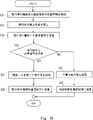
はじめに、通信部4は、通信端末40において撮影された飛行体2を含む画像と、通信端末40の位置情報とを通信端末40から受信する(S31)。推定部8は、受信した画像に含まれる背景情報及び位置情報を用いて、飛行体2の推定位置を推定する(S32)。通信部4は、推定部8が推定した飛行体2の推定位置に、指向性のある電波を用いて機体IDを要求する要求信号を飛行体2に送信する(S33)。通信部4が要求信号に対する応答信号を受信したとき(S34、YES)、識別部5は、応答信号に含まれる機体IDを用いて飛行体2を識別する(S35)。通信部4は、識別された飛行体2の情報を通信端末40に送信する(S36)一方で、通信部4が要求信号に対する応答信号を受信できなかったとき(S34、NO)、識別部5は、推定位置の飛行体2を不審な飛行体2であると判定する(S37)。通信部4は、判定結果を通信端末40に送信する(S38)。また、識別部5は、ステップS34において受信した応答信号に含まれる機体IDに対応付けられた飛行体が存在しないと判定した場合、推定位置の飛行体2を不審な飛行体2であると判定してもよい。また、識別部5は、ステップS34において受信した応答信号に機体IDが含まれていない場合、推定位置の飛行体2を不審な飛行体2であると判定してもよい。 FIG. 10 is a flow chart showing the operation of the
First, the
図11は、第4の実施形態にかかる飛行体識別システム102の構成を示したブロック図である。第4の実施形態にかかる飛行体識別システム102は、飛行体2、管制システム32、通信端末40を備える。飛行体2は、通信部14、機体ID制御部15を備える。管制システム32は、通信部4、記憶部7、選択部9を備える。第4の実施形態にかかる飛行体識別システム102は、通信端末40の権限レベルに応じて、通信端末40に適切な情報を開示するシステムである。第4の実施形態にかかる飛行体識別システム102において、第1~第3の実施形態と同様の構成要素には同様の符号を付し、適宜詳細な説明を省略する。 (Fourth embodiment)
FIG. 11 is a block diagram showing the configuration of an
選択部9は、通信端末40に割り当てられた権限レベルより高い権限レベルの情報の問い合わせに対しては、飛行体2の情報を選択しない。この場合、通信部4は、飛行体2の情報を提供できないことを通信端末40に通知するようにしてもよい。
これにより、選択部9は、通信端末40の権限レベルに応じて、通信端末40に送信すべき情報を選択することができる。 Alternatively, the
The
Thereby, the
通信部4は、通信端末40から機体ID及び通信端末40に割り当てられた権限レベルを含む問い合わせメッセージを受信する(S41)。選択部9は、通信端末40の問い合わせメッセージに含まれる権限レベルを確認する(S42)。選択部9は、記憶部7を参照し、通信端末40の権限レベルに対応する飛行体2の情報を選択する(S43)。通信部4は、通信端末40に選択部9で選択した情報を送信する(S44)。 FIG. 13 is a flow chart showing the operation of the
The
図14は、第5の実施形態にかかる飛行体識別システム103の構成を示すブロック図である。第5の実施形態にかかる飛行体識別システム103は、飛行体21、管制システム33、通信端末40を備える。飛行体21は、通信部14、記憶部18、暗号化部19を備える。管制システム33は、通信部4、記憶部7、選択部9、暗号化部10を備える。第5の実施形態にかかる飛行体識別システム103において、第1~第4の実施形態と同様の構成要素には同様の符号を付し、適宜詳細な説明を省略する。第5の実施形態にかかる飛行体21は、自身の保有する情報を権限レベルに応じて暗号化して発信することが可能である。また、第5の実施形態にかかる飛行体識別システム103は、第4の実施形態にかかる飛行体識別システム102と同様に、通信端末40の権限レベルに応じて、通信端末40に適切な情報を開示するシステムである。 (Fifth embodiment)
FIG. 14 is a block diagram showing the configuration of an
例えば、暗号化部19が権限レベル3に対応付けられた飛行体21の飛行体情報を暗号化し、通信部14が暗号化された飛行体情報を発信しているとき、警察が保有する権限レベル3の通信端末40は、飛行体21の暗号化された権限レベル3の飛行体情報を復号化することができる。この場合、駐機場管理者が保有する権限レベル2の通信端末40や一般人が保有する権限レベル1の通信端末40では、暗号化された権限レベル3の飛行体情報を復号化することができない。また、権限レベル3の通信端末40は、権限レベル1または2に対応付けられた飛行体情報を受信することができる。また、権限レベル3の通信端末40は、暗号化された権限レベル1または2の飛行体情報も復号化することができる。すなわち、通信端末40は、自身の権限レベル及び自身の権限レベルよりも低い権限レベルに対応付けられた飛行体情報を取得することができる。 The
For example, when the
(付記1)
通信端末において撮影された飛行体を含む画像と、前記通信端末の位置情報とを前記通信端末から受信する通信部と、
前記画像に含まれる背景情報及び前記位置情報を用いて、前記飛行体の推定位置を推定する推定部と、
前記飛行体の推定位置を用いて、前記飛行体を識別する識別部と、を備え、
前記通信部は、識別された前記飛行体の情報を前記通信端末へ送信する、
管制システム。
(付記2)
前記通信部は、前記推定位置に指向性のある電波を用いて機体IDを要求する要求信号を前記飛行体へ送信し、
前記識別部は、前記通信部において前記要求信号に対する応答信号が取得された場合に、前記応答信号に含まれる前記機体IDを用いて前記飛行体を識別する、
付記1に記載の管制システム。
(付記3)
前記飛行体に関する情報を記憶する記憶部をさらに備え、
前記通信部は、前記記憶部を参照し、前記識別部が識別した前記飛行体に関する情報を前記通信端末に送信する、
付記1または2に記載の管制システム。
(付記4)
前記識別部は、前記通信部が前記飛行体の前記機体IDを取得できなかった場合、前記推定位置の前記飛行体を不審な飛行体であると判定し、
前記通信部は、前記通信端末に判定結果を送信する、
付記2に記載の管制システム。
(付記5)
前記識別部は、前記応答信号に前記機体IDが含まれていなかった場合、もしくは、前記応答信号に含まれる機体IDに前記飛行体が対応付けられていない場合、前記推定位置の前記飛行体を不審な飛行体であると判定する、付記4に記載の管制システム。
(付記6)
通信端末において撮影された飛行体を含む画像と、前記通信端末の位置情報とを前記通信端末から受信し、
前記画像に含まれる背景情報及び前記位置情報を用いて、前記飛行体の推定位置を推定し、
前記飛行体の推定位置を用いて、前記飛行体を識別し、
識別された前記飛行体の情報を前記通信端末へ送信する、
飛行体識別方法。
(付記7)
通信端末において撮影された飛行体を含む画像と、前記通信端末の位置情報とを前記通信端末から受信し、
前記画像に含まれる背景情報及び前記位置情報を用いて、前記飛行体の推定位置を推定し、
前記飛行体の推定位置を用いて、前記飛行体を識別し、
識別された前記飛行体の情報を前記通信端末へ送信する、
処理をコンピュータに実行させるためのプログラムが格納された一時的なコンピュータ可読媒体。
(付記8)
自機の機体IDを保持する機体ID制御部と、
前記機体IDを発信する通信部とを備え、
前記通信部は、前記機体IDの要求信号を受信したとき、要求に応じて、前記機体IDを含む応答信号を発信する、
飛行体。 Some or all of the above-described embodiments can also be described in the following supplementary remarks, but are not limited to the following.
(Appendix 1)
a communication unit that receives from the communication terminal an image including the flying object captured by the communication terminal and position information of the communication terminal;
an estimation unit that estimates an estimated position of the flying object using the background information and the position information included in the image;
an identification unit that identifies the flying object using the estimated position of the flying object;
wherein the communication unit transmits information of the identified flying object to the communication terminal;
control system.
(Appendix 2)
The communication unit transmits a request signal requesting an aircraft ID to the aircraft using radio waves having directivity to the estimated position,
When the communication unit acquires a response signal to the request signal, the identification unit identifies the aircraft using the aircraft ID included in the response signal.
The control system according to
(Appendix 3)
further comprising a storage unit that stores information about the flying object;
The communication unit refers to the storage unit and transmits information about the flying object identified by the identification unit to the communication terminal.
The control system according to
(Appendix 4)
The identifying unit determines that the flying object at the estimated position is a suspicious flying object when the communication unit fails to acquire the body ID of the flying object,
The communication unit transmits a determination result to the communication terminal,
The control system according to
(Appendix 5)
If the aircraft ID is not included in the response signal, or if the aircraft ID included in the response signal is not associated with the aircraft, the identification unit identifies the aircraft at the estimated position. The control system according to
(Appendix 6)
receiving from the communication terminal an image including the aircraft captured by the communication terminal and position information of the communication terminal;
estimating an estimated position of the flying object using the background information and the position information contained in the image;
identifying the aircraft using the estimated position of the aircraft;
transmitting information of the identified flying object to the communication terminal;
Aircraft identification method.
(Appendix 7)
receiving from the communication terminal an image including the aircraft captured by the communication terminal and position information of the communication terminal;
estimating an estimated position of the flying object using the background information and the position information contained in the image;
identifying the aircraft using the estimated position of the aircraft;
transmitting information of the identified flying object to the communication terminal;
A temporary computer-readable medium that stores a program for causing a computer to execute a process.
(Appendix 8)
a device ID control unit that holds the device ID of its own device;
A communication unit that transmits the machine ID,
When receiving a request signal for the device ID, the communication unit transmits a response signal including the device ID in response to the request.
Airplane.
2、20、21 飛行体
3、30、31、32、33 管制システム
4 通信部
5 識別部
6 生成部
7 記憶部
8 推定部
9 選択部
10 暗号化部
11 飛行制御部
12 駆動機構
13 センサ
14 通信部
15 機体ID制御部
16 表示部
17 バッテリ
18 記憶部
19 暗号化部
40 通信端末
201 ネットワークインタフェース
202 プロセッサ
203 メモリ
Claims (8)
- 通信端末において撮影された飛行体を含む画像と、前記通信端末の位置情報とを前記通信端末から受信する通信部と、
前記画像に含まれる背景情報及び前記位置情報を用いて、前記飛行体の推定位置を推定する推定部と、
前記飛行体の推定位置を用いて、前記飛行体を識別する識別部と、を備え、
前記通信部は、識別された前記飛行体の情報を前記通信端末へ送信する、
管制システム。 a communication unit that receives from the communication terminal an image including the flying object captured by the communication terminal and position information of the communication terminal;
an estimation unit that estimates an estimated position of the flying object using the background information and the position information included in the image;
an identification unit that identifies the flying object using the estimated position of the flying object;
wherein the communication unit transmits information of the identified flying object to the communication terminal;
control system. - 前記通信部は、前記推定位置に指向性のある電波を用いて機体IDを要求する要求信号を前記飛行体へ送信し、
前記識別部は、前記通信部において前記要求信号に対する応答信号が取得された場合に、前記応答信号に含まれる前記機体IDを用いて前記飛行体を識別する、
請求項1に記載の管制システム。 The communication unit transmits a request signal requesting an aircraft ID to the aircraft using radio waves having directivity to the estimated position,
When the communication unit acquires a response signal to the request signal, the identification unit identifies the aircraft using the aircraft ID included in the response signal.
The control system according to claim 1. - 前記飛行体に関する情報を記憶する記憶部をさらに備え、
前記通信部は、前記記憶部を参照し、前記識別部が識別した前記飛行体に関する情報を前記通信端末に送信する、
請求項1または2に記載の管制システム。 further comprising a storage unit that stores information about the flying object;
The communication unit refers to the storage unit and transmits information about the flying object identified by the identification unit to the communication terminal.
The control system according to claim 1 or 2. - 前記識別部は、前記通信部が前記飛行体の前記機体IDを取得できなかった場合、前記推定位置の前記飛行体を不審な飛行体であると判定し、
前記通信部は、前記通信端末に判定結果を送信する、
請求項2に記載の管制システム。 The identifying unit determines that the flying object at the estimated position is a suspicious flying object when the communication unit fails to acquire the body ID of the flying object,
The communication unit transmits a determination result to the communication terminal,
The control system according to claim 2. - 前記識別部は、前記応答信号に前記機体IDが含まれていなかった場合、もしくは、前記応答信号に含まれる機体IDに前記飛行体が対応付けられていない場合、前記推定位置の前記飛行体を不審な飛行体であると判定する、請求項4に記載の管制システム。 If the aircraft ID is not included in the response signal, or if the aircraft ID included in the response signal is not associated with the aircraft, the identification unit identifies the aircraft at the estimated position. 5. The control system according to claim 4, which determines that it is a suspicious flying object.
- 通信端末において撮影された飛行体を含む画像と、前記通信端末の位置情報とを前記通信端末から受信し、
前記画像に含まれる背景情報及び前記位置情報を用いて、前記飛行体の推定位置を推定し、
前記飛行体の推定位置を用いて、前記飛行体を識別し、
識別された前記飛行体の情報を前記通信端末へ送信する、
飛行体識別方法。 receiving from the communication terminal an image including the aircraft captured by the communication terminal and position information of the communication terminal;
estimating an estimated position of the flying object using the background information and the position information contained in the image;
identifying the aircraft using the estimated position of the aircraft;
transmitting information of the identified flying object to the communication terminal;
Aircraft identification method. - 通信端末において撮影された飛行体を含む画像と、前記通信端末の位置情報とを前記通信端末から受信し、
前記画像に含まれる背景情報及び前記位置情報を用いて、前記飛行体の推定位置を推定し、
前記飛行体の推定位置を用いて、前記飛行体を識別し、
識別された前記飛行体の情報を前記通信端末へ送信する、
処理をコンピュータに実行させるためのプログラムが格納された一時的なコンピュータ可読媒体。 receiving from the communication terminal an image including the aircraft captured by the communication terminal and position information of the communication terminal;
estimating an estimated position of the flying object using the background information and the position information contained in the image;
identifying the aircraft using the estimated position of the aircraft;
transmitting information of the identified flying object to the communication terminal;
A temporary computer-readable medium that stores a program for causing a computer to execute a process. - 自機の機体IDを保持する機体ID制御部と、
前記機体IDを発信する通信部とを備え、
前記通信部は、前記機体IDの要求信号を受信したとき、要求に応じて、前記機体IDを含む応答信号を発信する、
飛行体。 a device ID control unit that holds the device ID of its own device;
A communication unit that transmits the machine ID,
When the communication unit receives a request signal for the machine ID, it transmits a response signal including the machine ID in response to the request.
Airplane.
Priority Applications (5)
| Application Number | Priority Date | Filing Date | Title |
|---|---|---|---|
| PCT/JP2021/003125 WO2022162848A1 (en) | 2021-01-29 | 2021-01-29 | Control system, flying body identification method, computer-readable medium, and flying body |
| CN202180092200.2A CN116888653A (en) | 2021-01-29 | 2021-01-29 | Air traffic control system, method of identifying flying object, computer readable medium and flying object |
| US18/273,697 US20240078920A1 (en) | 2021-01-29 | 2021-01-29 | Air traffic control system, method of identifying flying object, computer readable medium, and flying object |
| JP2022577928A JPWO2022162848A5 (en) | 2021-01-29 | Control system, aircraft identification method, program and aircraft | |
| EP21922864.0A EP4287162A1 (en) | 2021-01-29 | 2021-01-29 | Control system, flying body identification method, computer-readable medium, and flying body |
Applications Claiming Priority (1)
| Application Number | Priority Date | Filing Date | Title |
|---|---|---|---|
| PCT/JP2021/003125 WO2022162848A1 (en) | 2021-01-29 | 2021-01-29 | Control system, flying body identification method, computer-readable medium, and flying body |
Publications (1)
| Publication Number | Publication Date |
|---|---|
| WO2022162848A1 true WO2022162848A1 (en) | 2022-08-04 |
Family
ID=82652754
Family Applications (1)
| Application Number | Title | Priority Date | Filing Date |
|---|---|---|---|
| PCT/JP2021/003125 WO2022162848A1 (en) | 2021-01-29 | 2021-01-29 | Control system, flying body identification method, computer-readable medium, and flying body |
Country Status (4)
| Country | Link |
|---|---|
| US (1) | US20240078920A1 (en) |
| EP (1) | EP4287162A1 (en) |
| CN (1) | CN116888653A (en) |
| WO (1) | WO2022162848A1 (en) |
Citations (7)
| Publication number | Priority date | Publication date | Assignee | Title |
|---|---|---|---|---|
| JP2003057065A (en) * | 2001-08-15 | 2003-02-26 | Koji Onuma | Method for flight vehicle to verify location of other flight vehicle |
| JP2014220604A (en) * | 2013-05-07 | 2014-11-20 | 三菱電機株式会社 | Photographing position information display device |
| JP2017151839A (en) | 2016-02-26 | 2017-08-31 | 三菱重工業株式会社 | Flight vehicle operating system and flight vehicle operating method |
| JP2017220814A (en) * | 2016-06-08 | 2017-12-14 | シャープ株式会社 | Image processing apparatus, image processing system, image processing method, and program |
| JP2018124067A (en) * | 2017-01-30 | 2018-08-09 | 日本電信電話株式会社 | Azimuth estimating device, photographing/map display device, method, and program |
| JP2019144804A (en) * | 2018-02-20 | 2019-08-29 | ソフトバンク株式会社 | Image processing apparatus, flying body, and program |
| US20200284607A1 (en) * | 2019-03-08 | 2020-09-10 | Aptiv Technologies Limited | Object location indicator system and method |
-
2021
- 2021-01-29 EP EP21922864.0A patent/EP4287162A1/en active Pending
- 2021-01-29 CN CN202180092200.2A patent/CN116888653A/en active Pending
- 2021-01-29 US US18/273,697 patent/US20240078920A1/en active Pending
- 2021-01-29 WO PCT/JP2021/003125 patent/WO2022162848A1/en active Application Filing
Patent Citations (7)
| Publication number | Priority date | Publication date | Assignee | Title |
|---|---|---|---|---|
| JP2003057065A (en) * | 2001-08-15 | 2003-02-26 | Koji Onuma | Method for flight vehicle to verify location of other flight vehicle |
| JP2014220604A (en) * | 2013-05-07 | 2014-11-20 | 三菱電機株式会社 | Photographing position information display device |
| JP2017151839A (en) | 2016-02-26 | 2017-08-31 | 三菱重工業株式会社 | Flight vehicle operating system and flight vehicle operating method |
| JP2017220814A (en) * | 2016-06-08 | 2017-12-14 | シャープ株式会社 | Image processing apparatus, image processing system, image processing method, and program |
| JP2018124067A (en) * | 2017-01-30 | 2018-08-09 | 日本電信電話株式会社 | Azimuth estimating device, photographing/map display device, method, and program |
| JP2019144804A (en) * | 2018-02-20 | 2019-08-29 | ソフトバンク株式会社 | Image processing apparatus, flying body, and program |
| US20200284607A1 (en) * | 2019-03-08 | 2020-09-10 | Aptiv Technologies Limited | Object location indicator system and method |
Also Published As
| Publication number | Publication date |
|---|---|
| CN116888653A (en) | 2023-10-13 |
| US20240078920A1 (en) | 2024-03-07 |
| JPWO2022162848A1 (en) | 2022-08-04 |
| EP4287162A1 (en) | 2023-12-06 |
Similar Documents
| Publication | Publication Date | Title |
|---|---|---|
| US11693402B2 (en) | Flight management system for UAVs | |
| US11316581B2 (en) | Network capacity management | |
| US11230377B2 (en) | Unmanned aerial vehicle platform | |
| CA2984021C (en) | Systems and methods for remote distributed control of unmanned aircraft | |
| CN110199566B (en) | Unmanned aerial vehicle user equipment indication | |
| US20220185487A1 (en) | Circuit, base station, method, and recording medium | |
| WO2021173450A1 (en) | Uav systems, including autonomous uav operational containment systems, and associated systems, devices, and methods | |
| US20210264799A1 (en) | Uavs, including multi-processor uavs with secured parameters, and associated systems, devices, and methods | |
| JPWO2020095430A1 (en) | Unmanned aerial vehicle operation management device, takeoff and landing facility management device, unmanned aerial vehicle operation management method, and unmanned aerial vehicle system | |
| WO2022162848A1 (en) | Control system, flying body identification method, computer-readable medium, and flying body | |
| WO2022162850A1 (en) | Aircraft, control system, aircraft identification method, and computer-readable medium | |
| WO2022162849A1 (en) | Flight vehicle identification system, control system, flight vehicle identification method, computer-readable medium, and flight vehicle |
Legal Events
| Date | Code | Title | Description |
|---|---|---|---|
| 121 | Ep: the epo has been informed by wipo that ep was designated in this application |
Ref document number: 21922864 Country of ref document: EP Kind code of ref document: A1 |
|
| ENP | Entry into the national phase |
Ref document number: 2022577928 Country of ref document: JP Kind code of ref document: A |
|
| WWE | Wipo information: entry into national phase |
Ref document number: 18273697 Country of ref document: US |
|
| WWE | Wipo information: entry into national phase |
Ref document number: 202180092200.2 Country of ref document: CN |
|
| WWE | Wipo information: entry into national phase |
Ref document number: 2021922864 Country of ref document: EP |
|
| NENP | Non-entry into the national phase |
Ref country code: DE |
|
| ENP | Entry into the national phase |
Ref document number: 2021922864 Country of ref document: EP Effective date: 20230829 |