WO2022158293A1 - 配線モジュール - Google Patents
配線モジュール Download PDFInfo
- Publication number
- WO2022158293A1 WO2022158293A1 PCT/JP2022/000173 JP2022000173W WO2022158293A1 WO 2022158293 A1 WO2022158293 A1 WO 2022158293A1 JP 2022000173 W JP2022000173 W JP 2022000173W WO 2022158293 A1 WO2022158293 A1 WO 2022158293A1
- Authority
- WO
- WIPO (PCT)
- Prior art keywords
- circuit board
- wiring
- busbar
- cover
- connection piece
- Prior art date
- Legal status (The legal status is an assumption and is not a legal conclusion. Google has not performed a legal analysis and makes no representation as to the accuracy of the status listed.)
- Ceased
Links
Images


Classifications
-
- H—ELECTRICITY
- H01—ELECTRIC ELEMENTS
- H01M—PROCESSES OR MEANS, e.g. BATTERIES, FOR THE DIRECT CONVERSION OF CHEMICAL ENERGY INTO ELECTRICAL ENERGY
- H01M50/00—Constructional details or processes of manufacture of the non-active parts of electrochemical cells other than fuel cells, e.g. hybrid cells
- H01M50/20—Mountings; Secondary casings or frames; Racks, modules or packs; Suspension devices; Shock absorbers; Transport or carrying devices; Holders
- H01M50/298—Mountings; Secondary casings or frames; Racks, modules or packs; Suspension devices; Shock absorbers; Transport or carrying devices; Holders characterised by the wiring of battery packs
-
- B—PERFORMING OPERATIONS; TRANSPORTING
- B60—VEHICLES IN GENERAL
- B60R—VEHICLES, VEHICLE FITTINGS, OR VEHICLE PARTS, NOT OTHERWISE PROVIDED FOR
- B60R16/00—Electric or fluid circuits specially adapted for vehicles and not otherwise provided for; Arrangement of elements of electric or fluid circuits specially adapted for vehicles and not otherwise provided for
- B60R16/02—Electric or fluid circuits specially adapted for vehicles and not otherwise provided for; Arrangement of elements of electric or fluid circuits specially adapted for vehicles and not otherwise provided for electric constitutive elements
- B60R16/0207—Wire harnesses
- B60R16/0215—Protecting, fastening and routing means therefor
-
- H—ELECTRICITY
- H01—ELECTRIC ELEMENTS
- H01M—PROCESSES OR MEANS, e.g. BATTERIES, FOR THE DIRECT CONVERSION OF CHEMICAL ENERGY INTO ELECTRICAL ENERGY
- H01M50/00—Constructional details or processes of manufacture of the non-active parts of electrochemical cells other than fuel cells, e.g. hybrid cells
- H01M50/20—Mountings; Secondary casings or frames; Racks, modules or packs; Suspension devices; Shock absorbers; Transport or carrying devices; Holders
- H01M50/204—Racks, modules or packs for multiple batteries or multiple cells
- H01M50/207—Racks, modules or packs for multiple batteries or multiple cells characterised by their shape
- H01M50/209—Racks, modules or packs for multiple batteries or multiple cells characterised by their shape adapted for prismatic or rectangular cells
-
- H—ELECTRICITY
- H01—ELECTRIC ELEMENTS
- H01M—PROCESSES OR MEANS, e.g. BATTERIES, FOR THE DIRECT CONVERSION OF CHEMICAL ENERGY INTO ELECTRICAL ENERGY
- H01M50/00—Constructional details or processes of manufacture of the non-active parts of electrochemical cells other than fuel cells, e.g. hybrid cells
- H01M50/20—Mountings; Secondary casings or frames; Racks, modules or packs; Suspension devices; Shock absorbers; Transport or carrying devices; Holders
- H01M50/271—Lids or covers for the racks or secondary casings
-
- H—ELECTRICITY
- H01—ELECTRIC ELEMENTS
- H01M—PROCESSES OR MEANS, e.g. BATTERIES, FOR THE DIRECT CONVERSION OF CHEMICAL ENERGY INTO ELECTRICAL ENERGY
- H01M50/00—Constructional details or processes of manufacture of the non-active parts of electrochemical cells other than fuel cells, e.g. hybrid cells
- H01M50/20—Mountings; Secondary casings or frames; Racks, modules or packs; Suspension devices; Shock absorbers; Transport or carrying devices; Holders
- H01M50/284—Mountings; Secondary casings or frames; Racks, modules or packs; Suspension devices; Shock absorbers; Transport or carrying devices; Holders with incorporated circuit boards, e.g. printed circuit boards [PCB]
-
- H—ELECTRICITY
- H01—ELECTRIC ELEMENTS
- H01M—PROCESSES OR MEANS, e.g. BATTERIES, FOR THE DIRECT CONVERSION OF CHEMICAL ENERGY INTO ELECTRICAL ENERGY
- H01M50/00—Constructional details or processes of manufacture of the non-active parts of electrochemical cells other than fuel cells, e.g. hybrid cells
- H01M50/50—Current conducting connections for cells or batteries
- H01M50/502—Interconnectors for connecting terminals of adjacent batteries; Interconnectors for connecting cells outside a battery casing
- H01M50/503—Interconnectors for connecting terminals of adjacent batteries; Interconnectors for connecting cells outside a battery casing characterised by the shape of the interconnectors
-
- H—ELECTRICITY
- H01—ELECTRIC ELEMENTS
- H01M—PROCESSES OR MEANS, e.g. BATTERIES, FOR THE DIRECT CONVERSION OF CHEMICAL ENERGY INTO ELECTRICAL ENERGY
- H01M50/00—Constructional details or processes of manufacture of the non-active parts of electrochemical cells other than fuel cells, e.g. hybrid cells
- H01M50/50—Current conducting connections for cells or batteries
- H01M50/502—Interconnectors for connecting terminals of adjacent batteries; Interconnectors for connecting cells outside a battery casing
- H01M50/507—Interconnectors for connecting terminals of adjacent batteries; Interconnectors for connecting cells outside a battery casing comprising an arrangement of two or more busbars within a container structure, e.g. busbar modules
-
- H—ELECTRICITY
- H01—ELECTRIC ELEMENTS
- H01M—PROCESSES OR MEANS, e.g. BATTERIES, FOR THE DIRECT CONVERSION OF CHEMICAL ENERGY INTO ELECTRICAL ENERGY
- H01M50/00—Constructional details or processes of manufacture of the non-active parts of electrochemical cells other than fuel cells, e.g. hybrid cells
- H01M50/50—Current conducting connections for cells or batteries
- H01M50/502—Interconnectors for connecting terminals of adjacent batteries; Interconnectors for connecting cells outside a battery casing
- H01M50/519—Interconnectors for connecting terminals of adjacent batteries; Interconnectors for connecting cells outside a battery casing comprising printed circuit boards [PCB]
-
- H—ELECTRICITY
- H01—ELECTRIC ELEMENTS
- H01M—PROCESSES OR MEANS, e.g. BATTERIES, FOR THE DIRECT CONVERSION OF CHEMICAL ENERGY INTO ELECTRICAL ENERGY
- H01M50/00—Constructional details or processes of manufacture of the non-active parts of electrochemical cells other than fuel cells, e.g. hybrid cells
- H01M50/50—Current conducting connections for cells or batteries
- H01M50/572—Means for preventing undesired use or discharge
- H01M50/584—Means for preventing undesired use or discharge for preventing incorrect connections inside or outside the batteries
- H01M50/59—Means for preventing undesired use or discharge for preventing incorrect connections inside or outside the batteries characterised by the protection means
- H01M50/593—Spacers; Insulating plates
-
- B—PERFORMING OPERATIONS; TRANSPORTING
- B60—VEHICLES IN GENERAL
- B60L—PROPULSION OF ELECTRICALLY-PROPELLED VEHICLES; SUPPLYING ELECTRIC POWER FOR AUXILIARY EQUIPMENT OF ELECTRICALLY-PROPELLED VEHICLES; ELECTRODYNAMIC BRAKE SYSTEMS FOR VEHICLES IN GENERAL; MAGNETIC SUSPENSION OR LEVITATION FOR VEHICLES; MONITORING OPERATING VARIABLES OF ELECTRICALLY-PROPELLED VEHICLES; ELECTRIC SAFETY DEVICES FOR ELECTRICALLY-PROPELLED VEHICLES
- B60L50/00—Electric propulsion with power supplied within the vehicle
- B60L50/50—Electric propulsion with power supplied within the vehicle using propulsion power supplied by batteries or fuel cells
- B60L50/60—Electric propulsion with power supplied within the vehicle using propulsion power supplied by batteries or fuel cells using power supplied by batteries
- B60L50/64—Constructional details of batteries specially adapted for electric vehicles
-
- H—ELECTRICITY
- H01—ELECTRIC ELEMENTS
- H01M—PROCESSES OR MEANS, e.g. BATTERIES, FOR THE DIRECT CONVERSION OF CHEMICAL ENERGY INTO ELECTRICAL ENERGY
- H01M2220/00—Batteries for particular applications
- H01M2220/20—Batteries in motive systems, e.g. vehicle, ship, plane
-
- Y—GENERAL TAGGING OF NEW TECHNOLOGICAL DEVELOPMENTS; GENERAL TAGGING OF CROSS-SECTIONAL TECHNOLOGIES SPANNING OVER SEVERAL SECTIONS OF THE IPC; TECHNICAL SUBJECTS COVERED BY FORMER USPC CROSS-REFERENCE ART COLLECTIONS [XRACs] AND DIGESTS
- Y02—TECHNOLOGIES OR APPLICATIONS FOR MITIGATION OR ADAPTATION AGAINST CLIMATE CHANGE
- Y02E—REDUCTION OF GREENHOUSE GAS [GHG] EMISSIONS, RELATED TO ENERGY GENERATION, TRANSMISSION OR DISTRIBUTION
- Y02E60/00—Enabling technologies; Technologies with a potential or indirect contribution to GHG emissions mitigation
- Y02E60/10—Energy storage using batteries
Definitions
- the present disclosure relates to wiring modules.
- a high-voltage battery pack used for electric vehicles, hybrid vehicles, etc. is configured with a plurality of battery assemblies in which a large number of battery cells are stacked and electrically connected in series or in parallel by a busbar module.
- a battery state detection device for such a battery pack a device described in Japanese Patent Laying-Open No. 2018-054334 (Patent Document 1 below) is conventionally known.
- the battery state detection device of Patent Literature 1 is configured integrally with a busbar module, and includes a main unit and subunits for detecting the state of a battery assembly.
- the main unit and subunits are made of rigid substrates, and are connected to each battery cell by voltage detection lines made of flexible printed substrates or the like.
- a battery pack is usually configured by housing the above-described battery assembly inside a housing, and is arranged inside a vehicle or the like. Since the battery assembly generates heat when used in a vehicle or the like, dew condensation water is likely to occur in the battery assembly inside the housing due to the temperature difference between the battery assembly and the outside air outside the housing. Condensed water also causes contamination such as dust. Condensation and contamination occurring in the battery pack in this manner may cause serious problems such as short circuits, particularly in main units and subunits in which many electronic components are mounted.
- a wiring module according to the present disclosure is a wiring module attached to the upper side of a plurality of power storage elements, and is connected to a busbar connected to electrode terminals of the plurality of power storage elements and a busbar-side connection portion provided on the busbar.
- the wiring module is arranged above the upper surface of the .
- FIG. 1 is a schematic diagram showing a vehicle equipped with a power storage module according to Embodiment 1.
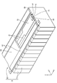
- FIG. FIG. 2 is a perspective view of an electric storage module.
- FIG. 3 is a plan view of the power storage module.
- FIG. 4 is a plan view of the state of FIG. 3 with the outer cover removed.
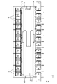
- FIG. 5 is a plan view of FIG. 4 with the cover removed.
- FIG. 6 is an enlarged view of FIG. 5 showing connection between the flexible substrate and the bus bar and connection between the flexible substrate and the circuit board.
- FIG. 7 is an enlarged view of FIG. 5 showing the periphery of the recess of the protector.
- FIG. 8 is a cross-sectional view of the power storage module taken along line AA of FIG. FIG.
- FIG. 9 is a cross-sectional view of the power storage module taken along the line BB in FIG.
- FIG. 10 is a cross-sectional view of the power storage module taken along line CC of FIG.
- FIG. 11 is an enlarged view of FIG. 4 showing the periphery of the recess of the protector.
- FIG. 12 is a perspective view of the cover.
- FIG. 13 is a perspective view of a busbar.
- 14 is a cross-sectional view of a power storage module showing a water cutoff wall according to a second embodiment;
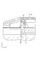
- FIG. 15 is a cross-sectional view of a power storage module showing a closing portion according to a third embodiment;
- a wiring module according to the present disclosure is a wiring module attached to the upper side of a plurality of power storage elements, and includes a bus bar connected to electrode terminals of the plurality of power storage elements, and a bus bar side connection portion provided on the bus bar.
- a flexible substrate connected to the flexible substrate, a circuit substrate connected to the flexible substrate, and a protector on which the bus bar, the flexible substrate, and the circuit substrate are mounted, wherein It is arranged above the upper surface of the side connection portion.
- the circuit board is connected to the busbar-side connecting portion via the flexible board, and the upper surface of the circuit board is arranged above the upper surface of the busbar-side connecting portion. It is possible to suppress the intrusion of condensed water into the
- the flexible substrate includes a wiring portion, a first connection piece that is superimposed and connected to the upper surface of the busbar side connection portion, and a bridge portion that connects the wiring portion and the first connection piece;
- the protector is provided between a wiring surface on which the wiring portion is placed, a busbar installation portion on which the busbar is installed, and between the wiring surface and the busbar installation portion, and penetrates in the vertical direction. and an opening, and at least a portion of the bridge portion is preferably disposed above or inside the opening.
- the wiring surface is arranged above the upper surface of the busbar side connection portion.
- the bridge portion has a notch portion and is provided so as to be able to expand and contract.
- the provision of the notch makes it easier for the condensed water to drain downward from the bridge through the opening. Further, even if the wiring surface and the upper surface of the busbar side connection portion are displaced in the vertical direction, the bridge portion can extend in the vertical direction, so there is no need to form the bridge portion with extra length.
- the protector has a mounting portion to which the circuit board is mounted, the mounting portion has a partition wall surrounding an outer edge of the circuit board, and a recess provided in the partition wall, and the flexible It is preferable that the board includes a second connection piece extending from the wiring part through the recess toward the circuit board, and the second connection piece is overlapped and connected to the upper surface of the circuit board.
- the circuit board is surrounded by the partition wall except for the recess necessary for connecting the flexible board and the circuit board, so that the intrusion of condensed water from the outside of the mounting portion to the circuit board side is suppressed. can do.
- the recess is provided with a waterproof wall that extends upward from the wiring surface and contacts the lower surface of the second connection piece.
- the waterproof wall can suppress the intrusion of condensed water from the wiring surface and the wiring portion into the circuit board.
- a cover is attached to the mounting portion and covers the circuit board from above.
- the cover is provided with a closing portion configured from an elastic member so as to close the recess, and the lower end of the closing portion is in contact with the upper surface of the second connection piece. is preferred.
- the closed portion can prevent water from entering the circuit board from the wiring portion.
- the cover has a cover main body portion arranged above the mounting portion, and an eaves portion projecting from the cover main body portion to the outside of the mounting portion, and the eaves portion extends from the second It is preferable that the connection piece is covered from above, and that the upper surface of the eaves portion is inclined so as to become lower as the distance from the cover body portion increases outward.
- the circuit board has a circuit board side connection portion connected to the second connection piece, and the lower surface of the second connection piece and the upper surface of the circuit board side connection portion are at the same height. is preferred.
- the wiring module described above is a wiring module for a vehicle that is used by being mounted on the vehicle.
- FIG. 1 Embodiment 1 of the present disclosure will be described with reference to FIGS. 1 to 13.
- FIG. The power storage module 10 including the wiring module 20 of the present embodiment is applied to, for example, the power storage pack 2 mounted on the vehicle 1 as shown in FIG.
- the power storage pack 2 is mounted on a vehicle 1 such as an electric vehicle or a hybrid vehicle and used as a drive source for the vehicle 1 .
- vehicle 1 such as an electric vehicle or a hybrid vehicle
- the reference numerals of other members may be omitted.
- an electricity storage pack 2 is arranged near the center of the vehicle 1 .
- a PCU 3 Power Control Unit
- Electricity storage pack 2 and PCU 3 are connected by wire harness 4 .
- the electricity storage pack 2 and the wire harness 4 are connected by a connector (not shown).
- the electricity storage pack 2 has an electricity storage module 10 having a plurality of electricity storage elements 11 .
- the direction indicated by the arrow Z is upward, the direction indicated by the arrow X is forward, and the direction indicated by the arrow Y is leftward.
- the electricity storage pack 2 includes a plurality of electricity storage modules 10 and a housing (not shown) that accommodates the plurality of electricity storage modules 10 therein. Due to the use of the vehicle 1 or the like, the temperatures of the electric storage element 11 , the bus bar 40 , etc., which will be described later, change abruptly. Due to this temperature difference, dew condensation water is likely to occur inside the housing. In the following, a technique for suppressing infiltration of condensed water adhering to the busbars 40 and condensed water adhering to the ceiling surface of the housing in particular to the circuit board 30 will be described.
- the power storage module 10 includes a plurality of power storage elements 11 arranged in a line and a wiring module 20 attached to the upper surfaces of the plurality of power storage elements 11 .
- the storage element 11 has a flat rectangular parallelepiped shape in which a storage element (not shown) is accommodated. As shown in FIG. 7, the storage element 11 has positive and negative electrode terminals 12A and 12B on its upper surface.
- the wiring module 20 includes two flexible substrates 21A and 21B, a circuit substrate 30 connected to the flexible substrates 21A and 21B, a bus bar 40 connected to the storage element 11, the flexible substrates 21A and 21B. 21B and a protector 50 that holds the bus bar 40. Since the two flexible boards 21A and 21B have the same structure, the configuration of the electrical connection between the flexible board 21A and the flexible board 21A will be described in detail below, and the flexible board 21B will be described. may be omitted.
- the wiring module 20 further includes a cover 70 that covers the circuit board 30 from above (see FIGS. 4 and 5) and an outer cover 80 that covers the area outside the cover 70 from above (see FIGS. 2 to 4). .
- the flexible substrate 21A is a flexible sheet-like substrate. As shown in FIG. 6, the flexible substrate 21A has a base film 22 made of an insulating synthetic resin, and a first conductive path 23 (only a portion of which is shown) wired to the base film 22. As shown in FIG. Although not shown, the base film 22 and the first conductive path 23 are further covered with an insulating layer made of an insulating overlay film, coating film, or the like. As materials for the base film 22 and the insulating layer, polyimide (PI), polyethylene terephthalate (PET), or the like is used, for example.
- the first conductive path 23 is made of metal such as copper or copper alloy, and has electrical conductivity. In this embodiment, the first conductive path 23 is routed on one side of the flexible board 21A, and the flexible board 21A is arranged so that the surface on which the first conductive path 23 is routed faces downward.
- the flexible boards 21A and 21B are arranged between the circuit board 30 and the bus bar 40 in the left-right direction (vertical direction in the figure).
- the flexible substrate 21A includes a wiring portion 24 extending in a strip shape in the front-rear direction (horizontal direction in the drawing), a first connection piece 25 provided on the busbar 40 side, and the wiring portion 24 and the first connection piece 25. and a second connection piece 28 extending from the wiring portion 24 to the circuit board 30 side.
- first connection piece 25 is arranged over the upper surface 43A of the busbar-side connection portion 43 of the busbar 40 .
- a first land 23A is formed on the lower surface of the first connection piece 25 to be arranged at the end of the first conductive path 23 .
- No insulating layer is provided below the first land 23A, and the first land 23A is exposed facing downward.
- the first land 23A is electrically connected to the busbar side connection portion 43 by soldering.
- the bridge portion 26 has a notch portion 27 cut in the front-rear direction and has an elongated shape.
- the bridge portion 26 can be extended and contracted in the front-back direction, the up-down direction, and the left-right direction by the notch portion 27 .
- the bridge portion 26 of this embodiment mainly extends in the vertical direction and connects the wiring portion 24 and the first connection piece 25 .
- the bridge portion 26 can absorb the manufacturing tolerances of the bus bar 40, the flexible substrate 21A, the protector 50, etc., and the assembly tolerances therebetween.
- the second connection pieces 28 are strip-shaped and are arranged in the front-rear direction. The second connection pieces 28 are separated by slits 29 . As shown in FIG. 8 , the second connection piece 28 is arranged over the upper surface 30A of the circuit board 30 . A second land 23B is formed on the lower surface 28A of the second connection piece 28 . As shown in FIG. 6, the second land 23B is arranged at the end of the first conductive path 23 opposite to the first land 23A. No insulating layer is provided below the second land 23B, and the second land 23B is also exposed facing downward like the first land 23A. The second land 23B is electrically connected to the circuit board-side connecting portion 33 of the circuit board 30 by soldering (see FIG. 6).
- the circuit board 30 is a rigid board that does not have flexibility. As shown in FIG. 6, the circuit board 30 includes an insulating plate 31 having insulating properties and a second conductive path 32 (only a portion of which is shown) wired on the insulating plate 31 .
- the insulating plate 31 is formed by, for example, impregnating a glass fiber cloth with an epoxy resin and curing the cloth.
- the second conductive path 32 is made of metal such as copper or copper alloy, and has electrical conductivity.
- the circuit board 30 is arranged so that the surface of the insulating plate 31 on which the second conductive path 32 is arranged faces upward.
- the circuit board 30 has a rectangular shape elongated in the front-rear direction.
- Electronic components E and connectors C are mounted on the circuit board 30 .
- Examples of electronic components E include resistors, capacitors, switching elements, and the like.
- the circuit board 30 is electrically connected by a connector C to an external ECU (Electronic Control Unit) (not shown).
- the ECU is equipped with a microcomputer, elements, etc., and has a well-known configuration with functions for detecting the voltage, current, temperature, etc., of the storage elements 11 and controlling the charging and discharging of each storage element 11. belongs to.
- the circuit board 30 of the present embodiment can be provided with a function of monitoring information such as the voltage and temperature of the storage element 11 and transmitting the information to the ECU.
- the circuit board 30 is provided with a locking recess 34 having a concave shape and a through hole 35 penetrating vertically.
- circuit board side connection part As shown in FIG. 6 , a circuit board side connection portion 33 is provided at the end of the second conductive path 32 .
- the second connection piece 28 is superimposed on the upper surface 33A of the circuit board side connection portion 33, and the circuit board side connection portion 33 is soldered to the second land 23B provided on the second connection piece 28. connected by
- the lower surface 28A of the second connection piece 28 and the upper surface 33A of the circuit board side connection portion 33 are designed to have the same height.
- the lower surface 28A of the second connection piece 28 includes the second land 23B.
- Solder (not shown) is provided in advance on either the second land 23B or the circuit board side connection portion 33, and the second land 23B and the circuit board side connection portion 33 are soldered by reflow. shall have been Since the lower surface 28A of the second connection piece 28 and the upper surface 33A of the circuit board side connection portion 33 are at the same height, the solder that connects the second connection piece 28 and the circuit board side connection portion 33 is not subjected to excessive force. Therefore, the reliability of the electrical connection between the flexible board 21A and the circuit board 30 can be improved.
- the bus bar 40 is a member for connecting the electrode terminals 12A and 12B of the adjacent storage elements 11, and is made of a conductive metal plate. Metals forming the bus bar 40 include copper, copper alloys, aluminum, aluminum alloys, stainless steel (SUS), and the like. As shown in FIG. 13 , the busbar 40 includes a rectangular plate-shaped busbar body 41 , two electrode insertion holes 42 vertically penetrating the busbar body 41 , and an outer ( and a bus bar side connection portion 43 projecting rightward or leftward. As shown in FIG. 6, the electrode terminals 12A and 12B are inserted into the electrode insertion holes 42. As shown in FIG. Bus bar 40 and electrode terminals 12A and 12B are electrically connected by welding.
- the upper surface 43A of the busbar side connection portion 43 is provided below the upper surface of the busbar main body portion 41 .
- the upper surface 43 A of the busbar side connection portion 43 is set lower than the wiring surface 52 of the protector 50 and the upper surface 30 A of the circuit board 30 .
- the upper surface 43A of the busbar side connection portion 43 is connected to the first land 23A provided on the lower surface of the first connection piece 25 by soldering.
- the protector 50 is made of insulating synthetic resin and has a plate shape. As shown in FIG. 5, the protector 50 includes a protector main body 51 in the center in the left-right direction, and wiring surfaces provided on both left and right sides of the protector main body 51 on which the wiring portions 24 of the flexible substrates 21A and 21B are placed. 52, and busbar installation portions 53 provided at the right and left ends of the protector 50 and having the busbars 40 installed thereon. A mounting portion 54 to which the circuit board 30 is mounted is provided in the front half portion of the protector body portion 51 .
- the wiring surface 52 is provided extending in the front-rear direction. Partition walls 55 are provided on both left and right sides of the wiring surface 52 .
- the wiring portions 24 of the flexible substrates 21A and 21B are fixed on the wiring surface 52 by adhesive, adhesive tape, heat crimping, or the like, and partitioned by a partition wall 55.
- the partition wall 55 between the flexible board 21A and the circuit board 30 also serves as a partition wall 58 that constitutes the mounting portion 54.
- the protector 50 has an opening 56 extending vertically between the wiring surface 52 and the busbar installation portion 53 (the rim is partially indicated by broken lines).
- the opening 56 is formed so as to include the bridge portion 26 inside the opening 56 when viewed from above.
- the bridge portion 26 is arranged above or inside the opening 56 . Since the bridge portion 26 has an elongated shape with the cutout portion 27 , condensed water adhering to the bridge portion 26 is easily drained downward (that is, toward the power storage element 11 ) through the opening 56 .
- the wiring surface 52 is arranged above the upper surface 43A of the busbar side connection portion 43, so the wiring portion 24 is arranged above the first connection piece 25. As shown in FIG. This makes it difficult for condensed water to enter the wiring portion 24 from the bus bar 40 via the bridge portion 26 that connects the wiring portion 24 and the first connection piece 25 . Since the bridge portion 26 of the present embodiment has the notch portion 27, the wiring portion 24 and the first connection piece 25 are connected by extending by the vertical displacement between the wiring portion 24 and the first connection piece 25. can do. Therefore, it is not necessary to provide the bridge portion 26 with an extra length corresponding to the vertical displacement between the wiring portion 24 and the first connection piece 25, and the usage of the flexible substrates 21A and 21B can be reduced.
- the mounting portion 54 includes partition walls 58 surrounding the outer edge of the circuit board 30 and recesses 59 provided in the partition walls 58 on both left and right sides of the circuit board 30 .
- the inner upper end 59A of the recess 59 of the present embodiment is provided smoothly and continuously to the wiring surface 52 without steps.
- a second connection piece 28 extending from the wiring portion 24 toward the circuit board 30 is inserted into the recess 59 .
- a bottom surface 57 is a surface of the mounting portion 54 with which the lower surface of the circuit board 30 abuts.
- the front end of the mounting portion 54 is provided with a first connector recess 60 to which the connector C is mounted.
- the bottom surface 57 is provided with a locking piece 61 that extends upward and is flexibly deformable in the left-right direction.
- the locking pieces 61 are arranged so as to lock with the locking recesses 34 of the circuit board 30 .
- the mounting portion 54 is provided with a cylindrical positioning protrusion 62 extending upward.
- the positioning projections 62 are inserted through the through holes 35 of the circuit board 30 to position the circuit board 30 on the mounting portion 54 .
- the partition wall 58 is provided with a locking projection 63 projecting inwardly of the mounting portion 54 .
- the busbar installation portion 53 is formed in a frame shape and is configured so that the busbars 40 can be arranged side by side in the front-rear direction.
- the busbar installation portion 53 has an engaging claw 64 and holds the busbar 40 .
- the busbar installation portion 53 has a busbar concave portion 65 that accommodates the busbar side connection portion 43 .
- the busbar side connection portion 43 accommodated in the busbar recessed portion 65 protrudes outward from the busbar mounting portion 53 and is arranged inside the opening 56 .
- the busbar installation portion 53 has a configuration in which a part of the bottom is missing, and the busbars 40 held by the busbar installation portion 53 are electrically connected to the plurality of storage elements 11 . be.
- the cover 70 is made of insulating synthetic resin and is a lid-like member. As shown in FIG. 12, the cover 70 has a cover main body portion 71 that has a rectangular shape when viewed from above, and an eaves portion 72 that protrudes from the cover main body portion 71 in the left-right direction. As shown in FIG. 8, the cover 70 is attached to the mounting portion 54 and configured to cover the circuit board 30 from above. The eaves portion 72 is arranged to protrude outside the mounting portion 54 .
- the eaves portion 72 is configured to cover the concave portion 59 and the second connecting piece 28 from above. Therefore, when the condensed water adhering to the ceiling surface of the housing falls onto the cover 70 from above, it is possible to prevent the condensed water from entering the circuit board 30 .
- an upper surface 72A of the eaves portion 72 is inclined so as to become lower as it goes away from the cover body portion 71 to the outside (left side in the drawing). As a result, the condensed water falling from above the cover 70 can be drained downward toward the wiring portion 24, the wiring surface 52, and the like. Further, since a part of the edge 72B of the eaves portion 72 is arranged above the edge of the opening 56, the condensation water on the upper surface 72A of the eaves portion 72 can be drained through the opening 56 toward the power storage element 11 side. is also possible.
- the cover 70 has a cover-side partition wall 78 extending downward and arranged inside the recess 59 .
- a lower end portion of the cover-side partition wall 78 is arranged so as not to contact the upper surface 28B of the second connection piece 28 .
- the cover-side partition wall 78 is provided so as to be continuous with the partition wall 58 of the mounting portion 54 in the front-rear direction (perpendicular to the plane of the drawing). That is, since the cover-side partition wall 78 is configured to partially close the recessed portion 59 in the left-right direction, it is possible to prevent condensed water from entering the mounting portion 54 .
- a second connector concave portion 73 is provided at the front end portion of the cover main body portion 71 .
- the second connector recess 73 is attached to the upper portion of the connector C attached to the first connector recess 60, and the connector C is surrounded by the first connector recess 60 and the second connector recess 73 without any gap. It is designed to be
- a locking portion 74 that locks with the locking projection 63 is provided on the lower side of the cover main body portion 71 . Thereby, the cover 70 is locked to the mounting portion 54 .
- an engaging projection 75 is provided on the lower side of the cover body portion 71 and arranged between the partition wall 58 and the locking piece 61 . The engaging protrusion 75 positions the cover 70 with respect to the mounting portion 54 , and the locking piece 61 bends toward the partition wall 58 to release the locking between the locking piece 61 and the locking recess 34 of the circuit board 30 . It is restrained.
- stepped portions 76 recessed downward from the upper surface 71A of the cover body portion 71 are provided on the right and left portions of the rear half portion of the cover body portion 71 .
- the stepped portion 76 is provided so as to spread forward and rearward from the eaves portion 72 .
- the stepped portion 76 and the upper surface 71A of the cover body portion 71 are connected by a groove portion 77 .
- the groove portion 77 is recessed further downward than the stepped portion 76 .
- the outer cover 80 is made of insulating synthetic resin and is a lid-shaped member. As shown in FIGS. 2 and 3, the outer cover 80 is a member for covering a part of the cover 70 and the outer part of the wiring module 20 not covered by the cover 70 from above. That is, as shown in FIG. 8, the outer cover 80 covers the wiring portion 24 outside the mounting portion 54, the bus bar 40, and the like from above. Although detailed description is omitted, the outer cover 80 (outer wall portion 82) and the outer edge portion (busbar installation portion 53) of the protector 50 have engagement portions similar to the locking portions 74 and locking projections 63 shown in FIG. A stop structure is provided for each, and the outer cover 80 is attached to the protector 50 .
- the outer cover 80 has an inner wall portion 81 that overlaps the upper surface of the stepped portion 76 of the cover 70, and an outer wall portion 82 that covers the busbar 40 and the busbar installation portion 53 from above. ing.
- a first inclined portion 83 , an intermediate wall portion 84 and a second inclined portion 85 are provided between the inner wall portion 81 and the outer wall portion 82 .
- the intermediate wall portion 84 is provided below the inner wall portion 81 and the outer wall portion 82 .
- the intermediate wall portion 84 is connected to the inner wall portion 81 via the first inclined portion 83 and is connected to the outer wall portion 82 via the second inclined portion 85 .
- the inner end portion of the inner wall portion 81 is provided with an engagement convex portion 86 protruding downward.
- the engagement protrusion 86 engages with the groove 77 of the cover 70 to position the outer cover 80 with respect to the cover 70 .
- the engaging projection 86 and the groove 77 are engaged with each other with a clearance so that after a certain amount of condensed water accumulates in the groove 77, the condensed water enters the inner side of the outer cover 80. It's becoming In this way, the vicinity of the recessed portion 59 of the protector 50 is double covered from above by the outer cover 80 and the cover 70 , so that the condensed water falling from above is less likely to enter the circuit board 30 .
- a projecting wall 87 extending downward is provided on the side of the outer wall portion 82 of the second inclined portion 85 .
- the projecting wall 87 is provided in the vicinity of the busbar installation portion 53 , and the dew condensation water adhering to the busbar 40 and the busbar installation portion 53 is guided downward by the projecting wall 87 and drained downward through the opening 56 . It has become so.
- the first inclined portion 83 is formed with a clearance from the upper surface 72A of the eaves portion 72 . As a result, when condensed water enters between the outer cover 80 and the cover 70 , the condensed water is easily drained by the eaves portion 72 .
- condensed water is collected along the first inclined portion 83 and the second inclined portion 85 on the intermediate wall portion 84 provided lower than the surrounding wall portions.
- Condensed water adhering to the inner side of the outer cover 80 is collected on the lower surface of the intermediate wall portion 84 and is easily drained to the opening 56 below the intermediate wall portion 84, the wiring portion 24, and the like.
- condensed water tends to accumulate on the upper surface of the intermediate wall portion 84 , and does not easily accumulate on the upper surface of the inner wall portion 81 . It becomes difficult to penetrate to the circuit board 30 through.
- the upper surface of the intermediate wall portion 84 has a region (for example, the latter half of the outer cover 80) where the condensed water can escape sufficiently even if the condensed water adheres. not.
- a wiring module 20 according to the first embodiment is a wiring module 20 attached to the upper side of a plurality of storage elements 11, and includes a bus bar 40 connected to electrode terminals 12A and 12B of the plurality of storage elements 11, and a bus bar 40 provided on the bus bar 40.
- the flexible boards 21A and 21B connected to the busbar side connection portions 43, the circuit board 30 connected to the flexible boards 21A and 21B, the busbar 40, the flexible boards 21A and 21B, and the circuit board 30 are placed.
- a protector 50 is provided, and the upper surface 30A of the circuit board 30 is arranged above the upper surface 43A of the busbar side connection portion 43 .
- the circuit board 30 is connected to the busbar side connection portion 43 via the flexible boards 21A and 21B, and the upper surface 30A of the circuit board 30 is arranged above the upper surface 43A of the busbar side connection portion 43. As a result, entry of condensed water from the bus bar 40 into the circuit board 30 can be suppressed.
- the flexible substrates 21A and 21B include the wiring portion 24, the first connection piece 25 that is overlaid and connected to the upper surface 43A of the busbar side connection portion 43, and the wiring portion 24 and the first connection piece 25.
- the protector 50 includes a connecting bridge portion 26 , a wiring surface 52 on which the wiring portion 24 is placed, a busbar installation portion 53 on which the busbars 40 are installed, and the wiring surface 52 and the busbar installation portion 53 . and an opening 56 that is provided therebetween and penetrates in the vertical direction, and at least a portion of the bridge portion 26 is arranged above or inside the opening 56 .
- the wiring surface 52 is arranged above the upper surface 43A of the busbar-side connection portion 43 .
- the condensation water does not enter the wiring portions 24 from the busbar 40 through the bridge portion 26. can be suppressed.
- the bridge part 26 has the notch part 27 and is provided so as to be able to expand and contract.
- provision of the notch portion 27 makes it easier for the condensed water to drain downward from the bridge portion 26 through the opening 56 . Further, even if the wiring surface 52 and the upper surface 43A of the busbar side connection portion 43 are displaced in the vertical direction, the bridge portion 26 can extend in the vertical direction. There is no
- the protector 50 has a mounting portion 54 to which the circuit board 30 is mounted, and the mounting portion 54 includes a partition wall 58 surrounding the outer edge of the circuit board 30 and a concave portion 59 provided in the partition wall 58.
- the flexible boards 21A and 21B have a second connection piece 28 extending from the wiring portion 24 through the recess 59 toward the circuit board 30, the second connection piece 28 being superimposed on the upper surface 30A of the circuit board 30, It is connected.
- the circuit board 30 is surrounded by the partition walls 58 except for the recesses 59 necessary for connecting the flexible boards 21A, 21B and the circuit board 30. Intrusion of condensed water to the side can be suppressed.
- a cover 70 is provided which is attached to the mounting portion 54 and covers the circuit board 30 from above.
- the cover 70 has a cover main body portion 71 arranged above the mounting portion 54, and an eaves portion 72 projecting from the cover main body portion 71 to the outside of the mounting portion 54.
- the eaves portion 72 is , and covers the second connection piece 28 from above, and the upper surface 72A of the eaves portion 72 is inclined so as to become lower as it goes away from the cover body portion 71 to the outside.
- the circuit board 30 includes the circuit board side connection portion 33 connected to the second connection piece 28, and the bottom surface 28A of the second connection piece 28 and the top surface 33A of the circuit board side connection portion 33 are the same. It is said to be high.
- connection reliability between the flexible boards 21A, 21B and the circuit board 30 can be improved.
- Embodiment 2 of the present disclosure will be described with reference to FIG. 14 .
- the wiring module 120 according to the second embodiment is configured in the same manner as in the first embodiment except that the protector 150 has a water stop wall 151. Therefore, the same members and effects as those in the first embodiment will not be described. is omitted.
- a plurality of identical members only some members may be given reference numerals, and the reference numerals of other members may be omitted.
- a waterproof wall 151 extending upward from the wiring surface 52 is provided inside the recess 159 of the protector 150 . Therefore, the water stop wall 151 makes it difficult for condensed water to enter the circuit board 30 from the wiring surface 52 . Also, the upper end portion 151A of the water cutoff wall 151 contacts the lower surface 28A of the second connection piece 28 that is passed through the recess 159 . Therefore, the wiring portion 24 is inclined downward from the circuit board 30 side toward the opening 56 , and it is possible to suppress the entry of condensed water from the wiring portion 24 into the circuit board 30 .
- the recess 159 is provided with a water cutoff wall 151 that extends upward from the wiring surface 52 and contacts the lower surface 28A of the second connection piece 28 .
- the water stop wall 151 can suppress the entry of condensed water from the wiring surface 52 and the wiring portion 24 into the circuit board 30 .
- Embodiment 3 of the present disclosure will be described with reference to FIG. 15 .
- the wiring module 220 according to the third embodiment is configured in the same manner as in the first embodiment except that the cover 270 has a closing portion 271. Therefore, the same members and effects as in the first embodiment will not be described. omitted.
- a plurality of identical members only some members may be given reference numerals, and the reference numerals of other members may be omitted.
- the cover-side partition wall 78 of the cover 270 is attached with a closing portion 271 made of an elastic member such as sponge or rubber. Since the closing portion 271 is made of an elastic member, the lower end portion 271A of the closing portion 271 can be provided so as to contact the upper surface 28B of the second connecting piece 28 . As a result, the closing portion 271 can block the entire recessed portion 59 in the left-right direction, thereby suppressing intrusion of condensed water from the wiring portion 24 into the circuit board 30 . Further, when the closing portion 271 is made of a sponge, it is possible to prevent the condensed water from entering the circuit board 30 by absorbing the condensed water with the sponge.
- an elastic member such as sponge or rubber
- the cover 270 is provided with a closing portion 271 that is arranged to close the recess 59 and is made of an elastic member. in contact.
- the closing portion 271 can prevent water from entering the circuit board 30 from the wiring portion 24 .
- a rigid board is used as the circuit board 30, but the circuit board is not limited to this, and the circuit board may be a flexible board.
- the bus bar 40 and the flexible substrates 21A and 21B are directly connected, but the present invention is not limited to this. It may be configured to be connected by (3)
- the outer cover 80 is provided outside the cover 70. However, the present invention is not limited to this, and a configuration without the outer cover may be employed.
Landscapes
- Chemical & Material Sciences (AREA)
- Chemical Kinetics & Catalysis (AREA)
- Electrochemistry (AREA)
- General Chemical & Material Sciences (AREA)
- Engineering & Computer Science (AREA)
- Mechanical Engineering (AREA)
- Battery Mounting, Suspending (AREA)
- Connection Of Batteries Or Terminals (AREA)
- Structure Of Printed Boards (AREA)
- Combinations Of Printed Boards (AREA)
Priority Applications (2)
| Application Number | Priority Date | Filing Date | Title |
|---|---|---|---|
| CN202280008730.9A CN116670913A (zh) | 2021-01-19 | 2022-01-06 | 配线模块 |
| US18/270,582 US20240063497A1 (en) | 2021-01-19 | 2022-01-06 | Wiring module |
Applications Claiming Priority (2)
| Application Number | Priority Date | Filing Date | Title |
|---|---|---|---|
| JP2021-006350 | 2021-01-19 | ||
| JP2021006350A JP7524772B2 (ja) | 2021-01-19 | 2021-01-19 | 配線モジュール |
Publications (1)
| Publication Number | Publication Date |
|---|---|
| WO2022158293A1 true WO2022158293A1 (ja) | 2022-07-28 |
Family
ID=82548805
Family Applications (1)
| Application Number | Title | Priority Date | Filing Date |
|---|---|---|---|
| PCT/JP2022/000173 Ceased WO2022158293A1 (ja) | 2021-01-19 | 2022-01-06 | 配線モジュール |
Country Status (4)
| Country | Link |
|---|---|
| US (1) | US20240063497A1 (https=) |
| JP (2) | JP7524772B2 (https=) |
| CN (1) | CN116670913A (https=) |
| WO (1) | WO2022158293A1 (https=) |
Families Citing this family (1)
| Publication number | Priority date | Publication date | Assignee | Title |
|---|---|---|---|---|
| EP4152485A4 (en) * | 2021-07-30 | 2023-05-31 | Contemporary Amperex Technology Co., Limited | BATTERY CASE, BATTERY, POWER APPLICATION DEVICE AND METHOD AND APPARATUS FOR MAKING A BATTERY |
Citations (2)
| Publication number | Priority date | Publication date | Assignee | Title |
|---|---|---|---|---|
| WO2015107583A1 (ja) * | 2014-01-17 | 2015-07-23 | 三洋電機株式会社 | 電源装置 |
| WO2015159524A1 (ja) * | 2014-04-17 | 2015-10-22 | パナソニックIpマネジメント株式会社 | バスバーモジュール、バッテリ監視モジュールおよびバッテリモジュール |
Family Cites Families (8)
| Publication number | Priority date | Publication date | Assignee | Title |
|---|---|---|---|---|
| JP5702947B2 (ja) | 2010-04-22 | 2015-04-15 | 矢崎総業株式会社 | 配線材 |
| US9905832B2 (en) * | 2012-09-03 | 2018-02-27 | Autonetworks Technologies, Ltd. | Battery wiring module |
| JP6164489B2 (ja) | 2014-01-21 | 2017-07-19 | 株式会社オートネットワーク技術研究所 | 配線モジュール |
| CN109301634B (zh) | 2017-07-24 | 2020-06-19 | 莫仕连接器(成都)有限公司 | 电池连接模块 |
| JP6691178B2 (ja) | 2018-07-10 | 2020-04-28 | 矢崎総業株式会社 | プロテクタ、及び、バスバモジュール |
| JP7385807B2 (ja) | 2018-10-02 | 2023-11-24 | 株式会社オートネットワーク技術研究所 | フレキシブルプリント基板、及び配線モジュール |
| JP7029645B2 (ja) * | 2018-10-02 | 2022-03-04 | 株式会社オートネットワーク技術研究所 | フレキシブルプリント基板、配線部材、蓄電モジュールおよび接続モジュール |
| JP7253525B2 (ja) | 2020-12-21 | 2023-04-06 | プライムプラネットエナジー&ソリューションズ株式会社 | 蓄電モジュール |
-
2021
- 2021-01-19 JP JP2021006350A patent/JP7524772B2/ja active Active
-
2022
- 2022-01-06 US US18/270,582 patent/US20240063497A1/en active Pending
- 2022-01-06 CN CN202280008730.9A patent/CN116670913A/zh active Pending
- 2022-01-06 WO PCT/JP2022/000173 patent/WO2022158293A1/ja not_active Ceased
-
2023
- 2023-02-24 JP JP2023026956A patent/JP7517494B2/ja active Active
Patent Citations (2)
| Publication number | Priority date | Publication date | Assignee | Title |
|---|---|---|---|---|
| WO2015107583A1 (ja) * | 2014-01-17 | 2015-07-23 | 三洋電機株式会社 | 電源装置 |
| WO2015159524A1 (ja) * | 2014-04-17 | 2015-10-22 | パナソニックIpマネジメント株式会社 | バスバーモジュール、バッテリ監視モジュールおよびバッテリモジュール |
Also Published As
| Publication number | Publication date |
|---|---|
| US20240063497A1 (en) | 2024-02-22 |
| JP2023071799A (ja) | 2023-05-23 |
| JP2022110745A (ja) | 2022-07-29 |
| CN116670913A (zh) | 2023-08-29 |
| JP7517494B2 (ja) | 2024-07-17 |
| JP7524772B2 (ja) | 2024-07-30 |
Similar Documents
| Publication | Publication Date | Title |
|---|---|---|
| JP7598541B2 (ja) | 配線モジュール | |
| JP6790923B2 (ja) | 接続モジュール | |
| US20240014501A1 (en) | Wiring module | |
| US7841869B2 (en) | Connector for board and electrical junction box | |
| US9853331B2 (en) | Cover for batteries | |
| JP7569500B2 (ja) | 配線モジュール及びバスバーユニット | |
| US12144107B2 (en) | Substrate connection structure and vehicle wiring module | |
| JP7517494B2 (ja) | フレキシブル基板及び配線モジュール | |
| US20240006724A1 (en) | Bus bar module | |
| US10582632B2 (en) | Board unit | |
| US20250202082A1 (en) | Wiring module | |
| US20250364697A1 (en) | Wiring module | |
| US12237598B2 (en) | In-vehicle wiring module | |
| JP7560509B2 (ja) | バスバモジュール | |
| JP7839470B2 (ja) | 配線モジュール | |
| JP7684270B2 (ja) | バスバモジュール | |
| US20260113890A1 (en) | Electrical connection unit | |
| JP7684269B2 (ja) | バスバモジュール | |
| CN115621636B (zh) | 蓄电装置 | |
| US20260058322A1 (en) | Bus bar module case and bus bar module | |
| US20260128559A1 (en) | Electrical connection unit | |
| CN121602129A (zh) | 线束和汇流条模块 | |
| WO2024116884A1 (ja) | バスバモジュール | |
| WO2022163420A1 (ja) | 配線モジュール |
Legal Events
| Date | Code | Title | Description |
|---|---|---|---|
| 121 | Ep: the epo has been informed by wipo that ep was designated in this application |
Ref document number: 22742418 Country of ref document: EP Kind code of ref document: A1 |
|
| WWE | Wipo information: entry into national phase |
Ref document number: 202280008730.9 Country of ref document: CN |
|
| WWE | Wipo information: entry into national phase |
Ref document number: 18270582 Country of ref document: US |
|
| NENP | Non-entry into the national phase |
Ref country code: DE |
|
| 122 | Ep: pct application non-entry in european phase |
Ref document number: 22742418 Country of ref document: EP Kind code of ref document: A1 |