WO2022158185A1 - Dispositif de traitement d'informations, procédé de traitement d'informations, programme et dispositif mobile - Google Patents
Dispositif de traitement d'informations, procédé de traitement d'informations, programme et dispositif mobile Download PDFInfo
- Publication number
- WO2022158185A1 WO2022158185A1 PCT/JP2021/046500 JP2021046500W WO2022158185A1 WO 2022158185 A1 WO2022158185 A1 WO 2022158185A1 JP 2021046500 W JP2021046500 W JP 2021046500W WO 2022158185 A1 WO2022158185 A1 WO 2022158185A1
- Authority
- WO
- WIPO (PCT)
- Prior art keywords
- map
- creation
- unit
- information processing
- vehicle
- Prior art date
Links
- 230000010365 information processing Effects 0.000 title claims description 46
- 238000003672 processing method Methods 0.000 title claims description 4
- 230000008859 change Effects 0.000 claims description 61
- 238000000034 method Methods 0.000 claims description 34
- 238000013507 mapping Methods 0.000 claims description 13
- 230000007613 environmental effect Effects 0.000 claims description 4
- 238000004891 communication Methods 0.000 description 73
- 238000012545 processing Methods 0.000 description 67
- 238000007726 management method Methods 0.000 description 35
- 238000010276 construction Methods 0.000 description 32
- 230000033001 locomotion Effects 0.000 description 30
- 238000005516 engineering process Methods 0.000 description 25
- 238000010586 diagram Methods 0.000 description 15
- 230000008569 process Effects 0.000 description 14
- 230000007246 mechanism Effects 0.000 description 11
- 238000001514 detection method Methods 0.000 description 8
- 230000000007 visual effect Effects 0.000 description 7
- 230000006870 function Effects 0.000 description 6
- 230000003993 interaction Effects 0.000 description 6
- 238000005259 measurement Methods 0.000 description 6
- 238000009825 accumulation Methods 0.000 description 5
- 230000009471 action Effects 0.000 description 5
- 230000010391 action planning Effects 0.000 description 4
- 230000004927 fusion Effects 0.000 description 4
- 238000012986 modification Methods 0.000 description 4
- 230000004048 modification Effects 0.000 description 4
- 238000004458 analytical method Methods 0.000 description 3
- 230000005540 biological transmission Effects 0.000 description 3
- 238000011161 development Methods 0.000 description 3
- 230000018109 developmental process Effects 0.000 description 3
- 238000012544 monitoring process Methods 0.000 description 3
- 230000001133 acceleration Effects 0.000 description 2
- 230000000694 effects Effects 0.000 description 2
- 238000003384 imaging method Methods 0.000 description 2
- 230000007774 longterm Effects 0.000 description 2
- 230000003287 optical effect Effects 0.000 description 2
- 230000002265 prevention Effects 0.000 description 2
- 230000011218 segmentation Effects 0.000 description 2
- 206010062519 Poor quality sleep Diseases 0.000 description 1
- 230000004913 activation Effects 0.000 description 1
- 230000003044 adaptive effect Effects 0.000 description 1
- 239000010426 asphalt Substances 0.000 description 1
- 230000003190 augmentative effect Effects 0.000 description 1
- 239000003086 colorant Substances 0.000 description 1
- 238000002485 combustion reaction Methods 0.000 description 1
- 238000013500 data storage Methods 0.000 description 1
- 238000005034 decoration Methods 0.000 description 1
- 238000007499 fusion processing Methods 0.000 description 1
- 238000009434 installation Methods 0.000 description 1
- 230000010354 integration Effects 0.000 description 1
- 230000004807 localization Effects 0.000 description 1
- 238000012423 maintenance Methods 0.000 description 1
- 230000000116 mitigating effect Effects 0.000 description 1
- 238000010295 mobile communication Methods 0.000 description 1
- 230000001151 other effect Effects 0.000 description 1
- 230000001172 regenerating effect Effects 0.000 description 1
- 239000004576 sand Substances 0.000 description 1
- 239000004065 semiconductor Substances 0.000 description 1
- 230000015541 sensory perception of touch Effects 0.000 description 1
- 230000035939 shock Effects 0.000 description 1
- 230000003068 static effect Effects 0.000 description 1
Images


Classifications
-
- G—PHYSICS
- G01—MEASURING; TESTING
- G01C—MEASURING DISTANCES, LEVELS OR BEARINGS; SURVEYING; NAVIGATION; GYROSCOPIC INSTRUMENTS; PHOTOGRAMMETRY OR VIDEOGRAMMETRY
- G01C21/00—Navigation; Navigational instruments not provided for in groups G01C1/00 - G01C19/00
- G01C21/38—Electronic maps specially adapted for navigation; Updating thereof
- G01C21/3804—Creation or updating of map data
-
- G—PHYSICS
- G05—CONTROLLING; REGULATING
- G05D—SYSTEMS FOR CONTROLLING OR REGULATING NON-ELECTRIC VARIABLES
- G05D1/00—Control of position, course, altitude or attitude of land, water, air or space vehicles, e.g. using automatic pilots
- G05D1/02—Control of position or course in two dimensions
- G05D1/021—Control of position or course in two dimensions specially adapted to land vehicles
- G05D1/0268—Control of position or course in two dimensions specially adapted to land vehicles using internal positioning means
- G05D1/0274—Control of position or course in two dimensions specially adapted to land vehicles using internal positioning means using mapping information stored in a memory device
-
- G—PHYSICS
- G01—MEASURING; TESTING
- G01C—MEASURING DISTANCES, LEVELS OR BEARINGS; SURVEYING; NAVIGATION; GYROSCOPIC INSTRUMENTS; PHOTOGRAMMETRY OR VIDEOGRAMMETRY
- G01C21/00—Navigation; Navigational instruments not provided for in groups G01C1/00 - G01C19/00
- G01C21/38—Electronic maps specially adapted for navigation; Updating thereof
- G01C21/3863—Structures of map data
- G01C21/387—Organisation of map data, e.g. version management or database structures
- G01C21/3881—Tile-based structures
-
- G—PHYSICS
- G05—CONTROLLING; REGULATING
- G05D—SYSTEMS FOR CONTROLLING OR REGULATING NON-ELECTRIC VARIABLES
- G05D1/00—Control of position, course, altitude or attitude of land, water, air or space vehicles, e.g. using automatic pilots
- G05D1/02—Control of position or course in two dimensions
- G05D1/021—Control of position or course in two dimensions specially adapted to land vehicles
- G05D1/0268—Control of position or course in two dimensions specially adapted to land vehicles using internal positioning means
- G05D1/0272—Control of position or course in two dimensions specially adapted to land vehicles using internal positioning means comprising means for registering the travel distance, e.g. revolutions of wheels
-
- G—PHYSICS
- G09—EDUCATION; CRYPTOGRAPHY; DISPLAY; ADVERTISING; SEALS
- G09B—EDUCATIONAL OR DEMONSTRATION APPLIANCES; APPLIANCES FOR TEACHING, OR COMMUNICATING WITH, THE BLIND, DEAF OR MUTE; MODELS; PLANETARIA; GLOBES; MAPS; DIAGRAMS
- G09B29/00—Maps; Plans; Charts; Diagrams, e.g. route diagram
-
- G—PHYSICS
- G09—EDUCATION; CRYPTOGRAPHY; DISPLAY; ADVERTISING; SEALS
- G09B—EDUCATIONAL OR DEMONSTRATION APPLIANCES; APPLIANCES FOR TEACHING, OR COMMUNICATING WITH, THE BLIND, DEAF OR MUTE; MODELS; PLANETARIA; GLOBES; MAPS; DIAGRAMS
- G09B29/00—Maps; Plans; Charts; Diagrams, e.g. route diagram
- G09B29/10—Map spot or coordinate position indicators; Map reading aids
Definitions
- the present technology relates to an information processing device, an information processing method, a program, and a mobile device, and more specifically, to an information processing device and the like capable of favorably creating a map used in the mobile device.
- mobile devices such as robots and cars, which are autonomous moving bodies, are known to move while estimating their own position.
- the mobile device performs a process of matching with a pre-created self-position estimation map to estimate where it is on the map, and movement is controlled based on the result.
- it may be difficult to have a wide-range map and to develop the map on the memory.
- Patent Document 1 discloses that a map for self-position estimation is simply grid-divided into a narrow-range map and possessed.
- the purpose of this technology is to facilitate the creation of maps used in mobile devices.
- the concept of this technology is a mapping unit that generates at least a first map and a second map based on the first recognition result of the surrounding environment; an information processing apparatus comprising: a created map switching determination unit that determines termination of creation of the first map and start of creation of the second map based on a second recognition result of the surrounding environment.
- the map creation unit creates at least a first map and a second map based on the first recognition result of the surrounding environment.
- the first map and the second map may be maps of adjacent regions.
- the first map and the second map may each be a map whose range is an area having similar environmental information.
- the map created by the map creation unit may be a map for self-position estimation.
- the creation map switching determination unit determines the end of creation of the first map and the start of creation of the second map.
- the second recognition result may include the amount of change in the current light tone.
- the second recognition result may include the amount of change in the current distance to the surrounding object.
- the second recognition result may include the amount of change in the current amount of vibration.
- the second recognition result may include the amount of change in the current tilt.
- the present technology based on the recognition result of the surrounding environment, it is determined whether the creation of the first map is finished and the creation of the second map is started. As a result, the division of the map used in the mobile device is performed based on the surrounding environment, so that management and updating can be performed well.
- the created map switching determination unit determines whether to end the creation of the first map and start the creation of the second map further based on the map creation status in the map creation unit. may be made.
- the division of the map used in the mobile device is further based on the map creation situation, for example, a wide area suitable for the performance of the mobile device (map switching speed performance, map development performance on memory, etc.) can be obtained. can create a map of
- the map creation status may include the amount of map creation.
- the amount of map creation may be determined based on the distance traveled by the mobile device including the information processing device to create the current map. Further, here, for example, the amount of map creation may be determined based on the data amount of the map currently being created. Further, in this case, the map creation status may include a node placement instruction by the user.
- the created map switching determination unit may determine the end of creation of the first map and the start of creation of the second map further based on the user's operation.
- the division of the map used in the mobile device is performed based on the user's intention, and the map can be constructed as intended by the user.
- a map holding unit that holds a plurality of maps including at least a first map and a second map
- a use map switching determination unit that switches between the plurality of maps based on changes in the surrounding environment.
- a self-location estimator that estimates the self-location based on the map being used. This makes it possible to appropriately switch the map used for self-position estimation based on changes in the surrounding environment.
- Another concept of this technology is a mapping procedure for generating at least a first map and a second map based on a first recognition result of the surrounding environment; a created map switching determination procedure for determining the end of creation of the first map and the start of creation of the second map based on a second recognition result of the surrounding environment.
- mapping unit that generates at least a first map and a second map based on the first recognition result of the surrounding environment
- a program for functioning as a created map switching determination unit that determines the end of creation of the first map and the start of creation of the second map based on a second recognition result of the surrounding environment.
- a mobile device comprising an information processing device,
- the information processing device is a mapping unit that generates at least a first map and a second map based on the first recognition result of the surrounding environment; a created map switching determination unit that determines termination of creation of the first map and start of creation of the second map based on a second recognition result of the surrounding environment.
- FIG. 1 is a block diagram showing a configuration example of a vehicle control system, which is an example of a mobile device control system to which the present technology can be applied;
- FIG. FIG. 4 is a diagram showing an example of a sensing area by an external recognition sensor;
- FIG. 3 is a block diagram showing a configuration example of a map creation processing unit in a self-localization system of a mobile device as an autonomous mobile body such as a robot or a car;
- FIG. 10 is a diagram for explaining an example of creating a map for self-position estimation in an implementation environment in which two rooms A and B with different surrounding environments are connected by a door;
- FIG. 4 is a diagram for explaining an outline of processing for creating a map for self-position estimation according to the present technology;
- FIG. 10 is a diagram for explaining an example of processing for creating a map for self-position estimation when the implementation environment is a shopping mall;
- FIG. 10 is a diagram for explaining an example of processing for creating a map for self-position estimation in a case where the implementation environment is a road and a parking space adjacent thereto;
- FIG. 10 is a diagram for explaining an example of processing for creating a map for self-position estimation in a case where the implementation environment is two construction sites and a slope connecting them;
- FIG. 10 is a diagram for explaining an example of self-position estimation map creation processing when the implementation environment is an office;
- FIG. 10 is a diagram for explaining an example of self-position estimation map creation processing when the implementation environment is an office;
- FIG. 10 is a diagram for explaining an example of processing for creating a map for self-position estimation when the implementation environment is a factory; It is a figure which shows an example of the area
- 4 is a flowchart showing an overview of map creation operation by a map creation processing unit;
- FIG. 4 is a block diagram showing a configuration example of a self-localization processing unit in a self-localization system of a mobile device as an autonomous mobile body such as a robot and a car; It is a block diagram which shows the structural example of the hardware of a computer.
- FIG. 1 is a block diagram showing a configuration example of a vehicle control system 11, which is an example of a mobile device control system to which the present technology can be applied.
- the vehicle control system 11 is provided in the vehicle 1 and performs processing related to driving support and automatic driving of the vehicle 1.
- the vehicle control system 11 includes a vehicle control ECU (Electronic Control Unit) 21, a communication unit 22, a map information accumulation unit 23, a GNSS (Global Navigation Satellite System) reception unit 24, an external recognition sensor 25, an in-vehicle sensor 26, a vehicle sensor 27, It has a recording unit 28 , a driving support/automatic driving control unit 29 , a DMS (Driver Monitoring System) 30 , an HMI (Human Machine Interface) 31 , and a vehicle control unit 32 .
- vehicle control ECU Electronic Control Unit
- a communication unit 22 a communication unit 22
- a map information accumulation unit 23 a GNSS (Global Navigation Satellite System) reception unit 24
- an external recognition sensor 25
- an in-vehicle sensor 26 a vehicle sensor 27, It has a recording unit 28 , a driving support/automatic driving control unit 29 , a DMS (Driver Monitoring System) 30 , an HMI (Human Machine Interface) 31 , and a vehicle control unit 32 .
- DMS Driver Monitoring System
- Vehicle control ECU 21, communication unit 22, map information storage unit 23, GNSS reception unit 24, external recognition sensor 25, in-vehicle sensor 26, vehicle sensor 27, recording unit 28, driving support/automatic driving control unit 29, driver monitoring system (DMS ) 30 , a human machine interface (HMI) 31 , and a vehicle control unit 32 are communicatively connected to each other via a communication network 41 .
- the communication network 41 is, for example, a CAN (Controller Area Network), LIN (Local Interconnect Network), LAN (Local Area Network), FlexRay (registered trademark), Ethernet (registered trademark), and other digital two-way communication standards. It is composed of a communication network, a bus, and the like.
- the communication network 41 may be used differently depending on the type of data to be communicated. For example, CAN is applied for data related to vehicle control, and Ethernet is applied for large-capacity data.
- each part of the vehicle control system 11 performs wireless communication assuming relatively short-range communication such as near field communication (NFC (Near Field Communication)) or Bluetooth (registered trademark) without going through the communication network 41. may be connected directly using NFC (Near Field Communication) or Bluetooth (registered trademark) without going through the communication network 41.
- relatively short-range communication such as near field communication (NFC (Near Field Communication)) or Bluetooth (registered trademark)
- the vehicle control ECU 21 is composed of various processors such as a CPU (Central Processing Unit) and an MPU (Micro Processing Unit).
- the vehicle control ECU 21 controls all or part of the functions of the vehicle control system 11 .
- the communication unit 22 communicates with various devices inside and outside the vehicle, other vehicles, servers, base stations, etc., and transmits and receives various data. At this time, the communication unit 22 can perform communication using a plurality of communication methods.
- the communication unit 22 is, for example, a wireless communication system such as 5G (5th generation mobile communication system), LTE (Long Term Evolution), DSRC (Dedicated Short Range Communications), via a base station or access point, on the external network communicates with a server (hereinafter referred to as an external server) located in the 5G (5th generation mobile communication system), LTE (Long Term Evolution), DSRC (Dedicated Short Range Communications), via a base station or access point, on the external network communicates with a server (hereinafter referred to as an external server) located in the
- the external network with which the communication unit 22 communicates is, for example, the Internet, a cloud network, or a business-specific network.
- the communication method for communicating with the external network by the communication unit 22 is not particularly limited as long as it is a wireless communication method that enables digital two-way communication at a predetermined communication speed or higher and at a predetermined distance or longer.
- the communication unit 22 can communicate with terminals existing in the vicinity of the own vehicle using P2P (Peer To Peer) technology.
- Terminals in the vicinity of one's own vehicle are, for example, terminals worn by pedestrians, bicycles, and other moving objects that move at relatively low speeds, terminals installed at fixed locations such as stores, or MTC (Machine Type Communication ) terminal.
- V2X communication is, for example, vehicle-to-vehicle communication with other vehicles, vehicle-to-infrastructure communication with roadside equipment, etc., vehicle-to-home communication , and communication between the vehicle and others, such as vehicle-to-pedestrian communication with a terminal or the like possessed by a pedestrian.
- the communication unit 22 can receive from the outside a program for updating the software that controls the operation of the vehicle control system 11 (Over The Air).
- the communication unit 22 can also receive map information, traffic information, information around the vehicle 1, and the like from the outside.
- the communication unit 22 can transmit information about the vehicle 1, information about the surroundings of the vehicle 1, and the like to the outside.
- the information about the vehicle 1 that the communication unit 22 transmits to the outside includes, for example, data indicating the state of the vehicle 1, recognition results by the recognition unit 73, and the like.
- the communication unit 22 performs communication corresponding to a vehicle emergency call system such as e-call.
- the communication with the inside of the vehicle that can be performed by the communication unit 22 will be described schematically.
- the communication unit 22 can communicate with each device in the vehicle using, for example, wireless communication.
- the communication unit 22 performs wireless communication with devices in the vehicle using a communication method such as wireless LAN, Bluetooth, NFC, and WUSB (Wireless USB) that enables digital two-way communication at a communication speed higher than a predetermined value. can be done.
- the communication unit 22 can also communicate with each device in the vehicle using wired communication.
- the communication unit 22 can communicate with each device in the vehicle by wired communication via a cable connected to a connection terminal (not shown).
- the communication unit 22 performs digital two-way communication at a predetermined communication speed or higher through wired communication such as USB (Universal Serial Bus), HDMI (High-Definition Multimedia Interface) (registered trademark), and MHL (Mobile High-definition Link). can communicate with each device in the vehicle.
- USB Universal Serial Bus
- HDMI High-Definition Multimedia Interface
- MHL Mobile High-definition Link
- equipment in the vehicle refers to equipment that is not connected to the communication network 41 in the vehicle, for example.
- in-vehicle devices include mobile devices and wearable devices possessed by passengers such as drivers, information devices that are brought into the vehicle and temporarily installed, and the like.
- the communication unit 22 receives electromagnetic waves transmitted by a road traffic information communication system (VICS (Vehicle Information and Communication System) (registered trademark)) such as radio wave beacons, optical beacons, and FM multiplex broadcasting.
- VICS Vehicle Information and Communication System
- radio wave beacons such as radio wave beacons, optical beacons, and FM multiplex broadcasting.
- the map information accumulation unit 23 accumulates one or both of the map obtained from the outside and the map created by the vehicle 1. For example, the map information accumulation unit 23 accumulates a three-dimensional high-precision map, a global map covering a wide area, and the like, which is lower in accuracy than the high-precision map.
- High-precision maps are, for example, dynamic maps, point cloud maps, and vector maps.
- the dynamic map is, for example, a map consisting of four layers of dynamic information, quasi-dynamic information, quasi-static information, and static information, and is provided to the vehicle 1 from an external server or the like.
- a point cloud map is a map composed of a point cloud (point cloud data).
- the vector map refers to a map adapted to ADAS (Advanced Driver Assistance System) in which traffic information such as lane and signal positions are associated with a point cloud map.
- ADAS Advanced Driver Assistance System
- the point cloud map and the vector map may be provided from an external server or the like, and based on the sensing results of the radar 52, LiDAR 53, etc., the vehicle 1 as a map for matching with a local map described later. It may be created and stored in the map information storage unit 23 . Further, when a high-precision map is provided from an external server or the like, in order to reduce the communication capacity, map data of, for example, several hundred meters square, regarding the planned route that the vehicle 1 will travel from now on, is acquired from the external server or the like. .
- the position information acquisition unit 24 receives GNSS signals from GNSS (Global Navigation Satellite System) satellites and acquires position information of the vehicle 1 .
- the received GNSS signal is supplied to the driving support/automatic driving control unit 29 .
- the position information acquisition unit 24 is not limited to the method using the GNSS signal, and may acquire the position information using, for example, a beacon.
- the external recognition sensor 25 includes various sensors used for recognizing situations outside the vehicle 1 and supplies sensor data from each sensor to each part of the vehicle control system 11 .
- the type and number of sensors included in the external recognition sensor 25 are arbitrary.
- the external recognition sensor 25 includes a camera 51, a radar 52, a LiDAR (Light Detection and Ranging, Laser Imaging Detection and Ranging) 53, and an ultrasonic sensor 54.
- the configuration is not limited to this, and the external recognition sensor 25 may be configured to include one or more types of sensors among the camera 51 , radar 52 , LiDAR 53 , and ultrasonic sensor 54 .
- the number of cameras 51, radars 52, LiDARs 53, and ultrasonic sensors 54 is not particularly limited as long as it is the number that can be installed in the vehicle 1 in practice.
- the type of sensor provided in the external recognition sensor 25 is not limited to this example, and the external recognition sensor 25 may be provided with other types of sensors. An example of the sensing area of each sensor included in the external recognition sensor 25 will be described later.
- the shooting method of the camera 51 is not particularly limited as long as it is a shooting method that enables distance measurement.
- the camera 51 may be a ToF (Time Of Flight) camera, a stereo camera, a monocular camera, an infrared camera, or any other type of camera as required.
- the camera 51 is not limited to this, and may simply acquire a photographed image regardless of distance measurement.
- the external recognition sensor 25 can include an environment sensor for detecting the environment with respect to the vehicle 1.
- the environment sensor is a sensor for detecting the environment such as weather, climate, brightness, etc., and can include various sensors such as raindrop sensors, fog sensors, sunshine sensors, snow sensors, and illuminance sensors.
- the external recognition sensor 25 includes a microphone used for detecting the sound around the vehicle 1 and the position of the sound source.
- the in-vehicle sensor 26 includes various sensors for detecting information inside the vehicle, and supplies sensor data from each sensor to each part of the vehicle control system 11 .
- the types and number of various sensors included in the in-vehicle sensor 26 are not particularly limited as long as they are realistically installable in the vehicle 1 .
- the in-vehicle sensor 26 can include one or more sensors among cameras, radar, seating sensors, steering wheel sensors, microphones, and biosensors.
- the camera provided in the in-vehicle sensor 26 for example, cameras of various shooting methods capable of distance measurement, such as a ToF camera, a stereo camera, a monocular camera, and an infrared camera, can be used.
- the camera included in the in-vehicle sensor 26 is not limited to this, and may simply acquire a photographed image regardless of distance measurement.
- the biosensors included in the in-vehicle sensor 26 are provided, for example, in seats, steering wheels, etc., and detect various biometric information of passengers such as the driver.
- the vehicle sensor 27 includes various sensors for detecting the state of the vehicle 1, and supplies sensor data from each sensor to each section of the vehicle control system 11.
- the types and number of various sensors included in the vehicle sensor 27 are not particularly limited as long as they can be installed in the vehicle 1 realistically.
- the vehicle sensor 27 includes a speed sensor, an acceleration sensor, an angular velocity sensor (gyro sensor), and an inertial measurement unit (IMU (Inertial Measurement Unit)) integrating them.
- the vehicle sensor 27 includes a steering angle sensor that detects the steering angle of the steering wheel, a yaw rate sensor, an accelerator sensor that detects the amount of operation of the accelerator pedal, and a brake sensor that detects the amount of operation of the brake pedal.
- the vehicle sensor 27 includes a rotation sensor that detects the number of rotations of an engine or a motor, an air pressure sensor that detects tire air pressure, a slip rate sensor that detects a tire slip rate, and a wheel speed sensor that detects the rotational speed of a wheel.
- a sensor is provided.
- the vehicle sensor 27 includes a battery sensor that detects the remaining battery level and temperature, and an impact sensor that detects external impact.
- the recording unit 28 includes at least one of a nonvolatile storage medium and a volatile storage medium, and stores data and programs.
- the recording unit 28 is used, for example, as EEPROM (Electrically Erasable Programmable Read Only Memory) and RAM (Random Access Memory). And a magneto-optical storage device can be applied.
- the recording unit 28 records various programs and data used by each unit of the vehicle control system 11 .
- the recording unit 28 includes an EDR (Event Data Recorder) and a DSSAD (Data Storage System for Automated Driving), and records information on the vehicle 1 before and after an event such as an accident and biometric information acquired by the in-vehicle sensor 26. .
- EDR Event Data Recorder
- DSSAD Data Storage System for Automated Driving
- the driving support/automatic driving control unit 29 controls driving support and automatic driving of the vehicle 1 .
- the driving support/automatic driving control unit 29 includes an analysis unit 61 , an action planning unit 62 and an operation control unit 63 .
- the analysis unit 61 analyzes the vehicle 1 and its surroundings.
- the analysis unit 61 includes a self-position estimation unit 71 , a sensor fusion unit 72 and a recognition unit 73 .
- the self-position estimation unit 71 estimates the self-position of the vehicle 1 based on the sensor data from the external recognition sensor 25 and the high-precision map accumulated in the map information accumulation unit 23. For example, the self-position estimation unit 71 creates a local map based on sensor data from the external recognition sensor 25, and estimates the self-position of the vehicle 1 by matching the local map with the high-precision map.
- the position of the vehicle 1 is based on, for example, the center of the rear wheel versus axle.
- a local map is, for example, a three-dimensional high-precision map created using techniques such as SLAM (Simultaneous Localization and Mapping), an occupancy grid map, or the like.
- SLAM Simultaneous Localization and Mapping
- a three-dimensional high-precision map is, for example, the above-mentioned point cloud map.
- the occupancy grid map is a map that divides the three-dimensional or two-dimensional space around the vehicle 1 into grids (lattice) of a predetermined size and shows the occupancy state of objects in grid units.
- the occupancy state of an object is indicated, for example, by the presence or absence of the object and the existence probability.
- the local map is also used, for example, by the recognizing unit 73 for detection processing and recognition processing of the situation outside the vehicle 1 .
- the self-position estimation unit 71 may estimate the self-position of the vehicle 1 based on the GNSS signal and sensor data from the vehicle sensor 27.
- the sensor fusion unit 72 combines a plurality of different types of sensor data (for example, image data supplied from the camera 51 and sensor data supplied from the radar 52) to perform sensor fusion processing to obtain new information.
- Methods for combining different types of sensor data include integration, fusion, federation, and the like.
- the recognition unit 73 executes a detection process for detecting the situation outside the vehicle 1 and a recognition process for recognizing the situation outside the vehicle 1 .
- the recognition unit 73 performs detection processing and recognition processing of the situation outside the vehicle 1 based on information from the external recognition sensor 25, information from the self-position estimation unit 71, information from the sensor fusion unit 72, and the like. .
- the recognition unit 73 performs detection processing and recognition processing of objects around the vehicle 1 .
- Object detection processing is, for example, processing for detecting the presence or absence, size, shape, position, movement, and the like of an object.
- Object recognition processing is, for example, processing for recognizing an attribute such as the type of an object or identifying a specific object.
- detection processing and recognition processing are not always clearly separated, and may overlap.
- the recognition unit 73 detects objects around the vehicle 1 by clustering the point cloud based on sensor data from the LiDAR 53 or the radar 52 or the like for each cluster of point groups. As a result, presence/absence, size, shape, and position of objects around the vehicle 1 are detected.
- the recognizing unit 73 detects the movement of objects around the vehicle 1 by performing tracking that follows the movement of the cluster of points classified by clustering. As a result, the speed and traveling direction (movement vector) of the object around the vehicle 1 are detected.
- the recognition unit 73 detects or recognizes vehicles, people, bicycles, obstacles, structures, roads, traffic lights, traffic signs, road markings, etc. from the image data supplied from the camera 51 . Also, the types of objects around the vehicle 1 may be recognized by performing recognition processing such as semantic segmentation.
- the recognition unit 73 based on the map accumulated in the map information accumulation unit 23, the estimation result of the self-position by the self-position estimation unit 71, and the recognition result of the object around the vehicle 1 by the recognition unit 73, Recognition processing of traffic rules around the vehicle 1 can be performed. Through this processing, the recognizing unit 73 can recognize the position and state of traffic signals, the content of traffic signs and road markings, the content of traffic restrictions, and the lanes in which the vehicle can travel.
- the recognition unit 73 can perform recognition processing of the environment around the vehicle 1 .
- the surrounding environment to be recognized by the recognition unit 73 includes the weather, temperature, humidity, brightness, road surface conditions, and the like.
- the action plan section 62 creates an action plan for the vehicle 1.
- the action planning unit 62 creates an action plan by performing route planning and route following processing.
- trajectory planning is the process of planning a rough route from the start to the goal. This route planning is called a trajectory plan.
- trajectory generation Local path planning
- Path planning may be distinguished from long-term path planning and activation generation from short-term path planning, or from local path planning.
- a safety priority path represents a concept similar to launch generation, short-term path planning, or local path planning.
- Route following is the process of planning actions to safely and accurately travel the route planned by route planning within the planned time.
- the action planning unit 62 can, for example, calculate the target speed and the target angular speed of the vehicle 1 based on the result of this route following processing.
- the motion control unit 63 controls the motion of the vehicle 1 in order to implement the action plan created by the action planning unit 62.
- the operation control unit 63 controls a steering control unit 81, a brake control unit 82, and a drive control unit 83 included in the vehicle control unit 32, which will be described later, so that the vehicle 1 can control the trajectory calculated by the trajectory plan. Acceleration/deceleration control and direction control are performed so as to advance.
- the operation control unit 63 performs cooperative control aimed at realizing ADAS functions such as collision avoidance or shock mitigation, follow-up driving, vehicle speed maintenance driving, collision warning of own vehicle, and lane deviation warning of own vehicle.
- the operation control unit 63 performs cooperative control aimed at automatic driving in which the vehicle autonomously travels without depending on the operation of the driver.
- the DMS 30 performs driver authentication processing, driver state recognition processing, etc., based on sensor data from the in-vehicle sensor 26 and input data input to the HMI 31, which will be described later.
- the driver's condition to be recognized by the DMS 30 includes, for example, physical condition, wakefulness, concentration, fatigue, gaze direction, drunkenness, driving operation, posture, and the like.
- the DMS 30 may perform authentication processing for passengers other than the driver and processing for recognizing the state of the passenger. Further, for example, the DMS 30 may perform recognition processing of the situation inside the vehicle based on the sensor data from the sensor 26 inside the vehicle. Conditions inside the vehicle to be recognized include temperature, humidity, brightness, smell, and the like, for example.
- the HMI 31 inputs various data, instructions, etc., and presents various data to the driver.
- the input of data by the HMI 31 will be roughly explained.
- the HMI 31 comprises an input device for human input of data.
- the HMI 31 generates an input signal based on data, instructions, etc. input from an input device, and supplies the input signal to each section of the vehicle control system 11 .
- the HMI 31 is equipped with operators such as touch panels, buttons, switches, and levers as input devices.
- the HMI 31 is not limited to this, and may further include an input device capable of inputting information by a method other than manual operation using voice, gestures, or the like. Further, the HMI 31 may use, as an input device, a remote control device using infrared rays or radio waves, or an externally connected device such as a mobile device or wearable device corresponding to the operation of the vehicle control system 11 .
- the presentation of data by HMI31 will be briefly explained.
- the HMI 31 generates visual information, auditory information, and tactile information for the passenger or outside the vehicle.
- the HMI 31 also performs output control for controlling the output, output content, output timing, output method, and the like of each of the generated information.
- the HMI 31 generates and outputs visual information such as an operation screen, a status display of the vehicle 1, a warning display, an image such as a monitor image showing the situation around the vehicle 1, and information indicated by light.
- the HMI 31 also generates and outputs information indicated by sounds such as voice guidance, warning sounds, warning messages, etc., as auditory information.
- the HMI 31 generates and outputs, as tactile information, information given to the passenger's tactile sense by force, vibration, motion, or the like.
- an output device from which the HMI 31 outputs visual information for example, a display device that presents visual information by displaying an image by itself or a projector device that presents visual information by projecting an image can be applied. .
- the display device displays visual information within the passenger's field of view, such as a head-up display, a transmissive display, or a wearable device with an AR (Augmented Reality) function. It may be a device.
- the HMI 31 can also use a display device such as a navigation device, an instrument panel, a CMS (Camera Monitoring System), an electronic mirror, or a lamp provided in the vehicle 1 as an output device for outputting visual information.
- a display device such as a navigation device, an instrument panel, a CMS (Camera Monitoring System), an electronic mirror, or a lamp provided in the vehicle 1 as an output device for outputting visual information.
- Audio speakers, headphones, and earphones can be applied as output devices for the HMI 31 to output auditory information.
- a haptic element using haptic technology can be applied as an output device for the HMI 31 to output tactile information.
- a haptic element is provided at a portion of the vehicle 1 that is in contact with a passenger, such as a steering wheel or a seat.
- the vehicle control unit 32 controls each unit of the vehicle 1.
- the vehicle control section 32 includes a steering control section 81 , a brake control section 82 , a drive control section 83 , a body system control section 84 , a light control section 85 and a horn control section 86 .
- the steering control unit 81 detects and controls the state of the steering system of the vehicle 1 .
- the steering system includes, for example, a steering mechanism including a steering wheel, an electric power steering, and the like.
- the steering control unit 81 includes, for example, a control unit such as an ECU that controls the steering system, an actuator that drives the steering system, and the like.
- the brake control unit 82 detects and controls the state of the brake system of the vehicle 1 .
- the brake system includes, for example, a brake mechanism including a brake pedal, an ABS (Antilock Brake System), a regenerative brake mechanism, and the like.
- the brake control unit 82 includes, for example, a control unit such as an ECU that controls the brake system.
- the drive control unit 83 detects and controls the state of the drive system of the vehicle 1 .
- the drive system includes, for example, an accelerator pedal, a driving force generator for generating driving force such as an internal combustion engine or a driving motor, and a driving force transmission mechanism for transmitting the driving force to the wheels.
- the drive control unit 83 includes, for example, a control unit such as an ECU that controls the drive system.
- the body system control unit 84 detects and controls the state of the body system of the vehicle 1 .
- the body system includes, for example, a keyless entry system, smart key system, power window device, power seat, air conditioner, air bag, seat belt, shift lever, and the like.
- the body system control unit 84 includes, for example, a control unit such as an ECU that controls the body system.
- the light control unit 85 detects and controls the states of various lights of the vehicle 1 .
- Lights to be controlled include, for example, headlights, backlights, fog lights, turn signals, brake lights, projections, bumper displays, and the like.
- the light control unit 85 includes a control unit such as an ECU for controlling lights.
- the horn control unit 86 detects and controls the state of the car horn of the vehicle 1 .
- the horn control unit 86 includes, for example, a control unit such as an ECU that controls the car horn.
- FIG. 2 is a diagram showing an example of sensing areas by the camera 51, radar 52, LiDAR 53, ultrasonic sensor 54, etc. of the external recognition sensor 25 in FIG. 2 schematically shows the vehicle 1 viewed from above, the left end side is the front end (front) side of the vehicle 1, and the right end side is the rear end (rear) side of the vehicle 1.
- a sensing area 101F and a sensing area 101B are examples of sensing areas of the ultrasonic sensor 54.
- FIG. The sensing area 101 ⁇ /b>F covers the periphery of the front end of the vehicle 1 with a plurality of ultrasonic sensors 54 .
- the sensing area 101B covers the periphery of the rear end of the vehicle 1 with a plurality of ultrasonic sensors 54 .
- the sensing results in the sensing area 101F and the sensing area 101B are used, for example, for parking assistance of the vehicle 1 and the like.
- Sensing areas 102F to 102B show examples of sensing areas of the radar 52 for short or medium range.
- the sensing area 102F covers the front of the vehicle 1 to a position farther than the sensing area 101F.
- the sensing area 102B covers the rear of the vehicle 1 to a position farther than the sensing area 101B.
- the sensing area 102L covers the rear periphery of the left side surface of the vehicle 1 .
- the sensing area 102R covers the rear periphery of the right side surface of the vehicle 1 .
- the sensing result in the sensing area 102F is used, for example, to detect vehicles, pedestrians, etc. existing in front of the vehicle 1.
- the sensing result in the sensing area 102B is used for the rear collision prevention function of the vehicle 1, for example.
- the sensing results in the sensing area 102L and the sensing area 102R are used, for example, to detect an object in a blind spot on the side of the vehicle 1, or the like.
- Sensing areas 103F to 103B show examples of sensing areas by the camera 51 .
- the sensing area 103F covers the front of the vehicle 1 to a position farther than the sensing area 102F.
- the sensing area 103B covers the rear of the vehicle 1 to a position farther than the sensing area 102B.
- the sensing area 103L covers the periphery of the left side surface of the vehicle 1 .
- the sensing area 103R covers the periphery of the right side surface of the vehicle 1 .
- the sensing results in the sensing area 103F can be used, for example, for recognition of traffic lights and traffic signs, lane departure prevention support systems, and automatic headlight control systems.
- a sensing result in the sensing area 103B can be used for parking assistance and a surround view system, for example.
- Sensing results in the sensing area 103L and the sensing area 103R can be used, for example, in a surround view system.
- the sensing area 104 shows an example of the sensing area of the LiDAR53.
- the sensing area 104 covers the front of the vehicle 1 to a position farther than the sensing area 103F.
- the sensing area 104 has a narrower lateral range than the sensing area 103F.
- the sensing results in the sensing area 104 are used, for example, to detect objects such as surrounding vehicles.
- a sensing area 105 is an example of a sensing area of the long-range radar 52 .
- the sensing area 105 covers the front of the vehicle 1 to a position farther than the sensing area 104 .
- the sensing area 105 has a narrower lateral range than the sensing area 104 .
- the sensing results in the sensing area 105 are used, for example, for ACC (Adaptive Cruise Control), emergency braking, and collision avoidance.
- ACC Adaptive Cruise Control
- emergency braking emergency braking
- collision avoidance collision avoidance
- the sensing regions of the cameras 51, the radar 52, the LiDAR 53, and the ultrasonic sensors 54 included in the external recognition sensor 25 may have various configurations other than those shown in FIG. Specifically, the ultrasonic sensor 54 may also sense the sides of the vehicle 1 , and the LiDAR 53 may sense the rear of the vehicle 1 . Moreover, the installation position of each sensor is not limited to each example mentioned above. Also, the number of each sensor may be one or plural.
- Embodiment> An embodiment of the present technology will be described. This embodiment is a technique mainly related to the self-position estimation system in the vehicle control system 11 of FIG.
- FIG. 3 shows a configuration example of the map creation processing unit 100 in the self-localization system of a mobile device, such as a robot or a car, which is an autonomous mobile body.
- the map creation processing unit 100 creates a map for self-position estimation and stores it in the storage.
- the map creation processing unit 100 includes an observation data acquisition unit 111, a self-position estimation unit 112, a self-position estimation map creation unit 113, a creation map switching determination unit 114, an interaction unit 115, a map storage unit 116, It has a movement control section 117 and a movement mechanism section 118 .
- the observation data acquisition unit 111 is composed of various sensors (hereinafter referred to as "sensor group" as appropriate) for recognizing the surrounding environment.
- the sensor group includes, for example, a sensor for obtaining a surrounding environment recognition result for map creation and a sensor for obtaining a surrounding environment recognition result for map switching determination.
- Sensor clusters include, for example, cameras, LiDARs, IMUs, wheel odometry, vibration sensors, tilt sensors, GNSS receivers, and the like.
- the self-position estimation unit 112 estimates the position and orientation of the mobile device based on the observation data (surrounding environment recognition result) obtained by the observation data acquisition unit 111 .
- the self-position estimation map creation unit 113 calculates the self-position based on the position and orientation of the mobile device estimated by the self-position estimation unit 112 and the observation data (surrounding environment recognition result) obtained by the observation data acquisition unit 111. Create an estimation map, such as a keyframe map.
- a keyframe map includes a plurality of registered images (hereinafter referred to as “keyframes” as appropriate) created based on a plurality of captured images captured at different positions and orientations from a mobile device, and metadata of each keyframe. Contains data.
- the map storage unit 116 stores the map for self-position estimation created by the map creation unit 113 for self-position estimation.
- the created map switching determination unit 114 determines the map switching timing based on the observation data (surrounding environment recognition result) obtained by the observation data acquisition unit 111, the map creation status in the self-position estimation map creation unit 113, user operation, and the like. It is determined whether or not.
- the self-position estimation map created by the self-position estimation map creation unit 113 is saved as a new map in the map storage unit 116 each time the creation map switching determination unit 114 determines that it is time to switch maps. To go. As a result, maps of adjacent areas are sequentially created in the self-position estimation map creation unit 113 .
- the interaction unit 115 is composed of a graphic user interface (GUI), buttons, controllers, and the like.
- GUI graphic user interface
- the user can input user operation information to be used in the generated map switching determination unit 114 , for example, through the interaction unit 115 .
- the movement control unit 117 controls the movement mechanism unit 118 based on the position and orientation of the mobile device estimated by the self-position estimation unit 112, and moves the mobile device for map creation.
- the moving mechanism section 118 is configured by, for example, a motor. Note that the movement of the mobile device for map creation may be automatically performed by the control of the movement control unit 117 based on the position and orientation of the mobile device estimated by the self-position estimation unit 112 as described above. It is also conceivable that it is performed by a movement operation using the .
- the created map switching determination unit 114 will be further explained.
- the generated map switching determination unit 114 determines the map switching timing based on the observation data (surrounding environment recognition result) obtained by the observation data acquisition unit 111, for example, as described above.
- the generated map switching determination unit 114 determines that it is time to switch maps when the current light color tone change amount ⁇ Light_color included in the recognition result of the surrounding environment is greater than the light color tone change amount threshold diff_threshold_light_color.
- the generated map switching determination unit 114 determines that it is time to switch maps when, for example, the current change amount ⁇ distance in the distance to the surrounding object is greater than the threshold value diff_threshold_distance for the change amount in the distance to the surrounding object.
- the generated map switching determination unit 114 determines that it is time to switch maps when, for example, the current amount of change in vibration ⁇ vibration is greater than the threshold value diff_threshold_vibration for the amount of change in vibration.
- the amount of change in vibration may be the amount of change in the magnitude of vibration or the amount of change in frequency.
- the generated map switching determination unit 114 determines that it is time to switch maps when, for example, the current gradient change amount ⁇ gradient is greater than the tilt change amount threshold diff_threshold_gradient.
- the generated map switching determination unit 114 can also perform It may be determined that it is map switching timing.
- each map created by self-position estimation map creation unit 113 and stored in map storage unit 116 is a map covering areas with similar environmental information.
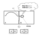
- FIG. 4 illustrates an example of creating a map for self-position estimation in an implementation environment in which rooms A and B with different surrounding environments are connected by a door.
- room A is a fixed room whose layout is not changed
- room B is a room whose layout is frequently changed.
- the mobile device continuously moves (scans) rooms A and B, and creates a self-position estimation map for rooms A and B together.
- the layout of room B is changed, the map of room B needs to be updated.
- the arrow of the room B represents a layout change.
- the map for self-position estimation is created for rooms A and B together, and it is difficult to update only room B. Therefore, it is conceivable that the mobile device moves (scans) only room B again and creates a map for self-position estimation of room B only. In that case, there is a map for self-position estimation that summarizes rooms A and B, and a map for self-position estimation that is only for room B, resulting in maps with overlapping areas, which makes management difficult and wasteful storage. The problem of consuming capacity arises.
- the created map switching determination unit 114 recognizes that the environment has changed, and switches the map. implement. in short.
- a map for self-position estimation of only the room A is created as indicated by the dashed frame in the lower left of FIG.
- a map for self-position estimation of only room B is created as indicated by the dashed frame in the lower right of FIG.
- FIG. 6 shows the case where the implementation environment is a shopping mall 310 .
- this shopping mall 310 there are a shared entrance/event space 311, an aisle 312 in the floor, a store (store A) 313 in the floor, and a store (store B) 314 in the floor.
- the common entrance/event space 311 is large, but the layout changes frequently. Also, the aisle 312 is narrower than the common entrance/event space 311, although the layout remains the same.
- the stores 313 and 314 have a wider space (width) than the aisle 312, the layout is changed for each store, and the color tone of light and decorations are different for each store.
- this shopping mall 310 In the implementation environment of this shopping mall 310, consider a case where the mobile device moves (scans) the shared entrance/event space 311, the aisle 312, the store 313, and the store 314 in that order, and creates a map for self-position estimation.
- the mobile device enters the passage 312 after moving (scanning) the shared entrance/event space 311, for example, the amount of change in the distance to the current surrounding objects due to the difference in the space (width) is
- the threshold value is exceeded, the generated map for self-localization is switched from the map of the common entrance/event space 311 to the map of the passage 312 .
- the current light may The amount of change in color tone becomes larger than the threshold, and the amount of change in the distance to the current surrounding objects becomes larger than the threshold. You can switch to the map of
- the mobile device enters the store 314 after moving (scanning) the store 313, the amount of change in the current light color tone becomes larger than the threshold value due to, for example, the difference in the color tone of the ambient light.
- the generated map for self-position estimation is switched from the map of the store (store A) 313 to the map of the store (store B) 314 .
- maps for self-localization of the shared entrance/event space 311, the aisle 312, the store (store A) 313 and the store (store B) 314 are created separately. Therefore, with respect to the shared entrance/event space 311, the store (store A) 313, and the store (store B) 314, where layout changes are frequent, the mobile device moves (scans) only those areas to change the map for self-position estimation. can be easily done. As a result, there is no need to have a map with overlapping areas, which facilitates management and eliminates wasteful consumption of storage capacity.
- FIG. 7 shows a case where the implementation environment is a road 320 and a parking space 330 adjacent to it.
- a sidewalk 321 exists at the end of the road 320 .
- a sidewalk 321 exists between the road 320 and the parking space 330 .
- the parking space 330 also has a plurality of parking lot management areas, in this example, a parking lot management area (parking lot management area A) 331 and a parking lot management area (parking lot management area B) 332 .
- the mobile device when entering the parking space 330 from the road 320, the mobile device enters the parking space 330 from the main body of the road 320 over the sidewalk 321. In this case, there is a step on the sidewalk 321, and vibration is generated when the step is overcome. Also, the ground colors of the sidewalk 321 and the parking space 330 are different. A narrow space (width) portion 333 exists between the parking lot management area 331 and the parking lot management area 332 .
- the mobile device moves (scans) the road 320, the parking lot management area 331 of the parking space 330, and the parking lot management area 332 of the parking space 330 in order to estimate its own position.
- the mobile device moves (scans) the road 320, the parking lot management area 331 of the parking space 330, and the parking lot management area 332 of the parking space 330 in order to estimate its own position.
- the mobile device after moving (scanning) the road 320, when the mobile device crosses the sidewalk 321 and enters the parking lot management area 331 of the parking space 330, for example, vibration occurs when crossing the sidewalk 321, and the sidewalk Due to the difference in ground color between 321 and the parking lot management area 331, the amount of change in the current amount of vibration is greater than the threshold, and the amount of change in the current light color tone is greater than the threshold. is switched from the map of the road 320 to the map of the parking lot management area 331 .
- the mobile device next time the mobile device enters the parking lot management area 332 after moving (scanning) the parking lot management area 331, it passes through, for example, a narrow space (width). becomes larger than the threshold value, and the generated self-position estimation map is changed from the map of the parking lot management area (parking lot management area A) 331 to the parking lot management area (parking lot management area B) 332 You can switch to the map of
- the self-localization maps of the road 320, the parking lot management area 331 of the parking space 330, and the parking lot management area 332 of the parking space 330 are created separately. . Therefore, when the layout is changed in the parking lot management area 331 or the parking lot management area 332, the mobile device moves (scans) only that area, and the map for self-position estimation can be easily changed. As a result, there is no need to have a map with overlapping areas, which facilitates management and eliminates wasteful consumption of storage capacity.
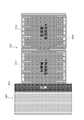
- FIG. 8 shows a case where the implementation environment is a construction site (construction site A) 340, a construction site (construction site B) 350, and a slope 360 connecting them.
- construction site 340 and construction site 350 are in a horizontal plane.
- the color of the ground differs between the slope 360 and the construction sites 340 and 350, and the vibration during movement also differs depending on the structure of the ground. For example, the amount of vibration during movement of construction sites 340 and 350 of sand and gravel construction is greater than that of slope 360 of asphalt construction.
- the moving device enters the slope 360 after moving (scanning) the construction site 340 .
- the map is switched from the map of the construction site (construction site A) 340 to the map of the slope 360 .
- the mobile device enters the construction site 350 after moving (scanning) the slope 360
- the map for estimation is switched from the map of the slope 360 to the map of the construction site (construction site B) 350 .
- the maps for self-position estimation of the construction site 340, the slope 360, and the construction site 350 are created separately. Therefore, with respect to the construction site (construction site A) 340 and the construction site (construction site A) 350 whose layouts are often changed, the mobile device moves (scans) only those areas, thereby facilitating the change of the map for self-position estimation. It can be carried out. As a result, there is no need to have a map with overlapping areas, which facilitates management and eliminates wasteful consumption of storage capacity.
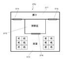
- FIG. 9 shows a case where the implementation environment is the office 370.
- This office 370 has a corridor 371 , living room 372 , and laboratory 373 . Doors 374 and 375 are arranged between the corridor 371 and the living room 372 , and a door 376 is arranged between the living room 372 and the laboratory 373 .
- the corridor 371 is dark and narrow, and the living room 372 is bright.
- the laboratory room 376 has the same brightness as the living room 372, but is narrow. Also, in order to enter the living room 372 from the corridor 371, the moving device needs to be stopped in order to open and close the door 374 or 375. FIG. Also, in order to enter the laboratory 376 from the living room 372 , the moving device must be stopped for opening and closing the door 376 .
- the created map for self-position estimation is switched from the map of the corridor 371 to the map of the room 372 .
- the mobile device stops due to the opening and closing of the door 374 or the door 375. Therefore, the created map for self-position estimation can be obtained from the map of the corridor 371 as follows: It becomes possible to switch to the map of the living room 372 .
- the mobile device enters the laboratory 373 after moving (scanning) the living room 372, for example, due to the difference in space (width), the amount of change in the distance to the current surrounding objects becomes larger than the threshold.
- the created map for self-position estimation is switched from the map of living room 372 to the map of laboratory 373 .
- the mobile device stops due to the opening and closing of the door 376. Therefore, the map for self-position estimation to be created is obtained from the map of the living room 372 and the laboratory room. It is possible to switch to 373 maps.
- maps for self-position estimation of the corridor 371, living room 372, and laboratory 373 are created separately. Therefore, for example, when the layout is changed in the living room 372 or the laboratory 373, the mobile device can move (scan) only that area to easily change the map for self-position estimation. As a result, there is no need to have a map with overlapping areas, which facilitates management and eliminates wasteful consumption of storage capacity.
- FIG. 10 shows a case where the implementation environment is a factory 380.
- This factory 380 has an equipment A area 381 in which equipment A is arranged, an equipment B area 382 in which equipment B is arranged, and a passage 383 connecting these two areas.
- passage 383 is dark and narrow, and areas 381 and 382 are bright and wide.
- the distance to the current surrounding objects may change due to, for example, differences in space (width) and brightness.
- the map for self-position estimation to be created is switched from the map of facility A area 381 to the map of passage 383 .
- the distance to the current surrounding objects may change due to, for example, differences in space (width) and brightness.
- the created self-position estimation map is switched from the map of passage 383 to the map of facility B area 382 .
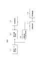
- FIG. 11 shows an example of regions to be divided and sensors used for dividing the regions in each implementation environment.
- the implementation environment is a shopping mall 310 (see FIG. 6), it is divided into areas of a common entrance/event space 311, an aisle 312, a store (store A) 313 and a store (store B) 314, and each self-location An estimation map is created.
- a camera or LiDAR for example, is used as a sensor for recognizing the surrounding environment, which is used for map switching determination.
- the amount of change in the current light color tone is obtained based on the image information obtained by the camera.
- the amount of change in the current distance to the surrounding object is acquired.
- each area of the parking lot management area 331 of the road 320 and the parking space 330 and the parking lot management area 332 of the parking space 330 is divided into two, and each map for self-position estimation is created.
- a camera or a vibration sensor is used as a sensor for recognizing the surrounding environment used for map switching determination.
- the amount of change in the current light color tone is obtained based on the image information obtained by the camera.
- the current amount of change in vibration is acquired based on the output of the vibration sensor.
- the construction site 340, the slope 360, and the construction site 350 are divided into areas, each of which has its own area.
- a position estimation map is created.
- a camera, a vibration sensor, and an inclination sensor are used as sensors for recognizing the surrounding environment used for map switching determination.
- the amount of change in the current light color tone is obtained based on the image information obtained by the camera.
- the current amount of change in vibration is acquired based on the output of the vibration sensor.
- the current amount of change in tilt is acquired based on the output of the tilt sensor.
- the implementation environment is an office 370 (see FIG. 9), it is divided into areas of a corridor 371, living room 372, and laboratory 373, and a map for self-position estimation is created for each area.
- a camera or LiDAR for example, is used as a sensor for recognizing the surrounding environment, which is used for map switching determination.
- the amount of change in the current light color tone is obtained based on the image information obtained by the camera.
- the amount of change in the current distance to the surrounding object is acquired.
- the implementation environment is a factory 380 (see FIG. 10), it is divided into each area of facility A area 381, passage 383, and facility B area 382, and a map for self-position estimation is created for each area.
- a camera or LiDAR for example, is used as a sensor for recognizing the surrounding environment, which is used for map switching determination.
- the amount of change in the current light color tone is obtained based on the image information obtained by the camera.
- the amount of change in the current distance to the surrounding object is acquired.
- the generated map switching determination unit 114 determines the map switching timing further based on the map generation status in the self-position estimation map generation unit 113, for example, as described above.
- the map creation status includes, for example, the amount of map creation.
- the amount of mapping is determined based on the distance traveled by the mobile device to generate the current map.
- the amount of map creation is determined based on the amount of map data currently being created.
- the map creation determination unit 114 determines that it is time to switch maps when the current map creation amount map_ammountga is greater than the map creation amount threshold threshold_map_ammount.
- the map creation status includes, for example, the user's node placement instructions. In this case, locating nodes at locations frequented by mobile devices is performed. This node is a distinct feature point entered by the user.
- the generated map switching determination unit 114 determines that it is time to switch the map when the user instructs node placement.
- the division of the map used in the mobile device is further based on the map creation status. Map switching speed performance, map development performance on memory, etc.) can be created.
- the created map switching determination unit 114 determines the map switching timing further based on, for example, the user's operation.
- the generated map switching determination unit 114 determines that it is map switching timing when a map switching instruction is given by a user operation.
- a map switching instruction by a user operation may be based on a display or utterance (for example, "Would you like to switch the map around here?") prompting the user's instruction in the interaction unit 115.
- a display or utterance for example, "Would you like to switch the map around here?"
- the interaction unit 115 displays or utters an instruction prompting the user.
- the map switching instruction by the user operation may be performed based on the subjectivity of the user.
- the division of the map used in the mobile device is performed further based on the user's intention, and the map can be configured as the user's intention. becomes.
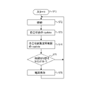
- the flowchart in FIG. 12 outlines the map creation operation by the map creation processing unit 100 shown in FIG. First, the map creation processing unit 100 starts map creation processing in step ST1.
- step ST2 the map creation processing unit 100 moves the position and orientation of the mobile device by a predetermined amount.
- step ST3 the map generation processing unit 100 updates the self-position (position and orientation) based on the estimation result of the self-position estimation unit 112, and in step ST4, converts the map for self-position estimation into a map for self-position estimation. It is updated based on the creation result of the map creation unit 113 .
- step ST5 the map creation processing unit 100 determines whether or not it is time to switch maps in the created map switching determination unit 114 .
- the generated map switching determination unit 114 uses the observation data (surrounding environment recognition result) obtained by the observation data acquisition unit 111, the map generation status in the self-position estimation map generation unit 113, and the user operation. Based on, etc., map switching determination is made.
- step ST5 If it is determined in step ST5 that it is not time to switch maps, the map creation processing section 100 returns to the process of step ST2 and repeats the same process as described above. On the other hand, if it is determined in step ST5 that it is time to switch maps, the map creation processing section 100, in step ST6, treats the maps created by the self-position estimation map creation section 113 as one self-position estimation map. , is stored in the map storage unit 116, and then the process returns to step ST2 to create the next map for self-position estimation.
- map creation processing unit 100 ends the map creation processing automatically or based on a user's operation, for example, after the mobile device has moved (scanned) the entire planned implementation environment area.
- FIG. 13 shows a configuration example of the self-localization processing unit 200 in a self-localization system for a mobile device such as a robot or a car, which is an autonomous mobile body. 13, parts corresponding to those in FIG. 3 are denoted by the same reference numerals, and detailed description thereof will be omitted as appropriate.
- the self-position estimation processing unit 200 estimates the position and orientation using the map for self-position estimation created by the map creation processing unit 100 described above, and controls the movement of the mobile device based on the estimation results.
- Self-position estimation processing unit 200 includes observation data acquisition unit 111, map storage unit 116, self-position estimation unit 201, use map switching determination unit 202, movement control unit 117, and movement mechanism unit 118.
- the observation data acquisition unit 111, the map storage unit 116, the movement control unit 117, and the movement mechanism unit 118 can be used in common in the map creation processing unit 100 described above.
- the map storage unit 116 stores (stores) a map for self-position estimation (for example, a key frame map) created by the map creation processing unit 100 in FIG.
- the self-position estimation unit 201 performs matching processing between the photographed image data obtained by the observation data acquisition unit 111 and a map for self-position estimation (for example, a key frame map) saved (stored) in the map storage unit 116. to estimate the position and pose of the mobile device.
- a map for self-position estimation for example, a key frame map
- the use map switching determination unit 202 performs map switching determination based on the observation data (surrounding environment recognition results) obtained by the observation data acquisition unit 111 . Note that the created map switching determination unit 114 shown in FIG. However, here, the map switching determination is performed based only on the observation data (surrounding environment recognition result) obtained by the observation data acquisition unit 111 .
- the use map switching determination unit 202 refers to the map switching determination result indicating that it is time to switch, and based on the position estimation result estimated by the self-position estimation unit 201, the map storage unit 116 stores the The self-position estimation map of the region to be used by the self-position estimation unit 201 is read from among the stored self-position estimation maps of a plurality of regions, and supplied to the self-position estimation unit 201 . As a result, the map for self-position estimation used by the self-position estimation unit 201 is sequentially updated to an appropriate map according to the movement position of the mobile device.
- Movement control section 117 controls the movement of the mobile device based on the position and orientation estimated by self-position estimation section 201 .
- the direction, distance, speed, and the like to be moved are calculated from the position, posture, and route information, and the movement mechanism 118 is controlled based on the results.
- FIG. 14 is a block diagram showing a hardware configuration example of a computer 400 that executes the series of processes described above by a program.
- CPU Central Processing Unit
- ROM Read Only Memory
- RAM Random Access Memory
- An input/output interface 405 is further connected to the bus 404 .
- An input unit 406 , an output unit 407 , a recording unit 408 , a communication unit 409 and a drive 410 are connected to the input/output interface 405 .
- the input unit 406 consists of input switches, buttons, a microphone, an imaging device, and the like.
- the output unit 407 includes a display, a speaker, and the like.
- a recording unit 408 is composed of a hard disk, a nonvolatile memory, or the like.
- a communication unit 409 includes a network interface and the like.
- a drive 410 drives a removable recording medium 411 such as a magnetic disk, optical disk, magneto-optical disk, or semiconductor memory.
- the CPU 401 loads, for example, a program recorded in the recording unit 408 into the RAM 403 via the input/output interface 405 and the bus 404 and executes the above-described A series of processes are performed.
- a program executed by the computer 400 can be provided by being recorded on a removable recording medium 411 such as a package medium, for example. Also, the program can be provided via a wired or wireless transmission medium such as a local area network, the Internet, or digital satellite broadcasting.
- the program can be installed in the recording unit 408 via the input/output interface 405 by loading the removable recording medium 411 into the drive 410 . Also, the program can be received by the communication unit 409 and installed in the recording unit 408 via a wired or wireless transmission medium. In addition, programs can be installed in the ROM 402 and the recording unit 408 in advance.
- the program executed by the computer may be a program in which processing is performed in chronological order according to the order described in this specification, or in parallel or at a necessary timing such as when a call is made. It may be a program in which processing is performed.
- a system means a set of multiple components (devices, modules (parts), etc.), and it does not matter whether all the components are in the same housing. Therefore, a plurality of devices housed in separate housings and connected via a network, and a single device housing a plurality of modules in one housing, are both systems. .
- this technology can take the configuration of cloud computing in which one function is shared by multiple devices via a network and processed jointly.
- each step described in the flowchart above can be executed by a single device, or can be shared by a plurality of devices.
- the multiple processes included in the one step can be executed by one device or shared by multiple devices.
- the map creation processing unit 100 determines map switching (end of creation of the first map and start of creation of the second map) based on the recognition result of the surrounding environment. Based on the results, multiple implementation environments are divided into multiple regions, and a map of each region is created. Therefore, the division of the map used in the mobile device is performed based on the surrounding environment, so that management and updating can be performed well.
- the map creation processing unit 100 determines map switching (end of creation of the first map and start of creation of the second map) further based on the map creation status. Based on this, multiple implementation environments are divided into multiple regions and a map of each region is created. Therefore, for example, it is possible to create a map having a size that matches the performance of the mobile device (map switching speed performance, map development performance on memory, etc.).
- the map creation processing unit 100 determines map switching (end of creation of the first map and start of creation of the second map) further based on the user operation, and based on the result , multiple implementation environments are divided into multiple regions, and a map of each region is created. Therefore, the division of the map used in the mobile device is performed based on the user's intention, and the map configuration can be made as the user's intention.
- this technique can also take the following structures.
- a map creation unit that creates at least a first map and a second map based on a first recognition result of the surrounding environment; an information processing apparatus, comprising: a created map switching determination unit that determines termination of creation of the first map and start of creation of the second map based on a second recognition result of the surrounding environment.
- the information processing apparatus according to (1) wherein the first map and the second map are maps of adjacent areas.
- each of the first map and the second map is a map whose range is an area having similar environmental information.
- the map created by the map creation unit is a map for self-position estimation.
- the information processing apparatus determines whether to end creation of the first map and start creation of the second map, further based on the map creation status in the map creation unit. ) to (8).
- the information processing apparatus according to (9), wherein the map creation status includes the map creation amount.
- the information processing device according to (10), wherein the map creation amount is determined based on the distance traveled by the mobile device including the information processing device to create the current map.
- the amount of map creation is determined based on the amount of map data currently being created.
- the information processing apparatus according to (9), wherein the map creation status includes a node placement instruction by a user.
- the created map switching determination unit determines, further based on a user operation, to end creation of the first map and start creation of the second map. 1.
- a map holding unit holding a plurality of maps including at least the first map and the second map; a use map switching determination unit that switches between the plurality of maps based on a change in the surrounding environment;
- the information processing apparatus according to any one of (1) to (14), further comprising a self-position estimation unit that estimates the self-position based on the map being used.
- a mapping procedure for generating at least a first map and a second map based on the first recognition result of the surrounding environment; an information processing method, comprising: a created map switching determination procedure for determining the end of creation of the first map and the start of creation of the second map based on a second recognition result of the surrounding environment.
- a computer a mapping unit that generates at least a first map and a second map based on the first recognition result of the surrounding environment;
- a mobile device comprising an information processing device, The information processing device is a mapping unit that generates at least a first map and a second map based on the first recognition result of the surrounding environment; a created map switching determination unit that determines termination of creation of the first map and start of creation of the second map based on a second recognition result of the surrounding environment.
Landscapes
- Engineering & Computer Science (AREA)
- Radar, Positioning & Navigation (AREA)
- Physics & Mathematics (AREA)
- Remote Sensing (AREA)
- General Physics & Mathematics (AREA)
- Automation & Control Theory (AREA)
- Theoretical Computer Science (AREA)
- Aviation & Aerospace Engineering (AREA)
- Business, Economics & Management (AREA)
- Educational Technology (AREA)
- Educational Administration (AREA)
- Mathematical Physics (AREA)
- Databases & Information Systems (AREA)
- Instructional Devices (AREA)
- Control Of Position, Course, Altitude, Or Attitude Of Moving Bodies (AREA)
- Navigation (AREA)
- Traffic Control Systems (AREA)
Abstract
La présente invention permet de créer favorablement une carte à utiliser dans un dispositif mobile. Au moins une première carte et une seconde carte sont créées sur la base d'un premier résultat de reconnaissance sur l'environnement ambiant. Une unité de détermination de commutation de création de carte détermine, sur la base d'un second résultat de reconnaissance sur l'environnement ambiant, l'achèvement de création de la première carte et le début de création de la seconde carte. Une carte à utiliser dans un dispositif mobile est divisée sur la base de l'environnement ambiant, et ainsi la gestion/mise à jour peut être réalisée favorablement. Par exemple, l'unité de détermination de commutation de création de carte peut déterminer l'achèvement de création de la première carte et le début de création de la seconde carte sur la base, en outre, d'une situation de création de carte dans l'unité de création de carte, ou d'une opération de l'utilisateur.
Priority Applications (1)
| Application Number | Priority Date | Filing Date | Title |
|---|---|---|---|
| US18/261,333 US20240069564A1 (en) | 2021-01-22 | 2021-12-16 | Information processing device, information processing method, program, and mobile apparatus |
Applications Claiming Priority (2)
| Application Number | Priority Date | Filing Date | Title |
|---|---|---|---|
| JP2021-009160 | 2021-01-22 | ||
| JP2021009160A JP2022113054A (ja) | 2021-01-22 | 2021-01-22 | 情報処理装置、情報処理方法、プログラムおよび移動装置 |
Publications (1)
| Publication Number | Publication Date |
|---|---|
| WO2022158185A1 true WO2022158185A1 (fr) | 2022-07-28 |
Family
ID=82548201
Family Applications (1)
| Application Number | Title | Priority Date | Filing Date |
|---|---|---|---|
| PCT/JP2021/046500 WO2022158185A1 (fr) | 2021-01-22 | 2021-12-16 | Dispositif de traitement d'informations, procédé de traitement d'informations, programme et dispositif mobile |
Country Status (3)
| Country | Link |
|---|---|
| US (1) | US20240069564A1 (fr) |
| JP (1) | JP2022113054A (fr) |
| WO (1) | WO2022158185A1 (fr) |
Families Citing this family (2)
| Publication number | Priority date | Publication date | Assignee | Title |
|---|---|---|---|---|
| WO2024053145A1 (fr) * | 2022-09-07 | 2024-03-14 | ソニーグループ株式会社 | Dispositif de traitement d'informations, procédé de traitement d'informations et programme |
| CN117948969A (zh) * | 2022-10-31 | 2024-04-30 | 沃尔沃汽车公司 | 用于车辆定位的方法、设备、系统和计算机可读存储介质 |
Citations (3)
| Publication number | Priority date | Publication date | Assignee | Title |
|---|---|---|---|---|
| EP3184013A1 (fr) * | 2014-08-20 | 2017-06-28 | Samsung Electronics Co., Ltd | Robot de nettoyage et son procédé de commande |
| WO2020226085A1 (fr) * | 2019-05-09 | 2020-11-12 | ソニー株式会社 | Dispositif de traitement d'informations, procédé de traitement d'informations et programme |
| JP2020533720A (ja) * | 2017-09-12 | 2020-11-19 | ロブアート ゲーエムベーハーROBART GmbH | 自律移動ロボットによる未知の環境の探索 |
-
2021
- 2021-01-22 JP JP2021009160A patent/JP2022113054A/ja active Pending
- 2021-12-16 WO PCT/JP2021/046500 patent/WO2022158185A1/fr active Application Filing
- 2021-12-16 US US18/261,333 patent/US20240069564A1/en active Pending
Patent Citations (3)
| Publication number | Priority date | Publication date | Assignee | Title |
|---|---|---|---|---|
| EP3184013A1 (fr) * | 2014-08-20 | 2017-06-28 | Samsung Electronics Co., Ltd | Robot de nettoyage et son procédé de commande |
| JP2020533720A (ja) * | 2017-09-12 | 2020-11-19 | ロブアート ゲーエムベーハーROBART GmbH | 自律移動ロボットによる未知の環境の探索 |
| WO2020226085A1 (fr) * | 2019-05-09 | 2020-11-12 | ソニー株式会社 | Dispositif de traitement d'informations, procédé de traitement d'informations et programme |
Also Published As
| Publication number | Publication date |
|---|---|
| JP2022113054A (ja) | 2022-08-03 |
| US20240069564A1 (en) | 2024-02-29 |
Similar Documents
| Publication | Publication Date | Title |
|---|---|---|
| JP7257737B2 (ja) | 情報処理装置、自己位置推定方法、及び、プログラム | |
| US20230230368A1 (en) | Information processing apparatus, information processing method, and program | |
| WO2022158185A1 (fr) | Dispositif de traitement d'informations, procédé de traitement d'informations, programme et dispositif mobile | |
| CN112534297A (zh) | 信息处理设备和信息处理方法、计算机程序、信息处理系统以及移动设备 | |
| WO2021060018A1 (fr) | Dispositif de traitement de signal, procédé de traitement de signal, programme et dispositif mobile | |
| US20240054793A1 (en) | Information processing device, information processing method, and program | |
| WO2020241303A1 (fr) | Dispositif de commande de déplacement autonome, système de commande de déplacement autonome et procédé de commande de déplacement autonome | |
| US20220277556A1 (en) | Information processing device, information processing method, and program | |
| WO2023153083A1 (fr) | Dispositif de traitement d'informations, procédé de traitement d'informations, programme de traitement d'informations et dispositif de déplacement | |
| US20230289980A1 (en) | Learning model generation method, information processing device, and information processing system | |
| WO2022004448A1 (fr) | Dispositif de traitement d'informations, procédé de traitement d'informations, système de traitement d'informations et programme | |
| WO2023074419A1 (fr) | Dispositif de traitement d'information, procédé de traitement d'information et système de traitement d'information | |
| WO2023063145A1 (fr) | Dispositif de traitement d'informations, procédé de traitement d'informations et programme de traitement d'informations | |
| WO2024024471A1 (fr) | Dispositif de traitement d'informations, procédé de traitement d'informations et système de traitement d'informations | |
| WO2023054090A1 (fr) | Dispositif de traitement de reconnaissance, procédé de traitement de reconnaissance et système de traitement de reconnaissance | |
| US20230267746A1 (en) | Information processing device, information processing method, and program | |
| WO2023053498A1 (fr) | Dispositif de traitement d'informations, procédé de traitement d'informations, support d'enregistrement et système embarqué | |
| WO2023007785A1 (fr) | Dispositif de traitement d'informations, procédé de traitement d'informations et programme | |
| WO2023149089A1 (fr) | Dispositif d'apprentissage, procédé d'apprentissage, et programme d'apprentissage | |
| WO2023171401A1 (fr) | Dispositif de traitement de signal, procédé de traitement de signal et support d'enregistrement | |
| US20230206596A1 (en) | Information processing device, information processing method, and program | |
| WO2022024569A1 (fr) | Dispositif et procédé de traitement d'informations, et programme | |
| WO2022259621A1 (fr) | Dispositif de traitement d'informations, procédé de traitement d'informations et programme informatique | |
| WO2024062976A1 (fr) | Dispositif et procédé de traitement d'informations | |
| WO2023145529A1 (fr) | Dispositif, procédé et programme de traitement d'informations |
Legal Events
| Date | Code | Title | Description |
|---|---|---|---|
| 121 | Ep: the epo has been informed by wipo that ep was designated in this application |
Ref document number: 21921287 Country of ref document: EP Kind code of ref document: A1 |
|
| WWE | Wipo information: entry into national phase |
Ref document number: 18261333 Country of ref document: US |
|
| NENP | Non-entry into the national phase |
Ref country code: DE |
|
| 122 | Ep: pct application non-entry in european phase |
Ref document number: 21921287 Country of ref document: EP Kind code of ref document: A1 |