WO2022153653A1 - 測距システム - Google Patents
測距システム Download PDFInfo
- Publication number
- WO2022153653A1 WO2022153653A1 PCT/JP2021/041251 JP2021041251W WO2022153653A1 WO 2022153653 A1 WO2022153653 A1 WO 2022153653A1 JP 2021041251 W JP2021041251 W JP 2021041251W WO 2022153653 A1 WO2022153653 A1 WO 2022153653A1
- Authority
- WO
- WIPO (PCT)
- Prior art keywords
- processing circuit
- blank area
- storage device
- point cloud
- blank
- Prior art date
- Legal status (The legal status is an assumption and is not a legal conclusion. Google has not performed a legal analysis and makes no representation as to the accuracy of the status listed.)
- Ceased
Links
Images



























Classifications
-
- G—PHYSICS
- G01—MEASURING; TESTING
- G01S—RADIO DIRECTION-FINDING; RADIO NAVIGATION; DETERMINING DISTANCE OR VELOCITY BY USE OF RADIO WAVES; LOCATING OR PRESENCE-DETECTING BY USE OF THE REFLECTION OR RERADIATION OF RADIO WAVES; ANALOGOUS ARRANGEMENTS USING OTHER WAVES
- G01S17/00—Systems using the reflection or reradiation of electromagnetic waves other than radio waves, e.g. lidar systems
- G01S17/88—Lidar systems specially adapted for specific applications
- G01S17/93—Lidar systems specially adapted for specific applications for anti-collision purposes
- G01S17/931—Lidar systems specially adapted for specific applications for anti-collision purposes of land vehicles
-
- G—PHYSICS
- G01—MEASURING; TESTING
- G01S—RADIO DIRECTION-FINDING; RADIO NAVIGATION; DETERMINING DISTANCE OR VELOCITY BY USE OF RADIO WAVES; LOCATING OR PRESENCE-DETECTING BY USE OF THE REFLECTION OR RERADIATION OF RADIO WAVES; ANALOGOUS ARRANGEMENTS USING OTHER WAVES
- G01S17/00—Systems using the reflection or reradiation of electromagnetic waves other than radio waves, e.g. lidar systems
- G01S17/88—Lidar systems specially adapted for specific applications
- G01S17/89—Lidar systems specially adapted for specific applications for mapping or imaging
- G01S17/894—Three-dimensional [3D] imaging with simultaneous measurement of time-of-flight at a two-dimensional [2D] array of receiver pixels, e.g. time-of-flight cameras or flash lidar
-
- G—PHYSICS
- G01—MEASURING; TESTING
- G01S—RADIO DIRECTION-FINDING; RADIO NAVIGATION; DETERMINING DISTANCE OR VELOCITY BY USE OF RADIO WAVES; LOCATING OR PRESENCE-DETECTING BY USE OF THE REFLECTION OR RERADIATION OF RADIO WAVES; ANALOGOUS ARRANGEMENTS USING OTHER WAVES
- G01S17/00—Systems using the reflection or reradiation of electromagnetic waves other than radio waves, e.g. lidar systems
- G01S17/02—Systems using the reflection of electromagnetic waves other than radio waves
- G01S17/06—Systems determining position data of a target
- G01S17/08—Systems determining position data of a target for measuring distance only
- G01S17/10—Systems determining position data of a target for measuring distance only using transmission of interrupted, pulse-modulated waves
-
- G—PHYSICS
- G01—MEASURING; TESTING
- G01S—RADIO DIRECTION-FINDING; RADIO NAVIGATION; DETERMINING DISTANCE OR VELOCITY BY USE OF RADIO WAVES; LOCATING OR PRESENCE-DETECTING BY USE OF THE REFLECTION OR RERADIATION OF RADIO WAVES; ANALOGOUS ARRANGEMENTS USING OTHER WAVES
- G01S17/00—Systems using the reflection or reradiation of electromagnetic waves other than radio waves, e.g. lidar systems
- G01S17/86—Combinations of lidar systems with systems other than lidar, radar or sonar, e.g. with direction finders
-
- G—PHYSICS
- G01—MEASURING; TESTING
- G01S—RADIO DIRECTION-FINDING; RADIO NAVIGATION; DETERMINING DISTANCE OR VELOCITY BY USE OF RADIO WAVES; LOCATING OR PRESENCE-DETECTING BY USE OF THE REFLECTION OR RERADIATION OF RADIO WAVES; ANALOGOUS ARRANGEMENTS USING OTHER WAVES
- G01S17/00—Systems using the reflection or reradiation of electromagnetic waves other than radio waves, e.g. lidar systems
- G01S17/88—Lidar systems specially adapted for specific applications
- G01S17/89—Lidar systems specially adapted for specific applications for mapping or imaging
-
- G—PHYSICS
- G01—MEASURING; TESTING
- G01S—RADIO DIRECTION-FINDING; RADIO NAVIGATION; DETERMINING DISTANCE OR VELOCITY BY USE OF RADIO WAVES; LOCATING OR PRESENCE-DETECTING BY USE OF THE REFLECTION OR RERADIATION OF RADIO WAVES; ANALOGOUS ARRANGEMENTS USING OTHER WAVES
- G01S7/00—Details of systems according to groups G01S13/00, G01S15/00, G01S17/00
- G01S7/48—Details of systems according to groups G01S13/00, G01S15/00, G01S17/00 of systems according to group G01S17/00
- G01S7/4808—Evaluating distance, position or velocity data
-
- G—PHYSICS
- G01—MEASURING; TESTING
- G01S—RADIO DIRECTION-FINDING; RADIO NAVIGATION; DETERMINING DISTANCE OR VELOCITY BY USE OF RADIO WAVES; LOCATING OR PRESENCE-DETECTING BY USE OF THE REFLECTION OR RERADIATION OF RADIO WAVES; ANALOGOUS ARRANGEMENTS USING OTHER WAVES
- G01S7/00—Details of systems according to groups G01S13/00, G01S15/00, G01S17/00
- G01S7/48—Details of systems according to groups G01S13/00, G01S15/00, G01S17/00 of systems according to group G01S17/00
- G01S7/481—Constructional features, e.g. arrangements of optical elements
- G01S7/4817—Constructional features, e.g. arrangements of optical elements relating to scanning
-
- G—PHYSICS
- G01—MEASURING; TESTING
- G01S—RADIO DIRECTION-FINDING; RADIO NAVIGATION; DETERMINING DISTANCE OR VELOCITY BY USE OF RADIO WAVES; LOCATING OR PRESENCE-DETECTING BY USE OF THE REFLECTION OR RERADIATION OF RADIO WAVES; ANALOGOUS ARRANGEMENTS USING OTHER WAVES
- G01S7/00—Details of systems according to groups G01S13/00, G01S15/00, G01S17/00
- G01S7/48—Details of systems according to groups G01S13/00, G01S15/00, G01S17/00 of systems according to group G01S17/00
- G01S7/483—Details of pulse systems
- G01S7/486—Receivers
- G01S7/4865—Time delay measurement, e.g. time-of-flight measurement, time of arrival measurement or determining the exact position of a peak
-
- G—PHYSICS
- G06—COMPUTING OR CALCULATING; COUNTING
- G06T—IMAGE DATA PROCESSING OR GENERATION, IN GENERAL
- G06T7/00—Image analysis
- G06T7/50—Depth or shape recovery
- G06T7/55—Depth or shape recovery from multiple images
- G06T7/564—Depth or shape recovery from multiple images from contours
-
- G—PHYSICS
- G06—COMPUTING OR CALCULATING; COUNTING
- G06T—IMAGE DATA PROCESSING OR GENERATION, IN GENERAL
- G06T7/00—Image analysis
- G06T7/50—Depth or shape recovery
- G06T7/55—Depth or shape recovery from multiple images
- G06T7/593—Depth or shape recovery from multiple images from stereo images
-
- G—PHYSICS
- G06—COMPUTING OR CALCULATING; COUNTING
- G06V—IMAGE OR VIDEO RECOGNITION OR UNDERSTANDING
- G06V20/00—Scenes; Scene-specific elements
- G06V20/50—Context or environment of the image
- G06V20/56—Context or environment of the image exterior to a vehicle by using sensors mounted on the vehicle
-
- G—PHYSICS
- G06—COMPUTING OR CALCULATING; COUNTING
- G06T—IMAGE DATA PROCESSING OR GENERATION, IN GENERAL
- G06T2207/00—Indexing scheme for image analysis or image enhancement
- G06T2207/10—Image acquisition modality
- G06T2207/10028—Range image; Depth image; 3D point clouds
Definitions
- This disclosure relates to a rangefinder system.
- Patent Document 1 discloses a system that complements the depth information in the first depth map generated by the first camera based on the depth information in the second depth map generated by the second camera. ..
- the system of Patent Document 1 complements the depth value of an empty pixel lacking depth information in the first depth map based on the depth value of the corresponding pixel in the second depth map.
- the system generates a 3D model (eg, a point cloud) of an object based on a first depth map complemented by the depth values of empty pixels.
- One aspect of the present disclosure provides a novel sensing method for selectively measuring a region in which data could not be obtained by another range finder in a system including a plurality of range finder.
- the LiDAR sensor is based on a plurality of rangefinders including the LiDAR sensor and one or more other rangefinders, and rangefinder data acquired by each of the plurality of rangefinders. It is used in a rangefinder system including a storage device for storing dimensional point group data.
- the LiDAR sensor includes a light emitting device capable of changing the emission direction of a light beam, a light receiving device that detects reflected light by the light beam and outputs a signal indicating a detection result, the light emitting device, and the light receiving device.
- a processing circuit that controls the above and generates the distance measurement data based on the signal output from the light receiving device.
- the processing circuit refers to the point cloud data, determines one or more blank areas of the point cloud data, and causes the light emitting device to emit the light beam toward the blank area, thereby causing the blank area. Measure the distance of the area.
- the present disclosure may be implemented by recording media such as systems, devices, methods, integrated circuits, computer programs or computer readable recording disks, systems, devices, methods, integrated circuits, etc. It may be realized by any combination of a computer program and a recording medium.
- the computer-readable recording medium may include a volatile recording medium, or may include a non-volatile recording medium such as a CD-ROM (Compact Disc-Read Only Memory).
- the device may consist of one or more devices. When the device is composed of two or more devices, the two or more devices may be arranged in one device, or may be separately arranged in two or more separated devices.
- "device" can mean not only one device, but also a system of multiple devices.
- FIG. It is a block diagram which shows typically the configuration example of the system which controls a moving body in Embodiment 1.
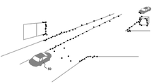
- FIG. It is a top view which shows typically the example of the vehicle which includes a plurality of rangefinders. It is a figure which shows an example of the structure of a beam scanner and a light receiving device. It is a figure which shows the other configuration example of a beam scanner. It is a figure which shows the other structural example of a beam scanner. It is a figure which shows the example of the schematic operation of a range finder system. It is a bird's-eye view which shows typically the example of the point cloud whose distance was measured by a range finder. It is a figure for demonstrating the three-dimensional coordinate system used in Embodiment 1.
- FIG. It is a top view which shows typically the example of the vehicle which includes a plurality of rangefinders. It is a figure which shows an example of the structure of a beam scanner and a light receiving device. It is a figure which shows the other configuration example of
- step S8700 shows the detail of the distance measurement operation of step S8700 shown in FIG. It is the first figure for demonstrating the three-dimensional measurement method of the edge part with respect to the left camera in a stereo camera. It is a 2nd figure for demonstrating the 3D measurement method of the edge part with respect to the left camera in a stereo camera. It is a 3rd figure for demonstrating the 3D measurement method of the edge part with respect to the left camera in a stereo camera.
- all or part of a circuit, unit, device, member or part, or all or part of a functional block in a block diagram is, for example, a semiconductor device, a semiconductor integrated circuit (IC), or an LSI (range scale integration). ) Can be performed by one or more electronic circuits.
- the LSI or IC may be integrated on one chip, or may be configured by combining a plurality of chips.
- functional blocks other than the storage element may be integrated on one chip.
- it is called LSI or IC, but the name changes depending on the degree of integration, and it may be called system LSI, VLSI (very large scale integration), or ULSI (ultra large scale integration).
- Field Programmable Gate Array (FPGA) which is programmed after the LSI is manufactured, or reconfigurable logistic device, which can reconfigure the junction relationship inside the LSI or set up the circuit partition inside the LSI, can also be used for the same purpose.
- FPGA Field Programmable Gate Array
- the LiDAR sensor selectively measures a blank area for which rangefinder data could not be obtained by another rangefinder. As a result, more distance data can be efficiently acquired in a system including a plurality of rangefinders.
- the processing circuit determines a plurality of blank areas of the point cloud data, sets a priority order for the plurality of blank areas, and directs the light beam to the light emitting device in the direction of each blank area according to the set priority order.
- the distance measurement of the plurality of blank areas may be performed in order by emitting the light in order toward.
- the processing circuit acquires map data including position information of the structure and matches the map data with the point cloud data to correspond to the position of a specific structure from the plurality of blank areas.
- One or more blank areas may be extracted, and the priority of the extracted blank areas may be higher than the priority of other blank areas.
- the processing circuit may execute the determination of the blank area and the distance measurement of the blank area when the point cloud data in the storage device is updated.
- the processing circuit executes the determination of the blank area and / or the distance measurement of the blank area. You may try again.
- the storage device may be updated by converting the coordinates of the point cloud data when the position and / or posture of the distance measuring system changes.
- the processing circuit is updated by the storage device by performing coordinate conversion of the point cloud data, the priority of the plurality of blank areas may be reset.
- each component in the range finder system 100 will be described in more detail.
- the beam scanner 111 is a light emitting device capable of changing the emission direction of the light beam.
- the beam scanner 111 includes one or more light sources and emits a light beam in a direction indicated by the processing circuit 113.
- the configuration of the beam scanner 111 will be described.
- FIG. 3 is a diagram showing an example of the configuration of the beam scanner 111 and the light receiving device 112.
- the beam scanner 111 in this example includes a light source 22 and an actuator 24.
- the actuator 24 includes a movable mirror 26.
- the beam scanner 111 can rotate the movable mirror 26 by the action of the actuator 24 to change the emission direction of the light beam.
- the light source 22 is, for example, a laser light source and emits a laser beam.
- the spot shape of the laser beam may be a shape close to a circle or a line shape.
- the light source 22 may include a semiconductor laser element and a lens that collimates a laser beam emitted from the semiconductor laser element.
- the wavelength of the laser beam emitted from the light source 22 may be, for example, a wavelength included in the near-infrared wavelength region (approximately 700 nm to 2.5 ⁇ m).
- the wavelength used depends on the material of the photoelectric conversion element used in the light receiving device 112. For example, when silicon (Si) is used as a material for a photoelectric conversion element, a wavelength of around 900 nm can be mainly used.
- Si silicon
- InGaAs indium gallium arsenide
- a wavelength of 1000 nm or more and 1650 nm or less can be used.
- the wavelength of the laser beam is not limited to the near infrared wavelength range.
- the actuator 24 in the example shown in FIG. 3 includes a plurality of motors 25, a mirror 26 connected to the motors 25 and rotated, and a half mirror 27.
- the mirror 26 can be rotated around two axes by two motors 25.
- the half mirror 27 is arranged on the optical path of the laser beam emitted from the light source 22, reflects the laser beam, and is incident on the mirror 26.
- the laser beam reflected by the mirror 26 irradiates the object 30 as a light beam 60.
- the light beam 60 reflected by the object 30 returns to the mirror 26 as reflected light 70, is reflected, and heads toward the half mirror 27.
- the half mirror 27 transmits the reflected light 70 reflected by the mirror 26 and causes it to enter the light receiving device 112.
- the actuator 24 changes the angle of the mirror 26 in response to the control signal input from the processing circuit 113. As a result, the emission direction of the light beam 60 can be changed within a predetermined range.
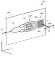
- the beam scanner 111 is an optical device capable of changing the emission direction of the light beam without providing a mechanical moving part such as an optical scanning device having a slow light structure or a phased array instead of the actuator 24. May be provided. Since the optical device that does not include the mechanical moving part is not affected by inertia, there is an advantage that the influence when vibration occurs can be reduced.
- Each phase shifter 220 includes an optical waveguide extending in the X direction.
- the plurality of optical waveguide elements 280 in the optical waveguide array 280A are connected to the plurality of phase shifters 220 in the phase shifter array 220A, respectively.
- An optical turnout 230 is connected to the phase shifter array 220A.
- the refractive index of the liquid crystal layer changes, and the direction of the light emitted from the optical waveguide element 280 to the outside changes.
- the direction of the light beam 60 emitted from the optical waveguide array 280A can be changed along the direction D1 parallel to the X-axis according to the change in voltage.
- Each phase shifter 220 includes, for example, a total reflection waveguide containing a thermooptical material whose refractive index changes with heat, a heater that is in thermal contact with the total reflection waveguide, and a pair of electrodes for applying a drive voltage to the heater. And include.
- the light input to the total reflection waveguide propagates along the X direction while being totally reflected in the total reflection waveguide.
- the pair of electrodes By applying a voltage to the pair of electrodes, the total internal reflection waveguide is heated by the heater.
- the refractive index of the total reflection waveguide changes, and the phase of the light output from the end of the total reflection waveguide changes.
- the emission direction of the light beam 60 can be changed along the direction D2 parallel to the Y axis.
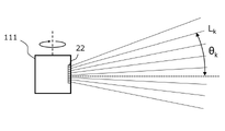
- FIG. 5 is a diagram schematically showing an example of a beam scanner 111 including a plurality of laser light sources 22 arranged in the vertical direction.
- the radially extending straight lines shown in FIG. 5 schematically represent the central axis of the laser beam emitted from each light source 22. In the figure, for simplicity, the spread of the laser beam is ignored and only the central axis of the laser beam is shown.
- laser beams are emitted from a plurality of laser light sources 22 arranged in the vertical direction at different elevation angles.
- FIG. 5 shows, as an example, the elevation angle ⁇ k of the k-th laser beam L k .
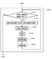
- FIG. 10 is a flowchart showing an outline of the operation of the LiDAR sensor 110.
- the LiDAR sensor 110 receives a signal instructing the start of the operation from the control circuit 160, the LiDAR sensor 110 executes the operations of steps S1100 to S1600 shown in FIG. The operation of each step will be described below.
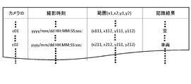
- Step S1425 The processing circuit 113 records the block as an extraction block in the storage device 114.
- the recorded information is, for example, the same as the information shown in FIG. That is, the block ID, the extraction time, and the block range can be recorded in the storage device 114. After step S1425, the process returns to step S1421.
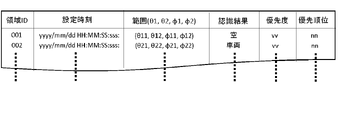
- the processing circuit 113 weights each of the one or more blank areas recorded in the storage device 114 by the azimuth angle, the polar angle, and the size of the area at the coordinates of the point cloud data 131, and based on those weights. And calculate the priority.
- the processing circuit 113 compares the priorities of one or more blank areas recorded in the storage device 114, prioritizes them in descending order of priority, and records the information in the storage device 114.
- Step S2411> The processing circuit 113 determines whether or not the priority has been calculated for all of the one or more blank areas recorded in the storage device 114 in step S1470. When the calculation of the priority of all the blank areas is completed, the process proceeds to step S2420. If there is a blank area for which the priority has not yet been calculated, the process proceeds to step S2412.
- the processing circuit 113 obtains the weight ⁇ b corresponding to the number of blocks integrated by the iterative processing of steps S1430 to S1470. For example, the larger the number of blocks, the larger the weight ⁇ b is set.
- the weight ⁇ b may be, for example, the number of blocks itself.
- FIG. 19 is a flowchart showing the details of the distance measuring operation in the blank area of the LiDAR sensor 110 according to the second embodiment.
- the operation shown in FIG. 19 is the same as the operation shown in FIG. 13 except that step S1520 in the operation of the first embodiment shown in FIG. 13 is replaced with step S2520.
- the image recognition device 170 includes an image recognition circuit 171 and a storage device 172.
- the image recognition circuit 171 includes a processor such as a GPU and is connected to the image processing circuit 123 in the stereo camera 120.
- the image recognition circuit 171 acquires an image taken by the left camera 121 or the right camera 122 of the stereo camera 120, and recognizes a specific object such as a structure or a moving body in the image.
- a known image recognition algorithm can be used for recognition.
- a machine learning algorithm can be used to recognize a particular object from an image based on a pre-trained trained model.
- the recognized object can be any object that exists around the moving object, such as a pedestrian, a vehicle, a building, a road, the sky, or a mountain.
- the image recognition circuit 171 acquires an image of a monocular camera having a range-finding function, and recognizes a specific object such as a structure or a moving body in the image.
- a monocular camera having a range-finding function estimates a distance by using, for example, the blurring of the edge of an object in an image.
- the monocular camera having a range-finding function stores the points on the edge whose distance can be estimated as point cloud data in the storage device 130.
- FIG. 22 is a flowchart showing the operation of the LiDAR sensor 110 in this modified example.
- step S1400 in the flowchart shown in FIG. 10 is replaced with steps S2100, S2200, and S2300.
- the operations of steps S1100 to S1300, S1500, and S1600 are the same as the operations of the corresponding steps shown in FIG.
- an operation different from the operation shown in FIG. 10 will be described.
- the processing circuit 113 acquires the recognition result of the latest image from the storage device 172 of the image recognition device 170.
- the LiDAR sensor 110 may select a camera whose imaging range overlaps with the scanning range of the beam scanner 111, and acquire only the image recognition result by the camera.
- Step S2300 The processing circuit 113 extracts one or more blank areas with reference to the point cloud data 131 recorded in the storage device 130, determines the priority of distance measurement, and records the information in the storage device 114.
- the recognition result acquired in step S2100 is used for extracting the blank area and determining the priority. Details of the method of extracting the blank area and determining the priority will be described later with reference to FIG. 23.
- Step S2330> The processing circuit 113 combines the blocks with all other extraction blocks that overlap a single recognition target range and integrates them as one region. By this process, a plurality of blocks overlapping a single recognition target range can be combined as one continuous region. In this modified example, unlike step S1460 in the examples shown in FIGS. 11 and 14, the combination process is not performed on the low-frequency blocks that do not overlap with any recognition target range.
- step S1470 the processing circuit 113 records the blank area and the recognition target in the storage device 114 in association with each other. Blank areas that do not have a recognition target are recorded without being associated with the recognition target.
- a blank area is set based on the result of image recognition, and the priority of distance measurement is determined.
- the distance in the blank area where an important object is likely to be overlooked, instead of the distant view such as the sky which is often included in the blank area.
- more accurate point cloud data can be generated.
- the map acquisition device 180 includes a receiving device 181 and a matching device 182.
- the receiving device 181 wirelessly communicates with an external device of the system 10.
- the receiving device 181 receives the map information distributed via the external network. Distribution by an external network can be, for example, a road map distribution network in a navigation system.
- the map information can be, for example, a road map.
- the receiving device 181 acquires map information around the current position specified by a positioning device such as a GPS receiver included in the moving body on which the system 10 is mounted from an external device.
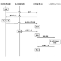
- FIG. 28 is a diagram showing an example of the operation of the range finder system 100 in this modified example.
- FIG. 28 shows the relationship between the operation of the LiDAR sensor 110, other rangefinders, the storage device 130, and the map acquisition device 180.
- the receiving device 181 of the map acquisition device 180 communicates with an external computer such as a map server via a distribution network to acquire map information.
- the matching device 182 refers to the point cloud data 131 stored in the storage device 130, matches the point cloud with the map, and identifies the structure on the map corresponding to the position of the point in the point cloud data 131. ..
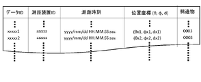
- FIG. 30 is a diagram showing an example of the point cloud data 131 stored in the storage device 130 in this modified example.
- the point cloud data 131 in this example includes the ID of each point, the distance measuring device ID, the distance measuring time, the position coordinates of the point, and the information of the structure corresponding to the position of the point.
- the association between the structure and the position of the point is executed by the processor of the storage device 130 based on the information shown in FIG. 29A.
- the LiDAR sensor 110 When the LiDAR sensor 110 acquires the update signal from the storage device 130, it refers to the point cloud data 131 and the position information of the structure stored in the storage device 130, and there is no valid number of data points in the three-dimensional space. Extract the blank area.
- the LiDAR sensor 110 in this modification preferentially measures a region that is a blank region even though it is a position where a structure exists. As a result, the area where the structure is likely to exist can be preferentially measured.
- the LiDAR sensor 110 converts the point cloud data acquired by distance measurement into a representation in the coordinate system of the point cloud data 131 and transmits it to the storage device 130.
- the storage device 130 updates the point cloud data 131 by adding the transmitted point cloud data to the existing point cloud data 131.
- Step S2460> The processing circuit 113 determines whether the selected block is one of a plurality of adjacent blocks that overlap the range of position coordinates of a single structure. When projected onto the xz plane, if the range of the selected block overlaps the range of one of the structures, and the range of that structure also overlaps the range of other extraction blocks close to that block, the step. Proceed to S2330. In other words, if a plurality of adjacent data point infrequent blocks overlap the range of a single structure when projected onto the xz plane, the process proceeds to step S2330. When the selected block does not overlap the range of any structure on the xz plane, and when the selected block and the range of the structure overlap on the xz plane, the range of the structure is adjacent to the block. If it does not overlap with other extraction blocks, the process proceeds to step S1470.
- the processing circuit 113 compares the priorities of one or more blank areas recorded in the storage device 114, prioritizes them in descending order of priority, and stores the information in the storage device 114.
- FIG. 32 is a diagram showing an example of information stored in the storage device 114 in this modified example.
- information on the position, priority, and priority of the structure is stored.
- the recognition result information is not recorded for the blank area that is not associated with any of the structures.
- the processing circuit 113 refers to the storage device 130 and extracts the position information of the structure corresponding to the blank area.
- the processing circuit 113 calculates the priority by multiplying the weights ⁇ d, ⁇ , and ⁇ calculated in steps S2473, S2414, and S2415. That is, in the present embodiment, the product of ⁇ d, ⁇ , and ⁇ is set as the priority.
- step S2418 the processing circuit 113 records the priority calculated in step S2473 in the storage device 114 in association with the blank area. For example, the priority is recorded for each blank area in the format shown in FIG. 32.
- FIG. 35A exemplifies the operation when the point cloud data is updated by inputting data points by two rangefinders other than the LiDAR sensor 110.
- FIG. 35B exemplifies the operation when the update of the point cloud data is due to the coordinate transformation by the movement or rotation of the moving body equipped with the system 10.
- the coordinate conversion parameters are sent from the control device 200 of the system 10 to the storage device 130.
- the processor of the storage device 130 updates the point cloud data 131 by performing coordinate conversion of the point cloud data 131 based on the coordinate conversion parameters.
- the storage device 130 sends the coordinate conversion parameter to the LiDAR sensor 110 together with the update signal.
- the LiDAR sensor 110 records the result of distance measurement already in the storage device 130. At this time, if the position or orientation of the moving body has changed as shown in FIG. 35 (B), the coordinate conversion to the coordinate system after the re-update is performed.
- FIG. 36 is a flowchart showing the operation of the LiDAR sensor 110 in this embodiment.
- FIG. 36 includes an operation common to that of FIG.
- the points different from those in FIG. 10 will be mainly described.
- the processing circuit 113 refers to the point cloud data 131 recorded in the storage device 130, divides the three-dimensional space into a plurality of blocks, extracts blocks having low frequency of data points, and sets each block as an adjacent block. Judge whether area integration is possible and extract a blank area. In the present embodiment, when the update signal is received from the storage device 130 in the process of extracting the blank area, the processing circuit 113 stops the operation of step S3100 and proceeds to step S3200. The details of the blank area extraction operation in S3100 will be described later.
- Step S3200> The processing circuit 113 determines whether the operation of extracting the blank area in step S3100 is completed or stopped during the operation. In other words, it is determined whether or not the determination process for all blocks is completed and the generation and extraction of the blank area is completed. If the extraction of the blank area is completed, the process proceeds to step S3300. If the extraction of the blank area is not completed, the process proceeds to step S3600.
- Step S3300 The processing circuit 113 measures the distance to the blank area extracted in step S3100. In the present embodiment, when an update signal is received from the storage device 130 during the operation of step S3300, the processing circuit 113 stops the operation of step S3300. The details of the operation of step S3300 will be described later.
- Step S3500 The processing circuit 113 expresses the distance measurement result of the blank area already recorded in the storage device 114 at the time when the operation of step S3400 is stopped by the same coordinate system as the point cloud data 131 recorded in the storage device 130. Is converted to and transmitted to the storage device 130. The details of the operation of step S3500 will be described later.
- Step S1600> The processing circuit 113 converts the coordinates of the data points measured for each blank area in step S3300 into a representation in the same coordinate system as the point cloud data recorded in the storage device 130, and transmits the coordinates to the storage device 130. At this time, the blank area of the storage device 114 is deleted. After the operation of step S1600, the process returns to step S1100.
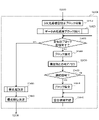
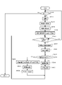
- FIG. 37 is a flowchart showing the details of the operation of step S3100.
- step S3110 is added between step S1430 and step S1440 in the flowchart shown in FIG.
- the operations other than step S3110 are the same as the operations shown in FIG. The operation of step S3110 will be described below.
- FIG. 38 is a flowchart showing the details of the operation of step S3300.
- step S3310 is added between steps S1510 and S1520 in the flowchart shown in FIG.
- the operations other than step S3310 are the same as the operations shown in FIG. The operation of step S3310 will be described below.
- Step S3310> The processing circuit 113 determines whether or not the update signal of the point cloud data is output from the storage device 130 again after the determination in step S1200. In other words, the processing circuit 113 determines whether or not the update signal has been acquired at a time after the operation time of step S1200.
- step S3300 is stopped and the process proceeds to step S3400. If there is no re-update, the process proceeds to step S1520.
- FIG. 39 is a flowchart showing the details of the operation of recording the point cloud data in the blank area that has been distance-measured in step S3500 in the storage device 130.
- Step S3500 includes steps S3510 to S3530 shown in FIG. 39. The operation of each step will be described below.
- Step S3530> The processing circuit 113 outputs the information of the data points for which the distance measurement has been performed until the distance measurement operation is interrupted in step S3310 to the storage device 130, and updates the point cloud data 131.
- step S3500 the data of the point cloud measured before the update of the point cloud data 131 is recorded, but the information in the blank area may be deleted without recording and the process may return to step S1300. ..
- the point cloud data 131 can be continuously updated in a short period of time.
- the LiDAR sensor 110 immediately corresponds to the updated point cloud data 131 even if the point cloud data 131 is updated during the blank area extraction operation or the blank area distance measurement operation. be able to.
- the data points measured before the update can be utilized.
- the LiDAR sensor 110 may prioritize the blank areas and measure the distance in order from the blank areas having the highest priority. According to such a configuration, when the point cloud data 131 is re-updated, it is highly likely that the distance measurement of the blank area having a high priority is performed, so that the point cloud data is updated frequently. Even in this case, the data points can be efficiently complemented in the blank area.
- Step S3700> The processing circuit 113 determines whether or not the update of the point cloud data 131 is due to the update of the coordinates. If the coordinates of the point cloud data 131 have been updated, the process proceeds to step S3900. If the coordinates have not been updated, the process proceeds to step S3800.
- Step S3800> The processing circuit 113 outputs the information of the data points for which the distance measurement has been performed before the distance measurement operation is interrupted to the storage device 130, and updates the point cloud data 131.
- Step S4100> The processing circuit 113 outputs the information of the data points whose coordinates have been converted in step S3900 to the storage device 130, and updates the point cloud data 131.
- Step S4400 The processing circuit 113 resets the priority for each area based on the range of the blank area converted in step S4300, and determines the priority of the area. The method of determining the priority order will be described later. After step S4400, the process returns to step S3300.
- Step S2417 The processing circuit 113 calculates the priority by multiplying the respective weights calculated in steps S2414, S2415, and S2416.
- Step S2418 The processing circuit 113 records the priority calculated in step S2417 in the storage device 114. After the operation of step S2418, the process returns to step S4410.
- FIG. 44 is a diagram showing an outline of the operation of the range finder system 100 of the present embodiment.
- the stereo camera 120 of the range finder system 100 takes pictures with the left camera 121 and the right camera 122, respectively, and matches the two acquired images.
- the image processing circuit 123 divides the image of the left camera 121, which is a reference image, into small blocks, and extracts an area of the image of the right camera 122 that matches the image in the small blocks. At this time, the image processing circuit 123 records the information of the pixels of the small blocks that could not be matched in the storage device 190.
- the LiDAR sensor 110 When the LiDAR sensor 110 acquires the update signal output by the storage device 130, it refers to the point cloud data 131 recorded in the storage device 130, extracts a blank area, and measures the distance of the blank area. The LiDAR sensor 110 transmits the distance measurement result to the storage device 130, and the storage device 130 updates the point cloud data 131.
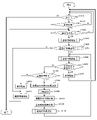
- FIG. 45 is a flowchart showing a specific example of the operation of the stereo camera 120.
- the stereo camera 120 starts the operation based on the start signal by the control circuit 160, and executes the operations of steps S5100 to S6200 shown in FIG. 45. The operation of each step will be described below.
- Step S5200> The left camera 121 and the right camera 122 simultaneously shoot a scene based on the shooting control signal output by the image processing circuit 123.
- the image processing circuit 123 performs edge detection processing on each of the right image captured by the left camera 121 and the left image captured by the right camera 122. Edge detection can be performed by a general method such as the Canny method.
- Step S5400 The image processing circuit 123 determines whether or not all the pixels on the edge on the left image, which is the reference image, have been matched with the pixels of the right image. When the matching process is performed on all the pixels on the edge in the left image, the process returns to step S5100. If there are pixels on the edge that have not yet been matched in the left image, the process proceeds to step S5500.
- Step S5500 The image processing circuit 123 selects a pixel on the edge detected in step S5300 among the pixels of the left image which is the reference image and which has not been matched with the pixel of the right image.
- Step S5900 The image processing circuit 123 transmits the information of the data points whose coordinates have been converted in step S5800 to the storage device 130, and updates the information of the point cloud data 131. After the operation of step S5900, the process returns to step S5400.
- step S6000> the image processing circuit 123 records in the storage device 190 the pixels on the edge of the left image that cannot be matched with the pixels on the right image.
- Step S6100 The image processing circuit 123 converts the coordinates of the pixels recorded in the storage device 190 in step S6000 into vectors in the coordinate system of the point cloud data 131.
- the conversion parameters are stored in advance in the memory of the image processing circuit 123.
- Step S6200 The vector whose coordinates have been converted in step S6100 is recorded in the storage device 190. After the operation of step S6200, the process returns to step S5400.
- FIG. 47 is a flowchart showing the operation of the LiDAR sensor 110 in this embodiment.
- the operations of steps S2100, S2200, S2300, and S1500 in the flowchart of the second embodiment shown in FIG. 22 are replaced with steps S7100, S7200, and S7300.
- steps S7100, S7200, and S7300 are replaced with steps S7100, S7200, and S7300.
- an operation different from the operation of FIG. 22 will be described.
- the process proceeds to step S7100.
- the processing circuit 113 acquires information on the pixel position on the nearest edge from the storage device 190.
- the pixels recorded in the storage device 190 are pixels that cannot correspond to the pixels on the other image while the edges are extracted on the reference image in the processing of the stereo camera 120.
- the processing circuit 113 extracts one or more blank areas with reference to the point cloud data 131 recorded in the storage device 130, and blanks based on the position information of the pixels on the edge recorded in the storage device 190. Determine the priority of the area. The details of the priority determination method will be described later.
- Step S7300 The processing circuit 113 measures the distance for each blank area extracted in step S7200 and recorded in the storage device 114.
- the processing circuit 113 determines the beam emitting direction in the direction of the vector corresponding to the pixel on the edge included in the blank region, controls the beam scanner 111 and the light receiving device 112, and performs distance measurement. The details of the operation of step S7300 will be described later.
- Step S1600> The processing circuit 113 converts the coordinates of the data points measured for each blank area in step S7300 into a representation in the same coordinate system as the point cloud data recorded in the storage device 130, and transmits the coordinates to the storage device 130. .. At this time, the information in the blank area in the storage device 114 is deleted. After the operation of step S1600, the process returns to step S1100.
- the LiDAR sensor 110 detects an edge from the image acquired by the stereo camera 120 when the point cloud data 131 is updated based on the distance measurement result by the stereo camera 120. Nevertheless, the distance measurement can be performed with priority given to the blank area where the correspondence between the two images cannot be obtained, and the information of the point cloud data 131 can be complemented.
- Step S7210> The processing circuit 113 was selected by referring to the vector information of the pixels on the edge that could not be matched between the two images acquired in step S7100 and extracting the vector of the pixels on the edge included in the selected block. Associate the block with the vector of pixels on the edge. If the selected block does not contain a vector of pixels on the edge, no mapping is done.
- Step S7220 When it is determined in step S1430 that the processing for all the extraction blocks is completed, the processing circuit 113 determines that each of the blank areas recorded in the storage device 114 is based on the number of edge vectors in the blank area. Determine the priority. The details of the priority determination method will be described later.
- the processing circuit 113 compares the priorities of one or more blank areas recorded in the storage device 114, prioritizes them in descending order of priority, and records the information in the storage device 114.
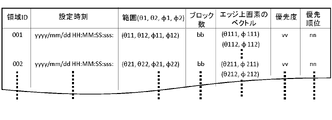
- FIG. 49 is a diagram showing an example of information recorded in the storage device 114 in the present embodiment.
- the area ID, the set time, the range of the area, the number of blocks constituting the area, the vector of the pixels on the edge included in the area, the priority, and the priority are recorded. Will be done. It should be noted that one blank area may include a vector of a plurality of pixels on the edge.
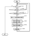
- FIG. 50 is a flowchart showing the details of the operation of calculating the priority of step S7220.
- Step S7220 includes steps S7221 and S7222. The operation of each step is as follows.
- the processing circuit 113 counts the number of pixels on the edge that cannot be matched by the two images acquired by the stereo camera 120 associated with the blank area, and calculates the number of pixels per unit block.
- Step S7222> The processing circuit 113 records the priority in the storage device 114 for each blank area, with the number of edges per unit block obtained in step S7221 as the priority.
- FIG. 51 is a flowchart showing the details of the range finder operation in step S7300.
- Step S7300 includes steps S7310 to S7380. The operation of each step will be described below.
- Step S7320> The processing circuit 113 selects the blank area having the highest priority among the blank areas for which the distance measurement process has not been completed.
- the processing circuit 113 converts the position information of the data points measured as points in the coordinate system set in the LiDAR sensor 110 into the coordinate system of the point cloud data 131.
- the distance measurement in the edge direction can be completed for all the points on the edge associated with the blank area and not measured by the stereo camera 120.
- the LiDAR sensor 110 measures the distance in all the directions of the pixels on the edge.
- the operation is not limited to this, and for example, for a plurality of adjacent pixels, a representative pixel may be determined within those pixels, and distance measurement may be performed only in the direction of the representative pixel.
- step S7300 in the present embodiment if the blank area does not include an edge that cannot be dealt with by the stereo camera, the loop is terminated without measuring the distance in the blank area. It is not limited to such an operation, and may be combined with a method of setting a direction in a blank area and performing distance measurement as in the first embodiment, and distance measurement may be performed even in a blank area not including an edge. You may.
- the distance measuring system includes a stereo camera as a distance measuring device other than the LiDAR sensor
- the feature points for example, edges
- the distance cannot be calculated and data points cannot be generated.
- the LiDAR sensor 110 can preferentially measure the distance in the region where the data point is not generated even though the edge is present.
- the priority of distance measurement is determined based on the number of pixels on the edge associated with the blank area.
- the area surrounded by the edge is preferentially measured by increasing the priority of the blank area inside the closed curve detected from the image taken by the stereo camera 120. ..
- Step S8100> The image processing circuit 123 extracts an edge forming a closed curve from the edge extracted in step S5300, and assigns an ID to the extracted closed curve.
- the method of determining the closed curve is, for example, a method of fitting a closed curve model or connecting those having close edge endpoints.
- Step S8200> The image processing circuit 123 extracts the pixels inside the closed curve using the closed curve extracted in step S8100, and records the information of the extracted pixels in the storage device 190 in association with the ID of the closed curve.
- a method of specifying the pixels inside the closed curve for example, a method using a complex function theorem, a method based on the number of intersections with the closed curve from a specific point, or the like can be used.
- steps S5400 to S5900 is the same as the operation of the corresponding step shown in FIG. 45.
- edge information is used to specify the pixels inside the closed curve, but instead of using edge information, other methods such as machine learning may be used. For example, pixels inside a plurality of regions divided by using a deep learning algorithm such as semantic segmentation or instance segmentation may be specified as pixels inside a closed curve.
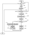
- FIG. 54 is a flowchart showing a specific example of the operation of the LiDAR sensor 110 in this modified example.
- steps S7100 to S7300 in the flowchart shown in FIG. 47 are replaced with steps S8500 to S8700. The operation of these steps will be described below.
- Step S8500 The processing circuit 113 acquires the information of the latest extracted pixel from the storage device 190.
- the processing circuit 113 extracts one or more blank areas with reference to the point cloud data 131 recorded in the storage device 130, and determines the priority of the blank areas based on the information recorded in the storage device 190. .. The details of the priority determination method will be described later.
- Step S8700> The processing circuit 113 measures the distance for each blank area recorded in the storage device 114. The details of the method for determining the distance measuring direction will be described later.
- the LiDAR sensor 110 shows an edge in the image acquired by the stereo camera 120 when the point group data 131 in the storage device 130 is updated based on the distance measurement result by the stereo camera 120. It is possible to supplement the information of the point group data 131 by performing distance measurement with priority given to the region in the closed curve.
- FIG. 55 is a flowchart showing the details of the operation of extracting the blank area and determining the priority in step S8600.
- steps S7210 and S1450 in the flowchart shown in FIG. 48 are replaced by steps S8610 and S8620, and step S7220 is replaced by step S8630.
- step S8630 the operation of the step different from that of FIG. 48 will be described.
- the processing circuit 113 refers to the pixel information acquired in step S8500 and extracts the pixel information included in the selected block.
- FIG. 56 is a diagram showing an example of information stored in the storage device 114.
- the closed curve ID is recorded.
- Step S8630 The processing circuit 113 determines the priority of each of the blank areas recorded in the storage device 114 based on the edge information and the closed curve information of the vector in the area. Details of the method for determining the priority in step S8630 will be described later.
- the processing circuit 113 compares the priorities of the blank areas recorded in the storage device 114, prioritizes them in descending order of priority, and records the information in the storage device 114.
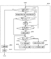
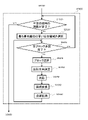
- FIG. 57 is a flowchart showing the details of the operation of step S8630.
- Step S8630 includes steps S8631 to S8638 shown in FIG. 57. The operation of each step will be described below.
- Step S8631> The processing circuit 113 determines whether or not the priority calculation has been completed for all the blank areas recorded in the storage device 114. If the priority calculation is completed in all the blank areas, the process proceeds to step S2420. If there is a blank area for which the priority calculation has not been completed, the process proceeds to step S8632.
- Step S8632> The processing circuit 113 selects one blank area for which the priority calculation has not been completed, out of the blank areas recorded in the storage device 114.
- Step S8634> The processing circuit 113 selects a vector in the blank area for which the weight calculation has not been completed.
- the processing circuit 113 determines the weight ⁇ e based on the edge information of the vector.
- the weight ⁇ e can be determined, for example, according to a predetermined table or function.
- the weight ⁇ e can be determined according to a table that defines the correspondence between the edge information and the weight.
- FIG. 59 shows an example of a table that defines the correspondence between edge information and weights.
- the vector corresponding to the pixels other than the edge is given a weight of 0.1
- the vector corresponding to the pixel on the edge is given a weight of 1.0.
- the numerical values in the table shown in FIG. 59 are examples, and are not limited to these.
- Step S8637 The processing circuit 113 determines the weight of the vector by multiplying the weight ⁇ c determined in step S8635 by the weight ⁇ e determined in step S8636. After the operation of step S8637, the process returns to step S8633.
- the weights can be calculated for all the vectors in the blank area recorded in the storage device 114.
- the processing circuit 113 calculates the priority of the blank area by adding and averaging all the weights of the vectors in the blank area, and records the priority in the storage device 114 in association with the blank area.
- step S8631 By repeating the operations from step S8631 to step S8638, the priority of all the blank areas recorded in the storage device 114 can be calculated.
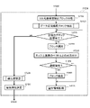
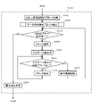
- FIG. 60 is a flowchart showing the details of the range finder operation in step S8700 shown in FIG. 54.
- distance measurement is performed for the directions of pixels on the edges that cannot be matched between the two images acquired by the stereo camera 120.
- distance measurement is performed not only on the edge in the blank area but also in the direction inside the blank area. The operation of each step will be described below.
- Step S7310> The processing circuit 113 determines whether or not the distance measurement of all the blank areas recorded in the storage device 114 is completed. When the distance measurement of all the blank areas is completed, the process proceeds to step S1600. If there is a blank area for which distance measurement has not been completed, the process proceeds to step S7320.
- Step S7320> The processing circuit 113 selects the blank area having the highest priority among the blank areas for which the distance measurement process has not been completed.
- the processing circuit 113 divides the blank area into a plurality of partial areas.
- the division may be performed in units of predetermined angles for each of the x-axis direction and the y-axis direction. For example, it can be divided in units of 2 degrees in the x-axis direction and 2 degrees in the y-axis direction.
- Step S8730> The processing circuit 113 determines whether or not the distance measurement for all the divided regions divided in step S8720 is completed. When the distance measurement for all the divided regions is completed, the process returns to step S7310. If there is a divided area for which distance measurement has not been completed, the process proceeds to step S8740.
- Step S8740 The processing circuit 113 selects a divided region for which distance measurement has not been completed from the divided regions divided in step S8720.
- Step S8750 The processing circuit 113 determines whether or not the distance measurement of the pixels on all the edges in the selected divided region has been completed. When the distance measurement of the pixels on all the edges in the divided region is completed, the process proceeds to step S8770. If there is an edge in the divided region for which distance measurement has not been completed, the process proceeds to step S8760.
- Step S8760> The processing circuit 113 selects pixels on the edge in the divided region for which distance measurement has not been completed.
- Step S8770 The processing circuit 113 sets the direction of the edge selected in step S8760 to the beam emitting direction, and transmits a control signal to the beam scanner 111 and the light receiving device 112 to execute distance measurement. After the operation of step S8770, the process returns to step S8750.
- the processing circuit 113 calculates the central angle ⁇ c of the angle range in the x-axis direction of the divided region and the central angle ⁇ c of the angle range in the y-axis direction.
- Step S8790 The processing circuit 113 sets the directions of ⁇ c and ⁇ c calculated in step S8780 to the beam emitting direction, and transmits a control signal to the beam scanner 111 and the light receiving device 112 to execute distance measurement. After the operation of step S8790, the process returns to step S8730.
- the distance can be measured with respect to the direction of the pixels on the edge in the blank area selected in step S7320 and the center direction in the blank area.
- the distance is measured in the central direction in the blank area, but any one or more directions in the blank area may be determined and the distance may be measured in that direction.
- the processing circuit 113 converts the coordinates of the data points recorded in the storage device 114 in the completely blank area into the values in the coordinate system of the point cloud data 131.
- Step S8810> The processing circuit 113 transmits the coordinates of the data points whose coordinates have been converted in step S8800 to the storage device 130, and updates the point cloud data 131.
- the blank area inside the closed curve is preferentially measured.
- the priority of distance measurement is determined based on the number of pixels on the edge associated with the blank area. Further, in the first modification of the fourth embodiment, the priority of the blank area inside the closed curve in the image taken by the stereo camera 120 is set high, and the area surrounded by the edge is preferentially measured. On the other hand, in the second modification of the fourth embodiment, in the image captured by the stereo camera 120, a region in which the reliability of stereo matching that occurs when the edge and the epipolar line overlap is lowered, or a blank region due to the edge is reduced. The priority is set high, and the area on the line segment connecting the pixel of interest and the center of the camera is prioritized for distance measurement.
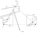
- FIG. 61 is a diagram for explaining a three-dimensional measurement method of an edge portion of the stereo camera 120 with reference to the left camera 121.
- an example of a method of finding the three-dimensional position of the point P1 on the object 410 composed of edges such as a fence will be described.
- the point P2R is an epipolar passing through the projection position er of the left camera 121 on the projection surface 122P of the right camera 122. It can be calculated as a point on line 430. Since the point P1R exists on the epipolar line 430, the position of the point P1R can be specified by performing matching processing only on the epipolar line 430. Here, if the angle at which the edge where the point P1 exists and the epipolar line 430 intersect is larger than a predetermined value, the point P1R can be obtained with high accuracy.
- the area corresponding to the plurality of blocks existing on the line segment 440 in front of the projection surface 121P of the left camera 121 is preferentially measured by the LiDAR sensor to measure the distance to the point P2. It is possible to measure the three-dimensional position of the above with high accuracy.
- the configuration of the moving body control system 10 and the range finder system 100 in this modification is the same as the configuration of the fourth embodiment.
- the points different from those of the fourth embodiment will be mainly described.
- FIG. 64 is a diagram showing an outline of the operation of the range finder system 100 in the second modification of the fourth embodiment.
- the rangefinder other than the LiDAR sensor 110 is the stereo camera 120.
- FIG. 65 is a flowchart showing the operation of the LiDAR sensor 110 in this modified example.
- steps S8500 to S8700 in the flowchart shown in FIG. 54 are replaced with steps S9100 to S9300.
- step S1200 in addition to the update signal indicating that the point cloud data 131 has been updated, the information of the camera ID which is the identification code of the stereo camera 120 is also received.
- points different from the operation shown in FIG. 54 will be described.
- Step S9100 The processing circuit 113 acquires the camera center coordinates of the stereo camera 120 previously recorded in the storage device 114 based on the camera ID acquired in step S1200.
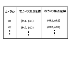
- FIG. 66 is a diagram showing an example of information indicating the camera center coordinates of the stereo camera 120 recorded in the storage device 114.
- the camera center coordinates correspond to the coordinates of the point Ol and the point Or shown in FIG. 63.
- the camera ID that identifies the stereo camera 120, the camera center coordinates of the left camera 121 of each stereo camera 120, and the camera center coordinates of the right camera 122 are represented by the coordinate system of the point group data 131. There is. This information is used to identify the epipolar surface of the stereo camera 120.
- the processing circuit 113 refers to the point cloud data 131 recorded in the storage device 130, and as illustrated in FIG. 63, the point Ol and the point P2L at the center coordinates of the left camera 121 of the stereo camera 120 acquired in step S9100.
- the line segment 440 connecting the above one or more areas in front of the projection surface 121P of the left camera 121 are extracted as blank areas. Further, the priority of the blank area is determined based on the size of the blank area on the same epipolar surface. The details of the blank area extraction method will be described later.
- Step S1600 The processing circuit 113 converts the coordinates of the data points measured in step S9300 into the same coordinate system as the point cloud data 131, and transmits the coordinates to the storage device 130. At this time, the blank area of the storage device 114 is deleted. After the operation of step S1600, the process returns to step S1100.
- the LiDAR sensor 110 is left and right because it is on the same epipolar line in the stereo camera 120 when the point cloud data 131 is updated based on the distance measurement result by the stereo camera 120. It is possible to efficiently supplement the information of the point cloud data 131 by preferentially measuring the distance in the blank area where the data points could not be acquired due to the lack of correspondence between the images of.
- FIG. 67 is a flowchart showing the details of the operation of step S9200.
- the operations of steps S1410 to S1440 and step S2420 are the same as the operations of the corresponding steps shown in FIG. 55.
- points different from the operation of FIG. 55 will be described.
- the processing circuit 113 generates an epipolar surface that passes through the block selected in step S1440.
- the processing circuit 113 generates a plane passing through the focal position coordinates of the left and right cameras 121 and 122 acquired in step S9100 and the center point of the block as an epipolar surface of the block.
- Step S9220 Among the blocks extracted in step S1420, a block adjacent to the block and on the epipolar surface generated in step S9210 is selected. If there is a corresponding block, the process proceeds to step S1460. If there is no corresponding block, the process proceeds to step S1470.
- Step S1460 The processing circuit 113 combines the blocks with adjacent blocks or regions including adjacent blocks and integrates them as regions. After step S1460, the process returns to step S9220.
- step S9220 and step S1460 By repeating step S9220 and step S1460, adjacent blocks having a low frequency of valid data points on the same epipolar surface can be combined to generate as large a blank area as possible.
- Step S1470 The processing circuit 113 records a continuous area composed of one or more blocks in the storage device 114 as a blank area.
- FIG. 68 is a diagram showing an example of information recorded in the storage device 114. In this example, the area ID, the time when the area is set, and the coordinate range of all the combined blocks are recorded for each blank area. After step S1470, the process returns to step S1430.
- steps S1430 to S1470 By repeating the operations of steps S1430 to S1470, adjacent blocks are grouped into one blank area for all the blocks extracted in step S1420, and the information for each area is stored.
- the processing circuit 113 sets the priority of distance measurement with respect to one or more blank areas recorded in the storage device 114.
- the priority can be determined, for example, in descending order of the number of combined blocks. Since the blocks are combined on the same epipolar surface, priority is given to a blank area where there is a high possibility that there are many data points that the stereo camera 120 could not acquire.
- the polar coordinate space of the point cloud data 131 is divided into a plurality of blocks, and in step S1420, blocks having a frequency of data points less than a certain number are extracted from all the divided blocks.
- the operation is not limited to such an operation, and for example, the above processing may be performed only within the range-finding range of the stereo camera 120 identified by the camera ID.
- FIG. 69 is a flowchart showing the details of the distance measuring operation of the blank area by the LiDAR sensor 110 in step S9300 shown in FIG. 65. The operation of each step will be described below.
- Step S2520> The processing circuit 113 selects the blank area having the highest priority from the blank areas for which distance measurement has not yet been performed.
- Step S9310 The processing circuit 113 determines whether or not the distance measurement for all the blocks included in the blank area selected in step S2520 has been completed. When the distance measuring operation of all the blocks included in the blank area is completed, the process returns to step S1510. If there is a block included in the blank area for which distance measurement has not yet been performed, the process proceeds to step S9320.
- Step S9330> The processing circuit 113 determines the center of the block range selected in step S9320 as the beam emission direction.
- Step S1550 The processing circuit 113 uses the coordinate system of the point cloud data 131 to obtain the three-dimensional coordinates of the data points obtained from the distance data acquired in step S1540 and the information on the emission direction of the beam from the values in the coordinate system of the LiDAR sensor 110. Convert to the value of.
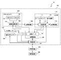
- FIG. 70 is a block diagram of a range finder system 10 for explaining a modification 3 of the fourth embodiment.
- FIG. 70 is the same as that of FIG. 43 except that the stereo camera 120 of FIG. 43 is replaced with the monocular rangefinder camera 124.
- FIG. 71 is an example of a flowchart showing the operation of the monocular rangefinder camera 124 in this modified example.
- the monocular rangefinder camera 124 starts the operation based on the start signal by the control circuit 160, and executes the operation shown in FIG. 71. The operation of each step will be described below.
- Step S6500> The camera 125 shoots the target scene based on the shooting control information output by the image processing circuit 123.
- the image processing circuit 123 performs image recognition processing on the image captured in step S6500.
- the image recognition process can be performed by a general method such as machine learning. By image recognition, an object in an image is identified, and pixels included in the object and pixels not included in the object are divided.
- Step S6520 The image processing circuit 123 determines whether or not the processing has been completed for all the objects recognized in step S6510. When the processing has been completed for all the recognized objects, the process returns to step S5100. If the process is not completed, the process proceeds to step S6530.
- Step S6530> The image processing circuit 123 selects a pixel region included in the object whose processing has not been completed from the objects recognized in step S6510.
- the image processing circuit 123 extracts, for example, edges, textures, and the like, which can determine the blur in the pixel region included in the object selected in step S6530.
- the image processing circuit 123 estimates the distance to the object based on the degree of blurring.
- the estimation method can be performed by, for example, a method of measuring the aberration map distance using a point spread function (PSF).
- PSF point spread function
- Step S6560 The image processing circuit 123 determines whether or not the estimated likelihood is higher than a predetermined value with respect to the estimation result in step S6550. If the estimated likelihood is higher than the predetermined value, the process proceeds to step S5800. If the estimated likelihood is lower than the predetermined value, the process proceeds to step S6570.
- the method of determining the estimated likelihood can be calculated using, for example, the variance of the distance estimates within the object.
- Step S6570> The image processing circuit 123 sets the pixel region included in the object whose distance estimation probability is determined to be low in step S6560 and the pixel forming the edge of the object as pixels having the distance estimation probability low, and stores them in the storage device 190. ..
- steps S5800 to S5900 and steps S6100 to S6200 are the same as those in FIG. 45 of the fourth embodiment.
- the distances of all the objects recognized in the image are estimated.
- the distance is estimated for all the objects detected by the monocular rangefinder camera 124, and the pixels having a low estimation likelihood of the distance are recorded in the storage device 190 as a blank area and LiDAR.
- Distance measurement processing can be performed by the sensor.
Landscapes
- Engineering & Computer Science (AREA)
- Physics & Mathematics (AREA)
- General Physics & Mathematics (AREA)
- Radar, Positioning & Navigation (AREA)
- Remote Sensing (AREA)
- Computer Networks & Wireless Communication (AREA)
- Electromagnetism (AREA)
- Theoretical Computer Science (AREA)
- Computer Vision & Pattern Recognition (AREA)
- Multimedia (AREA)
- Optical Radar Systems And Details Thereof (AREA)
Priority Applications (4)
| Application Number | Priority Date | Filing Date | Title |
|---|---|---|---|
| EP21919544.3A EP4279957A4 (en) | 2021-01-13 | 2021-11-09 | DISTANCE MEASUREMENT SYSTEM |
| JP2022575090A JPWO2022153653A1 (https=) | 2021-01-13 | 2021-11-09 | |
| CN202180088417.6A CN116615670A (zh) | 2021-01-13 | 2021-11-09 | 测距系统 |
| US18/342,768 US20230341558A1 (en) | 2021-01-13 | 2023-06-28 | Distance measurement system |
Applications Claiming Priority (2)
| Application Number | Priority Date | Filing Date | Title |
|---|---|---|---|
| JP2021003203 | 2021-01-13 | ||
| JP2021-003203 | 2021-01-13 |
Related Child Applications (1)
| Application Number | Title | Priority Date | Filing Date |
|---|---|---|---|
| US18/342,768 Continuation US20230341558A1 (en) | 2021-01-13 | 2023-06-28 | Distance measurement system |
Publications (1)
| Publication Number | Publication Date |
|---|---|
| WO2022153653A1 true WO2022153653A1 (ja) | 2022-07-21 |
Family
ID=82447137
Family Applications (1)
| Application Number | Title | Priority Date | Filing Date |
|---|---|---|---|
| PCT/JP2021/041251 Ceased WO2022153653A1 (ja) | 2021-01-13 | 2021-11-09 | 測距システム |
Country Status (5)
| Country | Link |
|---|---|
| US (1) | US20230341558A1 (https=) |
| EP (1) | EP4279957A4 (https=) |
| JP (1) | JPWO2022153653A1 (https=) |
| CN (1) | CN116615670A (https=) |
| WO (1) | WO2022153653A1 (https=) |
Cited By (4)
| Publication number | Priority date | Publication date | Assignee | Title |
|---|---|---|---|---|
| CN115457133A (zh) * | 2022-09-16 | 2022-12-09 | 长春工程学院 | 一种基于外形框架优先的三维点云数据存储方法 |
| CN117036464A (zh) * | 2023-07-27 | 2023-11-10 | 浙江工业大学 | 基于实例分割技术的单目视觉引导agv避障测距方法和装置 |
| JP2024051741A (ja) * | 2022-09-30 | 2024-04-11 | Dolphin株式会社 | 物体検出システム、物体検出方法及びプログラム |
| WO2024142607A1 (ja) * | 2022-12-28 | 2024-07-04 | 日立Astemo株式会社 | 車載処理装置及び物体認識方法 |
Families Citing this family (5)
| Publication number | Priority date | Publication date | Assignee | Title |
|---|---|---|---|---|
| KR102847126B1 (ko) * | 2021-01-18 | 2025-08-14 | 가부시키가이샤 신가와 | 위치 제어 장치, 위치 제어 방법, 위치 제어 프로그램을 저장한 기록 매체 및 본딩 장치 |
| US20240371035A1 (en) * | 2023-05-01 | 2024-11-07 | Qualcomm Incorporated | Camera and lidar cross-sensor calibration |
| GB2640277A (en) * | 2024-04-10 | 2025-10-15 | V Nova Int Ltd | Determining a location of a point |
| GB2637804A (en) * | 2024-04-10 | 2025-08-06 | V Nova Int Ltd | Determining a point of a three-dimensional representation of a scene |
| CN118602986B (zh) * | 2024-08-07 | 2024-10-25 | 成都航宇汇智科技有限公司 | 一种三维表面轮廓测量方法 |
Citations (6)
| Publication number | Priority date | Publication date | Assignee | Title |
|---|---|---|---|---|
| JPH0356549B2 (https=) | 1984-08-21 | 1991-08-28 | ||
| JP2008082707A (ja) * | 2006-09-25 | 2008-04-10 | Topcon Corp | 測量方法及び測量システム及び測量データ処理プログラム |
| JP2012013660A (ja) * | 2010-07-05 | 2012-01-19 | Topcon Corp | 点群データ処理装置、点群データ処理システム、点群データ処理方法、および点群データ処理プログラム |
| WO2013186160A1 (en) * | 2012-06-11 | 2013-12-19 | Actionphoto International As | Closed loop 3d video scanner for generation of textured 3d point cloud |
| US20180217258A1 (en) | 2017-01-31 | 2018-08-02 | Panasonic Intellectual Property Management Co., Ltd. | Imaging system |
| WO2019065536A1 (ja) * | 2017-09-26 | 2019-04-04 | パナソニック インテレクチュアル プロパティ コーポレーション オブ アメリカ | 再構成方法および再構成装置 |
Family Cites Families (7)
| Publication number | Priority date | Publication date | Assignee | Title |
|---|---|---|---|---|
| US9322646B2 (en) * | 2010-04-09 | 2016-04-26 | The Trustees Of The Stevens Institute Of Technology | Adaptive mechanism control and scanner positioning for improved three-dimensional laser scanning |
| US11194994B2 (en) * | 2017-12-20 | 2021-12-07 | X Development Llc | Semantic zone separation for map generation |
| EP3835492B1 (en) * | 2018-08-10 | 2023-03-08 | Sumitomo (S.H.I.) Construction Machinery Co., Ltd. | Remotely operated shovel |
| EP3963355A1 (en) * | 2019-03-08 | 2022-03-09 | OSRAM GmbH | Component for a lidar sensor system, lidar sensor system, lidar sensor device, method for a lidar sensor system and method for a lidar sensor device |
| US10510155B1 (en) * | 2019-06-11 | 2019-12-17 | Mujin, Inc. | Method and processing system for updating a first image generated by a first camera based on a second image generated by a second camera |
| DE112020003043T5 (de) * | 2019-06-25 | 2022-08-18 | Nvidia Corporation | Erkennung und klassifizierung von kreuzungsregionen für autonome maschinenanwendungen |
| JP2021099698A (ja) * | 2019-12-23 | 2021-07-01 | ソニーグループ株式会社 | 画像処理装置および方法、並びにプログラム |
-
2021
- 2021-11-09 WO PCT/JP2021/041251 patent/WO2022153653A1/ja not_active Ceased
- 2021-11-09 JP JP2022575090A patent/JPWO2022153653A1/ja not_active Withdrawn
- 2021-11-09 EP EP21919544.3A patent/EP4279957A4/en not_active Withdrawn
- 2021-11-09 CN CN202180088417.6A patent/CN116615670A/zh active Pending
-
2023
- 2023-06-28 US US18/342,768 patent/US20230341558A1/en active Pending
Patent Citations (6)
| Publication number | Priority date | Publication date | Assignee | Title |
|---|---|---|---|---|
| JPH0356549B2 (https=) | 1984-08-21 | 1991-08-28 | ||
| JP2008082707A (ja) * | 2006-09-25 | 2008-04-10 | Topcon Corp | 測量方法及び測量システム及び測量データ処理プログラム |
| JP2012013660A (ja) * | 2010-07-05 | 2012-01-19 | Topcon Corp | 点群データ処理装置、点群データ処理システム、点群データ処理方法、および点群データ処理プログラム |
| WO2013186160A1 (en) * | 2012-06-11 | 2013-12-19 | Actionphoto International As | Closed loop 3d video scanner for generation of textured 3d point cloud |
| US20180217258A1 (en) | 2017-01-31 | 2018-08-02 | Panasonic Intellectual Property Management Co., Ltd. | Imaging system |
| WO2019065536A1 (ja) * | 2017-09-26 | 2019-04-04 | パナソニック インテレクチュアル プロパティ コーポレーション オブ アメリカ | 再構成方法および再構成装置 |
Non-Patent Citations (1)
| Title |
|---|
| See also references of EP4279957A4 |
Cited By (6)
| Publication number | Priority date | Publication date | Assignee | Title |
|---|---|---|---|---|
| CN115457133A (zh) * | 2022-09-16 | 2022-12-09 | 长春工程学院 | 一种基于外形框架优先的三维点云数据存储方法 |
| JP2024051741A (ja) * | 2022-09-30 | 2024-04-11 | Dolphin株式会社 | 物体検出システム、物体検出方法及びプログラム |
| JP7762431B2 (ja) | 2022-09-30 | 2025-10-30 | Dolphin株式会社 | 物体検出システム、物体検出方法及びプログラム |
| WO2024142607A1 (ja) * | 2022-12-28 | 2024-07-04 | 日立Astemo株式会社 | 車載処理装置及び物体認識方法 |
| CN117036464A (zh) * | 2023-07-27 | 2023-11-10 | 浙江工业大学 | 基于实例分割技术的单目视觉引导agv避障测距方法和装置 |
| CN117036464B (zh) * | 2023-07-27 | 2025-12-02 | 浙江工业大学 | 基于实例分割技术的单目视觉引导agv避障测距方法和装置 |
Also Published As
| Publication number | Publication date |
|---|---|
| EP4279957A4 (en) | 2024-06-19 |
| US20230341558A1 (en) | 2023-10-26 |
| EP4279957A1 (en) | 2023-11-22 |
| JPWO2022153653A1 (https=) | 2022-07-21 |
| CN116615670A (zh) | 2023-08-18 |
Similar Documents
| Publication | Publication Date | Title |
|---|---|---|
| WO2022153653A1 (ja) | 測距システム | |
| US12352591B2 (en) | Apparatus for acquiring 3-dimensional maps of a scene | |
| CN113625255B (zh) | 光检测和测距的系统及其方法 | |
| JP7321246B2 (ja) | ハイブリッド飛行時間型イメージャモジュール | |
| CN110377026B (zh) | 信息处理装置、存储介质和信息处理方法 | |
| US20220073035A1 (en) | Dirt detection system, lidar unit, sensing system for vehicle, and vehicle | |
| CN114375408B (zh) | 用于修改lidar视场的系统和方法 | |
| CN113227839A (zh) | 具有结构光照明器的飞行时间传感器 | |
| KR20200012037A (ko) | 다수의 가설에 의한 라이다(lidar) 디바이스 레인지 앨리어싱 회복력 | |
| JP2019046161A (ja) | 車両制御装置、車両制御方法、およびプログラム | |
| WO2021112158A1 (ja) | 無人飛行機の飛行制御システム及び地形計測システム | |
| CN117813530A (zh) | 基于传感器控制LiDAR分辨率配置 | |
| KR20190084463A (ko) | 차량 주변의 이미지를 제공하는 전자 장치 및 방법 | |
| CN107923978A (zh) | 物体检测装置、物体检测方法及程序 | |
| JP2023022138A (ja) | 光走査装置及び制御方法 | |
| TW202206849A (zh) | 用於測量的裝置及用以判定環境中兩點間之距離之方法 | |
| CN114966624B (zh) | 物体识别系统和物体识别方法 | |
| CN118225092A (zh) | 一种飞行器自动巡航方法及融合激光雷达的视觉里程计 | |
| WO2021199888A1 (ja) | 測距装置を制御する方法および装置 | |
| KR102222408B1 (ko) | 모터리스 전방위 장애물 인지 센서 | |
| KR102325124B1 (ko) | 기계 학습 및 모노 카메라로 물체의 위치 정보를 획득하는 차량 | |
| JP2024102522A (ja) | 車載検出器 | |
| Malinovskii | Modern vizualization technologies fusion–the way to artificial intellectual systems | |
| JP2024066283A (ja) | 荷役制御システム、測距制御装置、光学センサ、荷役制御方法、荷役制御プログラム | |
| WO2022269995A1 (ja) | 測距装置および方法、並びにプログラム |
Legal Events
| Date | Code | Title | Description |
|---|---|---|---|
| 121 | Ep: the epo has been informed by wipo that ep was designated in this application |
Ref document number: 21919544 Country of ref document: EP Kind code of ref document: A1 |
|
| ENP | Entry into the national phase |
Ref document number: 2022575090 Country of ref document: JP Kind code of ref document: A |
|
| WWE | Wipo information: entry into national phase |
Ref document number: 202180088417.6 Country of ref document: CN |
|
| NENP | Non-entry into the national phase |
Ref country code: DE |
|
| ENP | Entry into the national phase |
Ref document number: 2021919544 Country of ref document: EP Effective date: 20230814 |
|
| WWW | Wipo information: withdrawn in national office |
Ref document number: 2021919544 Country of ref document: EP |