WO2022145010A1 - 無線通信システム、送信装置、受信装置、及び通信方法 - Google Patents
無線通信システム、送信装置、受信装置、及び通信方法 Download PDFInfo
- Publication number
- WO2022145010A1 WO2022145010A1 PCT/JP2020/049213 JP2020049213W WO2022145010A1 WO 2022145010 A1 WO2022145010 A1 WO 2022145010A1 JP 2020049213 W JP2020049213 W JP 2020049213W WO 2022145010 A1 WO2022145010 A1 WO 2022145010A1
- Authority
- WO
- WIPO (PCT)
- Prior art keywords
- oam
- receiving device
- signal
- oam mode
- modes
- Prior art date
- Legal status (The legal status is an assumption and is not a legal conclusion. Google has not performed a legal analysis and makes no representation as to the accuracy of the status listed.)
- Ceased
Links
Images




Classifications
-
- H—ELECTRICITY
- H04—ELECTRIC COMMUNICATION TECHNIQUE
- H04J—MULTIPLEX COMMUNICATION
- H04J1/00—Frequency-division multiplex systems
Definitions
- the present invention relates to a technique for spatially multiplex transmission of a radio signal using the orbital angular momentum (OAM) of an electromagnetic wave.
- OFAM orbital angular momentum
- Non-Patent Document 1 In an electromagnetic wave having OAM, the equiphase planes are spirally distributed along the propagation direction around the propagation axis. Since electromagnetic waves having different OAM modes and propagating in the same direction have orthogonal spatial phase distributions in the rotation axis direction, the signals are multiplexed by separating the signals of each OAM mode modulated by different signal sequences in the receiving device. It is possible to transmit.
- a plurality of OAM modes are generated by using an evenly spaced circular array antenna (hereinafter referred to as UCA (Uniform Circular Array)) in which a plurality of antenna elements are arranged in a circle at equal intervals.
- UCA Uniform Circular Array
- -By synthesizing and transmitting spatial multiplex transmission of different signal sequences can be realized (for example, Non-Patent Document 2).
- a butler circuit butler matrix circuit
- a transmission device and a reception device using UCA enable large-capacity communication, but in the future, support for mobile communication is desired.
- the present invention has been made in view of the above points, and an object of the present invention is to provide a technique capable of reducing interference between OAM modes on the receiving side in a wireless transmission technique using UCA.
- a wireless communication system including a transmitting device and a receiving device.
- the transmitting device transmits a plurality of OAM mode signals
- the transmission device transmits a plurality of OAM mode signals.
- the receiving device receives the signals of the plurality of OAM modes, calculates the determination value regarding the interference between the OAM modes for each OAM mode, and compares the determination value with the threshold value to obtain the plurality of OAM modes.
- One or more OAM modes are selected from among them, and the selected one or more OAM modes are notified to the transmission device.
- a wireless communication system in which the transmitting device transmits data to the receiving device using one or more OAM modes notified from the receiving device.
- a technique capable of reducing interference between OAM modes on the receiving side is provided.
- FIG. 1 shows an example of UCA phase setting for generating an OAM mode signal.
- the UCA shown in FIG. 1 is a UCA composed of eight antenna elements.
- the signals of OAM mode 0, 1, 2, 3, ... On the transmitting side are generated by the phase difference of the signals supplied to each antenna element (indicated by ⁇ ) of UCA. That is, the signal in the OAM mode n is generated by setting the phase of the signal supplied to each antenna element so that the phase becomes n rotations (n ⁇ 360 degrees).
- the signal in which the rotation direction of the phase is reversed with respect to the signal in the OAM mode n is referred to as the OAM mode-n.
- the rotation direction of the phase of the signal in the positive OAM mode is counterclockwise
- the rotation direction of the phase of the signal in the negative OAM mode is clockwise.
- signals to be transmitted in each OAM mode may be generated and synthesized in advance, and the combined signal of each OAM mode may be transmitted by a single UCA, or a plurality of UCAs may be used and different UCAs are used for each OAM mode.
- the signal of each OAM mode may be transmitted.
- the phase of each antenna element of the UCA on the receiving side may be set so as to be in the opposite direction to the phase of the antenna element on the transmitting side.
- the OAM modes mixed by interference are mixed by digital signal processing such as channel equalization processing and sequential interference removal processing. It is necessary to separate the signals.
- the interference between the OAM modes means that, for example, the signal transmitted from the transmitting device in the OAM mode 1 is output as a signal in the OAM mode 2 on the receiving side.
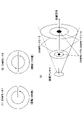
- FIG. 2 shows an example of the phase distribution and signal intensity distribution of the OAM multiplex signal.
- the phase distributions of the signals of OAM mode 1 and OAM mode 2 as seen from the end face (propagation orthogonal plane) orthogonal to the propagation direction from the transmission side are represented by arrows.
- the beginning of the arrow is 0 degrees, the phase changes linearly and the end of the arrow is 360 degrees. That is, the signal in the OAM mode n propagates while the phase rotates n times (n ⁇ 360 degrees) in the propagation orthogonal plane.
- the arrows in the phase distribution of the signals in OAM modes -1 and -2 are in the opposite direction.
- the signal of each OAM mode has a different signal strength distribution and the position where the signal strength is maximized for each OAM mode.
- the intensity distributions of the same OAM modes with different signs are the same.
- the higher the OAM mode the farther the position where the signal strength is maximized from the propagation axis (Non-Patent Document 2).
- the one with a larger value in the OAM mode is referred to as a higher-order mode.
- the signal in OAM mode 3 is a higher-order mode than the signals in OAM mode 0, OAM mode 1, and OAM mode 2.
- FIG. 2 (3) shows the position where the signal strength becomes maximum in each OAM mode by an annulus, but the position where the signal strength becomes maximum becomes farther from the central axis and the propagation distance becomes higher as the OAM mode becomes higher. Accordingly, the beam diameter of the OAM mode multiplex signal is widened, and the annulus indicating the position where the signal strength is maximized becomes large in each OAM mode.
- a transmission device and a reception device using UCA enable large-capacity communication, but it is desired to support mobile communication in the future.
- the axis between the transmitting antenna of the transmitting device (base station) and the receiving antenna of the receiving device (mobile terminal) shifts, resulting in interference between OAM modes in the receiving device. May occur.
- the receiving device feeds back the OAM mode having a low interference amount to the transmitting device, so that the transmitting device transmits data using only the OAM mode having a low interference amount.
- FIG. 3 shows a configuration example of the wireless communication system according to the present embodiment.
- the wireless communication system according to the present embodiment includes a transmitting device 100 and a receiving device 200.
- the transmitting device 100 and the receiving device 200 are provided with a UCA and a butler circuit, respectively.
- the transmitting device 100 multiplexes and transmits one or more OAM mode signals
- the receiving device 200 receives the one or more OAM mode multiplexed signals transmitted from the transmitting device 100. , Separate the signal of each OAM mode.
- the transmitting device 100 is a non-moving base station and the receiving device 200 is a mobile terminal.
- the transmitting device 100 and the receiving device 200 may both be base stations that do not move, or the transmitting device 100 and the receiving device 200 may both be mobile terminals.
- the transmitting device 100 transmits a signal (eg, an orthogonal signal sequence) to the receiving device 200 in a plurality of candidate OAM modes used in data communication.
- a signal eg, an orthogonal signal sequence
- the receiving device 200 calculates the interference amount of the signal of each OAM mode, and selects one or more OAM modes in which the interference amount is lower than a predetermined threshold value.
- the receiving device 200 feeds back the identification information (index) of the OAM mode selected in S102 to the transmitting device 100.
- Communication for control such as transmission / reception of feedback may be performed using UCA by using one OAM mode, or each of the transmitting device 100 and the receiving device 200 is controlled separately from the UCA. It may be possible to provide an antenna for communication and use the antenna.
- the transmitting device 100 transmits data using one or more OAM modes fed back from the receiving device 200 in S103. Since the receiving device 200 receives the OAM mode signal having a small interference amount, the receiving device 200 receives the desired data without performing the signal separation processing in the digital signal processing (or reducing the calculation amount related to the signal separation processing). be able to.
- the processes of S101 to S103 may be executed at a predetermined cycle or at a predetermined timing. Further, the processes S101 to S103 may be executed when the receiving device 200 requests the transmitting device 100.
- the receiving device 200 periodically reports the reception quality to the transmitting device 100, and when the transmitting device 100 detects that the receiving quality is lower than the threshold value. , S101 to S103 may be executed.
- interference amount is used as an index for selecting the OAM mode. That is, an index regarding the poor quality of the signal in each OAM mode is used.
- the OAM mode to be used may be selected by using an index (eg, reception quality) of the signal quality of each OAM mode instead of the “interference amount”. In this case, for example, the OAM mode in which the reception quality is larger than the threshold value is selected.
- index value to be compared with the threshold value such as “interference amount” and “reception quality” may be referred to as “determination value regarding interference between OAM modes”.
- a threshold value that satisfies the required reception quality without performing signal separation processing in digital signal processing in the receiving device 200 is determined by experiment or simulation. Further, a threshold value that satisfies the required reception quality in the signal separation processing equal to or less than the upper limit of the calculation amount of the signal separation processing in the digital signal processing may be determined by experiment or simulation.
- Example 1 First, Example 1 will be described.
- the transmitting device 100 transmits signals to the receiving device 200 separately (at different timings, not simultaneously) in each of the plurality of OAM modes that are candidates for use. For example, assuming that there are four OAM modes of 1, -1, 2, and -2, the transmission device 100 has an OAM mode 1 signal, an OAM mode-1 signal, an OAM mode 2 signal, and an OAM. Each of the mode-2 signals is transmitted to the receiving device 200.
- the butler circuit in the receiving device 200 has a plurality of output ports, and one output port corresponds to one OAM mode.
- the signal of OAM mode 1 (the signal transmitted by the radio wave of OAM mode 1) from the output port # 1 of the butler circuit in the receiving device 200 in the absence of interference. Is output, the OAM mode-1 signal is output from the output port # 2, the OAM mode 2 signal is output from the output port # 3, and the OAM mode-2 signal is output from the output port # 4. do.
- the OAM mode 1 signal will be output from output ports other than output port # 1.
- the interference amount of a certain OAM mode is the sum of the signal strengths (received power) output from one or more output ports other than the output port corresponding to the OAM mode in the butler circuit of the receiving device 200. do.
- the receiving device 200 compares the interference amount of each OAM mode measured (calculated) as described above with the threshold value, and selects an OAM mode that is less than the threshold value (may be less than or equal to the threshold value).
- the transmitting device 100 transmits a signal obtained by multiplexing a plurality of OAM mode signals that are candidates for use to the receiving device 200. For example, assuming that there are four OAM modes of 1, -1, 2, and -2, the transmission device 100 has an OAM mode 1 signal, an OAM mode-1 signal, an OAM mode 2 signal, and an OAM. A signal obtained by multiplexing the mode-2 signal is transmitted to the receiving device 200.
- the signal of OAM mode 1 is output from the output port # 1 of the butler circuit in the receiving device 200, and the signal of OAM mode 1 is output from the output port # 2 in the state where there is no interference.
- the signal is output, the OAM mode 2 signal is output from the output port # 3, and the OAM mode-2 signal is output from the output port # 4.
- a signal in which multiple OAM mode signals are mixed is output from each output port. For example, a signal including an OAM mode 1 signal and an OMA mode 2 signal is output from the output port # 1.
- Example 2 in S102, the reception quality of the signal output from each output port of the butler circuit of the receiving device 200 is measured, the measured reception quality is compared with the threshold value, and the value is larger than the threshold value (even if it is equal to or higher than the threshold value). Good) Select OAM mode.
- the above reception quality is, for example, SNR (signal-to-noise ratio).
- SNR signal-to-noise ratio
- the transmitting device 100 transmits a signal obtained by multiplexing a plurality of OAM mode signals that are candidates for use to the receiving device 200.
- the transmission device 100 has an OAM mode 1 signal, an OAM mode-1 signal, an OAM mode 2 signal, and an OAM.
- a signal obtained by multiplexing the mode-2 signal is transmitted to the receiving device 200.
- the OAM mode 1 signal, the OAM mode-1 signal, the OAM mode 2 signal, and the OAM mode-2 signal transmit different known bit strings.
- the signal of OAM mode 1 is output from the output port # 1 of the butler circuit in the receiving device 200, and the signal of OAM mode 1 is output from the output port # 2 in the state where there is no interference.
- the signal is output, the OAM mode 2 signal is output from the output port # 3, and the OAM mode-2 signal is output from the output port # 4. If there is no interference, by demodulating the signal output from each output port, the bit string transmitted in each OAM mode can be obtained without error.
- Example 3 in S102, the BER (bit error rate) in the bit string obtained by demodulating the signal output from each output port of the butler circuit of the receiving device 200 is calculated, and this is used as the interference amount. ..
- the receiving device 200 compares the interference amount of each OAM mode measured (calculated) as described above with the threshold value, and selects an OAM mode that is less than the threshold value (may be less than or equal to the threshold value).
- FIG. 5 is a diagram showing a configuration example of the transmission device 100 according to the present embodiment.
- the transmission device 100 includes a UCA 110, an OAM mode generation unit 120, a signal processing unit 130, and a control unit 140.
- the "UCA 110, OAM mode generation unit 120, signal processing unit 130" may be referred to as a transmission unit.
- the signal processing unit 130 generates a digital signal to be transmitted on a carrier from the input data, converts the digital signal into an analog signal (digital-analog conversion), and converts the frequency of the analog signal into the frequency band of the carrier (eg, the frequency band of the carrier). : 28GHz band).
- the signal processing unit 130 inputs the generated analog signal to the OAM mode generation unit 120 (butler circuit).
- control unit 140 instructs the signal processing unit 130 to receive feedback from the receiving device 200 and generate a signal to be transmitted in the OAM mode specified by the feedback.
- the signal processing unit 130 when the signal processing unit 130 receives an instruction from the control unit 140 to generate OAM mode 1 and OAM mode 2 signals, the signal processing unit 130 generates those signals and transmits the OAM mode 1 signal (transmitted by the OAM mode 1 radio wave). (Signal to be transmitted) is input to the input port corresponding to OAM mode 1 of the OAM mode generation unit 120 (Butler circuit), and the OAM mode 2 signal (signal transmitted by the radio wave of OAM mode 2) is input to the OAM mode generation unit 120. Input to the input port corresponding to OAM mode 2 of (Butler circuit).
- the OAM mode generation unit 120 is a butler circuit.
- FIG. 6 shows an example of a connection configuration between the OAM mode generator 120 (butler circuit) and the UCA 110.
- the UCA110 in the example shown in FIG. 6 is an antenna in which eight antenna elements # 1 to # 8 are arranged in a circular shape.
- FIG. 6 shows that the Butler circuit has N input ports. Basically, the number of output ports is the maximum number of N, and when there are eight output ports as in the example of FIG. 6, the maximum number of N is eight.
- the "port" may be referred to as a "terminal”.
- the number of antenna elements is eight. There may be a plurality of UCA and Butler circuits, respectively.
- the number of antenna elements of the UCA110 may be more than eight or less.
- FIG. 6 shows, as an example, that a signal to be transmitted in OAM mode 1 is input to input port A, and a signal to be transmitted in OAM mode -1 is input to input port B.
- the input ports other than the input port A and the input port B correspond to the OAM modes other than the OAM modes 1 and -1.
- a signal with a phase difference of 45 ° (360 ° / 8) counterclockwise is output from each output port for input from input port A, and each output is output for input from input port B.
- a signal with a phase difference of -45 ° counterclockwise is output from the port. That is, when both the input port A and the input port B have inputs, a signal obtained by combining (multiplexing) two signals having different phases is output from each output port.
- each antenna element of the UCA 110 outputs a signal obtained by combining two signals having the following phases. To.
- the output port J of the OAM mode generator 120 (Butler circuit) is connected to the antenna element # 1 of the UCA 110, the output port I is connected to the antenna element # 2 of the UCA 110, and the output port H is ,
- the output port G is connected to the antenna element # 4 of the UCA 110, the output port F is connected to the antenna element # 5 of the UCA 110, and the output port E is the antenna element of the UCA 110.
- the output port D is connected to the antenna element # 7 of the UCA 110, and the output port C is connected to the antenna element # 8 of the UCA 110.
- FIG. 6 shows the connection of only the output port J.
- the signal output from each output port is supplied to the connected antenna element and output as a radio wave from the antenna element.
- control unit 140 When the control unit 140 detects a trigger (eg, arrival of a cycle, request from the receiving device 200, etc.) that executes the processing of S101 to S103 shown in FIG. 4, signal processing is performed so as to transmit a plurality of OAM mode signals. Instruct to unit 130. As a result, the signal of S101 is transmitted.
- a trigger eg, arrival of a cycle, request from the receiving device 200, etc.
- control unit 120 Upon receiving the feedback of S103, the control unit 120 instructs the signal processing unit 130 to input the OAM mode signal instructed by the feedback to the corresponding input port of the OAM mode generation unit 120 (butler circuit). ..
- FIG. 7 is a diagram showing a configuration example of the receiving device 200 according to the present embodiment.
- the receiving device 200 includes a UCA 210, an OAM mode separating unit 220, a signal processing unit 230, and a control unit 240.
- the "UCA210, OAM mode separation unit 220, signal processing unit 230" may be referred to as a receiving unit.
- the OAM mode separation unit 220 has a butler circuit. Further, the OAM mode separation unit 220 includes a measurement unit 221 for measuring the signal strength (or SNR) output from each output port of the butler circuit.
- the measuring unit 221 measures the signal strength (or SNR) output from each output port, notifies the control unit 240 of the measurement result, and the control unit 240 controls each OAM mode. Calculate the amount of interference (or reception quality). The control unit 240 selects the OAM mode based on the interference amount (or reception quality) of each OAM mode, and feeds back the selected OAM mode to the transmission device 100.
- FIG. 8 shows an example of a connection configuration between the OAM mode separation unit 220 (butler circuit) and the UCA 210.
- the UCA210 in the example shown in FIG. 8 is an antenna in which eight antenna elements # 1 to # 8 are arranged in a circular shape.
- the butler circuit shown in FIG. 8 corresponds to the one in which the input and the output of the butler circuit in the transmission device 100 are reversed.
- the butler circuit has N output ports. As shown in FIG. 7, it is an example that one UCA and one Butler circuit are provided, and the number of antenna elements is eight. There may be a plurality of UCA and Butler circuits, respectively. The number of antenna elements of the UC A210 may be more than eight or less.
- FIG. 8 shows, as an example, that the OAM mode 1 signal is output from the output port A and the OAM mode-1 signal is output from the output port B.
- the output ports other than the output port A and the output port B correspond to the OAM modes other than the OAM modes 1 and -1.
- Each antenna element of UCA210 and each input port of OAM mode separation unit 220 (Butler circuit) are connected as shown in the figure (for convenience of illustration, only # 7 is drawn with a connection line).
- a phase conversion or the like opposite to that of the butler circuit on the transmitting side is performed, so that an OAM mode signal corresponding to the output port is output from each output port.
- the signal processing unit 230 shown in FIG. 7 converts an analog signal received from the OAM mode separation unit 220 (Butler circuit) into a digital signal (analog-digital conversion), demodulates the signal, and generates data (bit string). Output. Further, the signal processing unit 230 performs signal separation processing by digital signal processing. If signal separation is not necessary, the signal separation process may not be performed.
- the signal processing unit 230 measures BER from a bit string obtained from a signal received from each output port of the OAM mode separation unit 220 (Butler circuit). Notify the control unit 240 of the measurement result.
- the control unit 240 instructs the signal processing unit 230 to receive only the OAM mode signal instructed to the transmission device 100 in S103 of FIG. 4 from the corresponding output port of the OAM mode separation unit 220 (butler circuit). ..
- the signal processing unit 230 performs demodulation processing and the like using the signal received from the output port.
- the signal having the OAM mode transmitted from the UCA of the transmitting device 100 has a place where the strength becomes stronger and a place where the strength becomes weaker on the end face on the receiving side. It depends on the distance between the transmitting device 100 and the receiving device 200. Also, this location is different for each OAM mode. That is, the OAM beam transmitted from the UCA of the transmitting device 100 (the beam in the OAM mode transmitted from the UCA) has a weakened or strong received power depending on the distance between the transmitting device 100 and the receiving device 200. There is a place to do it, which is different for each OAM mode.
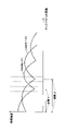
- FIG. 9 shows an example of the relationship between the distance from the UCA of the transmitting device 100 to the receiving device 200 and the receiving strength.
- the horizontal axis of FIG. 9 shows the distance from the UCA of the transmitting device 100 to the receiving device 200, and the vertical axis shows the receiving intensity at the position of the receiving device 200.
- the above distance is, for example, a distance in the direction perpendicular to the plane of the UCA.
- the reception intensity of the OAM mode 1 is weakened at the location of the distance 1
- the reception intensity of the OAM mode 2 is weakened at the location of the distance 2.
- "weak" signal strength (reception strength) at a certain place (position) may mean that the received power is lower than a certain threshold value, or it may be at another place (position). ) May be lower than the received power.
- "strong" signal strength (reception strength) at a certain place (position) may mean that the received power is higher than a certain threshold value or higher than the received power at another place (position). It may also be that the received power is high.
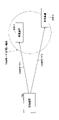
- FIG. 10 is a diagram showing a two-dimensional situation when the transmitting device 100, the receiving device 200-1 and the receiving device 200-2 are viewed from the sky.
- the UCA 110 of the transmitting device 100 is located on the rooftop of a building or the like, and the antenna is installed in a direction in which radio waves reach the ground side.
- the part (location) of the dotted line indicated by A is the location where the strength of the signal of OAM mode 1 transmitted from the transmission device 100 is weakened.
- the place where the signal strength of the OAM mode 1 is weakened is indicated by a circle.
- the receiving device 200-2 is located in a place where the strength of the signal of the OAM mode 1 transmitted from the transmitting device 100 is weakened. Further, the receiving device 200-1 is located at a place where the strength of the signal of the OAM mode 1 transmitted from the transmitting device 100 becomes strong.
- the control unit 140 of the transmitting device 100 grasps the positions of the receiving device 200-1 and the receiving device 200-2, the situation shown in FIG. 10 (the receiving device 200-1 has a reception intensity of OAM mode 1). Strong, the receiving device 200-2 has a weak reception strength in OAM mode 1).
- the transmitting device 100 transmits a signal from the UCA 110 to the receiving device 200-1 in the OAM mode 1, and is weak at another OAM mode (for example, the position of the receiving device 200-1).
- the signal to the receiving device 200-2 is transmitted in the mode) in which the signal becomes stronger at the position of the receiving device 200-2.
- the receiving device 200-1 can receive the OAM mode 1 signal transmitted from the transmitting device 100 without interference, and the receiving device 200-2 receives the signal of another mode transmitted from the transmitting device 100 without interference. can.
- each receiving device 200 feeds back the OAM mode having a small amount of interference (or having good reception quality or high receiving power) to the transmitting device 100 in S103.
- the transmitting device 100 grasps, for example, that the OAM mode 1 has good reception quality with respect to the receiving device 200-1 and the OAM mode 2 has good receiving quality with respect to the receiving device 200-2, the transmitting device 200-1 has a good reception quality.
- OAM mode 1 a signal is transmitted to the receiver 200-2, and a signal is transmitted to the receiving device 200-2 in OAM mode 2.
- the transmitting device 100 transmits all the signals of the OAM mode that can be transmitted by itself, and each receiving device 200 sets the receiving intensity (reception power, reception quality, etc.) for each OAM mode to the transmitting device 100. You may give feedback to.
- the transmitting device 100 transmits a signal to the receiving device 200-2 in the OAM mode in which the receiving device 200-1 has a weak receiving strength, and the receiving device 100 has a weak receiving strength to the receiving device 200-2.
- a signal is transmitted to the receiving device 200-1 in OAM mode.
- the signal transmitted to a certain receiving device can reduce the interference with another receiving device.
- the difference in the distribution of the signal strength (power) depending on the OAM mode and the difference in the distribution of the signal strength (power) depending on the distance described with reference to FIGS. 2 (3) and 9 depend on the size of the UCA of the transmission device 100. Will also be different.
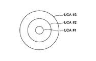
- the transmission device 100 includes UCA # 1 to # 3 having a plurality of different diameters, as shown in FIG.
- the OAM mode is from the UCA having a diameter at which the signal in the OAM mode is weakened at the position of the receiving device 200-x.
- the signal to the receiving device 200-y is transmitted, and the signal to the receiving device 200-x in the OAM mode is transmitted from the UCA having a diameter at which the signal in the OAM mode becomes weak at the position of the receiving device 200-y.
- Such control is also possible by the feedback control described above.
- the OAM mode when the signal of OAM mode 1 is transmitted from UCA # 2 among UCA # 1 to # 3 of the transmission device 100, the OAM mode is located at the circular location shown by A in FIG. It is assumed that the reception strength of 1 becomes weak. Further, for example, when a signal of OAM mode 2 is transmitted from UCA # 1, it is assumed that the signal strength of OAM mode 2 is weakened at the location of the receiving device 200-1.
- the transmitting device 100 transmits a signal from UCA # 2 to the receiving device 200-1 in OAM mode 1 based on the instruction of the control unit 140, and from UCA # 1 to the receiving device 200-2 in OAM mode 2.
- Send a signal
- the receiving device 200-1 can receive the OAM mode 1 signal transmitted from the transmitting device 100 with low interference, and the receiving device 200-2 lowers the OAM mode 2 signal transmitted from the transmitting device 100. Can be received by interference.
- the OAM mode used for transmission to the receiving device 200 has less interference with other receiving devices by using the characteristics that the intensity of the OAM differs depending on the mode and the diameter of the UCA of the OAM antenna.
- the OAM mode for transmitting a signal to a certain receiving device 200 it is preferable, but not essential, to select an OAM mode that becomes stronger at the position of the receiving device 200.
- the OAM mode may be selected according to the signal processing capability (interference elimination capability) of the receiving device 200.
- the receiving device 200-1 has a low signal processing capacity and requires quick processing such as real time processing, and the receiving device 200-2 is more than the receiving device 200-1. It is assumed that the signal processing capacity is high, the signal processing for interference elimination can be taken time, and the request for real time is small.
- the transmitting device 100 acquires the capability information of each receiving device as described above in advance. In the above case, the transmitting device 100 transmits a signal to the receiving device 200-2 using the OAM mode in which the signal is weakened at the position of the receiving device 200-1 based on the control by the control unit 140, so that the receiving device 200 Prevent the signal to -2 from reaching the receiving device 200-1 as interference.
- the transmitting device 100 transmits a signal to the receiving device 200-1 using the OAM mode in which the signal becomes stronger at the position of the receiving device 200-1.
- the receiving device 200-2 causes interference due to the OAM mode signal transmitted to the receiving device 200-1, but the receiving device 200-2 uses a conventional interference removing method such as an overloaded MIMO interference removing method. It can be used to acquire only the signal to the receiving device 200-2 itself.
- the receiving device 200-1 since the receiving device 200-1 has less interference from the OAM mode transmitted to the receiving device 200-2, the signal to the receiving device 200-1 itself can be acquired without performing the interference removing process.
- a wireless communication system including a transmitting device and a receiving device.
- the transmitting device transmits a plurality of OAM mode signals
- the transmission device transmits a plurality of OAM mode signals.
- the receiving device receives the signals of the plurality of OAM modes, calculates the determination value regarding the interference between the OAM modes for each OAM mode, and compares the determination value with the threshold value to obtain the plurality of OAM modes.
- One or more OAM modes are selected from among them, and the selected one or more OAM modes are notified to the transmission device.
- a wireless communication system in which the transmitting device transmits data to the receiving device using one or more OAM modes notified from the receiving device.
- (Section 2) Periodically, at predetermined timings, or based on requests from the receiver to the transmitter.
- the wireless communication system according to item 1 wherein the transmitting device transmits a plurality of OAM mode signals, and the receiving device selects one or more OAM modes based on the determination value.
- the wireless communication system includes a first receiving device and a second receiving device, and the transmitting device receives an OAM mode signal in which the receiving intensity at the position of the first receiving device is weakened.
- the wireless communication system according to the first or second item, which transmits to the second receiving device located at a position different from the existing position of the device.
- the transmitting device in a wireless communication system including a transmitting device and a receiving device.
- a transmitter that transmits a plurality of OAM mode signals to the receiver The transmitting unit is requested to receive the identification information of one or more OAM modes selected based on the reception of the signals of the plurality of OAM modes from the receiving device and transmit the data using the one or more OAM modes.
- the receiving device in a wireless communication system including a transmitting device and a receiving device.
- a receiver that receives a plurality of OAM mode signals from the transmitter, Based on the signals of the plurality of OAM modes, a determination value regarding interference between OAM modes for each OAM mode is calculated, and by comparing the determination value with the threshold value, one or more of the plurality of OAM modes are selected.
- a receiving device including a control unit that selects an OAM mode and notifies the transmitting device of one or more selected OAM modes. (Section 6)
- the receiving unit includes a butler circuit, and when a signal of a specific OAM mode is received, measures the signal strength of the signal output from an output port other than the output port corresponding to the specific OAM mode in the butler circuit. death, Item 5.
- the receiving device wherein the control unit uses the signal strength as a determination value for the specific OAM mode.
- the receiving unit includes a butler circuit, and calculates an error rate of data obtained by demodulating each OAM mode signal output from the butler circuit.
- the receiving device according to item 5, wherein the control unit uses the error rate as the determination value for each OAM mode.
- the receiving device according to any one of Items 5 to 7, wherein the control unit selects each OAM mode having a determination value indicating that the interference between OAM modes is smaller than the threshold value.
- a communication method in a wireless communication system including a transmitting device and a receiving device.
- the transmitting device transmits a plurality of OAM mode signals, and the transmission device transmits a plurality of OAM mode signals.
- the receiving device receives the signals of the plurality of OAM modes, calculates the determination value regarding the interference between the OAM modes for each OAM mode, and compares the determination value with the threshold value to obtain the plurality of OAM modes.
- One or more OAM modes are selected from among them, and the selected one or more OAM modes are notified to the transmission device.
- a communication method in which the transmitting device transmits data to the receiving device using one or more OAM modes notified by the receiving device.
Landscapes
- Engineering & Computer Science (AREA)
- Computer Networks & Wireless Communication (AREA)
- Signal Processing (AREA)
- Mobile Radio Communication Systems (AREA)
Abstract
送信装置と受信装置とを備える無線通信システムであって、前記送信装置が、複数のOAMモードの信号を送信し、前記受信装置が、前記複数のOAMモードの信号を受信し、各OAMモードについてのOAMモード間干渉に関する判定値を算出し、当該判定値と閾値とを比較することにより、前記複数のOAMモードの中から1以上のOAMモードを選択し、選択した1以上のOAMモードを前記送信装置に通知し、前記送信装置が、前記受信装置から通知された1以上のOAMモードを用いて前記受信装置にデータを送信する。
Description
本発明は、電磁波の軌道角運動量(Orbital Angular Momentum:OAM)を用いて無線信号を空間多重伝送する技術に関連するものである。
近年、伝送容量向上のため、OAMを用いた無線信号の空間多重伝送技術の検討が進められている。(例えば、非特許文献1)。OAMを持つ電磁波は、伝搬軸を中心に伝搬方向にそって等位相面がらせん状に分布する。異なるOAMモードを持ち、同一方向に伝搬する電磁波は、回転軸方向において空間位相分布が直交するため、異なる信号系列で変調された各OAMモードの信号を受信装置において分離することにより、信号を多重伝送することが可能である。
このOAM多重技術を用いた無線通信システムでは、複数のアンテナ素子を等間隔に円形配置した等間隔円形アレーアンテナ(以下、UCA(Uniform Circular Array)と称する。)を用い、複数のOAMモードを生成・合成して送信することにより、異なる信号系列の空間多重伝送を実現できる(例えば、非特許文献2)。複数のOAMモードの信号生成及び信号分離には、例えば、バトラー回路(バトラーマトリクス回路)が使用される。
J. Wang et al., "Terabit free-space data transmission employing orbital angular momentum multiplexing, "Nature Photonics, Vol.6, pp.488-496, July 2012.
Y. Yan et al., "High-capacity millimeter-wave communications with orbital angular momentum multiplexing, "Nature Commun., vol.5, p.4876, Sep. 2014.
上記のように、UCAを用いた送信装置と受信装置により、大容量の通信が可能になるが、今後は、移動通信への対応が望まれている。
しかし、UCAを用いた従来の無線伝送技術では、複数のOAMモードの信号をモード間の干渉なく分離するために、送信アンテナと受信アンテナを正面で対向する位置に設置する必要があり、軸合わせが必要である。例えば受信装置として移動端末を使用した場合に、送信装置(基地局)の送信アンテナと受信装置(移動端末)の受信アンテナとの間の軸がずれる結果、受信装置においてOAMモード間で干渉が生じる場合がある。
受信装置においてOAMモード間干渉が生じると、干渉した信号を分離するための演算が必要となる。信号分離のための演算量は、帯域幅に比例して増加するため、広い帯域幅を使うほど演算量が増大し、広帯域化が困難となる。
本発明は上記の点に鑑みてなされたものであり、UCAを用いた無線伝送技術において、受信側におけるOAMモード間干渉を低減することを可能とする技術を提供することを目的とする。
開示の技術によれば、送信装置と受信装置とを備える無線通信システムであって、
前記送信装置が、複数のOAMモードの信号を送信し、
前記受信装置が、前記複数のOAMモードの信号を受信し、各OAMモードについてのOAMモード間干渉に関する判定値を算出し、当該判定値と閾値とを比較することにより、前記複数のOAMモードの中から1以上のOAMモードを選択し、選択した1以上のOAMモードを前記送信装置に通知し、
前記送信装置が、前記受信装置から通知された1以上のOAMモードを用いて前記受信装置にデータを送信する
無線通信システムが提供される。
前記送信装置が、複数のOAMモードの信号を送信し、
前記受信装置が、前記複数のOAMモードの信号を受信し、各OAMモードについてのOAMモード間干渉に関する判定値を算出し、当該判定値と閾値とを比較することにより、前記複数のOAMモードの中から1以上のOAMモードを選択し、選択した1以上のOAMモードを前記送信装置に通知し、
前記送信装置が、前記受信装置から通知された1以上のOAMモードを用いて前記受信装置にデータを送信する
無線通信システムが提供される。
開示の技術によれば、UCAを用いた無線伝送技術において、受信側におけるOAMモード間干渉を低減することを可能とする技術が提供される。
以下、図面を参照して本発明の実施の形態(本実施の形態)を説明する。以下で説明する実施の形態は一例に過ぎず、本発明が適用される実施の形態は、以下の実施の形態に限られるわけではない。
(基本的な動作例)
まず、本実施の形態における送信装置及び受信装置において使用するUCAに係る基本的な設定・動作例について説明する。
まず、本実施の形態における送信装置及び受信装置において使用するUCAに係る基本的な設定・動作例について説明する。
図1は、OAMモードの信号を生成するためのUCAの位相設定例を示す。図1に示すUCAは、8つのアンテナ素子からなるUCAである。
図1において、送信側におけるOAMモード0,1,2,3,…の信号は、UCAの各アンテナ素子(●で示す)に供給される信号の位相差により生成される。すなわち、OAMモードnの信号は、位相がn回転(n×360度)になるように各アンテナ素子に供給する信号の位相を設定して生成する。例えば、図1に示すようにUCAがm=8個のアンテナ素子で構成される場合で、OAMモードn=2の信号を生成する場合は、図1(3)に示すように、位相が2回転するように、各アンテナ素子に反時計回りに360n/m=90度の位相差(0度,90度,180度,270度,0度,90度,180度,270度)を設定する。
なお、OAMモードnの信号に対して位相の回転方向を逆にした信号をOAMモード-nとする。例えば、正のOAMモードの信号の位相の回転方向を反時計回りとし、負のOAMモードの信号の位相の回転方向を時計回りとする。
異なる信号系列を異なるOAMモードの信号として生成し、生成した信号を同時に送信することで、空間多重による無線通信を行うことができる。送信側では、各OAMモードで伝送する信号を予め生成・合成し、単一UCAで各OAMモードの合成信号を送信してもよいし、複数のUCAを用いて、OAMモード毎に異なるUCAで各OAMモードの信号を送信してもよい。
受信側でOAM多重信号を分離するためには、受信側のUCAの各アンテナ素子の位相を、送信側のアンテナ素子の位相と逆方向になるように設定すればよい。
ただし、送信アンテナと受信アンテナとの間の軸ずれ等により、OAMモード間で干渉が生じた場合、チャネル等化処理や逐次干渉除去処理等のデジタル信号処理により、干渉で混ざったOAMモード間の信号を分離することが必要になる。なお、OAMモード間の干渉とは、例えば、送信装置からOAMモード1で送信した信号が、受信側でOAMモード2の信号として出力されるといったことである。
図2は、OAM多重信号の位相分布と信号強度分布の例を示す。図2(1),(2)において、送信側から伝搬方向に直交する端面(伝搬直交平面)で見た、OAMモード1とOAMモード2の信号の位相分布を矢印で表す。矢印の始めは0度であり、位相が線形に変化して矢印の終わりは360度である。すなわち、OAMモードnの信号は、伝搬直交平面において、位相がn回転(n×360度)しながら伝搬する。なお、OAMモード-1,-2の信号の位相分布の矢印は逆向きになる。
各OAMモードの信号は、OAMモード毎に信号強度分布と信号強度が最大になる位置が異なる。ただし、符号が異なる同じOAMモードの強度分布は同じである。具体的には、OAMモードが高次になるほど、信号強度が最大になる位置が伝搬軸から遠くなる(非特許文献2)。ここで、OAMモードの値が大きい方を高次モードと称する。例えば、OAMモード3の信号は、OAMモード0、OAMモード1、OAMモード2の信号より、高次モードである。
図2(3)は、OAMモードごとに信号強度が最大になる位置を円環で示すが、OAMモードが高次になるほど信号強度が最大になる位置が中心軸から遠くなり、かつ伝搬距離に応じてOAMモード多重信号のビーム径が広がり、OAMモードごとに信号強度が最大になる位置を示す円環が大きくなる。
(本発明の実施の形態の概要)
前述したとおり、UCAを用いた送信装置と受信装置により、大容量の通信が可能になるが、今後は、移動通信への対応が望まれている。しかし、例えば受信装置として移動端末を使用した場合に、送信装置(基地局)の送信アンテナと受信装置(移動端末)の受信アンテナとの間の軸がずれる結果、受信装置においてOAMモード間で干渉が生じる場合がある。
前述したとおり、UCAを用いた送信装置と受信装置により、大容量の通信が可能になるが、今後は、移動通信への対応が望まれている。しかし、例えば受信装置として移動端末を使用した場合に、送信装置(基地局)の送信アンテナと受信装置(移動端末)の受信アンテナとの間の軸がずれる結果、受信装置においてOAMモード間で干渉が生じる場合がある。
受信装置においてOAMモード間干渉が生じると、前述したように、デジタル信号処理により干渉した信号を分離するための演算が必要となる。このための演算量は、帯域幅に比例して増加するため、広い帯域幅を使うほど演算量が多くなる。受信装置として移動端末を使用することを想定した場合、能力が限られている移動端末において、OAMモード間の信号分離のための演算量が増加することは望ましくない。
そこで、本実施の形態では、受信装置から送信装置に対して、干渉量の低いOAMモードをフィードバックすることで、送信装置は干渉量の低いOAMモードのみを使用してデータ送信を行う。これにより、受信装置におけるOAMモード間の信号分離のためのデジタル信号処理に係る演算量を低減する、あるいは、無くすことができる。その結果、広帯域化も可能となる。
以下、本実施の形態におけるシステム構成と、動作について詳細に説明する。
(システム構成)
図3に、本実施の形態における無線通信システムの構成例を示す。図3に示すように、本実施の形態における無線通信システムは、送信装置100と受信装置200を有する。
図3に、本実施の形態における無線通信システムの構成例を示す。図3に示すように、本実施の形態における無線通信システムは、送信装置100と受信装置200を有する。
送信装置100と受信装置200は、それぞれUCAとバトラー回路を備えている。所望データの送受信において、送信装置100は、1以上のOAMモードの信号を多重して送信し、受信装置200は、送信装置100から送信された1以上のOAMモードが多重された信号を受信し、各OAMモードの信号を分離する。
本実施の形態では、送信装置100は移動しない基地局であり、受信装置200は移動端末であることを想定している。ただし、このような想定は一例である。例えば、送信装置100と受信装置200が両方とも移動しない基地局であってもよいし、送信装置100と受信装置200が両方とも移動端末であってもよい。
(システムの動作例)
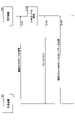
図4を参照して、本実施の形態における無線通信システムの動作例を説明する。
図4を参照して、本実施の形態における無線通信システムの動作例を説明する。
S101において、送信装置100は、データ通信において使用する候補となる複数のOAMモードで信号(例:直交信号系列)を受信装置200に送信する。
S102において、受信装置200は、各OAMモードの信号の干渉量を計算し、干渉量が所定の閾値よりも低い1以上のOAMモードを選択する。
S103において、受信装置200は、S102で選択したOAMモードの識別情報(インデックス)を送信装置100にフィードバックする。なお、フィードバックの送受信等の制御のための通信については、ある1つのOAMモードを使用することでUCAを用いて行ってもよいし、送信装置100と受信装置200のそれぞれにUCAとは別に制御通信用のアンテナを設け、そのアンテナを用いて行うこととしてもよい。
S104において、送信装置100は、S103で受信装置200からフィードバックされた1以上のOAMモードを使用してデータ送信を行う。受信装置200は、干渉量の小さいOAMモードの信号を受信するので、デジタル信号処理での信号分離処理を行うことなく(あるいは信号分離処理に係る演算量を低減して)所望のデータを受信することができる。
S101~S103の処理は、予め定めた周期で実行してもよいし、予め定めたタイミングで実行してもよい。また、S101~S103の処理は、受信装置200から送信装置100に対して要求があった場合に実行してもよい。
また、データ送受信の中で、受信装置200が送信装置100に対して受信品質の報告を周期的に行うこととし、送信装置100が、当該受信品質が閾値よりも低下したことを検知した場合に、S101~S103の処理を実行してもよい。
なお、上記の例では「干渉量」をOAMモード選択のための指標に使用している。つまり、各OAMモードの信号の品質の悪さに関する指標を使用している。しかし、これは一例である。「干渉量」ではなく、各OAMモードの信号の品質の良さの指標(例:受信品質)を用いて、使用するOAMモードを選択してもよい。この場合、例えば、受信品質が閾値よりも大きなOAMモードを選択することになる。
なお、「干渉量」や「受信品質」等、閾値と比較する対象となる指標値を「OAMモード間干渉に関する判定値」と呼んでもよい。
また、上記の各閾値については、例えば、受信装置200においてデジタル信号処理での信号分離処理を行わなくても要求受信品質を満たすような閾値を、実験あるいはシミュレーションで決定する。また、デジタル信号処理での信号分離処理の演算量の上限値以下の信号分離処理で要求受信品質を満たすような閾値を、実験あるいはシミュレーションで決定することとしてもよい。
S101の信号送信とS102のOAMモード選択には種々のバリエーションがある。以下、例1、例2、例3を説明する。なお、例1~3に限定されるわけではなく、これら以外の方法を用いてもよい。
<例1>
まず、例1を説明する。S101において、送信装置100は、使用候補になっている複数のOAMモードのそれぞれで別々に(同時ではなく異なるタイミングで)信号を受信装置200に送信する。例えば、複数のOAMモードが、1、-1、2、-2の4つであるとすると、送信装置100は、OAMモード1の信号、OAMモード-1の信号、OAMモード2の信号、OAMモード-2の信号のそれぞれを受信装置200に送信する。
まず、例1を説明する。S101において、送信装置100は、使用候補になっている複数のOAMモードのそれぞれで別々に(同時ではなく異なるタイミングで)信号を受信装置200に送信する。例えば、複数のOAMモードが、1、-1、2、-2の4つであるとすると、送信装置100は、OAMモード1の信号、OAMモード-1の信号、OAMモード2の信号、OAMモード-2の信号のそれぞれを受信装置200に送信する。
後述するように、受信装置200におけるバトラー回路は複数の出力ポートを有しており、1つの出力ポートが1つのOAMモードに対応している。
上記のように4つのOAMモードを使用する場合、干渉がない状態において、例えば、受信装置200におけるバトラー回路の出力ポート#1からOAMモード1の信号(OAMモード1の電波で伝送された信号)が出力され、出力ポート#2からOAMモード-1の信号が出力され、出力ポート#3からOAMモード2の信号が出力され、出力ポート#4からOAMモード-2の信号が出力されるものとする。
干渉がある場合、例えば、出力ポート#1以外の出力ポートからもOAMモード1の信号が出力されることになる。
そこで、例1では、あるOAMモードの干渉量を、受信装置200のバトラー回路における、当該OAMモードに対応する出力ポート以外の1以上の出力ポートから出力される信号強度(受信電力)の合計とする。
S102において、受信装置200は、上記のようにして測定(算出)した各OAMモードの干渉量を閾値と比較して、閾値未満(閾値以下でもよい)となるOAMモードを選択する。
<例2>
次に、例2を説明する。S101において、送信装置100は、使用候補になっている複数のOAMモードの信号を多重した信号を受信装置200に送信する。例えば、複数のOAMモードが、1、-1、2、-2の4つであるとすると、送信装置100は、OAMモード1の信号、OAMモード-1の信号、OAMモード2の信号、OAMモード-2の信号を多重した信号を受信装置200に送信する。
次に、例2を説明する。S101において、送信装置100は、使用候補になっている複数のOAMモードの信号を多重した信号を受信装置200に送信する。例えば、複数のOAMモードが、1、-1、2、-2の4つであるとすると、送信装置100は、OAMモード1の信号、OAMモード-1の信号、OAMモード2の信号、OAMモード-2の信号を多重した信号を受信装置200に送信する。
例1で使用したバトラー回路の例を用いて説明する。上記のように4つのOAMモードを使用する場合、干渉がない状態において、受信装置200におけるバトラー回路の出力ポート#1からOAMモード1の信号が出力され、出力ポート#2からOAMモード-1の信号が出力され、出力ポート#3からOAMモード2の信号が出力され、出力ポート#4からOAMモード-2の信号が出力される。
干渉がある場合、各出力ポートから、複数のOAMモードの信号が混在した信号が出力される。例えば、出力ポート#1から、OAMモード1の信号とOMAモード2の信号が含まれる信号が出力される。
そこで、例2では、S102において、受信装置200のバトラー回路の各出力ポートから出力される信号の受信品質を測定し、測定した受信品質と閾値とを比較して、閾値より大きい(閾値以上でもよい)OAMモードを選択する。
上記の受信品質は例えばSNR(信号対雑音比)である。例えば、OAMモード1に対応する出力ポート#1から出力される信号の中のOAMモード1の信号強度とOAMモード1以外の信号強度(雑音強度)を測定し、これらの比を計算することでOAMモード1のSNRを算出する。
<例3>
次に、例3を説明する。S101において、送信装置100は、使用候補になっている複数のOAMモードの信号を多重した信号を受信装置200に送信する。例えば、複数のOAMモードが、1、-1、2、-2の4つであるとすると、送信装置100は、OAMモード1の信号、OAMモード-1の信号、OAMモード2の信号、OAMモード-2の信号を多重した信号を受信装置200に送信する。例3では、OAMモード1の信号、OAMモード-1の信号、OAMモード2の信号、OAMモード-2の信号が、それぞれ異なる既知のビット列を伝送しているものとする。
次に、例3を説明する。S101において、送信装置100は、使用候補になっている複数のOAMモードの信号を多重した信号を受信装置200に送信する。例えば、複数のOAMモードが、1、-1、2、-2の4つであるとすると、送信装置100は、OAMモード1の信号、OAMモード-1の信号、OAMモード2の信号、OAMモード-2の信号を多重した信号を受信装置200に送信する。例3では、OAMモード1の信号、OAMモード-1の信号、OAMモード2の信号、OAMモード-2の信号が、それぞれ異なる既知のビット列を伝送しているものとする。
例1で使用したバトラー回路の例を用いて説明する。上記のように4つのOAMモードを使用する場合、干渉がない状態において、受信装置200におけるバトラー回路の出力ポート#1からOAMモード1の信号が出力され、出力ポート#2からOAMモード-1の信号が出力され、出力ポート#3からOAMモード2の信号が出力され、出力ポート#4からOAMモード-2の信号が出力される。干渉がなければ、それぞれの出力ポートから出力された信号を復調することで、各OAMモードにおいて送信されたビット列をエラー無しに得ることができるものとする。
干渉がある場合、各出力ポートから、複数のOAMモードの信号が混在した信号が出力されるため、復調して得たビット列にはエラー(既知のビットと異なるビット)が含まれる。
そこで、例3では、S102において、受信装置200のバトラー回路の各出力ポートから出力される信号を復調して得られたビット列におけるBER(bit error rate)を計算し、これを干渉量として使用する。
受信装置200は、上記のようにして測定(算出)した各OAMモードの干渉量を閾値と比較して、閾値未満(閾値以下でもよい)となるOAMモードを選択する。
(装置構成例)
次に、送信装置100と受信装置200の装置構成例を説明する。
次に、送信装置100と受信装置200の装置構成例を説明する。
<送信装置100>
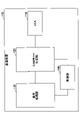
まず、送信装置100について説明する。図5は、本実施の形態における送信装置100の構成例を示す図である。図5に示すように、送信装置100は、UCA110、OAMモード生成部120、信号処理部130、制御部140を有する。なお、「UCA110、OAMモード生成部120、信号処理部130」を送信部と呼んでもよい。
まず、送信装置100について説明する。図5は、本実施の形態における送信装置100の構成例を示す図である。図5に示すように、送信装置100は、UCA110、OAMモード生成部120、信号処理部130、制御部140を有する。なお、「UCA110、OAMモード生成部120、信号処理部130」を送信部と呼んでもよい。
信号処理部130は、入力されたデータから、搬送波に乗せて送信するデジタル信号を生成し、デジタル信号をアナログ信号に変換(デジタル-アナログ変換)し、アナログ信号の周波数を搬送波の周波数帯(例:28GHz帯)に変換する。信号処理部130は、生成したアナログ信号をOAMモード生成部120(バトラー回路)に入力する。
本実施の形態では、制御部140が、受信装置200からフィードバックを受信し、そのフィードバックで指定されたOAMモードで送信する信号を生成するよう、信号処理部130に指示する。
例えば、信号処理部130は、制御部140からOAMモード1とOAMモード2の信号を生成するよう指示を受けると、それらの信号を生成し、OAMモード1の信号(OAMモード1の電波で伝送する信号)を、OAMモード生成部120(バトラー回路)のOAMモード1に対応する入力ポートに入力し、OAMモード2の信号(OAMモード2の電波で伝送する信号)を、OAMモード生成部120(バトラー回路)のOAMモード2に対応する入力ポートに入力する。
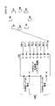
上記のとおり、OAMモード生成部120は、バトラー回路である。OAMモード生成部120(バトラー回路)と、UCA110との接続構成例を図6に示す。図6に示す例でのUCA110は、8個のアンテナ素子#1~#8が円形状に配置されたアンテナである。
また、図6は、バトラー回路が、N個の入力ポートを有していることを示している。基本的には、出力ポート数が、Nの最大数であり、図6の例のように、8個の出力ポートを有する場合、Nの最大数は8である。なお、「ポート」を「端子」と呼んでもよい。
図6のように、UCAとバトラー回路をそれぞれ1つずつ備えることや、アンテナ素子数が8個であること等は一例である。UCAとバトラー回路はそれぞれ複数であってもよい。UCA110のアンテナ素子数は、8個よりも多くてもよいし、少なくてもよい。
図6には、一例として、入力ポートAに、OAMモード1で送信しようとする信号が入力され、入力ポートBにOAMモード-1で送信しようとする信号が入力されることを示している。N個の入力ポートのうち、入力ポートAと入力ポートB以外の入力ポートは、OAMモード1と-1以外のOAMモードに対応している。
入力ポートAからの入力に対して、各出力ポートから反時計回りに45°(360°/8)ずつの位相差を持った信号が出力され、入力ポートBからの入力に対して、各出力ポートから反時計回りに-45°ずつの位相差を持った信号が出力される。つまり、入力ポートAと入力ポートBの両方に入力がある場合、各出力ポートから異なる位相を持つ2つの信号が合波(多重)された信号が出力される。
具体的には、UCA110において、便宜上、アンテナ素子#1を基準(位相0°)とすると、UCA110の各アンテナ素子からは、下記の位相を持った2つの信号が合波された信号が出力される。
アンテナ素子#1=(0°,0°)、アンテナ素子#2=(45°,-45°)、アンテナ素子#3=(90°,-90°)、アンテナ素子#4=(135°,-135°)、アンテナ素子#5=(180°,-180°)、アンテナ素子#6=(225°,-225°)、アンテナ素子#7=(270°,-270°)、アンテナ素子#8=(315°,-315°)。
図6の例では、OAMモード生成部120(バトラー回路)の出力ポートJが、UCA110のアンテナ素子#1に接続され、出力ポートIが、UCA110のアンテナ素子#2に接続され、出力ポートHが、UCA110のアンテナ素子#3に接続され、出力ポートGが、UCA110のアンテナ素子#4に接続され、出力ポートFが、UCA110のアンテナ素子#5に接続され、出力ポートEが、UCA110のアンテナ素子#6に接続され、出力ポートDが、UCA110のアンテナ素子#7に接続され、出力ポートCが、UCA110のアンテナ素子#8に接続される。なお、図示の便宜上、図6では、出力ポートJのみの接続を示している。各出力ポートから出力された信号は、接続されるアンテナ素子に供給され、アンテナ素子から電波として出力される。
制御部140は、図4に示したS101~S103の処理を実行するトリガ(例:周期の到来、受信装置200からの要求等)を検知すると、複数のOAMモードの信号送信を行うよう信号処理部130に対して指示する。これによりS101の信号送信がなされる。
制御部120は、S103のフィードバックを受信すると、信号処理部130に対して、フィードバックで指示されたOAMモードの信号をOAMモード生成部120(バトラー回路)の対応する入力ポートに入力するよう指示する。
<受信装置200>
次に、受信装置200について説明する。図7は、本実施の形態における受信装置200の構成例を示す図である。図7に示すように、受信装置200は、UCA210、OAMモード分離部220、信号処理部230、制御部240を有する。なお、「UCA210、OAMモード分離部220、信号処理部230」を受信部と呼んでもよい。
次に、受信装置200について説明する。図7は、本実施の形態における受信装置200の構成例を示す図である。図7に示すように、受信装置200は、UCA210、OAMモード分離部220、信号処理部230、制御部240を有する。なお、「UCA210、OAMモード分離部220、信号処理部230」を受信部と呼んでもよい。
OAMモード分離部220は、バトラー回路を有する。また、OAMモード分離部220は、バトラー回路の各出力ポートから出力される信号強度(又はSNR)を測定する測定部221を含む。
図4に示したS101、S102において、測定部221が各出力ポートから出力される信号強度(又はSNR)を測定し、測定結果を制御部240に通知し、制御部240は、各OAMモードの干渉量(又は受信品質)を算出する。制御部240は、各OAMモードの干渉量(又は受信品質)に基づいて、OAMモードを選択し、選択したOAMモードを送信装置100にフィードバックする。
OAMモード分離部220(バトラー回路)と、UCA210との接続構成例を図8に示す。図8に示す例でのUCA210は、8個のアンテナ素子#1~#8が円形状に配置されたアンテナである。
また、図8に示すバトラー回路は、送信装置100におけるバトラー回路の入力と出力を逆にしたものに相当する。
図8に示すように、当該バトラー回路はN個の出力ポートを有している。図7のように、UCAとバトラー回路をそれぞれ1つずつ備えることや、アンテナ素子数が8個であること等は一例である。UCAとバトラー回路はそれぞれ複数であってもよい。UCA210のアンテナ素子数は、8個よりも多くてもよいし、少なくてもよい。
図8は、一例として、出力ポートAからOAMモード1の信号が出力され、出力ポートBからOAMモード-1の信号が出力されることを示している。N個の出力ポートのうち、出力ポートAと出力ポートB以外の出力ポートは、OAMモード1と-1以外のOAMモードに対応している。
UCA210の各アンテナ素子とOAMモード分離部220(バトラー回路)の各入力ポートは図示のように接続される(図示の便宜上、#7のみ接続線を描いている)。バトラー回路内では、送信側のバトラー回路とは逆の位相変換等が行われることで、各出力ポートから、その出力ポートに対応したOAMモードの信号が出力される。
図7に示す信号処理部230は、OAMモード分離部220(バトラー回路)から受信したアナログ信号をデジタル信号に変換(アナログ-デジタル変換)し、復調を行って、データ(ビット列)を生成し、出力する。また、信号処理部230はデジタル信号処理による信号分離処理を行う。なお、信号分離の必要はない場合には、信号分離処理を行わなくてもよい。
前述した干渉量の測定において、BERを使用する場合には、信号処理部230は、OAMモード分離部220(バトラー回路)の各出力ポートから受信した信号から得られたビット列からBERを測定し、測定結果を制御部240に通知する。
制御部240は、図4のS103で送信装置100に対して指示したOAMモードの信号のみを、OAMモード分離部220(バトラー回路)の対応する出力ポートから受信するよう信号処理部230に指示する。信号処理部230は、当該出力ポートから受信する信号を用いて、復調処理等を行う。
(複数の受信装置200との通信について)
図2(3)に示したように、送信装置100のUCAから送信されたOAMモードを持つ信号は、受信側の端面において、その強度が強くなる場所と弱くなる場所があり、その場所は、送信装置100と受信装置200との間の距離により異なる。また、この場所はOAMモード毎に異なる。つまり、送信装置100のUCAから送信されるOAMビーム(UCAから送信されるOAMモードのビーム)は、送信装置100と受信装置200との間の距離に応じて、受信電力が弱くなったり強くなったりする場所があり、それはOAMモード毎に異なる。
図2(3)に示したように、送信装置100のUCAから送信されたOAMモードを持つ信号は、受信側の端面において、その強度が強くなる場所と弱くなる場所があり、その場所は、送信装置100と受信装置200との間の距離により異なる。また、この場所はOAMモード毎に異なる。つまり、送信装置100のUCAから送信されるOAMビーム(UCAから送信されるOAMモードのビーム)は、送信装置100と受信装置200との間の距離に応じて、受信電力が弱くなったり強くなったりする場所があり、それはOAMモード毎に異なる。
図9に、送信装置100のUCAから受信装置200までの距離と、受信強度との関係の例を示す。図9の横軸は、送信装置100のUCAから受信装置200までの距離を示し、縦軸は、受信装置200の位置における受信強度である。上記の距離は、例えば、UCAの面と垂直な方向の距離である。
図9に示す例では、距離1の場所でOAMモード1の受信強度が弱くなり、距離2の場所でOAMモード2の受信強度が弱くなる。なお、本実施の形態において、ある場所(位置)での信号の強度(受信強度)が「弱い」とは、ある閾値よりも受信電力が低いことであってもよいし、他の場所(位置)での受信電力よりも受信電力が低いことであってもよい。また、ある場所(位置)での信号の強度(受信強度)が「強い」とは、ある閾値よりも受信電力が高いことであってもよいし、他の場所(位置)での受信電力よりも受信電力が高いことであってもよい。
上記の特徴を用いて、送信装置100と複数の受信装置200との間で同時に通信を行うことができる。図10を参照して通信の例を説明する。
図10は、送信装置100と、受信装置200-1と、受信装置200-2とを上空から見た場合の2次元的な状況を示す図である。ここでは、送信装置100のUCA110は、ビルの屋上等にあり、地面側に電波が届くような向きにアンテナが設置されていることを想定している。
図10の例では、Aで示す点線の円の部分(場所)が、送信装置100から送信されるOAMモード1の信号の強度が弱くなる場所であるとする。なお、ここでは便宜上、OAMモード1の信号の強度が弱くなる場所を円形で示している。
図10に示すように、受信装置200-2は、送信装置100から送信されるOAMモード1の信号の強度が弱くなる場所に位置している。また、受信装置200-1は、送信装置100から送信されるOAMモード1の信号の強度が強くなる場所に位置している。
例えば、送信装置100の制御部140が、受信装置200-1と受信装置200-2それぞれの位置を把握することにより、図10に示す状況(受信装置200-1はOAMモード1の受信強度が強、受信装置200-2はOAMモード1の受信強度が弱)を把握する。
そして、制御部140の指示に基づいて、送信装置100は、UCA110からOAMモード1で受信装置200-1に対する信号を送信するとともに、他のOAMモード(例えば、受信装置200-1の位置で弱くなり、受信装置200-2の位置で強くなるモード)で、受信装置200-2に対する信号を送信する。受信装置200-1は、送信装置100から送信されたOAMモード1の信号を干渉無しに受信でき、受信装置200-2は、送信装置100から送信された他のモードの信号を干渉無しに受信できる。
上記の制御は、例えば、図4に示すフィードック制御を用いることにより行ってもよい。この場合、各受信装置200は、S103において、干渉量の小さい(あるいは、受信品質の良い、あるいは、受信電力の高い)OAMモードを送信装置100にフィードバックする。送信装置100は、例えば、OAMモード1が受信装置200-1に対して受信品質が良く、OAMモード2が受信装置200-2に対して受信品質が良いことを把握すると、受信装置200-1に対してOAMモード1で信号を送信し、受信装置200-2に対してOAMモード2で信号を送信する。
また、例えば、送信装置100が、自身が送信可能な全てのOAMモードの信号を送信し、各受信装置200が、OAMモード毎の受信強度(受信電力、受信品質等でもよい)を送信装置100にフィードバックしてもよい。この場合、送信装置100は、例えば、受信装置200-1に対して受信強度の弱いOAMモードで受信装置200-2に対して信号を送信し、受信装置200-2に対して受信強度の弱いOAMモードで受信装置200-1に対して信号を送信する。これにより、ある受信装置に送信する信号により、他の受信装置への干渉を低減できる。
図2(3)、図9を参照して説明した、OAMモードによる信号強度(電力)の分布の違いや、距離による信号強度(電力)の分布の違いは、送信装置100のUCAのサイズによっても違ってくる。
例えば、送信装置100が、図11に示すように、複数の異なる直径を持つUCA#1~#3を備えるものとする。この場合、送信装置100は、例えば、受信装置200-x及び受信装置200-yと通信を行う場合において、受信装置200-xの位置でOAMモードの信号が弱くなる直径のUCAから当該OAMモードで受信装置200-yに対する信号を送信し、受信装置200-yの位置でOAMモードの信号が弱くなる直径のUCAから当該OAMモードで受信装置200-xに対する信号を送信する。このような制御についても、前述したフィードバック制御により可能である。
例えば、図10に示す例において、送信装置100のUCA#1~#3のうち、UCA#2からOAMモード1の信号を送信した場合に、図10のAで示す円形上の場所でOAMモード1の受信強度が弱くなるとする。また、例えば、UCA#1からOAMモード2の信号を送信した場合に、受信装置200-1の場所でOAMモード2の信号強度が弱くなるとする。
この場合、送信装置100は、制御部140の指示に基づいて、UCA#2からOAMモード1で受信装置200-1に対する信号を送信し、UCA#1からOAMモード2で受信装置200-2に対する信号を送信する。これにより、受信装置200-1は、送信装置100から送信されたOAMモード1の信号を低い干渉で受信でき、受信装置200-2は、送信装置100から送信されたOAMモード2の信号を低い干渉で受信できる。
(受信装置200の能力に応じた処理)
上記のように、OAMの強度がモード毎に、かつ、OAMアンテナのUCAの直径により異なる特徴を用いて、受信装置200への送信に使用するOAMモードを、他の受信装置への干渉が少なくなるように選択する場合において、ある受信装置200に対する信号を送信するためのOAMモードとして、その受信装置200の位置で強くなるOAMモードを選択することが好ましいが必須ではない。受信装置200の信号処理能力(干渉除去能力)に応じて、OAMモードを選択してもよい。
上記のように、OAMの強度がモード毎に、かつ、OAMアンテナのUCAの直径により異なる特徴を用いて、受信装置200への送信に使用するOAMモードを、他の受信装置への干渉が少なくなるように選択する場合において、ある受信装置200に対する信号を送信するためのOAMモードとして、その受信装置200の位置で強くなるOAMモードを選択することが好ましいが必須ではない。受信装置200の信号処理能力(干渉除去能力)に応じて、OAMモードを選択してもよい。
例えば、図10に示したような状況において、受信装置200-1が、信号処理能力が低く、real time処理等の素早い処理が必要であり、受信装置200-2は、受信装置200-1より信号処理能力が高く、干渉除去の信号処理に時間を掛けることができ、real timeの要求が少ない場合を想定する。
送信装置100は、上記のような各受信装置の能力情報を事前に取得する。上記の場合において、送信装置100は、制御部140による制御に基づいて、受信装置200-1の位置で弱くなるOAMモードを用いて信号を受信装置200-2に送信することで、受信装置200-2への信号が干渉として受信装置200-1に届かないようにする。
また、送信装置100は、受信装置200-1に対して、受信装置200-1の位置で強くなるOAMモードを使用して信号を送信する。この場合、受信装置200-2には、受信装置200-1へ送信するOAMモードの信号による干渉が生じるが、受信装置200-2は、overloaded MIMOの干渉除去法などの従来の干渉除去方法を用いて、受信装置200-2自身への信号のみを取得することができる。
一方、受信装置200-1は、受信装置200-2向けに送信されるOAMモードからの干渉が少ないので、その干渉除去処理を行うことなく、受信装置200-1自身への信号を取得できる。
(実施の形態の効果)
以上説明した本実施の形態に係る技術により、受信装置においてOAMモード間の信号分離処理を不要とする、あるいは低減することができる。そのため、特に能力の低い移動端末を受信装置として使用する場合において、移動端末でのOAMモード多重信号の受信及び広帯域化が可能となる。
以上説明した本実施の形態に係る技術により、受信装置においてOAMモード間の信号分離処理を不要とする、あるいは低減することができる。そのため、特に能力の低い移動端末を受信装置として使用する場合において、移動端末でのOAMモード多重信号の受信及び広帯域化が可能となる。
(実施の形態のまとめ)
本明細書には、少なくとも下記の各項に記載した無線通信システム、送信装置、受信装置、及び通信方法が記載されている。
(第1項)
送信装置と受信装置とを備える無線通信システムであって、
前記送信装置が、複数のOAMモードの信号を送信し、
前記受信装置が、前記複数のOAMモードの信号を受信し、各OAMモードについてのOAMモード間干渉に関する判定値を算出し、当該判定値と閾値とを比較することにより、前記複数のOAMモードの中から1以上のOAMモードを選択し、選択した1以上のOAMモードを前記送信装置に通知し、
前記送信装置が、前記受信装置から通知された1以上のOAMモードを用いて前記受信装置にデータを送信する
無線通信システム。
(第2項)
周期的に、又は、予め定めたタイミングで、又は、前記受信装置から前記送信装置への要求に基づいて、
前記送信装置が、前記複数のOAMモードの信号の送信を行い、前記受信装置が、前記判定値に基づく1以上のOAMモードの選択を行う
第1項に記載の無線通信システム。
(第3項)
前記無線通信システムは、第1の受信装置と第2の受信装置を含み、前記送信装置は、前記第1の受信装置の位置における受信強度が弱くなるOAMモードの信号を、前記第1の受信装置の存在位置と異なる位置に存在する前記第2の受信装置に対して送信する
第1項又は第2項に記載の無線通信システム。
(第4項)
送信装置と受信装置とを備える無線通信システムにおける前記送信装置であって、
複数のOAMモードの信号を前記受信装置に送信する送信部と、
前記受信装置から、前記複数のOAMモードの信号の受信に基づいて選択された1以上のOAMモードの識別情報を受信し、前記1以上のOAMモードを用いてデータ送信を行うよう前記送信部に指示する制御部と
を備える送信装置。
(第5項)
送信装置と受信装置とを備える無線通信システムにおける前記受信装置であって、
前記送信装置から、複数のOAMモードの信号を受信する受信部と、
前記複数のOAMモードの信号に基づいて、各OAMモードについてのOAMモード間干渉に関する判定値を算出し、当該判定値と閾値とを比較することにより、前記複数のOAMモードの中から1以上のOAMモードを選択し、選択した1以上のOAMモードを前記送信装置に通知する制御部と
を備える受信装置。
(第6項)
前記受信部は、バトラー回路を備え、特定のOAMモードの信号を受信した場合に、前記バトラー回路における前記特定のOAMモードに対応する出力ポート以外の出力ポートから出力される信号の信号強度を測定し、
前記制御部は、前記信号強度を前記特定のOAMモードに対する判定値として使用する
第5項に記載の受信装置。
(第7項)
前記受信部は、バトラー回路を備え、前記バトラー回路から出力される各OAMモードの信号を復調して得られるデータのエラー率を算出し、
前記制御部は、前記エラー率を各OAMモードに対する前記判定値として使用する
第5項に記載の受信装置。
(第8項)
前記制御部は、OAMモード間干渉が閾値よりも小さいことを示す判定値を持つ各OAMモードを選択する
第5項ないし第7項のうちいずれか1項に記載の受信装置。
(第9項)
送信装置と受信装置とを備える無線通信システムにおける通信方法であって、
前記送信装置が、複数のOAMモードの信号を送信し、
前記受信装置が、前記複数のOAMモードの信号を受信し、各OAMモードについてのOAMモード間干渉に関する判定値を算出し、当該判定値と閾値とを比較することにより、前記複数のOAMモードの中から1以上のOAMモードを選択し、選択した1以上のOAMモードを前記送信装置に通知し、
前記送信装置が、前記受信装置から通知された1以上のOAMモードを用いて前記受信装置にデータを送信する
通信方法。
本明細書には、少なくとも下記の各項に記載した無線通信システム、送信装置、受信装置、及び通信方法が記載されている。
(第1項)
送信装置と受信装置とを備える無線通信システムであって、
前記送信装置が、複数のOAMモードの信号を送信し、
前記受信装置が、前記複数のOAMモードの信号を受信し、各OAMモードについてのOAMモード間干渉に関する判定値を算出し、当該判定値と閾値とを比較することにより、前記複数のOAMモードの中から1以上のOAMモードを選択し、選択した1以上のOAMモードを前記送信装置に通知し、
前記送信装置が、前記受信装置から通知された1以上のOAMモードを用いて前記受信装置にデータを送信する
無線通信システム。
(第2項)
周期的に、又は、予め定めたタイミングで、又は、前記受信装置から前記送信装置への要求に基づいて、
前記送信装置が、前記複数のOAMモードの信号の送信を行い、前記受信装置が、前記判定値に基づく1以上のOAMモードの選択を行う
第1項に記載の無線通信システム。
(第3項)
前記無線通信システムは、第1の受信装置と第2の受信装置を含み、前記送信装置は、前記第1の受信装置の位置における受信強度が弱くなるOAMモードの信号を、前記第1の受信装置の存在位置と異なる位置に存在する前記第2の受信装置に対して送信する
第1項又は第2項に記載の無線通信システム。
(第4項)
送信装置と受信装置とを備える無線通信システムにおける前記送信装置であって、
複数のOAMモードの信号を前記受信装置に送信する送信部と、
前記受信装置から、前記複数のOAMモードの信号の受信に基づいて選択された1以上のOAMモードの識別情報を受信し、前記1以上のOAMモードを用いてデータ送信を行うよう前記送信部に指示する制御部と
を備える送信装置。
(第5項)
送信装置と受信装置とを備える無線通信システムにおける前記受信装置であって、
前記送信装置から、複数のOAMモードの信号を受信する受信部と、
前記複数のOAMモードの信号に基づいて、各OAMモードについてのOAMモード間干渉に関する判定値を算出し、当該判定値と閾値とを比較することにより、前記複数のOAMモードの中から1以上のOAMモードを選択し、選択した1以上のOAMモードを前記送信装置に通知する制御部と
を備える受信装置。
(第6項)
前記受信部は、バトラー回路を備え、特定のOAMモードの信号を受信した場合に、前記バトラー回路における前記特定のOAMモードに対応する出力ポート以外の出力ポートから出力される信号の信号強度を測定し、
前記制御部は、前記信号強度を前記特定のOAMモードに対する判定値として使用する
第5項に記載の受信装置。
(第7項)
前記受信部は、バトラー回路を備え、前記バトラー回路から出力される各OAMモードの信号を復調して得られるデータのエラー率を算出し、
前記制御部は、前記エラー率を各OAMモードに対する前記判定値として使用する
第5項に記載の受信装置。
(第8項)
前記制御部は、OAMモード間干渉が閾値よりも小さいことを示す判定値を持つ各OAMモードを選択する
第5項ないし第7項のうちいずれか1項に記載の受信装置。
(第9項)
送信装置と受信装置とを備える無線通信システムにおける通信方法であって、
前記送信装置が、複数のOAMモードの信号を送信し、
前記受信装置が、前記複数のOAMモードの信号を受信し、各OAMモードについてのOAMモード間干渉に関する判定値を算出し、当該判定値と閾値とを比較することにより、前記複数のOAMモードの中から1以上のOAMモードを選択し、選択した1以上のOAMモードを前記送信装置に通知し、
前記送信装置が、前記受信装置から通知された1以上のOAMモードを用いて前記受信装置にデータを送信する
通信方法。
以上、本実施の形態について説明したが、本発明はかかる特定の実施形態に限定されるものではなく、特許請求の範囲に記載された本発明の要旨の範囲内において、種々の変形・変更が可能である。
100 送信装置
110 UCA
120 OAMモード生成部
130 信号処理部
140 制御部
200 受信装置
210 UCA
220 OAMモード分離部
221 測定部
230 信号処理部
240 制御部
110 UCA
120 OAMモード生成部
130 信号処理部
140 制御部
200 受信装置
210 UCA
220 OAMモード分離部
221 測定部
230 信号処理部
240 制御部
Claims (8)
- 送信装置と受信装置とを備える無線通信システムであって、
前記送信装置が、複数のOAMモードの信号を送信し、
前記受信装置が、前記複数のOAMモードの信号を受信し、各OAMモードについてのOAMモード間干渉に関する判定値を算出し、当該判定値と閾値とを比較することにより、前記複数のOAMモードの中から1以上のOAMモードを選択し、選択した1以上のOAMモードを前記送信装置に通知し、
前記送信装置が、前記受信装置から通知された1以上のOAMモードを用いて前記受信装置にデータを送信する
無線通信システム。 - 周期的に、又は、予め定めたタイミングで、又は、前記受信装置から前記送信装置への要求に基づいて、
前記送信装置が、前記複数のOAMモードの信号の送信を行い、前記受信装置が、前記判定値に基づく1以上のOAMモードの選択を行う
請求項1に記載の無線通信システム。 - 前記無線通信システムは、第1の受信装置と第2の受信装置を含み、前記送信装置は、前記第1の受信装置の位置における受信強度が弱くなるOAMモードの信号を、前記第1の受信装置の存在位置と異なる位置に存在する前記第2の受信装置に対して送信する
請求項1又は2に記載の無線通信システム。 - 送信装置と受信装置とを備える無線通信システムにおける前記送信装置であって、
複数のOAMモードの信号を前記受信装置に送信する送信部と、
前記受信装置から、前記複数のOAMモードの信号の受信に基づいて選択された1以上のOAMモードの識別情報を受信し、前記1以上のOAMモードを用いてデータ送信を行うよう前記送信部に指示する制御部と
を備える送信装置。 - 送信装置と受信装置とを備える無線通信システムにおける前記受信装置であって、
前記送信装置から、複数のOAMモードの信号を受信する受信部と、
前記複数のOAMモードの信号に基づいて、各OAMモードについてのOAMモード間干渉に関する判定値を算出し、当該判定値と閾値とを比較することにより、前記複数のOAMモードの中から1以上のOAMモードを選択し、選択した1以上のOAMモードを前記送信装置に通知する制御部と
を備える受信装置。 - 前記受信部は、バトラー回路を備え、特定のOAMモードの信号を受信した場合に、前記バトラー回路における前記特定のOAMモードに対応する出力ポート以外の出力ポートから出力される信号の信号強度を測定し、
前記制御部は、前記信号強度を前記特定のOAMモードに対する判定値として使用する
請求項5に記載の受信装置。 - 前記受信部は、バトラー回路を備え、前記バトラー回路から出力される各OAMモードの信号を復調して得られるデータのエラー率を算出し、
前記制御部は、前記エラー率を各OAMモードに対する前記判定値として使用する
請求項5に記載の受信装置。 - 送信装置と受信装置とを備える無線通信システムにおける通信方法であって、
前記送信装置が、複数のOAMモードの信号を送信し、
前記受信装置が、前記複数のOAMモードの信号を受信し、各OAMモードについてのOAMモード間干渉に関する判定値を算出し、当該判定値と閾値とを比較することにより、前記複数のOAMモードの中から1以上のOAMモードを選択し、選択した1以上のOAMモードを前記送信装置に通知し、
前記送信装置が、前記受信装置から通知された1以上のOAMモードを用いて前記受信装置にデータを送信する
通信方法。
Priority Applications (2)
| Application Number | Priority Date | Filing Date | Title |
|---|---|---|---|
| PCT/JP2020/049213 WO2022145010A1 (ja) | 2020-12-28 | 2020-12-28 | 無線通信システム、送信装置、受信装置、及び通信方法 |
| JP2022572853A JP7563488B2 (ja) | 2020-12-28 | 2020-12-28 | 無線通信システム、送信装置、受信装置、及び通信方法 |
Applications Claiming Priority (1)
| Application Number | Priority Date | Filing Date | Title |
|---|---|---|---|
| PCT/JP2020/049213 WO2022145010A1 (ja) | 2020-12-28 | 2020-12-28 | 無線通信システム、送信装置、受信装置、及び通信方法 |
Publications (1)
| Publication Number | Publication Date |
|---|---|
| WO2022145010A1 true WO2022145010A1 (ja) | 2022-07-07 |
Family
ID=82259160
Family Applications (1)
| Application Number | Title | Priority Date | Filing Date |
|---|---|---|---|
| PCT/JP2020/049213 Ceased WO2022145010A1 (ja) | 2020-12-28 | 2020-12-28 | 無線通信システム、送信装置、受信装置、及び通信方法 |
Country Status (2)
| Country | Link |
|---|---|
| JP (1) | JP7563488B2 (ja) |
| WO (1) | WO2022145010A1 (ja) |
Citations (2)
| Publication number | Priority date | Publication date | Assignee | Title |
|---|---|---|---|---|
| JP2017212673A (ja) * | 2016-05-27 | 2017-11-30 | 日本電信電話株式会社 | 無線通信方法および無線通信システム |
| WO2019059406A1 (ja) * | 2017-09-25 | 2019-03-28 | 日本電信電話株式会社 | Oam多重通信システムおよびモード間干渉除去方法 |
-
2020
- 2020-12-28 WO PCT/JP2020/049213 patent/WO2022145010A1/ja not_active Ceased
- 2020-12-28 JP JP2022572853A patent/JP7563488B2/ja active Active
Patent Citations (2)
| Publication number | Priority date | Publication date | Assignee | Title |
|---|---|---|---|---|
| JP2017212673A (ja) * | 2016-05-27 | 2017-11-30 | 日本電信電話株式会社 | 無線通信方法および無線通信システム |
| WO2019059406A1 (ja) * | 2017-09-25 | 2019-03-28 | 日本電信電話株式会社 | Oam多重通信システムおよびモード間干渉除去方法 |
Non-Patent Citations (1)
| Title |
|---|
| SUGANUMA HIROFUMI; SAITO SHUHEI; OGAWA KAYO; MAEHARA FUMIAKI: "Inter-Mode Interference Suppression Employing Even-Numbered Modes for UCA-Based OAM Multiplexing", 2019 IEEE GLOBECOM WORKSHOPS (GC WKSHPS), IEEE, 9 December 2019 (2019-12-09), pages 1 - 6, XP033735162, DOI: 10.1109/GCWkshps45667.2019.9024598 * |
Also Published As
| Publication number | Publication date |
|---|---|
| JP7563488B2 (ja) | 2024-10-08 |
| JPWO2022145010A1 (ja) | 2022-07-07 |
Similar Documents
| Publication | Publication Date | Title |
|---|---|---|
| EP3691149B1 (en) | Oam multiplexing communication system and oam multiplexing communication method | |
| Logeshwaran et al. | A smart design of a multi-dimensional antenna to enhance the maximum signal clutch to the allowable standards in 5G communication networks | |
| US9319124B2 (en) | Apparatus and method for supporting multi-antenna transmission in beamformed wireless communication system | |
| US9867192B2 (en) | System and method for beam selection using multiple frequencies | |
| KR102008467B1 (ko) | 빔포밍 기반 무선 통신시스템의 상향링크 전력 제어 방법 및 장치 | |
| US9300383B2 (en) | Precoder selection method and apparatus for performing hybrid beamforming in wireless communication system | |
| US20170311288A1 (en) | Method and apparatus for focused data communications | |
| WO2008118474A2 (en) | Extensions to adaptive beam-steering method | |
| Palacios et al. | Speeding up mmWave beam training through low-complexity hybrid transceivers | |
| CN111600639B (zh) | 一种基于波束调制的毫米波物联网通信系统及方法 | |
| WO2010079582A1 (ja) | マルチアンテナを用いた無線通信方法、無線通信システムおよび無線通信装置 | |
| CN107852209A (zh) | 训练波束传输方法、装置及系统 | |
| WO2022145008A1 (ja) | 送信装置、無線通信システム、及び通信方法 | |
| CN112369065B (zh) | 非ap/pcp通信装置及其通信方法、ap/pcp通信装置及其通信方法 | |
| Du et al. | A UCA-based multimodal OAM wireless backhaul model | |
| JP7501670B2 (ja) | 分散アンテナシステム、無線通信方法、及び集約局 | |
| JP7563488B2 (ja) | 無線通信システム、送信装置、受信装置、及び通信方法 | |
| CN111224699B (zh) | 一种面向无人机基站通信的毫米波波束生成方法 | |
| WO2022145011A1 (ja) | 無線通信システム、送信装置、受信装置、及び通信方法 | |
| WO2019214985A1 (en) | Methods and devices for polarization optimization of mimo wireless transmission | |
| Zhao et al. | Flexible self-alignment reception for OAM-based large-capacity wireless backhaul links | |
| Wang et al. | Measurements of 3.5 GHz OAM misaligned channels in indoor corridor scenarios | |
| US20240333345A1 (en) | Radio communication system, transmission apparatus and reception apparatus | |
| JP7544286B2 (ja) | 送信方法及び送信装置 | |
| JP7754255B2 (ja) | 送信制御装置、無線通信システム、送信制御方法およびプログラム |
Legal Events
| Date | Code | Title | Description |
|---|---|---|---|
| 121 | Ep: the epo has been informed by wipo that ep was designated in this application |
Ref document number: 20968021 Country of ref document: EP Kind code of ref document: A1 |
|
| ENP | Entry into the national phase |
Ref document number: 2022572853 Country of ref document: JP Kind code of ref document: A |
|
| NENP | Non-entry into the national phase |
Ref country code: DE |
|
| 122 | Ep: pct application non-entry in european phase |
Ref document number: 20968021 Country of ref document: EP Kind code of ref document: A1 |